

Page 1

Reocor S
Cardiac Rhythm Management
External Devices
Technical manual
Technická příručka
Gebrauchsanweisung
Manual técnico
Manuel technique
Használati utasítás
Manuale tecnico
Technische handleiding
Instrukcja obsługi
Manual técnico
en
cs
de
es
fr
hu
it
nl
pl
pt
External pacemaker
Externí kardiostimulátor
Externer Herzschrittmacher
Marcapasos externo
Stimulateur cardiaque externe
Külső pacemaker
Pacemaker esterno
Externe pacemaker
Zewnętrzny stymulator serca
Marcapasso externo
Page 2
Français English
Česky
EspañolItalianoNederlands
Polski
Português Magyar
Deutsch
394270--J
Page 3

Page 4

1
Français English
Česky
EspañolItalianoNederlands
Polski
Português Magyar
Deutsch
Contents
General Description .................................................................................3
Product Description ...................................................3
Indications ..................................................................3
Contraindications .......................................................4
Potential Side Effects .................................................4
Handling Instructions .................................................4
Visual and Acoustic Signals .......................................8
Operating Notes .......................................................................................9
General Remarks .......................................................9
Operating Devices and LEDs ....................................10
Protective Cover .......................................................11
Lead Connection ...................................................... 12
Start Up .................................................................... 19
Attachment ............................................................... 19
Battery Exchange .....................................................20
Pacing Modes and Parameters ...............................................................22
Pacing Modes ...........................................................22
Rate ..........................................................................22
Pulse Amplitude and Pulse Width ........................... 23
Sensitivity ................................................................. 23
Interference interval ................................................ 23
Burst .........................................................................23
Handling, Care and Maintenance ............................................................25
Reocor S ................................................................... 25
Reusable Patient Cables ..........................................26
Maintenance, Service, Inspections .......................... 26
Disposal ....................................................................27
Technical Safety .....................................................................................28
Technical Data ........................................................................................29
Conformity According to IEC 60601-1-2 .................................................32
Scope of Delivery and Accessories .........................................................36
Legend for the Label ..............................................................................38
Page 5

2
Page 6

3
Français English
Česky
EspañolItalianoNederlands
Polski
Português Magyar
Deutsch
General Description
Product Description
Reocor S is a battery-powered, external single-chamber
pacemaker for in-clinic use. The pacemaker is connected to
temporary pacemaker leads (including myocardial heart
wires and transvenous implantable catheters). The connec
tion is made directly or via a separate patient cable and
adapter, if necessary.
There are three pacing modes available: SSI, S00, SST as well
as a burst function.
Pacing mode, rate, sensitivity, pulse amplitude and burst rate
are adjustable.
LEDs display the sense (Sense), pace (Pace) and battery
status (Low
battery). An acoustic signal sounds when a very
high frequency or very low sensitivity value is set and when
the lead impedance is not optimal.
A defect of the device (failed self-test after the device was
switched on) is indicated by continuously lit LEDs and an
intermittent acoustic signal. If the self-test does not find any
errors, the acoustic and visual signals will turn off after a few
seconds.
The safety features of Reocor S include:
• Visual display of sensed and paced events
• Microprocessor-controlled pacing parameters
• Lead impedance monitoring
• Visual warning when the battery is almost depleted
• A movable, transparent cover of the controls to prevent
accidental changes of the programmed parameters
Temporary catheters, heart wires, leads with 2-mm plugs can
be connected directly to Reocor
S. Additional patient cables
and adapters are available, too. This system offers a secure
connection of transvenous catheters and myocardial leads,
which are applied either as unipolar or bipolar.
Indications
Temporary pacing with Reocor S is suitable for the following
applications for patients of any age:
• Treatment of arrhythmias and heart block
• Symptomatic sinus bradycardia
• Sick sinus syndrome
• Pre-, intra- and postoperative pacing of patients with
heart surgery
Page 7

4
• Termination of supraventricular tachyarrhythmias
• Prophylactic pacing for prevention of arrhythmias
•Emergency pacing
• Checking the pacing thresholds
Contraindications
•Reocor S cannot be sterilized and is therefore not suit-
able for use within the sterile field.
• Atrial single-chamber pacing is contraindicated for
patients with existing AV conduction disturbances.
• The use of an external pacemaker is contraindicated in
the presence of an active, implanted pacemaker.
Potential Side Effects
Potential complications associated with the application of
temporary external pacing include asystole after abrupt
cessation of pacing (e.g., if the patient cable is inadvertently
disconnected, the leads are loosened or the settings are
incorrect) or pacemaker dependency.
Complications when inserting transvenous leads include:
Wound infection, arterial puncture, pericardial friction,
cardiac perforation and dysrhythmia after lead insertion.
Handling Instructions
Depending on the pacing settings and the patient's underlying illness, pacing can induce arrhythmias. To ensure the
patient's safety, certain procedures should be observed and
the precautionary measures listed below taken. Please read
about additional procedures and precautionary measures in
appropriate medical publications.
Users •Reocor S may only be used by persons with knowledge of
cardiology who were trained in the handling of the device.
Potential users are technical and medical hospital staff
and physicians.
Mode of action •Reocor S interacts with the human heart. There is also an
interaction with the patient's skin and blood vessels.
Intended use •Reocor S and the cables and accessories approved along
with the device may only be used in accordance with this
technical manual.
•Reocor S must not be connected to other electromedical
devices.
Page 8

5
Français English
Česky
EspañolItalianoNederlands
Polski
Português Magyar
Deutsch
•Reocor S must not be used in areas with a danger of
explosion.
Changes not
permitted
• Only the manufacturer or a party expressly authorized by
BIOTRONIK may perform corrective maintenance,
enhancements or modifications to the device.
Replacement parts
and accessories
• To ensure safety compliance, use only original replace-
ment parts and accessories authorized by BIOTRONIK.
Using any other parts voids the manufacturer's liability
for any consequences, guarantee and warranty.
Devices
on hand
• In case of pacemaker dependency of the patient, an
emergency pacemaker should be kept on hand.
• Keep an external defibrillator, oxygen, intubation equip-
ment and emergency drugs on hand.
Behavior
before
use
• Before use, Reocor S should be visually inspected for
damages and dirt.
• Never use a device that is damaged or shows abnormal
behavior. Replace any cable that shows even slight
damage.
• Before using Reocor S, the patient cable or leads, the
user should touch the patient to equalize electrical
potentials.
• It is strongly recommended to examine all set para-
meters before the leads are connected to Reocor S.
• Even though Reocor S is protected from dripping water,
the device and all plugs should be kept clean and dry.
•Reocor S cannot be sterilized.
Lead connection • The connections of Reocor S and the temporary pacing
leads must be secured and checked regularly.
• The patient cable must first be connected to Reocor S
and then to the leads.
• The temporary leads, to which the Reocor S is connected,
represent a low-impedance conductor to the myocar
dium for electric current. Therefore line-powered devices
that are operated in the patient's vicinity must be
grounded in accordance with established guidelines.
• When handling already implanted leads, their connector
pins and metal contact surfaces must not touch or come
into contact with electrically conductive or wet surfaces.
• If the cable is disconnected from the Reocor S, it must be
reconnected immediately and the security of the connec
-
tion has to be examined.
• When using unipolar leads, two unipolar leads must be
used for effective pacing.
Page 9

6
Behavior
during
use
• During use of Reocor S, the protective cover must be
completely closed to prevent accidental resetting of the
programmed parameters.
• Secure Reocor S either horizontally on a non-slip surface
or on the patient with an armband, or operate it from a
hanging position on the infusion stand using the hanger
on the back of the device.
•Reocor S must not be worn directly on the skin.
• During use of Reocor S, the heart rate of the patient must
be monitored with an ECG monitor with alarm function.
• In case of disturbances caused by electromagnetic interference (EMI), Reocor S will switch to operating mode
S00 when certain limits are exceeded.
Pacing with
high
rates
• Pacing the heart with rates higher than 180 ppm over a
long period of time can cause severe hemodynamic com
plications. Pacing with high rates should only be performed when continuous monitoring is ensured.
Behavior after use • After a defibrillation or cauterization, the device should
be subjected to a function test.
• If the device will be stored for a long period of time, the
battery should be removed to prevent damage due to
leakage.
• A damp cloth and mild soap can be used for cleaning.
Strong cleaning agents or organic solvents should be
avoided, as these can corrode the plastic housing.
• Inspection and maintenance work should be performed
according to page
25.
Battery operation • Do not use rechargeable batteries. The service time of
these batteries is difficult to estimate, making it possible
to inadvertently exceed the ERI
1)
time, resulting in sud-
den cessation of pacing.
Only 9-volt batteries with the international code
IEC 6LR61 must be used. When using the battery type
MN 1604 Duracell
®
Procell®, external pacing is possible
for at least 600 hours before the battery must be
replaced.
It is possible to exchange a battery while Reocor S is in
use. The device remains ready for use for at least 30 s at
the ambient temperature (20 ± 2°C) when the battery is
removed.
For safety reasons, the patient should be paced by
another source during the battery replacement.
1) Reocor S reminds you to replace the battery with the ERI signal (Low Battery LED flashes).
Page 10

7
Français English
Česky
EspañolItalianoNederlands
Polski
Português Magyar
Deutsch
Electrocautery • Electrocautery should definitely not be performed at a
distance less than 15
cm from the leads, as it is possible
that ventricular fibrillation will be induced or the pace
-
maker could be damaged.
The pacemaker should be set to asynchronous pacing to
avoid pacemaker inhibition due to interference signals.
During treatment, the peripheral pulse of the patient
should be continuously monitored. After treatment, the
pacemaker function must be inspected.
Defibrillation • The circuitry of Reocor S is protected from the shock
energy that can be induced by a defibrillation. Nonethe
less, the following precautionary measures should be
taken, if possible:
— The set energy should not be higher than necessary
for defibrillation.
— The distance between the leads of the cardiac defi-
brillator and the leads of Reocor S should be at least
10 cm.
— After a defibrillation, Reocor S must be switched off
and then on again so that the device can perform a
complete self-test.
Additionally, after defibrillation the pacemaker function
and pacing threshold must be checked and monitored for
a sufficient period of time.
Interference
resistance
•Reocor S is protected against interference due to electromagnetic radiation, electrostatic discharge and transferred interference. The radiation emitted by Reocor S
has also been minimized. Thus, the device meets the
requirements of IEC
60601-1-2. However, it is still possible that strong electromagnetic fields, which can occur
(e.g., in the direct vicinity of electric motors, transform
ers, power lines and other electric devices), may impair
the function of Reocor
S.
Electromagnetic interference can lead to the following
errors:
— Unexpected reset (self-test is executed).
— Cardiac events are sensed but do not appear on the
ECG monitor.
—Reocor S exhibits unexpected behavior.
Measures to restore proper function of Reocor S:
— Check the connection between device and temporary
pacing leads and adjust, if necessary.
— Correctly adjust the sensitivity of the Reocor S: Often,
the sensitivity safety margin is half the average
intrinsic signal amplitude.
Page 11
8
— Turn off all electric devices in the vicinity of Reocor S
if they can cause electromagnetic interference and
their operation is not absolutely necessary.
— Move the interference source to a location where the
in
terference cannot have an affect on the Reocor S.
— If safe to do: Switch Reocor S off and on again to
r
eset the pacemaker to interference-free operation.
— If the technical failure persists, please contact
BI
OTRONIK.
Visual and Acoustic Signals
• During the self-test after switching on Reocor S, all LEDs
light up and brief acoustic signals can be heard. The selftest is finished after a few seconds.
• If the self-test does not find any errors, the LEDs and
war
ning signals turn off.
• When the self-test finds a defect, all LEDs flash continuously and warning signals sound.
• A required battery replacement is indicated by the flashing red Low battery LED.
• The Sense (green) LED signals sensing of a P wave or
R wave.
• The Pace (yellow) LED signals pulse delivery.
• The LEDs and acoustic signals also provide the following
war
nings during operation:
Warning Meaning Error correction
Acoustic signal for
tw
o seconds
A pulse amplitude of < 1 V or a rate of
> 180 ppm is programmed.
Check whether the set values
are suitable for the patient.
Fast sequence of sounds Impedance outside of the permissi-
ble range
Check whether all connectors
ar
e securely plugged in.
Check whether the leads have
the des
ired position.
Acoustic signal and flashing of the Pace and Sense
LE
Ds
High rate protection has been
tri
ggered; self-test failed.
Turn the device off and return
it to BIOTRONIK.
Low battery LED flashes. ERI has been reached. Replace the battery; and about
36 hour
s
a)
a) When using the battery type MN 1604 Duracell®, Procell
®
of service time
remain.
Page 12

9
Français English
Česky
EspañolItalianoNederlands
Polski
Português Magyar
Deutsch
Operating Notes
General Remarks
Caution! The connections of Reocor S and the temporary pacing leads
must be secured and checked regularly.
Self-test After the device is switched on, Reocor S performs a self-test
for a few seconds. This includes:
• Check of the program code and the microprocessor
•Memory test
• Function test of the LEDs and the acoustic signals
• Test of the pacing and sensing capability
• Test of the efficacy of high rate protection
When the self-test finds a defect, all LEDs flash continuously
and acoustic warning signals sound. In this case, the pace
-
maker must be turned off and sent to BIOTRONIK.
If the self-test did not find any errors, the LEDs and warning
signals turn off and Reocor
S starts to deliver pacing pulses
in accordance with the programmed parameters. The nega
tive electrode (cathode) should therefore only be connected
when it has been ensured that the pacing mode, pacing rate,
pulse amplitude and sensitivity have been programmed cor
rectly.
Setting the rotary switch for the operating mode to OFF
prevents pacing pulses from being delivered to the patient
immediately after connecting the leads.
Warning messages The following warnings can appear during use:
• A required battery replacement is indicated by the flash-
ing Low battery LED.
• If the lead impedance is not within a permissible range
(e.g. due to a fractured lead or a loose contact), a rapid
sequence of sounds can be heard no earlier than 5 sec
-
onds after activation.
• If the pulse amplitude is set to values < 1 V or the rate to
values
> 180 ppm, an acoustic signal sounds for about
two seconds.
• If the rate is too high (see page 30 “High rate protection”)
or if the self-test has not passed, a continuous acoustic
signal sounds and the Pace and Sense LEDs flash.
Page 13
10
Operating Devices and LEDs
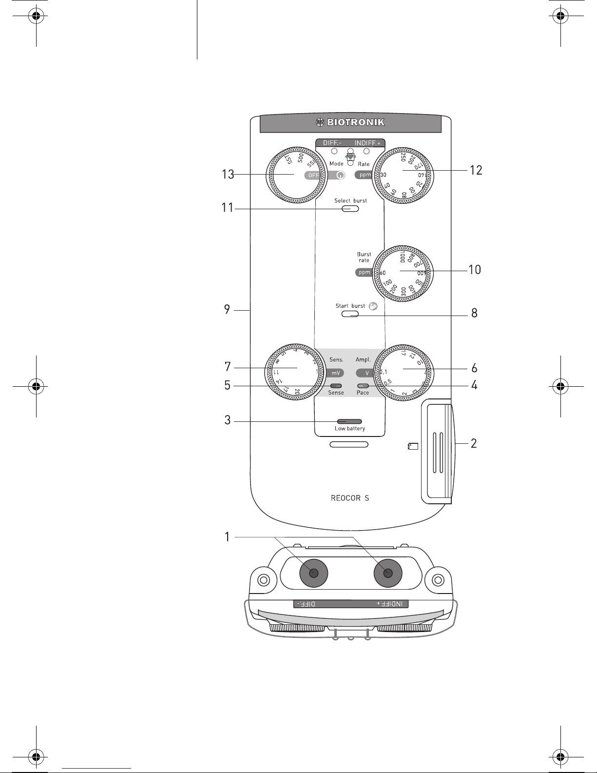
Figure 1: Reocor S operating panel
Page 14

Table 1: Description of elements in Figure 1
Designation Function
1 Patient connection
INDIFF.+; DIFF.-
For cables with 2-mm plug or for Redel adapters
(red = plus; blue = minus)
2 Battery compartment For 9-V block battery
3 Low battery LED Provides a warning when the battery voltage is too low
4 LED Pace Yellow display for stimulated event
5 LED Sense Green display for sensed event
6 Ampl. control dial Setting the pulse amplitude
7 Sens. control dial Setting the sensitivity
8 Start burst Starting the burst function
9 Velcro harness Secures Reocor S to patient, bed or infusion stand
10 Burst rate control dial Setting the burst rate
11 Select burst Selection of the burst function
12 Rate control dial Setting the pacing rate
13 Mode dial Selection of the pacing mode and off switch
11
Français English
Česky
EspañolItalianoNederlands
Polski
Português Magyar
Deutsch
Bold labels of the operating devices indicate safe values for
the intended use of the device.
Protective Cover
The protective cover is locked when the cover has been
pushed to the stop, passing two snap-in points and when the
lever is resting on the rail (see Figure 2).
Correct: False:
Figure 2: Correct positioning of the protective cover
Page 15

12
To release the protective cover (see Figure 3):
Push the release lever up with one hand.
At the same time, use your other hand to slide down the
protective cover.
Figure 3: Unlocking the protective cover
To lock the protective cover:
Slide the protective cover upwards along the rail until it
locks into place (see Figure 2).
The protective cover can be removed completely for cleaning.
Push the cover all the way down to the stop and then remove
it.
Caution! During use of Reocor S, the protective cover must be locked
to prevent inadvertent resetting of the rotary switch and con
-
trol dial, and thus of the programmed parameters.
Lead Connection
Reocor S has two connector ports for direct connection of
leads with touch-proof 2-mm plugs.
To connect cables with Redel plugs, the Redel adapter must
be fitted on the correct side and screwed in (Figure
4). The
Redel adapter is attached to the correct side if it can be
screwed on to the Reocor
S.
Note: The function of the Redel adapter is only guaranteed if it is
attached to the correct side!
Page 16

13
Français English
Česky
EspañolItalianoNederlands
Polski
Português Magyar
Deutsch
Figure 4: Redel adapter for Reocor S
Reocor S can be used with the following patient cables and
ad
apters:
• P
atient cable PK-83-B with two screw terminals for tem-
porary leads on the patient side
and Redel plug on the
Reocor S side (use the Redel adapter).
Figure 5: Patient cable PK-83-B
• P
atient cable PK-83 with two insulated screw terminals
for temporary leads on the patient side and two touchproof 2-mm plugs on the Reocor S side.
Figure 6: Patient cable PK-83
Page 17

14
• Patient cable PK-82 with two insulated alligator clips for
temporary leads on the patient side and two touch-proof
2-mm plugs on the Reocor S side.
Figure 7: Patient cable PK-82
• Patient cable PK-67-L and PK-67-S
Patient cable PK-67-L (2.6 m) and PK-67-S (0.8 m) differ only
i
n length. On the Reocor S side you have a Redel plug (use the
Redel adapter) and on the patient side a connection for the
adapter according to Figure 13 and for the single-use cable
according to Figure 9.
Figure 8: Patient cable PK-67-L and PK-67-S
• Cab
le for single use
The single-use cables Remington 301-CG (USA only) and
PK-155 with alligator clips are connected to the patient via
th
e cable PK-67-S.
Figure 9: Single-use cables PK-155 and 301-CG (USA only)
Only for USA: The single-use cables S-101-97 and FL-601-97
by R
emington Medical Inc. are connected via the reusable
adapter cable ADAP-2R to the Reocor S (Figure 10).
Figure 10: USA only: Remington single-use cable and adapter
Page 18

15
Français English
Česky
EspañolItalianoNederlands
Polski
Português Magyar
Deutsch
Reocor S can also be used with patient cables with 4 connections for dual-chamber pacemakers. Reocor S only uses the
v
entricular channel of these cables.
The following cables are possible:
• P
atient cable PK-141 with 4 alligator clips on the patient
side and Redel plug on the Reocor S side (use the Redel
adapter).
The ventricular channel is indicated by the label Vent
Diff/Indiff on the protective sleeves.
Figure 11: Patient cable PK-141
• P
atient cable PK-175 with four screw terminals on the
patient side and Redel plug on the Reocor S side (use the
Redel adapter
). The ventricular channel is labeled with
Ventricle.
Figure 12: Patient cable PK-175
Page 19

16
•Adapter
Figure 13 shows adapters for connection of temporary leads
to Reocor S through the dual-chamber patient cable PK-67L/S. T
he leads should be connected with the ventricular con-
nection of the adapter (labeled V).
Figure 13: Adapters for the patient cables PK-67-L and PK-67-S
PA-1-B and PA
-1-C for the connection of touch-proof 2-mm
plugs or MHW adapters (adapters for heart wires)
PA-2 IS
-1
PA-4 wi
th alligator clips
Connection
WARNING! Danger to patient by damaged cables.
Damaged cables are limited in functionality and pose a
da
nger to patients. Do not use damaged cables.
WARNING! Danger
from loss of function.
Damp cables have limited functionality and pose a danger to
pat
ients. Do not use damp cables.
WARNING! Dan
ger from electrical currents.
Unused cable contacts can condu
ct electrical currents to
patients. Adhere unused cable contacts close to the patient.
Caution! All
ergic reactions and inflammations.
Prevent the cable from coming into contact with the patient's
wo
unds or skin.
Note: En
sure correct fitting of the insulators prior to using the
cables.
Page 20

17
Français English
Česky
EspañolItalianoNederlands
Polski
Português Magyar
Deutsch
Note: For use of cables or adapters for dual-chamber applications,
the leads must be connected to the ventricular channel
(labeled Ventricle or V).
Note: Do n
ot connect the patient cable to the temporary pacing lead
of the patient before the connection has been established to
the Reocor S.
Direct connection
If Reocor S is used without the Redel adapter, temporary
cath
eters and heart wires can be connected to the patient
cables PK-82 and PK-83 directly at the connector ports
INDIFF.+ and DIFF.-.
Patient cable
The patient cable is connected via a Redel adapter to the
Reoc
or S.
Fit the Redel adapter to Reocor S.
Scr
ew the adapter in tight.
Insert the Redel plug of the patient cable into the Redel
port of the adapter.
Connection Variants
Temporary catheters with 2-mm plugs or heart wire with
2-mm adapter
You have the option to connect Reocor S directly to a temporary catheter with touch-proof 2-mm plug or to a heart wire
wi
th 2-mm adapter, without any other cables or adapters. All
other connection options are listed in the following table:
Patient-side
connection
BIOTRONIK cable Device-side
connection
Reocor S connection
Recommended connections
Direct connection (without BIOTRONIK cables) 2-mm connector port
2 mm PK-67-S/L with PA-1-C
Redel plug Redel adapter
Screw terminals PK-83B with TC Adapt
Redel plug 2-mm connector port
Screw terminals PK-83 with TC Adapt
2-mm plug 2-mm connector port
Possible connections
2 mm PK-67-S/L with PA-1-B
Redel plug Redel adapter
Alligator clips PK-141
Redel plug Redel adapter
Alligator clips PK-67-S/L with PA-4
Redel plug Redel adapter
Alligator clips PK-67-S/L with PK-155
Redel plug Redel adapter
Alligator clips PK-82
2-mm plug 2-mm connector port
Page 21

18
Heart wire with break-off needle or with flexible end
(max. 2.3 mm in diameter)
Implanted lead with IS-1 connector
Note: For dual-chamber cables (PK-141, PK-175, PK-67-S/L),
Reocor
S uses only the ventricular channel!
Polarity
Reocor S principally paces in bipolar mode, but it can be used
with bipolar or unipolar temporary pacing leads.
If unipolar leads are used, two leads must be connected.
Separating connections
Disconnect patient cables from the temporary pacing leads of
the patient or disengage the direct connection.
Separating Redel plug
• Retract the retaining ring at the Redel plug and pull the
Redel plug off the Redel port.
Patient-side
connection
BIOTRONIK cable Device-side
connection
Reocor S connection
Recommended connections
Screw terminals PK-83B Redel plug
Redel adapter
Screw terminals PK-83 2-mm plug
2-mm connector port
Possible connections
Screw terminals PK-175 Redel plug
Redel adapter
Alligator clips PK-141 Redel plug
Redel adapter
Alligator clips PK-67-S/L with PA-4 Redel plug
Redel adapter
Alligator clips PK-67-S/L with PK-155 Redel plug
Redel adapter
Alligator clips PK-82 2-mm plug
2-mm connector port
Connection
patient-side
BIOTRONIK cable Connection
device-side
Reocor S
connection
Recommended connections
IS-1 connector
port
PK-67-S/L with PA-2 Redel plug
Redel adapter
Possible connections
Alligator clips PK-141 Redel plug
Redel adapter
Alligator clips PK-67-S/L with PA-4 Redel plug
Redel adapter
Alligator clips PK-67-S/L with PK-155 Redel plug
Redel adapter
Alligator clips PK-82 2-mm plug
2-mm connector port
Page 22

19
Français English
Česky
EspañolItalianoNederlands
Polski
Português Magyar
Deutsch
Start Up
The operation of Reocor S is identical for all operating
modes. The operating steps should be carried out in the fol
lowing order (the numbers in parentheses refer to Figure 1 on
page 10).
• Insert battery.
• Push protective cover down.
• Prepare patient: Place the leads but do not connect them
to the pacemaker yet.
• Prepare Reocor S:
• Set the pacing rate with the Rate control dial (12).
• Set the pacing amplitude with the Ampl. control dial (6).
• Select the pacing mode with the dial Mode (13). The
device will be activated at the same time.
• After the internal self-test has been completed success-
fully, the LEDs on the operating panel simultaneously
flash twice.
• If the Low battery LED (3) flashes, the battery needs to be
replaced (for battery exchange, see page
20).
• Connect leads; the yellow Pace LED (4) flashes in syn-
chrony with the pacing pulses.
• Set the sensitivity with the Sens. control dial (7) so that
the green Sense LED (5) flashes in synchrony with every
sensed event.
• A sufficient safety margin should be considered to ensure
reliable sensing.
• Monitor the ECG of the patient and adjust amplitude
and/or sensitivity, if necessary.
Caution! During use of Reocor S, the heart rate of the patient must be
monitored with an ECG monitor with alarm function.
Attachment
Reocor S must be operated either horizontally on a non-slip
surface or affixed to the patient with an armband, or from a
hanging position on the infusion stand using the hanger on
the back of the device.
To attach Reocor S to an infusion stand, unscrew the hanger
from the back of the device. This ensures safe operation and
unburdens the patient cables.
Page 23

20
Battery Exchange
When the Low battery LED (3) starts flashing, it indicates that
the battery is almost depleted. When using the battery type
MN 1604 Duracell
®
Procell® approximately 36 hours of service time remain. However, the battery should be replaced as
soon as possible.
Reocor S must be operated with a 9-V battery, international
code IEC
6LR61. Only leakproof alkaline manganese batteries should be used. When using the battery type MN 1604
Duracell
®
Procell®, external pacing is possible for at least
600 hours at 20
± 2°C before the battery must be replaced.
It is possible to exchange a battery while Reocor S is in use.
The device remains ready for use for at least 30
s at the ambi-
ent temperature (20 ± 2°C) when the battery is removed.
For safety reasons, the patient should be paced by another
source during the battery replacement.
Do not use rechargeable batteries. The service time of these
batteries is difficult to estimate, making it possible to inad
-
vertently exceed the ERI, resulting in a sudden loss of pacing.
The battery compartment (2) is located on the right side of the
device, and can be opened by pushing the blue slider upwards
and pulling out the drawer towards the right. Remove the bat
-
tery carefully.
To protect the battery poles, a rubber plug can be put on the
new battery. Remove it before you insert the new battery.
Caution! The preferred pole orientation is marked in the battery com-
partment. When inserting the new battery you only need to
ensure that the battery poles point to the middle of the hous
ing. The position of the plus and minus pole can be selected
freely.
Page 24

21
Français English
Česky
EspañolItalianoNederlands
Polski
Português Magyar
Deutsch
Insert the new battery with the bottom (Figure 14) down first
into the battery compartment.
Figure 14: Inserting the battery
Close the drawer and press the blue slider down until it snaps
i
n place with an audible click.
Note: I
f the pacemaker is stored or will not be used for a long period
of time, it is recommended to remove the battery to prevent
damage due to leakage.
Page 25

22
Pacing Modes and Parameters
Pacing Modes
There are three pacing modes available: S00, SSI, SST as well
as high-frequency pacing (Burst).
For disturbances caused by electromagnetic interference
(EMI), after certain limits are exceeded Reocor
S will switch
to operating mode S00 for the duration of the disturbance.
Mode S00 The pacemaker sends pulses with a constant rate. The pulses
are asynchronous, i.e. not synchronized with the intrinsic
heartbeats. This mode functions when connected to the
ventricle as V00 and to the atrium as A00.
Mode SSI The pacemaker inhibits pulses when intracardiac potentials
are sensed. It sends pulses if no event is sensed within one of
the intervals corresponding to the selected frequency.
This mode functions when connected to the ventricle as VVI
and when connected to the atrium as
AAI.
Mode SST The triggered pacing mode SST corresponds to the pacing
modes SSI with the following distinction: no pulse inhibition
takes place upon sensing of an event outside of the refractory
period, instead pulse delivery is carried out immediately in
the respective chamber.
High-frequency
pacing
The rate of the burst function can be selected with the control
dial (10) from 60
ppm to 1000 ppm. This function is activated
with two key buttons: First the Select burst key button (11)
must be pressed and then, within two seconds, the
Start
burst key button (8) must be pressed. The pulse delivery
then lasts as long as the Start burst key button is pressed.
WARNING! After a burst stimulation in the atrium, the ventricular blank-
ing interval can prevent sensing of intrinsic signals and lead
to asynchronous pacing in the ventricle.
Rate
The rate can be continuously adjusted from 30 ppm to
250
ppm with the Rate control dial (12). If a value greater than
180
ppm is set, the device will sound a warning signal for
two
seconds.
WARNING! Pacing the heart with rates higher than 180 ppm over a long
time period can cause severe hemodynamic complications.
Pacing with high rates should only be performed when con
-
tinuous monitoring is ensured.
Page 26

23
Français English
Česky
EspañolItalianoNederlands
Polski
Português Magyar
Deutsch
Pulse Amplitude and Pulse Width
The pulse amplitude can be set with the Ampl. control dial (6)
within a range from 0.1
V to 17 V. If a value less than 1 V is set,
the device will sound a warning signal for two
seconds.
The pulse width is 1 ms.
Pacing should be checked regularly to ensure that pacing is
effective and that a sufficient safety margin has been set.
Sensitivity
The sensitivity can be adjusted with the Sens. control dial (7)
between 1
mV and 20 mV. It should be checked regularly to
ensure that correct sensing takes place and that a sufficient
safety margin has been set.
Interference interval
The interference interval is started both by paced and sensed
events.
The interval is reset if noise is sensed during the interval
length of 80
ms, leading to asynchronous pacing at the pro-
grammed rate for as long as the interference lasts.
Burst
The rate of the atrial Burst rate function can be selected with
the control dial (10) between 60
ppm and 1000 ppm.
This function is activated with two key buttons: First the
Select burst key button (11) must be pressed and then, within
two seconds, the Start
burst key button (8). The pulse delivery
then lasts as long as the Start burst key button is pressed.
Pacing the heart with rates higher than 180 ppm over a long
time period can cause severe hemodynamic complications.
Pacing at high rates should only be performed when continu
-
ous monitoring is ensured.
The mode for high-frequency pacing is used to terminate cer-
tain supraventricular tachycardias (SVT) and should only be
considered for atrial applications. The application of asyn
chronous high-frequency stimuli can interrupt an SVT by
depolarizing portions of a reentry path. When an ectopic
atrial focus is responsible for an SVT, the application of highfrequency stimuli in the atrium can also lead to increased
suppression of the ectopic center.
Page 27

24
Various risks have to be considered in association with highfrequency atrial pacing. The risks possible ventricular pacing
and ventricular tachycardia or fibrillation. This can be caused
by poor placement of the leads or the presence of anomalous
stimulus conduction paths that circumvent the normal atrio
ventricular stimulus conduction (e.g. Wolff-Parkinson-White
Syndrome). Patient discomfort and asystole after highfrequency pacing are other possible problems.
Page 28

25
Français English
Česky
EspañolItalianoNederlands
Polski
Português Magyar
Deutsch
Handling, Care and Maintenance
Reocor S
Reocor S is a highly developed precision device that must be
treated with care. Mechanical impact, e.g. by dropping the
device, can impair its function.
Please return the device to BIOTRONIK in case of damage or
impaired function.
Prior to use, the pacemaker should be stored at least two
hours under the ambient conditions specified for operation
(see page
30).
Housing, operating devices, connections, and patient cables
must be visually inspected for mechanical damage, deforma
-
tion, loose parts, cracks, and dirt before each use.
WARNING! Never use a damaged device or a device that exhibits abnor-
mal behavior; especially if it has been dropped or could have
been damaged by high-frequency or defibrillation voltage.
Secure Reocor S either horizontally on a non-slip surface or
on the patient with an armband, or operate it from a hanging
position on the infusion stand using the hanger on the back of
the device.
Caution! Reocor S must not be worn directly on the skin.
Cleaning A moist cloth and, if necessary, mild soap can be used to
clean Reocor
S. Strong cleaning agents or organic solvents
(such as ether or gasoline) should be avoided, as these can
corrode the plastic housing.
Disinfection For disinfection, wipe the device with a cloth soaked with a
disinfectant solution (e.g. Aerodesin 2000 or Lysoform D).
When mixing the solution, follow the dilution measure stated
by the manufacturer.
Note: After cleaning or disinfection, Reocor S must not be used for
one hour.
Sterilization Reocor S cannot be sterilized. If the device needs to be used
in a sterile environment, it can be packed into a sterile cover.
Annual checks of the device by manufacturer-authorized
technicians are recommended.
Caution! Even though Reocor S is protected from dripping water, the
device should be kept clean and dry.
Page 29

26
Reusable Patient Cables
Prior to opening, the package of a sterile cable must be
inspected for damage to determine whether sterility has
been compromised.
Cleaning The reusable patient cables can be cleaned and disinfected
with hospital cleaning agents following many different
methods. However, aggressive chemicals (such as acetone)
may never be used.
The use of a wiping cloth with regular, alcohol-free hand soap
or the cleaning agent Stabimed by Braun is the recom
mended cleaning method for the cables. Subsequently, the
cables must be cleaned from cleaning agent residue with
electrolyte-free water and then wiped with a clean, dry cloth.
Disinfection For disinfection in a disinfectant bath, an aldehyde-based
(e.g. Lysoformin 3000) or alcohol-based (e.g.
Aerodesin 2000)
disinfectant agent must be used in accordance with the man
ufacturer information and in accordance to the respective
hospital guidelines.
After disinfection, the cable must be cleaned from residues of
the disinfectant by rinsing it in electrolyte-free water.
Sterilization All patient cables can be sterilized as follows unless other-
wise stated in the patient cables' documents:
• Steam sterilization at 121 °C and 1.1 bar for 20 min.
PK-175 and PK-83-B patient cables can also be sterilized as
follows:
• Steam sterilization at 134 °C and 3.0 bar for 18 min.
Maintenance, Service, Inspections
The only required maintenance action is the replacement of
the battery (see page
20).
No other maintenance work is required.
Test before use A short test should be performed prior to each use of the
device. It consists of a visual inspection and a simple function
test.
Visual inspection:
• Inspect the housing for mechanical damage, deforma-
tion, loose parts, cracks, etc.
• Inspect the cable connection area for mechanical
damage.
• Inspect the labeling for legibility.
Page 30

27
Français English
Česky
EspañolItalianoNederlands
Polski
Português Magyar
Deutsch
Function test:
The result of the self-test that runs automatically after
activation must be heeded.
Inspection Inspections should be performed:
• after an application together w
ith high-frequency surgi-
cal instruments or defibrillator
s,
• when malfunctions are suspected,
•once a year.
The inspection should follow the manufacturer specifica-
tions. These are made available upon request. The specification lists all required test steps and the necessary equipment.
Disposal
Reocor S is marked with the symbol of a crossed-out garbage
can on its type plate. The symbol indicates that the European
guideline 2002/96/EC on waste electrical and electronic
equipment (WEEE directive) applies to the disposal method of
the device.
Old devices and accessories that are no longer needed,
such as patient cables and adapter
s, should be returned to
BIOTRONIK. This ensures that proper disposal will be carried
out in accordance with the national implementations of the
WEEE directive.
Note: Ca
bles to be disposed of due to contact with blood must be
disposed of as medical waste, in accordance with environmental regulations. Non-contaminated cables must be disposed of in accordance with t
he European Directive 2002/96/
EC regarding waste electrical and electronic equipment
(WEEE).
Depleted batteries must be treated as hazardous waste and
di
sposed of by the user.
If you have any questions, please contact BIOTRONIK.
Page 31

28
Technical Safety
The external pacemaker Reocor S meets the international
standards for the safety of electro-medical devices according
to IEC
60601-1 and IEC 60601-1-2, as well as the international standard IEC 60601-2-31 for temporary, external pacemakers.
The following special features offer safety for the patient:
• No metal parts that can be touched, according to the
definition of the IEC.
• The design meets the standard for the device class CF
(cardiac floating) and is approved for direct treatment of
the heart. The pacemaker complies with the require
ments for defibrillation protection stipulated in the international standards.
• The closed protective cover protects the pacemaker
against dripping water.
WARNING! The temporary leads that are connected to Reocor S repre-
sent a low-impedance conductor to the myocardium for electric current. Therefore line-powered devices that are operated in the patient's vicinity must be grounded in accordance
with established guidelines.
The pacemaker must not be used in areas at risk for explosion.
All additional maintenance work and repairs should only be
performed by BIOTRONIK.
Page 32

Adjustable parameters
Pacing modes S00, SSI, SST
Basic rate (30 … 250 ppm) ± 1 ppm At a rate of > 180 ppm a warning
t
one is emitted
Pulse amplitude 0.1 … 17 V ± max. (50 mV, 10%) At a pulse amplitude of < 1 V a
war
ning tone is emitted
Sensitivity 1 … 20 mV ± 15% With respect to 40 ms sin
2
pulse
Burst rate (A) (60 … 1000 ppm) ± 20 ppm
29
Français English
Česky
EspañolItalianoNederlands
Polski
Português Magyar
Deutsch
Technical Data
Symbols
Follow the instructions for use in the technical manual.
Indication of the placement of the battery in the compartment
Disposal according to the WEEE directive
Applied part classification: CF (cardiac floating), defibrillation protected
IP31 Water-repellent, protection degree IP31
OFF Off (on the Mode dial)
Fixed parameters
Pulse width 1 ms ± 5%
Auto short after pace < 20 ms ± 10%
Interference interval 80 ms ± 5 ms
In channel blanking 110 ms ± 3 ms
Refractory period
(30 … 150) ppm
(151 … 200) ppm
(201 … 250) ppm
225 ms ± 5 ms
200 ms ± 5 ms
175 ms ± 5 ms
Upper rate 260 ppm ± 10%
Page 33

30
High rate protection
1 … 180 ppm
181 … 250 ppm
286 ms ± 10%
214 ms ± 10%
286 ms = 210 ppm, does not apply
f
or Burst
214 ms = 280 ppm, does not apply
f
or Burst
Pulse waveform Asymmetric, biphasic
Lead impedance monitoring
Acoustic warning Above 2000 Ω ± 15%, at 5 V amplitude
Lead connection Touch-proof 2-mm connector ports;
Redel port, 6-pin via Redel adapter
Electrical data/battery
Battery
Polarity Cathodic
Inverse-polarity protection None: Polarity is irrelevant
Power consumption Typically 1 mA (70 ppm, 5.0 V, 500 Ω )
Service time with new bat-
tery
b)
b) When using the battery type MN 1604 Duracell®, Procell
®
End of service (EOS) Flashing “Low battery” LED
Remaining service time
af
ter ERI signal
b)
Behavior during battery
exchange
Ambient conditions
Temperature range for operation +10°C … +40°C
Temperature range for storage 0°C … +50°C
Relative humidity 30% … 75%, non-condensing
Atmospheric pressure 700 hPa … 1060 hPa
Noise level 50 dB
Fixed parameters
• Alkaline-manganese type: IEC 6LR61 / ANSI 1604A
• 9 V leak-proof
• E.g. MN1604 Duracell
®
Procell
®a)
• 600 h (-10%) at 20°C (± 2°C)
• At: 70 ppm, 5 V, mode VVI, 500 ohm
• Until: ERI signal (EOS warning)
• 36 hours
•
At: 70 ppm, 5 V, mode VVI, 500 ohm
• Device remains ready for use for at least 30 s when the battery
is
removed.
• The set Mode is retained.
a) Registered trademark of Duracell Inc., Bethel, CT 06801
Page 34

Dimensions, weight, material
Reocor S dimensions 160 mm x 75 mm x 35 mm ±2 mm (without Redel adapter)
Reocor S weight With battery, with Redel adapter: 305 g ± 10%
Without battery, with Redel adapter: 260 g ± 10%
Without battery, without Redel adapter: 225 g ± 10%
Dimensions of the Redel
ad
apter for Reocor S
76 mm x 35.5 mm x 29.4 mm
Weight of Redel adapter for
Re
ocor S
35 g ± 10%
Housing material Babyblend FR 3000 (PC-ABS)
Classification
Applied part classification CF (cardiac floating), defibrillation protected
Safety class II b
Protection degree IP31 (water-repellent)
Defibrillation-proof level 5 kV
Operating mode Continuous operation
Estimated service life
a)
a) The service life describes the expected maximum operating life time of the device after distri-
bution. The expected maximum operating life tim
e is not supported by any test data.
(according to
EN 60601-1:2007, 4.4)
12 years
31
Français English
Česky
EspañolItalianoNederlands
Polski
Português Magyar
Deutsch
Page 35

32
Conformity According to IEC 60601-1-2
Manufacturer guidelines and declaration electromagnetic radiation (IEC 60601-1-2: Table 1)
The device is intended for use in an electromagnetic environment as described below. The use
r sho uld make sure that the
device is used in such an environment.
Emissions test Compliance level Guidelines for the electromagnetic environment
HF emission
according to CISPR 11
Group 1 The device uses HF energy exclusively for its own
f
unction. Therefore, the high-frequency interference is very low and not likely to cause any
int
erference in nearby electronic equipment.
HF emission
according to CISPR 11
Class B The device is suitable for use in all areas, exclud-
ing residential areas and buildings that are connected directly to the public power supply.
Emission of harmonic
osc
illations according to
IEC 61000-3-2
Not applicable
Voltage fluctuations
a
ccording to
IEC 61000-3-3
Not applicable
Manufacturer guidelines and declaration –
resistance to electromagnetic interference
(IEC 60601-1-2: Table 2)
The device is intended for use in an electromagnetic environment as described below. The user of the device should make
sur
e that it is used in such an environment.
Test of resistance
to interference
Test le vel ac co rdi ng to
IEC
60601
Compliance
level
Guidelines for the electromagnetic environment
Electrostatic
dis
charge (ESD)
according to
IEC 61000-4-2
±6 kV contact
di
scharge
±8 kV air discharge
±6 kV contact
discharge
±15 kV air
di
scharge
Floors should be made of wood,
c
ement or ceramic tiles. When the
floor consists of a synthetic material, the relative humidity must be at
le
ast 30%.
Fast transient
el
ectric interference/bursts
a
ccording to
IEC 61000-4-4
Not applicable
Surges voltages
(surges) according to IEC 610004-
5
Not applicable
Page 36

33
Français English
Česky
EspañolItalianoNederlands
Polski
Português Magyar
Deutsch
Manufacturer guidelines and declaration – resistance to
electromagnetic interference for all external pacemaker
models (IEC 60601-1-2: Table 3)
The device is intended for use in an electromagnetic environment as described below. The user of the device should make
sur
e that it is used in such an environment.
Voltage drops,
brief interruptions and fluctuations in the supply
v
oltage according
to IEC 61000-4-11
Not applicable
Magnetic field at
the suppl
y
frequencies (50/
60 Hz) according
to
IEC 61000-4-8
3 A/m 30 A/m The magnetic field strength should
c
orrespond to the typical value in
business and hospital environments.
Test of resistance
to interference
Test le vel ac co rdi ng to
IEC 60601
Compliance
level
Guidelines for the electromagnetic environment
Test of resistance
to interference
Test le vel ac co rdi ng to
IEC
60601
Compliance
level
Guidelines for the electromagnetic
environment
Portable and mobile radio devices
ar
e not used closer to any part of
the device, including cables, than
the recommended safe distance.
Recommended safe distance:
Conducted HF
i
nterferences
according to
IEC 61000-4-6
10 V
rms
10 kHz to 80 MHz
outside of the ISM
bands
a
10 V
rms
d = 0.35 P
10 V
rms
10 kHz to 80 MHz
inside of the ISM
bands
a)
10 V
rms
d = 1.2 P
Radiated HF interference according
to
IEC 61000-4-3
10 V/m
800 MHz to 2.5 GHz
10 V/m
d = 1.2 P
for 80 MHz to 800 MHz
d = 2.3 P
for 800 MHz to 2.5 GHz
Page 37

34
P is the maximum rated power of
the transmitter in watts [W] according to the information from the
tr
ansmitter manufacturer and d is
the recommended safe distance in
meters [m]
b)
.
The field strength of stationary
tr
ansmitting devices must be measured on site
c)
and must be lower
than the compliance level at all
fr
equencies
d)
.
Interference can occur in devices
t
hat have the following warning
sign.
COMMENT: These guidelines do not necessarily apply in all situations. The spread of electromagnetic waves is influenced by absorption and refl
ection from buildings, objects, and humans.
a) The ISM bands (for industrial, scientific and medical applications) between 150 kHz and
80 MHz are 6.765 MHz to 6.795 MHz; 13.553 MHz to 13.567 MHz; 26.957 MHz to 27.283 MHz
and 40.66 MHz to 40.70 MHz.
b) The compliance level in the ISM frequency bands between 150 kHz and 80 MHz and in the fre-
quency range 80 MHz to 2.5 GHz is designed to reduce the likelihood that mobile communication devices cause interference if they are unintentionally brought into the patient area. For
t
his reason a greater safety distance is recommended in these frequency ranges (factor 1.2
instead of 0.35).
c) The field strengths of stationary transmitters, suc
h as base stations for cellular phones and
land mobile radios, amateur radio stations and radio and TV broadcasts cannot be predicted
with accuracy. To assess the electromagnetic environment by fixed HF transmitters, a study of
the location should be considered. If the measured field strength exceeds the HF compliance
l
evel at the location where the device is used, the device must be observed to ensure correct
functioning. Additional measures may be necessary, such as re-orienting or relocating the
external pacemaker.
d) In the frequency range of 150 kHz to 80 MHz the field strengths should be less than 10 V/m.
Test of resistance
to interference
Test le vel ac co rdi ng to
IEC 60601
Compliance
level
Guidelines for the electromagnetic
environment
Page 38

35
Français English
Česky
EspañolItalianoNederlands
Polski
Português Magyar
Deutsch
Recommended safe distances to portable and mobile RF
communications equipment (IEC 60601-1-2: Table 5)
The device is intended for use in an electromagnetic environment, in which the RF interference is controllable. The user of
th
e device can help to prevent electromagnetic interference
by maintaining the safe distance to mobile RF communication
equipment (transmitters) - depending on the power output of
the communication equipment.
Rated power of
the transmitter
P [W]
Safe distance d [m] corresponding to transmission frequency
150 kHz to
80
MHz outside
the ISM bands
150 kHz to
80
MHz inside the
ISM bands
80 MHz to
800
MHz
800 MHz to
2.5 GHz
d = 0.35 P
d = 1.2 P
d = 1.2 P
d = 2.3 P
0.01 0.04 0.12 0.12 0.23
0.10 0.11 0.38 0.38 0.73
1.00 0.35 1.20 1.20 2.30
10.00 1.11 3.79 3.79 7.27
100.00 3.50 12.00 12.00 23.00
For transmitters whose rated power is not specified
in the table above, the safe distance can be
calculated using the specified formula for the corresponding frequency. Here P is the rated power
of the transmitter in watts [W] and d is the safe distance in meters [m].
COMMENT 1: The ISM bands (for industrial, scientific and medical applications) between 150 kHz
and 80 MHz are 6.765 MHz to 6.795 MHz; 13.553 MHz to 13.567 MHz; 26.957 MHz to 27.283 MHz
and 40.66 MHz to 40.70 MHz.
COMMENT 2: The compliance level in the ISM frequency bands between 150 kHz and 80 MHz and
in the fr
equency range 80 MHz to 2.5 GHz is designed to reduce the likelihood that mobile com-
munication devices cause interference if they are unintentionall
y brought into the patient area.
For this reason a greater safety distance is recommended in these frequency ranges (factor 1.2
instead of 0.35).
COMMENT 3: These guidelines do not necessarily apply in all situations. The spread of electromagnetic waves is influenced by absorption and reflection from buildings, objects, and humans.
Page 39

396
Apenas para os EUA
Artigo Nº para
pedido
Descrição
PA-1-B 123751
PA-1-C 349723
PA-2 123157
PA-4 123090
PK-155
(conj. de dois cabos)
337358 Cabo do paciente esterilizado, dois fios, com clipes jacaré
par
a uso único
Adaptador para PK-67 e PK-67-L
Adaptador para PK-67-S e PK-67-L
(apenas para EUA)
Artigo Fabricante Descrição
Modelo 301-CG Remington
Medical
Inc.
Cabo do paciente esterilizado, dois fios, com clipes jacaré
para uso único
Artigo Fabricante Descrição
Modelo 301-CG Remington
Medical
Inc.
Cabo do paciente esterilizado, dois fios, com clipes jacaré
para uso único
Modelo S-101-97
(2,5 m)
Remington
Medical
Inc.
Cabo do paciente, dois fios, com clipes jacaré para uso
único
Modelo FL-601-97
(2,0 m)
Remington
Medical
Inc.
Cabo do paciente, dois fios, com terminais rosqueáveis
para uso único
Adaptador para ADAP-2R (apenas para EUA)
PK-141 (2,8 m) 353181 Cabo do paciente, reesterilizável, com quatro
clipes jacaré com proteção contra contato
Adaptador
Redel
Braçadeira Reocor
pa
drão
103704
Braçadeira padrão –
Braçadeira Reocor
curta
391843
Artigo Fabricante Descrição Conexão
ADAP-2R
(0,24 m)
Remington
Medical
Inc.
Adaptador
Redel
Braçadeira com circunferência reduzida.
Apropriada para braços mais finos.
–
Artigo Nº para
pedido
Descrição Conexão
Adaptador reutilizável para cabo modelo
S-101-97 e modelo FL-601-97
Para conexão ao adaptador de 2 mm ou adaptador MHW
(adaptador para fios cardíacos), reesterilizável
Para conexão ao adaptador de 2 mm ou adaptador MHW
(adaptador
para fios cardíacos), reesterilizável
Para conexão ao conector IS-1, reesterilizável
Com clipes jacaré, reesterilizável
Page 40

397
Français English
Česky
EspañolItalianoNederlands
Polski
Português Magyar
Deutsch
Legenda da etiqueta
Os símbolos na etiqueta têm o seguinte significado:
Símbolo Significado
Reocor S
Adaptador Redel
Número para pedido BIOTRONIK
Número de série do aparelho
Data de fabricação do aparelho
Variação de temperatura de armazenamento permitida
Variação de pressão atmosférica de armazenamento permitida
Variação de umidade do ar de armazenamento permitida
Paciente com eletrodo implantado
Conteúdo
Símbolo de descarte
Observar o manual técnico!
Atenção: Conforme a lei dos Estados Unidos, a venda deste produto
é restrita para ou autorizado por um médico.
Marca CE
Page 41

398
Page 42

Técnico Responsável:
Eng. Zolmo de Oliveira Jr. - CREA/SP nº: 060 1869029
Eng. Rogério Quiarim Zarza - CREA/SP nº: 060 1812032
Marcapasso Externo Reocor S - Reg. ANVISA nº: 80224390178
Fabricante / Distribuidor:
BIOTRONIK SE & Co. KG
Woermannkehre, 1
D-12359 Berlim Alemanha
Tel.: (+49 30) 689 05-600
Fax: (+49 30) 689 2804
salesbiotronik.com
www.biotronik.com
Fornecedor:
BIOTRONIK Comercial Médica Ltda.
Rua dos Inocentes, 506
04764-050 São Paulo, SP
Tel.: (+55 11) 5694 7755
Fax: (+55 11) 5694 7770
CNPJ: 50.595.271/0001-05
15-D-xx
Revision: J (2015-01-26)
©
BIOTRONIK SE & Co. KG
All rights reserved. Specifications are subject
to modification, revision and improvement.
BIOTRONIK SE & o K
Woermannkehre 1
12359 Berln ermany
Tel +49 (0) 30 68905-0
Fax +49 (0) 30 6852804
salesbotronkcom
wwwbotronkcom
0123 2009
 Loading...