

Page 1

Protego DF-1 S ProMRI
Tripolar ICD lead with active fixation
Technical Manual
414086
Revision: E (2015-05-28)
®
© BIOTRONIK SE & Co. KG
All rights reserved.
Specifications subject to modification, revision and improvement.
0123 2015
Index 414086Technical ManualProtego DF-1 S
BIOTRONIK SE & Co. KG
Woermannkehre 1
12359 Berlin · Germany
Tel +49 (0) 30 68905-0
Fax +49 (0) 30 6852804
sales@biotronik.com
www.biotronik.com
Page 2

2 Table of Contents
Table of Contents
Table of Contents
Description . . . . . . . . . . . . . . . . . . . . . . . . . . . . . . . . . . . . . . . . . . . . . . . . . . . 3
About this Technical Manual . . . . . . . . . . . . . . . . . . . . . . . . . . 3
Design and Properties of the Lead . . . . . . . . . . . . . . . . . . . . . 4
Intended Use, Indications and Contraindications . . . . . . . . . 5
Packaging, Sterility, Storage, and Disposal . . . . . . . . . . . . . . 6
Safety . . . . . . . . . . . . . . . . . . . . . . . . . . . . . . . . . . . . . . . . . . . . . . . . . . . . . . . . 7
Medical and Technical Complications . . . . . . . . . . . . . . . . . . 7
Risky Therapeutic and Diagnostic Procedures and
Environmental Influences . . . . . . . . . . . . . . . . . . . . . . . . . . . . 8
Electrical and Electromagnetic Safety . . . . . . . . . . . . . . . . . 10
Handling and Implantation . . . . . . . . . . . . . . . . . . . . . . . . . . . . . . . . . . . . . 11
Implantation: Basic Instructions and Safety Measures . . . 11
Information on the Steroid Collar . . . . . . . . . . . . . . . . . . . . . 12
Opening the Package . . . . . . . . . . . . . . . . . . . . . . . . . . . . . . . 13
Checking the Function of the Fixation Screw before
Implantation . . . . . . . . . . . . . . . . . . . . . . . . . . . . . . . . . . . . . . 14
Accessing the Vein and Inserting the Lead . . . . . . . . . . . . . 15
Positioning and Fixating the Lead. . . . . . . . . . . . . . . . . . . . . 16
Intraoperative Measurements and Tests . . . . . . . . . . . . . . . 18
Fixating the Lead at the Lead Incision Point . . . . . . . . . . . . 20
Connecting the Lead to the Active Device . . . . . . . . . . . . . . 21
Lead Placement . . . . . . . . . . . . . . . . . . . . . . . . . . . . . . . . . . . 23
Appendix . . . . . . . . . . . . . . . . . . . . . . . . . . . . . . . . . . . . . . . . . . . . . . . . . . . . 24
Technical Data . . . . . . . . . . . . . . . . . . . . . . . . . . . . . . . . . . . . 24
Disclaimer. . . . . . . . . . . . . . . . . . . . . . . . . . . . . . . . . . . . . . . . 27
Legend for the Label . . . . . . . . . . . . . . . . . . . . . . . . . . . . . . . 28
Page 3

3 Description
1 Description
Description1414086Technical ManualProtego DF-1 S
About this Technical Manual
Target group This technical manual is targeted at medical personnel and cardiologists who are
familiar with the following topics:
• The use of ICDs and the respective leads, tachycardia therapy
• The implantation methods required for this as well as the associated risks and
possible complications
This technical manual This technical manual is either included in hard copy form in the product packaging
or can be downloaded as a file from the Internet. In the latter case, the package will
include an insert with the URL instead of a hard copy of the technical manual.
Note: Keep this technical manual for later use.
Observe other manuals Please also observe the technical manuals and accompanying documents for
devices combined with this lead (ICD, pacemaker, additional leads) and for devices
and accessories used during implantation.
Page 4
4 Description
Design and Properties of the Lead
Product name Protego DF-1 S
Model Length
Protego DF-1 S 60 61 cm
Protego DF-1 S 65 65 cm
Protego DF-1 S 75 75 cm
Features at a glance
Lead body The lead body consists of coils and cables that form the electrical connection
Electrical properties The fixation screw is electrically active and forms the distal pole (tip electrode) of
• Fixation: Extendable/retractable fixation screw, electrically active
• Shock coil: 1 x RV
• Bipolar sensing and pacing in the ventricle
• Insulation surface coating improves the lead body's gliding properties
• Steroid collar on the lead tip reduces inflammatory processes and undesired
increases in threshold after implantation
• Connectors:
—1 x DF-1
—1 x IS-1 (bipolar)
between the contact pin on one hand and tip electrode, ring electrodes and shock
coils on the other. Coils and cables are embedded in silicone insulation, which
serves to insulate the conductors from each other and from the outside
environment. The external surface of the silicone insulation is coated to improve the
lead's gliding properties.
Details: Technical Data, p. 24 ff.
the lead.
Sensing and pacing occur between the distal pole and the ventricular ring
electrode.
The energy for cardioversion and defibrillation therapies is provided via the shock
coils.
Fixation The lead tip has an extendable/retractable screw for fixating the lead in the
myocardium.
Extend or retract the fixation screw by rotating the IS-1 connector pin and thereby
the conductor to the tip electrode. For improved handling, a fixation tool is provided
for the connector pin.
Steroid collar The lead tip has a steroid collar in the form of a rubber silicone ring that contains
dexamethasone acetate.
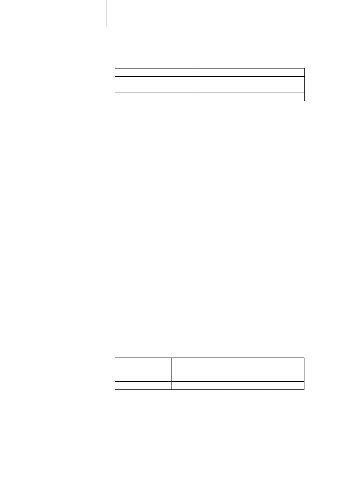
Lead connections The following applies for the connectors:
Connector for Lead connector Standards Label
Sensing, pacing IS-1 • ISO 5841-3
• EN 50077
Shock delivery DF-1 • ISO 11318 DF-1
IS-1 BI
Page 5

5 Description
Intended Use, Indications and Contraindications
Intended use and indications In combination with a compatible ICD, this lead is designed for the following:
• Permanent sensing and pacing in the right ventricle
• Delivery of defibrillation / cardioversion therapies
With its active fixation screw, this lead is especially suitable for patients with
degenerated trabeculae in the ventricle for whom passive fixation with silicone or
polyurethane tines is not possible.
Contraindications Implantation of this lead is contraindicated in the following cases:
• Patients with mechanical tricuspid valve prostheses or severe tricuspid valve
diseases
• Patients with a dexamethasone acetate intolerance
Guidelines For indications and contraindications of an ICD or pacemaker therapy, we also
recommend following the respective current guidelines of the Heart Rhythm
Society (HRS), the American College of Cardiology (ACC), the American Heart
Association (AHA), and the German Cardiac Society (Deutsche Gesellschaft für
Kardiologie, Herz- und Kreislaufforschung), as well as those of other national
cardiology associations.
Page 6
6 Description
!
!
!
!
!
!
Packaging, Sterility, Storage, and Disposal
Box and label The lead is delivered in a box bearing a quality control seal and a product
information label.
The label contains the following information about the lead:
• Name of model
• Technical properties and data
•Serial number
• Use by date
• Details on sterility
• Storage information
Sterility The lead and its accessories are packaged in a double blister and sterilized with
ethylene oxide. As a result, the inner blister is also sterile on the outside.
CAUTION
Risk to sterility due to damaged blister
To ensure sterility, the container should be checked for damage prior to opening.
Do not use a lead if you are unsure of its sterility.
CAUTION
Resterilization and reuse
This lead is intended for single use only. Reuse of leads can result in infections,
embolisms and damage to the device.
Resterilization and reuse are prohibited.
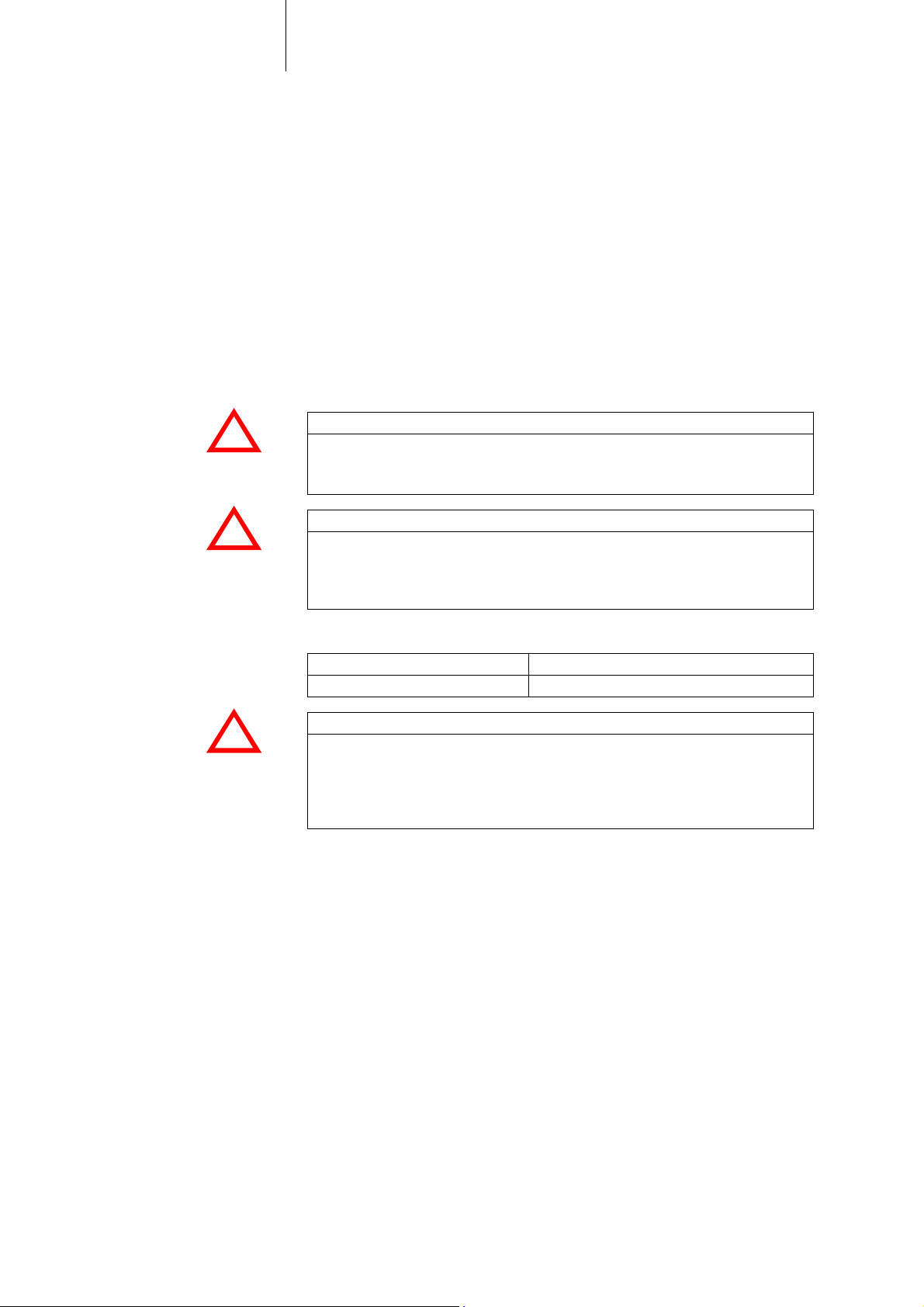
Storage Maintain the following storage conditions:
Storage temperature Maximum storage duration
5–50°C 2 years
CAUTION
Improper storage
If the specified time period and temperature range for storage are exceeded, then
the documented properties of the lead can no longer be guaranteed. Technical
malfunctions - as well as decreased effectiveness of the steroid in the case of
steroid-eluting leads - may result.
Disposal An explanted lead must be disposed of as medical waste in an environmentally
friendly and proper manner.
The lead does not contain any materials which require any further provisions.
Page 7
7 Safety
2 Safety
Safety2414086Technical ManualProtego DF-1 S
Medical and Technical Complications
Medical complications Potential medical complications of using implantable pacemakers or ICDs include
the following:
• Formation of fibrotic tissue
• Thrombosis, embolism
• Elevated pacing thresholds
• Foreign body rejection phenomena
• Lead erosion
• Pericardial tamponade
• Valvular damage
• Muscle and nerve stimulation
• Infection
• Pacemaker-induced arrhythmias (some forms of which can be life-threatening)
Technical complications The following could result in technical malfunctions of the device system, which
consists of pacemaker or ICD and leads:
• Incorrect lead implantation
• Lead dislodgement
• Lead fracture
• Insulation defect
• Battery depletion or component failure of the active device
Potential adverse events and
corrective measures
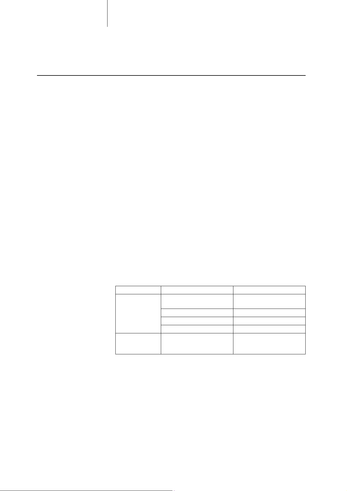
Some of the potential adverse events and corrective measures are listed in the table
below.
Problem Possible cause Corrective measure
Loss of pacing or
sensing
Significant
worsening of the
threshold
Improper connection between
lead and the active device
Lead dislodgement Reposition lead.
Lead fracture Replace lead.
Insulation defect Replace lead.
Excessive fibrotic tissue
formation
Properly connect the lead to
the active device.
Adjust pulse amplitude and
duration; reposition or replace
the lead.
Page 8

8 Safety
Risky Therapeutic and Diagnostic Procedures and Environmental Influences
Improper procedures The procedures listed in the following table must be avoided for patients with an
implanted lead or a device system (pacemaker or ICD).
Procedure Type of danger
Diathermy
Magnetic resonance imaging
(Please read the explanation at the
end of this section.)
Hyperbaric oxygen therapy • Penetration of bodily fluids into the lead or
Transcutaneous electrical nerve
stimulation (TENS), stimulation
current
• Tissue damage due to excessive heating of
the lead
• Induction of ventricular fibrillation
• Tissue damage due to excessive heating of
the lead
• Change of position of the lead (lead
dislodgement) or the active device
• Pulse inhibition, asynchronous and/or
triggered pulse delivery by the active
device
device
• Induction of ventricular fibrillation
Note: Tissue damage due to excessive heating usually causes change or loss of the
sensing and pacing function of the implanted lead.
Magnetic resonance imaging Magnetic resonance imaging is contraindicated due to the associated high
frequency fields and magnetic flux density.
• Patients with an implanted lead of this type may be examined using magnetic
resonance imaging only when specific measures have been taken to ensure the
safety of the patient and device.
• Please contact the responsible authorities or BIOTRONIK beforehand to
determine whether these products are actually certified "MR conditional" in
your country or region.
• You can find detailed information about the requirements, conditions and
measures for safely conducting an MRI scan in our manual "ProMRI
MR conditional device systems."
You can download this manual as a PDF file from
www.biotronik.com/manuals/manualselection or
https://manuals.biotronik.com or order a printed copy from BIOTRONIK.
®
,
Page 9
9 Safety
!
!
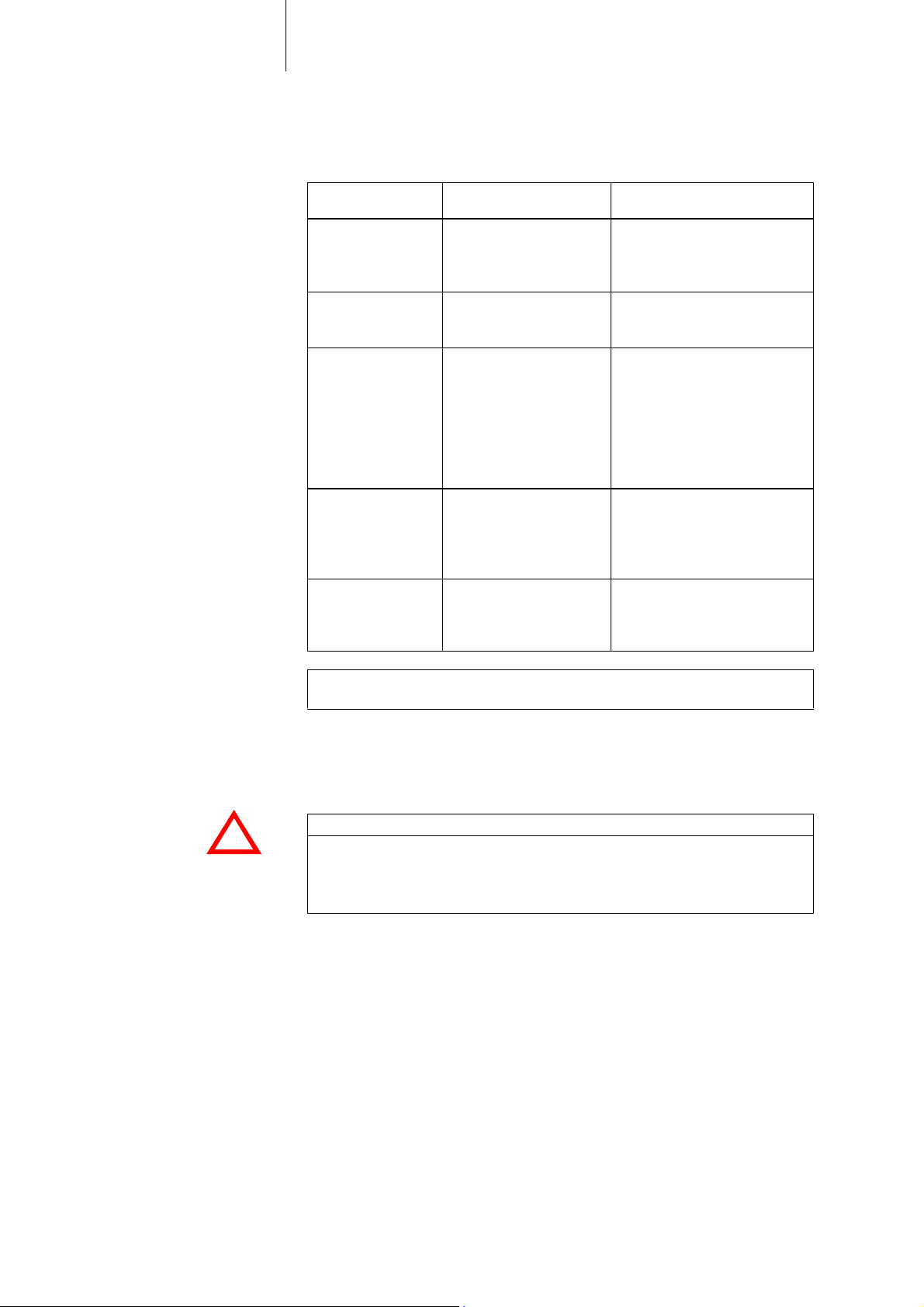
Risky procedures The table below provides an overview of procedures that present a risk to patients
with an implanted lead or a device system. Take appropriate precautionary
measures and observe the specific instructions listed in the table.
Procedure Type of danger Recommendations for risk
Therapeutic ultrasound
External defibrillation
Electrophysiological
ablation
HF surgery (electrocautery)
Lithotripsy Mechanical effect on or
Tissue damage due to
excessive heating of the
lead
Tissue damage due to
excessive heating of the
lead
Tissue damage due to
excessive heating of the
lead
Induction of ventricular
fibrillation
Damage to the lead
Tissue damage due to
excessive heating of the
lead,
Induction of ventricular
fibrillation
damage to the lead
mitigation
Do not direct the energy focus
onto the lead or the device.
Afterwards: perfom a full
follow-up.
Afterwards: perfom a full
follow-up.
Switch off the active device
beforehand.
Keep as much distance as
possible between the ablator
and the lead.
Following ablation and prior to
restarting the active device:
perfom a full follow-up.
Do not direct the energy focus
onto the lead or the device.
Afterwards: perfom a full
follow-up.
Keep energy focus from the
lead.
Afterwards: perfom a full
follow-up.
Problematic environmental
influences
Note: Tissue damage due to excessive heating usually causes change or loss of the
sensing and pacing function of the implanted lead.
• Increased ambient pressure:
The leads are manufactured under standard atmospheric pressure and are not
designed to withstand increased ambient pressure.
Stress resulting from excess pressure may damage the leads.
CAUTION
Damage and failure of the device system
Patients with device systems must avoid situations or environments in which they
would be exposed to high ambient pressures (such as diving or pressure chambers).
• Electromagnetic interference:
Electromagnetic fields may negatively affect patients with device systems as the
intensity and duration of exposure increase. This can have the following
consequences:
— Temporary or permanent effect on or damage to the device system
— Induction of tachycardias, up to and including ventricular fibrillation (in rare
cases)
— Thermal tissue damage (in severe cases)
The patient should be properly informed and instructed on behaviors to avoid
situations with especially risky electromagnetic effects.
Perform a follow-up for clarification if electromagnetic interference is
suspected to have impaired the function of the device system.
In most cases, the problem can be solved by reprogramming the device.
Page 10

10 Safety
!
!
Electrical and Electromagnetic Safety
Electrical safety Implanted leads are a direct electrical connection to the myocardium.
Therefore, it is important for the safety of the patient that no electrical energy other than the pulses from the active device - is conducted to the lead, neither by
direct contact nor indirectly due to electromagnetic conduction.
WARNING
Risk of death due to induction of ventricular fibrillation
Ensure that the contact surfaces of the lead connectors of implanted leads never
touch any electrically conducting or wet surfaces, including human hands or skin.
Electromagnetic induction A lead can receive electromagnetic energy as an antenna would and cause
electrical voltages at the lead tip and connector.
This can induce ventricular fibrillation in some cases, as well as damage or
otherwise affect the active device and, if the energy dose is high enough, even
damage the myocardium.
Note: For information about therapy or diagnostic procedures that pose a potential
risk, refer to the appropriate section of this manual (see Risky Therapeutic and
Diagnostic Procedures and Environmental Influences, p. 8).
Additional information For further information about this topic and possibilities of risk mitigation, refer to
the manuals for BIOTRONIK active devices.
Preventing leakage currents Leakage currents to the active device, the lead or directly to the myocardium must
be prevented, as they can trigger lethal arrhythmias.
Line-powered devices operated in the patient's vicinity must always be grounded
according to regulations. Otherwise, there is a danger of leakage currents caused
by such devices being conducted to the myocardium via the lead.
Only connect the lead to battery-powered measurement and pacing devices or to
devices that are classified as type CF (Cardiac Floating) applied parts complying
with EN 60601, and follow the instructions in the respective technical manuals.
Page 11

11 Handling and Implantation
3 Handling and Implantation
Handling and Implantation3414086Technical ManualProtego DF-1 S
Implantation: Basic Instructions and Safety Measures
• Always implant the lead using X-ray monitoring.
• Monitor the ECG carefully during implantation and keep external defibrillation
equipment and a pacing system analyzer on standby.
• Handle the lead with care. Any strong application of force, such as bending,
stretching and kinking, can permanently damage the lead.
• Do not perforate or damage the lead's insulation or coils when working with the
stylet, tweezers, or other surgical instruments.
• Ensure that the lead fixation sleeve is close to the connector, so that insertion
and positioning of the lead is not hindered.
• Always use the supplied lead fixation sleeve when implanting the lead. This will
reduce the risk of lead dislodgment and protect the lead body from possible
damage from a ligature.
• Move active fixation leads intracorporally only when the screw is fully retracted
because an extended screw could tear the vascular wall or perforate the
myocardium.
• Coagulated blood can affect the maneuverability of the stylet in the lead and
inhibit or block the screw mechanism.
— Ensure that no blood reaches the interior of the lead on, or with, the stylet.
— As far as possible, prevent blood from entering the lead from other
pathways.
— If needed, use a spare stylet or, when the screw mechanism is affected,
replace the lead with a new one.
• The use of unsuitable stylets or improper handling of the stylet can result in
damage to the lead (such as detachment of the silicone insulation at the ring
electrode or separation of the contact ring from the lead connector).
This would result in a malfunction or failure of the lead.
— Use only a suitable stylet for the respective lead (based on length and
diameter). Additional information can be found in the Appendix.
— Never use extremely curved or bent stylets.
Note: Suitable spare stylets are included in sterile packaging with the lead.
They can also be ordered individually as accessories.
The use of active fixation leads is associated with an increased risk of perforation
and rupture.
• The lead should be implanted in such a way that the fixation screw is not tensed
during contraction and relaxation movements of the heart or other movements
made by the patient.
• Fixate the lead at the incision point of the vein so that there is no tension and so
that the action of the tricuspid valve is not impeded.
Page 12

12 Handling and Implantation
!
!
Information on the Steroid Collar
Intended medical use The lead tip has a steroid collar in the form of a silicone rubber ring that contains
dexamethasone acetate.
The intended effect is the reduction of the inflammatory processes after
implantation and the inflammation-related post-operative threshold increase (lead
maturation behavior).
CAUTION
Premature elution of the steroid
Do not wipe the lead or immerse the lead in liquids any more than absolutely
necessary.
Long-term performance of
the steroid eluant
The greater the elapsed time since the implantation, the more the original amount
of steroid is eluted.
Over time, the maturation behavior of the lead begins to resemble that of the same
type of lead without steroid-eluting properties. This aspect must be considered if a
lead is to be repositioned.
Page 13

13 Handling and Implantation
!
!
Opening the Package
Packaging composition The lead and its accessories are sealed in two blisters, one within the other, and
sterilized with ethylene oxide. As a result, the inner blister is also sterile on the
outside.
You can remove the inner blister by using a standard aseptic technique and place it
in the sterile field.
How to open the package To open, proceed as follows:
Step Figure Action
1 In the non-sterile area:
open the outer blister by peeling
off the paper seal in the direction
of the arrow.
CAUTION
Risk to sterility
The inner blister must not come into contact with non-sterile instruments or be
touched by persons who are not wearing sterile gloves.
Step Figure Action
2
In the sterile area:
• Remove the sterile inner
blister by using the gripping
tab.
• Open the inner blister by
peeling off the paper seal in
the direction of the arrow.
Page 14

14 Handling and Implantation
!
!
!
!
!
!
Checking the Function of the Fixation Screw before Implantation
Function Use the enclosed fixation tool to extend the fixation screw (turn right, clockwise) and
retract it (turn left, counterclockwise).
When fully extended, the fixation screw protrudes a maximum of 1.8 mm from the
lead body.
Number of rotations The maximum number of rotations permissible for the complete extension of the
fixation screw and the maximum number of rotations required to do so are listed in
the "Technical Data" section of this technical manual.
The exact number of rotations required depends on several factors:
•Lead length
• Precise position and curves of the lead
• Residual torque in either direction resulting from previous rotational
movements
• Increased static friction with first use of the screw mechanism after long
storage
CAUTION
Damage to the lead caused by turning the screw mechanism too far
Do not exceed the maximum number of rotations to extend or retract the fixation
screw as specified in "Technical Data".
Checking the screw
mechanism before
implantation
Before starting the implantation process, test proper functionality of the screw
mechanism by fully extending and retracting the fixation screw.
CAUTION
Damage to the lead when using the screw mechanism
Please take the following precautions into account to prevent damage to the lead:
• Only use the lead with a stylet inserted, even if you only want to check the screw
mechanism.
• The stylet must not be kinked or overbent.
• Only use the provided fixation tool clamped to the connector's contact pin to
extend or retract the fixation screw. Do not use any other tools or accessories.
CAUTION
Leads with a defective screw mechanism are not suitable for implantation
Do not implant the lead if it fails the function test. Instead, use a replacement lead
that has passed the same test.
Step Action
1 Remove the stylet guide from the lead connector.
It will remain on the part of the stylet that is protruding from the lead. The
stylet remains entirely in the lead.
2 Clamp the enclosed fixation tool on to the connector pin of the lead
connector.
Alternative: Clamp the connector's contact pin into the groove of the fixation
tool.
3 Turn the fixation tool in a clockwise direction until the fixation screw is fully
extended.
4 Turn the fixation tool in a counterclockwise direction until the fixation screw
is fully retracted.
5 Remove the fixation tool from the connector pin and place the stylet guide
back on the lead connector.
6 Do not implant the lead if it fails the function test. Instead, use a replace-
ment lead that has passed the same test.
Page 15

15 Handling and Implantation
!
!
Accessing the Vein and Inserting the Lead
Preparing the lead After all implantation preparations have been made, proceed as follows:
Step Action
1 Ensure that the fixation screw is completely retracted.
2 Move the premounted lead fixation sleeve close to the lead
connector.
3 Ensure that a straight stylet is completely inserted into the lead.
Two methods of accessing the
vein
Method A Through the cephalic vein:
There are two options for inserting the lead into the vein:
Either Method A Incision of the cephalic vein
Or Method B Puncturing the subclavian vein
Step Action
1 Prepare the cephalic vein.
2 Open the vein.
3 Carefully insert the tip of the vein lifter provided into the lumen of the
vein.
4 Raise the vein lifter carefully.
5 Insert the lead into the vein through the opening.
Method B Through the subclavian vein:
• Use a suitable lead introducer set.
Stop the procedure if the lead cannot be easily inserted into the introducer
sheath and check whether the lead introducer set is appropriate for the lead.
• Please consult the technical manual included with the lead introducer set.
After having established the access to the vein using the lead introducer set, insert
the lead into the vein through the introducer sheath.
CAUTION
Risk of pacing and sensing loss due to excessive mechanical stress of the lead
Make sure the lead does not become pinched between the clavicle and the first rib
after implantation.
Page 16

16 Handling and Implantation
!
!
Positioning and Fixating the Lead
Prerequisite Access to the vein has been obtained through incision of the cephalic vein or
puncture of the subclavian vein, and the lead tip has been inserted.
Positioning the lead Proceed as follows to position the lead in the ventricle:
Step Action
1 Carefully advance the lead tip through the tricuspid valve into the
2 Find a suitable position for the lead tip:
right ventricle.
• Close to or on the ventricular apex
• If possible, perpendicular to the myocardium
Test measurement to assess
the lead position
Fixating the lead tip Proceed as follows to fixate the lead tip in the myocardium after finding a suitable
The electrically active tip of the fixation screw can also contact the myocardium
when the screw is retracted.
Thus, the position of the lead tip can be assessed prior to fixation using
electrocardiac measurements without injuring the tissue.
position:
Step Action
1 Remove the stylet guide from the lead connector.
It is now on the end of the stylet that is protruding from the lead. The
stylet remains entirely in the lead.
2 Clamp one of the included fixation tools onto the contact pin of the
lead connector.
3 Anchor the lead tip in the myocardium by keeping the lead in
position while rotating the connector pin to the right using the
fixation tool.
Note: The position of the fixation screw can be clearly seen on the X-ray image
when the lead is X-rayed from the lateral view (see figure).
X-ray image of the lead with retracted fixation screw:
X-ray image of the lead with extended fixation screw:
WARNING
The myocardium can be damaged if the fixation screw is over-rotated!
Only rotate the fixation screw as many times as are necessary for complete extension.
Observe the position of the fixation screw on the X-ray.
Page 17

!
!
!
!
17 Handling and Implantation
CAUTION
Damage to the lead in the event of defective screw mechanisms
Do not operate the screw mechanism if one of the following problems arises:
• The screw mechanism has become sticky due to coagulated blood or bodily
fluids.
• The screw mechanism has been substantially overwound during retraction or
extension.
Otherwise, the lead may be damaged to the point of uselessness.
CAUTION
Avoid excessive pressure on the lead
Temporary or sustained excessive pressure exerted by the lead tip on the myocardium can cause short-term or long-term lead failure, pressure necroses, myocardial perforations, irritation to the tricuspid valve or other unwanted complications.
• Apply pressure carefully when fixating the lead tip.
• Consider the following two aspects when elongating between the distal and
proximal fixations of the lead:
— The patient's own movement and heart contractions should not exert
tensile force on the fixation.
— The constant pressure applied to the myocardium by the lead tip should
remain as low as possible.
Step Action
4
5
If, due to repeated extension and retraction of the fixation screw
(from repositioning of the lead tip), the mechanism becomes difficult
to handle or if it sticks, the following measures are recommended:
•
Do not use the screw mechanism any longer.
• Rotate the entire lead with inserted stylet counterclockwise in
order to unscrew the lead from the myocardium without using
the screw mechanism.
• Replace the lead with a new one.
If the stylet can only be moved in the lead using excessive force, the
following measures are recommended:
•
Do not continue to reposition the lead.
• Replace the lead with a new one.
Page 18

18 Handling and Implantation
!
!
!
!
!
!
Intraoperative Measurements and Tests
Connecting the leads
temporarily
For a qualitative evaluation of the lead position, it is necessary to measure pacing
thresholds, intracardiac potentials and the defibrillation threshold.
For this purpose, temporarily connect the patient cable to the lead connectors using
alligator clips. The pin of the IS-1 connector can be accessed via an opening in the
stylet guide.
The contact ring of the IS-1 connector is directly accessible for alligator clips.
DF-1 connectors can only be connected using a suitable adapter.
The DFT test requires an antipole, such as a test housing.
CAUTION
Damage to the seal
Ensure that the sealing rings of the lead connectors are not damaged by the
alligator clips.
This applies especially when connecting an alligator clip to the exposed contacts.
Clamping an alligator clip to the connector pin:
Use suitable patient cables when temporarily connecting the lead to an
intraoperative test system. The stylet must be removed prior to the measurements.
Safety warnings Please note the following when conducting intraoperative measurements and tests!
WARNING
Leakage currents can trigger ventricular fibrillation
Only conduct electrophysiological measurements or temporary pacing through
implanted leads with devices that are classified as type CF (Cardiac Floating)
applied parts complying with EN 60601 or with battery-powered measuring and
pacing devices.
All other line-powered devices connected to the patient must be properly
grounded.
CAUTION
Risk of intermittent pacing
During intracardiac measurements, pacing will be temporarily interrupted.
Page 19

19 Handling and Implantation
Suitable measuring devices BIOTRONIK provides measuring devices calibrated to the properties of the active
devices for measuring pacing threshold, defibrillation threshold and intracardiac
potentials.
The input filter characteristics of the measuring device must be as close as possible
to those of the active device, especially when evaluating the intracardiac signal
amplitude.
Please refer to the technical manuals of the respective testing and measuring
devices for further details on performing measurements and tests.
Measuring the threshold In order to measure the pacing threshold, the pacing rate of the measuring device
should be set slightly higher than the patient's intrinsic rate (if present).
The threshold is the lowest pulse amplitude at which the heart can still be paced.
Measuring intracardiac signal
amplitudes
Target values Generally, the lead position is considered acceptable if the pacing threshold does
Determinating the
defibrillation threshold
(DFT test)
The heart must not be paced externally while measuring the amplitudes of intrinsic
cardiac events.
not exceed the maximum values shown below and if the intracardiac signal
amplitude is not less than the minimum value shown below:
Ventricle Measurement condition
Pacing threshold Max. 1.0 V Pulse width: 0.5 ms
Intracardiac signal Min. 5 mV
Note: Active fixation irritates the myocardium.
This can result in a temporary change in the measured values.
Wait until the measured values have become sufficiently stabilized. In general, this
occurs 5 to 10 minutes after fixation.
Note: More details regarding electrophysiological measurements can be found in
the technical manual of the measuring device.
Use the DFT test to find out which shock energy level and lead configuration can be
used to conduct a safe defibrillation on the patient.
Note: If the device system fails to terminate VT or VF during the DFT test, the
patient gets into a life-threatening condition. Therefore, it is essential to have an
external defibrillator ready during the DFT test.
Testing the complete device
system
When the lead is connected to the ICD and the ICD is implanted, you have to perform
a final function test of the device system using the programmer.
Page 20

20 Handling and Implantation
!
!
Fixating the Lead at the Lead Incision Point
Purpose Fixating the lead at the incision point in the vein or in the muscle minimizes the risk
of dislodgment.
The lead fixation sleeve enables secure and smooth fixation of the lead at its
incision point and decreases the risk of damaging the insulation or coil during
fixation.
Prerequisites Placement of the lead and measurement of the threshold and the intracardiac
signals were successful.
CAUTION
Tensile force on the endocardial fixation or impediment of the heart valve
The distance between the fixations at the lead tip and at the entry site of the lead
has to be dimensioned in such a way that the following conditions are met:
• Contraction of the heart and other movement of the patient should not put
tension on the fixation.
• The tricuspid valve's function must not be hindered by the lead.
Lead fixation sleeve On delivery, the lead fixation sleeve with ligature grooves made of silicone is
mounted on the lead.
Instructions for use Move the lead fixation sleeve back to the puncture or incision site and fixate it with
ligature sutures.
Application example: Fixate the lead at the incision site of the vein using the fixation
sleeve.
Page 21

21 Handling and Implantation
!
!
!
!
!
!
!
!
!
!
Connecting the Lead to the Active Device
Note Further information on connecting the lead to the active device's IS-1 and DF-1
ports can be found in the technical manual of the designated active device.
Prerequisites Placement of the lead as well as the intracardiac tests and measurements have
been performed successfully.
Position of the set screws In BIOTRONIK ICDs, the set screw(s) of the DF-1 connector port(s) are accessible
from the labeled side of the housing and the set screw(s) of the IS-1 connector
port(s) are accessible from the unlabeled side of the housing.
Safety warnings The following precautions are to be observed when connecting the lead to an active
device.
WARNING
Open ports of the active device
Open ports are susceptible to contact with electrolytes and can cause undesired
current flows to the body.
Bodily fluid can penetrate into the device and damage it.
• Close unused DF-1 ports with DF-1 blind plugs.
• Close unused IS-1 ports with IS-1 blind plugs.
CAUTION
Damage to the header while handling the blind plugs
A blind plug is provided for each port in the header; the provided set screws must
be carefully loosened or tightened.
• To unscrew or tighten the set screws, use only the screwdriver with torque
control provided with the ICD!
• Do not forcibly pull out the blind plug!
• If a lead revision is necessary, order new sterile screwdrivers from the ICD
manufacturer.
CAUTION
Damage to the lead connector
Ensure that the set screw(s) in the connector ports of the active device do not
impede the smooth insertion of the connector into the port.
CAUTION
Damage to the thread
To avoid cross threading, never fully remove the set screw(s) from their threaded
holes.
CAUTION
Damage to the thread
Use a screwdriver with torque control!
The screwdriver provided with the active device ensures optimal torque for
securing the connector without damaging the thread.
Note: Ensure that connections are clean.
• Clean the connection with a sterile cloth if it gets contaminated during the
implantation.
Page 22

22 Handling and Implantation
Connector allocation The lead connectors are connected based on the diagram on the ICD housing. The
connectors are allocated as follows:
DF-1 connector • Connect the DF-1 connector for the ventricular shock coil to
RV
IS-1 connector • Connect the bipolar IS-1 connector for the ventricle to P/S V.
Connecting the ICD lead to the
device
Proceed as follows for each individual connector:
Step Action
1 Remove the stylet and the stylet guide (if present) from the ventric-
ular IS-1 connector.
2 Using the screwdriver (provided with the active device), pierce the
center of the silicone plug vertically and insert the tip of the screwdriver into the respective set screw.
3 Rotate the set screw(s) with the screwdriver counterclockwise until
the connector port of the active device is completely clear.
4 Push the lead connector into the port without bending the conductor
until the connector tip becomes visible behind the set screw block.
Please consult the technical manual provided with the active device
for this procedure.
5 If the lead connector cannot be inserted completely, the set screw
may be protruding into the cavity of the set screw block.
Carefully loosen the set screw without completely unscrewing it, so
that it does not become tilted upon retightening.
6 Turn the set screw clockwise until the torque control starts (you will
hear a clicking sound).
7 Carefully withdraw the screwdriver without retracting the set screw.
• When you withdraw the screwdriver, the silicone plug automatically seals the access to the screw head safely.
• In the case of an IS-1 connection with two set screws: Tighten
the second set screw the same way.
8 Repeat this procedure for all other lead connectors.
Page 23

Lead Placement
!
!
!
!
23 Handling and Implantation
Depending on the implantation site and patient's anatomy, the lead may be longer
than required to connect the active device and position the lead in the heart.
In this case, we recommend placing the excess lead length around the active device
in loose loops.
Schematic diagram: Placing the lead around the active device
CAUTION
Damage to the lead as a result of mechanical overstress
When positioning the lead, make sure it is not knotted, twisted or bent.
Pinching between clavicle and
1st rib
CAUTION
Damage to the lead as a result of mechanical overstress
If the active device is implanted underneath the pectoral muscle, ensure that no
parts of the lead lie between the housing of the device and the ribs.
Otherwise local pressure and abrasion can damage the lead insulation.
To prevent mechanical overstress from causing failure of the pacing/sensing
function, make sure that the lead does not become pinched between the clavicula
and the first rib after implantation.
Page 24

24 Appendix
4 Appendix
Appendix4414086Technical ManualProtego DF-1 S
Technical Data
Scale drawing Schematic diagram:
Product name Protego DF-1 S
Model Length
Protego DF-1 S 60 61 cm
Protego DF-1 S 65 65 cm
Protego DF-1 S 75 75 cm
Basic data
IS-1 connector
Polarity, overall Tripolar
Polarity for pacing and sensing In the ventricle: bipolar
Application Fixation in the right ventricle, ventricular
Shock coil RV
Connections 1 x IS-1, 1 x DF-1
Diameter 2.6 mm (7.8 F)
Insulation Silicone with surface coating
Suitable introducer sheath 8 F
Design IS-1, bipolar
Suitable for ICDs with an IS-1 connector port
Labeling IS-1 BI
Material of contacts (connector pin
and contact ring)
sensing, pacing and defibrillation
Stainless steel
DF-1 connector
Design DF-1, unipolar
Suitable for ICDs with a DF-1 connector port
Labeling DF-1
Material of the contact (pin) Stainless steel
Page 25

25 Appendix
Fixation and tip electrode
Ventricular ring electrode
RV shock coil
Fixation principle Active fixatin
Fixation design Extendable/retractable fixation screw,
electrically active
Penetration depth, extended length Max. 1.8 mm
Typical number of rotations for
5 to 10 rotations
extension or retraction
Maximum number of rotations for
20 rotations
extension or retraction
Electrically active surface of
4.5 mm
2
the tip electrode
Material Platinum/iridium alloy
Surface, structure Iridium, fractal
Area
24.5 mm
2
Material Platinum/iridium alloy
Surface, structure Iridium, fractal
Distance to the lead tip 11 mm
Length 50 mm
Diameter 2.6 mm
Area
290 mm2
Material Platinum/iridium alloy
Distance to the lead tip 17 mm
Conductor to tip electrode
Conductor to ventricular ring
electrode
Design Coil made of several parallel wires
Number of wires per coil 4
Material MP35N*)
Internal diameter 0.44 mm
Outer diameter 0.7 mm
Conductor resistance Length 61 cm or 65 cm Max. 50 Ω
Length 75 cm Max. 60 Ω
From connector to
junction
Design Coil made of several
From junction to ring
electrode
Cable
parallel wires
Number of wires per coil or
4 7 x 7
per cable
Material MP35N*) MP35N*), insulation:
Teflon PFA
Internal diameter 1.47 mm -Outer diameter 1.77 mm 0.28 mm
Conductor resistance
(measured between connector
Length 61 cm or 65 cm Max. 50 Ω
Length 75 cm Max. 60 Ω
and ring electrode)
Page 26

26 Appendix
Conductor RV shock coil
Steroid
Storage
Package contents In the sterile packaging:
Design Cable
DFT wires per cable 7 x 7
Material of conductor MP35N*) - DFT
Material of insulation Teflon PFA
Outer diameter 0.28 mm (including insulation)
Conductor resistance Length 61 cm or 65 cm Max. 1.6 Ω
Active ingredient Dexamethasone acetate (DXA)
Quantity 1.0 mg
Steroid bonding agent Silicone
Storage temperature Maximum storage duration
5 – 55 °C 2 years
• Lead with premounted stylet
• Lead fixation sleeve, 8 F, made of silicone rubber, may contain titanium dioxide,
unslitted, premounted on the lead
•Vein lifter
• Stylet guide
• Fixation tools
• Additional stylets
Length 75 cm Max. 1.9 Ω
Available accessories
*) MP35N MP35N is a registered trademark for a particular cobalt-chromium-nickel alloy.
In box (non-sterile):
• Either: Technical manual (printed)
• Or: Supplement with information on how to download the technical manual as a
PDF file from the Internet
Compatible product Designation Order number
Lead introducer set 8 F -Stylets for length variant 60 S 60-K
S 60-C
Stylets for length variant 65 S 65-K
S 65-C
Stylets for length variant 75 S 75-K
S 75-C
106162
359223
117464
342657
121197
124301
Page 27

Disclaimer
27 Appendix
Conditions of use and
requirements
Risks and possible
complications
Risk of damage Despite meticulous care in development, material selection, production, and final
Implantable BIOTRONIK leads (called "leads" in the following) are sophisticated,
precision mechanical medical products.
They should be as thin and flexible as possible.
After implantation, they are subjected to great stress due to the mobilization of the
immune defense of the human organism.
Although they are designed to function reliably for many years under the given
conditions, their resilience and durability are limited.
Problems or failures that occur during or after lead implantation can have many
causes.
For example:
• Medical complications
• Foreign body rejection phenomena
•Fibrosis
• Lead dislodgement
•Erosion
• Migration through body tissue
• Insulation defect
inspection prior to delivery, leads can be easily damaged in the event of improper
handling or use.
Limitation of liability BIOTRONIK does not guarantee that the following events will not occur:
Burden of proof for defective
goods
Responsibility for
complications and
consequential damage
Final clause No one is authorized to hold BIOTRONIK liable for any statement or warranty
• Lead malfunctions or failures
• Defense reactions of the body against lead implantation
• Medical complications (including myocardial perforation) during lead
implantation or as a consequence of implanting the lead
The same applies to implantation and lead accessories by BIOTRONIK.
The state of the product at the time of sale is critical for any product returns.
No liability is assumed for any defects not immediately detected upon receipt of the
goods.
The buyer/user bears the entire risk associated with the use of the lead.
BIOTRONIK shall not be liable for any loss, damage, or injury of any nature, whether
direct, indirect, or consequential, that may occur in connection with the leads and
accessories or their use.
BIOTRONIK shall not reimburse the customer or a third party for any costs incurred
in connection with the use, malfunction, or failure of any lead or accessory,
including physician's fees, hospital expenses, medication costs, subsidiary costs,
and costs for consequential damages.
deviating from the above.
Page 28

28 Appendix
NON
STERILE
Legend for the Label
Symbol Meaning
Manufacturing date
Use by
Storage temperature
BIOTRONIK order number
Serial number
Lot number
Sterilized with ethylene oxide
Do not resterilize
Single use only. Do not re-use!
Non-sterile
Follow the instructions for use
Contents
Do not use if packaging is damaged
CE mark
Unipolar IS-1 connector
Bipolar IS-1 connector
Unipolar DF-1 connector
DF4 connector for ICD leads with one shock coil
DF4 connector for ICD leads with two shock coils
IS4 connector for quadripolar LV lead
IS4 adapter, premounted on the lead connector
Unipolar endocardial lead with tines for passive fixation
Bipolar endocardial lead with tines for passive fixation
Unipolar, endocardial active fixation lead with extendable
and retractable screw
Page 29

29 Appendix
Symbol Meaning
Bipolar, endocardial active fixation lead with extendable
and retractable screw
Unipolar coronary sinus lead, fixation using preformed
tip
Bipolar coronary sinus lead, fixation using preformed tip
Unipolar coronary sinus lead, fixation in vessel using
silicone thread
Bipolar coronary sinus lead; fixation using electrically
passive, preshaped tip; two ring electrodes for left atrial
application
Maximum outer diameter
Minimum internal diameter
Maximum permissible guide wire diameter
Total length
Surface and material of the indicated lead
Recommended size of the lead introducer
Additional stylets as part of the package contents
Lead fixation sleeve, premounted on the lead inside the
sterile packaging
Fixation tool for active fixation lead
Vein lifter
Torque tool for OTW guide wires
Teflon cannula for the hemostatic valve
MR conditional
Patients with a device system having implanted devices
labeled with this symbol on the packaging can be
examined using an MRI scan under precisely defined
conditions.
A Atrium
V Ventricle
LA Positioning the lead in the coronary venous system for
left atrial pacing
Page 30

30 Appendix
Symbol Meaning
LV Positioning the lead in the coronary venous system for
CS Coronary sinus
Pace Pacing
Sense Sensing
Shock Shock
DXA Dexamethasone acetate as steroid eluant
left ventricular pacing
 Loading...