

Page 1
Evity 6/8
Pacemaker | Bradyarrhythmia Therapy | Cardiac Resynchronization Therapy
Marcapasos | Terapia bradiarritmia | Terapia de resincronización cardiaca
Stimulateur cardiaque | Traitement de la bradyarythmie | Traitement par resynchronisation cardiaque
Kalp pili | Bradiaritmi terapisi | Kardiyak resenkronizasyon terapisi
Technical Manual
Manual técnico
Manuel technique
Teknik Manuel
• en
• es
• fr
• tr
Page 2

en • English
Product Description . . . . . . . . . . . . . . . . . . . . . . . . . . . . . . . . . . . . . . . . . . . . . . . . . . . . . . 1
Intended Medical Use. . . . . . . . . . . . . . . . . . . . . . . . . . . . . . . . . . . . . . . . . . . . . . . 1
Indications. . . . . . . . . . . . . . . . . . . . . . . . . . . . . . . . . . . . . . . . . . . . . . . . . . . . . . . . 1
Contraindications . . . . . . . . . . . . . . . . . . . . . . . . . . . . . . . . . . . . . . . . . . . . . . . . . . 2
System Overview. . . . . . . . . . . . . . . . . . . . . . . . . . . . . . . . . . . . . . . . . . . . . . . . . . . 3
Diagnostic and Therapy Functions . . . . . . . . . . . . . . . . . . . . . . . . . . . . . . . . . . . . 5
General Safety Instructions . . . . . . . . . . . . . . . . . . . . . . . . . . . . . . . . . . . . . . . . . . . . . . . . 7
Operating Conditions . . . . . . . . . . . . . . . . . . . . . . . . . . . . . . . . . . . . . . . . . . . . . . . 7
Possible Complications . . . . . . . . . . . . . . . . . . . . . . . . . . . . . . . . . . . . . . . . . . . . . 7
Possible Risks. . . . . . . . . . . . . . . . . . . . . . . . . . . . . . . . . . . . . . . . . . . . . . . . . . . . . 8
Implantation. . . . . . . . . . . . . . . . . . . . . . . . . . . . . . . . . . . . . . . . . . . . . . . . . . . . . . . . . . . . . 9
Implantation Procedure . . . . . . . . . . . . . . . . . . . . . . . . . . . . . . . . . . . . . . . . . . . . . 9
Precautionary Measures while Programming . . . . . . . . . . . . . . . . . . . . . . . . . . 11
Magnet Response . . . . . . . . . . . . . . . . . . . . . . . . . . . . . . . . . . . . . . . . . . . . . . . . . 13
Follow-up . . . . . . . . . . . . . . . . . . . . . . . . . . . . . . . . . . . . . . . . . . . . . . . . . . . . . . . 14
Patient Information. . . . . . . . . . . . . . . . . . . . . . . . . . . . . . . . . . . . . . . . . . . . . . . . 14
Replacement Indications . . . . . . . . . . . . . . . . . . . . . . . . . . . . . . . . . . . . . . . . . . . 14
Explantation and Device Replacement . . . . . . . . . . . . . . . . . . . . . . . . . . . . . . . . 16
Parameters . . . . . . . . . . . . . . . . . . . . . . . . . . . . . . . . . . . . . . . . . . . . . . . . . . . . . . . . . . . . 16
Timing . . . . . . . . . . . . . . . . . . . . . . . . . . . . . . . . . . . . . . . . . . . . . . . . . . . . . . . . . . 16
Pacing and Sensing . . . . . . . . . . . . . . . . . . . . . . . . . . . . . . . . . . . . . . . . . . . . . . . 18
Rate Adaptation . . . . . . . . . . . . . . . . . . . . . . . . . . . . . . . . . . . . . . . . . . . . . . . . . . 20
MRI Program. . . . . . . . . . . . . . . . . . . . . . . . . . . . . . . . . . . . . . . . . . . . . . . . . . . . . 21
Preset Programs . . . . . . . . . . . . . . . . . . . . . . . . . . . . . . . . . . . . . . . . . . . . . . . . . 21
Tolerances of Parameter Values. . . . . . . . . . . . . . . . . . . . . . . . . . . . . . . . . . . . . 22
Technical Data . . . . . . . . . . . . . . . . . . . . . . . . . . . . . . . . . . . . . . . . . . . . . . . . . . . . . . . . . . 23
Mechanical Characteristics . . . . . . . . . . . . . . . . . . . . . . . . . . . . . . . . . . . . . . . . . 23
Electrical Characteristics. . . . . . . . . . . . . . . . . . . . . . . . . . . . . . . . . . . . . . . . . . . 23
Battery Data . . . . . . . . . . . . . . . . . . . . . . . . . . . . . . . . . . . . . . . . . . . . . . . . . . . . . 24
Legend for the Label . . . . . . . . . . . . . . . . . . . . . . . . . . . . . . . . . . . . . . . . . . . . . . 26
en • English
Table of Contents
1 Product Description
Intended Medical Use
Intended use
Evity is a family of implantable pacemakers that can be implanted for all bradycardia
arrhythmia indications. The primary objective of the therapy consists of improving
patients' symptoms that can be clinically manifested. The implantation of the
pacemaker is a symptomatic therapy with the following objective:
•
Compensation of bradycardia by atrial, ventricular, or AV sequential pacing
•
Additional triple-chamber features: Resynchronization of ventricular chamber
contraction via biventricular pacing
Diagnosis and therapy forms
The cardiac rhythm is automatically monitored and bradycardia arrhythmias are
treated. All major therapeutic approaches from the field of cardiology and electrophysiology are unified in this pacemaker family. BIOTRONIK Home Monitoring®
enables physicians to perform therapy management at any time.
Required expertise
In addition to having basic medical knowledge, the user must be thoroughly familiar
with the operation of a device system.
•
Only qualified medical specialists having the special knowledge required for the
proper use of implanted devices are permitted to use them.
•
If users do not possess this knowledge, they must be trained accordingly.
Indications
Guidelines of cardiological societies
Generally approved differential diagnostic methods, indications, and recommendations
for pacemaker therapy apply to BIOTRONIK devices.
The guidelines provided by cardiology associations offer decisive information:
•
We recommend observing the indications published by the German Cardiac Society
(Deutsche Gesellschaft für Kardiologie, Herz- und Kreislaufforschung) and the ESC
(European Society of Cardiology).
•
This also applies to the guidelines published by the Heart Rhythm Society (HRS),
the American College of Cardiology (ACC), the American Heart Association (AHA),
and other national cardiology associations.
1
417783--F
Page 3
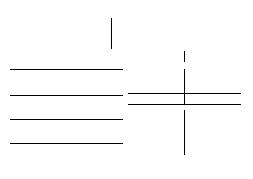
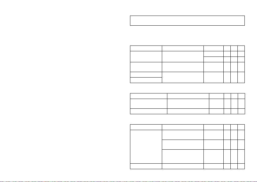
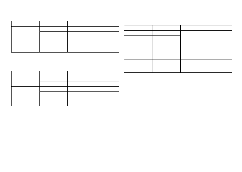
Device types
For the following symptoms/expectations, the following device types are indicated:
Symptom/exp ectation SR DR HF
Disorientation due to bradycardia x x x
Presyncope xxx
Benefit from resynchronization of the right and
left ventricles
Syncope xxx
Pacing modes
For the following symptomatic, the following pacing modes are indicated:
Symptom/expectation Pacing mode
Sick sinus syndrome Dual-chamber pacing
Chronic, symptomatic second and third-degree AV block Dual-chamber pacing
Adams-Stokes syndrome Dual-chamber pacing
Symptomatic bilateral bundle branch block when tachy-
arrhythmia and other causes have been ruled out
•
Chronotropic incompetence
•
Benefit from increased pacing rate with physical
activity
Sinus node dysfunction in the presence of normal AV and
intraventricular conduction
Bradycardia in conjunction with the following:
•
Normal sinus rhythms with only rare episodes of
AV block or sinus arrest
•
Chronic atrial fibrillation
•
Severe physical disability
MR conditional
ProMRI® labeled MRI conditional pacemakers are safe for use in the MRI environment
when used in conjunction with a c omplete MRI conditional pacing system and according
to the instructions given in the ProMRI® manual.
Dual-chamber pacing
R mode or CLS
Atrial pacing
Ventricular pacing
Contraindications
Guidelines
No contraindications are known for the implantation of multifunctional singlechamber, dual-chamber, or triple-chamber pacemakers, provided differential diagnostics precedes implantation according to the appropriate guidelines and no modes or
parameter combinations are configured that pose a risk to the patient.
x
Pacing modes and parameters
The compatibility and effectiveness of parameter combinations must be checked and,
as the case may be, adapted after programming.
Set of facts Contraindicated pacing mode
Additionally implanted ICD Unipolar pacing
Set of facts Inappropriate pacing mode
Chronic atrial tachycardia, chronic atrial
fibrillation or flutter
Poor tolerance of pacing rates above the
basic rate, e.g., angina pectoris
AV conduction disorder Atrial single-chamber pacing
Failing AV conduction
Set of facts Adapt parameters
Slow retrograde conduction after ventricular pacing: Risk of pacemaker-mediated
tachycardia
Poor tolerance of pacing rates above the
basic rate, e.g., angina pectoris
2
Atrial-controlled modes (DDD, VDD, AAI)
•
Extend atrial refractory period (ARP)
and/or:
•
Shorten AV delay
•
Rarely:
Program to DDI, DVI or VVI
•
Lower atrial upper rate
•
Lower maximum sensor rate
•
Deploy atrial overdrive pacing
Page 4
System Overview
Device family
This device family consists of single-chamber, dual-chamber and triple-chamber
devices with or without Home Monitoring. Not all device types are available in every
country.
The following device variants are available:
Device type Variant with
Single-chamber Evity 6 SR-T, Evity 8 SR-T —
Dual-chamber Evity 6 DR-T, Evity 8 DR-T —
Triple-chamber Evity 8 HF-T, Evity 8 HF-T QP —
Device
The device's housing is made of biocompatible titanium, welded from the outside and
therefore hermetically sealed. The ellipsoid shape facilitates ingrowth into the pectoral
muscle area. The housing serves as an antipole in the case of unipolar lead configuration.
Lead connections
BIOTRONIK provides pacemakers with headers for different standardized lead connections:
•
IS-1
•
IS-1/IS4
Note:
•
A device's IS-1 connector port must only be used for connecting leads with
an IS-1 connector that conform to ISO 5841-3.
•
A device's IS4 connector port must only be used for connecting leads with
an IS4 connector that conform to ISO 27186.
Note:
•
Only quadripolar leads must be connected to the IS4 connector on device
type HF QP with IS4.
en • English
Home Monitoring
Suitable leads must comply with the norms:
The device and leads have to match.
Variant without
Home Monitoring
Note:
Use only adapters approved by BIOTRONIK for leads with different connections.
•
If you have any questions concerning the compatibility of other manufacturers'
leads, please contact BIOTRONIK.
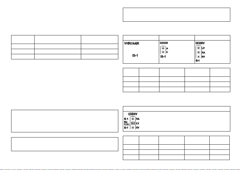
IS-1
The device labeling provides information pertaining to the connection assignment:
SR DR HF
Connector
Lead
port
connector
A/RA IS-1 Unipolar, bipolar Atrium DR, HF
V/RV IS-1 Unipolar, bipolar Right ventricle SR, DR, HF
LV IS-1 Unipolar, bipolar Left ventricle HF
IS-1/IS4
The device labeling provides information pertaining to the connection assignment:
HF QP
Connector
Lead
port
connector
RA IS-1 Unipolar, bipolar Atrium HF QP
RV IS-1 Unipolar, bipolar Right ventricle HF QP
LV IS4 Unipolar, bipolar Left ventricle HF QP
Configuration Implantation site Device type
Configuration Implantation site Device type
3
Page 5

Leads
BIOTRONIK leads are sheathed in biocompatible silicone. They can be flexibly maneuvered, are stable long-term, and are equipped for active or passive fixation. They are
implanted using a lead introducer set. Some leads are coated with polyurethane which
is known to increase the gliding properties for the lead. Leads with steroids reduce
inflammatory processes. The fractal design of the leads allows for low pacing
thresholds, high pacing impedance, and a low risk of oversensing.
BIOTRONIK provides adapters to connect already implanted leads to new devices.
Telemetry
Telemetric communication between the device and the programmer can be carried out
following initialization either by applying the programming head (PGH) to the device or
by using wireless wandless telemetry in the programmer.
Programmer
Using the programmer, the pacing thresholds can be determined and all tests can
be performed during implantation and in-office follow-up. In addition to this, the
programmer is used to set mode and parameter combinations, as well as for interrogation and saving of data from the device. Leadless ECG, IEGM, markers and functions are
displayed simultaneously on the color display.
Modes
The mode setting depends on the individual diagnosis:
Device type Modes Standard
SR
DR
•
VVI-CLS(8 series only)
•
VVIR, V00R, AAIR, A00R
•
VVI, VVT, V00, AAI, AAT, A00
•
OFF
•
VVI-CLS; DDD-CLS(8 series only)
•
DDD-ADI, DDDR-ADIR (6 and 8 series)
•
DDDR, DDIR, DVIR, D00R, VDDR, VDIR
•
VVIR, V00R, AAIR, A00R
•
DDD, DDT, DDI, DVI, D00, VDD, VDI
•
VVI, VVT, V00, AAI, AAT, A00
•
OFF
VVIR
DDDR
Device type Modes Standard
HF (QP)
•
(8 series)
Note:
Home Monitoring is possible in all modes.
The OFF mode only functions temporary, i.e. during a test.
NBG codes
AAIR or VVIR is the NBG code for the antibradycardia mode of the single-chamber
device:
A/V Pacing in the atrium or ventricle
A/V Sensing in the atrium or ventricle
I Pulse inhibition in the atrium and ventricle
R Rate adaptation
DDDR is the NBG code for the antibradycardia mode of the dual-chamber device:
D Pacing in the atrium and ventricle
D Sensing in the atrium and ventricle
D Pulse inhibition and pulse triggering
R Rate adaptation
DDDRV is the NBG code for the antibradycardia mode of the triple-chamber device:
D Pacing in the atrium and ventricle
D Sensing in the atrium and ventricle
D Pulse inhibition and pulse triggering
R Rate adaptation
V Multisite pacing in both ventricles
VVI-CLS, DDD-CLS
•
DDD-ADI, DDDR-ADIR
•
DDDR, DDIR, DVIR, D00R, VDDR, VDIR
•
VVIR, V00R, AAIR, A00R
•
DDD, DDT, DDI, DVI, D00, VDD, VDI
•
VVI, VVT, V00, AAI, AAT, A00
•
OFF
DDDR
4
Page 6
BIOTRONIK Home Monitoring
In addition to effective pacing therapy, BIOTRONIK provides a complete therapy
management system:
•
With Home Monitoring, diagnostic and therapeutic information and technical data
are automatically sent to a stationary or mobile transmitter via an antenna in the
device header. The data are encrypted and sent from the transmitter to the
BIOTRONIK Service Center via the cellular phone network.
•
The received data are deciphered and evaluated. Each physician can set the criteri a
for evaluation to be used for each patient and can configure the time of notification
via e-mail, SMS or fax.
•
A clear overview of the results of this analysis is displayed for the attending physicians on the protected internet platform Home Monitoring Service Center (HMSC).
•
Data transmission from the device is performed with a daily device message.
•
Device messages, which indicate special events in the patient's heart or in the
device, are forwarded with the following message.
•
A test message can be initiated at any time using the programmer to immediately
check the Home Monitoring function.
Order numbers for Evity
The devices can be obtained as follows:
Evity 6 SR-T 407161 Evity 8 DR-T 407146
Evity 6 DR-T 407149 Evity 8 HF-T 407140
Evity 8 SR-T 407158 Evity 8 HF-T QP 407139
Package contents
The storage package includes the following:
•
Sterile packaging with device
•
Serial number label
•
Patient ID card
•
Warranty booklet
Note:
The technical manual pertaining to the device is either included in hard copy
form in the storage package or in digital form on the internet.
®
The sterile packaging includes the following:
•
Device
•
Screwdriver
Diagnostic and Therapy Functions
General overview
All the systems have extensive features that allow quick diagnosis and delivery of safe
therapy for bradycardia conditions.
•
Automatic functions make it easy and fast to implant, configure, and check the
pacemaker.
•
Auto-initialization after implantation: The device recognizes the implanted leads
autonomously and sets the polarity. The automatic functions of the software are
activated after 10 min.
Diagnostic functions
•
Data from the last interrogations and follow-ups are recorded as well as
arrhythmia episodes; they are stored together with other data to assess the state of
both the patient and the device at any time.
•
Continuous automatic below-threshold impedance measurements are performed
in the device independent of the pacing pulse in order to check the lead for proper
functioning.
•
Once a telemetry connection has been established during a test procedure in
an in-office follow-up, the IEGM is displayed with markers.
Antibradycardia pacing
•
Sensing: The amplitudes of the P and R waves are measured in the implanted
device fully automatically and permanently to record varying amplitudes. The
sensitivity for the atrium and ventricle is adapted automatically on an ongoing
basis. The measurement data are averaged and the trend can be displayed.
•
Pacing thresholds: Pacing thresholds are automatically identified in the device:
In single-chamber devices the right ventricular, in dual-chamber devices the atrial
and right ventricular, in triple-chamber devices the atrial, right and left ventricular
pacing thresholds. Capture control adjusts the pulse amplitudes in such a way that
every change of the pacing threshold results in the patient being paced at an
optimal amplitude.
en • English
5
Page 7

•
Timing: Pacing in the atrium is checked particularly carefully in dual and triplechamber devices by an automatic adaptation of the atrial refractory period in order
to avoid pacemaker-mediated tachycardia (Auto PVARP function: The postventricular atrial refractory period is adapted automatically).
•
Additional, special form of rate adaptation with devices from the 8 series: An
increased cardiac output requirement is detected using physiological impedance
measurement. The measuring principle is based on contractile changes (inotropy)
of the myocardium (CLS function: Closed Loop Stimulation). Rate adaptation is
automatically initialized and optimized in CLS mode.
•
Ventricular pacing suppression: Unnecessary ventricular pacing is avoided by
promoting intrinsic conduction (Vp suppression function). The device can adapt
itself to conduction changes. In the case of intrinsic conduction, the device switches
from a DDD(R) to an ADI(R) mode.
•
8 series: In the course of the follow-up, an automatic test of the AV delay is
performed to improve the heart performance. AV delays are calculated; the
optimum values can be applied.
Resynchronization therapy
Triple-chamber devices have functions to configure different VV delays in order to
resynchronize the ventricles.
•
Capture Control is also available for the left ventricle with automated tracking of
the pacing threshold or automatic threshold monitoring (ATM) for trend analysis.
•
To ensure that no additional surgery is necessary in case of a left-sided increase of
pacing threshold or undesired phrenic nerve stimulation, di fferent pacing polarities
can be set for the left ventricular lead with a triple-chamber device. Up to
13 vectors can be used with the HF QP device type.
•
8 series: With the QP device type, the LV vector test provides a fast measurement of
the pacing threshold, the phrenic nerve pacing threshold and the pacing impedance. The relative influence on the service time is also displayed. The measurement
results are evaluated automatically so that the optimal pacing polarity can be set.
The short RV-LV conduction test also supports the selection.
•
An additional diagnostic function with biventricular pacing: Variability of the heart
rate, patient activity, and thoracic impedance are monitored on a continual basis.
Programs
There are two types of therapy programs:
•
Default parameters are offered for the most common indications (ProgramConsult
function).
•
Individual settings can be saved in 3 individual therapy programs.
ProMRI devices recognize magnetic resonance imaging devices
The static magnetic field of magnetic resonance imaging devices is reliably recognized
with the aid of a sensor. This sensor can be activated for a maximum of 14 days using
the MRI AutoDetect function during an interrogation.
If the patient comes near a magnetic resonance imaging device within the time set, the
implanted device recognizes the static magnetic field and automatically activates the
preset MRI program. Reprogramming to the permanent program occurs also automatically after leaving the imaging device.
Home Monitoring functi ons
The device automatically sends information to the transmitter once a day. In addition to
this, test messages can be initiated using the programmer. Important medical information includes, among others, the following:
•
Ongoing atrial and ventricular arrhythmia
•
Parameters relevant to leads in the atrium and ventricle: Thresholds, sensing
amplitudes, impedances
•
Current statistics on bradycardia therapy
•
Individually adjustable timing interval for device messages which provide additional
information pertaining to the device messages
•
IEGM online HD® with up to 3 high definition channels
•
Transmission of these IEGM recordings with device messages
6
Page 8

2 General Safety Instructions
W
CAUTION
Safety information
Cardiac electrotherapy is subject to special operating conditions and possible complications and risks.
•
Please take all precautionary measures carefully into account.
Operating Conditions
Technical manuals
The following technical manuals provide information about usage of the device
systems:
— Technical manual for the device
— Technical manual for the HMSC
— Technical manuals for leads
— Technical manuals for the programmer and its accessories
— Technical manuals for the user interface
— Technical manuals for cables, adapters and accessories
•
Technical manuals are either included in hard copy form in the storage package or
in digital form on the internet:
manuals.biotronik.com
•
Follow all relevant technical manuals.
•
Keep technical manuals for later use.
Care during shipping and storage
•
Devices are not to be stored close to magnets or sources of electromagnetic interference.
•
Note the effects of the storage period; see Battery Data.
Temperature
Extremely low and high temperatures affect the service time of the battery in the
device.
•
Permitted for shipping and storage:
–10°C to +45°C
Sterile delivery
The device and the screwdriver have been gas-sterilized. Sterility is guaranteed only if
the blister and quality control seal have not been damaged.
Sterile packaging
The device and screwdriver are packaged in 2 separately sealed blisters. The inner
blister is also sterile on the outside so that it can be transferred in a sterile state during
implantation.
Single use only
The device and screwdriver are intended for single use only.
•
Do not use the device if the package is damaged.
•
The device must not be resterilized and reused.
Possible Complications
General information on medical complications
Complications for patients and device systems generally recognized among practitioners also apply to BIOTRONIK devices.
•
Normal complications may include fluid accumulation within the device pocket,
infections, or tissue reactions. Primary sources of complication information include
current scientific and technological knowledge.
•
It is not possible to guarantee the efficacy of antiarrythmia therapy, even if the
programs have proven successful during tests or subsequent electrophysiological
examinations. In rare cases the set parameters can become ineffective.
In particular it is inevitable that tachyarrhythmias may be induced.
Skeletal myopotentials
Bipolar sensing and control of sensitivity are adapted by the device to the rate range
of intrinsic events so that skeletal myopotentials are usually not sensed. Skeletal
myopotentials can nonetheless be classified as intrinsic events especially with
a unipolar configuration and/or very high sensitivity and, depending on the interference,
may cause inhibition or antiarrhythmia therapy.
Nerve and muscle stimulation
A device system consisting of a unipolar lead and an uncoated device may result in
undesirable pacing of the diaphragm in the case of an initial or permanent high setting
of the pulse amplitude.
en • English
7
Page 9

Possible technical failures
Technical failure of a device system cannot be entirely ruled out. Possible causes may
include the following:
•
Lead dislodgement
•
Lead fracture
•
Insulation defects
•
Device component failures
•
Battery depletion
Electromagnetic interference (EMI)
Any device can be sensitive to interference, for example, when external signals are
sensed as intrinsic rhythm.
•
BIOTRONIK devices have been designed so that their susceptibility to EMI is
minimal.
•
Due to the intensity and variety of EMI, there is no guarantee for safety. It is
generally assumed that EMI produces only minor symptoms in patients - if any.
•
Depending on the pacing mode and the type of interference, sources of interference
may lead to pulse inhibition or triggering, an increase in the sensor-dependent
pacing rate or asynchronous pacing.
•
Under unfavorable conditions, for example during diagnostic or therapeutic procedures, interference sources may induce such a high level of energy into the pacing
system that the cardiac tissue surrounding the lead tip is damaged.
Device behavior in case of EMI
In the case of electromagnetic interference or undesired myopotentials, the device
paces asynchronously for the duration of the time that the interference rate is
exceeded.
Static magnetic fields
The pacemaker switches to magnet response from a field strength > 1.0 mT.
Possible Risks
Procedures to avoid
The following procedures must be avoided as they may cause harm to the patient or
damage the device and, as a result, put the system functionality at risk:
•
Therapeutic ultrasound
•
Transcutaneous electrical nerve stimulation
•
Hyperbaric oxygen therapy
•
Applied pressures higher than normal pressure
Potentially risky therapeutic and diagnostic procedures
If electrical current from an external source is conducted through the body for
diagnostic or therapeutic purposes, then the device can be subjected to interference
and the patient placed at risk.
Arrhythmia or ventricular fibrillation can be induced during diathermic procedures
such as electrocautery, HF ablation or HF surgery. For example, damaging pressure
levels may arise during lithotripsy. Influences on the device are not always immediately
clear.
If potentially risky procedures cannot be avoided, the following should be observed at
all times:
•
Electrically insulate patients.
•
Switch the pacemaker function to asynchronous modes if needed.
•
Do not introduce energy near the device system.
•
Check the peripheral pulse of the patient.
•
Monitor the patient during and after every intervention.
External defibrillation
The device is protected against the energy that is normally induced by external defibrillation. Nevertheless, any implanted device may be damaged by external defibrillation.
Specifically, the current induced in the implanted leads may result in necrotic tissue
formation close to the electrode/tissue interface. As a result, sensing properties and
pacing thresholds may change.
•
Place adhesive electrodes anterior-posterior or perpendicular to the axis formed
by the device to the heart at least 10 cm away from the device and from implanted
leads.
8
Page 10
Radiation therapy
The use of radiation therapy must be avoided due to possible damage to the device and
the resulting impaired functional safety. If this type of therapy is to be used anyway,
prior risk/benefit analysis is absolutely necessary. The complexity of influencing
factors such as different sources of radiation, a variety of devices and therapy conditions makes it impossible to issue directives that guarantee radiation therapy without
an impact on the device. The EN 45502 standard pertaining to active implantable
medical devices requires the following measures during the administration of
therapeutic ionizing radiation:
•
Adhere to instructions for potentially risky therapeutic and diagnostic procedures.
•
Shield device against radiation.
•
After applying radiation, double-check the device system to make sure it is
functioning properly.
Note:
Please contact BIOTRONIK with questions on the risk/benefit analysis.
Magnetic resonance imaging
Magnetic resonance imaging must be avoided due to the associated high frequency
fields and magnetic flux density: Damage or destruction of the device system by strong
magnetic interaction and damage to the patient by excessive warming of the body
tissue in the area surrounding the device system.
Under certain conditions and when maintaining mandatory measures to protect the
patient and the device system, magnetic resonance imaging can be performed.
BIOTRONIK devices with the "MR conditional" function bear the identification ProMRI.
•
The ProMRI manual – MR conditional device systems – contains detailed information on safely conducting an MRI.
—
Download the digital manual from the web site:
manuals.biotronik.com
—
Order the printed manual at BIOTRONIK.
•
Does approval as "MR conditional" apply in your country or region?
Ask for current information at BIOTRONIK.
3 Implantation
Implantation Procedure
Having parts ready
The following parts that correspond to the requirements of the EC Directive 90/385/EEC
are required:
•
Device with screwdriver from BIOTRONIK
•
BIOTRONIK leads and lead introducer set
—
Single-chamber device: unipolar or bipolar lead for the right ventricle
—
Dual-chamber device: one unipolar or bipolar lead each for the atrium and for
the right ventricle
—
Triple-chamber device: an additional unipolar, bipolar, or quadripolar LV lead
•
Approved connections are IS-1 and IS4: Use only adapters approved by BIOTRONIK
for leads with different connections or leads from other manufacturers.
•
BIOTRONIK programmer (with integrated wandless telemetry or with separate
SafeSync Module) and approved cables
•
External multi-channel ECG device
•
Keep spare parts for all sterile components.
Keeping an external defibrillator ready
In order to be able to respond to unforeseeable emergencies or possible technical
failures of the device:
•
Keep an external defibrillator and paddles or adhesive electrodes ready.
Unpacking the device
W
WARNING
Inadequate therapy due to defective device
If an unpacked device is dropped on a hard surface during handling, electronic parts
could be damaged.
•
Use a replacement device.
•
Return the damaged device to BIOTRONIK.
en • English
9
Page 11

•
Peel the sealing paper off of the outer blister at the marked position in the direction
indicated by the arrow. The inner blister must not come into contact with persons
who have not sterilized their hands or gloves, nor with non-sterile instruments.
•
Use the gripping tab on the inner blister to remove it from the outer blister.
•
Peel the sealing paper off of the sterile inner blister at the marked position in the
direction indicated by the arrow.
Note:
The device is disabled on delivery and can be implanted immediately after
unpacking without manual activation.
Checking parts
Damage to any of the parts can result in complications or technical failures.
•
Check for damage before and after unpacking all parts.
•
Replace damaged parts.
Implantation site
In general, the pacemaker is implanted subcutaneously or subpectorally, depending on
the lead configuration as well as the anatomy of the patient.
Overview: Implanting
1 Shape the device pocket and prepare the vein.
2 Implant the leads and perform measurements.
3 Connect device and leads.
4 Insert the device.
The device starts auto-initialization on its own.
5 Guide the fixation suture through the opening in the header and fixate the device
in the prepared device pocket.
6 Close the device pocket.
7 Prior to testing and configuration, wait for the successful completion of
automatic device initialization.
Note:
If necessary, the device can also be programmed before or during auto-initial-
ization.
Avoid damage to the header
Set screws must be tightened or loosened with care.
•
Loosen set screws with the supplied screwdriver. Use only BIOTRONIK screwdrivers with torque control!
•
If lead revision is necessary, re-order sterile screwdrivers from BIOTRONIK.
Preventing short circuits in the header
W
WARNING
Short circuit due to open lead connector ports
Connector ports in the header which are open and thus not electrolyte-proof may
cause undesired current flows to the body and penetration of body fluid into the
device.
•
Close unused connector ports with blind plugs.
Keeping distance between leads
W
WARNING
Inadequate therapy
Insufficient lead spacing or inappropriate lead positioning may lead to far-field
sensing.
•
Leads must not contact each other. Position the tip and ring of newly implanted
leads with a sufficient distance from old implanted leads.
Connecting the lead connector to the device
1 Remove stylets and stylet guides.
2•Connect the unipolar or bipolar IS-1 lead connector for the right ventricle to
RV.
•
Connect the unipolar or bipolar IS-1 lead connector atrium to A.
•
Connect the unipolar or bipolar IS-1 or the quadripolar IS4 lead connector
for the left ventricle to LV.
3 Push the lead connector into the header without bending the conductor until the
connector tip becomes visible behind the set screw block.
10
Page 12
4 If the lead connector cannot be inserted completely, the set screw may be
protruding into the drill hole of the set screw block. Carefully loosen the set
screw without completely unscrewing it, so that it does not become tilted upon
retightening.
5 Use the screwdriver to perpendicularly pierce through the slitting in the center
of the silicone plug until it reaches the set screw.
6 Turn the set screw clockwise until the torque control starts (you will hear
a clicking sound).
7 Carefully withdraw the screwdriver without retracting the set screw.
•
When the screwdriver is withdrawn, the silicone plug automatically seals the
lead connection safely.
Applying the programming head
The programming head (PGH) features a diagram of the device. This is used to assist in
positioning the head to ensure proper telemetry.
•
Make sure the PGH is positioned correctly.
Establishing wandless telemetry
The programmer must be no less than 20 cm and no more than 3 m from the device;
ideally there should be no hindrances between the patient and the programmer.
•
Switch on wandless telemetry on the programmer.
•
Apply the programming head for about 2 s until successful initialization is displayed
on the programmer:
The wandless telemetry symbol is displayed in the navigator and the
signal strength is displayed in the status line.
•
Remove the programming head.
Auto-initialization
Auto-initialization begins automatically once the first connected lead is sensed.
Auto-initialization is usually terminated 10 minutes after connection of the first lead. If
no other program has been transferred in the meantime, the device subsequently
works with active automatic functions in the factory settings or with the preset program
of the user.
Manual setting of the lead polarity or measurement of lead impedances is not necessary.
Note:
After auto-initialization, all parameters are activated as in the standard
program.
Behavior during auto-initialization
•
During transmission of a permanent program:
Auto-initialization is terminated and the transferred program is active.
•
During testing:
Tests cannot be performed during auto-initialization; stop it beforehand. Auto-
initialization will not be continued upon completion of the test.
Precautionary Measures while Programming
W
CAUTION
Safety information
The programming of device systems requires special precautions.
•
Please carefully take all precautionary measures into account.
Checking the device system
•
After auto-initialization, perform a follow-up to see if the device system is
functioning properly.
•
Perform a pacing threshold test to determine the pacing threshold.
Performing standard tests and monitoring the patient
Critical conditions can occur for the patient even during standard tests due to
inadequate parameter settings or interrupted telemetry.
•
Ensure sufficient patient care even during tests.
•
After the threshold test, check to determine whether the threshold is clinically and
technically justifiable.
•
Continuously monitor the ECG and the patient's condition.
•
Cancel testing if necessary.
en • English
11
Page 13

Do not interrupt wandless telemetry during a treatment
Disconnecting the SafeSync Module from the programmer can result in interference
with or termination of the SafeSync wandless telemetry.
•
Do not disconnect the SafeSync Module from the programmer.
•
Do not take the Operation Module off the ICS 3000.
Cancelling telemetry
Programmer interference or interrupted telemetry during performance of temporary
programs (follow-up tests) can result in inadequate pacing of the patient. This is the
case if the programmer can no longer be operated due to a program error or
a defective touch screen and therefore the temporary program cannot be terminated.
Under these circumstances, it is helpful to cancel telemetry, in which case the device
automatically switches to the permanent program.
•
In the case of telemetry with PGH: lift the programming head by at least 30 cm.
•
In the case of wandless telemetry: switch off and reposition the programmer.
•
Turn off possible sources of interference.
Avoiding critical parameter settings
No modes and parameter combinations that pose a risk to the patient should be set.
•
Prior to setting rate adaptation, determine the patient's capacity for strain.
•
Check compatibility and effectiveness of parameter combinations after making
settings.
Manually setting lead polarity
Due to the risk of an entrance/exit block, bipolar lead polarity (sensing/pacing) should
only be set if bipolar leads are implanted.
Setting sensing
Manually set parameters can be unsafe. For example, unsuitable far-field protection
may impede sensing of intrinsic pulses.
•
Use automatic sensitivity control.
Setting the sensitivity
A value set to < 2.5 mV/unipolar for device sensitivity may result in noise caused by
electromagnetic fields.
•
Therefore, it is recommended that a value of ≥ 2.5 mV/unipolar be set according to
paragraph 28.22.1 of the EN 45502-2-1 standard. Setting sensitivity values
< 2.5 mV/unipolar requires explicit clinical need. Values like this must only be set
and retained with physician supervision.
Note:
Sensitivity in the atrium meets the requirements for electromagnetic compatibility as long as it is ≥ 0.3 mV/bipolar. Measures must be taken to assure interferencefree therapy if more sensitive values < 0.3 mV/bipolar are set.
Preventing device-induced complications
BIOTRONIK devices are equipped with several functions to prevent device-induced
complications to the greatest extent possible:
•
Measure the retrograde conduction time.
•
If the function is not yet automatically set: activate PMT protection.
•
Set the VA criterion: The aim is to set a VA criterion that is longer than the longest
measured retrograde conduction time.
Preventing conduction of atrial tachycardia
BIOTRONIK devices are equipped with several functions to prevent conduction of atrial
tachycardia to the ventricle(s):
•
Set Mode Switching for indicated patients.
•
Set the upper rate and the refractory periods to prevent abrupt ventricular rate
switching.
•
Prefer Wenckebach response and avoid 2:1 behavior.
•
Set all parameters so as to prevent constant changing between atrial and ventricular-controlled modes.
Phrenic nerve stimulation that cannot be terminated
With LV pacing, chronic phrenic nerve stimulation can in rare cases not be terminated
by reprogramming the available left ventricular pacing configurations or by other
measures.
•
Possibly set a right ventricular mode both in the permanent program and for
Mode Switching.
Avoiding risks in the case of exclusive left ventricular pacing
Lead dislodgement in the case of exclusive left ventricular pacing could pose the
following risks: loss of ventricular pacing as well as induction of atrial arrhythmia.
•
Consider sensing and pacing parameters with reference to loss of therapy.
•
Exclusive left ventricular pacing is not recommended for patients who depend on
the device.
12
Page 14

•
Take possible interruption of automatic Active Capture Control into consideration.
•
In the case of follow-ups and threshold tests, take loss of synchronized ventricular
pacing into consideration.
•
Mode Switching does not allow exclusive left ventricular pacing; consider the
consequences when setting Mode Switching parameters.
If an ICD is implanted at the same time, do not permit unipolar pacing
If an ICD is implanted in addition to a pacemaker and a lead fail ure occurs, it is possible
to switch to unipolar pacing after resetting the pacemaker or using the automatic lead
check. As a result, the ICD could falsely inhibit or trigger tachyarrhythmiatherapy
activity.
•
Unipolar leads are not permitted in this configuration.
Recognizing lead failure
Automatic impedance measurement is always switched on.
•
Impedance values that indicate technical failure of a lead are documented in the
event list.
Consider power consumption and service time
The pacemaker permits programming of high pulse amplitudes with long pulse widths
at high rates to be able to adequately treat even rare diagnoses. In combination with
low lead impedance, this results in a very high level of power consumption.
•
When programming large parameter values, take into account that the replacement indication ERI will be reached very early because the service time of the
battery may be reduced to less than 1 year.
Home Monitoring: The CardioMessenger should be relatively close to the patient; if it is
too far away, the device constantly seeks and consumes more power than necessary.
•
Home Monitoring ON reduces the service time by approximately 15% in single- and
dual-chamber devices and by approximately 10% in triple-chamber devices.
Wandless telemetry: 15 minutes of usage reduces the service time by approximately
7 days.
•
Do not establish unnecessary wandless telemetry.
•
After 5 min without input, the device switches to the economy mode.
•
Check the battery capacity of the device at regular intervals.
Magnet Response
Programming head application
When the programming head is applied, time remains for device interrogation before
the device switches back to the previously set permanent therapy mode. The same
applies to programming head application to establish wandless telemetry contact.
Magnet response in standard program
Applying a magnet or the programming head can result in an unphysiological rhythm
change and asynchronous pacing. The magnet response is set as follows in the
standard program of BIOTRONIK pacemakers:
•
Asynchronous:
For the duration of the magnet application – mode D00 (where applicable V00 / A00)
without rate adaptation;
Magnet rate: 90 bpm
•
Automatic:
For 10 cycles – mode D00, subsequently mode DDDR;
Magnet rate: 10 cycles with 90 bpm, subsequently set basic rate
•
Synchronous:
Mode DDDR (VVIR as the case may be);
Magnet rate: set basic rate
Note:
See also the replacement indication information for magnet response at ERI.
Magnet application by patients
If patients are performing their own magnet application, the synchronous magnet
response must have been programmed. Patients should also know the following:
•
When may the magnet be used?
In cases of severe dizziness and indisposition.
•
How long is the magnet placed on the pacemaker?
1 to 2 s.
•
What happens when the magnet is applied?
The IEGM of the last 10 seconds is stored.
•
What has to happen after magnet application?
The patient has to contact the physician for a follow-up.
en • English
13
Page 15
Follow-up
Follow-up intervals
Follow-ups must be performed at regular, agreed intervals.
•
Following the lead ingrowth phase, approximately 3 months after implantation,
the first follow-up should be carried out by the physician using the programmer
(in-office follow-up).
•
The next in-office follow-up should be carried out once a year and no later than
12 months after the last in-office follow-up.
Follow-up with BIOTRONIK Home Monitoring®
Monitoring using the Home Monitoring function does not serve to replace regular
in-office appointments with the physician required for other medical reasons.
Follow-up supported by Home Monitoring can be used to functionally replace in-office
follow-up under the following conditions:
•
The patient was informed that the physician must be contacted if symptoms worsen
or if new symptoms arise despite the use of the Home Monitoring function.
•
Device messages are transmitted regularly.
•
The physician decides whether the data transmitted via Home Monitoring with
regard to the patient's clinical condition as well as the technical state of the device
system are sufficient. If not, an in-office follow-up has to be carried out.
Possible early detection due to information gained via Home Monitoring may necessitate an additional in-office follow-up. For example, the data may indicate at an early
stage lead problems or a foreseeable end of service time (ERI). Furthermore, the data
could provide indications of previously unrecognized arrhythmias or regarding modification of therapy by reprogramming the device.
Follow-up with the programmer
Use the following procedure for in-house follow-up:
1 Record and evaluate the ECG.
2 Interrogate the device.
3 Evaluate the status and automatically measured follow-up data.
4 Check the sensing and pacing functions.
5 Manually perform standard tests if necessary.
6 Possibly evaluate statistics and IEGM recordings.
7 Possibly adjust program functions and parameters.
8 Transmit the permanent program to the implanted device.
9 Print and document follow-up data (print report).
10 Finish the follow-up for this patient.
Patient Information
Patient ID card
A patient ID card is included in delivery.
•
Provide the patient with the patient ID card.
•
Request that patients contact the physician in case of uncertainties.
Prohibitive signs
Premises with prohibitive signs must be avoided.
•
Draw the patient's attention to prohibitory signs.
Possible sources of interference
Electromagnetic interference should be avoided in daily activities. Sources of interference should not be brought into close proximity of the device.
•
Draw the patient's attention to special household appliances, security checkpoints,
anti-theft alarm systems, strong electromagnetic fields, cellular phones, and
transmitters among other things.
•
Request patients to do the following:
—
Use cellular phones on the opposite side of their body from the device.
—
Keep the cellular phone at least 15 cm away from the device both during use
and when stowing.
Replacement Indications
Possible charging status
The time span from the beginning of service (BOS) to elective replacement indication
(ERI) is determined by, among others, the following:
•
Battery capacity
•
Lead impedance
•
Pacing program
•
Pacing to inhibition ratio
•
Pacemaker circuit properties
14
Page 16
The following are the defined pacemaker operational statuses:
•
BOS: Beginning of Service: > 90%
•
ERI: Elective Replacement Indication (i.e., RRT: Recommended Replacement Time)
•
EOS: End of Service
ERI activation
ERI detection is automatically activated after the following events:
•
Successful auto-initialization
ERI display
ERI is displayed as follows:
•
On the programmer after interrogation of the pacemaker
•
By a defined decrease in the basic rate as well as the magnet rate
Rate decrease
The decrease of basic rate and magnet rate is defined as follows:
•
In the following modes, the pacing rate decreases by 11%:
DDD(R); DDT; D00(R); VDD(R); VDI(R); VVI(R); VVT; AAI(R); AAT; A00(R)
•
In the modes DDI(R) and DVI(R), only the VA interval is extended by 11%. This
reduces the pacing rate by up to 11%, depending on the configured AV delay.
Change of the mode with ERI
This change depends on the mode which is set. It is displayed on the programmer.
•
Single-chamber modes: VVI
•
Dual-chamber modes: VDD
•
Triple-chamber modes: Dual-chamber pacing, one biventricular setting is kept
Deactivated functions with ERI
The following functions are deactivated:
•
Atrial pacing
•
Night program
•
Rate adaptation
•
Atrial and ventricular capture control
•
Rate fading
•
Atrial overdrive pacing
•
IEGM recordings
•
Statistics
•
Home Monitoring
•
Rate hysteresis
•
Ventricular pacing suppression
Magnet response at ERI
After reaching ERI, pacing is performed as follows after applying the magnet or
programming head:
Magnet
response
Automatic Asynchronous with 80 bpm Synchronous with basic rate
Asynchronous Asynchronous with 80 bpm Asynchronous with 80 bpm
Synchronous Synchronous with basic rate
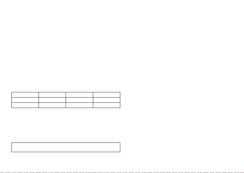
Expected service times after ERI
The information is based on the following:
•
Lead impedance of 500 Ω or 600 Ω
•
100% pacing
•
Interval from ERI to EOS for the single-chamber device in AAI(R)/VVI(R) mode, for
the dual and triple-chamber device in DDD(R) mode
•
Standard program with both high and low pacing energy
•
Data of the battery manufacturer (see the battery data)
110 bpm
4.6 V
1.5 ms
500 Ω
Mean value: 8 months
Minimum value: 6 months—Minimum value: 6 months—Minimum value: 6 months
Cycles 1 to 10 After 10th cycle
reduced by 11%
reduced by 11%
30 bpm
0.2 V
0.1 ms
500 Ω
70 bpm
2.5 V
0.4 ms
500 Ω
Synchronous with basic rate
reduced by 11%
70 bpm
5.0 V
0.4 ms
500 Ω
60 bpm
2.5 V
0.4 ms
600 Ω
60 bpm
5 V
0.4 ms
600 Ω
en • English
15
Page 17
Explantation and Device Replacement
Explantation
•
Disconnect the leads from the header.
•
Remove the device and, if necessary, leads using state-of-the-art technology.
•
Explants are biologically contaminated and must be disposed of safely due to risk of
infection.
Device replacement
The following applies to leads from a previous device that are intended for further use:
•
Check the leads prior to connecting to the new device.
If, upon replacing the device, already implanted leads are no longer used but left in the
patient, then an additional uncontrolled current path to the heart can result.
•
Isolate unused lead connectors and close unused connector ports.
Basic principles:
•
The device must not be resterilized and reused.
Cremation
Devices should not be cremated.
•
Explant the device before the cremation of a deceased patient.
Disposal
BIOTRONIK takes back used products for the purpose of environmentally safe disposal.
•
Clean the explant with a solution of at least 1% sodium hypochlorite.
•
Rinse with water.
•
Fill out explantation form and send to BIOTRONIK together with the cleaned device.
4 Parameters
Note:
Unless described separately, information for device type HF also applies to
device type HF QP.
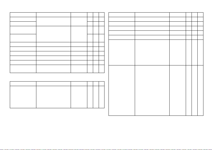
Timing
Basic rate day/night
Parameter Range of values Standard SR DR HF
Basic rate 30 ... (5) ... 100 ... (10)
Night rate OFF; 30 ... (5) ... 100 ... (10)
Night begins 00:00 ... (10 min) ...
Night ends
Rate hystereses
Parameter Range of values Standard SR DR HF
Hysteresis OFF; -5 ... (-5) ... -25 ... (-20)
Repetitive/ search cycles OFF; ON OFF x x x
AV delay
Parameter Range of values Standard SR DR HF
AV delay Low; Medium; High; Fixed;
Sense compensation OFF; -10 ... (-5) ... -120 ms -45 ms x x
... 200 bpm
... 200 bpm
23:50 hh:mm
... -65 bpm
Individual
20 ... (5) ... 350 ms
(in 6 rate ranges)
CLS and all HF modes:
20 ... (5) ... 350 ms
(in 6 rate ranges)
60 bpm x x
50 bpm x
OFF xxx
— xxx
OFF xxx
Low x x
180-170-160150-140 ms
150-140-130120-120 ms
16
x
xx
Page 18

AV hystereses
Parameter Range of values Standard SR DR HF
AV hysteresis mode OFF; Positive; Negative
Positive modes:
AV hysteresis
Negative modes:
AV hysteresis
AV repetetive /
scan cyles
Ventricular pacing
Parameter Range of values Standard SR DR HF
Ventricular pacing BiV, RV; LV BiV x
Triggering OFF; RVs; RVs + PVC RVs x
LV T-wave protection ON; OFF ON x
Maximum trigger rate AUTO; 90 ... (10) ... 160 bpm AUTO x
Initially paced
chamber
VV delay after Vp 0 ... (5) ... 80 ... (10) ... 100 ms 0 ms x
VV delay after Vs 0 ms 0 ms x
Upper rate
Parameter Range of values Standard SR DR HF
Upper rate
SR: in VVT mode
Wenckebach response/
2:1 rate
Atrial upper rate OFF; 175; 200; 240 bpm 240 bpm x x
HF when setting RV: IRSplus
70; 110; 150; 200 ms 70 ms
10 ... (10) ... 150 ms 50 ms x x
OFF; ON ON x x
RV; LV LV x
90 ... (10) ... 200 bpm 130 bpm x x x
Automatically set — x x
OFF x x
CLS modes:
110 ms
xx
Mode switching
Parameter Range of values Standard SR DR HF
Mode switching OFF; ON ON x x
Intervention rate 100 ... (10) ... 250 bpm 160 bpm x x
Switch to mode DDI; DDI(R) when
Ventricular pacing RV; BiV BiV x
Onset criterion 3 ... (1) ... 8 (out of 8) 5 x x
Resolution criterion x x
Change of the basic rate
with mode switching
Rate stabilization with
mode switching
2:1 lock-in protection OFF; ON ON x
Ventricular pacing suppression
Parameters valid for devices in DDD-ADI or DDDR-ADIR modes:
Parameter Range of values Standard SR DR HF
Vp suppression OFF; ON OFF x x
Pacing suppression after
consecutive Vs
Pacing support after x cycles 1 ... (1) ... 4 (out of 8) 3 x x
permanent DDD(R)
VDI; VDI(R) when
permanent VDD(R)
OFF; +5 ... (5) ... +30 bpm +10 bpm
OFF; ON OFF x x
When setting RV: OFF;
ON
1 ... (1) ... 8 6 x x
DDI(R) x x
ON x
en • English
17
Page 19

Refractory periods
Parameter Range of values Standard SR DR HF
RV refractory period 200 ... (25) ... 500 ms 250 ms x x x
Atrial refractory
period
Atrial refractory
period in the modes
AAI(R); AAT(R); DDT
LV refractory period 200 ms 200 ms x
AUTO PVARP OFF; ON ON x x
PVARP 175 ... (25) ... 600 ms 225 ms x x
PVARP after PVC PVARP + 150 ms
Blanking periods
Parameter Range of values Standard SR DR HF
Far-field protection
after Vs
Far-field protection
after Vp
Ventricular blanking
period after Ap
PMT protection
Parameter Range of values Standard SR DR HF
PMT protection OFF; ON ON x x
VA criterion 250 ... (25) ... 500 ms 350 ms x x
AUTO AUTO x x
300 ... (25) ... 775 ms 350 ms x x
(max: 600 ms)
100 ... (10) ... 220 ms 100 ms x x
100 ... (10) ... 220 ms 150 ms x x
30 ... (5) ... 70 ms 30 ms x x
Automatically set x x
Pacing and Sensing
Pulse amplitude and pulse width
Parameter Range of values Standard SR DR HF
Pulse amplitude
A/RV/LV
Pulse width A/RV/LV 0.1 ...(0.1) ... 0.5 ... (0.25)
Sensitivity
Parameter Range of values Standard SR DR HF
Sensitivity AUTO; 0.5 ... (0.5) ... 7.5 mV AUTO x
Sensitivity A OFF; AUTO; 0.1 ... (0.1) ... 1.5
RV sensitivity AUTO; 0.5 ... (0.5) ... 7.5 mV AUTO x x x
LV sensitivity OFF; AUTO; 0.5 ... (0.5) ...
Atrial capture control
Parameter Range of values Standard SR DR HF
Atrial capture
control
Minimum amplitude 0.5 ... (0.1) ... 4.8 V 1.0 V x x
Threshold test start 2.4 ... (0.6) ... 4.8 V 3.0 V x x
Safety margin 0.5 ... (0.1) ... 1.2 V 1.0 V x x
Search type Interval; time of day Time of day x x
Interval 0.1; 0.3; 1; 3; 6; 12; 24 h 24 h x x
Time of day 00:00 ... (00:10) ...
0.2 ... (0.2) ... 6.0 ... (0.5)
... 7.5 V
... 1.5 ms
... (0.5) ... 7.5 mV
7.5 mV
ATM (monitoring only); ON;
OFF
23:50 hh:mm
3.0 V xxx
0.4 ms xxx
AUTO x x
AUTO x
ON x x
00:30 hh:mm x x
18
Page 20
Ventricular capture control
Parameter Range of values Standard SR DR HF
Capture control RV ATM (monitoring only); ON;
Capture control LV x
Minimum
amplitude RV
Minimum
amplitude LV
Threshold test start 2.4 ... (0.6) ... 4.8 V 3.0 V x x x
RV safety margin 0.3 ... (0.1) ... 1.2 V 0.5 V x x
LV safety margin 1.0; 1.2 V 1.0 V x
Search type Interval; time of day Time of day x x x
Interval 0.1; 0.3; 1; 3; 6; 12; 24 h 24 h x x x
Time of day 00:00 ... (00:10)
Atrial overdrive pacing
Parameter Range of values Standard SR DR HF
Atrial overdrive pacing OFF; ON
OFF
0.7 V 0.7 V x x x
... 23:50 hh:mm
With ON: maximum overpacing rate 120 bpm, mean
rate increase approximately
8 bpm, rate decrease after
20 cycles
ON xxx
00:30 hh:mm x x x
OFF x x
Lead configuration
Parameter Range of values Standard SR DR HF
Sensing polarity A Unipolar; bipolar Unipolar x x x
Sensing polarity RV Unipolar; bipolar Unipolar x x x
Sensing polarity LV Unipolar; bipolar Unipolar x
Pacing polarity A Unipolar; bipolar Unipolar x x x
x
Pacing polarity RV Unipolar; bipolar Unipolar x x x
Pacing polarity LV Device type HF:
LV1 tip -> LV2 ring
LV1 tip -> RV ring
LV2 ring -> LV1 tip
LV2 ring -> RV ring
LV1 tip -> housing
LV2 ring -> housing
Device type HF QP
LV1 tip -> LV2 ring
LV1 tip -> LV4 ring
LV1 tip -> RV ring
LV1 tip -> housing
LV2 ring -> LV1 tip
LV2 ring -> LV4 ring
LV2 ring -> RV ring
LV2 ring -> housing
LV3 ring -> LV2 ring
LV3 ring -> LV4 ring
LV3 ring -> RV ring
LV4 ring -> LV2 ring
LV4 ring -> RV ring
LV1 tip –>
housing
LV1 tip –>
LV2 ring
x
x
en • English
19
Page 21

IEGM recordings
Parameter Range of values Standard SR DR HF
Number of recordings
(each max. 10 s)
High atrial rate (HAR) OFF; AT; mode switching AT x x x
High ventricular rate
(HVR)
8 series:
Patient triggering
(triggered by patient)
Pre-trigger recording 0; 25; 50; 75; 100% 75% x x x
IEGM signal Filtered; Unfiltered Filtered x x x
Rates for statistics
Parameter Range of values Standard SR DR HF
HAR limit 100 ... (10) ... 250 bpm 200 bpm x x
HVR limit 150 ... (5) ... 200 bpm 180 bpm x x x
HVR counter 4; 8; 12; 16 events 8 events x x x
Start resting period 00:00 ... (1:00) ... 23:00 hh:mm 2:00 hh:mm x x x
Duration of resting
period
Lead check OFF; ON ON x x x
6 series: 12
8 series: 20
OFF; ON ON x x x
OFF; ON OFF x x x
0.5 ... (0.5) ... 12 h 4 h x x x
— xxx
Rate Adaptation
CLS modes: closed loop stimulation
Parameters valid for 8 series devices:
Parameter Range of values Standard SR DR HF
Maximum CLS rate 80 ... (10) ... 160 bpm 120 bpm x x x
CLS response Very low; Low; Medium; High;
CLS resting rate
control
Vp required Yes; No No
R modes: Accelerometer
Parameters valid for devices with R modes:
Parameter Range of values Standard SR DR HF
Sensor gain AUTO; Very low; Low;
Max. activity rate 80 ... (10) ... 180 bpm 120 bpm x x x
Sensor threshold Very low; Low; Medium; High;
Rate fading OFF; ON OFF x x x
Rate increase 1; 2; 4; 8 bpm/cycle 2 bpm/cycle x x x
Rate decrease 0.1; 0.2; 0.5; 1.0 bpm/cycle 0.5 bpm/
Very high
OFF; +10 ... (10) ... +50 bpm +20 bpm x x x
Medium; High; Very high
Very high
Medium xxx
When BiV is
set: Yes
AUTO x x x
Medium xxx
cycle
xxx
xxx
20
Page 22
MRI Program
MRI modes
Modes valid for devices marked ProMRI:
Mode Range of values Standard SR DR HF
MRI program ON; OFF; AUTO OFF x x x
Expiration date Today's date ... (1 day) ...
MRI mode OFF; A00; V00 Dependent
MRI parameters
Preset parameters in the MRI program:
Parameter Range of values Standard SR DR HF
Basic rate 70 ... (10) ... 160 bpm 90 bpm x x x
AV delay 110 ms 110 ms x x
VV delay 0 ms 0 ms x
Pulse amplitude A/RV 4.8 V — x x x
Pulse width A/RV 1.0 ms
Pulse amplitude LV 0.2 … (0.2) … 6.0 … (0.5) … 7.5 V As in
Pulse width LV 0.1 … (0.1) … 0.5 … (0.25) … 1.5 ms
today's date + 14 days
OFF; D00; A00; V00 x
OFF; D00; A00; V00;
D00-BiV; V00-BiV
Today's date
+ 14 days
on
permanent
program
permanent
program
xxx
x
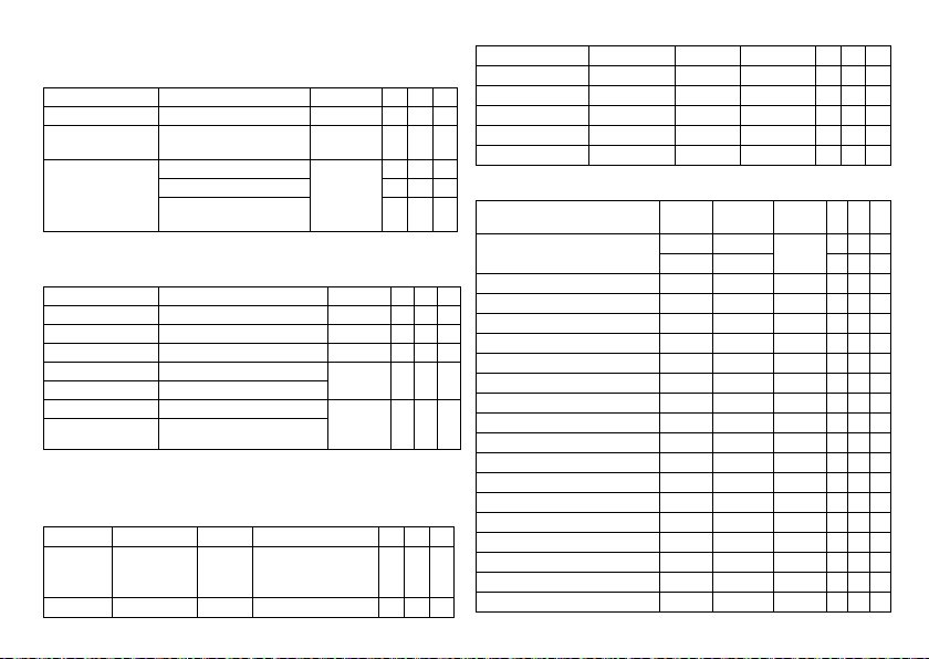
Preset Programs
Standard and safe program
Mode after auto-initialization:
Parameter Factory setting Standard Safe program SR DR HF
Mode VVI VVIR VVI
Mode DDD DDDR VVI x x
en • English
In the AAI mode, the safe
program is also AAI.
x
Lead configuration, determined and set immediately after connection (auto lead check):
Parameter Factory setting Standard Safe program SR DR HF
Pacing polarity A/RV Unipolar Unipolar Unipolar x x x
Pacing polarity LV TCUP TCUP — x
Sensing polarity A/RV Unipolar Unipolar Unipolar x x x
Sensing polarity LV Unipolar Unipolar — x
Automatic lead check ON ON — x x x
Parameters after auto-initialization:
x
Parameter Factory
Basic rate 60 bpm 60 bpm 70 bpm x x
Night rate OFF OFF OFF x x x
Rate hysteresis OFF OFF OFF x x x
Upper rate 130 bpm 130 bpm — x x
AV dynamics Low Low — x x
AV hysteresis mode OFF OFF — x x
Sense compensation -45 ms -45 ms — x x
AV safety delay 100 ms 100 ms — x x
x
VV delay 0 0 — x
LV T-wave protection ON ON — x
Far-field protection after Vs 100 ms 100 ms — x x
Far-field protection after Vp 150 ms 150 ms — x x
Ventricular blanking period after Ap 30 ms 30 ms — x x
PMT protection ON ON — x x
VA criterion 350 ms 350 ms — x x
Magnet response AUTO AUTO AUTO x x x
Pulse amplitude A 3.0 V 3.0 V — x x
Pulse amplitude RV 3.0 V 3.0 V 4.8 V x x x
Standard Safe
setting
50 bpm 50 bpm x
program
21
SR DR HF
Page 23

Parameter Factory
Pulse amplitude LV 3.0 V 3.0 V — x
Pulse width A 0.4 ms 0.4 ms — x x
Pulse width RV 0.4 ms 0.4 ms 1.0 ms x x x
Pulse width LV 0.4 ms 0.4 ms — x
Sensitivity A AUTO AUTO — x x
Sensitivity RV AUTO AUTO 2.5 mV x x x
Sensitivity LV AUTO AUTO — x
Refractory period A AUTO AUTO — x x
Refractory period RV 250 ms 250 ms 300 ms x x x
Refractory period LV 200 ms 200 ms — x
Mode switching ON ON — x x
Onset criterion 5-out-
Resolution criterion 5-out-
Intervention rate 160 bpm 160 bpm — x x
Switches to DDIR DDIR — x x
The basic rate with mode switching +10 bpm +10 bpm — x x
Rate stabilization with
mode switching
PVARP AUTO
PVARP after PVC 400 ms Automati-
Capture control A ON ON OFF x x x
Capture control RV ON ON OFF x x
Capture control LV ON ON OFF x
Atrial overdrive pacing OFF OFF — x x
Standard Safe
setting
5-out-of 8 — x x
of 8
5-out-of 8 — x x
of 8
OFF OFF — x x
225 ms — x x
(Start
250 ms)
cally set
SR DR HF
program
—xx
Parameter Factory
Vp suppression OFF OFF — x
IEGM recording (HAR) ON AT OFF x x x
IEGM recording (HVR) ON ON OFF x x x
Home Monitoring OFF OFF OFF xxx
setting
Standard Safe
program
SR DR HF
Tolerances of Parameter Values
Parameter Range of values Tolerance
Basic rate 30 ... (5) ... 100 ... (10)
Basic interval 1000 ms ± 20 ms
Magnet rate (magnet interval) 90 bpm (664 ms) ± 20 ms
Pulse amplitude 0.2 ... 7.5 V The greater value of ±50 mV
Pulse width 0.1 ... 1.5 ms The greater value of ±20 µs
Sensitivity A
EN 45502-2-1 triangle pulse
Sensitivity RV/LV
EN 45502-2-1 triangle pulse
Refractory period 200 ... 500 ms ± 20 ms
Maximum activity rate 80 ... 180 bpm ± 20 ms
Lead impedance 100 ... 200 Ω ±50 Ω
... 200 bpm
0.1 ... 0.2 mV The greater value of ±0.1 mV
0.3 ... 7.5 mV
0.5 ... 7.5 mV ±20%
201 ... 2500 Ω ±10%
± 20 ms
or +20/-25%
or ±10%
or ±20%
22
Page 24

5 Technical Data
Mechanical Characteristics
Measurements for the housing
Device W x H x D [mm]
Single-chamber SR(-T) 48 x 40 x 6.5 10 20.8
Dual-chamber DR(-T) 48 x 44 x 6.5 11 23.2
Triple-chamber HF-T 53 x 52 x 6.5 14 26.9
Triple-chamber HF-T QP 53 x 53 x 6.5 15 31.2
Note:
D = housing without header
X-ray identification
All device types receive the BIOTRONIK logo for X-ray identification. It can be found
centrally between the circuitry and the battery inside the housing and is visible on the
X-ray image.
Materials in contact with body tissue
•
Housing: Titanium
•
Header: Epoxy, polysulfone; IS4 seal: Silastic
•
Silicone plug: Silopren or silastic
Volume [cm3]
Mass [g]
Electrical Characteristics
Components and input values
Electrical characteristics determined at 37°C, 500 Ω:
Circuit technology Dycostrate
Input impedance > 10 kΩ
Pulse form Biphasic, asymmetric
Polarity Cathodic
Electrically conductive surface
The device housing has the form of a flattened ellipsoid. The electrically conductive
area is for:
•
Single and dual-chamber devices: 30 cm
•
Triple-chamber devices: 33 cm
Telemetry data
•
MICS frequency: 402 - 405 MHz
•
Maximum power of transmission: < 25 µW (-16 dBm)
International radio certification
Devices with BIOTRONIK Home Monitoring® are equipped with an antenna for wireless
communication.
•
Telemetry information for Australia:
This product is in compliance with the Australian "Radiocommuniations
Act 1992" and therefore it is labelled according to the "Radiocommunications
(Compliance Labelling - Devices) Notice."
•
Telemetry information for Japan:
In accordance with Japanese law, this device has been assigned an identification
number under the "Ordinance concerning certification of conformity with technical
regulations etc. of specified radio equipment", Article 2-1-8.
R 202-LSE015
2
2
en • English
23
Page 25
•
Telemetry information for the USA:
Telemetry data for the USA: This transmitter is authorized by rule under the
Medical Device Radiocommunication Service (in part 95 of the FCC Rules) and must
not cause harmful interference to stations operating in the 400.150-406.000 MHz
band in the Meteorological Aids (i.e., transmitters and receivers used to communicate weather data), the Meteorological Satellite, or the Earth Exploration Satellite
Services and must accept interference that may be caused by such stations,
including interference that may cause undesired operation. This transmitter shall
be used only in accordance with the FCC Rules governing the Medical Device Radiocommunication Service. Analog and digital voice communications are prohibited.
Although this transmitter has been approved by the Federal Communications
Commission, there is no guarantee that it will not receive interference or that any
particular transmission from this transmitter will be free from interference.
This device will be registered with Federal Communications Commission under the
following number:
FCC ID: QRIPNP
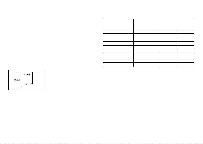
Pulse form
The pacing pulse has the following form:
The pulse amplitude reaches its maximum value
at the beginning of the pulse (Ua). With
increasing pacing duration (tb), the pulse
amplitude is reduced dependent on the pacing
impedance.
Resistance to interference
All variants of BIOTRONIK devices comply with the requirements of EN 45502-2-1:
2003, § 27.5.1 at the highest sensitivity.
Battery Data
Battery characteristics
The following data is provided by the manufacturers:
Manufacturer Wilson
Battery type GB 3193 LiS 2650MK LiS 3150MK
System
GREATBATCH, INC.
Clarence, NY 14031
®
QMR
Li-CFX/SVO
LITRONIK GmbH
01796 Pirna
Germany
LiMn0
2
LiMn0
Device type SR; DR SR; DR HF; HF QP
Battery voltage at BOS 3.3 V 3.1 V 3.1 V
Open-circuit voltage 3.3 V 3.1 V 3.1 V
Nominal capacity 1010 mAh 950 mAh 1200 mAh
Usable capacity until EOS 971 mAh 880 mAh 1066 mAh
Remaining capacity at ERI 39 mAh 70 mAh 134 mAh
Shortening of the service time after long storage period
In case of implantation after an average storage period – about 1 year before the end of
the use by date – the average service time decreases by about 1%.
Devices should be implanted within 19 months between the manufacturing date and the
use by date (indicated on the package).
Power consumption
•
BOS, inhibited: SR(-T), DR(-T) 6 µA; HF-T (QP) 7 µA
•
BOS, 100% pacing: SR(-T) 8 µA; DR(-T) 11 µA; HF-T (QP) 14 µA
Calculation of service times
Mean service times pre-estimated from the following and other data:
•
Storage for 6 months
•
Technical data of the battery manufacturer
•
Basic rate of 60 bpm in AAIR/VVI R modes (single-chamber devices) or DDDR mode s
(dual-chamber and triple-chamber devices)
•
Home Monitoring configuration: OFF
•
No wandless telemetry
•
Configuration of different pulse amplitudes and lead impedances
24
2
Page 26
Mean service times SR
For single-chamber devices the following times result when set to AAIR or VVIR, with
a basic rate of 60 bpm and a pulse width of 0.4 ms at an impedance of 500 Ω:
Amplitude Pacing Average service time
2.5 V 100% 13 years
3.0 V 100% 11 years, 3 months
5.0 V 100% 5 years, 6 months
Mean service times DR
For dual-chamber devices, the following times result when set to DDDR with a basic
rate of 60 bpm and a pulse width of 0.4 ms at an impedance of 500 Ω:
Amplitude Pacing Average service time
A: 2.5 V
RV: 2.5 V
A: 3.0 V
RV: 3.0 V
A: 5.0 V
RV: 5.0 V
50% 14 years, 9 months
50% 13 years, 7 months
100% 9 years, 4 months
50% 11 years, 4 months
100% 7 years, 8 months
50% 10 years
100% 3 years, 2 months
Mean service times HF
For triple-chamber devices of the 8 series, the following times result when set to DDDR
with a basic rate of 60 bpm, 100% biventricular pacing and a pulse width of 0.4 ms at an
impedance of 500 Ω:
Amplitude Pacing Average service time
A: 2.5 V 10% 9 years, 8 months
RV: 2.5 V
LV: 2.5 V
A: 3.0 V 10 % 8 years
RV: 3.0 V
LV: 3.0 V
A: 5.0 V
RV: 5.0 V
LV: 5.0 V
100%
100%
100% 2 years, 6 months
en • English
25
Page 27
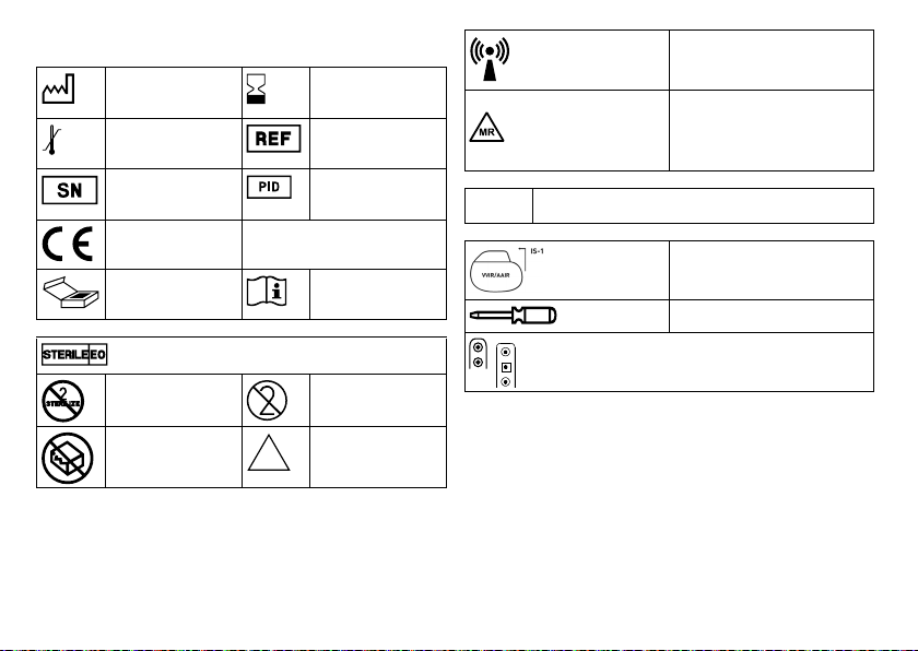
Legend for the Label
NON
STERILE
The label icons symbolize the following:
Manufacturing date Use by
Storage temperature Order number
Serial number Product identification
CE mark
Contents Follow the instructions for
number
use!
Label icon on devices with ProMRI®:
TP2
Compabiltiy with telemetry protocol version 2
of BIOTRONIK Home Monitoring
Example
Transmitter with non-ionizing radiation at
designated frequency
MR conditional: Patients having a device
system implanted whose components are
labeled with this symbol on the packaging
can be examined using an MR scan under
precisely defined conditions.
Uncoated device:
NBG code and compatible leads
Screwdriver
Sterilized with ethylene oxide
Do not resterilize Single use only,
Do not use if packaging is
damaged
do not reuse
Non-sterile
Examples of the connector allocation: IS-1, IS-1/IS4
26
Page 28

es • Español
Descripción del producto . . . . . . . . . . . . . . . . . . . . . . . . . . . . . . . . . . . . . . . . . . . . . . . . . 27
Uso médico indicado. . . . . . . . . . . . . . . . . . . . . . . . . . . . . . . . . . . . . . . . . . . . . . . 27
Indicaciones . . . . . . . . . . . . . . . . . . . . . . . . . . . . . . . . . . . . . . . . . . . . . . . . . . . . . 27
Contraindicaciones. . . . . . . . . . . . . . . . . . . . . . . . . . . . . . . . . . . . . . . . . . . . . . . . 28
Presentación del sistema. . . . . . . . . . . . . . . . . . . . . . . . . . . . . . . . . . . . . . . . . . . 29
Funciones diagnósticas y terapéuticas. . . . . . . . . . . . . . . . . . . . . . . . . . . . . . . . 32
Indicaciones generales de seguridad . . . . . . . . . . . . . . . . . . . . . . . . . . . . . . . . . . . . . . . 33
Condiciones de funcionamiento. . . . . . . . . . . . . . . . . . . . . . . . . . . . . . . . . . . . . . 33
Posibles complicaciones . . . . . . . . . . . . . . . . . . . . . . . . . . . . . . . . . . . . . . . . . . . 34
Posibles riesgos . . . . . . . . . . . . . . . . . . . . . . . . . . . . . . . . . . . . . . . . . . . . . . . . . . 34
Implantación . . . . . . . . . . . . . . . . . . . . . . . . . . . . . . . . . . . . . . . . . . . . . . . . . . . . . . . . . . . 36
Procedimiento de implantación. . . . . . . . . . . . . . . . . . . . . . . . . . . . . . . . . . . . . . 36
Medidas de precaución durante la programación . . . . . . . . . . . . . . . . . . . . . . . 38
Respuesta imán . . . . . . . . . . . . . . . . . . . . . . . . . . . . . . . . . . . . . . . . . . . . . . . . . . 40
Seguimiento . . . . . . . . . . . . . . . . . . . . . . . . . . . . . . . . . . . . . . . . . . . . . . . . . . . . . 40
Información para el paciente. . . . . . . . . . . . . . . . . . . . . . . . . . . . . . . . . . . . . . . . 41
Indicaciones de recambio . . . . . . . . . . . . . . . . . . . . . . . . . . . . . . . . . . . . . . . . . . 41
Explantación y sustitución del generador. . . . . . . . . . . . . . . . . . . . . . . . . . . . . . 43
Parámetros . . . . . . . . . . . . . . . . . . . . . . . . . . . . . . . . . . . . . . . . . . . . . . . . . . . . . . . . . . . . 43
Temporizado . . . . . . . . . . . . . . . . . . . . . . . . . . . . . . . . . . . . . . . . . . . . . . . . . . . . . 43
Estimulación y detección . . . . . . . . . . . . . . . . . . . . . . . . . . . . . . . . . . . . . . . . . . . 45
Adaptación de frecuencia . . . . . . . . . . . . . . . . . . . . . . . . . . . . . . . . . . . . . . . . . . 47
Programa RMN . . . . . . . . . . . . . . . . . . . . . . . . . . . . . . . . . . . . . . . . . . . . . . . . . . . 48
Programas preconfigurados . . . . . . . . . . . . . . . . . . . . . . . . . . . . . . . . . . . . . . . . 48
Tolerancias de los valores de los parámetros . . . . . . . . . . . . . . . . . . . . . . . . . . 50
Datos técnicos . . . . . . . . . . . . . . . . . . . . . . . . . . . . . . . . . . . . . . . . . . . . . . . . . . . . . . . . . . 50
Datos de referencia mecánicos . . . . . . . . . . . . . . . . . . . . . . . . . . . . . . . . . . . . . . 50
Características eléctricas . . . . . . . . . . . . . . . . . . . . . . . . . . . . . . . . . . . . . . . . . . 51
Información de la batería. . . . . . . . . . . . . . . . . . . . . . . . . . . . . . . . . . . . . . . . . . . 51
Leyenda de la etiqueta . . . . . . . . . . . . . . . . . . . . . . . . . . . . . . . . . . . . . . . . . . . . . 53
Índice
1 Descripción del producto
Uso médico indicado
Uso conforme a lo previsto
Evity es el nombre de una gama de marcapasos implantables que se pueden implantar
en caso de cualquiera de las indicaciones de arritmias bradicárdicas. El objetivo
primordial de la terapia es mejorar los síntomas del paciente de manifestación clínica.
La implantación del marcapasos supone una terapia sintomática con el objetivo
siguiente:
•
Compensación de bradicardias mediante la estimulación auricular, ventricular
o secuencial AV
•
Con generadores tricamerales también: Resincronización de la contracción
ventricular por estimulación biventricular
Formas de diagnóstico y de tratamiento
El ritmo cardiaco se supervisa automáticamente; las arritmias bradicárdicas son
tratadas. Esta familia de generadores reúne todos los modelos esenciales de terapia
cardiológica y electrofisiológica. BIOTRONIK Home Monitoring® permite a los médicos
gestionar la terapia las 24 horas del día.
Conocimientos técnicos requeridos
Aparte de los conocimientos médicos básicos, es necesario tener conocimientos
específicos acerca del funcionamiento y las condiciones de empleo de un sistema
generador.
•
Únicamente personal médico especializado con estos conocimientos específicos
está capacitado para emplear de forma adecuada el generador.
•
En caso de no poseer estos conocimientos los usuarios deben recibir formación
específica.
Indicaciones
Directrices de las sociedades cardiológicas
Las recomendaciones, indicaciones y métodos de diagnósticos diferenciales aprobados
generalmente para la terapia de marcapasos se aplican a los generadores de
BIOTRONIK.
es • Español
27
Page 29
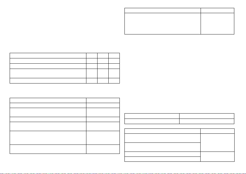
Todo ello se basa en las directrices de las asociaciones cardiológicas:
•
Recomendamos que se tengan en cuenta las indicaciones publicadas por la DGK
(Deutsche Gesellschaft für Kardiologie, Herz- und Kreislaufforschung) y la ESC
(European Society of Cardiology).
•
Recomendamos así que se tengan en cuenta la Heart Rhythm Society (HRS),
la American College of Cardiology (ACC), la American Heart Association (AHA) y
otras asociaciones de cardiología nacionales.
Tipos de generadores
Ante los siguientes síntomas o expectativas están indicados los tipos de generadores
que se indican a continuación:
Síntomas/expectativas SR DR HF
Desorientación causada por bradicardia x x x
Presíncope xxx
Beneficio de la resincronización del ventrículo derecho e
izquierdo
Síncope xxx
Modos de estimulación
Ante los siguientes síntomas están indicados los modos que se indican a continuación:
Síntomas/expectativas Modos de estimulación
Síndrome del nodo sinusal Estimulación bicameral
Bloqueo AV de segundo o tercer grado; crónico,
sintomático
Síndrome de Adams Stokes Estimulación bicameral
Bloqueo de rama bifascicular sintomático, siempre que la
taquiarritmia u otras causas estén descartadas
•
Incompetencia cronotrópica
•
Beneficio por un aumento de la frecuencia de
estimulación al realizar una actividad física
Disfunción del nodo sinusal con conducción intraventricular y AV intacta
Estimulación bicameral
Estimulación bicameral
Modo R o CLS
Estimulación auricular
Síntomas/expectativas Modos de estimulación
Bradicardia en combinación con:
•
Ritmo sinusal normal con solo episodios raros de
bloqueo AV o anomalías del nodo sinusal
•
Fibrilación auricular crónica
•
Discapacidad física grave
Compatibilidad condicionada con RMN (MR conditional)
Los marcapasos MR conditional marcados con ProMRI® pueden emplearse sin riesgo
en entornos condicionados de RMN, siempre que se utilicen junto con un sistema
implantable MR conditional completo y de acuerdo a las instrucciones proporcionadas
en el manual ProMRI.
Contraindicaciones
Pautas fundamentales
x
No se conocen contraindicaciones para la implantación de marcapasos multifuncionales monocamerales, bicamerales o tricamerales. Debe existir siempre un diagnóstico diferencial previo para la implantación de acuerdo con las directrices aplicables.
No se configurarán los modos ni las combinaciones de parámetros que puedan poner
en peligro al paciente.
Modos y parámetros
Se debe comprobar que las combinaciones de parámetros sean efectivas y compatibles. Después de la programación también deben controlarse y, en caso necesario,
adaptarse.
Condiciones Modo contraindicado
DAI adicional implantado Estimulación unipolar
Condiciones Modo inadecuado
Taquicardias auriculares crónicas, fibrilación auricular
crónica o flúter
Mala tolerancia a frecuencias de estimulación por encima
de la frecuencia básica, por ejemplo, angina de pecho
Trastorno de conducción AV Estimulación monocaDisminución de conducción AV
28
Estimulación ventricular
Modos con control
auricular (DDD, VDD, AAI)
meral en aurícula
Page 30

Condiciones Adaptación de parámetros
Conducción retrógrada lenta tras estimulación ventricular: Riesgo de taquicardias
mediadas por el marcapasos
Mala tolerancia a frecuencias de estimulación por encima de la frecuencia básica,
por ejemplo, angina de pecho
•
Prolongar el periodo refractario
auricular
o bien:
•
Reducir el retardo AV
•
Más raramente:
Programar DDI, DVI o VVI
•
Reducir la frecuencia superior
•
Reducir la frecuencia máxima del
sensor
•
Aplicar sobreestimulación auricular
Presentación del sistema
Familia de generadores
Esta familia de generadores está compuesta por generadores mono, bi y tricamerales
con o sin Home Monitoring. No todos los tipos de generadores se encuentran disponibles en todos los países.
Existen las variantes de generador siguientes:
Tipo de
generador
Monocameral Evity 6 SR-T, Evity 8 SR-T —
Bicameral Evity 6 DR-T, Evity 8 DR-T —
Tricameral Evity 8 HF-T, Evity 8 HF-T QP —
Generador
La carcasa del generador es de titanio biocompatible, está soldada por fuera, de modo
que queda sellada herméticamente. La forma elipsoidal facilita el encapsulamiento en
la zona de los músculos pectorales. La carcasa actúa como polo opuesto en caso de
configuración unipolar de los electrodos.
Conexiónes de los electrodos
BIOTRONIK ofrece marcapasos con bloques conectores para distintos puertos
estandarizados.
•
IS-1
•
IS-1/IS4
es • Español
Variantes con
Home Monitoring
Variantes sin
Home Monitoring
Nota:
Los electrodos adecuados deben ser acordes con las normas:
•
Al puerto IS-1 de un generador solo se le pueden conectar electrodos que
cumplan la norma ISO 5841-3 y que incorporen un conector de electrodo IS-1.
•
Al puerto IS4 de un generador solo se le pueden conectar electrodos que cumplan
la norma ISO 27186 y que incorporen un conector de electrodo IS4.
Nota:
El generador y los electrodos deben ser compatibles.
•
Al tipo de generador HF QP con IS4 solo se le pueden conectar electrodos tetrapolares a los puertos de los conectores IS4.
Nota:
Para conectar electrodos con otro tipo de conexiones utilice solo los adapta-
dores autorizados por BIOTRONIK.
•
Diríjase a BIOTRONIK para aclarar cualquier duda acerca de la compatibilidad con
electrodos de otros fabricantes.
IS-1
La inscripción del generador aporta información sobre la disposición de las
conexiones:
SR DR HF
Puerto Conector de
electrodo
A/AD IS-1 Unipolar, bipolar Aurícula DR, HF
V/VD IS-1 Unipolar, bipolar Ventrículo derecho SR, DR, HF
LV IS-1 Unipolar, bipolar Ventrículo izquierdo HF
Configuración Lugar de
implantación
29
Tipo de
generador
Page 31

IS-1/IS4
La inscripción del generador aporta información sobre la disposición de las
conexiones:
HF QP
Puerto Conector de
electrodo
AD IS-1 Unipolar, bipolar Aurícula HF QP
VD IS-1 Unipolar, bipolar Ventrículo derecho HF QP
LV IS4 Unipolar, bipolar Ventrículo izquierdo HF QP
Electrodos
Los electrodos de BIOTRONIK están recubiertos de silicona biocompatible. Permiten
maniobrar con flexibilidad, ofrecen estabilidad a largo plazo y están equipados para la
fijación activa o pasiva. Se implantan con ayuda de un introductor. Algunos electrodos
están recubiertos de poliuretano para un mejor deslizamiento. Los electrodos con
esteroides reducen los procesos inflamatorios. El modelo fractal de electrodos proporciona umbrales de estimulación bajos, impedancias de estimulación elevadas y un
riesgo de sobredetección mínima.
BIOTRONIK ofrece adaptadores para poder conectar electrodos ya implantados
a nuevos generadores.
Telemetría
La comunicación telemétrica entre el generador y el programador puede establecerse
tras la inicialización bien mediante la aplicación de un cabezal de programación (PGH)
o bien mediante la telemetría sin cabezal inalámbrica (telemetría de alta frecuencia).
Configuración Lugar de
implantación
Tipo de
generador
30
Programador
El programador permite medir los umbrales de estimulación y efectuar otras pruebas,
tanto durante la implantación, como durante los seguimientos presenciales. El programador permite además consultar la configuración del modo y de las combinaciones de
parámetros, así como interrogar y guardar los datos del generador. En la pantalla en
color pueden visualizarse simultáneamente ECG inalámbrico, EGMI, marcadores y
funciones.
Modos
La configuración del modo depende del diagnóstico concreto:
Tipo de generador Modos Estándar
SR
DR
HF (QP) (serie 8)•VVI-CLS; DDD-CLS
Nota:
Home Monitoring es posible en todos los modos.
El modo OFF solo funciona temporalmente, por ejemplo, durante una prueba.
•
VVI-CLS (solo con la serie 8)
•
VVIR, V00R, AAIR, A00R
•
VVI, VVT, V00, AAI, AAT, A00
•
OFF
•
VVI-CLS; DDD-CLS (solo con la serie 8)
•
DDD-ADI, DDDR-ADIR (series 6 y 8)
•
DDDR, DDIR, DVIR, D00R, VDDR, VDIR
•
VVIR, V00R, AAIR, A00R
•
DDD, DDT, DDI, DVI, D00, VDD, VDI
•
VVI, VVT, V00, AAI, AAT, A00
•
OFF
•
DDD-ADI, DDDR-ADIR
•
DDDR, DDIR, DVIR, D00R, VDDR, VDIR
•
VVIR, V00R, AAIR, A00R
•
DDD, DDT, DDI, DVI, D00, VDD, VDI
•
VVI, VVT, V00, AAI, AAT, A00
•
OFF
VVIR
DDDR
DDDR
Page 32

Códigos NBG
AAIR o VDDR es el código NBG para el modo antibradicardia de los generadores monocamerales:
A/V Estimulación en la aurícula o en el ventrículo
A/V Detección en la aurícula o en el ventrículo
I Inhibición de impulsos en la aurícula y el ventrículo
R Adaptación de frecuencia
DDDR es el código NBG para el modo antibradicardia de los generadores bicamerales:
D Estimulación en la aurícula y el ventrículo
D Detección en la aurícula y el ventrículo
D Inhibición y disparo del impulso
R Adaptación de frecuencia
DDDRV es el código NBG para el modo antibradicardia de los generadores tricamerales:
D Estimulación en la aurícula y el ventrículo
D Detección en la aurícula y el ventrículo
D Inhibición y disparo del impulso
R Adaptación de frecuencia
V Estimulación multisitio en ambos ventrículos
BIOTRONIK Home Monitoring
Aparte del tratamiento efectivo de estimulación, BIOTRONIK ofrece una gestión
integral de la terapia.
•
Con Home Monitoring se transmiten datos diagnósticos y terapéuticos y datos
técnicos del generador a un transmisor móvil o estacionario de forma automática e
inalámbrica por medio de una antena situada en el bloque de conexión del generador. El transmisor codifica los datos y los envía al BIOTRONIK Service Center
a través de la red de telefonía móvil.
®
•
Los datos recibidos se descodifican y se evalúan. Cada médico puede config urar los
criterios de evaluación de forma personalizada para cada pa ciente y decidir cuándo
desea ser informado por fax, SMS o correo electrónico.
•
Los resultados de esta evaluación se ponen a disposición de los médicos encargados del tratamiento de forma resumida en la plataforma segura de Internet
denominada Home Monitoring Service Center (HMSC).
•
La transmisión de datos desde el generador se realiza junto con el mensaje diario.
•
Los mensajes del generador que indican eventos especiales del corazón del
paciente o del generador se transmiten con el siguiente mensaje regular.
•
Los mensajes de prueba pueden iniciarse en cualquier momento desde el programador para controlar la función Home Monitoring de forma inmediata.
Números de referencia de Evity
Los generadores se pueden adquirir como sigue:
Evity 6 SR-T 407161 Evity 8 DR-T 407146
Evity 6 DR-T 407149 Evity 8 HF-T 407140
Evity 8 SR-T 407158 Evity 8 HF-T QP 407139
Posibilidades de suministro
En el envase de almacenamiento se encuentra lo siguiente:
•
Envase estéril con generador
•
Etiqueta con el número de serie
•
Tarjeta de identificación del paciente
•
Documento de garantía
Nota:
El manual técnico del generador se suministra impreso en el envase de alma-
cenamiento y también se encuentra disponible en formato digital en Internet.
En el envase estéril se encuentra lo siguiente:
•
Generador
•
Destornillador
es • Español
31
Page 33

Funciones diagnósticas y terapéuticas
Resumen general
Todos los sistemas disponen de numerosas funciones para el diagnóstico rápido y el
tratamiento seguro de las bradicardias.
•
Las funciones automáticas permiten implantar, configurar y controlar el marcapasos sin problemas y en poco tiempo.
•
Inicialización automática tras la implantación: el generador detecta los electrodos
implantados de forma automática y configura la polaridad. Las funciones automáticas del software se activan al cabo de 10 min.
Funciones diagnósticas
•
Los datos de los últimos seguimientos y consultas se registran junto con los
episodios de arritmia; se guardan junto con otros datos con el fin de poder evaluar
en todo momento el estado del paciente y el del generador.
•
Para controlar el funcionamiento de los electrodos se mide la impedancia en el
generador de forma automática, continua y por debajo del umbral, tanto si hay un
impulso de estimulación como si no.
•
En los seguimientos presenciales, el EGMI se indica con marcadores, una vez
establecida una conexión telemétrica durante el proceso de prueba con el programador.
Estimulación antibradicardia
•
Detección: las amplitudes de las ondas P y R se miden en el generador permanentemente y de forma totalmente automática para registrar también los cambios de
amplitud. La sensibilidad auricular y ventricular también se adapta de forma
continua y totalmente automática. Se calcula la media de los datos de medida y se
puede mostrar la tendencia.
•
Umbrales de estimulación: Los umbrales de estimulación se determinan automáticamente en el generador; los generadores monocamerales determinan los
umbrales de estimulación del ventrículo derecho; los generadores bicamerales,
los de la aurícula y el ventrículo derecho; los generadores tricamerales, los de la
aurícula y el ventrículo izquierdo y derecho. El control de captura permite ajustar
las amplitudes de impulso de modo que, cada vez que se modifique el umbral de
estimulación, se estimule con la amplitud óptima para el paciente.
•
Temporizado: a fin de evitar taquicardias mediadas por el marcapasos, en generadores bi y tricamerales la estimulación auricular se controla en especial mediante
la adaptación automática del periodo refractario auricular (función PRAPV automática: periodo refractario auricular postventricular automático).
•
Forma especial y adicional de la adaptación de frecuencia en generadores de la
serie 8: una mayor demanda cardiaca se detecta mediante la medición fisiológica
de la impedancia. El principio de medición se basa en la contractilidad (inotropía)
modificada del miocardio (función CLS: estimulación de ciclo cerrado). En el modo
CLS, la adaptación de la frecuencia se inicializa y se optimiza automáticamente.
•
Supresión de estimulación ventricular: Cuando la estimulación ventricular no es
necesaria, se puede evitar favoreciendo la conducción intrínseca (función supresión vp). Durante este proceso, se puede adaptar el generador a los cambios de la
conducción. En caso de conducción AV intrínseca el generador pasa de un modo
DDD(R) a un modo ADI(R).
•
Serie 8: Para mejorar el rendimiento cardiaco, durante el seguimiento presencial
se efectúa una prueba automática de retardo AV. Se calcularán retardos AV;
pueden adoptarse los valores óptimos.
Terapia de resincronización
Para resincronizar los ventrículos, los generadores tricamerales disponen de
funciones para configurar diversos retardos VV.
•
También se dispone del control de captura automático para el ventrículo izquierdo
con seguimiento automático del umbral de estimulación o monitorización automática del umbral de estimulación (ATM) con el objetivo de obtener análisis de
tendencias.
•
Para evitar tener que volver a operar en caso de que aumente el umbral de estimulación en el lado izquierdo o de que se produzca una estimulación indeseada del
nervio frénico, en un generador tricameral pueden configurarse polaridades de
estimulación distintas para el electrodo del ventrículo izquierdo; con el tipo de
generador HF QP, hasta 13 vectores.
•
Serie 8: En el caso del generador QP, la prueba del vector VI ofrece una medida
rápida del umbral de estimulación, del umbral de estimulación del nervio frénico y
de la impedancia de estimulación. Además se indica la influencia relativa en el
tiempo de servicio. Los resultados de medida se evalúan automáticamente, para
que se pueda configurar la polaridad de estimulación óptima.
Además, la breve prueba de conducción VD-VI apoya esta selección.
•
Función diagnóstica adicional en caso de estimulación biventricular: la variabilidad
de la frecuencia cardiaca, la actividad del paciente y la impedancia torácica se
monitorizan continuamente.
32
Page 34

Programas
Existen dos tipos de programas de terapia:
•
Los parámetros preconfigurados están disponibles para las indicaciones más
frecuentes (función Program Consult).
•
Los ajustes individuales pueden guardarse en tres programas de terapia distintos.
Los generadores con ProMRI detectan los equipos de RMN
El sensor permite detectar de manera fiable el campo magnético estático de un equipo
de RMN. Este sensor puede activarse durante una interrogación mediante la función
MRI AutoDetect un máximo de 14 días.
Si durante el periodo ajustado el paciente se acerca a un equipo de RMN, el generador
detecta su campo magnético estático y activa automáticamente el programa RMN
preconfigurado. Una vez se aleje del tomógrafo, se restablecerá de manera automática
el programa permanente.
Funciones de Home Monitoring
El generador envía información al transmisor una vez al día de forma automática.
Asimismo, es posible generar mensajes prueba con ayuda del programador. Algunos
de los datos médicos importantes son:
•
Arritmias auriculares y ventriculares sostenidas
•
Parámetros relevantes para los electrodos de la aurícula y el ventrículo: umbrales
de estimulación, amplitudes de detección, impedancias
•
Estadísticas actuales de la terapia antibradicardia
•
Intervalo de tiempo configurable por separado para los mensajes del generador
que amplían el mensaje habitual con información adicional
•
IEGM-Online HD® con un máximo de 3 canales en alta resolución (High Definition)
•
Transmisión de los registros EGMI con los mensajes del generador
2 Indicaciones generales de seguridad
W
ATENCIÓN
Información de seguridad
La electroterapia en el corazón implica condiciones de funcionamiento especiales, así
como posibles complicaciones y riesgos.
•
Observe atentamente toda la información de seguridad.
Condiciones de funcionamiento
Manuales técnicos
Los siguientes manuales técnicos informan sobre el uso de sistemas implantables:
— Manual técnico del generador
— Manual técnico del HMSC
— Manuales técnicos de los electrodos
— Manual técnico del programador y sus accesorios
— Manuales técnicos de la interfaz de usuario
— Manuales técnicos de cables, adaptadores y accesorios
•
Los manuales técnicos bien se suministran en el envase de almacenamiento,
o bien están disponibles en formato digital en Internet.
manuals.biotronik.com
•
Observe las instrucciones de todos los manuales técnicos pertinentes.
•
Conserve los manuales técnicos para poder consultarlos en el futuro.
Tratamiento durante el transporte y el almacenamiento
•
Los generadores no se deben almacenar cerca de imanes ni de fuentes de interferencia electromagnética.
•
Tenga en cuenta los efectos derivados del tiempo de almacenamiento, véase la
información de la batería.
Temperatura
Las temperaturas extremas, ya sean demasiado altas o demasiado bajas, repercuten
en el tiempo de servicio de la batería colocada en el generador.
•
Para el transporte y el almacenamiento se permite:
de -10 ºC a +45 ºC
Suministro estéril
El generador y el destornillador se suministran esterilizados con gas. La esterilidad
solo se garantiza si el contenedor de plástico y el sellado de control de calidad no están
dañados.
Envase estéril
El generador y el destornillador están envasados por separado en dos contenedores de
plástico sellados: El contenedor de plástico interior también es estéril por fuera para
que en la implantación se pueda entregar estéril.
es • Español
33
Page 35

Un solo uso
El generador y el destornillador están diseñados para un solo uso.
•
No utilice el generador si el envase está dañado.
•
No está permitido reesterilizar ni reutilizar el generador.
Posibles complicaciones
Generalidades sobre complicaciones médicas
En general, con los generadores de BIOTRONIK pueden darse las complicaciones
habituales en la consulta médica, y que afectan tanto a pacientes como a los sistemas
de implantación.
•
Entre las complicaciones se incluyen, por ejemplo, acumulación de líquido en la
bolsa de implantación, infecciones o reacciones tisulares, determinadas a partir
del estado actual de la ciencia y la técnica.
•
Es imposible garantizar la fiabilidad de la terapia antiarrítmica, ni siquiera en los
casos en los que los programas han resultado eficaces durante las pruebas o los
exámenes electrofisiológicos posteriores. En raras circunstancias, los parámetros
configurados pueden ser ineficaces. En especial, no puede descartarse que se
induzcan taquiarritmias.
Miopotenciales esqueléticos
El generador adapta la detección bipolar y el control de la sensibilidad de tal manera al
ámbito de frecuencias del ritmo espontáneo que los miopotenciales esqueléticos
normalmente no se llegan a detectar. No obstante, sobre todo en caso de configuración
unipolar y/o de sensibilidad muy elevada, pueden clasificarse los miopotenciales
esqueléticos como ritmos espontáneos y, según la interferencia, provocarse una inhibición o una terapia antiarrítmica.
Estimulación nerviosa y muscular
Un sistema generador compuesto por electrodos unipolares y un generador sin recubrimiento puede provocar una estimulación no deseada del diafragma si la amplitud de
impulso configurada es alta al principio o constantemente.
Posibles fallos técnicos
En principio, no es posible excluir fallos técnicos en un sistema implantable. Las
causas pueden ser, entre otras, las siguientes:
•
Dislocación del electrodo
•
Fractura del electrodo
•
Defectos del aislamiento
•
Fallo de los componentes del generador
•
Agotamiento de la batería
Interferencia electromagnética (IEM)
Cualquier generador puede recibir interferencias, por ejemplo, si se detectan señales
externas como si fueran ritmo intrínseco:
•
En el diseño de los generadores BIOTRONIK se ha minimizado la influencia que las
IEM puedan ejercer sobre ellos.
•
La gran variedad de tipos e intensidades de IEM hace imposible garantizar una
seguridad absoluta. En el caso improbable de que las IEM llegaran a provocar
algún síntoma en el paciente, puede presuponerse que serán insignificantes.
•
Según el modo de estimulación y el tipo de interferencia, estas fuentes de interferencias pueden provocar la inhibición o el disparo del impulso, o bien el aumento
de la frecuencia de estimulación dependiente del sensor, o bien una estimulación
asíncrona.
•
En circunstancias desfavorables, y en particular durante la aplicación de medidas
terapéuticas y de diagnóstico, las fuentes de interferencias pueden dar lugar a una
energía tan elevada que llegue a dañar el tejido que rodea el generador o la punta
del electrodo.
Comportamiento del generador en caso de IEM
En caso de interferencias electromagnéticas o miopotenciales indeseados, el
generador estimula de manera asíncrona durante todo el periodo en el que se
sobrepase la frecuencia de interferencia.
Campos magnéticos estáticos
El marcapasos conmuta a la respuesta imán a partir de una potencia de campo
> 1,0 mT.
Posibles riesgos
Procedimientos que deben evitarse
A causa de posibles daños para el paciente o el generador y de la inseguridad que ello
comporta en su funcionamiento, los procedimientos siguientes deben evitarse:
•
Ultrasonidos terapéuticos
•
Estimulación nerviosa eléctrica transcutánea
•
Tratamiento con oxígeno hiperbárico
•
Cargas de presión por encima de la presión normal
34
Page 36

Procedimientos terapéuticos y diagnósticos arriesgados
En caso de que se derive una corriente eléctrica desde una fuente externa al cuerpo
con fines diagnósticos o terapéuticos, el generador se puede averiar, y la vida del
paciente podría correr peligro.
Si se emplea un procedimiento de termoterapia de alta frecuencia, p. ej., electrocauterización, ablación de alta frecuencia o cirugía de alta frecuencia, se pueden llegar
a inducir arritmias o fibrilación ventricular. En el caso, p. ej., de litotricia se puede
llegar a generar un efecto de presión nociva. En ocasiones, los efectos en el generador
no pueden apreciarse de forma inmediata.
En caso de no poder evitar los procedimientos arriesgados, siempre deben aplicarse
los puntos siguientes:
•
Aislamiento eléctrico del paciente.
•
En caso necesario, cambie el funcionamiento del marcapasos a los modos asíncronos.
•
No genere fuentes de energía en las inmediaciones del sistema implantable.
•
Controle además el pulso periférico del paciente.
•
El paciente debe estar bajo supervisión durante y después de cada intervención.
Desfibrilación externa
El generador está protegido contra la energía que normalmente induce una desfibrilación externa. Sin embargo, cualquier generador puede verse dañado por una desfibrilación externa. Por medio de las corrientes inducidas sobre los electrodos implantados
se puede formar tejido necrótico alrededor de la punta de los electrodos. En consecuencia, las características de detección y los umbrales de estimulación pueden
cambiar.
•
Coloque los electrodos adhesivos en posición antero-posterior
o perpendicularmente al eje formado entre el generador y el corazón, así como
a una distancia mínima de 10 cm del generador y de los electrodos implantados.
Radioterapia
A causa de posibles daños en el generador y de la inseguridad que ello comporta en su
funcionamiento, el empleo de radioterapia terapéutica debe evitarse. En caso de que
sea necesario aplicar este tipo de terapia resulta de crucial importancia realizar una
valoración de utilidad y riesgo previa. La complejidad de todos los factores influyentes
(por ejemplo, las distintas fuentes de radiación, la gran variedad de generadores o las
condiciones terapéuticas) no permite establecer unas directivas que garanticen una
radioterapia sin efectos sobre el generador. La norma EN 45502 relativa a productos
sanitarios implantables activos exige en relación con la radiación ionizante las medidas
siguientes:
•
Deben tenerse en cuenta los procedimientos terapéuticos y diagnósticos arriesgados.
•
Apantalle el generador contra la radiación.
•
Después de aplicar la radiación, compruebe de nuevo que el sistema del generador
funciona correctamente.
Nota:
Si tiene cualquier duda acerca de la valoración de utilidad y riesgo, diríjase
a BIOTRONIK.
Imagen por resonancia magnética
La imagen por resonancia magnética (RMN) debe evitarse por las densidades de flujo
magnético y los campos de alta frecuencia asociados: daño o destrucción del sistema
implantable por fuerte interacción magnética y perjuicios para el paciente por calentamiento excesivo de los tejidos en la región del sistema implantable.
Bajo determinadas circunstancias, siempre y cuando se mantengan las medidas prescritas de protección del paciente y del sistema del generador, es posible realizar una
imagen por resonancia magnética. En BIOTRONIK los generadores con la función
"MR conditional" incluyen la identificación ProMRI.
•
El manual ProMRI® (Sistemas implantables MR conditional) contiene información
detallada sobre cómo llevar a cabo una RMN de forma segura.
—
Descarga del manual desde la página web:
manuals.biotronik.com
—
Solicite el manual impreso a BIOTRONIK.
•
¿La homologación de "MR conditional" tiene validez en su país o región?
Solicite información actual al respecto a BIOTRONIK.
es • Español
35
Page 37

3 Implantación
Procedimiento de implantación
Preparación de los componentes
Conforme a la Directiva de la CE 90/385/CEE se precisan los componentes descritos
a continuación:
•
Generador con destornillador de BIOTRONIK
•
Electrodos de BIOTRONIK e introductor:
—
Generador monocameral: un electrodo unipolar o bipolar para el ventrículo
derecho
—
Generador bicameral: uno por cada electrodo unipolar o bipolar para la
aurícula y el ventrículo derecho
—
Generador tricameral: adicionalmente un electrodo VI unipolar, bipolar
o tetrapolar
•
Las conexiones permitidas son IS-1 e IS4: Para conectar los electrodos con otras
conexiones o conectar electrodos de otros fabricantes utilice solo los adaptadores
autorizados por BIOTRONIK.
•
Programador de BIOTRONIK (con telemetría sin cabezal integrada o con un módulo
SafeSync aparte) y cable autorizado
•
Dispositivo externo de ECG multicanal
•
Tenga siempre preparados componentes estériles de reserva.
Tenga preparado un desfibrilador externo.
A fin de poder reaccionar ante emergencias imprevistas o posibles fallos del generador:
•
Tenga preparado un desfibrilador externo y palas o electrodos adhesivos.
Desembalaje del generador
W
ADVERTENCIA
Terapia inadecuada debido a daños en el generador
Si el generador, una vez desembalado, se cae durante la manipulación y choca contra
una superficie dura, los componentes electrónicos pueden quedar dañados.
•
Utilice un generador de recambio.
•
Envíe el generador averiado a BIOTRONIK.
•
Retire el papel de sellado del contenedor de plástico externo por el lugar marcado
en el sentido de la flecha. El contenedor de plástico interior no debe entrar en
contacto con personas ni con instrumentos que no estén esterilizados.
•
Sujete el contenedor de plástico interior por la lengüeta y extráigalo del contenedor
de plástico exterior.
•
Retire el papel de sellado del contenedor de plástico interno estéril por el lugar
marcado en el sentido de la flecha.
Nota:
El generador se entrega desactivado y se puede implantar en cuanto se
desembala sin tener que activarlo manualmente.
Comprobación de los componentes
Los daños en uno de los componentes pueden conllevar complicaciones o fallos.
•
Antes y después del desembalaje compruebe si los componentes presentan daños.
•
Cambie los componentes dañados.
Ubicación
Normalmente el marcapasos se implanta por vía subcutánea o subpectoral teniendo en
cuenta la configuración de los electrodos y la anatomía del paciente.
Resumen: Implantación
1 Modele la bolsa de implantación y prepare la vena.
2 Introduzca los electrodos y efectúe las medidas.
3 Conecte el generador y los electrodos.
4 Introduzca el generador.
El generador inicia por sí solo la inicialización automática.
5 Introduzca la seda de fijación por el orificio del bloque de conexión y fije el
generador en la bolsa ya preparada.
6 Cierre la bolsa de implantación.
7 Antes de realizar pruebas o de configurarlo, espere a que finalice la inicializa-
ción automática del generador.
Nota:
Si fuera necesario, el generador se puede programar también antes de la inicia-
lización automática o durante esta.
36
Page 38

Prevención de daños en el bloque conector
Los tornillos de conexión se deben enroscar o desenroscar con cuidado.
•
Afloje los tornillos de conexión con el destornillador suministrado. Emplee únicamente el destornillador con límite de torsión de BIOTRONIK.
•
Si fuera necesario revisar los electrodos, pida a BIOTRONIK un destornillador
estéril.
Prevención de cortocircuitos en el bloque conector
W
ADVERTENCIA
Cortocircuito a causa de puertos abiertos
Los puertos del bloque conector que se encuentren abiertos y con ello carezcan de
hermeticidad contra electrolitos pueden generar corrientes eléctricas indeseadas
hacia el cuerpo y la entrada de fluidos corporales en el generador.
•
Cierre los puertos no utilizados con conectores ciegos.
Guardar la distancia entre los electrodos
W
ADVERTENCIA
Terapia insuficiente
Si los electrodos no están separados por una distancia adecuada o están mal
colocados puede producirse una detección de campo lejano.
•
Los electrodos no deben tocarse. Coloque los polos proximales y distales de los
nuevos electrodos implantados a suficiente distancia de los electrodos antiguos.
Conexión del conector de electrodo al generador
1 Retire los estiletes y sus introductores.
2•Conecte el conector unipolar o bipolar IS-1 del ventrículo derecho al
puerto RV.
•
Conecte el conector unipolar o bipolar IS-1 de la aurícula al puerto A.
•
Conecte el conector unipolar o bipolar IS-1 o el tetrapolar IS4 del ventrículo
izquierdo al puerto LV.
3 Introduzca el conector del electrodo (sin doblar el conductor) en el bloque de
conexión hasta que se pueda ver la punta del conector por detrás del bloque de
tornillo.
4 Si el conector no se puede insertar por completo puede deberse a que el tornillo
de conexión sobresale del orificio del bloque de tornillo. Afloje con cuidado el
tornillo de conexión sin desenroscarlo del todo para evitar que entre ladeado al
enroscarlo.
5 Utilice el destornillador para atravesar el centro del tapón de silicona vertical-
mente por el punto de corte hasta llegar al tornillo de conexión.
6 Gire el tornillo de conexión en el sentido de las agujas del reloj hasta que se
aplique el límite de torsión (chasquido).
7 A continuación saque el destornillador con cuidado de no desenroscar el tornillo
de conexión.
•
Al retirar el destornillador, el tapón de silicona sellará por sí solo la
conexión del electrodo.
Colocación del cabezal de programación
En el cabezal de programación (PGH) se encuentra un croquis del generador. Este se
usa como indicador de posición en el momento de colocar el cabezal y garantiza una
telemetría correcta.
•
Procure posicionar correctamente el PGH.
Cómo establecer la telemetría RF
El programador debe encontrarse como mínimo a 20 cm y como máximo a 3 m del
generador; es preferible que no haya obstáculos entre el paciente y el programador.
•
Conecte la telemetría sin cabezal desde el programador.
•
Coloque el cabezal de programación duranto unos 2 s hasta que el programador
muestre una inicialización correcta:
El navegador muestra el símbolo de telemetría sin cabezal y la barra de
estado indica la intensidad de la señal.
•
Retire el cabezal de programación.
es • Español
37
Page 39

Inicialización automática
Cuando se detecte el primer electrodo conectado, la autoinicialización empieza de
forma automática.
En general, 10 min tras la conexión del primer electrodo, la inicialización automática
finaliza. Si durante este tiempo no se ha transmitido ningún programa más, el
generador funciona con las funciones automáticas activas en el programa de fábrica
o en el programa preajustado por el usuario.
No hace falta configurar manualmente la polaridad de los electrodos ni medir las
impedancias de los electrodos.
Nota:
Después de la inicialización automática, todos los parámetros están activados
como en el programa estándar.
Comportamiento durante la inicialización automática
•
Si se transmite un programa permanente:
Se concluye la inicialización automática, y el programa transmitido pasa a estar
activo.
•
Realización de pruebas:
Las pruebas no pueden realizarse durante la inicialización automática, por lo que
es preciso cancelarla. La inicialización automática no continúa a continuación.
Medidas de precaución durante la programación
W
ATENCIÓN
Información de seguridad
La programación de sistemas implantables requiere medidas de precaución especiales.
•
Observe atentamente todas la medidas de precaución.
Comprobación del sistema implantable
•
Después de la inicialización automática, realice un seguimiento para comprobar
que el sistema implantable funciona correctamente.
•
Realice una prueba del umbral de estimulación para establecerlo.
Realización de pruebas estándar y monitorización de pacientes
Durante las pruebas estándar el paciente también puede entrar en un estado crítico,
por ejemplo, por haber configurado los parámetros de forma inadecuada o debido a un
fallo de telemetría.
•
Por este motivo, el paciente también debe recibir una atención suficiente durante
las pruebas.
•
Una vez efectuada la prueba del umbral de estimulación, compruebe si el umbral
es representativo desde un punto de vista clínico y técnico.
•
Supervise continuamente el ECG y el estado del paciente.
•
En caso necesario, cancele la prueba.
No interrumpa la telemetría sin cabezal durante un tratamiento
Desconectar el módulo SafeSync del programador puede ser causa de interferencias
o interrupciones en la telemetría RF SafeSync.
•
No desconecte el módulo SafeSync del programador.
•
No extraiga el Operation Module del ICS 3000.
Cancelación de la telemetría
Los fallos de telemetría o del programador que surjan durante la ejecución de
programas temporales (pruebas de seguimiento) pueden conllevar una estimulación
inadecuada del paciente. Tal es el caso, si el programador no se puede manejar debido
a un fallo del programa o a un defecto de la pantalla táctil y, por consiguiente, resulta
imposible concluir el programa temporal. Ante esta situación, la solución consiste en
cancelar la telemetría, de modo que el generador se conmute automáticamente al
programa permanente.
•
En caso de telemetría con PGH: levante el cabezal de programación, como mínimo,
30 cm.
•
En caso de telemetría de RF: desconecte y recoloque el programador.
•
Desconecte las posibles fuentes de interferencias.
Cómo evitar las configuraciones de parámetros críticas
No pueden ajustarse modos ni combinaciones de parámetros que puedan poner en
peligro al paciente.
•
Antes de ajustar la adaptación de frecuencia, asegúrese de los límites de exposición del paciente.
•
Tras la configuración, controle la compatibilidad y la eficacia de las combinaciones
de parámetros.
38
Page 40

Configuración manual de la polaridad de los electrodos
Existe peligro de un bloqueo de entrada o salida, y por ello solo se debe configurar una
polaridad de electrodo bipolar (detección/estimulación) si se han implantado también
electrodos bipolares.
Configuración de la detección
Los parámetros configurados manualmente pueden ser poco fiables, p. ej., una protección de campo lejano inadecuada puede evitar la detección de impulsos intrínsecos.
•
Utilice el control automático de sensibilidad.
Configuración de la sensibilidad
Si la sensibilidad del generador se ajusta con un valor < 2,5 mV/unipolar pueden producirse interferencias a causa de los campos electromagnéticos.
•
Por este motivo, se recomienda ajustar un valor de ≥ 2,5 mV/unipolar, conforme al
párrafo 28.22.1 de la norma EN 45502-2-1. El ajuste de valores de sensibilidad
< 2,5 mV/unipolar implica una necesidad clínica explícita. La selección y el mantenimiento de tales valores debe efectuarse exclusivamente bajo supervisión médica.
Nota:
Para que cumpla los requisitos sobre compatibilidad electromagnética, la
sensibilidad de la aurícula debe ser de ≥ 0,3 mV/bipolar. Si es preciso ajustar valores
con una mayor sensibilidad < 0,3 mV/bipolar, deben adoptarse medidas que garanticen una terapia sin interferencias.
Prevención de complicaciones mediadas por el generador
Los generadores de BIOTRONIK disponen de diversas funciones para poder prevenir de
forma óptima las complicaciones inducidas por el generador:
•
Mida el tiempo de conducción retrógrada.
•
Si la función no está configurada automáticamente: active la protección TMM.
•
Configure el criterio VA: El objetivo es configurar el criterio AV, de modo que sea
más prolongado que el tiempo de conducción retrógrada más largo que se ha
medido.
Prevención de la transmisión de taquicardias auriculares
Los generadores de BIOTRONIK incluyen distintas funciones para impedir que las
taquicardias auriculares se transmitan a los ventrículos:
•
Configure el cambio de modo en los pacientes indicados.
•
Configure la frecuencia superior y los periodos refractarios de modo que se eviten
los cambios bruscos de frecuencia ventricular.
es • Español
•
Priorice la respuesta Wenckebach y evite el comportamiento 2:1.
•
Configure todos los parámetros de modo que se eviten los cambios constantes
entre los modos de control auricular y ventricular.
Estimulación del nervio frénico ininterrumpible
En casos muy aislados, la estimulación crónica del nervio frénico no se puede eliminar
por cambio de la programación disponible de la estimulación del ventrículo izquierdo
o por otras medidas.
•
En caso necesario, configure un modo del ventrículo derecho tanto en el programa
permanente como en el cambio de modo.
Prevención de riesgos en caso de una estimulación exclusiva del VI
Si en la estimulación exclusiva del ventrículo izquierdo tiene lugar una dislocación del
electrodo, aparecen estos riesgos: pérdida de la estimulación ventricular e inducción
de arritmias auriculares.
•
Valore los parámetros de detección y de estimulación en relación con la pérdida de
la terapia.
•
La estimulación VI exclusiva no se recomienda en pacientes dependientes de generador.
•
Considere la posibilidad de suspender el control activo de captura automático.
•
En los seguimientos y las pruebas del umbral de estimulación, considere una
pérdida de la estimulación ventricular sincronizada.
•
El cambio de modo no permite una estimulación exclusiva del VI. Considere este
efecto cuando configure los parámetros del cambio de modo.
Prevención de la estimulación unipolar si se ha implantado un DAI al mismo tiempo
Si además del marcapasos también se implanta un DAI y se produce un fallo en los
electrodos, se puede pasar a la estimulación unipolar tras un reset del marcapasos
o con la comprobación automática del electrodo. El DAI podría inhibir o desencadenar
terapias antitaquicardia por error.
•
Con esta configuración no se admiten electrodos unipolares.
Detección de fallos en los electrodos
La medida de impedancia automática siempre está conectada.
•
Los valores de impedancia que denotan un fallo técnico de los electrodos quedan
documentados en la lista de eventos.
39
Page 41

Atención al consumo eléctrico y el tiempo de servicio
El marcapasos permite programar amplitudes de impulso mayores con duraciones de
impulso largas a altas frecuencias con el fin de poder tratar algunos diagnósticos raros
con las terapias adecuadas. En combinación con una impedancia de electrodos baja,
esto supone un consumo eléctrico muy alto.
•
Cuando programe valores de parámetros elevados, tenga en cuenta que el
indicador de recambio (ERI) se alcanzará muy pronto, porque el tiempo de servicio
de la batería se puede reducir a menos de 1 año.
HomeMonitoring: El CardioMessenger debe colocarse relativamente cerca del
paciente; si está demasiado lejos, el generador lo buscará continuamente y consumirá
más energía de la necesaria.
•
La configuración de Home Monitoring ON reduce el tiempo de servicio en
generadores uni- y bicamerales aproximadamente en un 15 % y en generadores
tricamerales, en un 10 %.
Telemetría sin cabezal: Un empleo de 15 minutos reduce el tiempo de servicio
aproximadamente en 7 días.
•
No establezca ninguna telemetría de RF innecesaria.
•
Si durante 5 minutos no se introducen datos, el generador se conmuta a un modo
de ahorro de energía.
•
Controle regularmente la capacidad de la batería del generador.
Respuesta imán
Aplicación del cabezal
Si se aplica el cabezal, antes de que el generador se conmute al estado de terapia
previo configurado como permanente, queda tiempo suficiente para interrogar el generador. Esto también tiene validez en caso de que se aplique el PGH para establecer la
telemetría sin cabezal.
Respuesta imán en el programa estándar
Cuando se aplica un imán o el cabezal de programación, se puede producir un cambio
no fisiológico del ritmo y una estimulación asíncrona. La respuesta imán con los
marcapasos de BIOTRONIK está configurada en el programa estándar del modo
siguiente:
•
Asíncrono:
Durante toda la aplicación del imán, modo D00 (si procede, V00/A00) sin adaptación
de la frecuencia;
Frecuencia de imán: 90 lpm
•
Automático:
Para 10 ciclos, modo D00; luego, modo DDDR;
Frecuencia de imán: 10 ciclos a 90 lpm, luego la frecuencia básica configurada
•
Síncrono:
Modo DDDR (VVIR en caso necesario)
Frecuencia de imán: frecuencia básica configurada
Nota:
Para más información sobre la respuesta imán en caso de ERI, véase también la
información sobre las indicaciones de recambio.
Aplicación del imán por parte del paciente
Si se debe confiar al paciente la aplicación del imán, este se debe programar en una de
las respuestas imán síncronas. Entre otras cosas, los pacientes deben saber:
•
¿Cuándo se puede usar el imán?
Cuando estén muy mareados o indispuestos.
•
¿Durante cuánto tiempo se debe dejar el imán en el marcapasos?
De 1 a 2 s.
•
¿Qué ocurre cuando se aplica el imán?
Se guarda el EGMI de los 10 últimos segundos.
•
¿Qué debe pasar una vez aplicado el imán?
El paciente se debe poner en contacto con el médico para que realice el
seguimiento.
Seguimiento
Intervalos de seguimiento
El seguimiento se debe realizar en intervalos regulares acordados.
•
Tras finalizar la fase de encapsulamiento de los electrodos, unos 3 meses aprox.
desde la implantación, se debe realizar el primer seguimiento con el programador
(seguimiento presencial) en la consulta del médico.
•
Una vez al año, a más tardar 12 meses tras el primer seguimiento presencial, debe
tener lugar el siguiente seguimiento presencial.
40
Page 42

Seguimientos con BIOTRONIK Home Monitoring®
Por diferentes motivos médicos, la supervisión vía Home Monitoring no sustituye una
visita personal, regular y necesaria, al médico.
El seguimiento compatible con Home Monitoring puede sustituir funcionalmente el
seguimiento presencial bajo las condiciones siguientes:
•
Se ha informado al paciente de que, a pesar de la supervisión con Home Monitoring, debe contactar con el médico cuando los síntomas se agudicen o aparezcan
por primera vez.
•
Se transmiten regularmente los mensajes del generador.
•
El médico decide si los datos proporcionados por Home Monitoring sobre el estado
clínico del paciente y el estado técnico del sistema del generador son suficientes; si
considera que no lo son, es preciso que lleve a cabo un seguimiento presencial.
Las conclusiones derivadas de una posible detección precoz con Home Monitoring
pueden hacer necesario un seguimiento presencial complementario. Por ejemplo, los
datos proporcionados pueden indicar precozmente problemas con los electrodos o una
finalización previsible del tiempo de servicio (ERI). Además, los datos pueden dar indicaciones sobre la detección de arritmias que no se conocían hasta ahora o sobre un
cambio de la terapia reprogramando el generador.
Seguimiento con el programador
En un seguimiento presencial proceda de la siguiente manera:
1 Registre y evalúe el ECG.
2 Interrogue el generador.
3 Evalúe el estado y los datos de seguimiento medidos automáticamente.
4 Compruebe la función de detección y estimulación.
5 En caso necesario, realice las pruebas estándar manualmente.
6 Si procede, evalúe las estadísticas y el registro de EGMI.
7 Ajuste las funciones y los parámetros del programa en caso necesario.
8 Transfiera el programa permanente al dispositivo.
9 Imprima y documente los datos de seguimiento (protocolo de impresión).
10 Finalice el seguimiento del paciente.
Información para el paciente
Tarjeta de identificación del paciente
La tarjeta de identificación del paciente forma parte de los componentes suministrados.
•
Entregue la tarjeta de identificación del paciente.
•
Indique al paciente que en caso de duda debe acudir al médico.
Indicaciones de prohibición
Hay que evitar los lugares en los que haya una indicación de prohibición.
•
Advierta al paciente de las indicaciones de prohibición.
Posibles fuentes de interferencias
Las interferencias electromagnéticas deben evitarse en la vida cotidiana. Las fuentes
de interferencias no deben situarse cerca del generador.
•
Advierta al paciente del posible efecto, entre otras cosas, de ciertos electrodomésticos, de esclusas de seguridad y dispositivos antihurto, de fuertes campos electromagnéticos, de teléfonos móviles y de transmisores.
•
Indique las siguientes pautas al paciente:
—
Utilice el teléfono móvil en el lado opuesto al generador.
—
Mantenga el teléfono móvil a una distancia mínima de 15 cm del generador
tanto mientras lo utilice como cuando lo lleve guardado.
Indicaciones de recambio
Posibles estados de carga
El periodo transcurrido desde el comienzo del servicio (BOS) hasta que se activa el
indicador de recambio (ERI) depende, por ejemplo, de lo siguiente:
•
Capacidad de la batería
•
Impedancia de los electrodos
•
Programa de estimulación
•
Relación entre estimulación e inhibición
•
Características funcionales del circuito del marcapasos
Se han definido los estados operativos siguientes para el marcapasos:
•
BOS: comienzo del servicio (Beginning of Service): > 90 %
•
ERI: Indicación de recambio electivo (Elective Replacement Indication; equivale
a RRT: tiempo de recambio recomendado - Recommended Replacement Time)
•
EOS: final del servicio (End of Service)
es • Español
41
Page 43

Activación de ERI
El indicador de recambio (ERI) se activará automáticamente si se da alguna de las
siguientes circunstancias:
•
Inicialización automática correcta
Indicador ERI
El ERI se activará en los casos siguientes:
•
En el programador, cuando se haya interrogado el marcapasos
•
Cuando se produzca una caída definida tanto de la frecuencia básica como de la
magnética
Decremento de la frecuencia
La caída de las frecuencias básica y magnética se define de la siguiente manera:
•
En los modos siguientes, la frecuencia de estimulación se reduce en un 11 %:
DDD(R); DDT; D00(R); VDD(R); VDI(R); VVI(R); VVT; AAI(R); AAT; A00(R)
•
En los modos DDI(R) y DVI(R), solo se prolonga el intervalo VA un 11 %. Por este
motivo, la frecuencia de estimulación puede llegar a reducirse, dependiendo del
retardo AV programado, en un 11 % como máximo.
Cambio del modo en caso de ERI
Este cambio depende del modo configurado y se indica en el programador.
•
Modos monocamerales: VVI
•
Modos bicamerales: VDD
•
Modos tricamerales: estimulación bicameral, la configuración biventricular se
mantiene
Funciones desactivadas en caso de ERI
Se desactivan las funciones siguientes:
•
Estimulación auricular
•
Programa nocturno
•
Adaptación de frecuencia
•
Control de captura auricular y ventricular
•
Suavizado de frecuencia
•
Sobreestimulación auricular
•
Registros EGMI
•
Estadísticas
•
Home Monitoring
•
Histéresis de frecuencia
•
Supresión de la estimulación ventricular (Vp suppression)
Comportamiento del imán en caso de ERI
Cuando se alcanza el ERI, después de la aplicación del imán o del cabezal de programación, la estimulación se realiza del modo siguiente:
Respuesta
imán
Automático Asíncrono con 80 lpm Síncrono con la frecuencia básica
Asíncrono Asíncrono con 80 lpm Asíncrono con 80 lpm
Síncrono Síncrono con la frecuencia básica
Vida útil restante previsible tras ERI
Estos datos se basan en lo siguiente:
•
Impedancia del electrodo de 500 Ω o 600 Ω
•
100 % de estimulación
•
Intervalo de ERI a EOS en generadores monocamerales en el modo AAI(R)/VVI(R) y
en generadores bi y tricamerales en modo DDD(R)
•
Programa estándar en caso de energía de estimulación tanto alta como baja
•
Datos del fabricante de la batería (véase la información de la batería)
110 lpm
4,6 V
1,5 ms
500 Ω
Valor medio: 8 meses
Valor mínimo: 6 meses—Valor mínimo: 6 meses—Valor mínimo: 6 meses
Ciclos 1 a 10 Tras 10º ciclo
reducida en un 11 %
reducida en un 11 %
30 lpm
0,2 V
0,1 ms
500 Ω
70 lpm
2,5 V
0,4 ms
500 Ω
Síncrono con la frec uencia básica
reducida en un 11 %
70 lpm
5,0 V
0,4 ms
500 Ω
60 lpm
2,5 V
0,4 ms
600 Ω
60 lpm
5 V
0,4 ms
600 Ω
42
Page 44

Explantación y sustitución del generador
Explantación
•
Desconecte los electrodos del bloque de conexión.
•
Retire el generador y, si fuera necesario, los electrodos, conforme al estado actual
de la técnica.
•
Los explantes están contaminados biológicamente y se deben desechar de forma
segura, ya que existe riesgo de infección.
Sustitución del generador
En el caso de que los electrodos de un generador anterior deban seguir utilizándose se
aplica lo siguiente:
•
Compruebe los electrodos antes de conectarlos al generador nuevo.
Si los electrodos ya implantados no van a seguir utilizándose, puede surgir un circuito
de corriente adicional y descontrolado hacia el corazón.
•
Aisle los conectores de electrodos y selle los puertos que no se utilicen.
En general se aplica lo siguiente:
•
No reesterilice el generador ni lo reutilice.
Incineración
Los generadores no se deben incinerar.
•
Antes de la incineración de un paciente fallecido tiene que explantarse el gene-
rador.
Eliminación
BIOTRONIK se hace cargo de los productos usados para desecharlos sin contaminar.
•
Limpie el explante con una solución de hipoclorito de sodio con una concentración
de al menos el 1 %.
•
Enjuáguelo con agua.
•
Rellene el formulario de explantación y envíelo junto con el explante limpio
a BIOTRONIK.
es • Español
4 Parámetros
Nota:
A menos que se describan por separado, la información relativa a los genera-
dores HF también es aplicable a los generadores HF QP.
Temporizado
Frecuencia básica día/noche
Parámetro Rango de valores Estándar SR DR HF
Frecuencia básica 30 ... (5) ... 100 ... (10)
Frecuencia nocturna OFF; 30 ... (5) ... 100 ... (10)
Comienzo noche 00:00 ... (10 min) ...
Final noche
Histéresis de frecuencia
Parámetro Rango de valores Estándar SR DR HF
Histéresis OFF; -5 ... (-5) ... -25 ... (-20)
Ciclos repetitivos/de
exploración
Retardo AV
Parámetro Rango de valores Estándar SR DR HF
Retardo AV Bajo; Medio; Alto; Fijo; Individual Bajo x x
Compensación de
detección
... 200 lpm
... 200 lpm
23:50 hh:mm
... -65 lpm
OFF; ON OFF x x x
20 ... (5) ... 350 ms
(en 6 ámbitos de frecuencias)
Modos CLS y todos los modos HF:
20 ... (5) ... 350 ms
(en 6 ámbitos de frecuencias)
OFF; -10 ... (-5) ... -120 ms -45 ms x x
60 lpm x x
50 lpm x
OFF xxx
— xxx
OFF xxx
180-170-160150-140 ms
150-140-130120-120 ms
43
x
xx
Page 45

Histéresis AV
Parámetro Rango de valores Estándar SR DR HF
Modo histéresis AV OFF; Positivo; Negativo;
Modos positivos:
Histéresis AV
Modos negativos:
Histéresis AV
Ciclos repetitivos/de
exploración AV
Estimulación ventricular
Parámetro Rango de valores Estándar SR DR HF
Estimulación
ventricular
Disparo OFF; VDs; VDs + ESV VDs x
Protección de
ondas T en VI
Frecuencia máxima de
disparo
Cámara estimulada
inicialmente
Retardo VV tras Vp 0 ... (5) ... 80 ... (10) ... 100 ms 0 ms x
Retardo VV tras Vs 0 ms 0 ms x
HF al configurar el VD:
IRSplus
70; 110; 150; 200 ms 70 ms
10 ... (10) ... 150 ms 50 ms x x
OFF; ON ON x x
BiV; VD; VI BiV x
ON; OFF ON x
AUTO; 90 ... (10) ... 160 lpm AUTO x
VD; VI LV x
OFF x x
Modos CLS:
110 ms
xx
Frecuencia superior
Parámetro Rango de valores Estándar SR DR HF
Frecuencia superior
SR: en el modo VVT
Respuesta Wenckebach/
Frecuencia 2:1
Frecuencia superior
auricular
Cambio de modo
Parámetro Rango de valores Estándar SR DR HF
Cambio de modo OFF; ON ON x x
Frecuencia de intervención 100 ... (10) ... 250 lpm 160 lpm x x
Cambio al modo DDI; DDI(R) con DDD(R)
Estimulación ventricular VD; BiV BiV x
Criterio de activación 3 ... (1) ... 8 (de 8) 5 x x
Criterio de desactivación x x
Variación de la frecuencia
básica al cambiar de modo
Estabilización de la
frecuencia con cambio
de modo
Protección del bloqueo 2:1 OFF; ON ON x
90 ... (10) ... 200 lpm 130 lpm x x x
Configurada de forma
automática
OFF; 175; 200; 240 lpm 240 lpm x x
permanente
VDI, VDI(R) con VDD(R)
permanente
OFF; +5 ... (5) ... +30 lpm +10 lpm
OFF; ON OFF x x
En caso de configuración
de VD: OFF; ON
—xx
DDI(R) x x
ON x
44
Page 46

Supresión de la estimulación ventricular
Parámetros válidos para generadores en el modo DDD-ADI o DDDR-ADIR:
Parámetro Rango de valores Estándar SR DR HF
Supresión de Vp OFF; ON OFF x x
Supresión de estimulación
tras Vs consecutivos
Soporte de estimulación
tras x ciclos
Periodos refractarios
Parámetro Rango de valores Estándar SR DR HF
Periodo refractario VD 200 ... (25) ... 500 ms 250 ms x x x
Periodo refractario
auricular
Periodo refractario
auricular en los
modos AAI(R); AAT(R);
DDT
Periodo refractario VI 200 ms 200 ms x
Auto PVARP OFF; ON ON x x
PRAPV 175 ... (25) ... 600 ms 225 ms x x
PRAPV tras EV PVARP + 150 ms
1 ... (1) ... 8 6 x x
1 ... (1) ... 4 (de 8) 3 x x
AUTO AUTO x x
300 ... (25) ... 775 ms 350 ms x x
(máx: 600 ms)
Configurada de
forma automática
xx
Tiempos de blanking
Parámetro Rango de valores Estándar SR DR HF
Protección de campo
lejano tras Vs
Protección de campo
lejano tras Vp
Tiempo de blanking
ventricular tras Ap
Protección TMM
Parámetro Rango de valores Estándar SR DR HF
Protección TMM OFF; ON ON x x
Criterio VA 250 ... (25) ... 500 ms 350 ms x x
100 ... (10) ... 220 ms 100 ms x x
100 ... (10) ... 220 ms 150 ms x x
30 ... (5) ... 70 ms 30 ms x x
Estimulación y detección
Amplitud de impulso y duración de impulso
Parámetro Rango de valores Estándar SR DR HF
Amplitud de impulso
A/VD/VI
Duración del impulso
A/VD/VI
Sensibilidad
Parámetro Rango de valores Estándar SR DR HF
Sensibilidad AUTO; 0,5 ... (0,5) ... 7,5 mV AUTO x
Sensibilidad A OFF; AUTO; 0,1 ... (0,1) ... 1,5
Sensibilidad VD AUTO; 0,5 ... (0,5) ... 7,5 mV AUTO x x x
Sensibilidad VI OFF; AUTO; 0,5 ... (0,5) ...
0,2 ... (0,2) ... 6,0 ... (0,5)
... 7,5 V
0,1 ...(0,1) ... 0,5 ... (0,25)
... 1,5 ms
... (0,5) ... 7,5 mV
7,5 mV
3,0 V x x x
0,4 ms x x x
AUTO x x
AUTO x
es • Español
45
Page 47

Control de captura auricular
Parámetro Rango de valores Estándar SR DR HF
Control de captura
auricular
Amplitud mínima 0,5 ... (0,1) ... 4,8 V 1,0 V x x
Inicio de la prueba del
umbral
Margen de seguridad 0,5 ... (0,1) ... 1,2 V 1,0 V x x
Tipo de búsqueda Intervalo; Hora Hora x x
Intervalo 0,1; 0,3; 1; 3; 6; 12; 24 h 24 h x x
Hora 00:00 ... (00:10) ...
Control de captura ventricular
Parámetro Rango de valores Estándar SR DR HF
Control de captura VD ATM (solo monitorización);
Control de captura VI x
Amplitud mínima VD 0,7 V 0,7 V x x x
Amplitud mínima VI x
Inicio de la prueba
del umbral
Margen de
seguridad VD
Margen de
seguridad VI
Tipo de búsqueda Intervalo; Hora Hora x x x
Intervalo 0,1; 0,3; 1; 3; 6; 12; 24 h 24 h x x x
Hora 00:00 ... (00:10)
ATM (solo monitorización);
ON; OFF
2,4 ... (0,6) ... 4,8 V 3,0 V x x
23:50 hh:mm
ON; OFF
2,4 ... (0,6) ... 4,8 V 3,0 V x x x
0,3 ... (0,1) ... 1,2 V 0,5 V x x
1,0; 1,2 V 1,0 V x
... 23:50 hh:mm
ON x x
0:30 hh:mm x x
ON xxx
0:30 hh:mm x x x
Sobreestimulación auricular
Parámetro Rango de valores Estándar SR DR HF
Sobreestimulación auricular
Configuración de los electrodos
Parámetro Rango de valores Estándar SR DR HF
Polaridad de detección A Unipolar, Bipolar Unipolar x x x
Polaridad de detección VD Unipolar, Bipolar Unipolar x x x
Polaridad de detección VI Unipolar, Bipolar Unipolar x
Polaridad de estimulación A Unipolar, Bipolar Unipolar x x x
Polaridad de estimulación VD Unipolar, Bipolar Unipolar x x x
Polaridad de estimulación VI Tipo de generador HF:
OFF; ON
Con ON: frecuencia máxima de sobreestimulación de 120 lpm, incremento
medio de frecuencia de aprox. 8 lpm,
disminución de frecuencia tras 20 ciclos
Punta VI1 -> anillo VI2
Punta VI1 -> anillo VD
Anillo VI2 -> punta VI1
Anillo VI2 -> anillo VD
Punta VI1 -> carcasa
Anillo VI2 -> carcasa
Tipo de generador HF QP:
Punta VI1 -> anillo VI2
Punta VI1 -> anillo VI4
Punta VI1 -> anillo VD
Punta VI1 -> carcasa
Anillo VI2 -> punta VI1
Anillo VI2 -> anillo VI4
Anillo VI2 -> anillo VD
Anillo VI2 -> carcasa
Anillo VI3 -> anillo VI2
Anillo VI3 -> anillo VI4
Anillo VI3 -> anillo VD
Anillo VI4 -> anillo VI2
Anillo VI4 -> anillo VD
OFF x x
Punta VI1 ->
carcasa
Punta VI1 ->
anillo VI2
46
x
x
Page 48

Registros EGMI
Parámetro Rango de valores Estándar SR DR HF
Número de registros
(máx. 10 s cada uno)
Frecuencia alta
auricular (FAA)
Frecuencia ventricul ar
alta (HVR)
Serie 8:
Disparo del paciente
(activado por
el paciente)
Registro de disparo
previo
Señal de EGMI Filtrado; Sin filtrar Filtrada x x x
Frecuencias para estadísticas
Parámetro Rango de valores Estándar SR DR HF
Limitación HAR 100 ... (10) ... 250 lpm 200 lpm x x
Limitación HVR 150 ... (5) ... 200 lpm 180 lpm x x x
Contador HVR 4; 8; 12; 16 eventos 8 eventos x x x
Inicio del tiempo de
reposo
Duración del tiempo
de reposo
Autorización de
comprobación de los
electrodos
Serie 6: 12
Serie 8: 20
OFF; TA; Cambio de modo TA x x x
OFF; ON ON x x x
OFF; ON OFF x x x
0; 25; 50; 75; 100 % 75 % x x x
00:00 ... (1:00) ... 23:00 hh:mm 2:00 hh:mm x x x
0,5 ... (0,5) ... 12 h 4 h x x x
OFF; ON ON x x x
— xxx
Adaptación de frecuencia
Modos CLS: Estimulación de ciclo cerrado
Parámetros válidos para generadores de la serie 8:
Parámetro Rango de valores Estándar SR DR HF
Frecuencia máxima de
CLS
Dinámica CLS Muy bajo; Bajo; Medio; Alto;
Control de la
frecuencia CLS en
reposo
Requiere Vp Sí; No No
Modos R: Acelerómetro
Parámetros válidos para generadores con modos R:
Parámetro Rango de valores Estándar SR DR HF
Ganancia de sensor AUTO; Muy bajo; Bajo; Medio;
Frecuencia máxima en
actividad
Umbral de sensor Muy bajo; Bajo; Medio; Alto;
Suavizado de
frecuencia
Aumento frecuencia 1; 2; 4; 8 lpm/ciclo 2 lpm/ciclo x x x
Decremento de
frecuencia
80 ... (10) ... 160 lpm 120 lpm x x x
Muy alto
OFF; +10 ... (10) ... +50 lpm +20 lpm x x x
Alto; Muy alto
80 ... (10) ... 180 lpm 120 lpm x x x
Muy alto
OFF; ON OFF x x x
0,1; 0,2; 0,5; 1,0 lpm/ciclo 0,5 lpm/ciclo x x x
Medio xxx
En caso de
configuración BiV:
afirmativo
AUTO x x x
Medio xxx
xxx
es • Español
47
Page 49

Programa RMN
Modos RMN
Modos válidos para generadores con la identificación ProMRI:
Modo Rango de valores Estándar SR DR HF
Programa RMN ON; OFF; AUTO OFF x x x
Fecha de vto. Fecha de hoy... (1 día) ... Fecha
Modo RMN OFF; A00; V00 Depende del
Parámetros RMN
Parámetros preajustados en el programa RMN:
Parámetro Rango de valores Estándar SR DR HF
Frecuencia básica 70 ... (10) ... 160 lpm 90 lpm x x x
Retardo AV 110 ms 110 ms x x
Retardo VV 0 ms 0 ms x
Amplitud de
impulso A/VD
Duración del
impulso A/VD
Amplitud de
impulso VI
Duración del
impulso VI
de hoy... + 14 días
OFF; D00; A00; V00 x
OFF; D00; A00; V00;
D00-BiV; V00-BiV
4,8 V — x x x
1,0 ms
0,2 … (0,2) … 6,0 … (0,5) … 7,5 V Como el
0,1 … (0,1) … 0,5 … (0,25) …
1,5 ms
Fecha de
hoy... +
14 días
programa
permanente
programa
permanente
xxx
x
Programas preconfigurados
Programa estándar y de seguridad
Modo tras la inicialización automática:
Parámetro Ajuste de
Modo VVI VVIR VVI
Modo DDD DDDR VVI x x
x
Configuración del electrodo; se determina y configura de forma automática tras la
conexión (comprob. auto electrodo):
Parámetro Ajuste de
Polaridad de estimulación
A/VD
Polaridad de estimulación VI TCUP TCUP — x
Polaridad de detección A/VD Unipolar Unipolar Unipolar x x x
Polaridad de detección VI Unipolar Unipolar — x
Comprobación automática
del electrodo
Parámetros tras la inicialización automática:
Parámetro Ajuste de
x
Frecuencia básica 60 lpm 60 lpm 70 lpm x x
Frecuencia nocturna OFF OFF OFF x x x
Histéresis de frecuencia OFF OFF OFF x x x
Frecuencia superior 130 lpm 130 lpm — x x
Dinámica AV Baja Baja — x x
fábrica
Estándar Programa de seguridad SR DR HF
En el modo AAI, se trata
también del programa
de seguridad AAI.
Estándar Programa de
fábrica
Unipolar Unipolar Unipolar x x x
ON ON — x x x
fábrica
50 lpm 50 lpm x
seguridad
Estándar Programa de
seguridad
48
x
SR DR HF
SR DR HF
Page 50

Parámetro Ajuste de
Modo histéresis AV OFF OFF — x x
Compensación de
la detección
Retardo AV de seguridad 100 ms 100 ms — x x
Retardo VV 00— x
Protección de ondas T VI ON ON — x
Protección de campo lejano
tras Vs
Protección de campo lejano
tras Vp
Tiempo de blanking
ventricular tras Ap
Protección TMM ON ON — x x
Criterio VA 350 ms 350 ms — x x
Respuesta imán AUTO AUTO AUTO x x x
Amplitud de impulso A 3,0 V 3,0 V — x x
Amplitud de impulso VD 3,0 V 3,0 V 4,8 V x x x
Amplitud de impulso VI 3,0 V 3,0 V — x
Duración de impulso A 0,4 ms 0,4 ms — x x
Duración del impulso VD 0,4 ms 0,4 ms 1,0 ms x x x
Duración del impulso VI 0,4 ms 0,4 ms — x
Sensibilidad A AUTO AUTO — x x
Sensibilidad VD AUTO AUTO 2,5 mV x x x
Sensibilidad VI AUTO AUTO — x
Periodo refractario A AUTO AUTO — x x
Periodo refractario VD 250 ms 250 ms 300 ms x x x
Periodo refractario VI 200 ms 200 ms — x
Cambio de modo ON ON — x x
Estándar Programa de
fábrica
-45 ms -45 ms — x x
100 ms 100 ms — x x
150 ms 150 ms — x x
30 ms 30 ms — x x
seguridad
SR DR HF
Parámetro Ajuste de
Criterio de activación 5 de 8 5 de 8 — x x
Criterio de desactivación 5 de 8 5 de 8 — x x
Frecuencia de intervención 160 lpm 160 lpm — x x
Cambio a DDIR DDIR — x x
Frecuencia básica con
cambio de modo
Estabilización de frecuencia
con cambio de modo
PRAPV AUTO (inicio
PRAPV tras EV 400 ms Configu-
Control de captura A ON ON OFF x x x
Control de captura VD ON ON OFF x x
Control de captura VI ON ON OFF x
Sobreestimulación auricular OFF OFF — x x
Supresión de Vp OFF OFF — x
Registro EGMI (FRA) ON TA OFF x x x
Registro EGMI (HVR)ONONOFF xxx
Home Monitoring OFF OFF OFF x x x
Estándar Programa de
fábrica
+10 lpm +10 lpm — x x
OFF OFF — x x
250 ms)
seguridad
225 ms — x x
—xx
rada de
forma automática
SR DR HF
es • Español
49
Page 51

Tolerancias de los valores de los parámetros
Parámetro Ámbito de valores Tolerancia
Frecuencia básica 30 ... (5) ... 100 ... (10)
Intervalo básico 1000 ms ±20 ms
Frecuencia de imán
(intervalo magnético)
Amplitud de impulso 0,2 ... 7,5 V El valor superior de ±50 mV
Duración del impulso 0,1 ... 1,5 ms El valor superior de ±20 µs
Sensibilidad A
EN 45502-2-1 impulso
triangular
Sensibilidad VD/VI
EN 45502-2-1 impulso
triangular
Periodo refractario 200 ... 500 ms ±20 ms
Frecuencia máxima de actividad 80 ... 180 lpm ±20 ms
Impedancia del electrodo 100 ... 200 Ω ±50 Ω
... 200 lpm
90 lpm (664 ms) ±20 ms
0,1 ... 0,2 mV El valor superior de ±0,1 mV
0,3 ... 7,5 mV
0,5 ... 7,5 mV ±20 %
201 ... 2500 Ω ±10 %
±20 ms
o bien +20/-25 %
o bien ±10 %
o bien ±20 %
5 Datos técnicos
Datos de referencia mecánicos
Dimensiones de la carcasa
Generador An x Al x Pr [mm]
Monocameral SR(-T) 48 x 40 x 6,5 10 20,8
Bicameral DR(-T) 48 x 44 x 6,5 11 23,2
Tricameral HF-T 53 x 52 x 6,5 14 26,9
Tricameral HF-T QP 53 x 53 x 6,5 15 31,2
Nota:
Indicación sobre Pr = carcasa sin bloque de conexión
Reconocimiento radiográfico
Todos los tipos de generadores contienen el logotipo de BIOTRONIK para fines de reconocimiento radiográfico; se encuentra en el centro, entre el circuito y la batería dentro
de la carcassa y es visible en el imagen de rayos X.
Materiales en contacto con el tejido humano
•
Carcasa: titanio
•
Bloque de conexión: resina epoxy, polisulfón, válvula de sellado IS4: silastic
•
Tapón de silicona: silopren o silastic
Volumen [cm3]
Peso [g]
50
Page 52

Características eléctricas
Componentes y valores iniciales
Características eléctricas, calculadas a 37 °C, 500 Ω:
Tecnología de circuito Dycostrate
Impedancia de entrada > 10 kΩ
Forma del impulso Bifásica, asimétrica
Polaridad Catódica
Superficie conductora de electricidad
La carcasa del generador tiene forma elipsoidal aplanada. Superficie conductora de
electricidad para:
•
Generadores monocamerales y bicamerales: 30 cm
•
Generadores tricamerales: 33 cm
Datos de telemetría
•
Frecuencia MICS: 402 – 405 MHz
•
Máxima potencia de transmisión: < 25 µW (-16 dBm)
Forma del impulso
El impulso de estimulación tiene la forma siguiente:
Resistencia a interferencias
Los generadores de BIOTRONIK cumplen en todas sus variantes los requisitos de la
norma EN 45502-2-1: 2003, art. 27.5.1 en cuanto a la sensibilidad máxima.
2
La amplitud de impulso alcanza su valor máximo
al inicio del impulso (Ua). Con una duración de la
estimulación (tb) en aumento se reduce la
amplitud en función de la impedancia de
estimulación.
2
Información de la batería
Datos de referencia de los tipos de batería
El fabricante aporta los datos siguientes:
Fabricante Wilson
Tipo de batería GB 3193 LiS 2650MK LiS 3150MK
Sistema
Tipo de generador SR; DR SR; DR HF; HF QP
Tensión de la batería en
caso de BOS
Tensión en circuito abierto 3,3 V 3,1 V 3,1 V
Capacidad nominal 1010 mAh 950 mAh 1200 mAh
Capacidad útil hasta EOS 971 mAh 880 mAh 1066 mAh
Capacidad restante en
caso de ERI
Reducción de los tiempos de servicio después de un almacenamiento prolongado
En caso de implantación tras un tiempo medio de almacenamiento (aproximadamente
1 año antes de la fecha de caducidad) el tiempo medio de servicio se reducirá aproximadamente un 1 %.
Los generadores deben implantarse en un plazo de 19 meses comprendidos entre la
fecha de fabricación y la de caducidad, conforme a lo indicado en el envase.
Consumo de energía
•
BOS, inhibido: SR(-T), DR(-T) 6 µA; HF-T (QP) 7 µA
•
BOS, 100 % estimulación: SR(-T) 8 µA; DR(-T) 11 µA; HF-T (QP) 14 µA
GREATBATCH, INC.
Clarence, NY 14031
®
QMR
Li-CFX/SVO
LITRONIK GmbH
01796 Pirna
Alemania
LiMn0
2
LiMn0
2
3,3 V 3,1 V 3,1 V
39 mAh 70 mAh 134 mAh
es • Español
51
Page 53

Cálculo de los tiempos de servicio
Tiempos de servicio medios calculados a partir de los datos siguientes, entre otros:
•
Tiempo de almacenamiento de 6 meses
•
Datos técnicos del fabricante de la batería
•
Frecuencia básica de 60 lpm en el modo AAIR/VVIR (generadores monocamerales)
o DDDR (generadores bicamerales y tricamerales)
•
Configuración de Home Monitoring: OFF
•
Sin telemetría sin cabezal
•
Configuración de varias amplitudes de impulso e impedancias de electrodo
Tiempos de servicio medios SR
Para generadores monocamerales, ajustando los modos AAIR o VVIR, se obtiene una
frecuencia básica de 60 lpm y una duración del impulso de 0,4 ms, así como los
tiempos siguientes con una impedancia de 500 Ω:
Amplitud Estimulación Tiempo de servicio medio
2,5 V 100 % 13 años
3,0 V 100 % 11 años, 3 meses
5,0 V 100 % 5 años, 6 meses
Tiempos de servicio medios DR
Para generadores bicamerales, ajustando el modo DDDR, se obtiene una frecuencia
básica de 60 lpm y una duración del impulso de 0,4 ms, así como los tiempos siguientes
con una impedancia de 500 Ω:
Amplitud Estimulación Tiempo de servicio medio
A: 2,5 V
VD: 2,5 V
A: 3,0 V
VD: 3,0 V
A: 5,0 V
VD: 5,0 V
50 % 14 años, 9 meses
50 % 13 años, 7 meses
100 % 9 años, 4 meses
50 % 11 años, 4 meses
100 % 7 años, 8 meses
50 % 10 años
100 % 3 años, 2 meses
Tiempos de servicio medios HF
Para generadores tricamerales de la 8 serie, ajustando el modo DDDR, se obtiene una
frecuencia básica de 60 lpm, una estimulación biventricular del 100 % y una duración
del impulso de 0,4 ms, así como los tiempos siguientes con una impedancia de 500 Ω:
Amplitud Estimulación Tiempo de servicio medio
A: 2,5 V 10 % 9 años, 8 meses
VD: 2,5 V
VI: 2,5 V
A: 3,0 V 10 % 8 años
VD: 3,0 V
VI: 3,0 V
A: 5,0 V
VD: 5,0 V
VI: 5,0 V
100 %
100 %
100 % 2 años, 6 meses
52
Page 54

Leyenda de la etiqueta
NON
STERILE
Los símbolos de la etiqueta significan lo siguiente:
Fecha de fabricación Utilizable hasta
Temperatura de almacenamiento
Número de serie ID de producto implantado
Marca CE
Contenido Observe las instrucciones
Esterilizado con óxido de etileno
No lo reesterilice De un solo uso.
¡No usar si el envase está
dañado!
Número de referencia
del manual técnico
No reutilizar
No estéril
Símbolo en las etiquetas de los generadores con ProMRI®:
TP2
Compatibilidad con el protocolo de telemetría versión 2
de BIOTRONIK Home Monitoring
Ejemplo
Ejemplos de asignación de las conexiones: IS-1, IS-1/IS4
Transmisor con radiación no ionizante a la
frecuencia especificada
MR conditional: Los pacientes portadores
de un sistema implantable compuesto por
generadores, cuyo envase esté identificado con dicho símbolo, pueden, en condiciones determinadas con exactitud,
someterse a un examen de RMN.
Generador no recubierto:
Código NBG y electrodos compatibles
Destornillador
es • Español
53
Page 55

fr • Français
Description du produit . . . . . . . . . . . . . . . . . . . . . . . . . . . . . . . . . . . . . . . . . . . . . . . . . . . 54
Objectif médical . . . . . . . . . . . . . . . . . . . . . . . . . . . . . . . . . . . . . . . . . . . . . . . . . . 54
Indications . . . . . . . . . . . . . . . . . . . . . . . . . . . . . . . . . . . . . . . . . . . . . . . . . . . . . . . 54
Contre-indications . . . . . . . . . . . . . . . . . . . . . . . . . . . . . . . . . . . . . . . . . . . . . . . . 55
Aperçu du système . . . . . . . . . . . . . . . . . . . . . . . . . . . . . . . . . . . . . . . . . . . . . . . . 56
Fonctions diagnostiques et thérapeutiques . . . . . . . . . . . . . . . . . . . . . . . . . . . . 59
Consignes générales de sécurité . . . . . . . . . . . . . . . . . . . . . . . . . . . . . . . . . . . . . . . . . . 60
Conditions opératoires . . . . . . . . . . . . . . . . . . . . . . . . . . . . . . . . . . . . . . . . . . . . . 60
Complications éventuelles. . . . . . . . . . . . . . . . . . . . . . . . . . . . . . . . . . . . . . . . . . 61
Risques éventuels. . . . . . . . . . . . . . . . . . . . . . . . . . . . . . . . . . . . . . . . . . . . . . . . . 62
Implantation. . . . . . . . . . . . . . . . . . . . . . . . . . . . . . . . . . . . . . . . . . . . . . . . . . . . . . . . . . . . 63
Déroulement de l'implantation . . . . . . . . . . . . . . . . . . . . . . . . . . . . . . . . . . . . . . 63
Mesures de précaution lors de la programmation. . . . . . . . . . . . . . . . . . . . . . . 65
Réponse à l'aimant . . . . . . . . . . . . . . . . . . . . . . . . . . . . . . . . . . . . . . . . . . . . . . . . 67
Suivis . . . . . . . . . . . . . . . . . . . . . . . . . . . . . . . . . . . . . . . . . . . . . . . . . . . . . . . . . . . 67
Instructions au patient . . . . . . . . . . . . . . . . . . . . . . . . . . . . . . . . . . . . . . . . . . . . . 68
Indications de remplacement . . . . . . . . . . . . . . . . . . . . . . . . . . . . . . . . . . . . . . . 68
Explantation et changement de prothèse . . . . . . . . . . . . . . . . . . . . . . . . . . . . . . 70
Paramètres . . . . . . . . . . . . . . . . . . . . . . . . . . . . . . . . . . . . . . . . . . . . . . . . . . . . . . . . . . . . 70
Séquencement . . . . . . . . . . . . . . . . . . . . . . . . . . . . . . . . . . . . . . . . . . . . . . . . . . . 70
Stimulation et détection . . . . . . . . . . . . . . . . . . . . . . . . . . . . . . . . . . . . . . . . . . . . 72
Asservissement de fréquence . . . . . . . . . . . . . . . . . . . . . . . . . . . . . . . . . . . . . . . 74
Programme IRM . . . . . . . . . . . . . . . . . . . . . . . . . . . . . . . . . . . . . . . . . . . . . . . . . . 75
Programmes préprogrammés. . . . . . . . . . . . . . . . . . . . . . . . . . . . . . . . . . . . . . . 75
Tolérances des valeurs des paramètres. . . . . . . . . . . . . . . . . . . . . . . . . . . . . . . 77
Spécifications techniques . . . . . . . . . . . . . . . . . . . . . . . . . . . . . . . . . . . . . . . . . . . . . . . . . 77
Données mécaniques . . . . . . . . . . . . . . . . . . . . . . . . . . . . . . . . . . . . . . . . . . . . . . 77
Données électriques. . . . . . . . . . . . . . . . . . . . . . . . . . . . . . . . . . . . . . . . . . . . . . . 78
Données concernant la pile . . . . . . . . . . . . . . . . . . . . . . . . . . . . . . . . . . . . . . . . . 78
Légende de l'étiquette . . . . . . . . . . . . . . . . . . . . . . . . . . . . . . . . . . . . . . . . . . . . . 80
Table des matières
1 Description du produit
Objectif médical
Utilisation conforme
Evity désigne une famille de stimulateurs cardiaques implantables dans tous les cas
d'arythmies bradycardiques pour lesquels une implantation est indiquée. L'objectif
premier du traitement est l'amélioration des symptômes cliniques manifestes du
patient. L'implantation du stimulateur cardiaque est un traitement symptomatique avec
l'objectif suivant :
•
Compensation des bradycardies par une stimulation auriculaire, ventriculaire ou
AV séquentielle
•
Pour les prothèses triple chambre, en outre : Resynchronisation de la contraction
ventriculaire par stimulation biventriculaire
Formes de diagnostic et de traitement
Le rythme cardiaque est automatiquement surveillé et les arythmies bradycardiques
sont traitées. Toutes les étapes essentielles du traitement de cardiologie et
d'électrophysiologie sont réunis dans cette famille de prothèses. La Téléc@rdiologie –
BIOTRONIK Home Monitoring® permet aux médecins une gestion des traitements
vingt-quatre heures sur vingt-quatre.
Connaissances requises
Outre des connaissances médicales de base, des connaissances approfondies du mode
de fonctionnement et des conditions d'utilisation d'un système implanté sont indispensables.
•
Seul le personnel médical ayant les connaissances appropriées est autorisé à
utiliser les appareils conformément à l'usage prévu.
•
Si les utilisateurs ne possèdent pas ces connaissances, une formation est nécessaire.
Indications
Directives des sociétés cardiologiques
Les méthodes de diagnostic différentiel généralement reconnues ainsi que les
indications et les recommandations pour un traitement par stimulateur cardiaque sont
applicables aux prothèses cardiaques actives de BIOTRONIK.
54
Page 56

Dans ce domaine, on se référera principalement aux directives des associations de
cardiologie :
•
Nous recommandons le respect des indications publiées par la association
allemande de cardiologie et de recherches cardiaques et de tension artérielle
(DGK) et la Société européenne de cardiologie (ESC).
•
Nous recommandons ainsi le respect des indications publiées par la Heart Rhythm
Society (HRS), l'American College of Cardiology (ACC), l'American Heart Association (AHA) et autres associations nationales de cardiologie.
Types de prothèse
Les types de prothèses suivants sont indiqués pour les symptômes/attentes suivants :
Symptômes/attentes SR DR HF
Désorientation pour cause de bradycardie x x x
Lipothymie x x x
Avantage apporté par la resynchronisation des
ventricules droit et gauche
Syncope x x x
Modes de stimulation
Les types de stimulation suivants sont indiqués pour les symptômes/attentes suivants :
Symptômes/attentes Modes de stimulation
Maladie du sinus Stimulation double chambre
Bloc AV de degré II ou III ; chronique symptomatique Stimulation double chambre
Syndrome d'Adam-Stokes Stimulation double chambre
Bloc de branche ; symptomatique bifasciculaire, si une
tachyarythmie et les autres causes ont été exclues
•
Incompétence chronotrope
•
Avantage apporté par une fréquence de stimulation plus élevée en cas d'activité physique
Trouble du fonctionnement du nœud sinusal avec
conduction AV et intraventriculaire intacte
fr • Français
Stimulation double chambre
Mode R ou CLS
Stimulation auriculaire
x
Symptômes/attentes Modes de stimulation
Bradycardie accompagnée des symptômes suivants :
•
Rythme sinusal normal avec épisodes seulement
rares de bloc AV ou de déficience du nœud sinusal
•
Fibrillation auriculaire chronique
•
Gêne physique lourde
Testé IRM sous conditions
Un stimulateur cardiaque testé IRM sous conditions portant la référence ProMRI® peut
être utilisé sans risque lors d'un examen IRM à condition qu'il soit utilisé avec un
système implanté BIOTRONIK complet testé IRM sous conditions et conformément aux
instructions données dans le manuel d'IRM.
Stimulation ventriculaire
Contre-indications
Directives
Aucune contre-indication n'est connue pour l'implantation d'un stimulateur multifonctionnel simple chambre, double chambre ou triple chambre ; à la condition que
l'implantation ait fait l'objet d'un diagnostic différentiel selon les directives correspondantes et qu'aucun mode ni combinaison de paramètres mettant en danger la sécurité
du patient ne soit réglé.
Modes de stimulation et paramètres
Vérifiez l'efficacité de la combinaison de paramètres choisie et la tolérance du patient
vis-à-vis de cette combinaison, contrôlez-les après la programmation et adaptez-les
au besoin :
Situation Mode contre-indiqué
DAI supplémentaire implanté Stimulation unipolaire
Situation Mode de stimulation inadéquat
Tachycardies auriculaires chroniques, fibrillation ou
flutter auriculaire chronique
Mauvaise tolérance aux fréquences de stimulation
supérieures à la fréquence de base, par exemple en
cas d'angine de poitrine
Trouble de conduction AV Stimulation auriculaire
Défaut de conduction AV
Modes à architecture
auriculaire (DDD,VDD,AAI)
chambre simple
55
Page 57

Situation Adapter les paramètres
Conduction rétrograde lente après
stimulation ventriculaire : risque de
tachycardies induites par le stimulateur
Mauvaise tolérance aux fréquences
de stimulation supérieures à la
fréquence de base, par exemple en
cas d'angine de poitrine
•
Prolonger la période réfractaire auriculaire
et/ou :
•
Raccourcir le délai AV
•
Plus rarement :
programmer les modes DDI, DVI ou VVI
•
Baisser la fréquence maximale
•
Baisser la fréquence maximale du capteur
•
Appliquer un overdrive auriculaire
Aperçu du système
Famille de prothèses
Cette famille de prothèses se compose de prothèses simple, double et triple chambre
avec ou sans Téléc@rdiologie – BIOTRONIK Home Monitoring®. Tous les types de
prothèse ne sont pas disponibles dans tous les pays.
Il existe les variantes de prothèses suivantes :
Type de
prothèse
Simple chambre Evity 6 SR-T, Evity 8 SR-T —
Double chambre Evity 6 DR-T, Evity 8 DR-T —
Triple chambre Evity 8 HF-T, Evity 8 HF-T QP —
Prothèse cardiaque
Le boîtier de la prothèse est en titane biocompatible, soudée sur l'extérieur et ainsi
fermée hermétiquement. La forme ellipsoïde facilite la mise en place au niveau des
pectoraux. Le boîtier sert de pôle opposé lors de la configuration de sonde unipolaire.
Connexions des sondes
BIOTRONIK propose des stimulateurs cardiaques équipés de blocs de connexion pour
différentes connexions de sonde standardisées.
•
IS-1
•
IS-1/IS4
Variantes avec
Téléc@rdiologie
Variantes sans
Téléc@rdiologie
Note :
les sondes appropriées doivent être conformes aux normes :
•
Seule une sonde conforme à la norme ISO 5841-3, dotée d'un connecteur de
sonde IS-1, peut être connectée à la borne de sonde IS-1.
•
Seule une sonde conforme à la norme ISO 27186, dotée d'un connecteur de sonde
IS4, peut être connectée à la borne de sonde IS4.
Note :
la prothèse cardiaque et la sonde doivent être compatibles.
•
Seules les sondes quadripolaires peuvent être connectées à la borne de sonde IS4
d'une prothèse du type HF QP.
Note :
pour les sondes avec d'autres raccordements, seuls les adaptateurs agréés
par BIOTRONIK peuvent être utilisés.
•
Pour toute question relative à la compatibilité des sondes d'autres fabricants,
nous vous prions de vous adresser à BIOTRONIK.
IS-1
L'étiquetage de la prothèse renseigne sur la disposition des connecteurs :
SR DR HF
Borne de
Connecteur Configuration Site d'implanta-
sonde
A/RA IS-1 Unipolaire,
V/VD IS-1 Unipolaire,
LV IS-1 Unipolaire,
Bipolaire
Bipolaire
Bipolaire
tion
Oreillette DR, HF
Ventricule droit SR, DR, HF
Ventricule gauche HF
Type de prothèse
56
Page 58

IS-1/IS4
L'étiquetage de la prothèse renseigne sur la disposition des connecteurs :
HF QP
Borne de
Connecteur Configuration Site d'implanta-
sonde
RA IS-1 Unipolaire,
VD IS-1 Unipolaire,
LV IS4 Unipolaire,
Sondes
Les sondes de BIOTRONIK sont enrobées de silicone biocompatible. Elles sont faciles à
manipuler, résistantes à long terme et permettent une fixation active ou passive. Elles
sont implantées à l'aide d'un introducteur de sonde. Certaines sondes sont recouvertes
de polyuréthane afin d'améliorer la glisse. Les sondes avec élution de stéroïdes réduisent les processus inflammatoires. La structure fractale des électrodes garantit des
seuils de stimulation faibles, une impédance de stimulation élevée et un risque de
surdétection réduit.
BIOTRONIK propose des adaptateurs permettant de raccorder une sonde déjà implantée à une nouvelle prothèse.
Télémétrie
Après initialisation, la communication par télémétrie entre la prothèse cardiaque et le
programmateur est possible aussi bien via l'application d'une tête de programmation
(PGH, Programming Head) que via la télémétrie RF (télémétrie haute fréquence) sans
fil.
Bipolaire
Bipolaire
Bipolaire
tion
Oreillette HF QP
Ventricule droit HF QP
Ventricule gauche HF QP
Type de prothèse
Programmate ur
Le programmateur permet de mesurer les seuils de stimulation et d'effectuer d'autres
tests, tant pendant l'implantation que pendant les suivis au centre. De plus, le
programmateur sert à régler le mode et les paramètres de ce mode ainsi qu'à interroger et enregistrer les données de la prothèse cardiaque. L'écran couleur affiche
simultanément l'ECG sans fil, les EGM, les marqueurs et les fonctions.
Modes
Le réglage du mode dépend du diagnostic individuel :
Type de
prothèse
SR
DR
HF (QP) (série 8)•VVI-CLS, DDD-CLS
Note :
Le mode OFF fonctionne uniquement de façon temporaire, par exemple pendant un
test.
Modes Standard
•
VVI-CLS (uniquement série 8)
•
VVIR, V00R, AAIR, A00R
•
VVI, VVT, V00, AAI, AAT, A00
•
OFF
•
VVI-CLS, DDD-CLS (uniquement série 8)
•
DDD-ADI, DDDR-ADIR (séries 6 et 8)
•
DDDR, DDIR, DVIR, D00R, VDDR, VDIR
•
VVIR, V00R, AAIR, A00R
•
DDD, DDT, DDI, DVI, D00, VDD, VDI
•
VVI, VVT, V00, AAI, AAT, A00
•
OFF
•
DDD-ADI, DDDR-ADIR
•
DDDR, DDIR, DVIR, D00R, VDDR, VDIR
•
VVIR, V00R, AAIR, A00R
•
DDD, DDT, DDI, DVI, D00, VDD, VDI
•
VVI, VVT, V00, AAI, AAT, A00
•
OFF
la Téléc@rdiologie est disponible dans tous les modes.
VVIR
DDDR
DDDR
fr • Français
57
Page 59

Codes NBG
Le code NBG pour le mode antibradycardique de la prothèse simple chambre est AAIR
ou VVIR :
A/V Stimulation dans l'oreillette ou dans le ventricule
A/V Détection dans l'oreillette ou dans le ventricule
I Inhibition de l'impulsion dans l'oreillette et le ventricule
R Asservissement de fréquence
Le code NBG pour le mode antibradycardique de la prothèse double chambre est
DDDR :
D Stimulation dans l'oreillette et le ventricule
D Détection dans l'oreillette et le ventricule
D Inhibition et déclenchement de l'impulsion
R Asservissement de fréquence
Le code NBG pour le mode antibradycardique de la prothèse triple chambre est
DDDRV :
D Stimulation dans l'oreillette et le ventricule
D Détection dans l'oreillette et le ventricule
D Inhibition et déclenchement de l'impulsion
R Asservissement de fréquence
V Stimulation multisite dans les deux ventricules
Téléc@rdiologie – BIOTRONIK Home Monitoring
En plus d'un traitement de stimulation efficace, BIOTRONIK met à disposition un
système de gestion thérapeutique complet :
•
Avec la Téléc@rdiologie, les informations diagnostiques et thérapeutiques ainsi que
les données techniques de la prothèse sont transmises automatiquement en sans
fil au moyen d'une antenne placée dans le bloc de connexion de la pro thèse vers un
transmetteur stationnaire ou mobile. A partir du Cardiomessenger, les données
sont codées et transmises au Centre de Service BIOTRONIK via le réseau de
téléphonie mobile.
®
•
Les données reçues sont ensuite décodées et évaluées ; chaque médecin peut
modifier les critères d'analyse individuellement pour chaque patient et décider à
quel moment il souhaite être informé par e-mail, SMS ou fax.
•
Les résultats de cette analyse sont affichés de manière claire sur la plate-forme
Internet Home Monitoring Service Center (HMSC) sécurisée et peuvent être utilisés
par les médecins traitants.
•
Les données de la prothèse sont transmises par le message quotidien de la
prothèse.
•
Les messages de la prothèse qui signalent des événements particuliers cardiaques
ou techniques sont envoyés avec le message régulier suivant.
•
A tout moment, il est possible d'envoyer un message test à partir du programmateur pour contrôler immédiatement la fonction de Téléc@rdiologie.
Numéros de référence Evity
Les prothèses sont disponibles de la manière suivante :
Evity 6 SR-T 407161 Evity 8 DR-T 407146
Evity 6 DR-T 407149 Evity 8 HF-T 407140
Evity 8 SR-T 407158 Evity 8 HF-T QP 407139
Equipement fourni
L'emballage de stockage comprend les éléments suivants :
•
Emballage stérile avec prothèse cardiaque
•
Etiquette comportant le numéro de série
•
Carte d'identification du patient
•
Carnet de garantie
Note :
le manuel technique de la prothèse se trouve soit imprimé dans l'emballage de
stockage, soit disponible sous forme numérique sur Internet.
L'emballage stérile comprend les éléments suivants :
•
Prothèse cardiaque
•
Tournevis
58
Page 60

Fonctions diagnostiques et thérapeutiques
Aperçu général
Tous les systèmes disposent de nombreuses f onctions permettant un diagnostic rapide
et un traitement sûr des bradycardies.
•
Les fonctions automatiques facilitent et accélèrent l'implantation, la programmation et le contrôle du stimulateur cardiaque.
•
Initialisation automatique après l'implantation : la prothèse cardiaque reconnaît
automatiquement les sondes implantées et règle leur polarité. Les fonctions automatiques du logiciel sont activées au bout de 10 min.
Fonctions de diagnostic
•
La prothèse cardiaque enregistre les données des dernières interrogations et
suivis aussi bien que les épisodes arythmiques ; ces informations sont sauvegardées avec d'autres données pour permettre d'évaluer à tout moment tant l'état du
patient que de la prothèse.
•
Pour contrôler le bon fonctionnement des sondes, une mesure d'impédance automatique et inférieure au seuil est effectuée continuellement dans la prothèse
cardiaque - indépendamment d'une impulsion de stimulation.
•
Lors d'un suivi au centre, une fois que la télémétrie a été établie, l'EGM s'affiche
avec des marqueurs durant le déroulement du test.
Stimulation antibradycardique
•
Détection : les amplitudes des ondes P et R font l'objet d'une mesure permanente
entièrement automatique dans la prothèse afin d'enregistrer toute variation éventuelle. La sensibilité pour l'oreillette et le ventricule est également sujette à une
adaptation permanente entièrement automatique. Une moyenne est calculée sur la
base des données de mesure et la tendance peut s'afficher.
•
Seuils de stimulation : les seuils de stimulation sont déterminés automatiquement
dans la prothèse cardiaque ; les seuils de stimulation ventriculaires droits dans
une prothèse simple chambre ; les seuils de stimulation ventriculaires droits et
auriculaires dans les prothèses double chambre, les seuils de stimulation ventriculaires droits et gauches, auriculaires dans les prothèses triple chambre. Le
contrôle de la capture permet de régler les amplitudes d'impulsion afin d'effectuer
une stimulation avec l'amplitude optimale pour le patient à chaque modification
des seuils de stimulation.
fr • Français
•
Séquencement : pour éviter les tachycardies induites par le stimulateur, la stimulation dans l'oreillette sur les prothèses double ou triple chambre est contrôlée en
particulier par le biais de l'adaptation automatique de la période réfractaire auriculaire (fonction Auto-PRAPV : période automatique réfractaire auriculaire postventriculaire).
•
Asservissement de fréquence spécial supplémentaire sur les prothèses de la
série 8 : un besoin accru du débit cardiaque est identifié à l'aide d'une mesure
d'impédance physiologique. Le principe de mesure est basé sur la contractilité
modifiée (inotropisme) du myocarde (fonction CLS : stimulation en boucle fermée).
L'asservissement de fréquence est automatiquement initialisé et optimisé par le
mode CLS.
•
Vp Suppression : en privilégiant la conduction spontanée, on évite une stimulation
ventriculaire superflue (fonction Vp suppression). Ce faisant, la prothèse peut
s'adapter aux modifications du temps de conduction. Lors d'une conduction AV
spontanée, la prothèse commute d'un mode DDD(R) sur un mode ADI(R).
•
Série 8 : Pour améliorer le débit cardiaque, un test automatique du délai AV est
effectué dans le cadre du suivi au centre. Les délais AV sont calculés ; les valeurs
optimales peuvent être appliquées.
Traitement par resynchronisation
Afin de resynchroniser les ventricules, les prothèses triple chambre possèdent des
fonctions de réglage des différents délais VV.
•
Le contrôle actif de la capture automatique est également disponible pour le
ventricule gauche avec suivi automatique du seuil de stimulation ou surveillance du
seuil de stimulation (ATM) pour l'analyse des tendances.
•
Pour éviter une réintervention en raison d'une élévation des seuils de stimulation
du côté gauche ou d'une stimulation phrénique non souhaitée, il est possible, dans
le cas d'une prothèse triple chambre, de régler différentes polarités de stimulation
de la sonde du ventricule gauche, jusqu'à 13 vecteurs avec le type de prothèse
HF QP.
•
Série 8 : Dans le cas d'une prothèse de type QP, le test du vecteur VG permet une
mesure rapide du seuil de stimulation, du seuil de stimulation phrénique et de
l'impédance de stimulation. En outre, l'influence relative sur la durée de service
est affichée. Les résultats de mesure sont évalués automatiquement afin de
pouvoir régler la polarité optimale de stimulation.
De plus, le test court de conduction VD-VG prend en charge la sélection.
•
Fonctions diagnostiques supplémentaires dans le cas de la stimulation
biventriculaire : la variabilité de la fréquence cardiaque, l'activité du patient et
l'impédance thoracique sont surveillées en permanence.
59
Page 61

Programmes
Il y a deux types de programmes de traitement :
•
Pour les indications les plus fréquentes, il existe des paramètres préréglés
(fonction Program Consult).
•
Des réglages individuels peuvent être enregistrés dans 3 programmes de traitement individuels.
Les prothèses cardiaques avec ProMRI détectent les imageries par résonance magnétique
Un capteur permet de détecter de manière fiable le champ magnétique statique d'un
appareil d'IRM. Le capteur peut être activé lors d'une interrogation avec la fonction
MRI AutoDetect pendant 14 jours au maximum.
Si le patient se rapproche d'un appareil d'IRM pendant la période réglée, la prothèse
cardiaque détecte le champ magnétique et active automatiquement le programme IRM
préréglé. Après avoir quitté l'IRM, la reprogrammation est automatiquement effectuée
dans le programme permanent.
Fonctions de Téléc@rdiologie
La prothèse cardiaque envoie automatiquement une fois par jour des informations au
transmetteur. En outre, des messages test peuvent être initiés à l'aide du programmateur. Font partie des informations médicales importantes :
•
Arythmies ventriculaires et auriculaires soutenues
•
Paramètres importants pour les sondes dans l'oreillette et le ventricule : seuils de
stimulation, amplitudes de détection, impédances
•
Statistiques actuelles sur le traitement antibradycardique
•
Intervalle de temps pouvant être paramétré individuellement pour les messages de
la prothèse qui complètent le message régulier avec des informations supplémentaires.
•
IEGM-Online HD® pouvant comprendre jusqu'à 3 canaux haute résolution
(High Definition)
•
Transmission de ces enregistrements EGM avec les messages de la prothèse
2 Consignes générales de sécurité
W
ATTENTION
Informations de sécurité
L'électrothérapie au niveau du cœur est soumise à des conditions opératoires spéciales ainsi qu'à des complications et des risques possibles.
•
Veuillez respecter attentivement toutes les informations de sécurité.
Conditions opératoires
Manuels techniques
Les manuels techniques suivants contiennent les informations relatives à l'utilisation
des systèmes à implanter :
— Manuel technique de la prothèse cardiaque
— Manuel technique du HMSC
— Manuels techniques des sondes
— Manuels techniques du programmateur et de ses accessoires
— Manuels techniques de l'interface utilisateur
— Manuels techniques des câbles, adaptateurs et accessoires
•
Les manuels techniques sont soit sous forme imprimée dans l'emballage de
stockage, soit disponibles sur Internet :
manuals.biotronik.com
•
Consulter tous les manuels techniques pertinents.
•
Conserver les manuels techniques pour un usage ultérieur.
Rangement lors du transport et du stockage
•
Les prothèses cardiaques ne doivent pas être stockées à proximité d'un aimant ou
d'une source d'interférences électromagnétiques.
•
Tenir compte de l'impact de la durée de stockage, voir les données concernant la
pile.
Température
Tant les températures extrêmement basses qu'extrêmement élevées ont une influence
sur la durée de service de la pile dans la prothèse.
•
Sont admis pour le transport et le stockage :
–10 ºC à +45 ºC
60
Page 62

Livraison à l'état stérile
La prothèse et le tournevis sont livrés après stérilisation au gaz. La stérilité est
garantie dans la mesure où l'emballage plastique et le sceau du contrôle qualité sont
intacts.
Emballage stérile
La prothèse cardiaque et le tournevis sont conditionnés dans deux barquettes en
plastique différentes scellées : la barquette intérieure est aussi stérile à l'extérieur, ce
qui permet de la donner en l'état lors de l'implantation.
Usage unique
La prothèse et le tournevis sont conçus pour un usage unique.
•
N'utilisez pas la prothèse si l'emballage est endommagé.
•
La prothèse ne doit être ni restérilisée, ni réutilisée.
Complications éventuelles
Généralités concernant les complications médicales
Pour les prothèses cardiaques de BIOTRONIK, il convient de prendre en considération
les complications bien connues des cardiologues pouvant survenir tant chez le patient
que dans les systèmes implantés.
•
Parmi les complications, on compte par exemple les accumulations de fluide dans
la loge d'implantation, les infections et réactions tissulaires. A ce propos, on
s'orientera principalement sur l'état de la science et de la technique.
•
Il est impossible de garantir la fiabilité d'un traitement antiarythmique, même si les
programmes ont prouvé leur efficacité lors des tests ou des examens électrophysiologiques ultérieurs. Dans de rares cas, les paramètres sélectionnés peuvent
devenir inefficaces. Il n'est pas exclu, en particulier, que les traitements puissent
induire des tachycardies.
Myopotentiels squelettiques
La détection bipolaire et le contrôle de la sensibilité sont adaptés par la prothèse à la
gamme de fréquence des événements spontanés de telle manière que les myopotentiels squelettiques sont généralement impossibles à détecter. Cependant, il peut
arriver – en particulier avec la configuration unipolaire et/ou avec une sensibilité très
élevée – que des myopotentiels squelettiques soient classifiés comme des événements
spontanés et qu'ils provoquent – en fonction de l'interférence - une inhibition ou un
traitement antiarythmique.
fr • Français
Stimulation nerveuse et musculaire
Un système implanté composé d'une sonde unipolaire et d'une prothèse sans revêtement peut entraîner une stimulation indésirable du diaphragme en cas de réglage
élevé de l'amplitude d'impulsion initiale ou chronique.
Dysfonctionnements techniques possibles
Des dysfonctionnements du système implanté ne peuvent en principe pas être exclus.
Les causes peuvent être les suivantes :
•
Déplacement de la sonde
•
Rupture de la sonde
•
Défaut d'isolant
•
Dysfonctionnement d'un composant de la prothèse
•
Epuisement de la pile
Interférence électromagnétique IEM
Toute prothèse peut être perturbée, par exemple lorsque des signaux extérieurs sont
pris pour un rythme spontané :
•
Les prothèses cardiaques de BIOTRONIK ont été conçues de telle manière que leur
sensibilité à l'IEM soit minimale.
•
Compte tenu de la diversité des types et des intensités de l'IEM, il n'y a pas de
protection absolue. On admet généralement que l'IEM, le cas échéant, ne produit
que des symptômes négligeables chez le patient.
•
En fonction du mode de stimulation et du type d'interférences, les sources d'interférences peuvent engendrer une inhibition ou un déclenchement des impulsions,
une augmentation de la fréquence de stimulation dépendante du capteur ou bien
une stimulation asynchrone.
•
Dans certains cas défavorables, en particulier dans le cadre de procédures
diagnostiques ou thérapeutiques, les sources de parasites peuvent émettre suffisamment d'énergie pour endommager les tissus proches de la prothèse ou de
l'extrémité de la sonde.
Comportement de la prothèse lors d'une IEM
En cas d'interférences électromagnétiques ou de myopotentiels indésirables, la
prothèse passe en stimulation asynchrone pour la durée du dépassement de la
fréquence d'interférence.
Champs magnétiques statiques
Le stimulateur cardiaque passe en réponse à l'aimant à partir d'une intensité du champ
> 1,0 mT.
61
Page 63

Risques éventuels
Procédures à éviter
En raison d'un risque de lésion pour le patient et d'endommagement de la prothèse
cardiaque ainsi que de la perte résultante de la sécurité de fonctionnement pour la
prothèse, l'utilisation des procédures suivantes est à éviter :
•
Diathermie par ultrasons
•
Stimulation électrique des nerfs par voie transcutanée
•
Thérapie à l'oxygène hyperbarique
•
Pressions appliquées supérieures à la pression normale
Procédures thérapeutiques et diagnostiques critiques
Si, à des fins diagnostiques ou thérapeutiques, du courant électrique provenant d'une
source extérieure circule au travers du corps, cela peut perturber la prothèse et mettre
en danger la sécurité du patient.
Les procédures diathermiques telles qu'électrocautérisation, ablation HF ou chirurgie
HF peuvent induire des arythmies ou une fibrillation ventriculaire. La lithotritie, par
exemple, peut entraîner une pression préjudiciable. Dans certains cas, les effets sur la
prothèse ne peuvent pas être décelés d'emblée.
Si vous ne pouvez pas éviter les procédures critiques, conformez-vous aux points
suivants :
•
Isolez électriquement le patient.
•
Commutez le fonctionnement du stimulateur sur des modes asynchrones si nécessaire.
•
N'introduisez pas d'énergie à proximité du système implanté.
•
Contrôlez aussi le pouls périphérique du patient.
•
Surveillez le patient pendant et après chaque intervention.
Défibrillation externe
La prothèse résiste à l'énergie normalement induite par la défibrillation externe. Néanmoins, toute prothèse cardiaque est susceptible d'être endommagée par une défibrillation externe. Des nécroses tissulaires peuvent se former à proximité de l'extrémité de
la sonde, du fait du courant induit à ce niveau. Les caractéristiques de détection et les
seuils de stimulation peuvent alors être modifiés.
•
Les électrodes adhésives doivent être placées en position antéro-postérieure ou
sur une ligne perpendiculaire à l'axe prothèse / cœur ainsi qu'à une distance
minimale de 10 cm de la prothèse et des sondes implantées.
Radiothérapie
L'utilisation de la radiothérapie est à éviter en raison d'un risque d'endommagement de
la prothèse ainsi que de la perte de la sécurité de fonctionnement qui en résulte. Si ce
type de traitement est toutefois utilisé, il faut impérativement effectuer une évaluation
des risques et des avantages au préalable. La complexité des facteurs d'influence - tels
que les différentes sources de rayonnement, la diversité des prothèses et les conditions thérapeutiques - ne permet pas d'adopter des directives garantissant une radiothérapie sans conséquences pour la prothèse cardiaque. La norme EN 45502 sur les
dispositifs médicaux implantables actifs exige, en rapport avec les traitements par
rayonnement ionisant, les mesures suivantes :
•
Respecter les consignes relatives aux procédures thérapeutiques et diagnostiques
critiques.
•
Protéger la prothèse cardiaque contre les radiations.
•
Vérifier de façon répétée le fonctionnement du système implanté après l'application des radiations.
Note :
contacter BIOTRONIK pour toute question concernant l'évaluation des risques
et des avantages.
Imagerie par résonance magnétique
L'imagerie par résonance magnétique doit être évitée du fait des champs de haute
fréquence et des densités de flux magnétiques en résultant : endommagement ou
destruction du système implanté en raison de la forte interaction magnétique et lésion
du patient par surexposition à la chaleur des tissus corporels dans la zone du système
implanté.
Sous certaines conditions, une imagerie par résonance magnétique peut être effectuée
en respectant les mesures prescrites pour la protection du patient et du système
implanté. Chez BIOTRONIK, les prothèses "testées IRM sous conditions" portent la
référence ProMRI.
•
Le manuel ProMRI – Systèmes implantés testés IRM sous conditions – contient des
informations détaillées sur les mesures de sécurité à prendre lors de la réalisation
d'une IRM.
—
Pour télécharger la version électronique du manuel sur notre site Web :
manuals.biotronik.com
—
Commandez le manuel sur papier auprès de BIOTRONIK.
•
L'homologation « compatible IRM » est-elle valable dans votre pays ou votre
région ? Renseignez-vous auprès de BIOTRONIK en demandant des informations
actuelles.
62
Page 64

3 Implantation
Déroulement de l'implantation
Préparer les éléments
Les éléments suivants, conformes à la directive européenne 90/385/CEE, sont requis :
•
Prothèse cardiaque avec tournevis BIOTRONIK
•
Sondes BIOTRONIK et introducteur de sonde
—
Prothèse simple chambre : une sonde unipolaire ou bipolair e pour le ventricule
droit
—
Prothèse double chambre : une sonde unipolaire ou bipolaire pour l'oreillette
et une pour le ventricule droit
—
Prothèse triple chambre : une sonde VG unipolaire, bipolaire ou quadripolaire
supplémentaire
•
Les raccordements admis sont IS-1 et IS-4 : pour les sondes équipées d'autres
raccordements ou provenant d'autres fabricants, utilisez uniquement les adaptateurs agréés par BIOTRONIK.
•
Programmateur BIOTRONIK (avec télémétrie RF intégrée ou module SafeSync à
part) et câbles agréés
•
Appareil ECG multi-canal externe
•
Prévoyez des pièces de rechange en réserve pour les éléments stériles.
Défibrillateur externe à portée de main
Pour pouvoir réagir à des urgences imprévues ou à d'éventuels dysfonctionnements de
la prothèse :
•
Gardez à portée de main un défibrillateur externe et des patchs de défibrillation ou
des électrodes adhésives.
Déballer la prothèse
W
AVERTISSEMEN T
Traitement inapproprié à cause d'une prothèse défectueuse
Si une prothèse sortie de l'emballage subit une chute lors de la manipulation et
tombe sur une surface dure, cela peut endommager certains de ses composants
électroniques.
•
Utilisez une prothèse de rechange.
•
Renvoyez la prothèse endommagée à BIOTRONIK.
fr • Français
•
Retirez l'emballage étanche de la barquette en plastique extérieure à l'emplacement marqué dans le sens de la f lèche. La barquette en plastique intérieure ne doit
pas entrer en contact avec des instruments ou des personnes non stériles !
•
Saisissez l'emballage en plastique intérieur à la poignée et le retirez de l'emballage plastique extérieur.
•
Retirez l'emballage étanche de la barquette en plastique intérieure stérile à
l'emplacement marqué dans le sens de la flèche.
Note :
la prothèse est désactivée à la livraison et peut être implantée immédiatement
après l'avoir retirée de l'emballage sans activation manuelle.
Contrôle des pièces
Tout endommagement de l'une des pièces peut entraîner des complications ou des
dysfonctionnements.
•
Avant et après le déballage, assurez-vous que toutes les pièces sont intactes.
•
Remplacez les pièces endommagées.
Site
L'implantation d'un stimulateur cardiaque doit se faire normalement en position souscutanée ou sous-pectorale, en fonction de la configuration de sonde et de l'anatomie du
patient.
Aperçu : implanter
1 Formez la loge d'implantation et préparez la veine.
2 Implantez la sonde et effectuez les mesures.
3 Connectez la prothèse et la sonde.
4 Mettez la prothèse en place.
La prothèse démarre automatiquement l'initialisation automatique.
5 Fixez la prothèse dans sa loge à l'aide d'une ligature introduite dans le trou
prévu à cet effet dans le bloc de connexion.
6 Fermez la loge d'implantation.
7 Avant d'effectuer des tests ou des réglages, attendez que l'initialisation auto-
matique de la prothèse se termine avec succès.
Note :
si nécessaire, la prothèse peut aussi être programmée avant ou pendant
l'initialisation automatique.
63
Page 65

Ne pas endommager le bloc de connexion
Les vis de connexion doivent être soigneusement desserrées ou serrées.
•
Desserrez les vis de connexion à l'aide du tournevis fourni. Utilisez uniquement le
tournevis avec système dynamométrique de BIOTRONIK !
•
Si une révision des sondes est nécessaire, des tournevis stériles doivent être
commandés auprès de BIOTRONIK.
Eviter tout court-circuit dans le bloc de connexion
W
AVERTISSEMENT
Court-circuit en raison de bornes de sonde ouvertes
Des bornes de sonde ouvertes dans le bloc de connexion, et par conséquent non
étanches aux électrolytes, peuvent provoquer des flux de courant indésirables vers le
corps et la pénétration de fluide corporel dans la prothèse cardiaque.
•
Fermez les bornes inutilisées avec des obturateurs.
Maintenir la distance entre les électrodes
W
AVERTISSEMENT
Traitement insuffisant
Une distance trop faible entre les électrodes ou un positionnement inadapté de
celles-ci peut entraîner une détection de far-field.
•
Les électrodes ne doivent entrer en contact. Positionnez l'extrémité et l'anneau
des nouvelles sondes implantées suffisamment loin des anciennes sondes
implantées.
Brancher le connecteur de sonde à la prothèse
1 Retirez les mandrins et les guide-mandrins.
2•Branchez le connecteur unipolaire ou bipolaire IS-1 ventriculaire droit en
VD.
•
Branchez le connecteur unipolaire ou bipolaire IS-1 auriculaire en A.
•
Branchez le connecteur unipolaire ou bipolaire IS-1 ou quadripolaire IS4
ventriculaire gauche en A.
3 Insérez le connecteur de sonde – sans plier le conducteur – dans le bloc de
connexion jusqu'à ce que la pinoche du connecteur soit visible derrière le bloc de
vissage.
4 Si le connecteur ne peut pas être complètement introduit, il est possible que la
vis de connexion dépasse dans l'orifice du bloc de vissage. Desserrez doucement
la vis de connexion, sans la sortir totalement, pour éviter qu'elle ne se mette de
biais quand vous la revissez.
5 Introduisez le bouchon en silicone au centre de la perforation pour positionner le
tournevis perpendiculairement jusqu'à la vis de connexion.
6 Serrez la vis de connexion dans le sens des aiguilles d'une montre jusqu'à ce
que la torsion soit limitée par le système dynamométrique (bruit de cliquet).
7 Retirez le tournevis avec précaution sans dévisser la vis de connexion.
•
Après avoir retiré le tournevis, le bouchon en silicone isole complètement le
connecteur de sonde.
Appliquer la tête de programmation
La tête de programmation (PGH) présente un schéma de la prothèse cardiaque. Celuici facilite son positionnement lors de l'application pour assurer le bon fonctionnement
de la télémétrie.
•
Veillez à ce que la PGH soit correctement positionnée.
Etablir la télémétrie RF
Le programmateur ne doit pas être à moins que 20 cm et plus de 3 m de la prothèse
cardiaque ; de préférence, il ne doit pas y avoir d'obstacles entre le patient et le
programmateur.
•
Mettez en marche la télémétrie RF sur le programmateur.
•
Appliquez la tête de programmation pendant environ 2 secondes jusqu'à ce que le
programmateur affiche l'initialisation réussie :
Le symbole de télémétrie RF s'affiche dans le navigateur et la puissance
du signal s'affiche dans la barre d'état.
•
Retirez la tête de programmation.
64
Page 66

Initialisation automatique
L'initialisation automatique commence automatiquement dès que la première sonde
connectée est détectée.
L'initialisation automatique se termine en général 10 minutes après la connexion de la
première sonde. Si aucun autre programme n'est transmis durant cette période, la
prothèse cardiaque opère ensuite aux réglages d'usine avec les fonctions automatiques
actives ou dans le programme préreglé par l'utilisateur.
Un réglage manuel de la polarité de sonde ou une mesure des impédances de sonde
n'est pas nécessaire.
Note :
après l'initialisation automatique, tous les paramètres sont activés comme
dans le programme standard.
Comportement durant l'initialisation automatique
•
Lors de la transmission d'un programme permanent :
l'initialisation automatique est terminée et le programme transmis est actif.
•
Réalisation de tests :
Il n'est pas possible de réaliser des tests pendant l'initialisation automatique sans
d'abord annuler cette-dernière. l'initialisation automatique ne reprend pas par la
suite.
Mesures de précaution lors de la programmation
W
ATTENTION
Informations de sécurité
La programmation des systèmes implantés requiert des mesures de précaution
spéciales.
•
Veuillez respecter attentivement toutes les mesures de précaution.
Vérifier le système implanté
•
Effectuez un suivi après l'initialisation automatique pour vérifier le bon fonctionnement du système implanté.
•
Effectuez un test de seuil de stimulation pour déterminer le seuil de stimulation.
Réaliser des tests standard et surveiller le patient
Au cours des tests standard, il n'est pas exclu qu'un état critique pour le patient se
produise, par exemple en raison du réglage de paramètres inadéquats ou d'une perturbation de la télémétrie.
•
Veillez à une prise en charge correcte du patient, y compris pendant les tests.
•
Après avoir effectué le test du seuil de stimulation, vérifiez si le seuil est convenable du point de vue clinique et technique.
•
Surveillez continuellement l'ECG et l'état du patient.
•
Interrompez le test si nécessaire.
N'interrompez pas la télémétrie RF au cours d'un traitement
En déconnectant le module SafeSync du programmateur, on risque de perturber ou
d'interrompre la télémétrie RF SafeSync.
•
Ne déconnectez pas le module SafeSync du programmateur.
•
Ne retirez pas l'Operation Module de l'ICS 3000.
Interrompre la télémétrie
Un dysfonctionnement du programmateur ou de la télémétrie survenant pendant
l'exécution des programmes temporaires (tests de suivi) peut être à l'origine d'une
stimulation inappropriée du patient. Ceci est le cas lorsque le programmateur ne peut
plus être commandé en raison d'une erreur de programme ou d'une déficience de
l'écran tactile et qu'il est de ce fait impossible de quitter le programme temporaire.
Dans ce cas, la solution consiste à interrompre la télémétrie, la prothèse cardiaque
repassant alors automatiquement au programme permanent.
•
Dans le cas de la télémétrie avec PGH : retirez la tête de programmation de 30 cm
au moins.
•
En cas de télémétrie RF : mettez le programmateur à l'arrêt et repositionnez-le.
•
Désactivez les sources d'interférences possibles.
Eviter les réglages de paramètres critiques
Aucun mode ni combinaison de paramètres mettant en danger la sécurité du patient ne
doivent être réglés.
•
Avant de régler l'asservissement de fréquence, déterminez les limites d'effort chez
le patient.
•
Après le réglage, vérifiez la tolérance et l'efficacité des combinaisons de paramètres.
fr • Français
65
Page 67

Régler la polarité de sonde manuellement
En raison du danger d'un bloc d'entrée/sortie, le réglage d'une polarité de sonde
bipolaire (détection/stimulation) n'est autorisé que lorsque les sondes implantées sont,
elles aussi, bipolaires.
Régler la détection
Les paramètres réglés manuellement peuvent manquer de fiabilité, par exemple si une
protection far-field inadéquate empêche la détection des impulsions intrinsèques.
•
Utilisez le contrôle automatique de la sensibilité.
Régler la sensibilité
Des perturbations dues à des champs électromagnétiques peuvent se produire si une
valeur < 2,5 mV/unipolaire est réglée pour la sensibilité de la prothèse cardiaque.
•
Il est donc recommandé de régler une valeur ≥ 2,5 mV/unipolaire en conformité
avec le paragraphe 28.22.1 de la norme EN 45502-2-1. Le réglage de valeurs de
sensibilité < 2,5 mV/unipolaire requiert un besoin clinique explicite. De telles
valeurs ne doivent être réglées et maintenues que sous surveillance médicale.
Note :
la sensibilité dans l'oreillette satisfait aux exigences concernant la compatibilité électromagnétique tant qu'elle est supérieure ou égale à 0,3mV/bipolaire. Si des
valeurs de plus grande sensibilité < 0,3 mV/bipolaire doivent être définies, vous devez
prendre des mesures afin de garantir un traitement sans interférence.
Eviter les complications induites par la prothèse
Les prothèses cardiaques BIOTRONIK disposent de plusieurs fonctions visant à éviter
au mieux les complications qu'elles sont susceptibles d'induire :
•
Mesurez le temps de conduction rétrograde.
•
Si la fonction n'est pas encore réglée automatiquement : activez la protection
contre les TRE.
•
Réglez le critère VA : l'objectif est de régler le critère VA plus long que le temps de
conduction rétrograde maximal mesuré.
Eviter la conduction de tachycardies auriculaires
Les prothèses cardiaques de BIOTRONIK disposent de plusieurs fonctions permettant
d'éviter la conduction des tachycardies auriculaires au(x) ventricule(s) :
•
Réglez la commutation de mode pour les patients indiqués.
•
Réglez la fréquence maximale et les périodes réfractaires afin de prévenir un
changement de fréquence ventriculaire abrupt.
•
Préférer une réponse Wenckebach et éviter la réponse 2:1.
•
Réglez tous les paramètres de manière à éviter une commutation incessante entre
les modes à architecture auriculaire et ventriculaire.
Stimulation phrénique irrémédiable
Dans de rares cas lors d'une stimulation du ventricule gauche, on ne parvient à
terminer la stimulation phrénique chronique ni en modifiant la programmation de la
configuration disponible de stimulation ventriculaire gauche, ni par d'autres moyens.
•
Réglez un mode ventriculaire droit si nécessaire, aussi bien dans le programme
permanent que pour la commutation de mode.
Eviter les risques en cas de stimulation VG exclusive
Si la stimulation du ventricule gauche seule entraîne un déplacement de la sonde, les
risques suivants peuvent apparaître : perte de la stimulation ventriculaire ainsi
qu'induction d'arythmies auriculaires
•
Evaluez les paramètres de détection et de stimulation par rapport à la perte de
traitement.
•
La stimulation du ventricule gauche seulement est déconseillée chez les patients
dépendants de la prothèse cardiaque.
•
Prenez en considération un arrêt possible du contrôle de la capture automatique.
•
Prenez en considération une perte de la stimulation ventriculaire synchronisée lors
du suivi et des tests du seuil de stimulation.
•
La commutation de mode ne permet pas une stimulation VG exclusive ; considérer
les conséquences lors du réglage des paramètres de commutation de mode.
Empêcher la stimulation unipolaire en cas d'implantation additionnelle d'un DAI
Si en plus du stimulateur cardiaque, un DAI est implanté et qu'un dysfonctionnement
de sonde se produit, on peut effectuer un reset du stimulateur ou commuter par
contrôle automatique de sonde sur une stimulation unipolaire. Cela pourrait causer le
DAI à inhiber ou déclencher de manière erronée des traitements de la tachyarythmie.
•
Dans cette configuration, les sondes unipolaires ne sont pas autorisées.
Détecter les dysfonctionnements de sonde
La mesure d'impédance automatique est toujours activée.
•
Les valeurs de l'impédance signalant un dysfonctionnement des sondes sont documentées dans la liste événements.
66
Page 68

Considérer la consommation d'énergie et la durée de service
Ce stimulateur cardiaque permet la programmation d'amplitudes d'impulsion élevées,
de longues durées d'impulsion et de hautes fréquences et offre ainsi des thérapies
adéquates aussi pour des diagnostics rares. Associé à une faible impédance de sonde,
ce paramétrage a pour effet une très grande consommation d'énergie.
•
Dans le cas d'une programmation de valeurs de paramètres élevées, tenir compte
du fait que l'indication de remplacement ERI sera très vite atteinte vu que la durée
de service de la pile peut chuter à moins d'une année.
Téléc@rdiologie - BIOTRONIK Home Monitoring® : Le CardioMessenger doit être relativement proche du patient ; s'il est trop éloigné, la prothèse cardiaque recherche en
permanence et consomme plus de courant que nécessaire.
•
Le réglage Téléc@rdiologie - BIOTRONIK Home Monitoring® sur ON réduit la durée
de service des prothèses simple et double chambres d'environ 15 % et celle des
prothèses triple chambre d'environ 10 %.
Télémétrie RF : Une utilisation de 15 minutes réduit la durée de service d'environ
7 jours.
•
Evitez d'établir la télémétrie RF inutilement.
•
Au bout de 5 min. sans saisie, la prothèse cardiaque passe en mode d'économie
d'énergie.
•
Contrôlez régulièrement la capacité de la pile de la prothèse cardiaque.
Réponse à l'aimant
Application de la PGH
Si la PGH est appliquée, il reste suffisamment de temps pour interroger la prothèse
cardiaque avant que la prothèse ne se remette en l'état de traitement précédemment
réglé comme permanent. Il en va de même de l'application de la PGH dans le but
d'établir la télémétrie RF.
Réponse à l'aimant dans le programme standard
Sous application d'un aimant ou de la tête de programmation, un changement de
rythme non physiologique et une stimulation asynchrone peuvent se produire. Dans le
programme standard des stimulateurs cardiaques de BIOTRONIK, le comportement
magnétique est réglé comme suit :
fr • Français
•
Asynchrone :
Pendant la durée d'application de l'aimant - mode D00 (le cas échant : V00/A00)
sans asservissement de fréquence ;
Fréquence magnétique : 90 bpm
•
Automatique :
Pendant 10 cycles – mode D00, ensuite mode DDR ;
Fréquence magnétique : 10 cycles avec 90 bpm, ensuite fréquence de base réglée
•
Synchrone :
Mode DDDR (le cas échéant, VVIR)
Fréquence magnétique : fréquence de base réglée
Note :
à propos du comportement avec ERI voir aussi les informations sur les indica-
tions de remplacement.
Application de l'aimant par le patient
Pour familiariser le patient avec l'application de l'aimant, il faut d'abord que l'effet
aimant synchrone ait été programmé. Ensuite, il convient de donner au patient les
informations suivantes :
•
Quand l'aimant peut-il être utilisé ?
En cas de vertiges et de malaises importants
•
Combien de temps faut-il laisser l'aimant sur le stimulateur cardiaque ?
1 à 2 s
•
Que se passe-t-il lors de l'application de l'aimant ?
L'EGM des 10 dernières secondes est enregistré.
•
Que doit-il se passer après application de l'aimant ?
Le patient doit prendre contact avec le médecin pour un suivi.
Suivis
Fréquence des suivis
Les suivis doivent avoir lieu régulièrement.
•
Le premier suivi, qui a lieu au terme de la phase d'intégration tissulaire des
sondes, soit 3 mois environ après l'implantation, doit être effectué auprès du
médecin avec le programmateur (suivi en consultation).
•
Le prochain suivi en consultation doit avoir lieu 12 mois au plus tard après le
premier suivi en consultation puis une fois par an.
67
Page 69

Le suivi par Téléc@rdiologie – BIOTRONIK Home Monitoring®
La surveillance par Téléc@rdiologie ne remplace pas une visite médicale personnelle
auprès du médecin qui doit s'effectuer régulièrement pour d'autres raisons médicales.
Le suivi assisté par Téléc@rdiologie peut assurer la prise en charge fonctionnelle des
suivis en consultation dans les conditions suivantes :
•
Le patient a été informé par un spécialiste du fait que la surveillance par
Téléc@rdiologie ne dispense pas de contacter un médecin en cas d'aggravation des
symptômes ou de l'apparition de nouveaux symptômes.
•
Les messages de la prothèse sont transmis régulièrement.
•
Le médecin décide si les données transmises par Téléc@rdiologie sont suffisantes
pour évaluer l'état clinique du patient et l'état technique du système implanté ;
si tel n'est pas le cas, un suivi en consultation devra être effectué.
Les résultats issus de la détection précoce par Téléc@rdiologie peuvent nécessiter un
suivi en consultation supplémentaire. Les données fournies peuvent par exemple
indiquer prématurément un problème de sondes ou la fin de service (ERI) prévisible
de la prothèse cardiaque. Ces données peuvent également signaler la détection
d'arythmies qui n'ont pas été identifiées jusqu'à présent ou attirer l'attention sur une
modification du traitement au moyen d'une reprogrammation de la prothèse.
Effectuer un suivi avec le programmateur
Lors d'un suivi en consultation, procédez comme suit :
1 Enregistrez et évaluez l'ECG.
2 Interrogez la prothèse.
3 Analysez l'état et les données de suivi mesurées automatiquement.
4 Contrôlez la fonction de détection et de stimulation.
5Si nécessaire, effectuez les tests standard manuellement.
6 Analysez le cas échéant les statistiques et l'enregistrement EGM.
7 Adaptez les fonctions du programme et les paramètres le cas échéant.
8 Transmettez le programme permanent à la prothèse cardiaque.
9 Imprimez et documentez les données de suivi (protocole impression).
10 Terminez le suivi de ce patient.
Instructions au patient
Carte d'identification du patient
Une carte d'identification du patient est fournie avec l'équipement.
•
Remettez la carte d'identification au patient.
•
Invitez le patient à s'adresser au médecin si des précisions sont nécessaires.
Panneaux d'interdiction
Les endroits munis de tels panneaux doivent être évités.
•
Attirez l'attention du patient sur les panneaux d'interdiction.
Source d'interférences possibles
Le patient doit éviter les interférences électromagnétiques dans la vie quotidienne ; les
sources d'interférences électromagnétiques ne doivent pas être amenées à proximité
de la prothèse cardiaque.
•
Attirez l'attention du patient entre autres sur certains appareils électroménagers,
les sas de sécurité, les installations antivol, les champs électromagnétiques puissants, les téléphones portables et les transmetteurs.
•
Enjoignez au patient :
—
D'utiliser leur téléphone portable sur le côté de leur corps opposé à la prothèse
cardiaque.
—
D'utiliser et à ranger leur téléphone portable à une distance minimale de 15 cm
de la prothèse.
Indications de remplacement
Etats de charge possibles
La période allant du début de service BOS à l'affichage de l'indication de remplacement
ERI dépend, entre autres, des facteurs suivants :
•
Capacité de la pile
•
Impédance des sondes
•
Programme de stimulation
•
Pourcentage de stimulation par rapport à l'inhibition
•
Caractéristiques fonctionnelles du circuit du stimulateur
68
Page 70

Les états de fonctionnement définis du stimulateur sont les suivants :
•
BOS : Beginning of Service : > 90 %
•
ERI : Elective Replacement Indication (indication de remplacement électif)
(correspond à RRT : Recommended Replacement Time)
•
EOS : End of Service (fin de service)
Activation de l'ERI
La détection d'ERI est automatiquement activée après les événements suivants :
•
Initialisation automatique réussie
Affichage de l'ERI
L'ERI s'affiche comme suit :
•
Sur le programmateur après l'interrogation du stimulateur cardiaque
•
Par le biais d'une baisse définie à la fois de la fréquence de base et de la fréquence
magnétique
Baisse de la fréquence
La baisse de la fréquence de base et de la fréquence magnétique se définit comme
suit :
•
La fréquence de stimulation est réduite de 11 % dans les modes suivants :
DDD(R); DDT; D00(R); VDD(R); VDI(R); VVI(R); VVT; AAI(R); AAT; A00(R)
•
Dans les modes DDI(R) et DVI(R), seul l'intervalle VA est prolongé de 11 %.
Ainsi, la fréquence de stimulation est réduite jusqu'à 11 % selon le délai AV réglé.
Changement du mode en cas d'ERI
Ce changement dépend du mode reglé et sera affiché au programmateur.
•
Modes simple chambre : VVI
•
Modes double chambre : VDD
•
Modes triple chambre : Stimulation double chambre ; un réglage biventriculaire
reste activé.
Fonctions désactivées en cas d'ERI
Les fonctions suivantes sont désactivées :
•
Stimulation auriculaire
•
Programme de nuit
•
Asservissement de fréquence
•
Contrôle de la capture auriculaire et ventriculaire
•
Lissage de fréquence
fr • Français
•
Overdrive auriculaire
•
Enregistrements EGM
•
Statistiques
•
Téléc@rdiologie
•
Hystérésis de fréquence
•
Inhibition de la stimulation ventriculaire
Comportement de l'aimant à l'ERI
Une fois que l'ERI a été atteinte, la prothèse cardiaque stimule de la façon suivante
après application de l'aimant ou de la tête de programmation :
Réponse
aimant
Automatique Asynchrone avec 80 bpm Synchrone avec fréquence de
Asynchrone Asynchrone avec 80 bpm Asynchrone avec 80 bpm
Synchrone Synchrone avec fréquence de
Durées de service estimées après ERI
Les indications reposent sur les points suivants :
•
Impédance de sonde de 500 Ω ou 600 Ω
•
Stimulation 100 %
•
Intervalle entre l'ERI et l'EOS dans le cas d'une prothèse simple chambre en mode
AAI(R)/VVI(R), dans le cas d'une prothèse double ou triple chambre en mode
DDD(R)
•
Programme standard en présence d'une énergie de stimulation haute aussi bien
que basse
•
Données du fabricant de la pile (voir données concernant la pile)
110 bpm
4,6 V
1,5 ms
500 Ω
Valeur moyenne : 8 mois
Valeur minimale : 6 mois—Valeur minimale : 6 mois—Valeur minimale : 6 mois
Cycles 1 à 10 Après le 10e cycle
base réduite de 11 %
base réduite de 11 %
30 bpm
0,2 V
0,1 ms
500 Ω
70 bpm
2,5 V
0,4 ms
500 Ω
Synchrone avec fréquence de
base réduite de 11 %
70 bpm
5,0 V
0,4 ms
500 Ω
60 bpm
2,5 V
0,4 ms
600 Ω
60 bpm
5 V
0,4 ms
600 Ω
69
Page 71

Explantation et changement de prothèse
Explantation
•
Débranchez les sondes du bloc de connexion.
•
Retirez la prothèse et – si besoin – retirez également les sondes en procédant
selon l'état de la technique.
•
Les prothèses explantées sont contaminées biologiquement et doivent être élimi-
nées de manière sûre pour éviter tout risque d'infection.
Changement de prothèse
Pour les sondes d'une prothèse précédente qui doivent être réutilisées, observez les
points suivants :
•
Vérifiez les sondes avant de les connecter à la nouvelle prothèse.
Si des sondes déjà implantées ne sont pas réutilisées mais qu'elles restent implantées,
il peut se créer un circuit électrique supplémentaire et incontrôlé vers le cœur.
•
Isolez les connecteurs de sonde non utilisés et fermez les bornes de sonde.
Fondamentalement, le principe suivant s'applique :
•
La prothèse ne doit être ni restérilisée, ni réutilisée.
Incinération
L'incinération des prothèses est interdite.
•
La prothèse d'un patient décédé doit être explantée avant que le corps ne soit
incinéré.
Elimination
BIOTRONIK reprend les produits usagés en vue de leur élimination dans le respect de
l'environnement.
•
Nettoyez la prothèse explantée avec une solution d'eau de Javel avec une concen-
tration minimale de chlore de 1 %.
•
Rincez à l'eau.
•
Complétez le formulaire d'explantation et envoyez-le à BIOTRONIK avec la
prothèse explantée nettoyée.
4 Paramètres
Note :
si elles ne sont pas décrites séparément, les indications liées aux types de
prothèse HF peuvent également être appliquées aux types HF QP.
Séquencement
Fréquence de base jour/nuit
Paramètre Plage de valeurs Standard SR DR HF
Fréquence de base 30 ... (5) ... 100 ... (10)
Fréquence de nuit OFF ; 30 ... (5) ... 100 ... (10)
Début nuit 00:00 ... (10 min) ...
Fin nuit
Hystérésis de fréquence
Paramètre Plage de valeurs Standard SR DR HF
Hystérésis (de
fréquence)
Cycles de répétition/
de recherche
Délai AV
Paramètre Plage de valeurs Standard SR DR HF
Délai AV Faible ; Moyen ; Haut ; Fixe ; Individuel Faible x x
Compensation
de la détection
... 200 bpm
... 200 bpm
23:50 hh:mm
OFF ; -5 ... (-5) ... -25 ... (-20)
... -65 bpm
OFF ; ON OFF x x x
20 ... (5) ... 350 ms
(en 6 gammes de fréquence)
Mode CLS et tous les modes HF :
20 ... (5) ... 350 ms
(en 6 gammes de fréquence)
OFF ; -10 ... (-5) ... -120 ms -45 ms x x
60 bpm x x
50 bpm x
OFF xxx
— xxx
OFF xxx
180-170-160150-140 ms
150-140-130120-120 ms
70
x
xx
Page 72

Hystérésis AV
Paramètre Plage de valeurs Standard SR DR HF
Mode hystérésis AV OFF ; Positif ; Négatif
Modes positifs :
Hystérésis AV
Modes négatifs :
Hystérésis AV
Cycles répétitive AV/
balayage
Stimulation ventriculaire
Paramètre Plage de valeurs Standard SR DR HF
Stimulation ventriculaire BiV, VD; VG BiV x
Déclenchement OFF ; VDs ; VDs + ESV VDs x
Protection onde T VG ON ; OFF ON x
Fréquence de déclenche-
ment maximale
Première cavité stimulée VD ; VG VG x
Délai VV après Vp 0 ... (5) ... 80 ... (10) ... 100 ms 0 ms x
Délai VV après Vs 0 ms 0 ms x
Fréquence maximale
Paramètre Plage de valeurs Standard SR DR HF
Fréquence maximale
SR: en mode VVT
Réponse Wenckebach/
Fréquence 2:1
Fréquence maximale
auriculaire
HF en cas de réglage
de VD : IRSplus
70 ; 110 ; 150 ; 200 ms 70 ms
10 ... (10) ... 150 ms 50 ms x x
OFF ; ON ON x x
AUTO ; 90 ... (10) ... 160 bpm AUTO x
90 ... (10) ... 200 bpm 130 bpm x x x
Réglée automatiquement — x x
OFF ; 175 ; 200 ; 240 bpm 240 bpm x x
OFF x x
Modes CLS : 110 ms
xx
Commutation de mode
Paramètre Plage de valeurs Standard SR DR HF
Commutation de mode OFF ; ON ON x x
Fréquence d'intervention 100 ... (10) ... 250 bpm 160 bpm x x
Commutation en mode DDI ; DDI(R) en DDD(R)
Stimulation ventriculaire VD ; BiV BiV x
Critère d'activation 3 ... (1) ... 8 (sur 8) 5 x x
Critère d'arrêt x x
Modification de la
fréquence de base en
commutation de mode
Stabilisation fréquence en
commutation de mode
Protection 2:1 lock-in OFF ; ON ON x
Inhibition de la stimulation ventriculaire
Paramètres valables pour prothèses en mode DDD-ADI ou DDDR-ADIR
Paramètre Plage de valeurs Standard SR DR HF
Vp suppression OFF ; ON OFF x x
Suppression de stimulation
après Vs consécutifs
Stimulation supportée
après x cycles
permanent
VDI ; VDI(R) en VDD(R)
permanent
OFF ; +5 ... (5) ... +30 bpm +10 bpm
OFF ; ON OFF x x
En cas de réglage de VD :
OFF ; ON
1 ... (1) ... 8 6 x x
1 ... (1) ... 4 (de 8) 3 x x
DDI(R) x x
ON x
fr • Français
71
Page 73

Périodes réfractaires
Paramètre Plage de valeurs Standard SR DR HF
Période réfractaire VD 200 ... (25) ... 500 ms 250 ms x x x
Période réfractaire
auriculaire
Période réfractaire
auriculaire dans les
modes AAI(R) ;
AAT(R) ; DDT
Période réfractaire VG 200 ms 200 ms x
Auto PRAPV OFF ; ON ON x x
PRAPV 175 ... (25) ... 600 ms 225 ms x x
PRAPV après ESV PRAPV + 150 ms
Périodes de blanking
Paramètre Plage de valeurs Standard SR DR HF
Protection far-field
après Vs
Protection far-field
après Vp
Période de blanking
ventriculaire après Ap
Protection anti-TRE
Paramètre Plage de valeurs Standard SR DR HF
Protection anti-TRE OFF ; ON ON x x
Critère VA 250 ... (25) ... 500 ms 350 ms x x
AUTO AUTO x x
300 ... (25) ... 775 ms 350 ms x x
(max : 600 ms)
100 ... (10) ... 220 ms 100 ms x x
100 ... (10) ... 220 ms 150 ms x x
30 ... (5) ... 70 ms 30 ms x x
Réglée automatiquement
xx
Stimulation et détection
Amplitude et durée d'impulsion
Paramètre Plage de valeurs Standard SR DR HF
Amplitude
d'impulsion A/VD/VG
Durée d'impulsion
A/VD/VG
Sensibilité
Paramètre Plage de valeurs Standard SR DR HF
Sensibilité AUTO ; 0,5 ... (0,5) ... 7,5 mV AUTO x
Sensibilité A OFF ; AUTO ; 0,1 ... (0,1) ... 1,5
Sensibilité VD AUTO ; 0,5 ... (0,5) ... 7,5 mV AUTO x x x
Sensibilité VG OFF ; AUTO ; 0,5 ... (0,5) ...
Contrôle de la capture auriculaire
Paramètre Plage de valeurs Standard SR DR HF
Contrôle de la capture
auriculaire
Amplitude minimale 0,5 ... (0,1) ... 4,8 V 1,0 V x x
Démarrage test seuil 2,4 ... (0,6) ... 4,8 V 3,0 V x x
Marge de sécurité 0,5 ... (0,1) ... 1,2 V 1,0 V x x
Type de recherche Intervalle ; Heure de la
Intervalle 0,1 ; 0,3 ; 1 ; 3 ; 6 ; 12 ; 24 h 24 h x x
Heure de la journée 00:00 ... (00:10) ...
0,2 ... (0,2) ... 6,0 ... (0,5)
... 7,5 V
0,1 ... (0,1) ... 0,5 ... (0,25)
... 1,5 ms
... (0,5) ... 7,5 mV
7,5 mV
ATM (monitorage seulement) ;
ON ; OFF
journée
23:50 hh:mm
3,0 V xxx
0,4 ms xxx
AUTO x x
AUTO x
ON x x
Heure de la
journée
00:30 hh:mm x x
72
xx
Page 74

Contrôle de la capture ventriculaire
Paramètre Plage de valeurs Standard SR DR HF
Contrôle de la
capture VD
Contrôle de la
capture VG
Amplitude
minimale VD
Amplitude
minimale VG
Démarrage test seuil 2,4 ... (0,6) ... 4,8 V 3,0 V x x x
Marge de sécurité VD 0,3 ... (0,1) ... 1,2 V 0,5 V x x
Marge de sécurité VG 1,0 ; 1,2 V 1,0 V x
Type de recherche Intervalle ; Heure de la
Intervalle 0,1 ; 0,3 ; 1 ; 3 ; 6 ; 12 ; 24 h 24 h x x x
Heure de la journée 00:00 ... (00:10)
Overdrive auriculaire
Paramètre Plage de valeurs Standard SR DR HF
Overdrive auriculaire OFF ; ON
ATM (monitorage seulement) ;
ON ; OFF
0,7 V 0,7 V x x x
journée
... 23:50 hh:mm
Sur ON : fréquence maximale
overdrive 120 bpm,
augmentation moyenne de la
fréquence d'environ 8 bpm,
baisse de la fréquence au bout
de 20 cycles
ON xxx
Heure de la
journée
00:30 hh:mm x x x
OFF x x
xxx
Configuration des sondes
Paramètre Plage de valeurs Standard SR DR HF
Polarité détection A Unipolaire ; Bipolaire Unipolaire x x x
Polarité détection VD Unipolaire ; Bipolaire Unipolaire x x x
x
Polarité détection VG Unipolaire ; Bipolaire Unipolaire x
Polarité stimulation A Unipolaire ; Bipolaire Unipolaire x x x
Polarité
x
stimulation VD
Polarité
stimulation VG
Unipolaire ; Bipolaire Unipolaire x x x
Type de prothèse HF :
Extrémité VG1 -> anneau VG2
Extrémité VG1 -> anneau VD
Anneau VG2 -> extrémité VG1
Anneau VG2 -> anneau VD
Extrémité VG1 -> boîtier
Anneau VG2 -> boîtier
Type de prothèse HF QP :
Extrémité VG1 -> anneau VG2
Extrémité VG1 -> anneau VG4
Extrémité VG1 -> anneau VD
Extrémité VG1 -> boîtier
Anneau VG2 -> extrémité VG1
Anneau VG2 -> anneau VG4
Anneau VG2 -> anneau VD
Anneau VG2 -> boîtier
Anneau VG3 -> anneau VG2
Anneau VG3 -> anneau VG4
Anneau VG3 -> anneau VD
Anneau VG4 -> anneau VG2
Anneau VG4 -> anneau VD
Extrémité
VG1 -> boîtier
Extrémité
VG1 ->
anneau VG2
x
x
fr • Français
73
Page 75

Enregistrements EGM
Paramètre Plage de valeurs Standard SR DR HF
Nombre d'enregistrements (max.
10 s chacun)
Fréquence auriculaire
élevée (FAE)
Fréquence ventriculaire élevée (FVE)
Série 8 :
Déclenchement
patient (déclenchement effectué par le
patient)
Enregistrement avant
déclenchement
Signal EGM Filtré ; Non filtré Filtré x x x
Fréquences pour les statistiques
Paramètre Plage de valeurs Standard SR DR HF
Limite FAE 100 ... (10) ... 250 bpm 200 bpm x x
Limite FVE 150 ... (5) ... 200 bpm 180 bpm x x x
Compteur FVE 4; 8; 12; 16 événements 8 événe-
Début du repos 00:00 ... (01:00) ...
Durée du repos 0,5 ... (0,5) ... 12 h 4 h x x x
Confirmation du
contrôle des sondes
Série 6 : 12
Série 8 : 20
OFF; TA; CmMode TA x x x
OFF ; ON ON x x x
OFF ; ON OFF x x x
0 ; 25 ; 50 ; 75 ; 100 % 75 % x x x
23:00 hh:mm
OFF ; ON ON x x x
— xxx
ments
02:00 hh:mm x x x
xxx
Asservissement de fréquence
Modes CLS : Stimulation en boucle fermée
Paramètres valables pour prothèses de la série 8 :
Paramètre Plage de valeurs Standard SR DR HF
Fréquence CLS
maximale
Dynamique CLS Très faible ; Faible ;
Limite dynamique de
la fréquence CLS
Vp nécessaire Oui ; Non Non
Modes R : Accéléromètre
Paramètres valables pour prothèses avec modes R :
Paramètre Plage de valeurs Standard SR DR HF
Gain du capteur AUTO ; Très faible ; Faible ;
Fréquence maximale
d'activité
Seuil du capteur Très faible ; Faible ; Moyen ;
Lissage de fréquence OFF ; ON OFF x x x
Augmentation de
fréquence
Baisse de la fréquence 0,1 ; 0,2 ; 0,5 ; 1,0 bpm/cycle 0,5 bpm/
80 ... (10) ... 160 bpm 120 bpm x x x
Moyenne ; Elevée ; Très
élevée
OFF ; +10 ... (10) ... +50 bpm +20 bpm x x x
Moyen ; Elevé ; Très élevé
80 ... (10) ... 180 bpm 120 bpm x x x
Elevé ; Très élevé
1 ; 2 ; 4 ; 8 bpm/cycle 2 bpm/cycle x x x
Moyen xxx
En cas de
réglage BiV :
Oui
AUTO x x x
Moyen xxx
cycle
xxx
xxx
74
Page 76

Programme IRM
Modes IRM
Modes applicables aux prothèses cardiaques portant le marquage ProMRI :
Mode Plage de valeurs Standard SR DR HF
Programme IRM ON; OFF; AUTO OFF x x x
Date d’expiration Date actuelle ... (1 jour) ...
Mode IRM OFF ; A00 ; V00 En fonction
Paramètres IRM
Paramètres préréglés dans le programme IRM :
Paramètre Plage de valeurs Standard SR DR HF
Fréquence de base 70 ... (10) ... 160 bpm 90 bpm x x x
Délai AV 110 ms 110 ms x x
Délai VV 0 ms 0 ms x
Amplitude
d'impulsion A/VD
Durée d'impulsion
A/VD
Amplitude
d'impulsion VG
Durée d'impulsion VG 0,1 … (0,1) … 0,5 … (0,25) …
fr • Français
date actuelle + 14 jours
OFF ; D00 ; A00 ; V00 x
OFF ; D00 ; A00 ; V00 ;
D00-BiV ; V00-BiV
4,8 V — x x x
1,0 ms
0,2 … (0,2) … 6,0 … (0,5) … 7,5 V Comme le
1,5 ms
Date actuelle
+ 14 jours
du
programme
permanent
programme
permanent
xxx
x
Programmes préprogrammés
Programme standard et programme de sécurité
Mode après l'initialisation automatique :
Paramètre Réglage
Mode VVI VVIR VVI
Mode DDD DDDR VVI x x
x
Configuration des sondes, déterminée et réglée immédiatement après la connexion
(contrôle automatique des sondes) :
Paramètre Réglage
Polarité stimulation A/VD Unipolaire Unipolaire Unipolaire x x x
Polarité stimulation VG TCUP TCUP — x
Polarité détection A/VD Unipolaire Unipolaire Unipolaire x x x
Polarité détection VG Unipolaire Unipolaire — x
Contrôle automatique de la
sonde
Paramètres après l'initialisation automatique :
Paramètre Réglage
x
Fréquence de base 60 bpm 60 bpm 70 bpm x x
Fréquence de nuit OFF OFF OFF x x x
Hystérésis de fréquence OFF OFF OFF x x x
Fréquence maximale 130 bpm 130 bpm — x x
Dynamique AV Faible Faible — x x
Mode hystérésis AV OFF OFF — x x
d'usine
Standard Programme de sécurité SR DR HF
Dans le mode AAI, le
programme de sécurité
est également AAI.
Standard Programme
d'usine
ON ON — x x x
d'usine
50 bpm 50 bpm x
de sécurité
Standard Programme
de sécurité
75
x
SR DR HF
SR DR HF
Page 77

Paramètre Réglage
Compensation de
la détection
Fenêtre de sécurité AV 100 ms 100 ms — x x
Délai VV 0 0 — x
Protection onde T VG ON ON — x
Protection far-field après Vs 100 ms 100 ms — x x
Protection far-field après Vp 150 ms 150 ms — x x
Période de blanking ventri-
culaire après Ap
Protection contre les TRE ON ON — x x
Critère VA 350 ms 350 ms — x x
Effet aimant AUTO AUTO AUTO x x x
Amplitude d'impulsion A 3,0 V 3,0 V — x x
Amplitude d'impulsion VD 3,0 V 3,0 V 4,8 V x x x
Amplitude d'impulsion VG 3,0 V 3,0 V — x
Durée d'impulsion A 0,4 ms 0,4 ms — x x
Durée d'impulsion VD 0,4 ms 0,4 ms 1,0 ms x x x
Durée d'impulsion VG 0,4 ms 0,4 ms — x
Sensibilité A AUTO AUTO — x x
Sensibilité VD AUTO AUTO 2,5 mV x x x
Sensibilité VG AUTO AUTO — x
Période réfractaire A AUTO AUTO — x x
Période réfractaire VD 250 ms 250 ms 300 ms x x x
Période réfractaire VG 200 ms 200 ms — x
Commutation de mode ON ON — x x
Critère de démarrage 5 sur 8 5 sur 8 — x x
Critère d'arrêt 5 sur 8 5 sur 8 — x x
Standard Programme
d'usine
-45 ms -45 ms — x x
30 ms 30 ms — x x
de sécurité
SR DR HF
Paramètre Réglage
Fréquence d’intervention 160 bpm 160 bpm — x x
Commutation en DDIR DDIR — x x
Fréquence de base en
commutation de mode
Stabilisation fréquence
pendant commutation de
mode
PRAPV AUTO
PRAPV après ESV 400 ms Réglée
Contrôle de la capture A ON ON OFF x x x
Contrôle de la capture VD ON ON OFF x x
Contrôle de la capture VG ON ON OFF x
Overdrive auriculaire OFF OFF — x x
Vp suppression OFF OFF — x
Enregistrement EGM (FAE) ON TA OFF x x x
Enregistrement EGM (FVE) ON ON OFF x x x
Téléc@rdiologie OFF OFF OFF x x x
Standard Programme
d'usine
+10 bpm +10 bpm — x x
OFF OFF — x x
(démarrage
250 ms)
de sécurité
225 ms — x x
—xx
automatiquement
76
SR DR HF
Page 78

Tolérances des valeurs des paramètres
Paramètre Plage de valeurs Tolérance
Fréquence de base 30 ... (5) ... 100 ... (10)
Intervalle de base 1000 ms ± 20 ms
Fréquence magnétique
(intervalle magnétique)
Amplitude d'impulsion 0,2 ... 7,5 V La valeur supérieure de
Durée d'impulsion 0,1 ... 1,5 ms La valeur supérieure de
Sensibilité A
EN 45502-2-1 impulsion
triangulaire
Sensibilité VD/VG
EN 45502-2-1 impulsion
triangulaire
Période réfractaire 200 ... 500 ms ± 20 ms
Fréquence maximale du capteur 80 ... 180 bpm ± 20 ms
Impédance de sonde 100 ... 200 Ω ± 50 Ω
... 200 bpm
90 bpm (664 ms) ± 20 ms
0,1 ... 0,2 mV La valeur supérieure, de
0,3 ... 7,5 mV
0,5 ... 7,5 mV ± 20 %
201 ... 2500 Ω ± 10 %
± 20 ms
± 50 mV ou +20/-25 %
±20 µs ou ±10 %
± 0,1 mV ou ±20 %
5 Spécifications techniques
Données mécaniques
Dimensions du boîtier
Prothèse cardiaque L x H x P [mm]
Simple chambre SR(-T) 48 x 40 x 6,5 10 20,8
Double chambre DR(-T) 48 x 44 x 6,5 11 23,2
Triple chambre HF-T 53 x 52 x 6,5 14 26,9
Triple chambre HF-T QP 53 x 53 x 6,5 15 31,2
Note :
dimension P = boîtier sans bloc de connexion
Identification radiographique
Tous les types de prothèse possèdent le logo BIOTRONIK pour l'identification
radiographique ; il est situé entre le circuit et la pile à l'intérieur du boitier et visible sur
une radiographie.
Matériaux en contact avec les tissus corporels
•
Boîtier : titane
•
Bloc de connexion : résine époxyde, polysulfone ; joint IS4 : silastique
•
Bouchon en silicone : siloprène ou silastique
Volume [cm3]
Poids [g]
fr • Français
77
Page 79

Données électriques
Composants et valeurs d'entrée
Données électriques calculées à 37 °C, 500 Ω :
Technologie de circuit Dycostrate
Impédance d'entrée > 10 kΩ
Forme d'impulsion Biphasique, asymétrique
Polarité Cathodique
Surface conductrice
Le boîtier de la prothèse est d'une forme ellipsoïde aplatie. La surface conductrice est
pour :
•
Appareils simple et double chambre : 30 cm
•
Appareils triple chambre : 33 cm
Indications relatives à la télémétrie
•
Fréquence MICS : 402 - 405 MHz
•
Puissance de transmission maximum : < 25 µW (-16 dBm)
Forme d'impulsion
L'impulsion de stimulation a la forme suivante :
Immunité aux interférences
Toutes les versions de prothèses cardiaques de BIOTRONIK sont conformes aux
exigences de la norme EN 45502-2-1 : 2003, § 27.5.1 pour la sensibilité la plus élevée.
2
2
L'amplitude d'impulsion atteint sa valeur
maximale au début de l'impulsion (Ua).
L'amplitude de stimulation diminue lorsque la
durée de stimulation (tb) augmente, et ceci en
fonction de l'impédance de stimulation.
Données concernant la pile
Données concernant les types de pile
Les données suivantes sont indiquées par le fabricant :
Fabricant Wilson
Type de pile GB 3193 LiS 2650MK LiS 3150MK
Système
GREATBATCH, INC.
Clarence, NY 14031
®
QMR
Li-CFX/SVO
LITRONIK GmbH
01796 Pirna
Allemagne
LiMn02LiMn0
Type de prothèse SR; DR SR; DR HF; HF QP
Tension de la pile pour BOS 3,3 V 3,1 V 3,1 V
Tension à vide 3,3 V 3,1 V 3,1 V
Capacité nominale 1010 mAh 950 mAh 1200 mAh
Capacité utile jusqu'à l'EOS 971 mAh 880 mAh 1066 mAh
Capacité résiduelle à l'ERI 39 mAh 70 mAh 134 mAh
Baisse de la durée de service après une longue période de stockage
En cas d'implantation après une durée moyenne de stockage d'environ 1 an avant la fin
de la date limite d’utilisation, la durée moyenne de service diminue d'environ 1 %.
Les prothèses cardiaques doivent être implantées dans les 19 mois compris entre la
date de fabrication et la date limite d'utilisation (indiquée sur l'emballage).
Consommation d'énergie
•
BOS, inhibé : SR(-T), DR(-T) 6 µA; HF-T (QP) 7 µA
•
BOS, stimulation 100 % : SR(-T) 8 µA; DR(-T) 11 µA; HF-T (QP) 14 µA
78
2
Page 80

Calcul des durées de service
Durées moyennes de service calculées d'avance notamment à partir des données
suivantes :
•
Durée de stockage de 6 mois
•
Spécifications techniques du fabricant de la pile
•
Fréquence de base de 60 bpm en mode AAIR/VVIR (prothèses simple chambre) ou
DDDR (prothèses double ou triple chambre)
•
Réglage de la Téléc@rdiologie – BIOTRONIK Home Monitoring® : OFF
•
Aucune télémétrie RF
•
Réglage des différentes amplitudes d'impulsion et impédances de sonde
Durées moyennes de service SR
Pour les prothèses simple chambre, avec un réglage de AAIR ou VVIR, une fréquence
de base de 60 bpm, une durée d'impulsion de 0,4 ms et une impédance de 500 Ω, il en
résulte les durées suivantes :
Amplitude Stimulation Durée de service moyenne
2,5 V 100 % 13 ans
3,0 V 100 % 11 ans, 3 mois
5,0 V 100 % 5 ans, 6 mois
Durées moyennes de service DR
Pour les prothèses double chambre, avec un réglage de DDDR, une fréquence de base
de 60 bpm, une durée d'impulsion de 0,4 ms et une impédance de 500 Ω, il en résulte
les durées suivantes :
Amplitude Stimulation Durée de service moyenne
O : 2,5 V
VD : 2,5 V
O : 3,0 V
VD : 3,0 V
O : 5,0 V
VD : 5,0 V
fr • Français
50 % 14 ans, 9 mois
50 % 13 ans, 7 mois
100 % 9 ans, 4 mois
50 % 11 ans, 4 mois
100 % 7 ans, 8 mois
50 % 10 ans
100 % 3 ans, 2 mois
Durées moyennes de service HF
Pour les prothèses triple chambre de la série 8, avec un réglage de DDDR, une
fréquence de base de 60 bpm, une stimulation biventriculaire 100 %, une durée
d'impulsion de 0,4 ms et une impédance de 500 Ω, il en résulte les durées suivantes :
Amplitude Stimulation Durée de service moyenne
O : 2,5 V 10 % 9 ans, 8 mois
VD : 2,5 V
VG : 2,5 V
O : 3,0 V 10 % 8 ans
VD : 3,0 V
VG : 3,0 V
O : 5,0 V
VD : 5,0 V
VG : 5,0 V
100 %
100 %
100 % 2 ans, 6 mois
79
Page 81

Légende de l'étiquette
NON
STERILE
Les symboles de l'étiquette ont la signification suivante :
Date de fabrication Date limite d'utilisation ;
Limite de température :
température de stockage
Numéro de série Numéro d'identification du
Marquage « CE »
valable uniquement si
l'emballage stérile est
intact ! Ne pas utiliser
après cette date !
Numéro de référence
produit
Symboles de l'étiquette des prothèses
équipées de ProMRI® :
TP2
Compatibilité avec le protocole télémétrie version 2
de Téléc@rdiologie – BIOTRONIK Home Monitoring
Exemple
Testé IRM sous conditions : les patients
porteurs d'un système implanté composé
de prothèses dont l'emballage est doté de
ce symbole peuvent être soumis à un
examen IRM sous certaines conditions
très précisément définies.
Prothèse sans revêtement :
code NBG et sondes compatibles
Tournevis
Contenu Consultez le manuel
technique
Stérilisé à l'oxyde d'éthylène
Ne pas restériliser Usage unique.
Ne pas utiliser si l'emballage est endommagé
Emetteur à radiations non-ionisantes sur
fréquence spécifiée
Ne pas réutiliser !
Non stérile
Exemples d'affectation des connexions : IS-1, IS-1/IS4
80
Page 82

tr • Türkçe
Ürünün Açıklaması . . . . . . . . . . . . . . . . . . . . . . . . . . . . . . . . . . . . . . . . . . . . . . . . . . . . . . 81
Tıbbi Kullanım Amacı . . . . . . . . . . . . . . . . . . . . . . . . . . . . . . . . . . . . . . . . . . . . . . 81
Endikasyonlar . . . . . . . . . . . . . . . . . . . . . . . . . . . . . . . . . . . . . . . . . . . . . . . . . . . . 81
Kontraendikasyonlar . . . . . . . . . . . . . . . . . . . . . . . . . . . . . . . . . . . . . . . . . . . . . . 82
Sisteme Genel Bakış. . . . . . . . . . . . . . . . . . . . . . . . . . . . . . . . . . . . . . . . . . . . . . . 83
Tanı ve Terapi İşlevleri . . . . . . . . . . . . . . . . . . . . . . . . . . . . . . . . . . . . . . . . . . . . . 85
Genel Güvenlik Uyarıları . . . . . . . . . . . . . . . . . . . . . . . . . . . . . . . . . . . . . . . . . . . . . . . . . 86
İşletim Koşulları . . . . . . . . . . . . . . . . . . . . . . . . . . . . . . . . . . . . . . . . . . . . . . . . . . 87
Olası Komplikasyonlar . . . . . . . . . . . . . . . . . . . . . . . . . . . . . . . . . . . . . . . . . . . . . 87
Olası Riskler . . . . . . . . . . . . . . . . . . . . . . . . . . . . . . . . . . . . . . . . . . . . . . . . . . . . . 88
İmplantasyon . . . . . . . . . . . . . . . . . . . . . . . . . . . . . . . . . . . . . . . . . . . . . . . . . . . . . . . . . . . 89
İmplantasyon Prosedürü . . . . . . . . . . . . . . . . . . . . . . . . . . . . . . . . . . . . . . . . . . . 89
Programlama Esnasında Dikkat Edilmesi Gereken Hususlar . . . . . . . . . . . . . 91
Mıknatıs Davranışı . . . . . . . . . . . . . . . . . . . . . . . . . . . . . . . . . . . . . . . . . . . . . . . . 93
Rutin Kontroller . . . . . . . . . . . . . . . . . . . . . . . . . . . . . . . . . . . . . . . . . . . . . . . . . . 93
Hastanın Bilgilendirilmesi . . . . . . . . . . . . . . . . . . . . . . . . . . . . . . . . . . . . . . . . . . 94
Değiştirme Endikasyonları. . . . . . . . . . . . . . . . . . . . . . . . . . . . . . . . . . . . . . . . . . 94
Eksplantasyon ve İmplant Değişimi . . . . . . . . . . . . . . . . . . . . . . . . . . . . . . . . . . 95
Parametreler. . . . . . . . . . . . . . . . . . . . . . . . . . . . . . . . . . . . . . . . . . . . . . . . . . . . . . . . . . . 96
Zamanlama . . . . . . . . . . . . . . . . . . . . . . . . . . . . . . . . . . . . . . . . . . . . . . . . . . . . . . 96
Uyarım ve Algılama. . . . . . . . . . . . . . . . . . . . . . . . . . . . . . . . . . . . . . . . . . . . . . . . 98
Hız Adaptasyonu . . . . . . . . . . . . . . . . . . . . . . . . . . . . . . . . . . . . . . . . . . . . . . . . . 100
MRI Programı . . . . . . . . . . . . . . . . . . . . . . . . . . . . . . . . . . . . . . . . . . . . . . . . . . . 100
Önceden Ayarlı Programlar . . . . . . . . . . . . . . . . . . . . . . . . . . . . . . . . . . . . . . . . 101
Parametre Değerlerinin Toleransları . . . . . . . . . . . . . . . . . . . . . . . . . . . . . . . . 102
Teknik Veriler . . . . . . . . . . . . . . . . . . . . . . . . . . . . . . . . . . . . . . . . . . . . . . . . . . . . . . . . . 103
Karakteristik Mekanik Veriler . . . . . . . . . . . . . . . . . . . . . . . . . . . . . . . . . . . . . . 103
Karakteristik Elektriksel Veriler . . . . . . . . . . . . . . . . . . . . . . . . . . . . . . . . . . . . 103
Batarya Bilgileri . . . . . . . . . . . . . . . . . . . . . . . . . . . . . . . . . . . . . . . . . . . . . . . . . 104
Etiket Açıklamaları . . . . . . . . . . . . . . . . . . . . . . . . . . . . . . . . . . . . . . . . . . . . . . . 105
tr • Türkçe
İçindekiler
1 Ürünün Açıklaması
Tıbbi Kullanım Amacı
Amacına uygun kullanım
Evity bradikardik kalp ritim bozukluklarının tüm endikasyonlarında implante edilebilen
kalp pilli ailesinin adıdır. Terapinin birincil hedefi, hastanın klinik olarak açığa çıkan
semptomlarının iyileştirilmesidir. Kalp pilinin implantasyonu semptomatik bir terapidir
ve aşağıdaki amaçları taşımaktadır:
•
Atriyal, ventriküler ya da AV dizisel uyarımlar yoluyla bradikardilerin telâfi edilmesi
•
Üç odacıklı implantlarda ek olarak: Ventriküler kontraksiyonunun biventriküler
uyarım yoluyla resenkronize edilmesi
Tanı ve terapi şekilleri
Kalp ritmi otomatik olarak izlenerek bradikardik ritim bozuklukları tedavi edilmektedir.
Kardiyoloji ve elektrofizyoloji alanlarındaki tüm önemli terapi yaklaşımları bu implant
ailesi içinde birleştirilmiştir. BIOTRONIK Home Monitoring®, hekimlere yirmi dört saat
terapi yönetimi uygulama olanağı vermektedir.
Önkoşulan uzmanlık bilgileri
Temel tıbbi bilgiler dışında bir implant sisteminin çalışma şekli ve çalışma koşulları
konusunda ayrıntılı bilgi sahibi olunması gereklidir.
•
Sadece bu özel bilgilere sahip tıp uzmanları implantları amaca uygun olarak kullanabilirler.
•
Bu bilgilere sahip olmayan kullanıcıların eğitilmesi gerekmektedir.
Endikasyonlar
Kardiyoloji derneklerinin yönergeleri
BIOTRONIK implantlarının uygulanmasında, genel olarak kabul görmüş diferansiyel
tanı yöntemleri, endikasyonları ve önerileri geçerlidir.
Esas ölçütleri kardiyoloji derneklerinin yönergeleri vermektedir:
•
DGK (Alman Kardiyoloji, Kalp ve Dolaşım Sistemi Araştırma Cemiyeti) ve ESC
(European Society of Cardiology - Avrupa Kardiyoloji Cemiyeti) tarafından yayınlanan endikasyonları dikkate almanızı tavsiye ediyoruz.
•
Keza Heart Rhythm Society (HRS), American College of Cardiology (ACC), American
Heart Association (AHA) ve ayrıca diğer ulusal kardiyoloji kurumlarının yayınlanan
endikasyonlarını dikkate alın.
81
Page 83

İmplant türleri
Aşağıdaki semptomlar/beklentiler için aşağıdaki implant türleri endikedir:
Semptom/beklenti SR DR HF
Bradikardi nedeniyle dezoriyantasyon x x x
Presenkop x x x
Sağ ve sol ventrikülün resenkronizasyonundan fayda
görme
Senkop xxx
Uyarım türleri
Aşağıdaki semptomlar için aşağıdaki uyarım modları endikedir:
Semptom/beklenti Uyarım türleri
Hasta-Sinus sendromu Çift odacıklı uyarım
AV Bloğu II. veya III. derece; kronik, semptomatik Çift odacıklı uyarım
Adams-Stokes sendromu Çift odacıklı uyarım
Semptomatik bilateral dal bloğu; taşiaritmi ve başka
nedenler dışlandıktan sonra
•
Kronotopik inkompedans
•
Bedensel aktivitede yüksek uyarım hızından fayda
sağlama
Normal AV ve intraventriküler iletimi olmasına rağmen
sinüs düğümü işlev bozuklukları
Bradikardi ile birlikte aşağıdaki belirtiler:
•
Normal sinüs ritmi mevcut olup, nadiren AV bloğu veya
sinüs duraklaması olduğunda
•
Kronik atriyal fibrilasyon
•
Ağır bedensel engel
Koşullu MR uyumlu
ProMRI® ile işaretli koşullu MR uyumlu kalp pili, komple koşullu MR uyumlu implant
sistemiyle birlikte ve MRI manuelindeki talimatlara uygun olarak kullanıldığında,
MRI ortamında sınırlı ölçüde risksiz olarak kullanılabilir.
Çift odacıklı uyarım
R veya CLS modu
Atriyal uyarım
Ventriküler uyarım
x
82
Kontraendikasyonlar
Prensipler
Tek, çift veya üç odacıklı çok işlevli implantların implantasyonu için bilinen kontraendikasyonlar yoktur. Bunun için önkoşul, geçerli yönergelere göre bir diferansiyel tanı
yapılmış olması ve hastayı tehlikeye düşürecek modların ve parametre kombinasyonlarının ayarlanmamış olmasıdır.
Uyarım modları ve parametreler
Parametre kombinasyonlarının uyumluluğu ve etkinliği incelenmeli ve programlama
işleminden sonra kontrol edilip gerekirse uyarlanmalıdır:
Durum Kontraendike uyarım modu
Ek olarak implante edilmiş ICD Unipolar uyarım
Durum Uygun olmayan uyarım modu
Kronik atriyal taşikardiler, kronik atriyal
fibrilasyon veya flutter
Temel hız üzerindeki uyarım hızlarının
olumsuz toleransı (örneğin anjina
pektoris için)
AV iletim bozukluğu Atriyal tek odacıklı uyarım
AV iletiminin zayıflaması
Durum Parametre uyarlama
Ventriküler uyarım sonrasında yavaş
retrograd ileti: Kalp pili aracılığıyla
taşikardi tehlikesi
Temel hız üzerindeki uyarım hızlarının
olumsuz toleransı (örneğin anjina
pektoris için)
Atriyum kontrollü modlar (DDD, VDD, AAI)
•
Atriyal refrakter periyodu uzatma
ve/veya:
•
AV gecikmesini kısaltma
•
Ender olarak:
DDI, DVI veya VVI programlama
•
Üst izleme hızını azaltma
•
Azami sensör hızını azaltma
•
Aşırı atriyal uyarım (overdrive)
uygulama
Page 84

Sisteme Genel Bakış
İmplant ailesi
Bu implant ailesi Home Monitoring işlevli/işlevsiz tek, çift ve üç odacıklı implantlardan
oluşmaktadır. Her ülke için tüm implant türleri sunulmamış olabilir.
Aşağıdaki implant varyantlar mevcuttur:
İmplant türü Home Monitoring işlevi olan
Tek odacıklı Evity 6 SR-T, Evity 8 SR-T —
Çift odacıklı Evity 6 DR-T, Evity 8 DR-T —
Üç odacıklı Evity 8 HF-T, Evity 8 HF-T QP —
İmplant
İmplant gövdesi biyouyumlu titanyumdan üretilmiş olup dıştan vakumlanmış ve bunun
sonucunda hermetik olarak mühürlüdür. İmplantın elipsoit olması, göğüs kası bölgesindeki doku içerisine yerleştirilmesini kolaylaştırmaktadır. Gövde unipolar elektrot
konfigürasyonunda karşı kutup görevini üstlenmektedir.
Elektrot bağlantıları
BIOTRONIK, farklı standart elektrot konnektörlerine uygun bağlantı bloklu kalp pilleri
sunmaktadır.
•
IS-1
•
IS-1/IS4
Talimat:
•
Bir implantın IS-1 bağlantısına sadece ISO 5841-3 normuna uygun IS-1 konnektörlü elektrodlar bağlanabilir.
•
Bir implantın IS4 bağlantısına sadece ISO 27186 normuna uygun IS4 konnektörlü
elektrodlar bağlanabilir.
Talimat:
tedir.
•
IS4 bağlantılı HF QP implant türünün IS4 yuvasına sadece dört kutuplu elektrodlar
bağlanabilir.
varyantlar
Uygun elektrodların normları sağlaması gerekmektedir:
İmplante edilen cihaz ve elektrodların birbirlerine uyumlu olması gerekmek-
Home Monitoring işlevi
olmayan varyantlar
Talimat:
Başka konnektörlere sahip olan elektrodlar için sadece BIOTRONIK tarafın-
dan izin verilen adaptörleri kullanın.
•
Başka üreticilere ait elektrodların uyumluluğuna ilişkin sorularınız için lütfen
BIOTRONIK'e başvurun.
IS-1
İmplant üzerindeki yazılar bağlantıların düzenine ilişkin bilgiler sağlamaktadır:
SR DR HF
Yuva Konnektör Konfigürasyon İmplant yeri İmplant türü
A/RA IS-1 Unipolar, bipolar Atriyum DR, HF
V/RV IS-1 Unipolar, bipolar Sağ ventrikül SR, DR, HF
LV IS-1 Unipolar, bipolar Sol ventrikül HF
IS-1/IS4
İmplant üzerindeki yazılar bağlantıların düzenine ilişkin bilgiler sağlamaktadır:
HF QP
Yuva Konnektör Konfigürasyon İmplant yeri İmplant türü
RA IS-1 Unipolar, bipolar Atriyum HF QP
RV IS-1 Unipolar, bipolar Sağ ventrikül HF QP
LV IS4 Unipolar, bipolar Sol ventrikül HF QP
tr • Türkçe
83
Page 85

Elektrodlar
BIOTRONIK elektrodları biyouyumlu silikon ile kaplanmıştır Esnekliği sayesinde
kolayca manevra edilebilmektedirler, uzun dönemde de stabildirler ve aktif ya da pasif
sabitleme seçenekleri mevcuttur. Bir yerleştirme takımı yardımıyla implante edilmektedirler. Bazı elektrodlar kayganlığı kolaylaştırmak için poliüretan kaplıdır. Steroitli
elektrodlar inflamatuvar süreçlerini azaltır. Elektrodların fraktal şekli düşük uyarım
eşikleri, yüksek uyarım empedansı sağlar ve aşırı algılama (oversensing) riskini azaltır.
BIOTRONIK, daha önce implantasyonu yapılmış elektrodları yeni implantlara bağlamak
için adaptörler sunmaktadır.
Telemetri
İmplant ve programlama cihazı arasındaki telemetrik iletişim, başlatım sonrasında
hem bir programlama başlığı yerleştirilerek (PGH, Programming Head) hem de
kablosuz RF telemetrisi (radyo frekans telemetrisi) yoluyla mümkündür.
Programlama cihazı
Programlama cihazı yardımıyla hem implantasyon hem de rutin kontroller sırasında
uyarım ölçülür ve gerekli testler yapılır. Bunlara ek olarak programlama cihazı, modların ve parametre kombinasyonlarının ayarlanması, implanttan verilerin okunması
ve kaydedilmesi için de kullanılmaktadır. Renkli ekranda eş zamanlı olarak
kablosuz EKG, IEGM, markör ve fonksiyonlar görüntülenmektedir.
Modlar
Modun ayarlanması, kişiye özel tanıya bağlıdır:
İmplant türü Modlar Standart
SR
DR
•
VVI-CLS (sadece 8 serisi)
•
VVIR, V00R, AAIR, A00R
•
VVI, VVT, V00, AAI, AAT, A00
•
KAPALI
•
VVI-CLS, DDD-CLS (sadece 8 serisi)
•
DDD-ADI, DDDR-ADIR (6 ve 8 serisi)
•
DDDR, DDIR, DVIR, D00R, VDDR, VDIR
•
VVIR, V00R, AAIR, A00R
•
DDD, DDT, DDI, DVI, D00, VDD, VDI
•
VVI, VVT, V00, AAI, AAT, A00
•
KAPALI
VVIR
DDDR
İmplant türü Modlar Standart
HF (QP)
•
(8 serisi)
Talimat:
KAPAT modu örneğin bir test sırasında sadece geçici olarak çalışır.
NBG kodları
Tek odacıklı implantın antibradikardik modu için NBG kodu AAIR veya VVIR şeklindedir:
A/V Atriyum veya ventrikülde uyarım
A/V Atriyum veya ventrikülde algılama
I Atriyum ve ventrikülde impuls inhibisyonu
RHız adaptasyonu
Çift odacıklı implantın antibradikardik modu için NBG kodu DDDR şeklindedir:
D Atriyum ve ventrikülde uyarım
D Atriyum ve ventrikülde algılama
D İmpuls inhibisyonu ve impuls tetiklenmesi
RHız adaptasyonu
Üç odacıklı implantın antibradikardik modu için NBG kodu DDDRV şeklindedir:
D Atriyum ve ventrikülde uyarım
D Atriyum ve ventrikülde algılama
D İmpuls inhibisyonu ve impuls tetiklenmesi
RHız adaptasyonu
V Her iki ventrikülde uyarım
VVI-CLS, DDD-CLS
•
DDD-ADI, DDDR-ADIR
•
DDDR, DDIR, DVIR, D00R, VDDR, VDIR
•
VVIR, V00R, AAIR, A00R
•
DDD, DDT, DDI, DVI, D00, VDD, VDI
•
VVI, VVT, V00, AAI, AAT, A00
•
KAPALI
Home Monitoring tüm modlarda mümkündür.
DDDR
84
Page 86

BIOTRONIK Home Monitoring
Efektif uyarım terapisinin ötesinde BIOTRONIK komple bir terapi yönetimi sunmaktadır:
•
Home Monitoring ile diyagnostik ve terapötik bilgiler ve implantın teknik verileri
otomatik ve kablosuz olarak implantın bağlantı bloğundaki bir anten yardımıyla
sabit ya da mobil bir hasta cihazına gönderilmektedir. Hasta cihazından veriler
şifrelenmiş olarak ve cep telefonu şebekesi üzerinden BIOTRONIK
servis merkezine gönderilmektedir.
•
Alınan veriler çözümlenir ve değerlendirilir; her hekim her hasta için hangi ölçütlere göre değerlendirme yapılacağını ve ne zaman e-posta, SMS ya da faks yoluyla
haberdar edileceğini bireysel olarak ayarlayabilir.
•
Bu değerlendirmenin sonuçları tedaviyi yürüten hekimler için, güvenlikli HMSC
(Home Monitoring Service Center) İnternet platformunda kolay anlaşılır şekilde
görüntülenmektedir.
•
İmplanttan veri aktarımı günlük olarak gerçekleşmektedir.
•
Hastanın kalbinde ya da implantın kendisinde özel olaylara işaret eden implant
iletileri, sonraki düzenli iletiyle birlikte gönderilir.
•
Programlama cihazından her zaman için Home Monitoring fonksiyonunun anında
kontrolünü yapmak amacıyla bir test iletisi gönderilebilir.
Evity sipariş numaraları
İmplantlar aşağıdaki sipariş numaralarına göre sipariş edilebilir:
Evity 6 SR-T 407161 Evity 8 DR-T 407146
Evity 6 DR-T 407149 Evity 8 HF-T 407140
Evity 8 SR-T 407158 Evity 8 HF-T QP 407139
Teslimat kapsamı
Ambalajda:
•
İmplantın bulunduğu steril ambalaj
•
Seri numara etiketi
•
Hasta kimliği
•
Garanti belgesi
Talimat:
İmplanta ilişkin teknik manueller basılı olarak ambalajda yer alır veya dijital
olarak İnternet'ten temin edilebilir.
®
Steril ambalajda bulunanlar:
•
İmplant
•
Tornavida
Tanı ve Terapi İşlevleri
Genel bakış
Tüm sistemlerde, bradikardilerin hızlı teşhis edilmesi ve güvenilir terapi uygulanması
için kapsamlı işlevler mevcuttur.
•
Otomatik işlevler sayesinde kalp pili sorunsuz ve zamandan tasarruf ederek
implante edilebilir, ayarlanabilir ve kontrol edilebilir.
•
İmplantasyondan sonra otomatik başlatım: İmplant, bağlantısı gerçekleşen elektrodları otomatik olarak tanır ve polariteyi ayarlar. Yazılımın otomatik işlevleri
10 dakika sonra etkinleştirilir.
Tanı işlevleri
•
En son sorgulamanın ve rutin kontrollerin verileriyle beraber aritmi episotları da
başka veriler ile birlikte kayıt edilerek hem hastanın hem de implantın durumunun
her zaman için değerlendirilebilmesi sağlanmaktadır.
•
Elektrodların işlerliğinin kontrol edilmesi için, implant içerisindeki empedans –
uyarım impulsundan bağımsız olarak – otomatik ve sürekli olarak arka planda
ölçülür.
•
Rutin kontrollerde, test esnasında telemetri bağlantısı kurulduktan sonra IEGM
markörler ile birlikte görüntülenir.
Antibradikardi uyarımı
•
Algılama: P ve R dalgasının amplitütleri implant içerisinde sürekli ve tam otomatik
olarak ölçülerek değişen amplitütleri de tespit etme olanağı sağlanmaktadır.
Atriyum ve ventrikül için hassasiyet de aynı şekilde tam otomatik olarak uyarlanmaktadır. Ölçüm değerlerinin ortalaması alınıp trent görüntülenebilmektedir.
•
Uyarım eşikleri: Tek odacıklı implantlarda sağ ventriküler, çift odacıklı implantlarda atriyal ve sağ ventriküler, üç odacıklı implantlarda atriyal, sağ ve sol ventriküler uyarım eşikleri implant tarafından otomatik olarak tespit edilir. Amplitüt
kontrolüyle uyarı ampl itütleri, her uyarım eşiği değişimine göre ha sta için en uygun
olan amplitütle uyarılabilecek şekilde ayarlanır.
•
Zamanlama: Kalp pili tarafından indüklenen taşikardileri önlemek için çift ve üç
odacıklı implantlarda atriyum uyarımı, atriyal refrakter süresi otomatik olarak
uyarlanarak denetlenir (Auto-PVARP fonksiyonu: otomatik post ventriküler atriyal
refrakter periyodu).
tr • Türkçe
85
Page 87

•
8 serisi implantlarda hız adaptasyonunun ek ve özel bir biçimi: Kalp debisi ihtiyacının artması, fizyolojik empedans ölçümü aracılığıyla tespit edilmektedir. Ölçüm
prensibi, miyokardın değişmiş olan kontraktilitesine (inotropisine) dayanır (CLS
fonksiyonu: Closed-Loop-Stimulation). Hız adaptasyonu CLS modunda otomatik
olarak başlatılır ve optimize edilir.
•
ventriküler uyarım inhibisyonu: Gereksiz ventriküler uyarımlar, intrinsik ileti teşvik
edilerek önlenirler (Vp supression fonksiyonu: ventriküler uyarım inhibisyonu). Bu
süreçte implant kendisini ileti değişimlerine uyarlayabilir. İntrinsik ileti sırasında
implant DDD(R) modundan ADI(R) moduna geçer.
•
8 serisi: Kalbin performansını iyileştirmek için rutin kontroller sırasında AV gecikmesi için otomatik test yapılır. AV gecikmesi hesaplanarak, optimum değerler
kaydedilir.
Resenkronizasyon terapisi
Ventrikülün resenkronizasyonu için üç odacıklı implantlar farklı VV gecikmelerini ayarlamaya yarayan işlevlere sahiptir.
•
Sol ventrikül için de otomatik uyarım eşiği takipli ya da eğilim analizi için uyarım
eşiği izlemeli (ATM), otomatik amplitüt kontrolü vardır.
•
Üç odacıklı implantlarda, sol taraflı bir uyarı eşiği artışında veya istenmeyen bir
frenik sinir uyarımında yeniden ameliyatın gerekli olmaması için, sol ventriküler
elektrot için farklı uyarım polariteleri ayarlanabilir; HF QP implant türüyle 13 farklı
vektör kullanılabilir.
•
8 serisi: QP implant tipinde LV vektör testiyle uyarım eşiği, frenik sinir uyarım eşiği
ve uyarım empedansı hızlıca ölçülür. Ayrıca çalışma süresine direkt etkisi gösterilir. Ölçüm sonuçları otomatik değerlendirilir, bu şekilde en iyi uyarım polaritesi
ayarlanabilir.
Ek olarak kısa RV-LV ileti testi, yapılacak seçimi destekler.
•
Biventriküler uyarımda ek tanısal işlev: Kalp hızının değişkenliği, hasta aktivitesi
ve toraks empedansı sürekli olarak takip edilir.
Programlar
İki tür terapi programı var:
•
En sık görülen endikasyonlar için önceden ayarlı parametreler sunulur
(Program Consult fonksiyonu).
•
Kişisel ayarlar, 3 ayrı terapi programında kayıt edilebilir.
ProMRI implantlar manyetik rezonans tomografisini tanır
Bir sensör yardımıyla manyetik rezonans tomografisindeki statik manyetik alan
güvenilir şekilde tespit edilir. Bu sensör, MRI AutoDetect fonksiyonu ayarlandığında en
çok 14 gün boyunca etkin kalır.
Hasta ayarlanan zaman sür esinde bir MRI cihazına yaklaşır ise, implan t statik manyetik
alanı tanır ve önceden ayarlanmış olan MRI programını otomatik olarak etkinleştirir.
MRI cihazından çıktıktan sonra kalıcı programa dönüş de otomatik olarak programlanır.
Home Monitoring işlevleri
İmplant, günde bir kez otomatik olarak hasta cihazına bilgiler gönderir. Ayrıca programlama cihazı yardımıyla test iletileri başlatılabilir. Önemli tıbbi bilgiler arasında
aşağıdakiler sayılabilir:
•
Devam eden atriyal ve ventriküler aritmiler
•
Atriyumda ve ventrikülde elektroda ilişkin parametreler: Uyarım eşikleri, algılama
amplitütleri, empedanslar
•
Bradikardi terapisine ilişkin güncel istatistikler
•
İmplant iletileri için münferit olarak ayarlanabilen zaman aralığı. Bu iletiler,
normal implant iletisine ek bilgiler sağlayarak katkıda bulunurlar
•
IEGM-Online HD®, 3 kanala kadar ve yüksek çözünürlükle (High Definition)
•
IEGM kayıtlarının implant iletileri ile birlikte gönderilmeleri
2 Genel Güvenlik Uyarıları
W
DİKKAT
Güvenlik bilgileri
Kardiyak elektroterapi özel işletim şartlarına ve olası komplikasyonlara ve risklere
dayanır.
•
Lütfen tüm güvenlik bilgilerine uymaya özen gösterin.
86
Page 88

İşletim Koşulları
Teknik manueller
Aşağıda belirtilmiş olan teknik manueller implant sistemlerinin kullanımı ile ilgili bilgi
vermektedir:
— İmplant ile ilgili teknik manuel
— HSMC ile ilgili teknik manuel
— Elektrodlar ile ilgili teknik manueller
— Programlama cihazı ve aksesuarlarına ilişkin teknik manueller
— Kullanıcı arayüzüne ilişkin teknik manueller
— Kablolar, adaptörler ve aksesuarlar için teknik manueller
•
Teknik manueller basılı olarak depolama ambalajında yer alır veya dijital olarak
İnternet'ten temin edilebilir:
manuals.biotronik.com
•
İlgili tüm teknik manuelleri dikkate alın.
•
Teknik manuelleri ihtiyaç duyulduğunda kullanabilmek için saklayın.
Nakliye ve depolama esnasında dikkat edilmesi gereken hususlar
•
İmplantlar, mıknatısların veya elektromanyetik parazit kaynaklarının yakınında
depolanmamalıdır.
•
Depolama süresinin etkilerini dikkate alın, bk. Batarya Bilgileri.
Sıcaklık
Hem aşırı düşük hem de aşırı yüksek sıcaklıklar implanttaki bataryanın çalışma
süresini etkiler.
•
Nakliye ve depolama için izin verilen değer aralığı:
-10 ºC ilâ +45 ºC
Steril teslimat
İmplant ve tornavida gaz ile steril edilmiştir. Blister ve kalite kontrol mührü hasar
görmemişse sterilite devam etmektedir.
Steril ambalaj
İmplant ve tornavida ayrı olarak mühürlenmiş iki blister içerisinde iç içe paketlenmiştir: İçteki blisterin dış tarafı da, implantasyon sırasında steril olarak aktarılabilmesi için
sterildir.
tr • Türkçe
Tek seferlik kullanım
İmplant ve tornavida sadece tek kullanımlık olarak öngörülmüştür.
•
Ambalaj hasarlı ise implantı kullanmayın.
•
İmplantı yeniden steril etmeyin ve yeniden kullanmayın.
Olası Komplikasyonlar
Tıbbi komplikasyonlara ilişkin genel bilgiler
Hastalar ve implant sistemleri için bilinen komplikasyonlar BIOTRONIK implantları için
de geçerlidir.
•
İmplant cebinde sıvı birikmesi, enfeksiyonlar ya da doku reaksiyonları normal
komplikasyonlar arasında sayılabilir. Komplikasyon bilgilerinin kaynağı, güncel
teknolojik ve bilimsel bilgilerdir.
•
Antitaşikardi terapisinin güvenilirliği, testler sırasında veya daha sonra yapılan
elektrofizyolojik muayeneler esnasındaki programlar başarılı sonuçlar ortaya
koymuş olsa dahi, garanti edilemez. Ayarlanmış olan parametreler, nadir ortaya
çıkan şartlar altında, etkisiz kalabilir. Bu bağlamda özellikle, taşiaritmilerin indüklenmemesi garanti edilemez.
İskeletsel miyopotansiyeller
Bipolar algılama ve hassasiyetin kontrolü implant tarafından intrinsik kalp hızı aralığına adapte edilmektedir ve böylece iskeletsel miyopotansiyeller genel olarak saptanmazlar. Yine de – özellikle unipolar konfigürasyon ve/veya çok yüksek duyarlılık varsa –
, iskeletsel miyopotansiyeller kalbin intrinsik olayları olarak sınıflandırılabilir
ve enterferansa bağlı olarak inhibisyona ya da antiaritmi terapisine yol açabilir.
Sinir ve kas uyarımı
Unipolar elektrot ve kaplamasız implanttan oluşan bir implant sistemi, başlangıçta ya
da sürekli olarak yüksek değerlere ayarlanmış bir impuls amplitüdü mevcut olması
halinde, diyafram kasının istenmeden uyarılmasına neden olabilir.
Olası teknik işlevsel bozukluklar
Bir implant sisteminde teknik işlevsel hataların görülmesi prensip olarak dışlanamaz.
Bunun başlıca nedenleri şunlar olabilir:
•
Elektrot dislokasyonu
•
Elektrot kırılması
•
İzolasyon kusurları
•
İmplantın bileşenlerinde hata
•
Bataryanın zayıflaması
87
Page 89

Elektromanyetik enterferans (EMI)
Her implant dış sinyallerin intrinsik ritim olarak algılanabileceği enterferanslara karşı
duyarlıdır.
•
BIOTRONIK implantları, EMI tarafından etkilenmeleri asgari düzeyde tutulacak
şekilde tasarlanmıştır.
•
Elektromanyetik enterferansın çok sayıdaki türü ve yoğunluğu nedeniyle mutlak bir
korunma mümkün değildir. Genel olarak EMI'nin hastada semptoma neden olmadığı ya da zayıf semptomlara neden olduğu varsayılmaktadır.
•
Uyarım türüne ve enterferansın türüne bağlı olarak bu enterferans kaynakları,
impuls inhibisyonuna ve impuls tetiklenmesine, sensöre bağımlı uyarım hızının
yükselmesine veya asenkron uyarım verilmesine neden olabilirler.
•
Olumsuz şartlar altında, özellikle teşhise ve terapiye yönelik tedbirler kapsamında,
enterferans kaynakları implantı ya da elektrot ucunu çevreleyen doku zarar görecek şiddette enerjilerin ortaya çıkmasına neden olabilir.
İmplantın EMI etkisi altındaki davranışı
Elektromanyetik enterferanslar ya da istenmeyen miyopotansiyeller görülmesi halinde
implant, enterferans hızının aşıldığı süre boyunca asenkron uyarım yapar.
Statik manyetik alanlar
Kalp pili > 1,0 mT'lik bir alan gücünden itibaren manyetik moda geçer.
Olası Riskler
Kaçınılması gereken işlemler
Hasta veya cihazda meyd ana gelebilecek olası hasarlar ve bunların sonucunda sistemin
işlevselliğinin yitirilmesi sebebiyle aşağıda belirtilen yöntemlerden kaçınılmalıdır:
•
Terapötik ultrason
•
Transkutan elektrikli sinir uyarımı
•
Hiperbarik oksijen terapisi
•
Normal basıncın üzerinde basınç uygulaması
Riskli terapi ve tanı yöntemleri
Tanı veya terapi uygulaması için, harici bir kaynak kullanılarak vücuttan elektrik akımı
geçirilmesi gerekiyorsa implant etkilenebilir ve hasta tehlikeye düşebilir.
Elektrokoterizasyon, HF ablasyonu ya da HF cerrahisi gibi yüksek frekanslı ısı terapisi
uygulamalarında, aritmiler ya da ventriküler fibrilasyon indüksiyonu gerçekleşebilir.
Örneğin litotripside zararlı bir basınç etkisi olması mümkündür. Bununla birlikte
implant üzerindeki etkiler bazen hemen tespit edilemez.
Bu nedenle, riskli yöntemlerin uygulanması kaçınılmaz ise, mutlaka:
•
Hastayı elektriksel olarak yalıtın.
•
Kalp pili işlevini gerekirse asenkron modlara ayarlayın.
•
İmplant sisteminin yakınına enerji gelmesini önleyin.
•
İlave olarak hastanın periferik nabzını kontrol edin.
•
Hastayı müdahale sırasında ve sonrasında takip edin.
Harici defibrilasyon
İmplant, normal koşullarda harici bir defibrilasyon tarafından indüklenen enerjiye karşı
korunmalıdır. Yine de, harici defibrilasyon implanta zarar verebilir. Özellikle, implante
edilen elektrodlara akım indüksiyonu gerçekleşmesi, implantın doku içine kaynaştığı
bölgede nekrozlara yol açabilir. Bunun sonucunda ise algılama özellikleri ve uyarılma
eşikleri değişebilir.
•
Yapıştırılan elektrodları, anterior-posterior olarak veya implanttan kalbe doğru
olan bağlantı çizgisine dik olarak, implanttan ve implante edilen elektrodlardan en
az 10 cm uzakta konumlandırın.
Işın terapisi
Işın terapisinden implantın hasar görme ihtimali ve bundan kaynaklanan işlevsel belirsizlik nedeniyle kaçınılmalıdır. Bu terapi türü yine de uygulanacaksa, öncesinde bir
risk-fayda analizi yapılması şarttır. Etkiyen faktörlerin karmaşıklığı (örneğin farklı ışın
kaynakları, implantların çeşitliliği, terapi koşulları gibi), implant üzerinde etkisi
olmayan bir ışın terapisini garanti edecek yönergelerin kararlaştırılmasını olanaksız
kılmaktadır. İmplante edilebilen aktif tıbbi cihazlara ilişkin EN 45502 normu, terapiye
yönelik iyonlaştırıcı ışınlar bağlamında aşağıdaki önlemleri talep etmektedir:
•
Riskli terapi ve tanı yöntemlerine ilişkin uyarıları dikkate alın.
•
İmplantı ışınlara karşı koruyun.
•
Işın uygulamasından sonra implant sisteminin işlerliğini tekrar kontrol edin.
Talimat:
Risk-fayda analizi konusunda sorularınız varsa lütfen BIOTRONIK'e başvu-
run.
88
Page 90

Manyetik rezonans tomografisi
Manyetik rezonans tomografisinden (MRI), bununla bağlantılı yüksek frekanslı alanlar
ve manyetik akış yoğunluğu nedeniyle kaçınılmalıdır: Kuvvetli manyetik etkileşimler
nedeniyle implant sisteminin hasar görmesi ya da tahrip olması ve sisteminin bulunduğu bölgede vücut dokusunun fazla ısınması sonucunda hastaya zarar gelme tehlikesi
bulunmaktadır.
Hastanın ve implant sisteminin korunmasına yönelik şart koşulan önlemlere uyularak
belirli şartlarda MR taraması yapılabilir. Koşullu MRI uyumlu fonksiyonu olan
BIOTRONIK implantlarında ProMRI kodu kullanılmaktadır.
•
ProMRI – Koşullu MRI uyumlu implant sistemleri – teknik manueli MRI'ın güvenilir
bir şekilde gerçekleştirilmesi için ayrıntılı bilgileri içermektedir.
—
Dijital olan bu teknik manueli internet sitesinden indirebilirsiniz:
manuals.biotronik.com
—
Basılı olan teknik manueli, BIOTRONIK şirketinden sipariş edebilirsiniz.
•
Koşullu MRI uyumlu ruhsatı ülkeniz ya da bölgenizde geçerli mi? Güncel bilgi için
BIOTRONIK şirketine başvurun.
3 İmplantasyon
İmplantasyon Prosedürü
Parçaların hazır bulundurulması
90/385/AET AT yönergesinin şartlarını sağlayan aşağıdaki parçalara gerek duyulur:
•
BIOTRONIK implantı ve tornavidası,
•
BIOTRONIK elektrodları ve yerleştirme takımı,
—
Tek odacıklı implant: sağ ventrikül için unipolar ya da bipolar elektrot
—
İki odacıklı implant: atriyum ve sağ ventrikül için birer unipolar veya bipolar
elektrot
—
Üç odacıklı implant: Ek olarak bir unipolar, bipolar ya da dört kutuplu
LV elektrodu
•
İzin verilen bağlantılar IS-1 ve IS4: Başka bağlantılara sahip olan elektrodlar ya da
başka üreticilerin elektrodları için sadece BIOTRONIK tarafından izin verilen adaptörleri kullanın.
•
BIOTRONIK programlama cihazı (entegre RF telemetrili ya da ayrı SafeSync modüllü) ve izin verilen kablolar,
•
Harici çok kanallı EKG cihazı,
•
Steril parçalar için yedeklerini hazır bulundurun.
Harici defibrilatörü hazır bulundurun
Öngörülemeyen acil durumlar ya da implantın olası hatalı işleyişleri için önlem
amacıyla:
•
Harici defibrilatör ve denetim kolları veya yapıştırılabilir elektrodları hazır bulundurun.
İmplantın ambalajından çıkartılması
W
UYARI
Arızalı implant nedeniyle uygun olmayan terapi
Ambalajından çıkartılan implant elinizden düşer ve sert bir yüzeye çarpar ise elektronik parçalar hasar görebilir.
•
Yedek implant kullanın.
•
Hasarlı implantı BIOTRONIK'e geri gönderin.
•
Dış blisterin kağıt ambalajını işaretli yerden ok yönünde çekip çıkartın. İçteki
blistere steril olmayan kişiler veya aletler temas etmemelidir.
•
İçteki blisteri tutamak yuvasından tutun ve dış blisterden çıkartın.
•
Steril iç blisterin kağıt ambalajını işaretli yerden ok yönünde çekip çıkartın.
Talimat:
İmplant, teslim edildiği durumuyla etkin değildir ve ambalajından çıkartıldık-
tan hemen sonra, manuel olarak etkinleştirmeye gerek kalmadan, implante edilebilir.
Parçaları kontrol etme
Parçalardan herhangi birindeki hasar komplikasyonlara ya da işlevsel bozukluklara
neden olabilir.
•
Ambalajından çıkartmadan önce ve çıkarttıktan sonra tüm parçalarda hasar olup
olmadığına bakın.
•
Hasarlı parçaların yerine yenilerini kullanın.
İmplantasyon yeri
Kalp pilleri, elektrot konfigürasyonuna ve hastanın anatomisine bağlı olarak, normalde
subkutan ya da subpektoral olarak implante edilir.
tr • Türkçe
89
Page 91

Genel bakış: İmplantasyon
1 İmplant cebini şekillendirin ve toplardamarı hazırlayın.
2 Elektrodları implante edin ve ölçümleri gerçekleştirin.
3 İmplant ve elektrodların bağlantısını kurun.
4 İmplantı yerleştirin.
İmplant, otomatik başlatımı kendiliğinden aktive eder.
5 Sabitleme süturunu bağlantı bloğundaki delik içerisinden geçirin ve implantı,
hazırlanmış olan cebe sabitleyin.
6 İmplant cebini kapatın.
7 Testl ere ve ayarlara başlamadan önc e implantın otomatik başlatı mının başarıyla
tamamlanmasını bekleyin.
Talimat:
Gerekliyse implant, otomatik başlatım öncesinde ve sırasında da programla-
nabilir.
Bağlantı bloğuna zarar vermeyin
Bağlantı vidaları dikkatle sıkıştırılmalı ya da gevşetilmelidir.
•
Bağlantı vidalarını, birlikte teslim edilen tornavidayla gevşetin. Sadece tork sınırlamalı BIOTRONIK tork kontrollü tornavidalarını kullanın!
•
Bir elektrot revizyonu gerektiğinde BIOTRONIK'ten steril tork kontrollü tornavidalar sipariş edin.
Bağlantı bloğunda kısa devre oluşmasını önleyin
W
UYARI
Açık elektrot yuvaları nedeniyle kısa devre
Bağlantı bloğunda açık olan ve bu nedenle elektrolit sızdırabilen yuvalar, vücutta
istenmeyen elektrik akımlarına ve implanta vücut sıvısının girmesine neden olabilir.
•
Kullanılmayan konnektör yuvalarını kör tapalarla kapatın.
Elektrodlar arasındaki mesafeyi koruyun
W
UYARI
Yetersiz terapi
Elektrodlar birbirlerinden yeterince uzak değilse ya da uygun konumlandırılmamışsa,
bu durum uzak alan algılamasına neden olabilir.
•
Elektrotlar birbirine temas etmemelidir. Yeni implante edilmiş elektrodların uç
ve halka elektrodlarını eski elektrodlardan yeterince uzakta olacak şekilde
konumlandırın.
Elektrot konnektörünü implanta bağlayın
1 Stileleri ve stile kılavuzlarını çıkartın.
2•Unipolar ya da bipolar IS-1 ventrikül konnektörünü RV yuvasına bağlayın.
•
Unipolar ya da bipolar IS-1 atriyum konnektörünü A yuvasına bağlayın.
•
Unipolar ya da bioplar IS-1 veya dört kutuplu IS4 sol ventirkül konnektörünü
LV yuvasına bağlayın.
3 Elektrot konnektörünü – geliş hattını bükmeden –, vida bloğu arkasında konnek-
tör ucu görünene kadar bağlantı bloğuna itin.
4 Konnektör tümüyle içeri itilemiyorsa, sabitleme vidası vida bloğunun deliğinde
çıkıntı yapmış olabilir. Bağlantı vidasını dikkatlice gevşetin; ancak daha sonra
yeniden içeri vidalarken takılmaması için tümüyle dışarı çıkartmayın.
5 Silikon tapayı, ortasında bulunan yarığa tornavidayı dik sokarak bağlantı vidasına
kadar delin.
6 Bağlantı vidasını, tork kontrolü devreye girene (çatırtı sesi duyulana) kadar, saat
yönünde çevirin.
7 Tornavidayı, bağlantı vidasını geri döndürmeden, dikkatle dışarı çıkartın.
•
Tornavidayı geri çektikten sonra silikon tapa, yuvayı kendiliği nden güvenli bir
şekilde sızdırmaz hale getirir.
90
Page 92

Programlama başlığını yerleştirme
PGH programlama başlığı üzerinde implantın şematik bir çizimi yer almaktadır. Bu
çizim, doğru telemetri sağlamak için, PGH'nin doğru konumlandırılmasına yardımcı
olur.
•
PGH başlığını doğru konumlandırmaya dikkat edin.
RF telemetrinin kurulması
Programlama cihazı implanttan en az 20 cm ve en çok 3 m uzakta olmalıdır. En iyi
koşulları sağlamak için, hasta ve programlama cihazı arasında başka cisimler bulunmamalıdır.
•
Programlama cihazında RF telemetrisini etkinleştirin.
•
Programlama başlığını yaklaşık 2 s yerleştirin ve programlama cihazında bağlantı
başlatım işleminin görüntülenmesini sağlayın:
Cihaz ekranında RF telemetrisi simgesi ve durum satırında sinyal gücü
görüntülenir.
•
Programlama başlığını kaldırın.
Otomatik başlatım
Birinci elektrodun bağlandığı algılandıktan sonra otomatik başlatım kendiliğinden
aktive olur.
Genellikle birinci elektrodun bağlanmasından 10 dakika sonra otomatik başlatım sona
erer. Bu arada başka program aktarılmadıysa implant, fabrika çıkış programı içerisinde
aktif otomatik işlevlerle veya kullanıcı tarafından ayarlanan programda çalışır.
Elektrot polaritesinin manuel olarak ayarlanması ya da elektrot empedanslarının
ölçülmesi gerekmez.
Talimat:
Otomatik başlatımdan sonra tüm parametreler standart programdaki gibi
etkinleştirilmiştir.
Otomatik başlatım sırasındaki davranış
•
Kalıcı bir programın aktarılması halinde:
Otomatik başlatım sona erdirilir ve aktarılan program etkin hale gelir.
•
Testlerin gerçekleştirilmesi:
Testler otomatik başlatım sırasında yapılamaz, önce otomatik başlatımın iptal edil-
mesi gerekir. Bu durumda otomatik başlatım testlerden sonra devam etmez.
Programlama Esnasında Dikkat Edilmesi Gereken Hususlar
W
DİKKAT
Güvenlik bilgileri
İmplant sistemlerinin programlamasında özellikle dikkat edilmesi gereken önlemler
alınmalıdır.
•
Lütfen tüm güvenlik önlemlerini dikkate alın.
İmplant sisteminin kontrol edilmesi
•
Otomatik başlatımdan sonra rutin kontrol yaparak implant sisteminin doğru işlediğinden emin olun.
•
Uyarım eşiğini saptamak için uyarım eşiği testi yapın.
Standart testleri yapma ve hastayı izleme
Standart testler sırasında da, örneğin parametrelerin uygun olarak ayarlı olmaması ya
da bir telemetri arızası nedeniyle hasta için kritik bir durum ortaya çıkabilir.
•
Testler sırasında da hasta için yeterli bakımın sağlanmış olmasına dikkat edin.
•
Uyarım eşiği testini yaptıktan sonra, eşiğin klinik ve teknik olarak kabul edilebilir
olup olmadığını kontrol edin.
•
EKG'yi ve hastanın durumunu sürekli takip edin.
•
Gerekirse testi iptal edin.
Terapi sırasında RF telemetrisini kesmeyin
SafeSync modülünün programlayıcıdan ayrılması, SafeSync telemetrisinin enterferans
yapmasına ya da kesilmesine neden olabilir.
•
SafeSync modülünü programlama cihazından ayırmayın.
•
Operasyon modülünü ICS 3000 cihazından çıkartmayın.
Telemetriyi iptal etme
Geçici programların (rutin kontrol testlerin) yürütülmesi sırasında ortaya çıkan bir
programlama cihazı ya da telemetri arızası, hastaya yetersiz uyarım uygulanmasına yol
açabilir. Bu durum, programlama cihazındaki bir program hatası ya da dokunmatik
ekran arızası nedeniyle artık kumanda edilemeyip geçici programı durdurmak mümkün
olmadığında ortaya çıkar. Bu haldeyken telemetriyi iptal etmek bir çözümdür
ve implant otomatik olarak kalıcı programa geçer.
tr • Türkçe
91
Page 93

•
PGH ile telemetride: Programlama başlığını en az 30 cm kaldırın.
•
RF telemetrisi: Programlama cihazını kapatın ve yeniden konumlandırın.
•
Olası enterferans kaynaklarını kapatın.
Kritik parametre ayarlarından kaçınma
Hastayı tehlikeye düşüren modların ve parametre kombinasyonlarının ayarlanması
yasaktır.
•
Hız adaptasyonunu ayarlamadan önce hastanın zorlanma sınırlarını tespit edin.
•
Parametre kombinasyonlarını ayarladıktan sonra bunların uyumluluğunu
ve etkinliklerini kontrol edin.
Elektrot polaritesinin manuel olarak ayarlanması
Giriş/çıkış blokajı tehlikesi nedeniyle bipolar bir elektrot polaritesi (algılama/uyarım),
sadece bipolar elektrodlar implante edilmişse ayarlanacaktır.
Algılamayı ayarlama
Manuel olarak ayarlanan parametreler güvenilir olmayabilir, örneğin uygun olmayan
bir Far-Field koruması, intrinsik impulsların algılanmasını engelleyebilir.
•
Otomatik duyarlılık düzenlemesini uygulayın.
Hassasiyetin ayarlanması
İmplantın duyarlılığı için < 2,5 mV/unipolar değeri ayarlandıysa elektromanyetik alanların bozucu etkileri olabilir.
•
Bu nedenle EN 45502-2-1 normunun 28.22.1 paragrafına göre, ≥ 2,5 mV/tek
kutuplu değerinin ayarlanması önerilir. Duyarlılık değerlerinin < 2,5 mV/tek
kutuplu olarak ayarlanması, sadece çok özel klinik zorunluluk durumunda geçerlidir. Bu tür değerler sadece hekim nezaretinde ayarlanmalı ve sürdürülmelidir.
Talimat:
Atriyum'daki hassasiyet, ≥ 0,3 mV/çift kutuplu olduğu sürece elektromanyetik uygunluğa yönelik şartları yerine getirmektedir. Daha hassas değerler < 0,3 mV/
çift kutuplu ayarlanacaksa, enterferanssız terapi sağlamak için önlemler alınmalıdır.
İmplant kaynaklı komplikasyonları önleyin
BIOTRONIK implantları, implant indüksiyonlu komplikasyonları mümkün olan en iyi
şekilde önlemek için bazı fonksiyonlara sahiptir:
•
Retrograd ileti süresini ölçün.
•
İşlev henüz otomatik olarak ayarlanmamışsa: PMT korumasını açın.
•
VA kriterini ayarlama: Buradaki amaç, ölçülen en uzun retrograd ileti süresini ayarlamaktır.
Atriyal taşikardilerin iletilmesini önleyin
BIOTRONIK implantları, atriyal taşikardilerin ventriküle/ventriküllere iletilmesini önlemek için aşağıdaki fonksiyonlara sahiptir:
•
Endikasyonlu hastalar için Mode Switching ayarlama.
•
Üst izleme hızını ve refrakter periyotlarını, ani ventriküler hız değişimlerinden
kaçınılacak şekilde ayarlayın.
•
2:1 davranışından kaçınmak için Wenckebach cevabının ayarlanması.
•
Tüm parametreleri, atriyal ve ventriküler kontrollü modlar arasında sürekli
değişim olmasını önleyecek şekilde ayarlama.
Durdurulamayan frenik sinir uyarımı
Nadir durumlarda LV uyarımı sırasında kronik bir frenik sinir uyarımı, mevcut uyarım
konfigürasyonu yeniden programlanarak ya da başka önlemlerle durdurulamamaktadır.
•
Gerekirse hem kalıcı programda hem de Mode Switching için, sağ ventriküler mod
ayarlayın.
Münhasır LV uyarımında risklerden kaçının
Münhasır sol ventriküler uyarımında elektrot dislokasyonu ortaya çıkacak olursa,
aşağıdaki tehlikeler sözkonusudur: Ventriküler uyarım yitirilebilir ve atriyal aritmilerin
indüksiyonu gerçekleşebilir.
•
Algılama ve uyarım parametrelerini terapi kaybı açısından değerlendirin.
•
İmplanta bağımlı hastalar için münhasır LV uyarımı önerilmemektedir.
•
Otomatik amplitüt kontrolünün iptal olma olasılığını dikkate alın.
•
Rutin kontroller ve uyarım eşiği testlerinde, senkron ventriküler uyarım kaybını
dikkate alın.
•
Mode Switching, özel LV uyarımına izin vermemektedir. Mode-Switching parametrelerini ayarlarken bu etkiyi dikkate alın.
Aynı anda implante edilen ICD varsa unipolar uyarıma izin vermeyin
Kalp piline ek olarak bir ICD implante edilir ve bir elektrot arızası ortaya çıkarsa, kalp
pili tekrar programlanarak unipolar uyarıma geçmek ya da otomatik elektrot kontrolünü kullanmak mümkündür. Bunun sonucunda ICD hatalı olarak taşiaritmi terapileri
tetikleyebilir ya da bastırabilir.
•
Bu konfigürasyon dahilinde unipolar elektrot kullanılması yasaktır.
92
Page 94

Elektrot arızalarını tespit etme
Otomatik empedans ölçümü daima açıktır.
•
Elektrodların hatalı çalıştığına işaret eden empedans değerleri, olay listesine kayıt
edilir.
Enerji tüketimini ve çalışma süresini dikkate alın
Kalp pili, ender ortaya çıkan teşhislerde de uygun bir terapi verebilmek için, yüksek
hızlarda yüksek uyarı amplitüdlerin uzun uyarı süreleri ile programlanmasına izin
vermektedir. Düşük elektrot empedansları ile birleştiğinde bu durum çok yüksek bir
enerji tüketimine neden olur.
•
Yüksek parametre değerlerinin programlanmasında, bataryanın çalışma süresi
1 yılın altına düşebileceği için, ERI endikatörünün çok erken ortaya çıktığını dikkate
alın.
HomeMonitoring: CardioMessenger hastaya yakın durmalıdır; uzakta olduğu durumda,
implant sürekli arama yapar ve gerektiğinden fazla elektrik harcar.
•
Home Monitoring AÇIK ayarı ile tek ve çift odacıklı implantların çalışma süresini
yaklaşık %15 ve üç odacıklı implantlarınkini de yaklaşık %10 azaltır.
RF telemetrisi: 15 dakikalık bir kullanım çalışma süresini yaklaşık 7 gün azaltır.
•
Gereksiz RF telemetrisi kurmayın.
•
5 dakika herhangi bir giriş yapılmazsa implant elektrik tasarrufu moduna geçer.
•
Düzenli aralıklarla implantın batarya kapasitesini kontrol edin.
Mıknatıs Davranışı
PGH başlığını yerleştirme
PGH başlığı yerleştirildiğinde, implant yeniden kalıcı olarak ayarlı terapi durumuna
geçmeden önce, implantın sorgulanması için zaman vardır. Aynı durum, RF telemetrisini kurmak için PGH başlığı yerleştirildiğinde de geçerlidir.
Standart programda mıknatıs davranışı
Bir mıknatısın ya da programlama başlığının yerleştirilmesi, fizyolojik olmayan bir ritim
değişimine ve asenkron uyarımlara yol açabilir. BIOTRONIK kalp pillerindeki mıknatıs
davranışı, standart programda aşağıda gösterildiği gibi ayarlıdır:
•
Asenkron:
Mıknatıs yerleştirme süresi boyunca: D00 (gerekirse V00/A00) modu, hız adaptas-
yonu olmadan;
Mıknatıs hızı: 90 bpm
•
Otomatik:
10 çevrim için: D00 modu, takiben DDI modu;
Mıknatıs hızı: 10 çevrim 90 bpm ile, ardından ayarlanmış olan temel hız
•
Senkron:
DDDR modu (gerekirse VVIR);
Mıknatıs hızı: ayarlanan temel hız
Talimat:
ERI'de mıknatıs davranışına ilişkin bilgi için ayrıca değiştirme endikasyonla-
rına bakın.
Hastanın mıknatıs yerleştirmesi
Hastalara mıknatıs yerleştirme olanağı verilecekse, bir yandan senkron mıknatıs
davranışının programlanmış olması gerekir. Diğer yandan hastalar aşağıdaki konuları
mutlaka bilmelidir:
•
Mıknatıs ne zaman kullanılabilir?
Şiddetli baş dönmesi ve rahatsızlık hallerinde
•
Mıknatıs, kalp pilinin üzerine ne kadar süreyle konmalıdır?
1 ilâ 2 s
•
Mıknatıs yerleştirildiğinde ne olur?
Geçen son 10 saniyenin IEGM bilgileri kaydedilir.
•
Mıknatıs yerleştirildikten sonra ne yapılmalıdır?
Hasta, hekimine rutin kontrol için başvurmalıdır.
Rutin Kontroller
Rutin kontrol aralıkları
Rutin kontroller, düzenli ve mutabık kalınan aralıklarla gerçekleştirilmelidir.
•
Elektrodların dokuya kaynama evresi implantasyon yapıldıktan yaklaşık 3 ay içerisinde tamamlandıktan sonra, doktor nezdindeki ilk rutin kontrol, programlama
cihazı ile gerçekleştirilmek zorundadır (klinik içinde yapılan kontroller).
•
Bir sonraki hastane rutin kontrolü, yılda bir kez olmak üzere, son kontrol muayenesinden en geç 12 ay sonra yapılmalıdır.
tr • Türkçe
93
Page 95

BIOTRONIK Home Monitoring® ile rutin kontrol
Home Monitoring ile yapılan uzaktan kontrol, başka tıbbi nedenlerle gerekli olabilecek
ve doktorunuz tarafından yapılacak klinik içi muayenesinin yerini tutmaz.
Home Monitoring destekli rutin kontrol, aşağıdaki koşullarda klinik içi muayenelerinin
yerini fonksiyonel olarak alabilir:
•
Hasta, Home Monitoring ile yapılan uzaktan takibe rağmen semptomları arttığında
veya yenileri ortaya çıktığında doktora başvurması gerektiği konusunda bilgilendirilmiştir.
•
İmplantın mesajları düzenli olarak gönderiliyor olmalıdır.
•
Home Monitoring tarafından gönderilen verilerin hastanın klinik durumu ve implant
sisteminin teknik durumu açısından yeterli olup olmadığına doktor karar verir
ve yeterli değilse klinik içi muayenesinin gerçekleştirilmesi gerekir.
Home Monitoring vasıtası ile erken tespit edilen olaylar ek bir klinik içi muayenesinin
gerçekleştirilmesini zorunlu kılabilir. Örneğin gönderilmiş olan veriler erken bir
aşamada elektrodlarda sorun olduğuna veya çalışma süresinin (ERI) yakında sona
ereceğine ilişkin ipuçları verebilir. Ayrıca veriler o ana değin bilinmeyen aritmilerin
deteksiyonuna ilişkin bilgi verebilir veya implantın yeniden programlanarak terapinin
değiştirilmesine yol açabilir.
Programlama cihazı ile rutin kontroller
Klinikte yapılan bir muayenede aşağıdaki yöntemi izleyin:
1 EKG'yi kaydedin ve değerlendirmesini yapın.
2 İmplantı sorgulayın.
3 Otomatik olarak ölçülen rutin kontrol verilerinin değerlendirmesini yapın.
4 Algılama ve uyarım fonksiyonlarını kontrol edin.
5 Gerekiyorsa standart testleri manuel olarak gerçekleştirin.
6 Gerekiyorsa istatistiklerin ve IEGM kayıtlarının değerlendirmesini yapın.
7 Program fonksiyonlarını ve parametreleri gerekliyse uyarlayın.
8 Kalıcı programı implanta aktarın.
9 Rutin kontrol verilerini yazdırın (yazılı protokol) ve kayıtlara düşün.
10 Hastanın rutin kontrolünü sona erdirin.
Hastanın Bilgilendirilmesi
Hasta kimliği
İmplant paketinin içerisinde hasta kimlik kartı yer almaktadır.
•
Hastaya kimlik kartını teslim edin.
•
Hastayı, belirsizlikler olduğunda hekime başvurması konusunda uyarın.
Yasak işaretleri
Yasak işaretlerin olduğu yerlerden kaçınılması gerekir.
•
Hastayı yasak işaretleri konusunda uyarın.
OIası enterferans kaynakları
Günlük hayatta elektromanyetik enterferanslardan kaçınılmalıdır. Enterferans kaynakları implanta yaklaştırılmamalıdır.
•
Hastaları diğer konuların yanında, özel ev aletleri, güvenlik kapıları/hırsızlık alarm
sistemleri, kuvvetli elektromanyetik alanlar, cep telefonları ve hasta cihazları
konusunda uyarın.
•
Hastayı, aşağıdaki kurallara uyması konusunda bilgilendirin:
—
Cep telefonunu, implantın karşı tarafında kullanmalı.
—
Cep telefonları bulundurulurken ya da konuşulurken implanttan en az 15 cm
uzakta tutulmalıdır; hem konuşurken hem de saklarken.
Değiştirme Endikasyonları
Olası şarj durumları
Çalışma süresinin başlangıcı olan BOS zamanından değiştirme endikasyonu olan ERI
zamanı arasında geçen süre aşağıdakilere bağlıdır:
•
Bataryanın kapasitesi
•
Elektrot empedansı
•
Uyarım programı
•
Uyarım ve inhibisyon arasındaki oran
•
Kalp pili devresinin işlevsel özellikleri
Kalp pilinin tanımlı işletim durumları şunlardır:
•
BOS: Beginning of Service (Çalışma süresinin başlangıcı): > % 90
•
ERI: Elective Replacement Indication (Replasman endikasyonu),
(RRT: Recommended Replacement Time (Tavsiye edilen replasman zamanı)
•
EOS: End of Service (Çalışma süresinin sonu)
94
Page 96

ERI etkinleştirilmesi
ERI tespiti, aşağıdaki olaylardan sonra otomatik olarak etkinleştirilir:
•
Otomatik başlatımın başarılı olması
ERI zamanının görüntülenmesi
ERI değeri şu şekilde görüntülenir:
•
Kalp pili sorgulandıktan sonra programlama cihazında
•
Hem temel hızın hem de mıknatıs hızının tanımlı bir oranda düşmesi sonucunda
Hızın düşmesi
Temel hızın ve mıknatıs hızının düşmesi şu şekilde tanımlanmıştır:
•
Aşağıdaki modlarda uyarım hızı %11 düşer:
DDD(R); DDT; D00(R); VDD(R); VDI(R); VVI(R); VVT; AAI(R); AAT; A00(R)
•
DDI(R) ve DVI(R) modlarında sadece VA süresi %11 kadar azalır. Bunun sonucunda
uyarım hızı, ayarlı olan AV gecikmesine bağlı olarak %11'e kadar azalır.
ERI zamanında modun değişmesi
Değişiklik, ayarlanmış olan moda bağlıdır ve programlama cihazında görüntülenir.
•
Tek odacıklı modlar: VVI
•
Çift odacıklı modlar: VDD
•
Üç odacıklı modlar: çift odacıklı uyarım; biventriküler ayar korunur
ERI zamanında devre dışı bırakılan işlevler
Aşağıdaki işlevler devre dışı kalmaktadır:
•
Atriyal uyarım
•
Gece programı
•
Hız adaptasyonu
•
Atriyal ve ventriküler amplitüt kontrolü
•
Rate Fading
•
Aşırı atriyal uyarım (overdrive)
•
IEGM kayıtları
•
İstatistikler
•
Home Monitoring
•
Hız histerizisi
•
Ventriküler uyarım inhibisyonu
ERI durumunda mıknatıs davranışı
ERI durumunda mıknatıs ya da programlama başlığı konulduktan sonra uyarımlar şu
şekilde gerçekleşir:
Mıknatıs davranışı 1 ilâ 10. sikluslar 10. siklustan sonra
Otomatik 80 bpm ile asenkron %11 düşürülmüş temel hız ile
Asenkron 80 bpm ile asenkron 80 bpm ile asenkron
Senkron %11 düşürülmüş temel hız ile
ERI durumundan sonra beklenen çalışma süreleri
Bilgiler şunlara dayanır:
•
Elektrot empedansı 500 Ω veya 600 Ω
•
%100 uyarım
•
Tek odacıklı implantta AAI(R)/VVI(R) modunda, çift ve üç odacıklı implantta DDD(R)
modunda, hem standart programda hem de
•
Yüksek ve alçak uyarım enerjisinde ERI zamanından EOS zamanına kadar olan
aralık
•
Batarya üreticisinin verileri (bkz. batarya verileri)
110 bpm
4,6 V
1,5 ms
500 Ω
Ortalama değer: 8 ay
Asgari değer: 6 ay
30 bpm
0,2 V
0,1 ms
500 Ω
senkron
70 bpm
2,5 V
0,4 ms
500 Ω
—
Asgari değer: 6 ay
senkron
%11 düşürülmüş temel hız ile
senkron
70 bpm
5,0 V
0,4 ms
500 Ω
60 bpm
2,5 V
0,4 ms
600 Ω
—
Asgari değer: 6 ay
60 bpm
5 V
0,4 ms
600 Ω
Eksplantasyon ve İmplant Değişimi
Eksplantasyon
•
Elektrodları bağlantı bloğundan ayırın.
•
İmplantı ve - gerekliyse - elektrodları da en son teknolojiye göre çıkartın.
•
Eksplante edilen cihazlar biyolojik olarak kontaminedir ve enfeksiyon tehlikesi
nedeniyle güvenlik kurallarına göre elden çıkartılacaktır.
tr • Türkçe
95
Page 97

İmplant değişimi
Önceki implantın kullanılmaya devam edilecek olan elektrodları için kural:
•
Yeni implanta bağlamadan önce elektrodları kontrol edin.
Hazır implante edilmiş elektrodlar kullanılmaya devam edilmeyecek ancak hastada
kalacak ise kalpte fazladan ve kontrolsüz bir elektrik yolu oluşabilir.
•
Kullanılmayan elektrot bağlantı uçlarını izole edip elektrot yuvalarını kapatın.
Genel kural olarak:
•
İmplantı yeniden sterilize etmeyin ve yeniden kullanmayın.
Cenazeleri yakılan hastalar
Bir implantın hasta ile birlikte yakılması yasaktır.
•
Ölen bir hasta yakılmadan önce implantın eksplante edilmesi gerekir.
Elden çıkarma
BIOTRONIK, kullanılmış ürünleri çevreye duyarlı elden çıkarma için geri almaktadır.
•
Eksplantı en az yüzde 1'lik sodyum-hipoklorit içeren çözelti ile temizleyin.
•
Suyla durulayın.
•
Eksplantasyon formunu doldur un ve temizlenmiş eksplant ile birlikte BIOTRONIK'e
gönderin.
4 Parametreler
Talimat:
Ayrıca açıklanmadığı takdirde, HF implant türü için geçerli olan bilgiler
HF QP implant türü için de geçerlidir.
Zamanlama
Temel hız gündüz/gece
Parametre Değer aralığı Standart SR DR HF
Temel hız 30 ... (5) ... 100 ... (10)
Gece hızı KAPALI; 30 ... (5) ... 100 ... (10)
Gece hızının başlama saati 00:00 ... (10 dk) ... 23:50 ss:dd — x x x
Gece hızının sonlanma zamanı
... 200 bpm
... 200 bpm
60 bpm x x
50 bpm x
KAPALIxxx
Hız histerezisleri
Parametre Değer aralığı Standart SR DR HF
Histerezis KAPALI; -5 ... (-5) ... -25 ...
Tekrarlanan/arama
siklusları
AV süresi
Parametre Değer aralığı Standart SR DR HF
AV süresi Düşük; orta; yüksek; sabit;
Algılama kompanzasyonu
AV histerezisleri
Parametre Değer aralığı Standart SR DR HF
AV histerezis modu KAPALI; pozitif; negatif;
Pozitif modlar:
AV histerezisi
Negatif modlar:
AV histerezisi
AV tekrarlanan/
Scan siklusları
(-20) ... -65 bpm
KAPALI; AÇIK KAPALI x x x
bireysel
20 ... (5) ... 350 ms
(6 hız aralığında)
CLS ve tüm HF modları:
20 ... (5) ... 350 ms
(6 hız aralığında)
KAPALI; -10 ... (-5) ... -120 ms -45 ms x x
RV ayarlanırken HF: IRSplus
70; 110; 150; 200 ms 70 ms
10 ... (10) ... 150 ms 50 ms x x
KAPALI; AÇIK AÇIK x x
KAPALI xxx
Düşük x x
180-170-160150-140 ms
150-140-130120-120 ms
KAPALI x x
CLS modları:
110 ms
96
x
xx
xx
Page 98

Ventriküler uyarım
Parametre Değer aralığı Standart SR DR HF
Ventriküler uyarım BiV, RV; LV BiV x
Tetikleme KAPALI; RV'lar; RV'lar + VES RV'lar x
LV-T dalga koruma AÇIK; KAPALI AÇIK x
Azami tetikleme hızı OTO; 90 ... (10) ... 160 bpm OTO x
Önce uyarılan odacık RV; LV LV x
Vp sonrası VV gecikmesi 0 ... (5) ... 80 ... (10) ... 100 ms 0 ms x
Vs sonrası VV gecikmesi 0 ms 0 ms x
Üst izleme hızı
Parametre Değer aralığı Standart SR DR HF
Üst izleme hızı
SR: VVT modunda
Wenckebach davranışı /
2:1 hız
Atriyum üst izleme hızı KAPALI; 175; 200; 240 bpm 240 bpm x x
Mode Switching
Parametre Değer aralığı Standart SR DR HF
Mode Switching KAPALI; AÇIK AÇIK x x
Müdahale hızı 100 ... (10) ... 250 bpm 160 bpm x x
Geçiş yapılan mod DDI; DDI(R) sürekli DDD(R)'de
Ventriküler uyarım RV; BiV BiV x
Başlangıç kriteri 3 ... (1) ... 8 (8'den) 5 x x
Sonlandırma kriteri x x
Mode Switching sırasında
temel hız değişimi
90 ... (10) ... 200 bpm 130 bpm x x x
Otomatik ayarlı — x x
VDI; VDI(R) sürekli VDD(R)'de
KAPALI; +5 ... (5) ... +30 bpm +10 bpm
DDI(R) x x
Parametre Değer aralığı Standart SR DR HF
Mode Switching sırasında
hız stabilizasyonu
2:1-Lock-in koruması KAPALI; AÇIK AÇIK x
Ventriküler uyarım inhibisyonu
DDD-ADI veya DDDR-ADIR modundaki implantlar için geçerli parametreler:
Parametre Değer aralığı Standart SR DR HF
Ventriküler uyarım inhibisyonu KAPALI; AÇIK KAPALI x x
Ardışık Vs sonrası uyarım
inhibisyonu
X siklustan sonra uyarım
destekleme
Refrakter periyotları
Parametre Değer aralığı Standart SR DR HF
RV refrakter periyodu 200 ... (25) ... 500 ms 250 ms x x x
Atriyal refrakter
periyodu
AAI(R); AAT(R); DDT
modlarında atriyal
refrakter periyodu
LV refrakter periyodu 200 ms 200 ms x
Otomatik PVARP KAPALI; AÇIK AÇIK x x
PVARP 175 ... (25) ... 600 ms 225 ms x x
VES sonrası PVARP PVARP + 150 ms
KAPALI; AÇIK KAPALI x x
RV ayarlanırken: KAPALI; AÇIK AÇIK x
1 ... (1) ... 8 6 x x
1 ... (1) ... 4 (8
taneden)
OTO OTO x x
300 ... (25) ... 775 ms 350 ms x x
(maks: 600 ms)
3xx
Otomatik ayarlı x x
tr • Türkçe
97
Page 99

Blanking süreleri
Parametre Değer aralığı Standart SR DR HF
Vs sonrası Far-Field
koruması
Vp sonrası Far-Field
koruması
Ap sonrası ventriküler
Blanking
PMT koruması
Parametre Değer aralığı Standart SR DR HF
PMT koruması KAPALI; AÇIK AÇIK x x
VA kriteri 250 ... (25) ... 500 ms 350 ms x x
100 ... (10) ... 220 ms 100 ms x x
100 ... (10) ... 220 ms 150 ms x x
30 ... (5) ... 70 ms 30 ms x x
Uyarım ve Algılama
Uyarı amplitüdü ve uyarı süresi
Parametre Değer aralığı Standart SR DR HF
Uyarı amplitüdü
A/RV/LV
Uyarı süresi A/RV/LV 0,1 ...(0,1) ... 0,5 ... (0,25)
Hassasiyet
Parametre Değer aralığı Standart SR DR HF
Hassasiyet OTO; 0,5 ... (0,5) ... 7,5 mV OTO x
Hassasiyet A KAPALI; OTO; 0,1 ... (0,1) ... 1,5
Hassasiyet RV OTO; 0,5 ... (0,5) ... 7,5 mV OTO x x x
Hassasiyet LV KAPALI; OTO; 0,5 ... (0,5) ...
0,2 ... (0,2) ... 6,0 ... (0,5)
... 7,5 V
... 1,5 ms
... (0,5) ... 7,5 mV
7,5 mV
3,0 V xxx
0,4 ms xxx
OTO x x
OTO x
Atriyal amplitüt kontrolü
Parametre Değer aralığı Standart SR DR HF
Atriyal amplitüt
kontrolü
Minimum amplitüt 0,5 ... (0,1) ... 4,8 V 1,0 V x x
Eşik testi başlangıcı 2,4 ... (0,6) ... 4,8 V 3,0 V x x
Güvenlik marjı 0,5 ... (0,1) ... 1,2 V 1,0 V x x
Arama modu Aralık; saat Saat x x
Aralık 0,1; 0,3; 1; 3; 6; 12; 24 saat 24 saat x x
Saat 00:00 ... (00:10) ... 23:50 ss:dd 00:30 ss:dd x x
Ventriküler amplitüt kontrolü
Parametre Değer aralığı Standart SR DR HF
Amplitüt kontrolü RV ATM (sadece Monitoring);
Amplitüt kontrolü LV x
Minimum amplitüt RV 0,7 V 0,7 V x x x
Minimum amplitüt LV x
Eşik testi başlangıcı 2,4 ... (0,6) ... 4,8 V 3,0 V x x x
Güvenlik marjı RV 0,3 ... (0,1) ... 1,2 V 0,5 V x x
Güvenlik marjı LV 1,0; 1,2 V 1,0 V x
Arama modu Aralık; saat Saat x x x
Aralık 0,1; 0,3; 1; 3; 6; 12; 24 saat 24 saat x x x
Saat 00:00 ... (00:10) ... 23:50 ss:dd 00:30 ss:dd x x x
ATM (sadece Monitoring);
AÇIK; KAPALI
AÇIK; KAPALI
AÇIK x x
AÇIK xxx
98
Page 100

Aşırı atriyal uyarım
Parametre Değer aralığı Standart SR DR HF
Aşırı atriyal uyarım KAPALI; AÇIK
Elektrot konfigürasyonu
Parametre Değer aralığı Standart SR DR HF
Algılama polaritesi A Unipolar; Bipolar Unipolar x x x
Algılama polaritesi RV Unipolar; Bipolar Unipolar x x x
Algılama polaritesi LV Unipolar; Bipolar Unipolar x
Uyarım polaritesi A Unipolar; Bipolar Unipolar x x x
Uyarım polaritesi RV Unipolar; Bipolar Unipolar x x x
Uyarım polaritesi LV İmplant tipi HF:
AÇIK olduğunda: en yüksek
aşırı uyarım hızı 120 bpm,
ortalama hız artışı yaklaşık
8 bpm, 20 siklustan sonra hız
düşüşü
LV1 uç -> LV2 halka
LV1 uç -> RV halka
LV2 halka -> LV1 uç
LV2 halka-> RV halka
LV1 uç -> gövde
LV2 halka-> gövde
KAPALI x x
LV1 uç ->
gövde
Parametre Değer aralığı Standart SR DR HF
IEGM kayıtları
Parametre Değer aralığı Standart SR DR HF
x
Holter sayısı
(her biri maks. 10 s)
Yüksek atriyal hız
(HAR)
Yüksek ventriküler hız
(HVR)
8 serisi:
Hasta
tarafından tetiklenmiş
Tetikleme öncesi kayıt %0; %25; %50; %75; %100 %75 x x x
IEGM sinyali Filtrelenmiş; filtrelenmemiş Filtrelenmiş x x x
İmplant tipi HF QP:
LV1 uç -> LV2 halka
LV1 uç -> LV4 halka
LV1 uç -> RV halka
LV1 uç -> gövde
LV2 halka -> LV1 uç
LV2 halka -> LV4 halka
LV2 halka-> RV halka
LV2 halka-> gövde
LV3 halka -> LV2 halka
LV3 halka -> LV4 halka
LV3 halka-> RV halka
LV4 halka -> LV2 halka
LV4 halka-> RV halka
6 serisi: 12
8 serisi: 20
KAPALI; AT; Mode Switch AT x x x
KAPALI; AÇIK AÇIK x x x
KAPALI; AÇIK KAPALI x x x
LV1 uç -> LV2
halka
— xxx
x
tr • Türkçe
99
 Loading...