

Page 1

Etrinsa 6/8
( )
Pacemaker • Bradyarrhythmia Therapy • Cardiac Resynchronization Therapy
Herzschrittmacher • Bradyarrhythmietherapie • Kardiale Resynchronisationstherapie
Marcapasos • Terapia bradiarritmia • Terapia de resincronización cardiaca
Stimulateur cardiaque • Traitement de la bradyarythmie • Traitement par resynchronisation cardiaque
Kalp pili • Bradiaritmi terapisi • Kardiyak resenkronizasyon terapisi
Technical manual
Gebrauchsanweisung
Manual técnico
Manuel technique
Teknik manuel
• en
• de
• es
• fr
• tr
Page 2

en • English ................................................................................................................................................................. 2
de • Deutsch ................................................................................................................................................................ 28
es • Español ................................................................................................................................................................. 54
fr • Français ............................................................................................................................................................... 81
tr • Türkçe .................................................................................................................................................................. 109
401314--G
Page 3

en • English
Product Description . . . . . . . . . . . . . . . . . . . . . . . . . . . . . . . . . . . . . . . . . . . . . . . . . . . . . . 2
Intended Medical Use . . . . . . . . . . . . . . . . . . . . . . . . . . . . . . . . . . . . . . . . . . . . . . . 2
Indications . . . . . . . . . . . . . . . . . . . . . . . . . . . . . . . . . . . . . . . . . . . . . . . . . . . . . . . . 2
Contraindications . . . . . . . . . . . . . . . . . . . . . . . . . . . . . . . . . . . . . . . . . . . . . . . . . . 3
System Overview . . . . . . . . . . . . . . . . . . . . . . . . . . . . . . . . . . . . . . . . . . . . . . . . . . . 4
Diagnostic and Therapy Functions . . . . . . . . . . . . . . . . . . . . . . . . . . . . . . . . . . . . 6
General Safety Instructions . . . . . . . . . . . . . . . . . . . . . . . . . . . . . . . . . . . . . . . . . . . . . . . . 7
Operating Conditions . . . . . . . . . . . . . . . . . . . . . . . . . . . . . . . . . . . . . . . . . . . . . . . 7
Possible Complications . . . . . . . . . . . . . . . . . . . . . . . . . . . . . . . . . . . . . . . . . . . . . 8
Possible Risks . . . . . . . . . . . . . . . . . . . . . . . . . . . . . . . . . . . . . . . . . . . . . . . . . . . . . 8
Implantation. . . . . . . . . . . . . . . . . . . . . . . . . . . . . . . . . . . . . . . . . . . . . . . . . . . . . . . . . . . . . 9
Implantation Procedure . . . . . . . . . . . . . . . . . . . . . . . . . . . . . . . . . . . . . . . . . . . . . 9
Precautionary Measures while Programming . . . . . . . . . . . . . . . . . . . . . . . . . . 12
Magnet Response . . . . . . . . . . . . . . . . . . . . . . . . . . . . . . . . . . . . . . . . . . . . . . . . . 13
Follow-up. . . . . . . . . . . . . . . . . . . . . . . . . . . . . . . . . . . . . . . . . . . . . . . . . . . . . . . . 14
Patient Information. . . . . . . . . . . . . . . . . . . . . . . . . . . . . . . . . . . . . . . . . . . . . . . . 15
Replacement Indications . . . . . . . . . . . . . . . . . . . . . . . . . . . . . . . . . . . . . . . . . . . 15
Explantation and Device Replacement . . . . . . . . . . . . . . . . . . . . . . . . . . . . . . . . 16
Parameters . . . . . . . . . . . . . . . . . . . . . . . . . . . . . . . . . . . . . . . . . . . . . . . . . . . . . . . . . . . . 16
Timing . . . . . . . . . . . . . . . . . . . . . . . . . . . . . . . . . . . . . . . . . . . . . . . . . . . . . . . . . . 16
Pacing and Sensing. . . . . . . . . . . . . . . . . . . . . . . . . . . . . . . . . . . . . . . . . . . . . . . . 18
Rate Adaptation . . . . . . . . . . . . . . . . . . . . . . . . . . . . . . . . . . . . . . . . . . . . . . . . . . 20
MRI Program . . . . . . . . . . . . . . . . . . . . . . . . . . . . . . . . . . . . . . . . . . . . . . . . . . . . . 21
Preset Programs. . . . . . . . . . . . . . . . . . . . . . . . . . . . . . . . . . . . . . . . . . . . . . . . . . 21
Tolerances of Parameter Values . . . . . . . . . . . . . . . . . . . . . . . . . . . . . . . . . . . . . 22
Technical Data . . . . . . . . . . . . . . . . . . . . . . . . . . . . . . . . . . . . . . . . . . . . . . . . . . . . . . . . . . 23
Mechanical Characteristics . . . . . . . . . . . . . . . . . . . . . . . . . . . . . . . . . . . . . . . . . 23
Electrical Characteristics. . . . . . . . . . . . . . . . . . . . . . . . . . . . . . . . . . . . . . . . . . . 23
Battery Data. . . . . . . . . . . . . . . . . . . . . . . . . . . . . . . . . . . . . . . . . . . . . . . . . . . . . . 24
Legend for the Label. . . . . . . . . . . . . . . . . . . . . . . . . . . . . . . . . . . . . . . . . . . . . . . 27
Table of Contents
1 Product Description
Intended Medical Use
Intended use
Etrinsa is a family of implantable pacemakers that may be implanted for all bradycardia arrhythmia indications. The primary objective of the therapy consists of
improving patients' symptoms that can be clinically manifested. The implantation of
the pacemaker is a symptomatic therapy with the following objective:
•
Compensation of bradycardia by atrial, ventricular, or AV sequential pacing
•
Additional triple-chamber features: Resynchronization of ventricular chamber
contraction via biventricular pacing
Diagnosis and therapy forms
The cardiac rhythm is automatically monitored and bradycardia arrhythmias are
treated. All major therapeutic approaches from the field of cardiology and electrophysiology are unified in this pacemaker family. BIOTRONIK Home Monitoring® enables
physicians to perform therapy management at any time.
Required expertise
In addition to having basic medical knowledge, the user must be thoroughly familiar
with the operation of a device system.
•
Only qualified medical specialists having the special knowledge required for the
proper use of implanted devices are permitted to use them.
•
If users do not possess this knowledge, they must be trained accordingly.
Indications
Guidelines of cardiological societies
Generally approved differential diagnostic methods, indications, and recommendations
for pacemaker therapy apply to BIOTRONIK devices.
The guidelines provided by cardiology associations offer decisive information:
•
We recommend observing the indications published by the German Cardiac Society
(Deutsche Gesellschaft für Kardiologie, Herz- und Kreislaufforschung) and the ESC
(European Society of Cardiology).
•
This also applies to the guidelines published by the Heart Rhythm Society (HRS),
the American College of Cardiology (ACC), the American Heart Association (AHA),
and other national cardiology associations.
2
Page 4

Device types
For the following symptoms/expectations, the following device types are indicated:
Symptom/expectation SR DR HF
Disorientation due to bradycardia x x x
Presyncope x x x
Benefit from resynchronization of the right and
left ventricles
Syncope x x x
Pacing modes
For the following symptomatic, the following pacing modes are indicated:
Symptom/expectation Pacing mode
Sick sinus syndrome Dual-chamber pacing
Chronic, symptomatic second and third-degree AV block Dual-chamber pacing
Adams-Stokes syndrome Dual-chamber pacing
Symptomatic bilateral bundle branch block when tachy-
arrhythmia and other causes have been ruled out
•
Chronotropic incompetence
•
Benefit from increased pacing rate with physical
activity
Sinus node dysfunction in the presence of normal AV and
intraventricular conduction
Bradycardia in conjunction with the following:
•
Normal sinus rhythms with only rare episodes of
AV block or sinus arrest
•
Chronic atrial fibrillation
•
Severe physical disability
MR conditional
ProMRI® labeled MRI conditional pacemakers are safe for use in the MRI environment
when used in conjunction with a complete MRI conditional pacing system and according
to the instructions given in the ProMRI® manual.
en • English
Dual-chamber pacing
R mode or CLS
Atrial pacing
Ventricular pacing
x
Contraindications
Guidelines
No contraindications are known for the implantation of multifunctional singlechamber, dual-chamber or triple-chamber devices, provided differential diagnostics
precedes implantation according to the appropriate guidelines and no modes or
parameter combinations are configured that pose a risk to the patient.
Pacing modes and parameters
The compatibility and effectiveness of parameter combinations must be checked and,
as the case may be, adapted after programming.
Set of facts Contraindicated pacing mode
Additionally implanted ICD Unipolar pacing
Set of facts Inappropriate pacing mode
Chronic atrial tachycardia, chronic atrial
fibrillation or flutter
Poor tolerance of pacing rates above the
basic rate, e.g., angina pectoris
AV conduction disorder Atrial single-chamber pacing
Failing AV conduction
Set of facts Adapt parameters
Slow retrograde conduction after ventricular pacing: Risk of pacemaker-mediated
tachycardia
Poor tolerance of pacing rates above the
basic rate, e.g., angina pectoris
Atrial-controlled modes (DDD, VDD, AAI)
•
Extend atrial refractory period (ARP)
and/or:
•
Shorten AV delay
•
Rarely:
Program to DDI, DVI or VVI
•
Lower atrial upper rate
•
Lower maximum sensor rate
•
Deploy atrial overdrive pacing
3
Page 5

System Overview
VVIR /AAIR
IS-1
DDDR
A
IS-1
DDDR
A
IS-1
V
LV
RV
Device family
This device family consists of single-chamber, dual-chamber and triple-chamber
devices with or without Home Monitoring. Not all device types are available in every
country.
The following device variants are available:
Device type Variant with
Single-chamber Etrinsa 8 SR-T, Etrinsa 6 SR-T Etrinsa 6 SR
Dual-chamber Etrinsa 8 DR-T, Etrinsa 6 DR-T Etrinsa 6 DR
Triple-chamber Etrinsa 8 HF-T —
Device
The device's housing is made of biocompatible titanium, welded from the outside and
therefore hermetically sealed. The ellipsoid shape facilitates ingrowth into the pectoral
muscle area. The housing serves as an antipole in the case of unipolar lead configuration.
IS-1 lead connection
The device labeling provides information pertaining to the connection assignment:
SR DR HF
Connector
port
RA IS-1 Unipolar, bipolar Atrium DR, HF
RV IS-1 Unipolar, bipolar Right ventricle SR, DR, HF
LV IS-1 Unipolar, bipolar Left ventricle HF
Lead
connector
Home Monitoring
Variant without
Home Monitoring
Configuration Implantation site Device type
Note:
Use only adapters approved by BIOTRONIK for leads with different connections.
•
If you have any questions concerning the compatibility of other manufacturers'
leads, please contact BIOTRONIK.
Leads
BIOTRONIK leads are sheathed in biocompatible silicone. They can be flexibly maneuvered, are stable long-term, and are equipped for active or passive fixation. They are
implanted using a lead introducer set. Some leads are coated with polyurethane to
increase the gliding properties of the lead. Leads with steroids reduce inflammatory
processes. The fractal design of the leads allows for low pacing thresholds, high pacing
impedance, and a low risk of oversensing.
BIOTRONIK provides adapters to connect already implanted leads to new devices.
Telemetry
Telemetric communication between the device and the programmer can be carried out
following initialization either by applying the programming head (PGH) to the device or
by using radio frequency (RF) telemetry in the programmer. BIOTRONIK calls this
function SafeSync®.
Programmer
Implantation and follow-up are performed with BIOTRONIK's portable programmer:
There are programmers with integrated or external SafeSync Module for RF telemetry.
The programmer is used during implantation to transfer the current device program to
the device. The pacing thresholds can be determined and all tests can be performed
during in-office follow-up. In addition to this, the programmer is used to set mode and
parameter combinations, as well as for interrogation and saving of data from the
device. Leadless ECG, IEGM, markers and functions are displayed simultaneously on
the color display.
Modes
The mode setting depends on the individual diagnosis:
Device type Modes Standard
SR(-T)
•
VVI-CLS (8 series only)
•
VVIR; V00R; AAIR; A00R
•
VVI; VVT; V00; AAI; AAT; A00
•
OFF
VVIR
4
Page 6

Device type Modes Standard
DR(-T)
HF-T
Note:
•
VVI-CLS; DDD-CLS (8 series only)
•
DDDR; DDIR; DVIR; D00R
VDDR; VDIR; VVIR; V00R
AAIR; A00R
•
DDD; DDT; DDI; DVI; D00
VDD; VDI; VVI; VVT; V00
AAI; AAT; A00
•
DDD-ADI; DDDR-ADIR
•
OFF
•
DDD-CLS; VVI-CLS
•
DDDR; DDIR; DVIR; D00R
VDDR; VDIR; VVIR; V00R
AAIR; A00R
•
DDD; DDT; DDI; DVI; D00
VDD; VDI; VVI; VVT; V00
AAI; AAT; A00
•
DDD-ADI; DDDR-ADIR
•
OFF
Home Monitoring is possible in all modes.
DDDR
DDDR
NBG codes
AAIR or VVIR is the NBG code for the antibradycardia mode of the single-chamber
device:
A/V Pacing in the atrium or ventricle
A/V Sensing in the atrium or ventricle
I Pulse inhibition in the atrium and ventricle
R Rate adaptation
DDDR is the NBG code for the antibradycardia mode of the dual-chamber device:
D Pacing in the atrium and ventricle
D Sensing in the atrium and ventricle
D Pulse inhibition and pulse triggering
R Rate adaptation
DDDRV is the NBG code for the antibradycardia mode of the triple-chamber device:
D Pacing in the atrium and ventricle
D Sensing in the atrium and ventricle
D Pulse inhibition and pulse triggering
R Rate adaptation
V Multisite pacing in both ventricles
BIOTRONIK Home Monitoring
In addition to effective pacing therapy, BIOTRONIK provides a complete therapy
management system:
•
With Home Monitoring, diagnostic and therapeutic information and technical data
are automatically sent to a stationary or mobile transmitter via an antenna in the
device header. The data are encrypted and sent from the transmitter to the
BIOTRONIK Service Center via the cellular phone network.
•
The received data are deciphered and evaluated. Each physician can set the criteria
for evaluation to be used for each patient and can configure the time of notification
via e-mail, SMS or fax.
•
A clear overview of the results of this analysis is displayed for the attending physicians on the protected internet platform Home Monitoring Service Center (HMSC).
•
Data transmission from the device is performed with a daily device message.
•
Device messages which indicate special events in the patient's heart or in the
device are forwarded immediately.
•
A test message can be initiated at any time using the programmer to immediately
check the Home Monitoring function.
®
en • English
5
Page 7

Order numbers Etrinsa
The devices can be obtained as follows:
Device type Etrinsa 6 Etrinsa 6
SR 394940 394984 — —
SR-T 394938 394983 394936 394978
DR 394928 394982 — —
DR-T 394933 394981 394931 394977
HF-T — — 394919 394976
Package contents
The storage package includes the following:
•
Sterile packaging with device
•
Serial number label
•
Patient ID card
•
Warranty booklet
Note:
The technical manual pertaining to the device is either included in hard copy
form in the storage package or in digital form on the internet.
The sterile container includes the following:
•
Device
•
Screwdriver
ProMRI
Etrinsa 8 Etrinsa 8
ProMRI
Diagnostic and Therapy Functions
General overview
All the systems have extensive features that allow quick diagnosis and delivery of safe
therapy for bradycardia conditions.
•
Automatic functions make it easy and fast to implant, configure, and check the
pacemaker.
•
Auto-initialization after implantation: The device recognizes the implanted leads
autonomously and sets the polarity. The automatic functions of the software are
activated after 10 min.
Diagnostic functions
•
Data from the last 10 interrogations and follow-ups are recorded as well as
arrhythmia episodes; they are stored together with other data to assess patients
and the state of the device at any time.
•
Continuous automatic below-threshold impedance measurements are performed
in the device independent of the pacing pulse in order to check the lead for proper
functioning.
•
Once a telemetry connection has been established during a test procedure in
an in-office follow-up, the IEGM is displayed with markers.
Antibradycardia pacing
•
Sensing: The amplitudes of the P and R waves are measured in the implanted
device fully automatically to record varying amplitudes. The sensitivity for the
atrium and ventricle is adapted automatically on an ongoing basis. The measurement data are averaged and the trend can be displayed.
•
Thresholds: atrial as well as ventricular pacing thresholds are automatically determined in the device. Capture control is used to set the pulse amplitudes so that
pacing is performed with the optimum atrial and ventricular amplitude for the
patients with each change of the pacing threshold.
•
Timing: Pacing in the atrium is checked particularly carefully by an automatic
adaptation of the atrial refractory period in order to avoid pacemaker-mediated
tachycardia (Auto PVARP function: the postventricular atrial refractory period is
adapted automatically).
•
Additional, special form of rate adaptation with devices from the 8 series: an
increased cardiac output requirement is detected using physiological impedance
measurement. The measuring principle is based on contractile changes (ionotropy)
of the myocardium (CLS function: Closed Loop Stimulation). Rate adaptation is
automatically initialized and optimized in CLS mode.
•
Ventricular pacing suppression: unnecessary ventricular pacing is avoided by
promoting intrinsic conduction (Vp suppression function). The device can adapt
itsel f to condu ction cha nges. In t he case of intrinsic conduction, the device switches
to a DDD(R)-ADI(R) mode.
6
Page 8

Resynchronisation therapy
Triple chamber devices have functions to configure different VV delays in order to
resynchronize the ventricles.
•
Capture Control is available for the left ventricle with automated tracking of the
pacing threshold or automatic threshold monitoring (ATM) for trend analysis.
•
To ensure that no additional surgery is necessary in case of a left-sided increase of
pacing threshold or undesired phrenic nerve stimulation, different pacing polarities
can be set for the left ventricular lead with a triple-chamber device.
•
An additional diagnostic function with biventricular pacing: variability of the heart
rate, the patient activity and the thoracic impedance are monitored on a continual
basis.
Programs
There are two types of therapy programs:
•
Default parameters are offered for the most common indications (Program Consult
function).
•
Individual settings can be saved in 3 individual therapy programs.
Home Monitoring functions
The device automatically sends information to the transmitter once a day. Additionally,
the test messages can be initiated using the programmer. Important medical information includes, among others, the following:
•
Ongoing atrial and ventricular arrhythmia
•
Parameters relevant to leads in the atrium and ventricle: thresholds, sensing
amplitudes, impedances
•
Current statistics on bradycardia therapy
•
Individually adjustable timing interval for device messages which provide additional
information pertaining to the device messages
•
IEGM online HD® with up to 3 high definition channels
•
Transmission of these IEGM recordings along with device messages
2 General Safety Instructions
Operating Conditions
Technical manuals
The following technical manuals provide information about usage of the device
systems:
— Technical manual for the device
— Technical manual for the HMSC
— Technical manuals for the programmer and its accessories
— Technical manuals for the user interface
— Technical manuals for cables, adapters and accessories
•
Technical manuals are either included in hard copy form in the storage package or
in digital form on the internet:
manuals.biotronik.com
•
Follow all relevant technical manuals.
•
Preserve technical manuals for later use.
Care during shipping and storage
•
Devices are not to be stored close to magnets or sources of electromagnetic interference.
•
Note the effects of the storage duration; see Battery Data.
Temperature
Extremely low and high temperatures affect the service time of the battery in the
device.
•
Permitted for shipping and storage:
–10°C to 45°C
Sterile delivery
The device and the screwdriver have been gas-sterilized. Sterility is guaranteed only if
the blister and quality control seal have not been damaged.
Sterile packaging
The device and screwdriver are each packaged in 2 separately sealed blisters. The
inner blister is also sterile on the outside so that it can be transferred in a sterile state
during implantation.
en • English
7
Page 9

Single use only
The device and screwdriver are intended for single use only.
•
Do not use the device if the package is damaged.
•
The device must not be resterilized and reused.
Possible Complications
General information on medical complications
Complications for patients and device systems generally recognized among practitioners also apply to BIOTRONIK devices.
•
Normal complications may include fluid accumulation within the device pocket,
infections, or tissue reactions. Primary sources of complication information include
current scientific and technological knowledge.
•
It is not possible to guarantee the efficacy of antitachycardia therapy, even if the
programs have proven successful during tests or subsequent electrophysiological
examinations. In rare cases the set parameters may become ineffective. In particular it is inevitable that tachyarrhythmias may be induced.
Skeletal myopotentials
Bipolar sensing and control of sensitivity are adapted by the device to the rate range
of intrinsic events so that skeletal myopotentials are usually not sensed. Skeletal
myopotentials can nonetheless be classified as intrinsic events especially with
a unipolar configuration and/or very high sensitivity and, depending on the interference,
may cause inhibition or antiarrhythmia therapy.
Nerve and muscle stimulation
A device system consisting of a unipolar lead and an uncoated device may result in
undesirable pacing of the diaphragm in the case of an initial or permanent high setting
of the pulse amplitude.
Possible technical failures
Technical failure of a device system cannot be entirely ruled out. Possible causes may
include the following:
•
Lead dislodgement
•
Lead fracture
•
Insulation defects
•
Device component failures
•
Battery depletion
Electromagnetic interference (EMI)
Any device can be sensitive to interference, for example, when external signals are
sensed as intrinsic rhythm or if measurements prevent rate adaptation.
•
BIOTRONIK devices have been designed so that their susceptibility to EMI is
minimal.
•
Due to the intensity and variety of EMI, there is no guarantee for safety. It is
generally assumed that EMI produces only minor symptoms in patients - if any.
•
Depending on the pacing mode and the type of interference, sources of interference
may lead to pulse inhibition or triggering, an increase in the sensor-dependent
pacing rate or asynchronous pacing.
•
Under unfavorable conditions, for example during diagnostic or therapeutic procedures, interference sources may induce such a high level of energy into the pacing
system that the cardiac tissue surrounding the lead tip is damaged.
Device behavior in case of EMI
In the case of electromagnetic interference or undesired myopotentials, the device
switches to asynchronous pacing for the duration of the time that the interference rate
is exceeded.
Static magnetic fields
The reed switch in the pacemaker starts to close at a field strength of 1.5 mT.
Possible Risks
Procedures to avoid
The following procedures must be avoided as they may cause harm to the patient or
damage the device and, as a result, put the system functionality at risk:
•
Therapeutic ultrasound
•
Transcutaneous electrical nerve stimulation
•
Hyperbaric oxygen therapy
•
Applied pressures higher than normal pressure
Potentially risky therapeutic and diagnostic procedures
If electrical current from an external source is conducted through the body for diagnostic or therapeutic purposes, then the device can be subjected to interference and
the patient placed at risk.
8
Page 10

Arrhythmia or ventricular fibrillation can be induced during diathermic procedures
such as electrocautery, HF ablation or HF surgery. For example, damaging pressure
levels may arise during lithotripsy. Influences on the device are not always immediately
clear.
If potentially risky procedures cannot be avoided, the following should be observed at
all times:
•
Electrically insulate patients.
•
Switch the pacemaker function to asynchronous modes if needed.
•
Do not introduce energy near the device system.
•
Check the peripheral pulse of the patient.
•
Monitor the patient during and after every intervention.
External defibrillation
The device is protected against the energy that is normally induced by external defibrillation. Nevertheless, any implanted device may be damaged by external defibrillation.
Specifically, the current induced in the implanted leads may result in necrotic tissue
formation close to the electrode/tissue interface. As a result, sensing properties and
pacing thresholds may change.
•
Place adhesive electrodes anterior-posterior or perpendicular to the axis formed
by the device to the heart at least 10 cm away from the device and from implanted
leads.
Radiation therapy
The use of radiation therapy must be avoided due to possible damage to the device and
the resulting impaired functional safety. If this type of therapy is to be used anyway,
prior risk/benefit analysis is absolutely necessary. The complexity of influencing
factors such as different sources of radiation, a variety of devices and therapy conditions makes it impossible to issue directives that guarantee radiation therapy without
an impact on the device. The EN 45502 standard pertaining to active implantable
medical devices requires the following measures during the administration of therapeutic ionizing radiation:
•
Adhere to instructions for potentially risky therapeutic and diagnostic procedures.
•
Shield device against radiation.
•
After applying radiation, double-check the device system to make sure it is functioning properly.
Note:
Please contact BIOTRONIK with questions on the risk/benefit analysis.
en • English
Magnetic resonance imaging
Magnetic resonance imaging must be avoided due to the associated high frequency
fields and magnetic flux density: Damage or destruction of the device system by strong
magnetic interaction and damage to the patient by excessive warming of the body
tissue in the area surrounding the device system.
Under certain conditions and when maintaining mandatory measures, magnetic
resonance imaging can be performed to protect patient and device system. BIOTRONIK
devices with the "MR conditional function bear the identification ProMRI®.
•
The ProMRI® manual – MR conditional device systems – contains detailed information on safely conducting an MRI.
—
Download the digital manual from the web site:
manuals.biotronik.com
—
Order the printed manual at BIOTRONIK.
•
Does approval as "MR-Conditional" apply in your country or region? Ask for current
information at BIOTRONIK.
3 Implantation
Implantation Procedure
Having parts ready
The following parts that correspond to the requirements of the EC Directive 90/385/EEC
are required:
•
Device with screwdriver from BIOTRONIK
•
BIOTRONIK leads and lead introducer set
—
Single-chamber device: unipolar or bipolar lead for the right ventricle
—
Double-chamber device: one unipolar or bipolar lead each for the atrium and
for the right ventricle
—
Triple-chamber device: an additional unipolar or bipolar LV lead
•
Approved connections are IS-1: Use only adapters approved by BIOTRONIK for
leads with different connections or leads from other manufacturers.
•
BIOTRONIK programmer (with integrated SafeSync RF telemetry or with separate
SafeSync Module) and approved cables
•
External multi-channel ECG device
•
Keep spare parts for all sterile components.
9
Page 11

Keeping an external defibrillator ready
In order to be able to respond to unforeseeable emergencies or possible technical
failures of the device:
•
Keep an external defibrillator and paddles or patch electrodes ready.
Unpacking the device
W
WARNING
Inadequate therapy due to defective device
If an unpacked device is dropped on a hard surface during handling, electronic parts
could be damaged.
•
Use a replacement device.
•
Return the damaged device to BIOTRONIK.
•
Peel the sealing paper off of the outer blister at the marked position in the direction
indicated by the arrow. The inner blister must not come into contact with persons
who have not sterilized their hands or gloves, nor with non-sterile instruments!
•
Use the gripping tab on the inner plastic container to remove it from the outer
plastic container.
•
Peel the sealing paper off of the sterile inner blister at the marked position in the
direction indicated by the arrow.
Note:
The device is disabled on delivery and can be implanted immediately after
unpacking without manual activation.
Checking parts
Damage to any of the parts can result in complications or technical failures.
•
Check for damage before and after unpacking all parts.
•
Replace damaged parts.
Implantation site
In general, the pacemaker is implanted on the right side subcutaneously or subpectorally, depending on the lead configuration as well as the anatomy of the patient.
Overview: Implanting
1 Shape the device pocket and prepare the vein.
2 Implant the leads and perform measurements.
3 Connect device and leads.
The device starts auto-initialization on its own.
4 Insert the device.
5 Guide the fixation suture through the opening in the header and fixate the device
in the prepared device pocket.
6 Close the device pocket.
7 Prior to testing and configuration, wait for the successful completion of
automatic device initialization.
Note:
If necessary, the device can also be programmed before or during auto-initial-
ization.
Avoid damage to the header
Set screws must be tightened or loosened with care.
•
Loosen set screws with the supplied screwdriver. Use only BIOTRONIK screwdrivers with torque control!
•
If lead revision is necessary, re-order sterile screwdrivers from BIOTRONIK.
Preventing short circuits in the header
W
WARNING
Short circuit due to open lead connector ports
Connector ports in the header which are open and thus not electrolyte-proof may
cause undesired current flows to the body and penetration of body fluid into the
device.
•
Close unused connections with IS-1 blind plugs.
10
Page 12

Keeping distance between leads
W
WARNING
Inadequate therapy
Insufficient lead spacing or inappropriate lead positioning may lead to far field
sensing.
•
Tip and ring electrodes must not have contact with each other.
Connecting the lead connector to the device
1 Disconnect stylets and stylet guides.
2•Connect the unipolar or bipolar IS-1 lead connector ventricle to RV.
•
Connect the unipolar or bipolar IS-1 lead connector atrium to A.
•
Connect the unipolar or bipolar IS-1 lead connector ventricle to LV.
3 Push the lead connector into the header without bending the conductor until the
connector tip becomes visible behind the set screw block.
4 If the lead connector cannot be inserted completely, the set screw may be
protruding into the drill hole of the set screw block. Carefully loosen the set
screw without completely unscrewing it, so that it does not become tilted upon
retightening.
5 Use the screwdriver to perpendicularly pierce through the slitting in the center
of the silicone plug until it reaches the set screw.
6 Turn the set screw clockwise until the torque control starts (you will hear
a clicking sound).
7 Carefully withdraw the screwdriver without retracting the set screw.
•
When the screwdriver is withdrawn, the silicone plug automatically seals the
lead connection safely.
Applying the programming head
The programming head (PGH) features a diagram of the device. This is used to assist in
positioning the head to ensure proper telemetry.
•
Make sure the PGH is positioned correctly.
Establishing telemetry contact
The programmer (or the SafeSync Module) can be no le ss than 20 cm and no more than
3 m from the device; ideally there should be no hindrances between the patient and the
programmer.
•
Switch on RF telemetry on the programmer.
•
Apply the programming head for about 2 s until successful initial ization is displayed
on the programmer:
The SafeSync symbol is displayed in the navigator and the signal strength
is displayed in the status line.
•
Remove the programming head.
Auto-initialization
Auto-initialization begins automatically once the first connected lead is sensed.
Auto-initialization is terminated 10 minutes after connection of the first lead. If no other
program has been transferred in the meantime, the device subsequently works with
active automatic functions in the factory settings or with the preset program of the
user.
Manual setting of the lead polarity or measurement of lead impedances is not necessary.
Note:
After auto-initialization, all parameters are activated as in the factory settings.
Behavior during auto-initialization
•
During transmission of a permanent program:
Auto-initialization is terminated and the transferred program is active.
•
During testing:
Tests cannot be performed during auto-initialization; stop it beforehand.
Auto-initialization will not be continued upon completion of the test.
en • English
11
Page 13

Precautionary Measures while Programming
Checking the device system
•
After auto-initialization, perform a follow-up to see if the device system is functioning properly.
•
Perform a pacing threshold test to determine the pacing threshold.
Performing standard tests and monitoring the patient
Critical conditions can occur for the patient even during standard tests due to
inadequate parameter settings or interrupted telemetry.
•
Ensure sufficient patient care even during tests.
•
After the threshold test, check to determine whether the threshold is clinically and
technically justifiable.
•
Continuously monitor the ECG and the patient's condition.
•
Cancel testing if necessary.
Do not interrupt telemetry during a treatment.
Disconnecting the SafeSync Module from the programmer can result in interference
with or termination of the SafeSync wandless telemetry.
•
Do not disconnect the SafeSync Module from the programmer.
•
Do not take the Operation Module off the ICS 3000.
Cancelling telemetry
Programmer interference or interrupted telemetry during performance of temporary
programs (follow-up tests) can result in inadequate pacing of the patient. This is the
case if the programmer can no longer be operated due to a program error or
a defective touch screen and therefore the temporary program cannot be terminated.
Under these circumstances, it is helpful to cancel telemetry, in which case the device
automatically switches to the permanent program.
•
In the case of telemetry with PGH: lift the programming head by at least 30 cm.
•
In the case of RF telemetry: switch off and reposition the programmer.
•
Turn off possible sources of interference.
Avoiding critical parameter settings
No modes and parameter combinations that pose a risk to the patient should be set.
•
Prior to setting rate adaptation, determine the patient's capacity for strain.
•
Check compatibility and effectiveness of parameter combinations after making
settings.
Manually setting lead polarity
Due to the risk of an entrance/exit block, bipolar lead polarity (sensing/pacing) should
only be set if bipolar leads are implanted.
Setting triggered mode
Triggered modes perform pacing regardless of intrinsic cardiac events. To prevent
undersensing due to electromagnetic interference in special cases, a triggered mode
can be displayed.
Setting sensing
Manually set parameters can be unsafe. For example, unsuitable far-field protection
may impede sensing of intrinsic pulses.
•
Use automatic sensitivity control.
Setting the sensitivity
A value set to < 2.5 mV/unipolar for device sensitivity may result in noise caused by
electromagnetic fields.
•
Therefore, it is recommended that a value of ≥ 2.5 mV/unipolar be set according
to paragraph 28.22.1 of the EN 45502-2-1 standard. Setting sensitivity values
< 2.5 mV/unipolar requires explicit clinical need. Values like this can onl y be set and
retained with physician supervision.
Preventing device-induced complications
BIOTRONIK devices are equipped with several functions to prevent device-induced
complications to the greatest extent possible:
•
Measure the retrograde conduction time.
•
If the function is not yet automatically set: activate PMT protection.
•
Set the VA criterion.
Preventing conduction of atrial tachycardia
BIOTRONIK devices are equipped with several functions to prevent conduction of atrial
tachycardia to the ventricle(s):
•
Set Mode Switching for indicated patients.
•
Set the upper rate and the refractory periods to prevent abrupt ventricular rate
switching.
•
Prefer Wenckebach response and avoid 2:1 behavior.
•
Set all parameters so as to prevent constant changing between atrial and ventricular-controlled modes.
12
Page 14

Phrenic nerve stimulation that cannot be terminated
With LV pacing, chronic phrenic nerve stimulation can in rare cases not be terminated
by reprogramming the available left ventricular pacing configurations or by other
measures.
•
Possibly set a right ventricular mode both in the permanent program and for
Mode Switching.
Avoiding risks in the case of exclusive LV pacing
Lead dislodgement in the case of exclusive left ventricular pacing could pose the
following risks: loss of ventricular pacing as well as induction of atrial arrhythmia.
•
Consider sensing and pacing parameters with reference to loss of therapy.
•
Exclusive LV pacing is not recommended for patients who depend on the device.
•
Take possible interruption of automatic Active Capture Control into consideration.
•
In the case of follow-ups and threshold tests, take loss of synchronized ventricular
pacing into consideration.
•
Mode Switching does not allow exclusive LV pacing; consider the consequences
when setting Mode Switching parameters.
If an ICD is implanted at the same time, do not permit unipolar pacing
If an ICD is implanted in addition to a pacemaker and a lead failure occurs, it is possible
to switch to unipolar pacing after resetting the pacemaker or using the automatic lead
check. As a result, the ICD could falsely inhibit or trigger tachyarrhythmia therapy
activity.
•
Unipolar leads are not permitted in this configuration.
Recognizing lead failure
Automatic impedance measurement is always switched on.
•
Impedance values that indicate technical failure of a lead are documented in the
event list.
Consider power consumption and service time
The pacemaker permits programming of high pulse amplitudes with long pulse widths
at high rates to be able to adequately treat even rare diagnoses. In combination with
low lead impedance, this results in a very high level of power consumption.
•
When programming large parameter values, take into account that the battery
depletion indicator ERI will be reached very early because the service time of the
battery may be reduced to less than 1 year.
•
Home Monitoring ON reduces the service time by 3 months approximately.
en • English
RF telemetry requires somewhat more power: More frequent use of RF telemetry than
assumed during service time calculation (20 min per year) reduces the service time by
about 7 days for the SR(-T), 6 days for the DR(-T), and 5 days for the HF-T device.
•
Do not establish unnecessary RF telemetry.
•
After 5 minutes without input, SafeSync switches to the economy mode.
•
Check the battery capacity of the device at regular intervals.
Magnet Response
Programming head application
When the programming head is applied, time remains for device interrogation before
the device switches back to the previously set permanent therapy mode. The same
applies to programming head application to establish RF telemetry contact.
Magnet response in standard program
Applying a magnet or the programming head can result in an unphysiological rhythm
change and asynchronous pacing. The magnet response is set as follows in the
standard program of BIOTRONIK pacemakers:
•
Asynchronous:
For the duration of the magnet application – mode D00 (possibly V00 / A00) without
rate adaptation;
Magnet rate: 90 bpm
•
Automatic:
For 10 cycles – mode D00, subsequently mode DDD without rate adaptation;
Magnet rate: 10 cycles with 90 bpm, subsequently set basic rate
•
Synchronous:
Mode DDD (where applicable: VVI) without rate adaptation;
Magnet rate: set basic rate
Note:
See also the replacement indication information.
13
Page 15

Magnet response with ERI
After reaching ERI, pacing is performed as follows after applying the magnet or
programming head:
Magnet
response
Automatic Asynchronous with 80 bpm Synchronous with basic rate
Asynchronous Asynchronous with 80 bpm Asynchronous with 80 bpm
Synchronous Synchronous with basic rate
Magnet application by patients
If patients are performing their own magnet application, the synchronous magnet
response has to have been programmed. Patients should also know the following:
•
When may the magnet be used?
In cases of severe dizziness and indisposition.
•
How long is the magnet placed on the pacemaker?
1 to 2 s.
•
What happens when the magnet is applied?
The IEGM of the last 10 seconds is stored.
•
What has to happen after magnet application?
The patient has to contact the physician for a follow-up.
Cycles 1 to 10 After 10th cyle
reduced by 4.5 to 11%
reduced by 4.5 to 11%
Synchronous with basic rate
reduced by 4.5 to 11%
Follow-up
Follow-up intervals
Follow-ups must be performed at regular, agreed intervals.
•
Following the lead ingrowth phase, approximately 3 months after implantation,
the first follow-up should be carried out by the physician using the programmer
(in-office follow-up).
•
The next in-office follow-up should be carried out once a year and no later than
12 months after the last in-office follow-up.
Follow-up with BIOTRONIK Home Monitoring®
Monitoring using the Home Monitoring function does not serve to replace regular
in-office appointments with the physician required for other medical reasons.
Follow-up supported by Home Monitoring can be used to functionally replace in-office
follow-up under the following conditions:
•
The patient was informed that the physician must be contacted if symptoms worsen
or if new symptoms arise despite the use of the Home Monitoring function.
•
Device messages are transmitted regularly.
•
The physician decides whether the data transmitted via Home Monitoring with
regard to the patient's clinical condition as well as the technical state of the device
system are sufficient. If not, an in-office follow-up has to be carried out.
Possible early detection due to information gained via Home Monitoring may necessitate an additional in-office follow-up. For example, the data may indicate at an early
stage lead problems or a foreseeable end of service time (ERI). Furthermore, the data
could provide indications of previously unrecognized arrhythmias or modification of
therapy by reprogramming the device.
Follow-up with the programmer
Use the following procedure for in-house follow-up:
1 Record and evaluate the ECG.
2 Interrogate the device.
3 Evaluate the status and automatically measured follow-up data.
4 Check the sensing and pacing functions.
5 Possibly evaluate statistics and IEGM recordings.
6 Manually perform standard tests if necessary.
7 Possibly customize program functions and parameters.
8 Transmit the program permanently to the device.
9 Print and document follow-up data (print report).
10 Finish the follow-up for this patient.
14
Page 16

Patient Information
Patient ID card
A patient ID card is included in delivery.
•
Provide the patient with the patient ID card.
•
Request that patients contact the physician in case of uncertainties.
Prohibitive signs
Premises with prohibitive signs must be avoided.
•
Draw the patient's attention to prohibitory signs.
Possible sources of interference
Electromagnetic interference should be avoided in daily activities. Sources of interference should not be brought into close proximity with the device.
•
Draw the patient's attention to special household appliances, security checkpoints,
anti-theft alarm systems, strong electromagnetic fields, cell phones, and transmitters among other things.
•
Request patients to do the following:
—
Use cell phones on the opposite side of their body from the device.
—
Keep the cell phone at least 15 cm away from the device both during use and
when stowing.
Replacement Indications
Possible battery levels
The time span from the beginning of service (BOS) to elective replacement indication
(ERI) is determined by, among others, the following:
•
Battery capacity
•
Lead impedance
•
Pacing program
•
Pacing to inhibition ratio
•
Pacemaker circuit properties
en • English
The following are the defined pacemaker operational statuses:
BOS
Beginning of service Battery is in good condition; normal follow-up.
ERI
Elective replacement
indication
EOS
End of service End of service time with regular pacemaker activity
ERI activation
ERI detection is automatically activated after the following events:
•
Successful auto-initialization
•
Storage for longer than 24 months
ERI display
ERI is displayed as follows:
•
On the programmer after interrogation of the pacemaker
•
By a defined decrease in the basic rate as well as the magnet rate
Change of the mode with ERI
This change depends on the mode which is set. It is displayed on the programmer.
•
Single-chamber modes: VVI
•
Double-chamber modes: VDD
•
Triple-chamber modes: Double-chamber pacing, one biventricular setting is kept
Deactivated functions with ERI
The following functions are deactivated:
•
Atrial pacing
•
Night program
•
Rate adaptation
•
Atrial and ventricular capture control
•
Rate fading
•
Atrial overdrive pacing
•
IEGM recordings
•
Statistics
•
Home Monitoring
•
Rate hysteresis
•
Ventricular pacing suppression
The replacement time has been reached. The
pacemaker must be replaced.
15
Page 17

Rate decrease
The decrease of basic rate and magnet rate is defined as follows:
•
In the following modes, the pacing rate decreases by 11%:
DDD(R); DDT(R); D00(R); VDD(R); VDI(R); VVI(R); VVT(R); AAI(R); AAT(R); A00(R)
•
In the modes DDI(R) and DVI(R), only the VA interval is extended by 11%. This
reduces the pacing rate by 4.5 to 11%, depending on the configured AV delay.
Expected service time after ERI
•
The information is based on a lead impedance of 500 Ω at 100% pacing and the data
of the battery manufacturer.
•
Parameter with high pacing energy:
110 bpm; 4.6 V; 1.5 ms; 500 Ω
•
Parameters with low pacing energy:
30 bpm; 0.2 V; 0.1 ms; 500 Ω
•
Interval between ERI and EOS for the single-chamber device in AAI(R)/VVI(R) mode,
for the double and triple chamber device in DDD(R) mode, in standard program and
with both high and low pacing energy:
—
Mean value: 8 months
—
Minimum value: 6 months
Explantation and Device Replacement
Explantation
•
Disconnect the leads from the header.
•
Remove the device and, if necessary, leads using state-of-the-art technology.
•
Explants are biologically contaminated and must be disposed of safely due to risk of
infection.
Device replacement
The following applies to leads from a previous device that are intended for further use:
•
Check the leads prior to connecting to the new device.
If, upon replacing the device, already implanted leads are no longer used but left in the
patient, then an additional uncontrolled current path to the heart can result.
•
Insulate connections that are not used.
Basic principles:
•
The device must not be resterilized and reused.
Cremation
Devices should not be cremated.
•
Explant the device before the cremation of a deceased patient.
Disposal
BIOTRONIK takes back used products for the purpose of environmentally safe disposal.
•
Clean the explant with a solution of at least 1% sodium hypochlorite.
•
Rinse with water.
•
Fill out explantation form and send to BIOTRONIK together with the cleaned device.
4 Parameters
Timing
Basic rate day/night
Parameter Range of values Standard SR DR HF
Basic rate 30 ... (5) ... 100 ... (10)
Night rate OFF; 30 ... (5) ... 100 ... (10)
Night begins 00:00 ... (10 min) ... 11:50
Night ends 00:00 ... (10 min) ... 11:50
Rate hysteresises
Parameter Range of values Standard SR DR HF
Hysteresis OFF;
Repetitive / search
cycles
... 200 bpm
... 190 bpm
PM hh:mm
PM hh:mm
-5 ... (-5) ... -25 ... (-20)
... -65 bpm
OFF; ON OFF x x x
60 bpm x x
50 bpm x
OFF xxx
22:00 hh:mmxxx
06:00 hh:mmxxx
OFF xxx
16
Page 18

AV delay
Parameter Range of values Standard SR DR HF
AV delay Low; Medium; High; Fixed;
Sense compensation OFF; -10 ... (-5) ... -120 ms -45 ms x x
AV safety interval 100 ms 100 ms x x
AV hystereses
Parameter Range of values Standard SR DR HF
AV hysteresis mode OFF; Positive; Negative
Positive modes:
AV hysteresis
Negative modes:
AV hysteresis
AV repetetive / scan
cyles
Ventricular pacing
Parameter Range of values Standard SR DR HF
Ventricular pacing BiV; RV; LV BiV x
Triggering OFF; RVs; RVs + PVC RVs x
LV T-wave protection ON; OFF ON x
Maximum trigger rate AUTO; 90 ... (10) ... 160 bpm AUTO x
Initially paced
chamber
Individual
20 ... (5) ... 350 ms
(in 6 rate ranges)
HF in RV modes: IRSplus
70; 110; 150; 200 ms 70 ms
10 ... (10) ... 150 ms 50 ms x x
ON; OFF ON x x
RV; LV LV x
Low x x
180-170-160150-140 ms
150-140-130120 ms
OFF x x
CLS modes:
110 ms
x
xx
Parameter Range of values Standard SR DR HF
VV delay after Vp 0 ... (5) ... 80 ... (10) ... 100 ms 0 ms x
VV delay after sense 0 ms 0 ms x
Upper rate
Parameter Range of values Standard SR DR HF
x
Upper rate
SR: in VVT mode
Wenckebach response Automatically set — x x
Atrial upper rate OFF;
Mode switching
Parameter Range of values Standard SR DR HF
Mode switching OFF; ON ON x x
Intervention rate 100 ... (10) ... 250 bpm 160 bpm x x
Switch to (mode) DDI; DDI(R) when
Ventricular pacing RV; BiV BiV x
Onset criterion 3 ... (1) ... 8 5 x x
Resolution criterion 3 ... (1) ... 8 5 x x
Change of the basic rate
with mode switching
Rate stabilization with
mode switching
2:1 lock-in protection OFF; ON DR: ON
90 ... (10) ... 200 bpm 130 bpm x x x
175; 200; 240 bpm
permanent DDD(R)
VDI; VDI(R) when
permanent VDD(R)
OFF; +5 ... (5) ... +30 bpm +10 bpm x x
OFF; ON OFF x x
240 bpm x x
DDI(R)
VDI(R)
HF: only
when RV
modes ON
xx
xx
en • English
17
Page 19

Ventricular pacing suppression
Parameters valid for devices in DDD-ADI or DDDR-ADIR modes:
Parameter Range of values Standard SR DR HF
Vp suppression ON; OFF OFF x x
Pacing suppression after
consecutive Vs
Pacing supported after X-out-
of-8 cycles
Refractory periods
Parameter Range of values Standard SR DR HF
Refractory period 200 ... (25) ... 500 ms 250 ms x
Atrial refractory
period
Atrial refractory
period in the modes
AAI(R); AAT(R); DDT
AUTO PVARP ON; OFF ON x x
PVARP Auto PVARP OFF:
PVARP after PVC PVARP + 150 ms
Right ventricular
refractory period
Left ventricular
refractory period
1 ... (1) ... 8 6 x x
1; 2; 3; 4 3 x x
AUTO AUTO x x
300 ... (25) ... 775 ms 350 ms x x
175 ... (25) ... 600 ms
(max: 600 ms) is automatically programmed
200 ... (25) ... 500 ms 250 ms x x
200 ms 200 ms x
Auto PVARP ON:
Automatically set
400 ms x x
xx
Blanking periods
Parameter Range of values Standard SR DR HF
Far-field protection
after Vs
Far-field protection
after Vp
Ventricular blanking
period after Ap
PMT protection
Parameter Range of values Standard SR DR HF
PMT protection OFF; ON ON x x
VA criterion 250 ... (25) ... 500 ms 350 ms x x
100 ... (10) ... 220 ms 100 ms x x
100 ... (10) ... 220 ms 150 ms x x
30 ... (5) ... 70 ms 30 ms x x
Pacing and Sensing
Pulse amplitude and pulse width
Parameter Range of values Standard SR DR HF
Pulse amplitude
A/RV/LV
Pulse width A/RV/LV 0,1 ...(0,1) ... 0.5 ... (0.25)
Sensitivity
Parameter Range of values Standard SR DR HF
Sensitivity AUTO; 0.5 ... (0.5) ... 7.5 mV AUTO x
Sensitivity A AUTO; 0.1 ... (0.1) ... 1.5 ... (0.5)
RV sensitivity AUTO; 0.5 ... (0.5) ... 7.5 mV AUTO x x
LV sensitivity OFF; AUTO; 0.5 ... (0.5) ...
0.2 ... (0.2) ... 6.0 ... (0.5)
... 7.5 V
... 1.5 ms
... 7.5 mV
7.5 mV
3.0 V xxx
0.4 ms xxx
AUTO x x
AUTO x
18
Page 20
Atrial capture control
Parameter Range of values Standard SR DR HF
Atrial capture control ATM (monitoring only); ON;
Minimum amplitude 0.5 ... (0.1) ... 4.8 V 1.0 V x x
Threshold test start 2.4 ... (0.6) ... 4.8 V 3.0 V x x
Safety margin 0.5 ... (0.1) ... 1.2 V 1.0 V x x
Search type Interval; time of day Time of day x x
Interval 0.1; 0.3; 1; 3; 6; 12; 24 h 24 h x x
Time of day 00:00 ... (10 min) ... 23:50
Ventricular capture control
Parameter Range of values Standard SR DR HF
Ventricular capture
control RV, LV
Minimum amplitude 0.7 V 0.7 V x x
Threshold test start 2.4 ... (0.6) ... 4.8 V 3.0 V x x
RV safety margin 0.3 ... (0.1) ... 1.2 V 0.5 V x x
LV safety margin 1.0; 1.2 V 1.0 V x
Search type Interval; time of day Time of day x x
Interval 0.1; 0.3; 1; 3; 6; 12; 24 h 24 h x x
Time of day 00:00 ... (00:10)
OFF
hh:mm
ATM (monitoring only); ON;
OFF
... 23:50 hh:mm
ON x x
02:00 AM
hh:mm
ON x x
00:30 hh:mm x x
xx
Atrial overdrive pacing
Parameter Range of values Standard SR DR HF
Atrial overdrive pacing ON; OFF
Lead configuration
Parameter Range of values Standard SR DR HF
Sensing polarity A Unipolar, Bipolar Unipolar x x
Sensing polarity RV Unipolar, Bipolar Unipolar x x x
Sensing polarity LV Unipolar, Bipolar Unipolar x
Pacing polarity A Unipolar, Bipolar Unipolar x x
Pacing polarity RV Unipolar, Bipolar Unipolar x x x
Pacing polarity LV LV tip -> LV ring
With ON: maximum overpacing rate 120 bpm, mean
rate increase approximately
8 bpm, rate decrease after
20 cycles
LV tip -> RV ring
LV ring -> LV tip
LV ring -> RV ring
LV tip -> housing
LV ring -> housing
OFF x x
LV tip –>
housing
x
en • English
19
Page 21

IEGM recordings
Parameter Range of values Standard SR DR HF
IEGM recordings 6 series:
Types of
IEGM recordings
Pre-trigger recording 0; 25; 50; 75; 100% 75% x x x
IEGM signal Filtered; Unfiltered Filtered x x x
Rates for statistics
Parameter Range of values Standard SR DR HF
High atrial rate:
HAR limit
High ventricular rate:
HVR limit
HVR counter 4; 8; 12; 16 cycles 8 cycles x x x
Start resting period 00:00 ... (00:10) ...
Duration of resting
period
Enable lead check ON; OFF ON x x x
12 (quantity); each max. 10 s
8 series:
20 (quantity); each max. 10 s
High atrial rate (HAR) HAR x x x
Mode switching x x x
High ventricular rate (HVR) ON x x x
8 series:
Patient triggering (triggered
by patient)
100 ... (5) ... 250 bpm 200 bpm x x
150 ... (5) ... 200 bpm 180 bpm x x x
23:50 hh:mm
00:30 ... (00:30) ... 12:00
hh:mm
—xxx
OFF x x x
02:00 hh:mm x x x
04:00 hh:mm x x x
Rate Adaptation
CLS modes: closed loop stimulation
Parameters valid for 8 series devices:
Parameter Range of values Standard SR DR HF
Maximum CLS rate 80 ... (5) ... 160 bpm 120 bpm x x x
CLS response Very low; Low; Medium; High;
CLS resting rate
control
Vp required Yes; No No
R modes: Accelerometer
Parameter Range of values Standard SR DR HF
Sensor gain AUTO; Very low; Low;
Max. sensor rate 80 ... (5) ... 180 bpm 120 bpm x x x
Sensor threshold Very low; Low; Medium; High;
Rate fading OFF; ON OFF x x x
Rate increase 1; 2; 4; 8 bpm/cycle 2 bpm/cycle x x x
Rate decrease 0.1; 0.2; 0.5; 1.0 bpm/cycle 0.5 bpm/
Very high
OFF; +10 ... (10) ... +50 bpm +20 bpm x x x
Medium; High; Very high
Very high
Medium xxx
BiV modes:
Yes
AUTO xxx
Medium xxx
cycle
xxx
xxx
20
Page 22

MRI Program
MRI modes
Modes valid for devices marked ProMRI
Mode Range of values Standard SR DR HF
MRI Program ON; OFF OFF x x x
MRI mode OFF; A00; V00 — x
MRI parameters
Preset parameters in the MRI program:
Parameter Range of values Standard SR DR HF
Basic rate 70 ... (10) ... 160 bpm — x x x
AV delay 110 ms — x x
Pulse amplitude A/RV 4.8 V — x x x
Pulse width A/RV 1.0 ms
Pulse amplitude LV As in permanent program — x
Pulse width LV
VV delay 0 ms — x
OFF; D00; A00; V00 — x
OFF; D00; A00; V00;
D00-BiV; V00-BiV
—x
Preset Programs
Standard and safe program
Mode after auto-initialization:
Parameter Factory
Mode VVI VVIR VVI
Mode DDD DDDR VVI x x
settings
Standard
program
Safe program SR DR HF
In the AAI mode, the safe
program is also AAI.
x
Lead configuration, determined and set immediately after connection (auto lead check)
Parameter Factory
Pacing polarity A/RV Unipolar Unipolar Unipolar x x x
Pacing polarity LV TCUP TCUP TCUP x
Sensing polarity A/RV Unipolar Unipolar Unipolar x x x
Sensing polarity LV Unipolar Unipolar Unipolar x
Automatic lead check ON ON — x x x
Parameters after auto-initialization:
Parameter Factory
Basic rate 60 bpm 60 bpm 70 bpm x x
Night program OFF OFF OFF x x x
Rate hysteresis OFF OFF OFF x x x
Upper rate 130 bpm 130 bpm — x x
Dynamic AV delay Low Low — x x
AV hysteresis OFF OFF — x x
Sense compensation -45 ms -45 ms — x x
AV safety delay 100 ms 100 ms — x x
VV delay 000 x
LV T-wave protection ON ON ON x
Far-field protection after Vs 100 ms 100 ms — x x
Far-field protection after Vp 150 ms 150 ms — x x
Ventricular blanking period
after Ap
PMT protection ON ON — x x
VA criterion 350 ms 350 ms — x x
Magnet response AUTO AUTO AUTO x x x
Standard
Safe
settings
program
Standard
settings
program
50 bpm x
30 ms 30 ms — x x
program
Safe
program
SR DR HF
SR DR HF
en • English
21
Page 23

Parameter Factory
Pulse amplitude A 3.0 V 3.0 V — x x
Pulse amplitude RV 3.0 V3.0 V4.8 Vxxx
Pulse amplitude LV 3.0 V 3.0 V 4.8 V x
Pulse width A 0.4 ms 0.4 ms — x x
Pulse width RV 0.4 ms 0.4 ms 1.0 ms x x x
Pulse width LV 0.4 ms 0.4 ms 1.0 ms x
Sensitivity A AUTO AUTO — x x
Sensitivity RV AUTO AUTO 2.5 mV x x x
Sensitivity LV AUTO AUTO 2.5 mV x
Refractory period A AUTO AUTO — x x
Refractory period RV 250 ms 250 ms 300 ms x x x
Refractory period LV 200 ms 200 ms 200 ms x
Mode switching ON ON — x x
Onset criterion 5-out-of 8 5-out-of 8 — x x
Resolution criterion 5-out-of 8 5-out-of 8 — x x
Intervention rate 160 bpm 160 bpm — x x
Switches to DDIR DDIR — x x
The basic rate with
mode switching
Rate stabilization with
mode switching
PVARP AUTO (Start
PVARP after PVC 400 ms 400 ms — x x
Capture control A ON ON OFF x x x
Capture control RV ON ON OFF x x
Capture control LV ON ON OFF x
Atrial overdrive pacing OFF OFF — x x
Standard
Safe
settings
program
+10 bpm +10 bpm — x x
OFF OFF — x x
AUTO (Start
250 ms)
250 ms)
SR DR HF
program
—xx
Tolerances of Parameter Values
22
Parameter Factory
Vp suppression OFF OFF — x
IEGM recording (HAR, HVR) ON ON OFF x x x
Home Monitoring OFF OFF OFF x x x
Parameter Range of values Tolerance
Basic rate 30 ... (5) ... 100 ... (10)
Basic interval 1000 ms ± 20 ms
Magnet rate (magnet interval) 90 bpm (664 ms) ± 20 ms
Pulse amplitude 0.2 ... 7.5 V The greater value of ±50 mV
Pulse width 0.1 ... 0.4 ms ± 0.04 ms
Sensitivity A
EN 45502-2-1 triangle pulse
RV/LV sensitivity
EN 45502-2-1 triangle pulse
Refractory period 200 ... 500 ms + 10/-30 ms
Maximum activity rate 80 ... 180 bpm ± 20 ms
Lead impedance 100 ... 200 Ω ±50 Ω
Standard
settings
program
... 200 bpm
0.5 ... 1.0 ms ± 0.10 ms
1.25 ... 1.5 ms ± 0.15 ms
0.1 ... 0.2 mV ±0,05 mV
0.3 ... 7.5 mV ±20%
0.5 ... 7.5 mV ±50%
201 ... 2500 Ω ±25%
Safe
program
± 20 ms
or +20/-25%
SR DR HF
Page 24
5 Technical Data
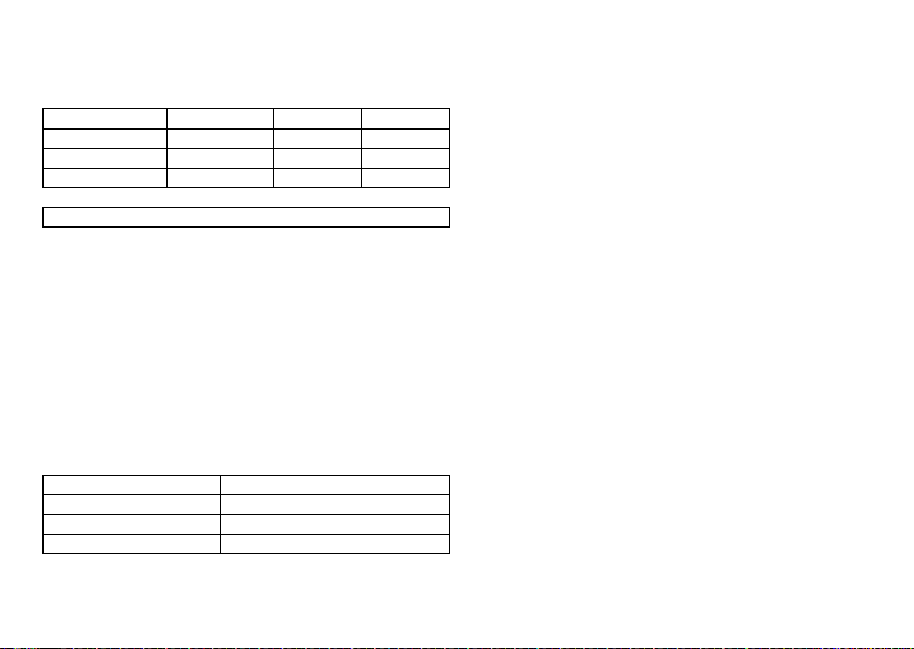
Mechanical Characteristics
Measurements for the housing
Device W x H x D [mm]
Single-chamber SR(-T) 53 x 39 x 6.5 11 24
Dual-chamber DR(-T) 53 x 44.5 x 6.5 12 25
Triple-chamber HF-T 53 x 49 x 6.5 14 27
Note:
D = housing without header
X-ray identification
BIO SF
Materials in contact with body tissue
•
Housing: titanium
•
Header: epoxy resin
•
Plugs in the header: silicone
Volume [cm3]
Electrical Characteristics
Electrically conductive surface
The device housing has the form of a flattened ellipsoid. The electrically conductive
area is 33 cm2.
Components and input values
Electrical characteristics determined at 37°C, 500 Ω:
Circuit Hybrid electronics with VLSI-CMOS chip
Input impedance > 10 kΩ
Pulse form Biphasic, asymmetric
Polarity Cathodic
en • English
Mass [g]
Telemetry data
•
MISC frequencies: 402 to 405 MHz
•
Maximum power of transmission: < 25 µW (–16 dBm)
International radio certification
Devices with BIOTRONIK Home Monitoring® are equipped with an antenna for wireless
communication.
•
Telemetry information for Canada:
This device must neither interfere with meteorological and earth resources technology satellites nor with meteorological stations working in the 400,150 to 406,000
MHZ band, and it must accept any interference received, including interference that
may cause undesired operation.
This device will be registered with Industry Canada under the following number:
IC: 4708A-PRIMUSNXT
The code IC in front of the certification/registration number only indicates that the
technical requirements for Industry Canada are met.
•
Telemetry information for Japan:
In accordance with Japanese law, this device has been assigned an identification
number under the "Ordinance concerning certification of conformity with technical
regulations etc. of specified radio equipment", Article 2-1-8.
R: 202-LSB053
•
Telemetry information for the USA:
Telemetry data for the USA: This transmitter is authorized by rule under the
Medical Device Radiocommunication Service (in part 95 of the FCC Rules) and must
not cause harmful interference to stations operating in the 400.150-406.000 MHz
band in the Meteorological Aids (i.e., transmitters and receivers used to communicate weather data), the Meteorological Satellite, or the Earth Exploration Satellite
Services and must accept interference that may be caused by such stations,
including interference that may cause undesired operation. This transmitter shall
be used only in accordance with the FCC Rules governing the Medical Device Radiocommunication Service. Analog and digital voice communications are prohibited.
Although this transmitter has been approved by the Federal Communications
Commission, there is no guarantee that it will not receive interference or that any
particular transmission from this transmitter will be free from interference.
This device will be registered with Federal Communications Commission under the
following number:
FCC ID: QRIPRIMUSNXT
23
Page 25

Pulse form
The pacing pulse has the following form:
The pulse amplitude reaches its maximum value
at the beginning of the pulse (Ua). With
increasing pacing duration (tb), the pulse
amplitude is reduced dependent on the pacing
impedance.
Resistance to interference
All variants of BIOTRONIK devices comply with the requirements of prEN 45502-2-1:
2006, § 27.5.1 at the highest sensitivity.
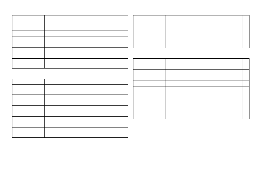
Battery Data
Battery characteristics
The following data is provided by the manufacturers:
Manufacturer LITRONIK GmbH, 01796 Pirna, Germany
Battery type LiS 3150M
System LiMn0
Device type SR(-T); DR(-T); HF-T
Battery voltage at BOS 3.1 V
Open-circuit voltage 3.1 V
Nominal capacity 1.2 Ah
Remaining capacity at ERI 0.2 Ah
Usable capacity until EOS 1.0 Ah
Shortening of the service time after long storage period
Depending on the storage period, the service time from the beginning of service BOS to
the replacement time ERI decreases as follows:
•
After 1 year by three months
•
After 1.5 years by four months
2
Power consumption
•
BOS, inhibited: SR(-T), DR(-T) 6 µA; HF-T: 7 µA
•
BOS, 100% pacing: SR(-T) 9 µA; DR(-T) 14 µA; HF-T: 18 µA
Calculation of service times
Mean service times are valid for devices with and without Home Monitoring; they are
pre-estimated from the following and other data:
•
Technical data of the battery manufacturer:
•
Basic rate of 60 bpm in AAIR/VVIR modes (single-chamber devices) or DDDR modes
(dual-chamber and triple-chamber devices)
•
Home Monitoring configuration: OFF
•
With 10-minute RF telemetry twice a year as well as without RF telemetry
•
Configuration of different pulse amplitudes and lead impedances
Mean service times SR(-T)
For single-chamber devices, the following times (in years) result:
Using RF telemetry:
Amplitude Impedance [Ω] Pacing
1.5 V 500 14.7 14.4 13.8
1000 14.9 14.8 14.4
2.5 V 500 14.1 13.5 11.8
1000 14.5 14.2 13.1
3.0 V 500 13.5 13.1 10.8
1000 14.2 13.6 12.4
3.5 V 500 13.1 12.8 10.1
1000 13.9 13.3 11.8
5.0 V 500 10.4 8.7 6.2
1000 12.1 10.8 8.3
10 % 50 % 100 %
24
Page 26

Without using RF telemetry:
Amplitude Impedance [Ω] Pacing
10 % 50 % 100 %
1.5 V 500 >15 >15 >15
1000 >15 >15 >15
2.5 V 500 >15 >15 13.3
1000 >15 >15 >15
3.0 V 500 >15 14.2 11.2
1000 >15 >15 14.1
3.5 V 500 14.9 12.9 10.1
1000 >15 >15 12.9
5.0 V 500 11.3 9.1 6.2
1000 14.5 12.5 9.4
Mean service times DR(-T)
For dual-chamber devices, the following times (in years) result:
Using RF telemetry:
Amplitude Impedance [Ω] Pacing
10 % 50 % 100 %
1.5 V 500 12.7 12.3 11.4
1000 12.9 12.8 12.2
2.5 V 500 11.8 11.0 8.9
1000 12.4 11.9 10.4
3.0 V 500 11.0 9.9 7.9
1000 11.9 11.2 9.7
3.5 V 500 10.5 9.3 7.1
1000 11.6 10.7 8.9
5.0 V 500 7.5 5.8 3.8
1000 9.3 7.8 5.5
Without using RF telemetry:
Amplitude Impedance [Ω] Pacing
1.5 V 500 >15 14.8 13.0
2.5 V 500 13.6 12.1 9.4
3.0 V 500 12.1 10.2 7.9
3.5 V 500 11.1 9.3 7.1
5.0 V 500 7.8 5.8 3.8
Mean service times HF-T
For triple-chamber devices, the following times (in years) result:
Using RF telemetry:
Pulse width: 0.4 ms
Amplitude:
A: 2.5 V
RV: 2.5 V
LV: 3.5 V
A: 2.5 V
RV: 2.5 V
LV: 2.5 V
1000 >15 >15 14.7
1000 >15 14.1 12.0
1000 14.2 12.7 10.1
1000 13.4 11.7 8.9
1000 10.7 8.7 5.9
Pacing Impedance:
atrial + biventric-
ular 100%
0% 7.8 8.4 9.3
30 % 7.5 8.1 9.1
50 % 7.3 7.9 8.9
100 % 6.9 7.5 8.6
0% 8.9 9.4 10.3
30 % 8.6 9.0 9.9
50 % 8.3 8.8 9.8
100 % 7.8 8.2 9.3
10 % 50 % 100 %
A+RV+LV:
500 Ω
A+RV: 500 Ω
LV: 800 Ω
A+RV+LV:
1000 Ω
en • English
25
Page 27

Pulse width: 0.4 ms
Amplitude:
A: 3.5 V
RV: 3.5 V
LV: 5 V
A: 2.0 V
RV: 2.2 V
LV: 2.4 V
A: 3.0 V
RV: 3.0 V
LV: 3.0 V
Without using RF telemetry:
Pulse width: 0.4 ms
Amplitude:
A: 2.0 V
RV: 2.2 V
LV: 2.4 V
A: 2.5 V
RV: 2.5 V
LV: 2.5 V
Pacing Impedance:
atrial + biventric-
ular 100%
0% 4.8 5.7 6.6
30 % 4.6 5.3 6.3
50 % 4.5 5.2 6.2
100 % 4.2 4.8 5.8
0% 9.1 9.5 10.3
30 % 8.8 9.2 10.0
50 % 8.6 8.9 9.9
100 % 8.1 8.4 9.6
0% 7.6 8.1 9.2
30 % 7.2 7.6 8.8
50 % 6.9 7.3 8.6
100 % 6.3 6.7 8.1
Pacing Impedance:
atrial + biventric-
ular 100%
0% 10.6 11.1 12.2
30 % 10.2 10.8 11.9
50 % 9.9 10.4 11.8
100 % 9.4 9.8 11.3
0% 10.3 10.8 12.0
30 % 9.8 10.4 11.7
50 % 9.6 10.1 11.4
100 % 9.0 9.4 10.9
A+RV+LV:
500 Ω
A+RV+LV:
500 Ω
A+RV: 500 Ω
LV: 800 Ω
A+RV: 500 Ω
LV: 800 Ω
A+RV+LV:
1000 Ω
A+RV+LV:
1000 Ω
Pulse width: 0.4 ms
Amplitude:
A: 2.5 V
RV: 2.5 V
LV: 3.5 V
A: 3.0 V
RV: 3.0 V
LV: 3.0 V
A: 3.5 V
RV: 3.5 V
LV: 5 V
26
Pacing Impedance:
atrial + biventric-
ular 100%
0% 8.8 9.8 10.8
30 % 8.5 9.3 10.6
50 % 8.3 9.1 10.4
100 % 7.8 8.6 10.0
0% 8.8 9.4 10.8
30 % 8.3 8.8 10.3
50 % 7.9 8.5 10.1
100 % 7.3 7.8 9.5
0% 5.3 6.4 7.7
30 % 5.1 6.1 7.3
50 % 4.9 5.8 7.2
100 % 4.6 5.3 6.8
A+RV+LV:
500 Ω
A+RV: 500 Ω
LV: 800 Ω
A+RV+LV:
1000 Ω
Page 28

Legend for the Label
NON
STERILE
Meaning of the symbols
Manufacturing date Use by
Storage temperature Order number
Serial number Product identification
European approval mark
Contents Consult the instructions for
Sterilized with ethylene oxide
Do not resterilize Single use only.
Do not use if packaging is
damaged
number
use
Do not reuse!
Non-sterile
Transmitter with non-ionizing radiation at
designated frequency
Label icon on devices with ProMRI®:
TP2
Compatibility with telemetry protocol version 2
of BIOTRONIK Home Monitoring
MR conditional: Patients having a device
system implanted whose components are
labeled with this symbol on the packaging
can be examined using an MR scan under
precisely defined conditions.
Uncoated device: NBG code and
compatible leads
Example
Coated device: NBG code and compatible
leads
Example
Screwdriver
Header
Example
Bipolar IS-1 connector
Unipolar IS-1 connector
en • English
27
Page 29

de • Deutsch
Produktbeschreibung . . . . . . . . . . . . . . . . . . . . . . . . . . . . . . . . . . . . . . . . . . . . . . . . . . . . 28
Medizinische Zweckbestimmung. . . . . . . . . . . . . . . . . . . . . . . . . . . . . . . . . . . . . 28
Indikationen. . . . . . . . . . . . . . . . . . . . . . . . . . . . . . . . . . . . . . . . . . . . . . . . . . . . . . 28
Kontraindikationen . . . . . . . . . . . . . . . . . . . . . . . . . . . . . . . . . . . . . . . . . . . . . . . . 29
Systemübersicht . . . . . . . . . . . . . . . . . . . . . . . . . . . . . . . . . . . . . . . . . . . . . . . . . . 30
Diagnostik- und Therapiefunktionen. . . . . . . . . . . . . . . . . . . . . . . . . . . . . . . . . . 32
Allgemeine Sicherheitshinweise. . . . . . . . . . . . . . . . . . . . . . . . . . . . . . . . . . . . . . . . . . . 34
Betriebsbedingungen . . . . . . . . . . . . . . . . . . . . . . . . . . . . . . . . . . . . . . . . . . . . . . 34
Mögliche Komplikationen. . . . . . . . . . . . . . . . . . . . . . . . . . . . . . . . . . . . . . . . . . . 34
Mögliche Risiken. . . . . . . . . . . . . . . . . . . . . . . . . . . . . . . . . . . . . . . . . . . . . . . . . . 35
Implantation. . . . . . . . . . . . . . . . . . . . . . . . . . . . . . . . . . . . . . . . . . . . . . . . . . . . . . . . . . . . 36
Implantationsablauf . . . . . . . . . . . . . . . . . . . . . . . . . . . . . . . . . . . . . . . . . . . . . . . 36
Vorsichtsmaßnahmen beim Programmieren . . . . . . . . . . . . . . . . . . . . . . . . . . . 38
Magnetverhalten . . . . . . . . . . . . . . . . . . . . . . . . . . . . . . . . . . . . . . . . . . . . . . . . . . 40
Nachsorgen . . . . . . . . . . . . . . . . . . . . . . . . . . . . . . . . . . . . . . . . . . . . . . . . . . . . . . 41
Patientenaufklärung. . . . . . . . . . . . . . . . . . . . . . . . . . . . . . . . . . . . . . . . . . . . . . . 41
Austauschindikationen . . . . . . . . . . . . . . . . . . . . . . . . . . . . . . . . . . . . . . . . . . . . . 42
Explantation und Implantatwechsel . . . . . . . . . . . . . . . . . . . . . . . . . . . . . . . . . . 43
Parameter . . . . . . . . . . . . . . . . . . . . . . . . . . . . . . . . . . . . . . . . . . . . . . . . . . . . . . . . . . . . . 43
Zeitsteuerung . . . . . . . . . . . . . . . . . . . . . . . . . . . . . . . . . . . . . . . . . . . . . . . . . . . . 43
Stimulation und Wahrnehmung. . . . . . . . . . . . . . . . . . . . . . . . . . . . . . . . . . . . . . 45
Frequenzadaption . . . . . . . . . . . . . . . . . . . . . . . . . . . . . . . . . . . . . . . . . . . . . . . . 47
MRT-Programm . . . . . . . . . . . . . . . . . . . . . . . . . . . . . . . . . . . . . . . . . . . . . . . . . . 47
Voreingestellte Programme. . . . . . . . . . . . . . . . . . . . . . . . . . . . . . . . . . . . . . . . . 48
Toleranzen der Parameterwerte . . . . . . . . . . . . . . . . . . . . . . . . . . . . . . . . . . . . . 49
Technische Daten . . . . . . . . . . . . . . . . . . . . . . . . . . . . . . . . . . . . . . . . . . . . . . . . . . . . . . . 49
Mechanische Kenndaten . . . . . . . . . . . . . . . . . . . . . . . . . . . . . . . . . . . . . . . . . . . 49
Elektrische Kenndaten . . . . . . . . . . . . . . . . . . . . . . . . . . . . . . . . . . . . . . . . . . . . . 50
Batteriedaten. . . . . . . . . . . . . . . . . . . . . . . . . . . . . . . . . . . . . . . . . . . . . . . . . . . . . 50
Legende zum Etikett. . . . . . . . . . . . . . . . . . . . . . . . . . . . . . . . . . . . . . . . . . . . . . . 53
Inhaltsverzeichnis
1 Produktbeschreibung
Medizinische Zweckbestimmung
Bestimmungsgemäße Anwendung
Etrinsa ist der Name einer Familie von implantierbaren Herzschrittmachern, die bei
allen Indikationen von bradykarden Herzrhythmusstörungen implantiert werden
können. Primäres Ziel der Therapie ist die Verbesserung klinisch manifestierbarer
Symptome der Patienten. Die Implantation des Schrittmachers ist eine symptomatische Therapie mit folgendem Ziel:
•
Kompensation von Bradykardien durch atriale, ventrikuläre oder AV-sequenzielle
Stimulation
•
Bei 3-Kammer-Implantaten zusätzlich: Resynchronisation der ventrikulären
Kammerkontraktion durch biventrikuläre Stimulation
Diagnose- und Therapieformen
Der Herzrhythmus wird automatisch überwacht und bradykarde Rhythmusstörungen
werden behandelt. Alle wesentlichen Therapieansätze aus Kardiologie und Elektrophysiologie sind in dieser Implantatfamilie vereint. BIOTRONIK Home Monitoring®
ermöglicht Ärzten ein Therapiemanagement rund um die Uhr.
Vorausgesetzte Fachkenntnisse
Außer den medizinischen Grundlagen sind detaillierte Kenntnisse über die Funktionsweise und die Einsatzbedingungen eines Implantatsystems erforderlich.
•
Nur medizinische Fachkräfte mit diesen besonderen Kenntnissen können Implantate bestimmungsgemäß anwenden.
•
Wenn diese Kenntnisse nicht vorhanden sind, müssen die Anwender geschult
werden.
Indikationen
Leitlinien kardiologischer Gesellschaften
Für aktive Implantate von BIOTRONIK gelten die allgemein anerkannten Methoden der
Differentialdiagnostik, die Indikationen sowie die Empfehlungen für die Herzschrittmachertherapie.
Maßgebliche Orientierung bieten die Leitlinien der Kardiologieverbände:
28
Page 30

•
Wir empfehlen, die von der Deutschen Gesellschaft für Kardiologie, Herz- und
Kreislaufforschung (DGK) und der European Society of Cardiology (ESC) veröffentlichten Indikationen zu beachten.
•
Desgleichen die der Heart Rhythm Society (HRS), des American College of Cardiology (ACC), der American Heart Association (AHA) sowie die anderer nationaler
Kardiologieverbände.
Implantattypen
Für folgende Symptomatik/Erwartung sind folgende Implantattypen indiziert:
Symptomatik/Erwartung SR DR HF
Desorientiertheit wegen Bradykardie x x x
Präsynkope x x x
Vorteil aus der Resynchronisation des rechten und
linken Ventrikels
Synkope x x x
Stimulationsarten
Für folgende Symptomatik sind folgende Stimulationsarten indiziert:
Symptomatik/Erwartung Stimulationsarten
Sick-Sinus-Syndrom 2-Kammer-Stimulation
AV-Block II. oder III. Grades; chronischer, symptoma-
tischer
Adams-Stokes-Syndrom 2-Kammer-Stimulation
Schenkelblock; symptomatischer bifaszikulärer, wenn
Tachyarrhythmie und andere Ursachen ausgeschlossen
wurden
•
Chronotrope Inkompetenz
•
Vorteil aus erhöhter Stimulationsfrequenz bei körperlicher Aktivität
Sinusknotenfunktionsstörung bei intakter AV- und intraventrikulärer Überleitung
de • Deutsch
2-Kammer-Stimulation
2-Kammer-Stimulation
Modus R oder CLS
Atriale Stimulation
x
Symptomatik/Erwartung Stimulationsarten
Bradykardie in Kombination mit Folgendem:
•
Normaler Sinusrhythmus mit nur seltenen Episoden
eines AV-Blocks oder Sinusknotenausfalls
•
Chronisches atriales Flimmern
•
Schwere körperliche Behinderung
MR conditional
Ein mit ProMRI® gekennzeichneter MR-conditional-Herzschrittmacher kann in der
MRT-Umgebung bedingt risikofrei verwendet werden, wenn er zusammen mit einem
vollständigen MR-conditional-Implantatsystem und in Übereinstimmung mit den
Anweisungen in dem MRT-Handbuch eingesetzt wird.
Ventrikuläre Stimulation
Kontraindikationen
Leitlinien
Es sind keine Kontraindikationen für die Implantation von multifunktionalen 1-, 2-oder
3-Kammer-Schrittmachern bekannt, vorausgesetzt, der Implantation geht eine Differentialdiagnostik gemäß der einschlägigen Leitlinien voran, und es werden keine den
Patienten gefährdende Modi oder Parameterkombinationen eingestellt.
Stimulationsarten und Parameter
Die Verträglichkeit und Wirksamkeit von Parameterkombinationen muss geprüft und
nach der Programmierung kontrolliert und gegebenenfalls angepasst werden:
Sachverhalt Kontraindizierte Stimulationsart
Zusätzlich implantierter ICD Unipolare Stimulation
Sachverhalt Unzweckmäßige Stimulationsart
Chronische atriale Tachykardien, chronisches atriales Flimmern oder Flattern
Schlechte Toleranz von Stimulationsfrequenzen oberhalb der Grundfrequenz,
beispielsweise bei Angina pectoris
AV-Leitungsstörung Atriale 1-Kammer-Stimulation
Nachlassende AV-Überleitung
Vorhofgesteuerte Modi (DDD, VDD, AAI)
29
Page 31

Sachverhalt Parameter anpassen
VVIR /AAIR
IS-1
DDDR
A
IS-1
DDDR
A
IS-1
V
LV
RV
Langsame retrograde Überleitung nach
ventrikulärer Stimulation: Gefahr schrittmacherinduzierter Tachykardien
Schlechte Toleranz von Stimulationsfrequenzen oberhalb der Grundfrequenz,
beispielsweise bei Angina pectoris
•
Atriale Refraktärzeit verlängern
und/oder:
•
AV-Zeit verkürzen
•
Seltener:
DDI, DVI oder VVI programmieren
•
Obere Grenzfrequenz verringern
•
Maximale Sensorfrequenz verringern
•
Atriale Überstimulation einsetzen
Systemübersicht
Implantatfamilie
Diese Implantatfamilie besteht aus 1-, 2- und 3-Kammer-Implantaten, mit oder ohne
Home Monitoring. Nicht in jedem Land sind alle Implantattypen erhältlich.
Es gibt folgende Implantatvarianten:
Implantattyp Varianten mit
Home Monitoring
1-Kammer Etrinsa 8 SR-T, Etrinsa 6 SR-T Etrinsa 6 SR
2-Kammer Etrinsa 8 DR-T, Etrinsa 6 DR-T Etrinsa 6 DR
3-Kammer Etrinsa 8 HF-T —
Implantat
Das Gehäuse des Implantats ist aus biokompatiblem Titan, von außen verschweißt und
somit hermetisch versiegelt. Die ellipsoide Form erleichtert das Einwachsen in den
Brustmuskelbereich. Das Gehäuse dient bei unipolarer Elektrodenkonfiguration als
Gegenpol.
Varianten ohne
Home Monitoring
Elektrodenanschluss IS-1
Die Beschriftung des Implantats gibt Auskunft über die Anordnung der Anschlüsse:
SR DR HF
Anschluss Stecker Konfiguration Implantationsort Implantattyp
RA IS-1 Unipolar, bipolar Atrium DR, HF
RV IS-1 Unipolar, bipolar Rechter Ventrikel SR, DR, HF
LV IS-1 Unipolar, bipolar Linker Ventrikel HF
Hinweis:
Für Elektroden mit anderen Anschlüssen verwenden Sie nur die von
BIOTRONIK zugelassenen Adapter.
•
Mit Fragen zur Kompatibilität von Elektroden anderer Hersteller wenden Sie sich
bitte an BIOTRONIK.
Elektroden
Die Elektroden von BIOTRONIK sind mit biokompatiblem Silikon ummantelt. Sie sind
flexibel zu manövrieren, langzeitstabil und für aktive oder passive Fixierung ausgestattet. Sie werden mit Hilfe eines Einführbestecks implantiert. Einige Elektroden sind
zur besseren Gleitführung mit Polyurethan beschichtet. Elektroden mit Steroiden
reduzieren entzündliche Prozesse. Die fraktale Ausführung der Elektroden sorgt für
niedrige Reizschwellen, hohe Stimulationsimpedanz und geringes Oversensing-Risiko.
BIOTRONIK bietet Adapter an, um bereits liegende Elektroden an neue Implantate
anzuschließen.
30
Page 32

Telemetrie
Die telemetrische Kommunikation zwischen Implantat und Programmiergerät ist nach
der Initialisierung sowohl mittels Auflage eines Programmierkopfs (PGH, programming
head) als auch mittels RF-Telemetrie (Hochfrequenztelemetrie) möglich; diese Funktion heißt bei BIOTRONIK SafeSync®.
Programmiergerät
Implantiert und nachgesorgt wird mit dem transportablen Programmiergerät von
BIOTRONIK: Es gibt Programmiergeräte mit integriertem oder externem SafeSyncModule für die RF-Telemetrie.
Mit Hilfe des Programmiergeräts wird bei der Implantation die aktuelle Software auf
das Implantat übertragen. Es können die Reizschwellen festgestellt und alle Tests
während einer Präsenznachsorge durchgeführt werden. Das Programmiergerät dient
darüber hinaus der Einstellung von Modus und Parameterkombinationen sowie der
Abfrage und Speicherung von Daten aus dem Implantat. Auf dem Farbdisplay werden
gleichzeitig kabelloses EKG, IEGM, Marker und Funktionen angezeigt.
Modi
Die Einstellung des Modus hängt von der individuellen Diagnose ab:
Implantattyp Modi Standard
SR(-T)
DR(-T)
•
VVI-CLS (nur 8er-Serie)
•
VVIR; V00R; AAIR; A00R
•
VVI; VVT; V00; AAI; AAT; A00
•
AUS
•
VVI-CLS; DDD-CLS (nur 8er-Serie)
•
DDDR; DDIR; DVIR; D00R
VDDR; VDIR; VVIR; V00R
AAIR; A00R
•
DDD; DDT; DDI; DVI; D00
VDD; VDI; VVI; VVT; V00
AAI; AAT; A00
•
DDD-ADI; DDDR-ADIR
•
AUS
VVIR
DDDR
Implantattyp Modi Standard
HF-T
Hinweis:
NBG-Codes
AAIR oder VVIR lautet der NBG-Code für den antibradykarden Modus des 1-KammerImplantats:
A/V Stimulation im Atrium oder im Ventrikel
A/V Wahrnehmung im Atrium oder im Ventrikel
I Impulsinhibierung im Atrium und im Ventrikel
R Frequenzadaption
DDDR lautet der NBG-Code für den antibradykarden Modus des 2-Kammer-Implantats:
D Stimulation im Atrium und im Ventrikel
D Wahrnehmung im Atrium und im Ventrikel
D Impulsinhibierung und Impulstriggerung
R Frequenzadaption
•
DDD-CLS; VVI-CLS
•
DDDR; DDIR; DVIR; D00R
VDDR; VDIR; VVIR; V00R
AAIR; A00R
•
DDD; DDT; DDI; DVI; D00
VDD; VDI; VVI; VVT; V00
AAI; AAT; A00
•
DDD-ADI; DDDR-ADIR
•
AUS
Home Monitoring ist in allen Modi möglich.
DDDR
de • Deutsch
31
Page 33

DDDRV lautet der NBG-Code für den antibradykarden Modus des 3-Kammer-Implantats:
D Stimulation im Atrium und im Ventrikel
D Wahrnehmung im Atrium und im Ventrikel
D Impulsinhibierung und Impulstriggerung
R Frequenzadaption
V Multisite-Stimulation in beiden Ventrikeln
BIOTRONIK Home Monitoring
Über die effektive Stimulationstherapie hinaus stellt BIOTRONIK ein komplettes Therapiemanagement zur Verfügung:
•
Beim Home Monitoring werden diagnostische und therapeutische Informationen
sowie technische Daten des Implantats automatisch und drahtlos mittels einer
Antenne im Anschlussblock des Implantats an ein stationäres oder ein mobiles
Patientengerät gesendet. Vom Patientengerät werden die Daten verschlüsselt und
via Mobilfunknetz an das BIOTRONIK Service Center gesendet.
•
Die empfangenen Daten werden entschlüsselt und ausgewertet; jeder Arzt kann für
jeden Patienten individuell einstellen, nach welchen Kriterien ausgewertet werden
und wann er per E-Mail, SMS oder Fax benachrichtigt werden soll.
•
Die Ergebnisse dieser Auswertung werden für die behandelnden Ärzte auf der
geschützten Internetplattform HMSC (Home Monitoring Service Center) übersichtlich dargestellt.
•
Die Datenübertragung vom Implantat aus erfolgt mit einer täglichen Implantatnachricht.
•
Implantatnachrichten, die auf besondere Ereignisse im Herzen des Patienten oder
im Implantat hinweisen, werden sofort weitergeleitet.
•
Jederzeit kann vom Programmiergerät aus zur Sofortkontrolle der Home-Monitoring-Funktion eine Testnachricht initiiert werden.
®
Bestellnummern Etrinsa
Die Implantate sind wie folgt erhältlich:
Implantattyp Etrinsa 6 Etrinsa 6
SR 394940 394984 — —
SR-T 394938 394983 394936 394978
DR 394928 394982 — —
DR-T 394933 394981 394931 394977
HF-T — — 394919 394976
Lieferumfang
In der Lagerverpackung befinden sich:
•
Sterilverpackung mit Implantat
•
Seriennummernaufkleber
•
Patientenausweis
•
Garantieheft
Hinweis:
Die Gebrauchsanweisung zum Implantat liegt entweder gedruckt in der
Lagerverpackung oder digital im Internet.
In der Sterilverpackung befinden sich:
•
Implantat
•
Schraubendreher
ProMRI
Etrinsa 8 Etrinsa 8
ProMRI
Diagnostik- und Therapiefunktionen
Allgemeiner Überblick
Alle Systeme verfügen über umfangreiche Funktionen zur schnellen Diagnose und
sicheren Therapie von Bradykardien.
•
Durch automatische Funktionen ist der Herzschrittmacher problemlos und zeitsparend zu implantieren, einzustellen und zu kontrollieren.
•
Auto-Initialisierung nach der Implantation: Das Implantat erkennt die implantierten
Elektroden selbstständig und stellt die Polarität ein. Die Automatikfunktionen der
Software werden nach 10 min aktiviert.
32
Page 34

Diagnostikfunktionen
•
Daten der letzten 10 Abfragen und Nachsorgen werden ebenso aufgezeichnet wie
Arrhythmieepisoden; sie werden zusammen mit weiteren Daten gespeichert, um
sowohl Patienten als auch Implantatzustand jederzeit beurteilen zu können.
•
Zur Kontrolle der Funktionsfähigkeit der Elektroden wird die Impedanz im
Implantat – unabhängig von einem Stimulationsimpuls – automatisch und
kontinuierlich unterschwellig gemessen.
•
Bei Präsenznachsorgen wird nach dem Herstellen einer Telemetrieverbindung
während des Testablaufs das IEGM mit Markern angezeigt.
Antibradykardie-Stimulation
•
Wahrnehmung: Die Amplituden von P- und R-Welle werden im Implantat permanent vollautomatisch gemessen, um auch wechselnde Amplituden zu erfassen. Die
Empfindlichkeit für Atrium und Ventrikel wird ebenso vollautomatisch kontinuierlich angepasst. Die Messdaten werden gemittelt und der Trend kann angezeigt
werden.
•
Reizschwellen: Sowohl atriale als auch ventrikuläre Reizschwellen werden im
Implantat automatisch ermittelt; mittels Amplitudensteuerung werden die
Impulsamplituden so eingestellt, dass auf jede Reizschwellenänderung mit der für
den Patienten optimalen atrialen und ventrikulären Amplitude stimuliert wird.
•
Zeitsteuerung: Zur Vermeidung schrittmacherinduzierter Tachykardien wird die
Stimulation im Atrium durch automatische Anpassung der atrialen Refraktärzeit
besonders kontrolliert (Funktion Auto-PVARP: automatische postventrikuläre
atriale Refraktärzeit).
•
Zusätzliche, besondere Form der Frequenzadaption bei Implantaten der 8er Serie:
Ein erhöhter Herzminutenvolumen-Bedarf wird anhand einer physiologischen
Impedanzmessung erkannt. Das Messprinzip beruht auf der geänderten Kontraktilität (Inotropie) des Myokards (Funktion CLS: Closed-Loop-Stimulation). Die
Frequenzadaption wird im CLS-Modus automatisch initialisiert und optimiert.
•
Ventrikuläre Stimulationsunterdrückung: Unnötige ventrikuläre Stimulation wird
durch Förderung der intrinsischen Überleitung vermieden (Funktion Vp-Unterdrückung). Dabei kann sich das Implantat an Überleitungsveränderungen
anpassen. Bei intrinsischer Überleitung wechselt das Implantat in einen
DDD(R)-ADI(R)-Modus.
Resynchronisationstherapie
3-Kammer-Implantate haben zur Resynchronisation der Ventrikel Funktionen zur
Einstellung verschiedener VV-Zeiten.
•
Es gibt die automatische Amplitudensteuerung auch für den linken Ventrikel mit
automatischer Verfolgung der Reizschwelle oder mit automatischer Reizschwellenüberwachung (ATM) zwecks Trendanalyse.
•
Damit bei einer linksseitigen Reizschwellenerhöhung oder ungewollter PhrenicusStimulation keine erneute Operation nötig ist, kann man bei einem
3-Kammer-Implantat für die linksventrikuläre Elektrode unterschiedliche Stimulationspolaritäten einstellen.
•
Zusätzliche diagnostische Funktion bei biventrikulärer Stimulation: Variabilität der
Herzfrequenz, die Patientenaktivität und die Thoraximpedanz werden kontinuierlich überwacht.
Programme
Es gibt zwei Arten von Therapieprogrammen:
•
Für die häufigsten Indikationen werden voreingestellte Parameter angeboten
(Funktion ProgramConsult).
•
Individuelle Einstellungen lassen sich in 3 individuellen Therapieprogrammen
speichern.
Funktionen von Home Monitoring
Automatisch sendet das Implantat einmal täglich Informationen an das Patientengerät.
Zusätzlich können Testnachrichten mit Hilfe des Programmiergeräts initiiert werden.
Wichtige medizinische Informationen sind unter anderen folgende:
•
Anhaltende atriale und ventrikuläre Arrhythmien
•
Elektrodenrelevante Parameter im Atrium und Ventrikel: Reizschwellen, Wahrnehmungsamplituden, Impedanzen
•
Aktuelle Statistiken zur Bradykardietherapie
•
Individuell einstellbares Zeitintervall für Implantatnachrichten, welche die reguläre
Implantatnachricht um zusätzliche Informationen bereichern
•
IEGM-Online HD® mit bis zu 3 Kanälen in hoher Auflösung (High Definition)
•
Sendung der IEGM-Aufzeichnungen mit den Implantatnachrichten
de • Deutsch
33
Page 35

2 Allgemeine Sicherheitshinweise
Betriebsbedingungen
Gebrauchsanweisungen
Folgende Gebrauchsanweisungen informieren über die Anwendung von Implantatsystemen:
— Gebrauchsanweisung zum Implantat
— Gebrauchsanweisung zum HMSC
— Gebrauchsanweisungen zum Programmiergerät und zu dessem Zubehör
— Gebrauchsanweisungen zur Benutzeroberfläche
— Gebrauchsanweisungen zu Kabeln, Adaptern und Zubehör
•
Gebrauchsanweisungen liegen entweder gedruckt in der Lagerverpackung oder
digital im Internet:
manuals.biotronik.com
•
Alle relevanten Gebrauchsanweisungen beachten.
•
Gebrauchsanweisungen für späteren Gebrauch aufbewahren.
Aufbewahrung bei Transport und Lagerung
•
Implantate dürfen nicht in der Nähe von Magneten oder elektromagnetischen Störquellen gelagert werden.
•
Auswirkungen der Lagerdauer beachten, siehe Batteriedaten.
Temperatur
Sowohl extrem niedrige als auch hohe Temperaturen wirken sich auf die Betriebszeit
der Batterie im Implantat aus.
•
Zulässig für Transport und Lagerung sind:
-10 ºC bis 45 ºC
Sterile Auslieferung
Implantat und Schraubendreher werden gassterilisiert ausgeliefert. Die Sterilität ist
gewährleistet, wenn Blister und Qualitätskontrollsiegel nicht beschädigt sind.
Sterilverpackung
Implantat und Schraubendreher sind in 2 separat versiegelten Blistern verpackt: Der
innere Blister ist auch außen steril, damit er bei der Implantation steril übergeben
werden kann.
Einmalverwendung
Implantat und Schraubendreher sind nur zur Einmalverwendung vorgesehen.
•
Implantat nicht verwenden, wenn die Verpackung beschädigt ist.
•
Implantat nicht resterilisieren und nicht wiederverwenden.
Mögliche Komplikationen
Allgemeines zu medizinischen Komplikationen
Für Implantate von BIOTRONIK gelten die in der Fachpraxis allgemein bekannten
Komplikationen für Patienten und Implantatsysteme.
•
Komplikationen sind beispielsweise Flüssigkeitsansammlungen in der Implantattasche, Infektionen oder Gewebereaktionen. Maßgebliche Orientierung sind Stand
der Wissenschaft und Technik.
•
Garantieren kann man die Zuverlässigkeit von Antiarrhythmietherapie nicht, auch
wenn während der Tests oder späterer elektrophysiologischer Untersuchungen
die Programme erfolgreich waren. Unter seltenen Umständen können die eingestellten Parameter ineffektiv werden. Insbesondere lässt sich nicht ausschließen,
dass Tachyarrhythmien induziert werden.
Skelettmuskelpotenziale
Bipolare Wahrnehmung und Kontrolle der Empfindlichkeit werden vom Implantat so
auf den Frequenzbereich der Herzeigenaktionen abgestimmt, dass Skelettmuskelpotenziale in der Regel nicht wahrgenommen werden. Dennoch können – vor allem bei
unipolarer Konfiguration und/oder bei sehr hoher Empfindlichkeit – Skelettmuskelpotenziale als Herzeigenaktionen klassifiziert werden und – je nach Interferenz –
Inhibierung oder Antiarrhythmietherapie bewirken.
Nerven- und Muskelstimulation
Ein Implantatsystem aus unipolarer Elektrode und nicht beschichtetem Implantat kann
bei einer anfänglich oder dauerhaft hohen Einstellung der Impulsamplitude zu unerwünschter Stimulation des Zwerchfells führen.
Mögliche technische Fehlfunktionen
Fehlfunktionen eines Implantatsystems können grundsätzlich nicht ausgeschlossen
werden. Ursachen können unter anderem folgende sein:
•
Elektrodendislokation
•
Elektrodenbruch
•
Isolierungsdefekte
•
Komponentenfehler des Implantats
•
Batterieerschöpfung
34
Page 36

Elektromagnetische Interferenz EMI
Jedes Implantat kann gestört werden, beispielsweise wenn äußere Signale als Eigenrhythmus wahrgenommen werden oder wenn Messungen die Frequenzanpassung
behindern:
•
Implantate von BIOTRONIK sind so konstruiert, dass ihre Beeinflussbarkeit durch
EMI minimal ist.
•
Wegen der vielen Arten und Intensitäten von EMI gibt es keine absolute Sicherheit.
Allgemein geht man davon aus, dass EMI – wenn überhaupt – nur geringfügige
Symptome bei Patienten verursacht.
•
Je nach Stimulationsart und Art der Interferenz können Störquellen zu einer
Impulsinhibierung oder -triggerung, zum Anstieg der sensorabhängigen Stimulationsfrequenz oder zu asynchroner Stimulation führen.
•
Unter ungünstigen Bedingungen, besonders im Rahmen diagnostischer und therapeutischer Maßnahmen, können Störquellen eine so hohe Energie einkoppeln, dass
Gewebe, welches das Implantat oder die Elektrodenspitze umgibt, geschädigt wird.
Verhalten des Implantats bei EMI
Bei elektromagnetischen Interferenzen oder unerwünschten Muskelpotenzialen
schaltet das Implantat für die Dauer der Überschreitung der Interferenzfrequenz auf
asynchrone Stimulation.
Statische magnetische Felder
Der Reedkontakt im Herzschrittmacher schließt ab einer Feldstärke von 1,5 mT.
Mögliche Risiken
Zu vermeidende Verfahren
Wegen möglicher Schädigung des Patienten oder des Implantats und daraus resultierender Funktionsunsicherheit müssen folgende Verfahren vermieden werden:
•
Therapeutischer Ultraschall
•
Transkutane elektrische Nervenstimulation
•
Hyperbare Sauerstofftherapie
•
Druckbelastungen über Normaldruck
Risikobehaftete Therapie- und Diagnoseverfahren
Wenn für diagnostische oder therapeutische Zwecke elektrischer Strom von einer
externen Quelle durch den Körper geleitet wird, können das Implantat gestört und der
Patient gefährdet werden.
Bei diathermischen Verfahren wie zum Beispiel Elektrokauterisierung, HF-Ablation
oder HF-Chirurgie ist eine Induktion von Arrhythmien oder Kammerflimmern möglich.
Bei zum Beispiel Lithotripsie ist eine schädliche Druckwirkung möglich. Auswirkungen
auf das Implantat kann man manchmal nicht sofort feststellen.
Wenn risikobehaftete Verfahren nicht zu vermeiden sind, gilt deshalb immer:
•
Patienten elektrisch isolieren.
•
Die Schrittmacherfunktion gegebenenfalls auf asynchrone Modi umstellen.
•
Keine Energie in die Nähe des Implantatsystems einbringen.
•
Zusätzlich peripheren Puls des Patienten kontrollieren.
•
Patienten bei und nach jedem Eingriff überwachen.
Externe Defibrillation
Das Implantat ist gegen die Energie geschützt, die eine externe Defibrillation normalerweise induziert. Externe Defibrillation kann jedoch jedes Implantat schädigen.
Insbesondere Strominduktion in die implantierten Elektroden kann Nekrosen im
Einwachsbereich hervorrufen, was wiederum zu veränderten Wahrnehmungseigenschaften und Reizschwellen führt.
•
Klebeelektroden anterior-posterior oder senkrecht zur Verbindungslinie vom
Implantat zum Herzen sowie mindestens 10 cm vom Implantat und von den implantierten Elektroden entfernt platzieren.
Strahlentherapie
Die Anwendung von therapeutischer Bestrahlung ist wegen möglicher Schädigung des
Implantats und daraus resultierender Funktionsunsicherheit zu vermeiden. Sollte
diese Therapieart dennoch angewendet werden, ist eine vorherige Risiko-NutzenAbwägung unabdingbar. Die Komplexität der Einflussfaktoren – zum Beispiel unterschiedliche Strahlenquellen, Implantatvielfalt, Therapiebedingungen – macht es nicht
möglich, Richtlinien zu verabschieden, die eine Strahlentherapie ohne Auswirkungen
auf das Implantat garantieren. Die Norm EN 45502 über aktive implantierbare Medizingeräte fordert im Zusammenhang mit therapeutischer ionisierender Strahlung
folgende Maßnahmen:
•
Hinweise zu risikobehafteten Therapie- und Diagnoseverfahren beachten.
•
Implantat gegen Strahlen abschirmen.
•
Nach der Strahlenapplikation das Implantatsystem wiederholt auf Funktionsfähigkeit prüfen.
Hinweis:
Mit Fragen bei der Risiko-Nutzen-Abwägung bitte an BIOTRONIK wenden.
de • Deutsch
35
Page 37

Magnetresonanztomografie
Magnetresonanztomografie (MRT) muss wegen der damit verbundenen Hochfrequenzfelder und magnetischen Flussdichten vermieden werden: Schädigung oder Zerstörung
des Implantatsystems durch starke magnetische Wechselwirkung und Schädigung des
Patienten durch übermäßige Erwärmung des Körpergewebes im Bereich des Implantatsystems.
Unter bestimmten Bedingungen kann man bei Einhaltung vorgeschriebener Maßnahmen zum Schutz von Patient und Implantatsystem eine Magnetresonanztomografie
durchführen. Bei BIOTRONIK haben Implantate mit der Funktion „MR conditional“ die
Kennung ProMRI®.
•
Das Handbuch ProMRI® – MR-conditional-Implantatsysteme – enthält ausführliche Informationen über die sichere Durchführung einer MRT.
—
Digitales Handbuch von der Website laden:
manuals.biotronik.com
—
Gedrucktes Handbuch bei BIOTRONIK bestellen.
•
Gilt die Zulassung als "MR conditional" in Ihrem Land oder Ihrer Region?
Aktuelle Informationen bei BIOTRONIK anfordern.
3 Implantation
Implantationsablauf
Teile bereitlegen
Folgende der EG-Richtlinie 90/385/EEC entsprechende Teile werden benötigt:
•
Implantat mit Schraubendreher von BIOTRONIK
•
Elektroden von BIOTRONIK und Einführbesteck
—
1-Kammer-Implantat: uni- oder bipolare Elektrode für den rechten Ventrikel
—
2-Kammer-Implantat: je eine uni- oder bipolare Elektrode für das Atrium und
für den rechten Ventrikel
—
3-Kammer-Implantat: zusätzlich eine uni- oder bipolare LV-Elektrode
•
Zulässige Anschlüsse sind IS-1: Für Elektroden mit anderen Anschlüssen oder
Elektroden anderer Hersteller nur die von BIOTRONIK zugelassenen Adapter
verwenden.
•
Programmiergerät von BIOTRONIK (mit integrierter SafeSync-RF-Telemetrie oder
mit separatem SafeSync Module) und zugelassene Kabel
•
Externes Mehrkanal-EKG-Gerät
•
Für sterile Teile Ersatz in Reserve halten.
Externen Defibrillator bereithalten
Zur Reaktion auf unvorhersehbare Notfälle oder auf eventuelle Fehlfunktionen des
Implantats:
•
Externen Defibrillator und Paddles oder Klebeelektroden bereithalten.
Implantat auspacken
W
WARNUNG
Inadäquate Therapie wegen defekten Implantats
Wenn ein ausgepacktes Implantat beim Hantieren herunterfällt und auf eine harte
Oberfläche aufschlägt, könnten elektronische Teile beschädigt sein.
•
Ersatzimplantat verwenden.
•
Beschädigtes Implantat an BIOTRONIK schicken.
•
Papierverschluss des äußeren Blisters an der markierten Stelle in Pfeilrichtung
abziehen. Der innere Blister darf nicht von unsterilen Personen oder Instrumenten
berührt werden!
•
Inneren Blister an der Griffmulde anfassen und aus Außenblister nehmen.
•
Papierverschluss des sterilen inneren Blisters an der markierten Stelle in Pfeilrichtung abziehen.
Hinweis:
Das Implantat ist im Auslieferungszustand deaktiviert und kann sofort nach
dem Auspacken ohne manuelle Aktivierung implantiert werden.
Teile prüfen
Beschädigungen an einem der Teile können zu Komplikationen oder Fehlfunktionen
führen.
•
Vor und nach dem Auspacken alle Teile auf Beschädigungen prüfen.
•
Beschädigte Teile austauschen.
Situs
In der Regel werden Herzschrittmacher subkutan oder subpektoral rechts implantiert,
abhängig von der Elektrodenkonfiguration und der Anatomie des Patienten.
36
Page 38

Überblick: Implantieren
1 Implantattasche formen und Vene präparieren.
2 Elektroden implantieren und Messungen durchführen.
3 Implantat und Elektroden verbinden.
Das Implantat startet selbstständig die Auto-Initialisierung.
4 Implantat einsetzen.
5 Fixierfaden durch die Öffnung im Anschlussblock führen und das Implantat in
der vorbereiteten Tasche fixieren.
6 Implantattasche verschließen.
7 Vor Tests und Einstellungen den erfolgreichen Abschluss der automatischen
Initialisierung des Implantats abwarten.
Hinweis:
Falls erforderlich, kann das Implantat auch vor oder während der Auto-
Initialisierung programmiert werden.
Anschlussblock nicht beschädigen
Anschlussschrauben müssen sorgfältig angezogen oder gelöst werden.
•
Anschlussschrauben mit dem mitgelieferten Schraubendreher lösen.
Nur Schraubendreher mit Drehmomentbegrenzung von BIOTRONIK benutzen!
•
Im Fall einer notwendigen Elektrodenrevision bei BIOTRONIK sterile Schraubendreher nachbestellen.
Kurzschluss im Anschlussblock vermeiden
W
WARNUNG
Kurzschluss durch offene Elektrodenanschlüsse
Offene und dadurch nicht elektrolytdichte Anschlüsse im Anschlussblock können
unerwünschte Stromflüsse zum Körper und das Eindringen von Körperflüssigkeit in
das Implantat verursachen.
•
Nicht genutzte Anschlüsse mit IS-1- Blindsteckern verschließen.
Abstand zwischen Elektroden wahren
W
WARNUNG
Unzureichende Therapie
Wenn Elektroden nicht genügend Abstand voneinander haben oder ungünstig positioniert sind, kann das zu Far-field-Wahrnehmung führen.
•
Tip- und Ringelektroden dürfen sich nicht berühren.
Elektrodenstecker an Implantat anschließen
1 Mandrins und Einführhilfen entfernen.
2•Den uni- oder bipolaren IS-1-Stecker Ventrikel an RV anschließen.
•
Den uni- oder bipolaren IS-1-Stecker Atrium an A anschließen.
•
Den uni- oder bipolaren IS-1-Stecker Ventrikel an LV anschließen.
3 Elektrodenstecker – ohne die Zuleitung zu knicken – in den Anschlussblock
schieben, bis die Steckerspitze hinter dem Schraubenblock zu sehen ist.
4 Lässt sich der Stecker nicht vollständig einführen, ragt möglicherweise die
Anschlussschraube in die Bohrung des Schraubenblocks. Die Anschlussschraube vorsichtig lösen, ohne sie vollständig herauszudrehen, damit sie beim
Hereindrehen nicht verkantet.
5 Den Silikonstopfen in der Mitte an der geschlitzten Stelle mit dem Schrauben-
dreher senkrecht bis zur Anschlussschraube durchstechen.
6 Die Anschlussschraube im Uhrzeigersinn drehen, bis die Drehmoment-
begrenzung einsetzt (knackendes Geräusch).
7 Den Schraubendreher vorsichtig herausziehen, ohne dabei die Anschluss-
schraube zurückzudrehen.
•
Nach dem Zurückziehen des Schraubendrehers dichtet der Silikonstopfen
den Elektrodenanschluss selbstständig sicher ab.
Programmierkopf auflegen
Auf dem Programmierkopf (PGH) befindet sich eine schematische Zeichnung des
Implantats. Diese dient als Positionierhilfe bei der Auflage, um eine korrekte Telemetrie sicherzustellen.
•
Auf eine richtige Positionierung des PGHs achten.
de • Deutsch
37
Page 39

Telemetrie herstellen
Das Programmiergerät (oder das SafeSync Module) darf minimal 20 cm und maximal
3 m vom Implantat entfernt sein; am besten befinden sich keine Hindernisse zwischen
Patient und Programmiergerät.
•
Die RF-Telemetrie am Programmiergerät einschalten.
•
Den Programmierkopf etwa 2 s auflegen, bis die erfolgreiche Initialisierung am
Programmiergerät angezeigt wird:
Im Navigator ist das Symbol für SafeSync zu sehen und in der Statuszeile
eine Anzeige für die Signalstärke.
•
Den Programmierkopf weglegen.
Auto-Initialisierung
Wenn die erste angeschlossene Elektrode wahrgenommen wird, beginnt automatisch
die Auto-Initialisierung.
10 min nach Anschluss der ersten Elektrode wird die Auto-Initialisierung beendet.
Falls zwischenzeitlich kein anderes Programm übertragen wurde, arbeitet das
Implantat anschließend mit aktiven Automatikfunktionen im Werksprogramm oder im
vom Anwender voreingestellten Programm.
Eine manuelle Einstellung der Elektrodenpolarität oder eine Messung der Elektrodenimpedanzen ist nicht erforderlich.
Hinweis:
Nach der Auto-Initialisierung sind alle Parameter wie im Werksprogramm
aktiviert.
Verhalten während der Auto-Initialisierung
•
Bei Übertragung eines Permanentprogramms:
Die Auto-Initialisierung wird beendet und das übertragene Programm ist aktiv.
•
Durchführung von Tests:
Tests sind während der Auto-Initialisierung nicht möglich; sie muss erst abgebro-
chen werden. Die Auto-Initialisierung wird anschließend nicht fortgesetzt.
Vorsichtsmaßnahmen beim Programmieren
Implantatsystem prüfen
•
Nach der Auto-Initialisierung eine Nachsorge durchführen, um die ordnungsgemäße Funktionsfähigkeit des Implantatsystems festzustellen.
•
Zur Feststellung der Reizschwelle einen Reizschwellentest durchführen.
Standardtests machen und Patienten überwachen
Auch während der Standardtests kann beispielsweise wegen der Einstellung inadäquater Parameter oder wegen einer Telemetriestörung ein für den Patienten kritischer
Zustand auftreten.
•
Auch bei Tests auf ausreichende Patientenversorgung achten.
•
Nach dem Reizschwellentest prüfen, ob die Schwelle klinisch und technisch
vertretbar ist.
•
Das EKG und den Zustand des Patienten kontinuierlich überwachen.
•
Gegebenenfalls den Test abbrechen.
Telemetrie während einer Behandlung nicht unterbrechen
Durch Trennen des SafeSync Modules vom Programmiergerät kann es zu einer gestörten oder abgebrochenen SafeSync-RF-Telemetrie kommen.
•
Das SafeSync Module nicht vom Programmiergerät trennen.
•
Das Operation Module nicht vom ICS 3000 abnehmen.
Telemetrie abbrechen
Eine Programmiergeräte- oder Telemetriestörung, die während der Ausführung von
Temporärprogrammen (Nachsorgetests) auftritt, kann zu inadäquater Stimulation des
Patienten führen. Das ist dann der Fall, wenn sich das Programmiergerät durch einen
Programmfehler oder Touchscreen-Defekt nicht mehr bedienen und demzufolge das
Temporärprogramm nicht beenden lässt. Dann hilft der Abbruch der Telemetrie, wobei
das Implantat automatisch in das Permanentprogramm schaltet.
•
Bei Telemetrie mit PGH: Den Programmierkopf um mindestens 30 cm abheben.
•
Bei RF-Telemetrie: Das Programmiergerät ausschalten und repositionieren.
•
Mögliche Störquellen ausschalten.
38
Page 40

Kritische Parametereinstellungen vermeiden
Es dürfen keine den Patienten gefährdenden Modi und Parameterkombinationen
eingestellt werden.
•
Vor der Einstellung der Frequenzadaption die Belastungsgrenzen des Patienten
feststellen.
•
Die Verträglichkeit und Wirksamkeit von Parameterkombinationen nach der
Einstellung kontrollieren.
Elektrodenpolarität manuell einstellen
Wegen der Gefahr eines Entrance-/Exit-Blocks darf eine bipolare Elektrodenpolarität
(Wahrnehmung/Stimulation) nur dann eingestellt werden, wenn auch bipolare Elektroden implantiert sind.
Getriggerten Modus einstellen
Getriggerte Modi stimulieren unabhängig von Herzeigenaktionen. Um in besonderen
Fällen Undersensing wegen elektromagnetischer Interferenzen zu vermeiden, kann ein
getriggerter Modus angezeigt sein.
Wahrnehmung einstellen
Manuell eingestellte Parameter können unsicher sein, beispielsweise kann ein ungeeigneter Far-field-Schutz die Wahrnehmung intrinsischer Impulse verhindern.
•
Die automatische Empfindlichkeitsregelung anwenden.
Empfindlichkeit einstellen
Ist für die Empfindlichkeit des Implantats ein Wert < 2,5 mV/unipolar eingestellt, kann
es zu Störungen durch elektromagnetische Felder kommen.
•
Es empfiehlt sich daher gemäß Absatz 28.22.1 der Norm EN 45502-2-1 einen Wert
von ≥ 2,5 mV/unipolar einzustellen. Die Einstellung von Empfindlichkeitswerten
< 2,5 mV/unipolar erfordert explizite klinische Notwendigkeit. Solche Werte dürfen
nur unter ärztlicher Aufsicht eingestellt und beibehalten werden.
Implantatinduzierte Komplikationen verhindern
Implantate von BIOTRONIK haben mehrere Funktionen, um implantatinduzierte
Komplikationen bestmöglich zu verhindern:
•
Retrograde Leitungszeit messen.
•
Falls die Funktion nicht schon automatisch eingestellt ist: PMT-Schutz einschalten.
•
VA-Kriterium einstellen.
de • Deutsch
Überleitung atrialer Tachykardien verhindern
Implantate von BIOTRONIK haben mehrere Funktionen, um die Überleitung atrialer
Tachykardien auf den/die Ventrikel zu verhindern:
•
Für indizierte Patienten Mode Switching einstellen.
•
Obere Grenzfrequenz und Refraktärzeiten so einstellen, dass abrupte ventrikuläre
Frequenzwechsel vermieden werden.
•
Wenckebach-Verhalten bevorzugen und 2:1-Verhalten vermeiden.
•
Sämtliche Parameter so einstellen, dass ein ständiger Wechsel zwischen atrial und
ventrikulär gesteuerten Modi verhindert wird.
Nicht abstellbare Phrenicus-Stimulation
In seltenen Fällen lässt sich bei LV-Stimulation eine chronische Phrenicus-Stimulation
nicht durch Umprogrammierung der verfügbaren linksventrikulären Stimulationskonfiguration oder durch andere Maßnahmen abstellen.
•
Gegebenenfalls einen rechtsventrikulären Modus einstellen, sowohl im Permanentprogramm als auch für das Mode Switching.
Risiken bei ausschließlicher LV-Stimulation vermeiden
Wenn es bei ausschließlich linksventrikulärer Stimulation zur Elektrodendislokation
kommen sollte, bestünden folgende Gefahren: Verlust der ventrikulären Stimulation
sowie Induktion von atrialen Arrhythmien.
•
Wahrnehmungs- und Stimulationsparameter bezüglich Therapieverlust abwägen.
•
Für implantatabhängige Patienten wird ausschließliche LV-Stimulation nicht
empfohlen.
•
Ein mögliches Aussetzen der automatischen Amplitudensteuerung berücksichtigen.
•
Bei Nachsorgen und Reizschwellentests einen Verlust der synchronisierten ventrikulären Stimulation berücksichtigen.
•
Mode Switching lässt keine ausschließliche LV-Stimulation zu; die Auswirkung bei
der Einstellung der Mode-Switching-Parameter berücksichtigen.
Bei gleichzeitig implantiertem ICD keine unipolare Stimulation zulassen
Wenn zusätzlich zu einem Herzschrittmacher ein ICD implantiert wird und ein Elektrodendefekt auftritt, kann nach einem Reset des Herzschrittmachers oder durch die
automatische Elektrodenüberwachung auf unipolare Stimulation umgeschaltet
werden. Dadurch könnte der ICD fälschlicherweise Tachyarrhythmietherapien
inhibieren oder auslösen.
•
In dieser Konfiguration sind unipolare Elektroden nicht zulässig.
39
Page 41

Elektrodendefekte erkennen
Die automatische Impedanzmessung ist immer eingeschaltet.
•
Impedanzwerte, die auf eine Fehlfunktion der Elektroden hinweisen, werden in der
Ereignisliste dokumentiert.
Stromverbrauch und Betriebszeit berücksichtigen
Der Herzschrittmacher lässt die Programmierung hoher Impulsamplituden mit langen
Impulsdauern bei hohen Frequenzen zu, um auch bei seltenen Diagnosen adäquat
therapieren zu können. In Kombination mit niedriger Elektrodenimpedanz führt das zu
einem sehr hohen Stromverbrauch.
•
Bei der Programmierung großer Parameterwerte berücksichtigen, dass der
Austauschindikator ERI sehr früh erreicht sein wird, weil die Betriebszeit der
Batterie auf unter 1 Jahr sinken kann.
•
Die Einstellung Home Monitoring EIN reduziert die Betriebszeit um etwa 3 Monate.
RF-Telemetrie benötigt etwas mehr Strom: Die häufigere Anwendung von RF-Telemetrie als bei der Berechnung der Betriebszeiten angenommen (20 min pro Jahr)
reduziert die Betriebszeit um etwa 7 Tage beim SR(-T), 6 Tage beim DR(-T) und 5 Tage
beim HF-T.
•
Keine unnötige RF-Telemetrie aufbauen.
•
Nach 5 min ohne Eingabe schaltet SafeSync in einen Stromsparmodus.
•
Regelmäßig die Batteriekapazität des Implantats kontrollieren.
Magnetverhalten
Auflage des PGHs
Wird der PGH aufgelegt, bleibt Zeit zur Abfrage des Implantats, bevor das Implantat
wieder in den zuvor als permanent eingestellten Therapiestatus wechselt. Dasselbe
gilt für die PGH-Auflage zur Herstellung der RF-Telemetrie.
Magnetverhalten im Standardprogramm
Bei der Auflage eines Magneten oder des Programmierkopfs kann es zu einem unphysiologischen Rhythmuswechsel und zu asynchroner Stimulation kommen. Das Magnetverhalten ist bei Herzschrittmachern von BIOTRONIK wie folgt im Standardprogramm
eingestellt:
•
Asynchron:
Für die Dauer der Magnetauflage – Modus D00 (gegebenenfalls V00/A00) ohne
Frequenzadaption;
Magnetfrequenz: 90 bpm
40
•
Automatisch:
Für 10 Zyklen – Modus D00, danach Modus DDD ohne Frequenzadaption;
Magnetfrequenz: 10 Zyklen mit 90 bpm, danach eingestellte Grundfrequenz
•
Synchron:
Modus DDD (gegebenfalls VVI) ohne Frequenzadaption;
Magnetfrequenz: eingestellte Grundfrequenz
Hinweis:
Siehe auch die Informationen zu den Austauschindikationen.
Magnetverhalten bei ERI
Nach Erreichen von ERI wird nach der Magnet- oder Programmierkopfauflage wie folgt
stimuliert:
Magneteffekt Zyklen 1 bis 10 Nach 10. Zyklus
Automatisch Asynchron mit 80 bpm Synchron mit um 4,5 bis 11 %
Asynchron Asynchron mit 80 bpm Asynchron mit 80 bpm
Synchron Synchron mit um 4,5 bis 11 %
Magnetauflage durch Patienten
Falls Patienten mit der Möglichkeit zur Magnetauflage betraut werden sollen, muss
zum einen der synchrone Magneteffekt programmiert worden sein. Zum anderen
müssen die Patienten Folgendes wissen:
•
•
•
•
reduzierter Grundfrequenz
Wann darf der Magnet benutzt werden?
Bei starkem Schwindel und Unwohlsein
Wie lange wird der Magnet auf den Herzschrittmacher gelegt?
1 bis 2 s
Was geschieht bei Magnetauflage:
Das IEGM der letzten 10 vergangenen Sekunden wird gespeichert.
Was muss nach der Magnetauflage passieren?
Kontaktaufnahme des Patienten mit dem Arzt zwecks Nachsorge
reduzierter Grundfrequenz
Synchron mit um 4,5 bis 11 %
reduzierter Grundfrequenz
Page 42

Nachsorgen
Nachsorgeintervalle
Nachsorgen müssen in regelmäßigen, vereinbarten Intervallen durchgeführt werden.
•
Nach Abschluss der Einwachsphase der Elektroden, etwa 3 Monate nach der
Implantation, muss die erste Nachsorge beim Arzt mit dem Programmiergerät
(Präsenznachsorge) durchgeführt werden.
•
Einmal jährlich, spätestens 12 Monate nach der letzten Präsenznachsorge, muss
die nächste Präsenznachsorge stattfinden.
Mit BIOTRONIK Home Monitoring® nachsorgen
Die Überwachung per Home Monitoring ersetzt nicht eine aus anderen medizinischen
Gründen erforderliche, regelmäßige persönliche Vorstellung beim Arzt.
Die Home-Monitoring-gestützte Nachsorge kann Präsenznachsorgen unter folgenden
Voraussetzungen funktional ersetzen:
•
Der Patient wurde darüber informiert, dass er trotz der Überwachung mit Home
Monitoring einen Arzt kontaktieren muss, wenn sich Symptome verstärken oder
neu auftreten.
•
Implantatnachrichten werden regelmäßig gesendet.
•
Der Arzt entscheidet, ob die von Home Monitoring gelieferten Daten im Hinblick auf
den klinischen Zustand des Patienten und den technischen Zustand des Implantatsystems ausreichend sind; falls nicht, muss eine Präsenznachsorge durchgeführt
werden.
Erkenntnisse aus der mit Home Monitoring möglichen Früherkennung können eine
zusätzliche Präsenznachsorge erforderlich machen. Beispielsweise können die gelieferten Daten frühzeitig auf Elektrodenprobleme oder auf ein absehbares Ende der
Betriebszeit (ERI) hinweisen. Ferner können die Daten Hinweise auf die Detektion
bislang unerkannter Arrhythmien geben oder auf eine Änderung der Therapie mittels
Umprogrammierung des Implantats.
de • Deutsch
Mit dem Programmiergerät nachsorgen
Bei einer Präsenznachsorge gehen Sie wie folgt vor:
1 EKG aufzeichnen und auswerten.
2 Implantat abfragen.
3 Status und automatisch gemessene Nachsorgedaten auswerten.
4 Wahrnehmungs- und Stimulationsfunktion prüfen.
5 Gegebenenfalls Statistiken und IEGM-Aufzeichnung auswerten.
6 Falls erforderlich Standardtests manuell durchführen.
7 Programmfunktionen und Parameter gegebenenfalls anpassen.
8 Programm permanent zum Implantat übertragen.
9 Nachsorgedaten drucken (Druckprotokoll) und dokumentieren.
10 Nachsorge dieses Patienten beenden.
Patientenaufklärung
Patientenausweis
Zum Lieferumfang gehört ein Patientenausweis.
•
Patientenausweis übergeben.
•
Patienten auffordern, sich bei Unklarheiten an den Arzt zu wenden.
Verbotszeichen
Plätze mit Verbotszeichen müssen gemieden werden.
•
Patienten auf Verbotszeichen aufmerksam machen.
Mögliche Störquellen
Elektromagnetische Interferenzen sollen im Alltag vermieden werden; Störquellen
sollen nicht in die Nähe des Implantats gebracht werden.
•
Patienten unter anderem auf besondere Haushaltsgeräte, Sicherheitsschleusen/
Diebstahlwarnanlagen, starke elektromagnetische Felder, Mobiltelefone und
Patientengeräte aufmerksam machen.
•
Patienten auffordern:
—
Mobiltelefon an der dem Implantat abgewandten Körperseite benutzen.
—
Mobiltelefon mindestens 15 cm vom Implantat entfernt halten, sowohl beim
Benutzen als auch beim Aufbewahren.
41
Page 43

Austauschindikationen
Mögliche Ladezustände
Die Zeitspanne vom Betriebsbeginn BOS bis zum Erreichen der Austauschindikation
ERI wird unter anderem von Folgendem bestimmt:
•
Batteriekapazität
•
Elektrodenimpedanz
•
Stimulationsprogramm
•
Verhältnis von Stimulation zu Inhibierung
•
Funktionseigenschaften des Schrittmacherschaltkreises
Definierte Betriebszustände des Herzschrittmachers sind folgende:
BOS
Beginning of service Batterie ist in gutem Zustand; normale Nachsorge
ERI
Elective replacement
indication
EOS
End of service Ende der Betriebszeit mit regulärer Schritt-
Aktivierung von ERI
Die ERI-Erkennung wird nach folgenden Ereignissen automatisch aktiviert:
•
Erfolgreiche Auto-Initialisierung
•
Lagerdauer länger als 24 Monate
Anzeige von ERI
ERI wird folgendermaßen angezeigt:
•
Am Programmiergerät nach Abfrage des Herzschrittmachers
•
Durch einen definierten Abfall sowohl der Grundfrequenz als auch der Magnet-
frequenz
Wechsel des Modus bei ERI
Dieser Wechsel hängt vom eingestellten Modus ab und wird am Programmiergerät
angezeigt.
•
1-Kammer-Modi: VVI
•
2-Kammer-Modi: VDD
•
3-Kammer-Modi: 2-Kammer-Stimulation, eine biventrikuläre Einstellung bleibt
erhalten
Der Austauschzeitpunkt ist erreicht. Der Schrittmacher muss ausgetauscht werden.
machertätigkeit
Deaktivierte Funktionen bei ERI
Deaktiviert werden folgende Funktionen:
•
Atriale Stimulation
•
Nachtprogramm
•
Frequenzadaption
•
Atriale und ventrikuläre Amplitudensteuerung
•
Rate Fading (Frequenzglättung)
•
Atriale Überstimulation
•
IEGM-Aufzeichnungen
•
Statistiken
•
Home Monitoring
•
Frequenzhysterese
•
Ventrikuläre Stimulationsunterdrückung
Abfall der Frequenz
Der Abfall von Grundfrequenz und Magnetfrequenz ist wie folgt definiert:
•
In folgenden Modi verringert sich die Stimulationsfrequenz um 11 %:
DDD(R); DDT(R); D00(R); VDD(R); VDI(R); VVI(R); VVT(R); AAI(R); AAT(R); A00(R)
•
In den Modi DDI(R) und DVI(R) verlängert sich lediglich die VA-Zeit um 11 %.
Dadurch verringert sich die Stimulationsfrequenz je nach eingestellter AV-Zeit
um 4,5 bis 11 %.
Erwartete Betriebszeiten nach ERI
•
Die Angaben basieren auf einer Elektrodenimpedanz von 500 Ω bei
100 % Stimulation und den Daten des Batterieherstellers.
•
Parameter bei hoher Stimulationsenergie:
110 bpm; 4,6 V; 1,5 ms; 500 Ω
•
Parameter bei niedriger Stimulationsenergie:
30 bpm; 0,2 V; 0,1 ms; 500 Ω
•
Intervall von ERI bis EOS beim 1-Kammer-Implantat im AAI(R)/VVI(R)-Modus, beim
2- und beim 3-Kammer-Implantat im DDD(R)-Modus, im Standardprogramm und
sowohl bei hoher als auch niedriger Stimulationsenergie:
—
Mittelwert: 8 Monate
—
Mindestwert: 6 Monate
42
Page 44

Explantation und Implantatwechsel
Explantation
•
Elektroden vom Anschlussblock lösen.
•
Implantat und – falls erforderlich – auch die Elektroden nach Stand der Technik
entnehmen.
•
Explantate sind biologisch kontaminiert und müssen wegen der Infektionsgefahr
sicherheitsgerecht entsorgt werden.
Implantatwechsel
Für Elektroden eines Vorgängerimplantats, die weiterbenutzt werden sollen, gilt:
•
Elektroden vor dem Anschluss an das neue Implantat prüfen.
Wenn bereits implantierte Elektroden nicht weiterbenutzt werden, aber im Patienten
verbleiben, kann ein zusätzlicher unkontrollierter Strompfad zum Herzen entstehen.
•
Nicht benutzte Anschlüsse isolieren.
Grundsätzlich gilt:
•
Implantat nicht resterilisieren und nicht wiederverwenden.
Einäscherung
Ein Implantat darf nicht kremiert werden.
•
Vor der Einäscherung eines verstorbenen Patienten das Implantat explantieren.
Entsorgung
BIOTRONIK nimmt gebrauchte Produkte zwecks umweltgerechter Entsorgung zurück.
•
Explantat mit mindestens 1-prozentiger Natriumhypochlorit-Lösung reinigen.
•
Mit Wasser abspülen.
•
Explantationsformular ausfüllen und samt gereinigtem Explantat an BIOTRONIK
schicken.
de • Deutsch
4 Parameter
Zeitsteuerung
Grundfrequenz Tag/Nacht
Parameter Wertebereich Standard SR DR HF
Grundfrequenz 30 ... (5) ... 100 ... (10)
Nachtfrequenz AUS; 30 ... (5) ... 100 ... (10)
Nachtbeginn 00:00 ... (10 min) ...
Nachtende 00:00 ... (10 min) ...
Frequenzhysteresen
Parameter Wertebereich Standard SR DR HF
Hysterese AUS;
Repetitiv-/Suchzyklen AUS; EIN AUS x x x
AV-Zeit
Parameter Wertebereich Standard SR DR HF
AV-Zeit Niedrig; Mittel; Hoch; Fest;
Sense-Kompensation AUS; -10 ... (-5) ... -120 ms -45 ms x x
AV-Sicherheits-
intervall
... 200 bpm
... 190 bpm
23:50 hh:mm
23:50 hh:mm
-5 ... (-5) ... -25 ... (-20)
... -65 bpm
Individuell
20 ... (5) ... 350 ms
(in 6 Frequenzbereichen)
100 ms 100 ms x x
60 bpm x x
50 bpm x
AUS xxx
22:00 hh:mm x x x
06:00 hh:mm x x x
AUS xxx
Niedrig x x
180-170-160150-140 ms
150-140-130120 ms
43
x
x
Page 45

AV-Hysteresen
Parameter Wertebereich Standard SR DR HF
AV-Hysterese-Modus AUS; Positiv; Negativ;
Positive Modi:
AV-Hysterese
Negative Modi:
AV-Hysterese
AV-Repetetiv-/
Scan-Zyklen
Ventrikuläre Stimulation
Parameter Wertebereich Standard SR DR HF
Ventrikuläre Stimulation BiV; RV; LV BiV x
Triggerung AUS; RVs; RVs + VES RVs x
LV-T-Wellenschutz EIN; AUS EIN x
Maximale Triggerfrequenz AUTO; 90 ... (10) ... 160 bpm AUTO x
Zuerst stimulierte Kammer RV; LV LV x
VV-Zeit nach Vp 0 ... (5) ... 80 ... (10) ... 100 ms 0 ms x
VV-Zeit nach Wahrnehmung 0 ms 0 ms x
Obere Grenzfrequenz
Parameter Wertebereich Standard SR DR HF
Obere Grenzfrequenz
SR: im Modus VVT
Wenckebach-Verhalten Automatisch eingestellt — x x
Obere Grenzfrequenz
Atrium
HF in RV-Modi: IRSplus
70; 110; 150; 200 ms 70 ms
10 ... (10) ... 150 ms 50 ms x x
EIN; AUS EIN x x
90 ... (10) ... 200 bpm 130 bpm x x x
AUS;
175; 200; 240 bpm
AUS x x
CLS-Modi:
110 ms
240 bpm x x
xx
Mode Switching
Parameter Wertebereich Standard SR DR HF
Mode Switching AUS; EIN EIN x x
Interventionsfrequenz 100 ... (10) ... 250 bpm 160 bpm x x
Umschaltung zu (Modus) DDI; DDI(R) bei perma-
Ventrikuläre Stimulation RV; BiV BiV x
Einschaltkriterium 3 ... (1) ... 8 5 x x
Ausschaltkriterium 3 ... (1) ... 8 5 x x
Änderung Grundfrequenz
bei Mode Switching
Frequenzstabilisierung bei
Mode Switching
2:1-Lock-in-Schutz AUS; EIN DR: EIN
Ventrikuläre Stimulationsunterdrückung
Parameter gültig für Implantate im Modus DDD-ADI oder DDDR-ADIR:
Parameter Wertebereich Standard SR DR HF
Vp-Unterdrückung EIN; AUS AUS x x
Stimulationsunterdrückung
nach konsekutiven Vs
Stimulationsunterstützung
nach X von 8 Zyklen
nent DDD(R)
VDI; VDI(R) bei permanent VDD(R)
AUS; +5 ... (5) ... +30 bpm +10 bpm x x
AUS; EIN AUS x x
1 ... (1) ... 8 6 x x
1; 2; 3; 4 3 x x
DDI(R)
VDI(R)
HF: nur wenn
RV-Modi EIN
44
xx
xx
Page 46

Refraktärzeiten
Parameter Wertebereich Standard SR DR HF
Refraktärzeit 200 ... (25) ... 500 ms 250 ms x
Atriale Refraktärzeit AUTO AUTO x x
Atriale Refraktärzeit in
den Modi AAI(R);
AAT(R); DDT
Auto PVARP EIN; AUS EIN x x
PVARP Auto PVARP AUS:
PVARP nach VES PVARP + 150 ms
Rechtsventrikuläre
Refraktärzeit
Linksventrikuläre
Refraktärzeit
Blanking-Zeiten
Parameter Wertebereich Standard SR DR HF
Far-field-Schutz
nach Vs
Far-field-Schutz
nach Vp
Ventrikuläres Blanking nach Ap
PMT-Schutz
Parameter Wertebereich Standard SR DR HF
PMT-Schutz AUS; EIN EIN x x
VA-Kriterium 250 ... (25) ... 500 ms 350 ms x x
de • Deutsch
300 ... (25) ... 775 ms 350 ms x x
175 ... (25) ... 600 ms
(max: 600 ms) automatisch mitgeführt
200 ... (25) ... 500 ms 250 ms x x
200 ms 200 ms x
100 ... (10) ... 220 ms 100 ms x x
100 ... (10) ... 220 ms 150 ms x x
30 ... (5) ... 70 ms 30 ms x x
Auto PVARP EIN:
automatisch eingestellt
400 ms x x
xx
Stimulation und Wahrnehmung
Impulsamplitude und Impulsdauer
Parameter Wertebereich Standard SR DR HF
Impulsamplitude A/
RV/LV
Impulsdauer A/RV/LV 0,1 ...(0,1) ... 0,5 ... (0,25)
Empfindlichkeit
Parameter Wertebereich Standard SR DR HF
Empfindlichkeit AUTO; 0,5 ... (0,5) ... 7,5 mV AUTO x
Empfindlichkeit A AUTO; 0,1 ... (0,1) ... 1,5 ...
Empfindlichkeit RV AUTO; 0,5 ... (0,5) ... 7,5 mV AUTO x x
Empfindlichkeit LV AUS; AUTO; 0,5 ... (0,5) ...
Atriale Amplitudensteuerung
Parameter Wertebereich Standard SR DR HF
Atriale Amplitudensteuerung
Minimale Amplitude 0,5 ... (0,1) ... 4,8 V 1,0 V x x
Start Reizschwellen-
test
Sicherheitsmarge 0,5 ... (0,1) ... 1,2 V 1,0 V x x
Suchmodus Intervall; Tageszeit Tageszeit x x
Intervall 0,1; 0,3; 1; 3; 6; 12; 24 h 24 h x x
Tageszeit 00:00 ... (10 min) ... 23:50 02:00 hh:mm x x
0,2 ... (0,2) ... 6,0 ... (0,5)
... 7,5 V
... 1,5 ms
(0,5) ... 7,5 mV
7,5 mV
ATM (nur Monitoring); EIN;
AUS
2,4 ... (0,6) ... 4,8 V 3,0 V x x
3,0 V xxx
0,4 ms xxx
AUTO x x
AUTO x
EIN x x
45
Page 47

Ventrikuläre Amplitudensteuerung
Parameter Wertebereich Standard SR DR HF
Ventrikuläre Amplitudensteuerung RV/LV
Minimale Amplitude 0,7 V 0,7 V x x
Start Reizschwellen-
test
Sicherheitsmarge RV 0,3 ... (0,1) ... 1,2 V 0,5 V x x
Sicherheitsmarge LV 1,0; 1,2 V 1,0 V x
Suchmodus Intervall; Tageszeit Tageszeit x x
Intervall 0,1; 0,3; 1; 3; 6; 12; 24 h 24 h x x
Tageszeit 00:00 ... (00:10) ... 23:50
Atriale Überstimulation
Parameter Wertebereich Standard SR DR HF
Atriale Überstimulation
Elektrodenkonfiguration
Parameter Wertebereich Standard SR DR HF
Wahrnehmungspolarität A
Wahrnehmungspolarität RV
Wahrnehmungspolarität LV
ATM (nur Monitoring); EIN;
AUS
2,4 ... (0,6) ... 4,8 V 3,0 V x x
hh:mm
EIN; AUS
Bei EIN: maximale Überstimulationsfrequenz 120 bpm,
mittlerer Frequenzanstieg von
etwa 8 bpm, Frequenzabfall
nach 20 Zyklen
Unipolar; Bipolar Unipolar x x
Unipolar; Bipolar Unipolar x x x
Unipolar; Bipolar Unipolar x
EIN x x
00:30 hh:mm x x
AUS x x
Parameter Wertebereich Standard SR DR HF
Stimulations-
polarität A
Stimulations-
polarität RV
Stimulations-
polarität LV
IEGM-Aufzeichnungen
Parameter Wertebereich Standard SR DR HF
IEGM-Aufzeichnungen 6er Serie:
Typen von IEGMAufzeichnungen
Pre-Trigger-Aufzeichnung
IEGM-Signal Gefiltert; Ungefiltert Gefiltert x x x
Unipolar; Bipolar Unipolar x x
Unipolar; Bipolar Unipolar x x x
LV-Tip -> LV-Ring
LV-Tip -> RV-Ring
LV-Ring -> LV-Tip
LV-Ring -> RV-Ring
LV-Tip -> Gehäuse
LV-Ring -> Gehäuse
12 (Anzahl); je max. 10 s
8er Serie:
20 (Anzahl); je max. 10 s
Hohe atriale Frequenz (HAF) HAF x x x
Mode Switching xxx
Hohe ventrikuläre Frequenz
(HVF)
8er Serie:
Patienten-Triggerung
(vom Patienten ausgelöst)
0; 25; 50; 75; 100 % 75 % x x x
LV-Tip –>
Gehäuse
— xxx
EIN xxx
AUS xxx
46
x
Page 48

Frequenzen für Statistik
Parameter Wertebereich Standard SR DR HF
Hohe atriale
Frequenz: HAF-Limit
Hohe ventrikuläre
Frequenz: HVF-Limit
HVF-Zähler 4; 8; 12; 16 Zyklen 8 Zyklen x x x
Beginn Ruhezeit 00:00 ... (00:10) ... 23:50
Dauer Ruhezeit 00:30 ... (00:30) ... 12:00
Freigabe
Elektroden-Check
100 ... (5) ... 250 bpm 200 bpm x x
150 ... (5) ... 200 bpm 180 bpm x x x
hh:mm
hh:mm
EIN; AUS EIN x x x
02:00 hh:mm x x x
04:00 hh:mm x x x
Frequenzadaption
CLS-Modi: Closed Loop Stimulation
Parameter gültig für Implantate der 8er-Serie:
Parameter Wertebereich Standard SR DR HF
Maximale
CLS-Frequenz
CLS-Dynamik Sehr niedrig; Niedrig; Mittel;
Dynamisches
Frequenzlimit CLS
Vp erforderlich Ja; Nein Nein
R-Modi: Akzelerometer
Parameter Wertebereich Standard SR DR HF
Sensorverstärkung AUTO; Sehr niedrig; Niedrig;
de • Deutsch
80 ... (5) ... 160 bpm 120 bpm x x x
Hoch; Sehr hoch
AUS; +10 ... (10) ... +50 bpm +20 bpm x x x
Mittel; Hoch; Sehr hoch
Mittel x x x
BiV-Modi: Ja
AUTO x x x
xxx
Parameter Wertebereich Standard SR DR HF
Maximale Aktivitätsfrequenz
Sensorschwelle Sehr niedrig; Niedrig; Mittel;
Rate Fading
(Frequenzglättung)
Frequenzanstieg 1; 2; 4; 8 bpm/Zyklus 2 bpm/Zyklus x x x
Frequenzabfall 0,1; 0,2; 0,5; 1,0 bpm/Zyklus 0,5 bpm/
80 ... (5) ... 180 bpm 120 bpm x x x
Hoch; Sehr hoch
AUS; EIN AUS xxx
Mittel xxx
Zyklus
xxx
MRT-Programm
MRT-Modi
Modi gültig für Implantate mit der Kennzeichnung ProMRI:
Modus WertebereichStandardSRDRHF
MRT-Programm EIN; AUS AUS xxx
MRT-Modus AUS; A00; V00 — x
MRT-Parameter
Voreingestellte Parameter im MRT-Programm:
Parameter Wertebereich Standard SR DR HF
Grundfrequenz 70 ... (10) ... 160 bpm — x x x
AV-Zeit 110 ms — x x
Impulsamplitude A/RV 4,8 V — x x x
Impulsdauer A/RV 1,0 ms
Impulsamplitude LV Wie Permanentprogramm — x
Impulsdauer LV
VV-Zeit 0 ms — x
AUS; D00; A00; V00 — x
AUS; D00; A00; V00;
D00-BiV; V00-BiV
—x
47
Page 49

Voreingestellte Programme
Standard- und Schutzprogramm
Modus nach der Auto-Initialisierung:
Parameter Werks-
Modus VVI VVIR VVI
Modus DDD DDDR VVI x x
Elektrodenkonfiguration, sofort nach der Konnektierung automatisch ermittelt und
eingestellt (Auto lead check):
Parameter Werks-
Stimulationspolarität A/RV Unipolar Unipolar Unipolar x x x
Stimulationspolarität LV TCUP TCUP TCUP x
Wahrnehmungspolarität
A/RV
Wahrnehmungspolarität LV Unipolar Unipolar Unipolar x
Automatische Elektroden-
überwachung
Parameter nach der Auto-Initialisierung:
Parameter Werks-
Grundfrequenz 60 bpm 60 bpm 70 bpm x x
Nachtprogramm AUS AUS AUS x x x
Frequenzhysterese AUS AUS AUS x x x
Obere Grenzfrequenz 130 bpm 130 bpm — x x
Dynamische AV-Zeit Niedrig Niedrig — x x
programm
Standardprogramm
programm
Unipolar Unipolar Unipolar x x x
EIN EIN — x x x
programm
50 bpm x
Schutzprogramm SR DR HF
Im AAI-Modus ist auch
das Schutzprogramm
AAI.
Standard-
Schutz-
programm
programm
Standard-
Schutz-
programm
programm
x
SR DR HF
SR DR HF
Parameter Werks-
AV-Hysterese AUS AUS — x x
Sense-Kompensation –45 ms –45 ms — x x
AV-Sicherheitsintervall 100 ms 100 ms — x x
VV-Zeit 0 0 0 x
LV-T-Wellenschutz EIN EIN EIN x
Far-field-Schutz nach Vs 100 ms 100 ms — x x
Far-field-Schutz nach Vp 150 ms 150 ms — x x
Ventrikuläre Blanking-Zeit
nach Ap
PMT-Schutz EIN EIN — x x
VA-Kriterium 350 ms 350 ms — x x
Magneteffekt AUTO AUTO AUTO x x x
Impulsamplitude A 3,0 V 3,0 V — x x
Impulsamplitude RV 3,0 V 3,0 V 4,8 V x x x
Impulsamplitude LV 3,0 V 3,0 V 4,8 V x
Impulsdauer A 0,4 ms 0,4 ms — x x
Impulsdauer RV 0,4 ms 0,4 ms 1,0 ms x x x
Impulsdauer LV 0,4 ms 0,4 ms 1,0 ms x
Empfindlichkeit A AUTO AUTO — x x
Empfindlichkeit RV AUTO AUTO 2,5 mV x x x
Empfindlichkeit LV AUTO AUTO 2,5 mV x
Refraktärzeit A AUTO AUTO — x x
Refraktärzeit RV 250 ms 250 ms 300 ms x x x
Refraktärzeit LV 200 ms 200 ms 200 ms x
Mode Switching EIN EIN — x x
Einschaltkriterium 5-aus-8 5-aus-8 — x x
Ausschaltkriterium 5-aus-8 5-aus-8 — x x
Interventionsfrequenz 160 bpm 160 bpm — x x
Standardprogramm
Schutzprogramm
programm
30 ms 30 ms — x x
48
SR DR HF
Page 50

Parameter Werks-
Umschaltung zu DDIR DDIR — x x
Grundfrequenz bei
Mode Switching
Frequenzstabilisierung bei
Mode Switching
PVARP AUTO (Start
PVARP nach VES 400 ms 400 ms — x x
Amplitudensteuerung A EIN EIN AUS x x x
Amplitudensteuerung RV EIN EIN AUS x x
Amplitudensteuerung LV EIN EIN AUS x
Atriale Überstimulation AUS AUS — x x
Vp-Unterdrückung AUS AUS — x
IEGM-Aufzeichnung
(HAF, HVF)
Home Monitoring AUS AUS AUS x x x
Standard-
Schutz-
programm
programm
+10 bpm +10 bpm — x x
AUS AUS — x x
AUTO (Start
250 ms)
250 ms)
EIN EIN AUS x x x
SR DR HF
programm
—xx
Toleranzen der Parameterwerte
Parameter Wertebereich Toleranz
Grundfrequenz 30 ... (5) ... 100 ... (10)
Grundintervall 1000 ms ±20 ms
Magnetfrequenz (Magnetinter-
vall)
Impulsamplitude 0,2 ... 7,5 V Der größere Wert von
de • Deutsch
... 200 bpm
90 bpm (664 ms) ±20 ms
±20 ms
±50 mV
oder +20/-25 %
Parameter Wertebereich Toleranz
Impulsdauer 0,1 ... 0,4 ms ±0,04 ms
Empfindlichkeit A
EN 45502-2-1 Dreiecksimpuls
Empfindlichkeit RV/LV
EN 45502-2-1 Dreiecksimpuls
Refraktärzeit 200 ... 500 ms + 10/-30 ms
Maximale Aktivitätsfrequenz 80 ... 180 bpm ±20 ms
Elektrodenimpedanz 100 ... 200 Ω ±50 Ω
0,5 ... 1,0 ms ±0,10 ms
1,25 ... 1,5 ms ±0,15 ms
0,1 ... 0,2 mV ±0,05 mV
0,3 ... 7,5 mV ±20 %
0,5 ... 7,5 mV ±50 %
201 ... 2500 Ω ±25 %
5 Technische Daten
Mechanische Kenndaten
Maßangaben für das Gehäuse
Implantat B x H x T [mm]
1-Kammer SR(-T) 53 x 39 x 6,5 11 24
2-Kammer DR(-T) 53 x 44,5 x 6,5 12 25
3-Kammer HF-T 53 x 49 x 6,5 14 27
Hinweis:
Angabe T = Gehäuse ohne Anschlussblock
Röntgenidentifikation
BIO SF
Materialien mit Kontakt zu Körpergewebe
•
Gehäuse: Titan
•
Anschlussblock: Epoxidharz
•
Stopfen im Anschlussblock: Silikon
Volumen [cm3]
49
Gewicht [g]
Page 51

Elektrische Kenndaten
Elektrisch leitende Fläche
Das Implantatgehäuse hat die Form eines abgeflachten Ellipsoids. Die elektrisch
leitende Fläche beträgt 33 cm2.
Bauteile und Eingangswerte
Elektrische Kenndaten ermittelt bei 37 °C, 500 Ω:
Schaltkreis Hybridelektronik mit VLSI-CMOS-Chip
Eingangsimpedanz > 10 kΩ
Impulsform Biphasisch, asymmetrisch
Polarität Kathodisch
Angaben zur Telemetrie
•
MISC-Frequenzen: 402 – 405 MHz
•
Maximale Sendeleistung: < 25 µW (-16 dBm)
Impulsform
Der Stimulationsimpuls hat folgende Form:
Die Impulsamplitude erreicht ihren maximalen
Wert am Anfang des Impulses (Ua). Mit zunehmender Stimulationsdauer (tb) reduziert sich die
Amplitude, und zwar abhängig von der Stimulationsimpedanz.
Störfestigkeit
Implantate von BIOTRONIK erfüllen in allen Varianten die Anforderungen von
prEN 45502-2-1: 2006, § 27.5.1 bei der höchsten Empfindlichkeit.
Batteriedaten
Kenndaten der Batterietypen
Herstellerseitig werden folgende Daten angegeben:
Hersteller LITRONIK GmbH, 01796 Pirna, Deutschland
Batterietyp LiS 3150M
System LiMn0
Implantattyp SR(-T); DR(-T); HF-T
Batteriespannung bei BOS 3,1 V
Leerlaufspannung 3,1 V
Nominalkapazität 1,2 Ah
Restkapazität bei ERI 0,2 Ah
Nutzbare Kapazität bis EOS 1,0 Ah
Verkürzung der Betriebszeit nach langer Lagerdauer
Abhängig von der Lagerdauer verringert sich die Betriebszeit vom Betriebsbeginn BOS
bis zum Austauschzeitpunkt ERI wie folgt:
•
Nach 1 Jahr um 3 Monate
•
Nach 1,5 Jahren um 4 Monate
Stromverbrauch
•
BOS, inhibiert: SR(-T), DR(-T) 6 µA; HF-T: 7 µA
•
BOS, 100 % Stimulation: SR(-T) 9 µA; DR(-T) 14 µA; HF-T: 18 µA
Berechnung der Betriebszeiten
Durchschnittliche Betriebszeiten gelten für Implantate sowohl mit als auch ohne
Home Monitoring; sie werden unter anderen aus folgenden Daten vorausberechnet:
•
Technische Daten des Batterieherstellers
•
Grundfrequenz von 60 bpm im Modus AAIR/VVIR (1-Kammer-Implantate) oder
DDDR (2- und 3-Kammer-Implantate)
•
Einstellung Home Monitoring: AUS
•
Sowohl mit 10minütiger RF-Telemetrie 2 Mal pro Jahr als auch ohne RF-Telemetrie
•
Einstellung verschiedener Impulsamplituden und Elektrodenimpedanzen
2
50
Page 52

Durchschnittliche Betriebszeiten SR(-T)
Für 1-Kammer-Implantate resultieren folgende Zeiten (Angabe in Jahren):
Mit Anwendung von RF-Telemetrie:
Amplitude Impedanz [Ω] Stimulation
10 % 50 % 100 %
1,5 V 500 14,7 14,4 13,8
1000 14,9 14,8 14,4
2,5 V 500 14,1 13,5 11,8
1000 14,5 14,2 13,1
3,0 V 500 13,5 13,1 10,8
1000 14,2 13,6 12,4
3,5 V 500 13,1 12,8 10,1
1000 13,9 13,3 11,8
5,0 V 500 10,4 8,7 6,2
1000 12,1 10,8 8,3
Ohne Anwendung von RF-Telemetrie:
Amplitude Impedanz [Ω] Stimulation
10 % 50 % 100 %
1,5 V 500 >15 >15 >15
1000 >15 >15 >15
2,5 V 500 >15 >15 13,3
1000 >15 >15 >15
3,0 V 500 >15 14,2 11,2
1000 >15 >15 14,1
3,5 V 500 14,9 12,9 10,1
1000 >15 >15 12,9
5,0 V 500 11,3 9,1 6,2
1000 14,5 12,5 9,4
Durchschnittliche Betriebszeiten DR(-T)
Für 2-Kammer-Implantate resultieren folgende Zeiten (Angabe in Jahren):
Mit Anwendung von RF-Telemetrie:
Amplitude Impedanz [Ω] Stimulation
10 % 50 % 100 %
1,5 V 500 12,7 12,3 11,4
1000 12,9 12,8 12,2
2,5 V 500 11,8 11,0 8,9
1000 12,4 11,9 10,4
3,0 V 500 11,0 9,9 7,9
1000 11,9 11,2 9,7
3,5 V 500 10,5 9,3 7,1
1000 11,6 10,7 8,9
5,0 V 500 7,5 5,8 3,8
1000 9,3 7,8 5,5
Ohne Anwendung von RF-Telemetrie:
Amplitude Impedanz [Ω] Stimulation
10 % 50 % 100 %
1,5 V 500 >15 14,8 13,0
1000 >15 >15 14,7
2,5 V 500 13,6 12,1 9,4
1000 >15 14,1 12,0
3,0 V 500 12,1 10,2 7,9
1000 14,2 12,7 10,1
3,5 V 500 11,1 9,3 7,1
1000 13,4 11,7 8,9
5,0 V 500 7,8 5,8 3,8
1000 10,7 8,7 5,9
de • Deutsch
51
Page 53

Durchschnittliche Betriebszeiten HF-T
Für 3-Kammer-Implantate resultieren folgende Zeiten (Angabe in Jahren):
Mit Anwendung von RF-Telemetrie:
Impulsdauer:
0,4 ms
Amplitude:
A: 2,5 V
RV: 2,5 V
LV: 3,5 V
A: 2,5 V
RV: 2,5 V
LV: 2,5 V
A: 3,5 V
RV: 3,5 V
LV: 5 V
A: 2,0 V
RV: 2,2 V
LV: 2,4 V
A: 3,0 V
RV: 3,0 V
LV: 3,0 V
Stimulation Impedanz:
atrial + biventriku-
lär 100 %
0 % 7,8 8,4 9,3
30 % 7,5 8,1 9,1
50 % 7,3 7,9 8,9
100 % 6,9 7,5 8,6
0 % 8,9 9,4 10,3
30 % 8,6 9,0 9,9
50 % 8,3 8,8 9,8
100 % 7,8 8,2 9,3
0 % 4,8 5,7 6,6
30 % 4,6 5,3 6,3
50 % 4,5 5,2 6,2
100 % 4,2 4,8 5,8
0 % 9,1 9,5 10,3
30 % 8,8 9,2 10,0
50 % 8,6 8,9 9,9
100 % 8,1 8,4 9,6
0 % 7,6 8,1 9,2
30 % 7,2 7,6 8,8
50 % 6,9 7,3 8,6
100 % 6,3 6,7 8,1
A+RV+LV:
500 Ω
A+RV: 500 Ω
LV: 800 Ω
A+RV+LV:
1000 Ω
Ohne Anwendung von RF-Telemetrie:
Impulsdauer:
0,4 ms
Amplitude:
A: 2,0 V
RV: 2,2 V
LV: 2,4 V
A: 2,5 V
RV: 2,5 V
LV: 2,5 V
A: 2,5 V
RV: 2,5 V
LV: 3,5 V
A: 3,0 V
RV: 3,0 V
LV: 3,0 V
A: 3,5 V
RV: 3,5 V
LV: 5 V
Stimulation Impedanz:
atrial + biventriku-
lär 100 %
0 % 10,6 11,1 12,2
30 % 10,2 10,8 11,9
50 % 9,9 10,4 11,8
100 % 9,4 9,8 11,3
0 % 10,3 10,8 12,0
30 % 9,8 10,4 11,7
50 % 9,6 10,1 11,4
100 % 9,0 9,4 10,9
0 % 8,8 9,8 10,8
30 % 8,5 9,3 10,6
50 % 8,3 9,1 10,4
100 % 7,8 8,6 10,0
0 % 8,8 9,4 10,8
30 % 8,3 8,8 10,3
50 % 7,9 8,5 10,1
100 % 7,3 7,8 9,5
0 % 5,3 6,4 7,7
30 % 5,1 6,1 7,3
50 % 4,9 5,8 7,2
100 % 4,6 5,3 6,8
52
A+RV+LV:
500 Ω
A+RV: 500 Ω
LV: 800 Ω
A+RV+LV:
1000 Ω
Page 54

Legende zum Etikett
NON
STERILE
Bedeutung der Symbole
Herstellungsdatum Verwendbar bis
Temperaturbegrenzung Bestellnummer
Seriennummer Produktidentifikations-
CE-Zeichen
Inhalt Gebrauchsanweisung
Sterilisiert mit Ethylenoxid
Nicht resterilisieren Nicht wiederverwenden
Bei beschädigter Verpackung nicht verwenden
nummer
beachten
Unsteril
Symbol auf Etiketten von Implantaten mit
ProMRI®:
TP2
Kompatibilität zum Telemetrieprotokoll Version 2
von BIOTRONIK Home Monitoring
Beispiel
Beispiel
Beispiel
Sender mit nicht ionisierender elektromagnetischer Strahlung auf angegebener
Frequenz
MR conditional: Patienten, die ein System
aus Implantaten tragen, deren Verpackungen mit diesem Symbol versehen
sind, können unter genau definierten
Bedingungen einer MRT-Untersuchung
unterzogen werden
Unbeschichtetes Implantat: NBG-Code
und kompatible Elektroden
Beschichtetes Implantat: NBG-Code und
kompatible Elektroden
Schraubendreher
Anschlussblock
Bipolarer IS-1-Stecker
Unipolarer IS-1-Stecker
de • Deutsch
53
Page 55

es • Español
Descripción del producto . . . . . . . . . . . . . . . . . . . . . . . . . . . . . . . . . . . . . . . . . . . . . . . . . 54
Uso médico indicado. . . . . . . . . . . . . . . . . . . . . . . . . . . . . . . . . . . . . . . . . . . . . . . 54
Indicaciones. . . . . . . . . . . . . . . . . . . . . . . . . . . . . . . . . . . . . . . . . . . . . . . . . . . . . . 54
Contraindicaciones . . . . . . . . . . . . . . . . . . . . . . . . . . . . . . . . . . . . . . . . . . . . . . . . 55
Presentación del sistema. . . . . . . . . . . . . . . . . . . . . . . . . . . . . . . . . . . . . . . . . . . 56
Funciones diagnósticas y terapéuticas . . . . . . . . . . . . . . . . . . . . . . . . . . . . . . . . 58
Indicaciones generales de seguridad . . . . . . . . . . . . . . . . . . . . . . . . . . . . . . . . . . . . . . . 60
Condiciones de funcionamiento. . . . . . . . . . . . . . . . . . . . . . . . . . . . . . . . . . . . . . 60
Posibles complicaciones . . . . . . . . . . . . . . . . . . . . . . . . . . . . . . . . . . . . . . . . . . . 60
Posibles riesgos . . . . . . . . . . . . . . . . . . . . . . . . . . . . . . . . . . . . . . . . . . . . . . . . . . 61
Implantación . . . . . . . . . . . . . . . . . . . . . . . . . . . . . . . . . . . . . . . . . . . . . . . . . . . . . . . . . . . 62
Procedimiento de implantación. . . . . . . . . . . . . . . . . . . . . . . . . . . . . . . . . . . . . . 62
Medidas de precaución durante la programación . . . . . . . . . . . . . . . . . . . . . . . 64
Respuesta imán. . . . . . . . . . . . . . . . . . . . . . . . . . . . . . . . . . . . . . . . . . . . . . . . . . . 66
Seguimiento. . . . . . . . . . . . . . . . . . . . . . . . . . . . . . . . . . . . . . . . . . . . . . . . . . . . . . 67
Información para el paciente . . . . . . . . . . . . . . . . . . . . . . . . . . . . . . . . . . . . . . . . 67
Indicaciones de recambio. . . . . . . . . . . . . . . . . . . . . . . . . . . . . . . . . . . . . . . . . . . 67
Explantación y sustitución del generador . . . . . . . . . . . . . . . . . . . . . . . . . . . . . . 68
Parámetros . . . . . . . . . . . . . . . . . . . . . . . . . . . . . . . . . . . . . . . . . . . . . . . . . . . . . . . . . . . . 69
Temporizado . . . . . . . . . . . . . . . . . . . . . . . . . . . . . . . . . . . . . . . . . . . . . . . . . . . . . 69
Estimulación y detección . . . . . . . . . . . . . . . . . . . . . . . . . . . . . . . . . . . . . . . . . . . 71
Adaptación de frecuencia . . . . . . . . . . . . . . . . . . . . . . . . . . . . . . . . . . . . . . . . . . 73
Programa IRM . . . . . . . . . . . . . . . . . . . . . . . . . . . . . . . . . . . . . . . . . . . . . . . . . . . . 73
Programas preconfigurados . . . . . . . . . . . . . . . . . . . . . . . . . . . . . . . . . . . . . . . . 74
Tolerancias de los valores de los parámetros . . . . . . . . . . . . . . . . . . . . . . . . . . 75
Datos técnicos . . . . . . . . . . . . . . . . . . . . . . . . . . . . . . . . . . . . . . . . . . . . . . . . . . . . . . . . . . 76
Datos de referencia mecánicos . . . . . . . . . . . . . . . . . . . . . . . . . . . . . . . . . . . . . . 76
Datos eléctricos de referencia. . . . . . . . . . . . . . . . . . . . . . . . . . . . . . . . . . . . . . . 76
Información de la batería . . . . . . . . . . . . . . . . . . . . . . . . . . . . . . . . . . . . . . . . . . . 76
Leyenda de la etiqueta . . . . . . . . . . . . . . . . . . . . . . . . . . . . . . . . . . . . . . . . . . . . . 79
Índice
1 Descripción del producto
Uso médico indicado
Uso conforme a lo previsto
Etrinsa es el nombre de una gama de marcapasos implantables que se pueden
implantar en caso de arritmias bradicárdicas. El objetivo primordial de la terapia es
mejorar los síntomas del paciente de manifestación clínica. La implantación del
marcapasos supone una terapia sintomática con el objetivo siguiente:
•
Compensación de bradicardias mediante la estimulación auricular, ventricular
o secuencial AV
•
Con generadores tricamerales también: Resincronización de la contracción
ventricular por estimulación biventricular
Formas de diagnóstico y de tratamiento
El ritmo cardiaco se supervisa automáticamente; las arritmias bradicárdicas son
tratadas. Esta familia de generadores reúne todos los modelos esenciales de terapia
cardiológica y electrofisiológica. BIOTRONIK Home Monitoring® permite a los médicos
gestionar la terapia las 24 horas del día.
Conocimientos técnicos requeridos
Aparte de los conocimientos médicos básicos, es necesario tener conocimientos
específicos acerca del funcionamiento y las condiciones de empleo de un sistema
generador.
•
Únicamente personal médico especializado con estos conocimientos específicos
está capacitado para emplear de forma adecuada el generador.
•
En caso de no poseer estos conocimientos los usuarios deben recibir formación
específica.
Indicaciones
Directrices de las sociedades cardiológicas
Las recomendaciones, indicaciones y métodos de diagnósticos diferenciales aprobados
generalmente para la terapia de marcapasos se aplican a los generadores de
Biotronik.
Todo ello se basa en las directrices de las asociaciones cardiológicas:
•
Recomendamos que se tengan en cuenta las indicaciones publicadas por la DGK
(Deutsche Gesellschaft für Kardiologie, Herz- und Kreislaufforschung) y la ESC
(European Society of Cardiology).
54
Page 56

•
Recomendamos así que se tengan en cuenta la Heart Rhythm Society (HRS), la
American College of Cardiology (ACC), la American Heart Association (AHA) y otras
asociaciones de cardiología nacionales.
Tipos de generadores
Ante los siguientes síntomas o expectativas están indicados los tipos de generadores
que se indican a continuación:
Síntomas/expectativas SR DR HF
Desorientación causada por bradicardia x x x
Presíncope x x x
Mejoras con resincronización del ventrículo derecho e
izquierdo
Síncope x x x
Modos de estimulación
Ante los siguientes síntomas están indicados los modos que se indican a continuación:
Síntomas/expectativas Modos de estimulación
Síndrome del nodo sinusal Estimulación bicameral
Bloqueo AV de segundo o tercer grado; crónico, sintomá-
tico
Síndrome de Adams Stokes Estimulación bicameral
BR bifascicular sintomático, siempre que la taquiarritmia
u otras causas estén descartadas
•
Incompetencia cronotrópica
•
Beneficio por un aumento de la frecuencia de estimulación al realizar una actividad física
Disfunción del nodo sinusal con conducción intraventricular y AV intacta
Bradicardia en combinación con:
•
Ritmo sinusal normal con solo episodios raros de
bloqueo AV o anomalías del nodo sinusal
•
Fibrilación auricular crónica
•
Discapacidad física grave
Estimulación bicameral
Estimulación bicameral
Modo R o CLS
Estimulación auricular
Estimulación ventricular
x
Compatibilidad condicionada con RMN (MR conditional)
Los marcapasos MR conditional marcados con ProMRI® pueden emplearse sin riesgo
en entornos condicionados de IRM, siempre que se utilicen junto con un sistema
implantable MR conditional completo y de acuerdo a las instrucciones proporcionadas
en el manual ProMRI.
Contraindicaciones
Pautas fundamentales
No se conocen contraindicaciones para la implantación de marcapasos multifuncionales unicamerales, bicamerales o tricamerales. Debe existir siempre un diagnóstico
diferencial previo para la implantación de acuerdo con las directrices aplicables. No se
configurarán los modos ni las combinaciones de parámetros que puedan poner en
peligro al paciente.
Modos y parámetros
Se debe comprobar que las combinaciones de parámetros sean efectivas y compatibles. Después de la programación también deben controlarse y, en caso necesario,
adaptarse.
Condiciones Modo contraindicado
DAI adicional implantado Estimulación unipolar
Condiciones Modo inadecuado
Taquicardias auriculares crónicas,
fibrilación auricular crónica o flúter
Mala tolerancia a frecuencias de estimulación por encima de la frecuencia básica,
por ejemplo, angina de pecho
Trastorno de conducción AV Estimulación unicameral en aurícula
Disminución de conducción AV
Modos con control auricular (DDD, VDD,
AAI)
es • Español
55
Page 57

Condiciones Adaptación de parámetros
Conducción retrógrada lenta tras estimulación ventricular: Riesgo de taquicardias
mediadas por el marcapasos
Mala tolerancia a frecuencias de estimulación por encima de la frecuencia básica,
por ejemplo, angina de pecho
•
Prolongar el periodo refractario
auricular
o bien:
•
Reducir el retardo AV
•
Más raramente:
Programar DDI, DVI o VVI
•
Reducir la frecuencia superior
•
Reducir la frecuencia máxima del
sensor
•
Aplicar sobreestimulación auricular
Presentación del sistema
Familia de generadores
Esta familia de generadores está compuesta por varios tipos de generadores con o sin
Home Monitoring. No todos los tipos de dispositivos se encuentran disponibles en todos
los países.
Existen las variantes de generador siguientes:
Tipo de generador Variantes con
Home Monitoring
Variantes sin
Home Monitoring
Unicameral Etrinsa 8 SR-T, Etrinsa 6 SR-T Etrinsa 6 SR
Bicameral Etrinsa 8 DR-T, Etrinsa 6 DR-T Etrinsa 6 DR
Tricameral Etrinsa 8 HF-T —
Generador
La carcasa del generador es de titanio biocompatible, está soldada por fuera, de modo
que queda sellada herméticamente. La forma elipsoidal facilita el encapsulamiento en
la zona de los músculos pectorales. La carcasa actúa como polo opuesto en caso de
configuración unipolar de los electrodos.
56
Conexión IS-1
La inscripción del generador aporta información sobre la disposición de las
conexiones:
SR DR HF
VVIR /AAIR
IS-1
Puerto Conector de
electrodo
DDDR
A
IS-1
Configuración Lugar de
implantación
DDDR
IS-1
V
LV
A
RV
Tipo de
generador
AD IS-1 Unipolar, bipolar Aurícula DR, HF
VD IS-1 Unipolar, bipolar Ventrículo derecho SR, DR, HF
LV IS-1 Unipolar, bipolar Ventrículo izquierdo HF
Nota:
Para conectar electrodos con otro tipo de conexiones utilice solo los adapta-
dores autorizados por BIOTRONIK.
•
Diríjase a BIOTRONIK para aclarar cualquier duda acerca de la compatibilidad con
electrodos de otros fabricantes.
Electrodos
Los electrodos de BIOTRONIK están recubiertos de silicona biocompatible. Permiten
maniobrar con flexibilidad, ofrecen estabilidad a largo plazo y están equipados para la
fijación activa o pasiva. Se implantan con ayuda de un introductor. Algunos electrodos
están recubiertos de poliuretano para un mejor deslizamiento. Los electrodos con
esteroides reducen los procesos inflamatorios. El modelo fractal de electrodos proporciona umbrales de estimulación bajos, impedancias de estimulación elevadas y un
riesgo de sobredetección mínima.
BIOTRONIK ofrece adaptadores para poder conectar electrodos ya implantados
a nuevos dispositivos.
Page 58

Telemetría
La comunicación telemétrica entre el dispositivo y el programador puede establecerse
tras la inicialización bien mediante la aplicación de un cabezal de programación (PGH,
programming head) o bien mediante la telemetría sin cabezal (telemetría de alta
frecuencia); esta función se denomina SafeSync®en BIOTRONIK.
Programador
La implantación y la monitorización se efectúan con el programador portátil de
BIOTRONIK: Existen programadores con módulo SafeSync integrado o externo para
efectuar la telemetría de RF.
Con ayuda del programador se transmite durante la implantación el software actual al
generador. Permite constatar los umbrales de estimulación y realizar todas las
pruebas durante un seguimiento presencial. El programador permite además
consultar la configuración del modo y de las combinaciones de parámetros, así como
interrogar y guardar los datos del dispositivo. En la pantalla en color pueden visualizarse simultáneamente ECG inalámbrico, EGMI, marcadores y funciones.
Modos
La configuración del modo depende del diagnóstico concreto:
Tipo de
generador
SR(-T)
DR(-T)
Modos Estándar
•
VVI-CLS (solo con la serie 8)
•
VVIR; V00R; AAIR; A00R
•
VVI; VVT; V00; AAI; AAT; A00
•
OFF
•
VVI-CLS; DDD-CLS (solo con la serie 8)
•
DDDR; DDIR; DVIR; D00R
VDDR; VDIR; VVIR; V00R
AAIR; A00R
•
DDD; DDT; DDI; DVI; D00
VDD; VDI; VVI; VVT; V00
AAI; AAT; A00
•
DDD-ADI; DDDR-ADIR
•
OFF
VVIR
DDDR
Tipo de
generador
HF-T
Nota:
Códigos NBG
AAIR o VDDR es el código NBG para el modo antibradicardia de los generadores unicamerales:
A/V Estimulación en la aurícula o en el ventrículo
A/V Detección en la aurícula o en el ventrículo
I Inhibición de impulsos en la aurícula y el ventrículo
R Adaptación de frecuencia
DDDR es el código NBG para el modo antibradicardia de los generadores bicamerales:
D Estimulación en la aurícula y el ventrículo
D Detección en la aurícula y el ventrículo
D Inhibición y disparo del impulso
R Adaptación de frecuencia
Modos Estándar
•
DDD-CLS; VVI-CLS
•
DDDR; DDIR; DVIR; D00R
VDDR; VDIR; VVIR; V00R
AAIR; A00R
•
DDD; DDT; DDI; DVI; D00
VDD; VDI; VVI; VVT; V00
AAI; AAT; A00
•
DDD-ADI; DDDR-ADIR
•
OFF
Home Monitoring es posible en todos los modos.
DDDR
es • Español
57
Page 59

DDDRV es el código NBG para el modo antibradicardia de los generadores tricamerales:
D Estimulación en la aurícula y el ventrículo
D Detección en la aurícula y el ventrículo
D Inhibición y disparo del impulso
R Adaptación de frecuencia
V Estimulación multisitio en ambos ventrículos
BIOTRONIK Home Monitoring
Aparte del tratamiento efectivo de estimulación, BIOTRONIK ofrece una gestión
integral de la terapia.
•
Con Home Monitoring se transmiten datos diagnósticos y terapéuticos y datos
técnicos del generador a un transmisor móvil o estacionario de forma automática e
inalámbrica por medio de una antena situada en el bloque de conexión del generador. El transmisor codifica los datos y los envía al BIOTRONIK Service Center
a través de la red de telefonía móvil.
•
Los datos recibidos se descodifican y se evalúan. Cada médico puede configurar los
criterios de evaluación de forma personalizada para cada paciente y decidir cuándo
desea ser informado por fax, SMS o correo electrónico.
•
Los resultados de esta evaluación se ponen a disposición de los médicos encargados del tratamiento de forma resumida en la plataforma segura de Internet
denominada Home Monitoring Service Center (HMSC).
•
La transmisión de datos desde el dispositivo se realiza junto con el mensaje diario.
•
Los mensajes del generador que indican eventos especiales acaecidos en el
corazón del paciente o en el generador se redireccionan inmediatamente.
•
Los mensajes de prueba pueden iniciarse en cualquier momento desde el programador para controlar la función Home Monitoring de forma inmediata.
®
Números de referencia Etrinsa
Los generadores se pueden adquirir como sigue:
Tipo de
generador
SR 394940 394984 — —
SR-T 394938 394983 394936 394978
DR 394928 394982 — —
DR-T 394933 394981 394931 394977
HF-T — — 394919 394976
Posibilidades de suministro
En el envase de almacenamiento se encuentra lo siguiente:
•
•
•
•
Nota:
cenamiento y también se encuentra disponible en formato digital en Internet.
En el envase estéril se encuentra lo siguiente:
•
•
Etrinsa 6 Etrinsa 6
Envase estéril con generador
Etiqueta con el número de serie
Tarjeta de identificación del paciente
Documento de garantía
El manual técnico del generador se suministra impreso en el envase de alma-
Generador
Destornillador
ProMRI
Etrinsa 8 Etrinsa 8
ProMRI
Funciones diagnósticas y terapéuticas
Resumen general
Todos los sistemas disponen de numerosas funciones para el diagnóstico rápido y el
tratamiento seguro de las bradicardias.
•
Las funciones automáticas permiten implantar, configurar y controlar el marcapasos sin problemas y en poco tiempo.
•
Inicialización automática tras la implantación: el generador detecta los electrodos
implantados de forma automática y configura la polaridad. Las funciones automáticas del software se activan al cabo de 10 min.
58
Page 60

Funciones diagnósticas
•
Los datos de las 10 últimas consultas y seguimientos se registran junto con los
episodios de arritmia; se guardan junto con otros datos con el fin de poder evaluar
en todo momento el estado del paciente y el del generador.
•
Para controlar el funcionamiento de los electrodos se mide la impedancia en el
generador de forma automática, continua y por debajo del umbral, tanto si hay un
impulso de estimulación como si no.
•
En los seguimientos presenciales, el EGMI se indica con marcadores, una vez esta-
blecida una conexión telemétrica durante el proceso de prueba con el progra-
mador.
Estimulación antibradicardia
•
Detección: las amplitudes de las ondas P y R se miden en el generador permanen-
temente y de forma totalmente automática para registrar también los cambios de
amplitud. La sensibilidad auricular y ventricular también se adapta de forma
continua y totalmente automática. Se calcula la media de los datos de medida y se
puede mostrar la tendencia.
•
Umbrales de estimulación: tanto los umbrales auriculares como los ventriculares
se calculan automáticamente en el generador; por medio del control de captura,
las amplitudes de impulso se configuran de modo que, con cualquier modificación
del umbral de estimulación, la estimulación se realice con la amplitud auricular y
ventricular óptima para el paciente.
•
Temporizado: a fin de evitar taquicardias mediadas por el marcapasos, la estimula-
ción auricular se controla en especial mediante la adaptación automática del
periodo refractario auricular (función PRAPV automática: periodo refractario
auricular postventricular automático).
•
Forma especial adicional de la adaptación de frecuencia en generadores de la serie
8: una mayor demanda cardiaca se detecta mediante la medición fisiológica de la
impedancia. El principio de medición se basa en la contractilidad (inotropía) modifi-
cada del miocardio (función CLS: estimulación de ciclo cerrado). En el modo CLS,
la adaptación de la frecuencia se inicializa y se optimiza automáticamente.
•
Supresión de la estimulación ventricular: cuando la estimulación ventricular no es
necesaria, se puede evitar favoreciendo la conducción intrínseca (supresión de la
función Vp). Durante este proceso, se puede adaptar el generador a los cambios de
la conducción. En caso de conducción intrínseca, el generador pasa a un modo
DDD(R)-ADI(R).
Terapia de resincronización
Los generadores tricamerales incluyen funciones para configurar varios retardos VV
con el objetivo de resincronizar los ventrículos.
•
También se dispone del control de captura automático para el ventrículo izquierdo
con seguimiento automático del umbral de estimulación o monitorización automática del umbral de estimulación (ATM) con el objetivo de obtener análisis de
tendencias.
•
Para evitar tener que volver a operar en caso de que aumente el umbral de estimulación en el lado izquierdo o de que se produzca una estimulación indeseada del
nervio frénico, en un dispositivo tricameral pueden configurarse polaridades de
estimulación distintas para el electrodo del ventrículo izquierdo.
•
Función diagnóstica adicional en caso de estimulación biventricular: la variabilidad
de la frecuencia cardiaca, la actividad del paciente y la impedancia torácica se
monitorizan continuamente.
Programas
Existen dos tipos de programas de terapia:
•
Los parámetros preconfigurados están disponibles para las indicaciones más
frecuentes (función Program Consult).
•
Los ajustes individuales pueden guardarse en tres programas de terapia distintos.
Funciones de Home Monitoring
El generador envía información al transmisor una vez al día de forma automática.
Además, se pueden iniciar mensajes de prueba con ayuda del programador. Algunos de
los datos médicos importantes son:
•
Arritmias auriculares y ventriculares sostenidas
•
Parámetros relevantes para los electrodos de la aurícula y el ventrículo: umbrales
de estimulación, amplitudes de detección, impedancias
•
Estadísticas actuales de la terapia antibradicardia
•
Intervalo de tiempo configurable por separado para los mensajes del generador
que amplían el mensaje habitual con información adicional
•
IEGM-Online HD® con un máximo de 3 canales en alta resolución (High Definition)
•
Transmisión de los registros EGMI con los mensajes del generador
es • Español
59
Page 61

2 Indicaciones generales de seguridad
Condiciones de funcionamiento
Manuales técnicos
Los siguientes manuales técnicos informan sobre el uso de sistemas implantables:
— Manual técnico del generador
— Manual técnico del HMSC
— Manual técnico del programador y sus accesorios
— Manuales técnicos de la interfaz de usuario
— Manuales técnicos de cables, adaptadores y accesorios
•
Los manuales técnicos se suministran impresos en el envase de almacenamiento y
también se encuentran disponibles en formato digital en Internet:
manuals.biotronik.com
•
Observe las instrucciones de todos los manuales técnicos pertinentes.
•
Conserve los manuales técnicos para poder consultarlos en el futuro.
Tratamiento durante el transporte y el almacenamiento
•
Los generadores no se deben almacenar cerca de imanes ni de fuentes de interferencia electromagnética.
•
Tenga en cuenta los efectos derivados del tiempo de almacenamiento, véase la
información de la batería.
Temperatura
Las temperaturas extremas, ya sean demasiado altas o demasiado bajas, repercuten
en el tiempo de servicio de la batería colocada en el generador.
•
Para el transporte y el almacenamiento se permite:
de -10 ºC a 45 ºC
Suministro estéril
El generador y el destornillador se suministran esterilizados con gas. La esterilidad
solo s e garanti za si el c ontenedor de plást ico y el sellado de control de calidad no están
dañados.
Envase estéril
El generador y el destornillador están envasados por separado en dos contenedores de
plástico sellados: El contenedor de plástico interior también es estéril por fuera para
que en la implantación se pueda entregar estéril.
60
Un solo uso
El generador y el destornillador están diseñados para un solo uso.
•
No utilice el generador si el envase está dañado.
•
No está permitido reesterilizar ni reutilizar el generador.
Posibles complicaciones
Generalidades sobre complicaciones médicas
En general, con los generadores de BIOTRONIK pueden darse las complicaciones habituales en la consulta médica, y que afectan tanto a pacientes como a los sistemas de
implantación.
•
Entre las complicaciones se incluyen, por ejemplo, acumulación de líquido en la
bolsa de implantación, infecciones o reacciones tisulares, determinadas a partir
del estado actual de la ciencia y la técnica.
•
Es imposible garantizar la fiabilidad de la terapia antiarrítmica, ni siquiera en los
casos en los que los programas han resultado eficaces durante las pruebas o los
exámenes electrofisiológicos posteriores. En raras circunstancias, los parámetros
configurados pueden ser ineficaces. En especial, no puede descartarse que se
induzcan taquiarritmias.
Miopotenciales esqueléticos
El generador adapta la detección bipolar y el control de la sensibilidad de tal manera al
ámbito de frecuencias del ritmo espontáneo que los miopotenciales esqueléticos
normalmente no se llegan a detectar. No obstante, sobre todo en caso de configuración
unipolar y/o de sensibilidad muy elevada, pueden clasificarse los miopotenciales
esqueléticos como ritmos espontáneos y, según la interferencia, provocarse una inhibición o una terapia antiarrítmica.
Estimulación nerviosa y muscular
Un sistema generador compuesto por electrodos unipolares y un generador sin recubrimiento puede provocar una estimulación no deseada del diafragma si la amplitud de
impulso configurada es alta al principio o constantemente.
Posibles fallos técnicos
En principio, no es posible excluir fallos técnicos en un sistema implantable. Las
causas pueden ser, entre otras, las siguientes:
•
Dislocación del electrodo
•
Fractura del electrodo
•
Defectos del aislamiento
•
Fallo de los componentes del dispositivo
•
Agotamiento de la batería
Page 62

Interferencia electromagnética (IEM)
Cualquier generador puede recibir interferencias, por ejemplo, si se detectan señales
externas como si fueran ritmo espontáneo o si hay medidas que impiden que se adapte
la frecuencia:
•
En el diseño de los dispositivos BIOTRONIK se ha minimizado la influencia que las
IEM puedan ejercer sobre ellos.
•
La gran variedad de tipos e intensidades de IEM hace imposible garantizar una
seguridad absoluta. En el caso improbable de que las IEM llegaran a provocar
algún síntoma en el paciente, puede presuponerse que serán insignificantes.
•
Según el modo de estimulación y el tipo de interferencia, estas fuentes de inter-
ferencias pueden provocar la inhibición o el disparo del impulso, o bien el aumento
de la frecuencia de estimulación dependiente del sensor, o bien una estimulación
asíncrona.
•
En circunstancias desfavorables, y en particular durante la aplicación de medidas
terapéuticas y de diagnóstico, las fuentes de interferencias pueden dar lugar a una
energía tan elevada que llegue a dañar el tejido que rodea el generador o la punta
del electrodo.
Comportamiento del dispositivo en caso de IEM
En caso de interferencias electromagnéticas o miopotenciales indeseados, el
generador conmuta a una estimulación asíncrona durante todo el periodo en que se
sobrepase la frecuencia de interferencia.
Campos magnéticos estáticos
El interruptor magnético del marcapasos se cierra a partir de una potencia de campo
de 1,5 mT.
Procedimientos terapéuticos y diagnósticos arriesgados
En caso de que se derive una corriente eléctrica desde una fuente externa al cuerpo
con fines diagnósticos o terapéuticos, el generador se puede averiar, y la vida del
paciente podría correr peligro.
Si se emplea un procedimiento de termoterapia de alta frecuencia, p. ej., electrocauterización, ablación de alta frecuencia o cirugía de alta frecuencia, se pueden llegar
a inducir arritmias o fibrilación ventricular. En el caso, p. ej., de litotricia se puede
llegar a generar un efecto de presión nociva. En ocasiones, los efectos en el generador
no pueden apreciarse de forma inmediata.
En caso de no poder evitar los procedimientos arriesgados, siempre deben aplicarse
los puntos siguientes:
•
•
•
•
•
Desfibrilación externa
El generador está protegido contra la energía que normalmente induce una desfibrilación externa. Sin embargo, cualquier generador puede verse dañado por una desfibrilación externa. Por medio de las corrientes inducidas sobre los electrodos implantados
se puede formar tejido necrótico alrededor de la punta de los electrodos. En consecuencia, las características de sensado y los umbrales de estimulación pueden
cambiar.
•
Posibles riesgos
Procedimientos que deben evitarse
A causa de posibles daños para el paciente o el generador y de la inseguridad que ello
comporta en su funcionamiento, los procedimientos siguientes deben evitarse:
•
Ultrasonidos terapéuticos
•
Estimulación nerviosa eléctrica transcutánea
•
Tratamiento con oxígeno hiperbárico
•
Cargas de presión por encima de la presión normal
es • Español
Radioterapia
A causa de posibles daños en el generador y de la inseguridad que ello comporta en su
funcionamiento, el empleo de radioterapia terapéutica debe evitarse. En caso de que
sea necesario aplicar este tipo de terapia resulta de crucial importancia realizar una
valoración de utilidad y riesgo previa. La complejidad de todos los factores influyentes
(por ejemplo, las distintas fuentes de radiación, la gran variedad de generadores o las
condiciones terapéuticas) no permite establecer unas directivas que garanticen una
radioterapia sin efectos sobre el generador. La norma EN 45502 relativa a productos
sanitarios implantables activos exige en relación con la radiación ionizante las medidas
siguientes:
61
Aislamiento eléctrico del paciente.
En caso necesario, cambie el funcionamiento del marcapasos a los modos asíncronos.
No genere fuentes de energía en las inmediaciones del sistema implantable.
Controle además el pulso periférico del paciente.
El paciente debe estar bajo supervisión durante y después de cada intervención.
Coloque los electrodos adhesivos en posición antero-posterior
o perpendicularmente al eje formado entre el dispositivo y el corazón, así como
a una distancia mínima de 10 cm del dispositivo y de los electrodos implantados.
Page 63

•
Deben tenerse en cuenta los procedimientos terapéuticos y diagnósticos arriesgados.
•
Apantalle el generador contra la radiación.
•
Después de aplicar la radiación, compruebe de nuevo que el sistema del generador
funciona correctamente.
Nota:
Si tiene cualquier duda acerca de la valoración de utilidad y riesgo, diríjase
a BIOTRONIK.
Imagen por resonancia magnética
La imagen por resonancia magnética (IRM) debe evitarse por las densidades de flujo
magnético y los campos de alta frecuencia asociados: daño o destrucción del sistema
implantable por fuerte interacción magnética y perjuicios para el paciente por calentamiento excesivo de los tejidos en la región del sistema implantable.
Bajo determinadas circunstancias, siempre y cuando se mantengan las medidas prescritas de protección del paciente y del sistema del generador, es posible realizar una
imagen por resonancia magnética. En BIOTRONIK los generadores con la función
"MR conditional" incluyen la identificación ProMRI®.
•
El manual ProMRI® – Sistemas implantables MR conditional – contiene información detallada sobre cómo llevar a cabo un examen de IRM de forma segura.
—
Descarga del manual desde la página web:
manuals.biotronik.com
—
Solicite el manual impreso a BIOTRONIK.
•
¿La homologación de "MR conditional" tiene validez en su país o región?
Solicite información actual al respecto a BIOTRONIK.
3 Implantación
Procedimiento de implantación
Preparación de los componentes
Conforme a la Directiva de la CE 90/385/CEE se precisan los componentes descritos
a continuación:
•
Generador con destornillador de BIOTRONIK
•
Electrodos de BIOTRONIK e introductor:
—
Generador unicameral: un electrodo unipolar o bipolar para el ventrículo
derecho
—
Generador bicameral: uno por cada electrodo unipolar o bipolar para la
aurícula y el ventrículo derecho
—
Generador tricameral: adicionalmente un electrodo VI unipolar o bipolar
•
Conexiones permitidas son IS-1: Para conectar los electrodos con otras
conexiones o conectar electrodos de otros fabricantes utilice solo los adaptadores
autorizados por BIOTRONIK.
•
Programador de BIOTRONIK (con telemetría RF SafeSync o con un módulo
SafeSync aparte) y cables autorizados
•
Dispositivo externo de ECG multicanal
•
Tenga siempre preparados componentes estériles de reserva.
Tenga preparado un desfibrilador externo.
A fin de poder reaccionar ante emergencias imprevistas o posibles fallos del dispositivo:
•
Tenga preparado un desfibrilador externo y palas o electrodos adhesivos.
Desembalaje del dispositivo
W
ADVERTENCIA
Terapia inadecuada debido a daños en el dispositivo
Si el dispositivo, una vez desembalado, se cae durante la manipulación y choca contra
una superficie dura, los componentes electrónicos pueden quedar dañados.
•
Utilice un dispositivo de recambio.
•
Envíe el dispositivo averiado a BIOTRONIK.
•
Retire el papel de sellado del contenedor de plástico externo por el lugar marcado
en el sentido de la flecha. El contenedor de plástico interior no debe entrar en
contacto con personas ni con instrumentos que no estén esterilizados.
•
Sujete el contenedor de plástico interior por la lengüeta y extráigalo del contenedor
de plástico exterior.
•
Retire el papel de sellado del contenedor de plástico interior estéril por el lugar
marcado en el sentido de la flecha.
Nota:
El generador se entrega desactivado y se puede implantar en cuanto se
desembala sin tener que activarlo manualmente.
62
Page 64

Comprobación de los componentes
Los daños en uno de los componentes pueden conllevar complicaciones o fallos.
•
Antes y después del desembalaje compruebe si los componentes presentan daños.
•
Cambie los componentes dañados.
Ubicación
Normalmente el marcapasos se implanta por vía subcutánea o subpectoral derecha
teniendo en cuenta la configuración de los electrodos y la anatomía del paciente.
Resumen: Implantación
1 Modele la bolsa de implantación y prepare la vena.
2 Introduzca los electrodos y efectúe las medidas.
3 Conecte el generador y los electrodos.
El generador inicia por sí solo la inicialización automática.
4 Introduzca el generador.
5 Introduzca la seda de fijación por el orificio del bloque de conexión y fije el
generador en la bolsa ya preparada.
6 Cierre la bolsa de implantación.
7 Antes de realizar pruebas o de configurarlo, espere a que finalice la inicializa-
ción automática del generador.
Nota:
Si fuera necesario, el generador se puede programar también antes de la inicia-
lización automática o durante esta.
Prevención de daños en el bloque conector
Los tornillos de conexión se deben enroscar o desenroscar con cuidado.
•
Afloje los tornillos de conexión con el destornillador suministrado. Emplee únicamente el destornillador con límite de torsión de BIOTRONIK.
•
Si fuera necesario revisar los electrodos, pida a BIOTRONIK un destornillador
estéril.
Prevención de cortocircuitos en el bloque conector
W
ADVERTENCIA
Cortocircuito a causa de puertos abiertos
Los puertos del bloque conector que se encuentren abiertos y con ello carezcan de
hermeticidad contra electrolitos pueden generar corrientes eléctricas indeseadas
hacia el cuerpo y la entrada de fluidos corporales en el generador.
•
Cierre las conexiones no utilizadas con clavijas ciegas IS-1.
Guardar la distancia entre los electrodos
W
ADVERTENCIA
Terapia insuficiente
Si los electrodos no están separados por una distancia adecuada o están mal
colocados puede producirse una detección de campo lejano.
•
Los polos distales y proximales no deben tocarse.
Conexión del conector de electrodo al dispositivo
1 Retire estiletes e introductores.
2•Conecte el conector IS-1 unipolar o bipolar del ventrículo en la RV.
•
Conecte el conector IS-1 unipolar o bipolar de la aurícula en la A.
•
Conecte el conector IS-1 unipolar o bipolar del ventrículo en la LV.
3 Introduzca el conector del electrodo (sin doblar el conductor) en el bloque de
conexión hasta que se pueda ver la punta del conector por detrás del bloque de
tornillo.
4 Si el conector no se puede insertar por completo puede deberse a que el tornillo
de conexión sobresale del orificio del bloque de tornillo. Afloje con cuidado el
tornillo de conexión sin desenroscarlo del todo para evitar que entre ladeado al
enroscarlo.
5 Utilice el destornillador para atravesar el centro del tapón de silicona vertical-
mente por el punto de corte hasta llegar al tornillo de conexión.
6 Gire el tornillo de conexión en el sentido de las agujas del reloj hasta que se
aplique el límite de torsión (chasquido).
es • Español
63
Page 65

7 A continuación saque el destornillador con cuidado de no desenroscar el tornillo
de conexión.
•
Al retirar el destornillador, el tapón de silicona sellará por sí solo la
conexión del electrodo.
Colocación del cabezal de programación
En el cabezal de programación (PGH) se encuentra un croquis del dispositivo Actúa
como indicador de posición en el momento de colocar el componente y garantiza una
telemetría correcta.
•
Asegúrese de colocar el PGH correctamente.
Cómo generar la telemetría
El programador (o el módulo SafeSync) debe encontrarse como mínimo a 20 cm y
máximo a 3 m del dispositivo; es preferible que no haya obstáculos entre el paciente y
el programador.
•
Conecte la telemetría sin cabezal desde el programador.
•
Coloque el cabezal de programación durante unos 2 s hasta que el programador
muestre una inicialización correcta:
El navegador muestra el símbolo de SafeSync y la barra de estado indica
la intensidad de la señal.
•
Retire el cabezal de programación.
Inicialización automática
Cuando se siente el primer electrodo conectado, la autoinicialización empieza de forma
automática.
La inicialización automática finaliza 10 minutos después de la conexión del primer
electrodo. Si durante este tiempo no se ha transmitido ningún programa más, el
generador funciona con las funciones automáticas activas en el programa de fábrica
o en el programa preajustado por el usuario.
No hace falta configurar manualmente la polaridad de los electrodos ni medir las
impedancias de los electrodos.
Nota:
Después de la inicialización automática, todos los parámetros están activados
como en el programa de fábrica.
Comportamiento durante la inicialización automática
•
Si se transmite un programa permanente:
se interrumpe la inicialización automática, y el programa transmitido pasa a estar
activo.
•
Realización de pruebas:
Las pruebas no pueden realizarse durante la inicialización automática, por lo que
es preciso cancelarla. La inicialización automática no continúa a continuación.
Medidas de precaución durante la programación
Comprobación del sistema generador
•
Después de la inicialización automática, realice un seguimiento para comprobar
que el sistema generador funciona correctamente.
•
Realice una prueba de umbrales de estimulación para establecerlos.
Realización de pruebas estándar y monitorización de pacientes
Durante las pruebas estándar el paciente también puede entrar en un estado crítico,
por ejemplo, por haber configurado los parámetros de forma inadecuada o debido a un
fallo de telemetría.
•
Por este motivo, el paciente también debe recibir una atención suficiente durante
las pruebas.
•
Una vez efectuada la prueba del umbral de estimulación, compruebe si el umbral
es representativo desde un punto de vista clínico y técnico.
•
Supervise continuamente el ECG y el estado del paciente.
•
En caso necesario, interrumpa la prueba.
No interrumpa la telemetría durante el tratamiento
Desconectar el módulo SafeSync del programador puede ser causa de interferencias
o interrupciones en la telemetría RF SafeSync.
•
No desconecte el módulo SafeSync del programador.
•
No extraiga el Operation Module del ICS 3000.
Interrupción de la telemetría
Los fallos de telemetría o del programador que surjan durante la ejecución de
programas temporales (pruebas de seguimiento) pueden conllevar una estimulación
inadecuada del paciente. Tal es el caso, si el programador no se puede manejar debido
a un fallo del programa o a un defecto de la pantalla táctil y, por consiguiente, resulta
imposible concluir el programa temporal. Ante esta situación, la solución consiste en
cancelar la telemetría, de modo que el dispositivo se conmute automáticamente al
programa permanente.
64
Page 66

•
En caso de telemetría con PGH: levante el cabezal de programación, como mínimo,
30 cm.
•
En caso de telemetría de RF: Desconecte y recoloque el programador.
•
Desconecte las posibles fuentes de interferencias.
Cómo evitar las configuraciones de parámetros críticas
No pueden ajustarse modos ni combinaciones de parámetros que puedan poner en
peligro al paciente.
•
Antes de ajustar la adaptación de frecuencia, asegúrese de los límites de exposición del paciente.
•
Tras la configuración, controle la compatibilidad y la eficacia de las combinaciones
de parámetros.
Configuración manual de la polaridad de los electrodos
Existe peligro de un bloqueo de entrada o salida, y por ello solo se debe configurar una
polaridad de electrodo bipolar (detección/estimulación) si se han implantado también
electrodos bipolares.
Configuración del modo disparado
Los modos disparados realizan la estimulación con independencia del ritmo espontáneo. Para evitar la infradetección debido a interferencias electromagnéticas en casos
especiales, se puede mostrar un modo disparado.
Configuración de la detección
Los parámetros configurados manualmente pueden ser poco fiables, p. ej., una protección de campo lejano inadecuada puede evitar la detección de impulsos intrínsecos.
•
Utilice el control automático de sensibilidad.
Configuración de la sensibilidad
Si la sensibilidad del generador se ajusta con un valor < 2,5 mV/unipolar pueden producirse interferencias a causa de los campos electromagnéticos.
•
Por este motivo, se recomienda ajustar un valor de ≥ 2,5 mV/unipolar, conforme
al párrafo 28.22.1 de la norma EN 45502-2-1. El ajuste de valores de sensibilidad
< 2,5 mV/unipolar implica una necesidad clínica explícita. La selección y mantenimiento de tales valores debe efectuarse exclusivamente bajo supervisión médica.
Prevención de complicaciones mediadas por el generador
Los dispositivos de BIOTRONIK disponen de diversas funciones para poder prevenir de
forma óptima las complicaciones inducidas por el dispositivo:
•
Mida el tiempo de conducción retrógrada.
•
Si la función no está configurada automáticamente: active la protección TMM.
•
Configure el criterio VA.
es • Español
65
Prevención de la transmisión de taquicardias auriculares
Los generadores de BIOTRONIK incluyen distintas funciones para impedir que las
taquicardias auriculares se transmitan a los ventrículos:
•
Configure el cambio de modo en los pacientes indicados.
•
Configure la frecuencia superior y los periodos refractarios de modo que se eviten
los cambios bruscos de frecuencia ventricular.
•
Priorice la respuesta Wenckebach y evite el comportamiento 2:1.
•
Configure todos los parámetros de modo que se eviten los cambios constantes
entre los modos de control auricular y ventricular.
Estimulación del nervio frénico ininterrumpible
En casos muy aislados, la estimulación crónica del nervio frénico no se puede eliminar
por cambio de la programación disponible de la estimulación del ventrículo izquierdo
o por otras medidas.
•
En caso necesario, configure un modo del ventrículo derecho tanto en el programa
permanente como en el cambio de modo.
Prevención de riesgos en caso de una estimulación exclusiva del VI
Si en la estimulación exclusiva del ventrículo izquierdo tiene lugar una dislocación del
electrodo, aparecen estos riesgos: pérdida de la estimulación ventricular e inducción
de arritmias auriculares.
•
Valore los parámetros de detección y de estimulación en relación con la pérdida de
la terapia.
•
La estimulación VI exclusiva no se recomienda en pacientes dependientes de generador.
•
Considere la posibilidad de suspender el control activo de captura automático.
•
En los seguimientos y las pruebas del umbral de estimulación, considere una
pérdida de la estimulación ventricular sincronizada.
•
El cambio de modo no permite una estimulación exclusiva del VI. Considere este
efecto cuando configure los parámetros del cambio de modo.
Prevención de la estimulación unipolar si se ha implantado un DAI al mismo tiempo
Si además del marcapasos también se implanta un DAI y se produce un fallo en los
electrodos, se puede pasar a la estimulación unipolar tras un reset del marcapasos
o con la comprobación automática del electrodo. El DAI podría inhibir o desencadenar
terapias antitaquicardia por error.
•
Con esta configuración no se admiten electrodos unipolares.
Page 67

Detección de fallos en los electrodos
La medida de impedancia automática siempre está conectada.
•
Los valores de impedancia que denotan un fallo técnico de los electrodos quedan
documentados en la lista de eventos.
Atención al consumo eléctrico y el tiempo de servicio
El marcapasos permite programar amplitudes de impulso mayores con duraciones de
impulso largas a altas frecuencias con el fin de poder tratar algunos diagnósticos raros
con las terapias adecuadas. En combinación con una impedancia de electrodos baja,
esto supone un consumo eléctrico muy alto.
•
Cuando programe valores de parámetros elevados, tenga en cuenta que el
indicador de recambio (ERI) se alcanzará muy pronto, porque el tiempo de servicio
de la batería se puede reducir a menos de 1 año.
•
La configuración Home Monitoring ON provoca que el tiempo de servicio se reduzca
unos 3 meses.
La telemetría sin cabezal consume algo más de energía: El uso frecuente de la telemetría de RF, más allá de lo previsto para calcular los tiempos de servicio (20 min al año),
provoca que estos se reduzcan unos 7 días con SR(-T), 6 días con DR(-T) y 5 días con
HF-T.
•
No establezca ninguna telemetría de RF innecesaria.
•
Si durante 5 minutos no se introducen datos, SafeSync se conmuta a un modo de
ahorro de energía.
•
Controle regularmente la capacidad de la batería del generador.
Respuesta imán
Aplicación del PGH
Si se aplica el PGH, antes de que el dispositivo se conmute al estado de terapia previo
configurado como permanente, queda tiempo suficiente para interrogar el dispositivo.
Esto también tiene validez en caso de que se aplique el PGH para establecer la telemetría sin cabezal.
Respuesta imán en el programa estándar
Cuando se aplica un imán o el cabezal de programación, se puede producir un cambio
no fisiológico del ritmo y una estimulación asíncrona. La respuesta imán con los
marcapasos de BIOTRONIK está configurada en el programa estándar del modo
siguiente:
66
•
Asíncrono:
Durante toda la aplicación del imán, modo D00 (si procede, V00/A00) sin adaptación
de la frecuencia;
Frecuencia de imán: 90 lpm
•
Automático:
Para 10 ciclos, modo D00; luego, modo DDD sin adaptación de la frecuencia;
Frecuencia de imán: 10 ciclos a 90 lpm, luego la frecuencia básica configurada
•
Síncrono:
Modo DDD (VVI en caso necesario) sin adaptación de la frecuencia;
Frecuencia de imán: frecuencia básica configurada
Nota:
Véase también la información adicional sobre las indicaciones de recambio.
Comportamiento del imán en caso de ERI
Cuando se alcanza el ERI, después de la aplicación del imán o del cabezal de programación, la estimulación se realiza del modo siguiente:
Respuesta
imán
Automático Asíncrono con 80 lpm Síncrono con la frecuencia básica
Asíncrono Asíncrono con 80 lpm Asíncrono con 80 lpm
Síncrono Síncrono con la frecuencia básica
Aplicación del imán por parte del paciente
Si se debe confiar al paciente la aplicación del imán, este se debe programar en una de
las respuestas imán síncronas. Entre otras cosas, los pacientes deben saber:
•
•
•
•
Ciclos 1 a 10 A partir del 10º ciclo
reducida entre un 4,5 y un 11 %
reducida entre un 4,5 y un 11 %
¿Cuándo se puede usar el imán?
Cuando estén muy mareados o indispuestos.
¿Durante cuánto tiempo se debe dejar el imán en el marcapasos?
De 1 a 2 s.
¿Qué ocurre cuando se aplica el imán?
Se guarda el EGMI de los 10 últimos segundos.
¿Qué debe pasar una vez aplicado el imán?
El paciente se debe poner en contacto con el médico para que realice el seguimiento.
Síncrono con la frecuencia básica
reducida entre un 4,5 y un 11 %
Page 68

Seguimiento
Intervalos de seguimiento
El seguimiento se debe realizar en intervalos regulares acordados.
•
Tras finalizar la fase de encapsulamiento de los electrodos, unos 3 meses aprox.
desde la implantación, se debe realizar el primer seguimiento con el programador
(seguimiento presencial) en la consulta del médico.
•
Una vez al año, a más tardar 12 meses tras el primer seguimiento presencial, debe
tener lugar el siguiente seguimiento presencial.
Seguimientos con BIOTRONIK Home Monitoring®
Por diferentes motivos médicos, la supervisión vía Home Monitoring no sustituye una
visita personal, regular y necesaria, al médico.
El seguimiento compatible con Home Monitoring puede sustituir funcionalmente el
seguimiento presencial bajo las condiciones siguientes:
•
Se ha informado al paciente de que, a pesar de la supervisión con Home Monitoring, debe contactar con el médico cuando los síntomas se agudicen o aparezcan
por primera vez.
•
Se transmiten regularmente los mensajes del generador.
•
El médico decide si los datos proporcionados por Home Monitoring sobre el estado
clínico del paciente y el estado técnico del sistema del generador son suficientes; si
considera que no lo son, es preciso que lleve a cabo un seguimiento presencial.
Las conclusiones derivadas de una posible detección precoz con Home Monitoring
pueden hacer necesario un seguimiento presencial complementario. Por ejemplo, los
datos proporcionados pueden indicar precozmente problemas con los electrodos o una
finalización previsible del tiempo de servicio (ERI). Además, los datos pueden dar indicaciones sobre la detección de arritmias que no se conocían hasta ahora o sobre un
cambio de la terapia reprogramando el generador.
Seguimiento con el programador
En un seguimiento presencial proceda de la siguiente manera:
1 Registre y evalúe el ECG.
2 Interrogue el generador.
3 Evalúe el estado y los datos de seguimiento medidos automáticamente.
4 Compruebe la función de detección y estimulación.
5 Si procede, evalúe las estadísticas y el registro de EGMI.
6 En caso necesario, realice las pruebas estándar manualmente.
es • Español
7 Ajuste las funciones y los parámetros del programa en caso necesario.
8 Transmita permanentemente el programa al generador.
9 Imprima y documente los datos de seguimiento (protocolo de impresión).
10 Finalice el seguimiento del paciente.
Información para el paciente
Tarjeta de identificación del paciente
La tarjeta de identificación del paciente forma parte de los componentes suministrados.
•
Entregue la tarjeta de identificación del paciente.
•
Indique al paciente que en caso de duda debe acudir al médico.
Indicaciones de prohibición
Hay que evitar los lugares en los que haya una indicación de prohibición.
•
Advierta al paciente de las indicaciones de prohibición.
Posibles fuentes de interferencias
Las interferencias electromagnéticas deben evitarse en la vida cotidiana. Las fuentes
de interferencias no deben situarse cerca del generador.
•
En especial, advierta al paciente sobre determinados electrodomésticos, esclusas
de protección/instalaciones antirrobo, campos electromagnéticos intensos, teléfonos móviles, transmisores, etc.
•
Indique las siguientes pautas al paciente:
—
Utilice el teléfono móvil en el lado opuesto al generador.
—
Mantenga el teléfono móvil a una distancia mínima de 15 cm del generador
tanto mientras lo utilice como cuando lo lleve guardado.
Indicaciones de recambio
Posibles estados de carga
El periodo transcurrido desde el comienzo del servicio (BOS) hasta que se activa el
indicador de recambio (ERI) depende, por ejemplo, de lo siguiente:
•
Capacidad de la batería
•
Impedancia del electrodo
•
Programa de estimulación
•
Relación entre estimulación e inhibición
•
Características funcionales del circuito del marcapasos
67
Page 69

Se han definido los estados operativos siguientes para el marcapasos:
BOS
Comienzo del servicio
(Beginning of Service):
ERI
Indicación de recambio electivo
(Elective Replacement Indication)
EOS
Final del servicio
(End of Service)
Activación de ERI
El indicador de recambio (ERI) se activará automáticamente si se da alguna de las
siguientes circunstancias:
•
Inicialización automática correcta
•
Almacenamiento durante más de 24 meses
Indicador ERI
El ERI se activará en los casos siguientes:
•
En el programador, cuando se haya interrogado el marcapasos
•
Cuando se produzca una caída definida tanto de la frecuencia básica como de la
magnética
Cambio del modo en caso de ERI
Este cambio depende del modo configurado y se indica en el programador.
•
Modos unicamerales: VVI
•
Modos bicamerales: VDD
•
Modos tricamerales: estimulación bicameral, la configuración biventricular se
mantiene
Funciones desactivadas en caso de ERI
Se desactivan las funciones siguientes:
•
Estimulación auricular
•
Programa nocturno
•
Adaptación de frecuencia
•
Control de captura auricular y ventricular
•
Suavizado de frecuencia
•
Sobreestimulación auricular
•
Registros EGMI
•
Estadísticas
Batería en buen estado; seguimiento
normal.
Hay que reemplazarlo. Se debe sustituir el
marcapasos.
Vida útil terminada tras un uso regular del
marcapasos.
•
Home Monitoring
•
Histéresis de frecuencia
•
Supresión de la estimulación ventricular (Vp suppression)
Decremento de la frecuencia
La caída de las frecuencias básica y magnética se define de la siguiente manera:
•
En los modos siguientes, la frecuencia de estimulación se reduce en un 11 %:
DDD(R); DDT(R); D00(R); VDD(R); VDI(R); VVI(R); VVT(R); AAI(R); AAT(R); A00(R)
•
En los modos DDI(R) y DVI(R), solo se prolonga el intervalo VA un 11 %. Por este
motivo, la frecuencia de estimulación se reduce, dependiendo del retardo AV
programado, entre un 4,5 y un 11 %.
Vida útil restante previsible tras ERI
•
Los datos se basan en los datos del fabricante de la batería, una impedancia del
electrodo de 500 Ω y una estimulación al 100 %.
•
Parámetros con energía de estimulación alta:
110 lpm; 4,6 V; 1,5 ms; 500 Ω
•
Parámetros con energía de estimulación baja:
30 lpm; 0,2 V; 0,1 ms; 500 Ω
•
Intervalo de ERI hasta EOS con generador unicameral en el modo AAI(R)/VVI(R), con
generador bicameral y tricameral en el modo DDD(R), en el programa estándar y
también con energía de estimulación alta y baja:
—
Valor medio: 8 meses
—
Valor mínimo: 6 meses
Explantación y sustitución del generador
Explantación
•
Desconecte los electrodos del bloque de conexión.
•
Retire el generador y, si fuera necesario, los electrodos, conforme al estado actual
de la técnica.
•
Los explantes están contaminados biológicamente y se deben desechar de forma
segura, ya que existe riesgo de infección.
Sustitución del generador
En el caso de que los electrodos de un generador anterior deban seguir utilizándose se
aplica lo siguiente:
•
Compruebe los electrodos antes de conectarlos al generador nuevo.
68
Page 70

Si los electrodos ya implantados no van a seguir utilizándose, puede surgir un circuito
de corriente adicional y descontrolado hacia el corazón.
•
Las conexiones en desuso se deben aislar.
En general se aplica lo siguiente:
•
No reesterilice el generador ni lo reutilice.
Incineración
Los generadores no se deben incinerar.
•
Antes de la incineración de un paciente fallecido tiene que explantarse el gene-
rador.
Eliminación
BIOTRONIK se hace cargo de los productos usados para desecharlos sin contaminar.
•
Limpie el explante con una solución de hipoclorito de sodio con una concentración
de al menos el 1 %.
•
Enjuáguelo con agua.
•
Rellene el formulario de explantación y envíelo junto con el explante limpio
a BIOTRONIK.
4 Parámetros
Temporizado
Frecuencia básica día/noche
Parámetro Rango de valores Estándar SR DR HF
Frecuencia básica 30 ... (5) ... 100 ... (10)
Frecuencia nocturna OFF; 30 ... (5) ... 100 ... (10)
Comienzo noche 00:00 ... (10 min) ...
Final noche 00:00 ... (10 min) ...
... 200 lpm
... 190 lpm
23:50 hh:mm
23:50 hh:mm
60 lpm x x
50 lpm x
OFF x x x
22:00 hh:mm x x x
06:00 hh:mm x x x
Histéresis de frecuencia
Parámetro Rango de valores Estándar SR DR HF
Histéresis OFF;
Ciclos repetitivos/de
exploración
Retardo AV
Parámetro Rango de valores Estándar SR DR HF
Retardo AV Bajo; Medio; Alto; Fijo;
Compensación de
detección
Retardo AV de
seguridad
Histéresis AV
Parámetro Rango de valores Estándar SR DR HF
Modo histéresis AV OFF; Positivo; Negativo;
Modos positivos:
Histéresis AV
Modos negativos:
Histéresis AV
Ciclos repetitivos/de
exploración AV
-5 ... (-5) ... -25 ... (-20)
... -65 lpm
OFF; ON OFF x x x
Individual
20 ... (5) ... 350 ms
(en 6 ámbitos de frecuencias)
OFF; -10 ... (-5) ... -120 ms -45 ms x x
100 ms 100 ms x x
HF en modos VD: IRSplus
70; 110; 150; 200 ms 70 ms
10 ... (10) ... 150 ms 50 ms x x
ON; OFF ON x x
OFF xxx
Bajo x x
180-170-160150-140 ms
150-140-130120 ms
OFF x x
Modos CLS:
110 ms
x
xx
x
es • Español
69
Page 71

Estimulación ventricular
Parámetro Rango de valores Estándar SR DR HF
Estimulación
ventricular
Disparo OFF; VDs; VDs + ESV VDs x
Protección de ondas T
en VI
Frecuencia máxima de
disparo
Cámara estimulada
inicialmente
Retardo VV tras Vp 0 ... (5) ... 80 ... (10) ... 100 ms 0 ms x
Retardo VV tras
detección
Frecuencia superior
Parámetro Rango de valores Estándar SR DR HF
Frecuencia superior
SR: en el modo VVT
Respuesta Wenckebach Configurada de forma auto-
Frecuencia superior
auricular
Cambio de modo
Parámetro Rango de valores Estándar SR DR HF
Cambio de modo OFF; ON ON x x
Frecuencia de intervención 100 ... (10) ... 250 lpm 160 lpm x x
Cambio a (modo) DDI; DDI(R) con DDD(R)
BiV; VD; VI BiV x
ON; OFF ON x
AUTO; 90 ... (10) ... 160 lpm AUTO x
VD; VI LV x
0 ms 0 ms x
90 ... (10) ... 200 lpm 130 lpm x x x
mática
OFF;
175; 200; 240 lpm
permanente
VDI, VDI(R) con VDD(R)
permanente
—xx
240 lpm x x
DDI(R)
VDI(R)
xx
Parámetro Rango de valores Estándar SR DR HF
Estimulación ventricular VD; BiV BiV x
Criterio de activación 3 ... (1) ... 8 5 x x
Criterio de desactivación 3 ... (1) ... 8 5 x x
Variación de la frecuencia
básica al cambiar de modo
Estabilización de la
frecuencia al
cambiar de modo
Protección del bloqueo 2:1 OFF; ON DR: ON
Supresión de la estimulación ventricular
Parámetros válidos para generadores en el modo DDD-ADI o DDDR-ADIR:
Parámetro Rango de valores Estándar SR DR HF
Supresión de Vp ON; OFF OFF x x
Supresión de estimulación
tras Vs consecutivos
Estimulación de soporte tras
X de 8 ciclos
Periodos refractarios
Parámetro Rango de valores Estándar SR DR HF
Periodo refractario 200 ... (25) ... 500 ms 250 ms x
Periodo refractario
auricular
Periodo refractario
auricular en los
modos AAI(R); AAT(R);
DDT
OFF; +5 ... (5) ... +30 lpm +10 lpm x x
OFF; ON OFF x x
HF: solo con
los modos VD
ON
1 ... (1) ... 8 6 x x
1; 2; 3; 4 3 x x
AUTO AUTO x x
300 ... (25) ... 775 ms 350 ms x x
70
xx
Page 72

Parámetro Rango de valores Estándar SR DR HF
Auto PVARP ON; OFF ON x x
PRAPV Auto PVARP OFF:
PRAPV tras EV PVARP + 150 ms
Periodo refractario
ventricular derecho
Periodo refractario
ventricular izquierdo
Tiempos de blanking
Parámetro Rango de valores Estándar SR DR HF
Protección de campo
lejano tras Vs
Protección de campo
lejano tras Vp
Tiempo de blanking
ventricular tras Ap
Protección TMM
Parámetro Rango de valores Estándar SR DR HF
Protección TMM OFF; ON ON x x
Criterio VA 250 ... (25) ... 500 ms 350 ms x x
175 ... (25) ... 600 ms
(máx: 600 ms) automáticamente seguido
200 ... (25) ... 500 ms 250 ms x x
200 ms 200 ms x
100 ... (10) ... 220 ms 100 ms x x
100 ... (10) ... 220 ms 150 ms x x
30 ... (5) ... 70 ms 30 ms x x
Auto PVARP ON:
configurado de
forma automática
400 ms x x
xx
Estimulación y detección
Amplitud de impulso y duración de impulso
Parámetro Rango de valores Estándar SR DR HF
Amplitud de impulso
A/VD/VI
Duración del impulso
A/VD/VI
Sensibilidad
Parámetro Rango de valores Estándar SR DR HF
Sensibilidad AUTO; 0,5 ... (0,5) ... 7,5 mV AUTO x
Sensibilidad A AUTO; 0,1 ... (0,1) ... 1,5 ...
Sensibilidad VD AUTO; 0,5 ... (0,5) ... 7,5 mV AUTO x x
Sensibilidad VI OFF; AUTO; 0,5 ... (0,5) ...
Control de captura auricular
Parámetro Rango de valores Estándar SR DR HF
Control de captura
auricular
Amplitud mínima 0,5 ... (0,1) ... 4,8 V 1,0 V x x
Inicio de la prueba
del umbral
Margen de seguridad 0,5 ... (0,1) ... 1,2 V 1,0 V x x
Búsqueda de tipo Intervalo; Hora Hora x x
Intervalo 0,1; 0,3; 1; 3; 6; 12; 24 h 24 h x x
Hora 00:00 ... (10 min) ...
0,2 ... (0,2) ... 6,0 ... (0,5)
... 7,5 V
0,1 ...(0,1) ... 0,5 ... (0,25)
... 1,5 ms
(0,5) ... 7,5 mV
7,5 mV
ATM (solo monitorización);
ON; OFF
2,4 ... (0,6) ... 4,8 V 3,0 V x x
23:50 hh:mm
3,0 V xxx
0,4 ms xxx
AUTO x x
AUTO x
ON x x
2:00 hh:mm x x
es • Español
71
Page 73

Control de captura ventricular
Parámetro Rango de valores Estándar SR DR HF
Control de captura
ventricular VD/VI
Amplitud mínima 0,7 V 0,7 V x x
Inicio de la prueba del
umbral
Margen de
seguridad VD
Margen de
seguridad VI
Búsqueda de tipo Intervalo; Hora Hora x x
Intervalo 0,1; 0,3; 1; 3; 6; 12; 24 h 24 h x x
Hora 00:00 ... (00:10)
Sobreestimulación auricular
Parámetro Rango de valores Estándar SR DR HF
Sobreestimulación
auricular
Configuración de los electrodos
Parámetro Rango de valores Estándar SR DR HF
Polaridad de
detección A
Polaridad de
detección VD
ATM (solo monitorización);
ON; OFF
2,4 ... (0,6) ... 4,8 V 3,0 V x x
0,3 ... (0,1) ... 1,2 V 0,5 V x x
1,0; 1,2 V 1,0 V x
... 23:50 hh:mm
ON; OFF
Con ON: frecuencia máxima
de sobreestimulación de
120 lpm, incremento medio de
frecuencia de aprox. 8 lpm,
disminución de frecuencia
tras 20 ciclos
Unipolar, Bipolar Unipolar x x
Unipolar, Bipolar Unipolar x x x
ON x x
0:30 hh:mm x x
OFF x x
Parámetro Rango de valores Estándar SR DR HF
Polaridad de
detección VI
Polaridad de
estimulación A
Polaridad de
estimulación VD
Polaridad de
estimulación VI
Registros EGMI
Parámetro Rango de valores Estándar SR DR HF
Registros EGMI Serie 6:
Tipos de registros
EGMI
Registro de disparo
previo
Señal de EGMI Filtrado; Sin filtrar Filtrada x x x
Unipolar, Bipolar Unipolar x
Unipolar, Bipolar Unipolar x x
Unipolar, Bipolar Unipolar xxx
Punta VI -> anillo VI
Punta VI -> anillo VD
Anillo VI -> punta VI
Anillo VI -> anillo VD
Punta VI -> carcasa
Anillo VI -> carcasa
12 (cantidad); máx. 10 s cada uno
Serie 8:
20 (cantidad); máx. 10 s cada uno
Frecuencia alta auricular (FAA) HAR x x x
Cambio de modo x x x
Frecuencia ventricular alta (HVR) ON x x x
Serie 8:
Disparo del paciente
(activado por el paciente)
0; 25; 50; 75; 100% 75 % x x x
Punta VI –>
carcasa
— xxx
OFF xxx
72
x
Page 74

Frecuencias para estadísticas
Parámetro Rango de valores Estándar SR DR HF
Frecuencia alta auricular: Límite HAR
Frecuencia alta ventricular: Límite HVR
Contador HVR 4; 8; 12; 16 ciclos 8 ciclos x x x
Inicio del tiempo de
reposo
Duración del tiempo
de reposo
Autorización de
comprobación de los
electrodos
100 ... (5) ... 250 lpm 200 lpm x x
150 ... (5) ... 200 lpm 180 lpm x x x
00:00 ... (00:10) ...
23:50 hh:mm
0:30 ... (0:30) ... 12:00 hh:mm 4:00 hh:mm x x x
ON; OFF ON x x x
2:00 hh:mm x x x
Adaptación de frecuencia
Modos CLS: Estimulación de ciclo cerrado
Parámetros válidos para generadores de la serie 8:
Parámetro Rango de valores Estándar SR DR HF
Frecuencia máxima de
CLS
Dinámica CLS Muy bajo; Bajo; Medio; Alto;
Limite dinámico de
frecuencia CLS
Requiere Vp Sí; No No
80 ... (5) ... 160 lpm 120 lpm x x x
Muy alto
OFF; +10 ... (10) ... +50 lpm +20 lpm x x x
Medio x x x
Modos BiV:
afirmativo
xxx
Modos R: Acelerómetro
Parámetro Rango de valores Estándar SR DR HF
Ganancia de sensor AUTO; Muy bajo; Bajo; Medio;
Frecuencia máxima en
actividad
Umbral de sensor Muy bajo; Bajo; Medio; Alto;
Suavizado de
frecuencia
Aumento frecuencia 1; 2; 4; 8 lpm/ciclo 2 lpm/ciclo x x x
Decremento de
frecuencia
Alto; Muy alto
80 ... (5) ... 180 lpm 120 lpm x x x
Muy alto
OFF; ON OFF x x x
0,1; 0,2; 0,5; 1,0 lpm/ciclo 0,5 lpm/ciclo x x x
AUTO xxx
Medio xxx
Programa IRM
Modos IRM
Modos válidos para generadores con la identificación ProMRI:
Modo Rango de valores Estándar SR DR HF
Programa IRM ON; OFF OFF xxx
Modo IRM OFF; A00; V00 — x
OFF; D00; A00; V00 — x
OFF; D00; A00; V00;
D00-BiV; V00-BiV
—x
es • Español
73
Page 75

Parámetros IRM
Parámetros preajustados en el programa IRM:
Parámetro Rango de valores Estándar SR DR HF
Frecuencia básica 70 ... (10) ... 160 lpm — x x x
Retardo AV 110 ms — x x
Amplitud de impulso A/VD 4,8 V — x x x
Duración del impulso A/VD 1,0 ms
Amplitud de impulso VI Como el programa permaDuración del impulso VI
Retardo VV 0 ms — x
nente
—x
Programas preconfigurados
Programa estándar y de seguridad
Modo tras la inicialización automática:
Parámetro Programa de
Modo VVI VVIR VVI
Modo DDD DDDR VVI x x
Configuración del electrodo; se determina y configura de forma automática tras la
conexión (comprob. auto electrodo):
Parámetro Programa
Polaridad de estimulación
A/VD
Polaridad de estimulación VI TCUP TCUP TCUP x
Polaridad de detección A/VD Unipolar Unipolar Unipolar x x x
Polaridad de detección VI Unipolar Unipolar Unipolar x
Comprobación automática
del electrodo
fábrica
Programa
estándar
de fábrica
Unipolar Unipolar Unipolar x x x
ON ON — x x x
Programa de seguridad SR DR HF
En el modo AAI, se trata
también del programa
de seguridad AAI.
Programa
Programa de
estándar
seguridad
x
SR DR HF
Parámetros tras la inicialización automática:
Parámetro Programa
Frecuencia básica 60 lpm 60 lpm 70 lpm x x
Programa nocturno OFF OFF OFF x x x
Histéresis de frecuencia OFF OFF OFF x x x
Frecuencia superior 130 lpm 130 lpm — x x
Retardo AV dinámico Bajo Bajo — x x
Histéresis AV OFF OFF — x x
Compensación de la
detección
Retardo AV de seguridad 100 ms 100 ms — x x
Retardo VV 000 x
Protección de ondas T VI ON ON ON x
Protección de campo lejano
tras Vs
Protección de campo lejano
tras Vp
Tiempo de blanking ventri-
cular tras Ap
Protección TMM ON ON — x x
Criterio VA 350 ms 350 ms — x x
Respuesta imán AUTO AUTO AUTO x x x
Amplitud de impulso A 3,0 V 3,0 V — x x
Amplitud de impulso VD 3,0 V 3,0 V 4,8 V x x x
Amplitud de impulso VI 3,0 V 3,0 V 4,8 V x
Duración de impulso A 0,4 ms 0,4 ms — x x
Duración del impulso VD 0,4 ms 0,4 ms 1,0 ms x x x
Duración del impulso VI 0,4 ms 0,4 ms 1,0 ms x
Sensibilidad A AUTO AUTO — x x
Programa
estándar
Programa de
seguridad
de fábrica
50 lpm x
-45 ms -45 ms — x x
100 ms 100 ms — x x
150 ms 150 ms — x x
30 ms 30 ms — x x
SR DR HF
74
Page 76

Parámetro Programa
Sensibilidad VD AUTO AUTO 2,5 mV x x x
Sensibilidad VI AUTO AUTO 2,5 mV x
Periodo refractario A AUTO AUTO — x x
Periodo refractario VD 250 ms 250 ms 300 ms x x x
Periodo refractario VI 200 ms 200 ms 200 ms x
Cambio de modo ON ON — x x
Criterio de activación 5 de 8 5 de 8 — x x
Criterio de desactivación 5 de 8 5 de 8 — x x
Frecuencia de intervención 160 lpm 160 lpm — x x
Cambio a DDIRDDIR— xx
Frecuencia básica con
cambio de modo
Estabilización de frecuencia
con cambio de modo
PRAPV AUTO (inicio
PRAPV tras EV 400 ms 400 ms — x x
Control de captura AONONOFF xxx
Control de captura VD ON ON OFF x x
Control de captura VI ON ON OFF x
Sobreestimulación auricular OFF OFF — x x
Supresión de Vp OFF OFF — x
Registro EGMI (HAR, HVR) ON ON OFF x x x
Home Monitoring OFF OFF OFF x x x
Programa
de fábrica
+10 lpm +10 lpm — x x
OFF OFF — x x
250 ms)
Programa de
estándar
seguridad
AUTO (inicio
—xx
250 ms)
SR DR HF
Tolerancias de los valores de los parámetros
Parámetro Ámbito de valores Tolerancia
Frecuencia básica 30 ... (5) ... 100 ... (10)
Intervalo básico 1000 ms ±20 ms
Frecuencia de imán
(intervalo magnético)
Amplitud de impulso 0,2 ... 7,5 V El valor superior de ±50 mV
Duración del impulso 0,1 ... 0,4 ms ±0,04 ms
Sensibilidad A
EN 45502-2-1 impulso
triangular
Sensibilidad VD/VI
EN 45502-2-1 impulso
triangular
Periodo refractario 200 ... 500 ms +10/-30 ms
Frecuencia máxima de actividad 80 ... 180 lpm ±20 ms
Impedancia del electrodo 100 ... 200 Ω ±50 Ω
... 200 lpm
90 lpm (664 ms) ±20 ms
0,5 ... 1,0 ms ±0,10 ms
1,25 ... 1,5 ms ±0,15 ms
0,1 ... 0,2 mV ±0,05 mV
0,3 ... 7,5 mV ±20 %
0,5 ... 7,5 mV ±50 %
201 ... 2500 Ω ±25 %
±20 ms
o +20/-25 %
es • Español
75
Page 77

5 Datos técnicos
Datos de referencia mecánicos
Dimensiones de la carcasa
Generador An x Al x Pr [mm]
Unicameral SR(-T) 53 x 39 x 6,5 11 24
Bicameral DR(-T) 53 x 44,5 x 6,5 12 25
Tricameral HF-T 53 x 49 x 6,5 14 27
Nota:
Indicación sobre Pr = carcasa sin bloque de conexión
Reconocimiento radiográfico
BIO SF
Materiales en contacto con el tejido humano
•
Carcasa: titanio
•
Bloque de conexión: resina epoxi
•
Tapón del bloque conector: silicona
Volumen [cm3]
Datos eléctricos de referencia
Superficie conductora de electricidad
La carcasa del generador tiene forma elipsoidal aplanada. La superficie conductora de
electricidad es de 33 cm2.
Componentes y valores iniciales
Datos eléctricos de referencia, calculados a 37 °C, 500 Ω:
Circuito Electrónica híbrida con chip VLSI-CMOS
Impedancia de entrada > 10 kΩ
Forma del impulso Bifásica, asimétrica
Polaridad Catódica
Peso [g]
Datos de telemetría
•
Frecuencias MISC 402 – 405 MHz
•
Máxima potencia de transmisión: < 25 µW (-16 dBm)
Forma del impulso
El impulso de estimulación tiene la forma siguiente:
La amplitud de impulso alcanza su valor máximo
al inicio del impulso (Ua). Con una duración de la
estimulación (tb) en aumento se reduce la
amplitud en función de la impedancia de estimulación.
Resistencia a interferencias
Los generadores de BIOTRONIK cumplen en todas sus variantes los requisitos de la
norma prEN 45502-2-1: 2006, art. 27.5.1 en cuanto a la sensibilidad máxima.
Información de la batería
Datos de referencia de los tipos de batería
El fabricante aporta los datos siguientes:
Fabricante LITRONIK GmbH 01796 Pirna, Alemania
Tipo de batería LiS 3150M
Sistema LiMn0
Tipo de generador SR(-T); DR(-T); HF-T
Voltaje de la batería en caso de BOS 3,1 V
Tensión en circuito abierto 3,1 V
Capacidad nominal 1,2 Ah
Capacidad restante en caso de ERI 0,2 Ah
Capacidad útil hasta EOS 1,0 Ah
Reducción de los tiempos de servicio después de un almacenamiento prolongado
En función de la duración del almacenamiento, el tiempo de servicio entre el comienzo
del servicio (BOS) y el momento del recambio (ERI) se reduce como sigue:
•
Tras 1 año: de 8 meses
•
Tras 1,5 años: de 4 meses
2
76
Page 78

Consumo de energía
•
BOS, inhibido: SR(-T), DR(-T) 6 µA; HF-T: 7 µA
•
BOS, 100% estimulación: SR(-T) 9 µA; DR(-T) 14 µA; HF-T: 18 µA
Cálculo de los tiempos de servicio
Los tiempos de servicio medios son válidos para generadores con o sin
Home Monitoring y se calculan previamente, entre otros, a partir de los datos
siguientes:
•
Datos técnicos del fabricante de la batería
•
Frecuencia básica de 60 lpm en el modo AAIR/VVIR (generadores unicamerales)
o DDDR (generadores bicamerales y tricamerales)
•
Configuración de Home Monitoring: OFF
•
Con telemetría de RF de 10 minutos, 2 veces al año y sin telemetría de RF
•
Configuración de varias amplitudes de impulso e impedancias de electrodo
Tiempos de servicio medios SR(-T)
Para generadores unicamerales se obtienen los tiempos siguientes (en años):
Con uso de telemetría RF:
Amplitud Impedancia [Ω] Estimulación
1,5 V 500 14,7 14,4 13,8
1000 14,9 14,8 14,4
2,5 V 500 14,1 13,5 11,8
1000 14,5 14,2 13,1
3,0 V 500 13,5 13,1 10,8
1000 14,2 13,6 12,4
3,5 V 500 13,1 12,8 10,1
1000 13,9 13,3 11,8
5,0 V 500 10,4 8,7 6,2
1000 12,1 10,8 8,3
10 % 50 % 100 %
Sin uso de telemetría RF:
Amplitud Impedancia [Ω] Estimulación
10 % 50 % 100 %
1,5 V 500 >15 >15 >15
1000 >15 >15 >15
2,5 V 500 >15 >15 13,3
1000 >15 >15 >15
3,0 V 500 >15 14,2 11,2
1000 >15 >15 14,1
3,5 V 500 14,9 12,9 10,1
1000 >15 >15 12,9
5,0 V 500 11,3 9,1 6,2
1000 14,5 12,5 9,4
Tiempos de servicio medios DR(-T)
Para generadores bicamerales se obtienen los tiempos siguientes (en años):
Con uso de telemetría RF:
Amplitud Impedancia [Ω] Estimulación
10 % 50 % 100 %
1,5 V 500 12,7 12,3 11,4
1000 12,9 12,8 12,2
2,5 V 500 11,8 11,0 8,9
1000 12,4 11,9 10,4
3,0 V 500 11,0 9,9 7,9
1000 11,9 11,2 9,7
3,5 V 500 10,5 9,3 7,1
1000 11,6 10,7 8,9
5,0 V 500 7,5 5,8 3,8
1000 9,3 7,8 5,5
es • Español
77
Page 79

Sin uso de telemetría RF:
Amplitud Impedancia [Ω] Estimulación
1,5 V 500 >15 14,8 13,0
2,5 V 500 13,6 12,1 9,4
3,0 V 500 12,1 10,2 7,9
3,5 V 500 11,1 9,3 7,1
5,0 V 500 7,8 5,8 3,8
Tiempos de servicio medios HF-T
Para generadores tricamerales se obtienen los tiempos siguientes (en años):
Con uso de telemetría RF:
Duración del
impulso: 0,4 ms
Amplitud:
A: 2,5 V
VD: 2,5 V
VI: 3,5 V
A: 2,5 V
VD: 2,5 V
VI: 2,5 V
1000 >15 >15 14,7
1000 >15 14,1 12,0
1000 14,2 12,7 10,1
1000 13,4 11,7 8,9
1000 10,7 8,7 5,9
Estimulación Impedancia:
auricular + biven-
tricular 100 %
0 % 7,8 8,4 9,3
30 % 7,5 8,1 9,1
50 % 7,3 7,9 8,9
100 % 6,9 7,5 8,6
0% 8,9 9,4 10,3
30 % 8,6 9,0 9,9
50 % 8,3 8,8 9,8
100 % 7,8 8,2 9,3
10 % 50 % 100 %
A+RV+LV:
500 Ω
A+RV: 500 Ω
VI: 800 Ω
A+RV+LV:
1000 Ω
Duración del
impulso: 0,4 ms
Amplitud:
A: 3,5 V
VD: 3,5 V
VI: 5 V
A: 2,0 V
VD: 2,2 V
VI: 2,4 V
A: 3,0 V
VD: 3,0 V
VI: 3,0 V
Sin uso de telemetría RF:
Duración del
impulso: 0,4 ms
Amplitud:
A: 2,0 V
VD: 2,2 V
VI: 2,4 V
A: 2,5 V
VD: 2,5 V
VI: 2,5 V
78
Estimulación Impedancia:
auricular + biven-
tricular 100 %
0 % 4,8 5,7 6,6
30 % 4,6 5,3 6,3
50 % 4,5 5,2 6,2
100 % 4,2 4,8 5,8
0 % 9,1 9,5 10,3
30 % 8,8 9,2 10,0
50 % 8,6 8,9 9,9
100 % 8,1 8,4 9,6
0% 7,6 8,1 9,2
30 % 7,2 7,6 8,8
50 % 6,9 7,3 8,6
100 % 6,3 6,7 8,1
Estimulación Impedancia:
auricular + biven-
tricular 100 %
0% 10,6 11,1 12,2
30 % 10,2 10,8 11,9
50 % 9,9 10,4 11,8
100 % 9,4 9,8 11,3
0% 10,3 10,8 12,0
30 % 9,8 10,4 11,7
50 % 9,6 10,1 11,4
100 % 9,0 9,4 10,9
A+RV+LV:
500 Ω
A+RV+LV:
500 Ω
A+RV: 500 Ω
VI: 800 Ω
A+RV: 500 Ω
VI: 800 Ω
A+RV+LV:
1000 Ω
A+RV+LV:
1000 Ω
Page 80

Duración del
NON
STERILE
impulso: 0,4 ms
Amplitud:
A: 2,5 V
VD: 2,5 V
VI: 3,5 V
A: 3,0 V
VD: 3,0 V
VI: 3,0 V
A: 3,5 V
VD: 3,5 V
VI: 5 V
Estimulación Impedancia:
auricular + biven-
tricular 100 %
A+RV+LV:
500 Ω
A+RV: 500 Ω
VI: 800 Ω
A+RV+LV:
1000 Ω
0% 8,8 9,8 10,8
30 % 8,5 9,3 10,6
50 % 8,3 9,1 10,4
100 % 7,8 8,6 10,0
0% 8,8 9,4 10,8
30 % 8,3 8,8 10,3
50 % 7,9 8,5 10,1
100 % 7,3 7,8 9,5
0% 5,3 6,4 7,7
30 % 5,1 6,1 7,3
50 % 4,9 5,8 7,2
100 % 4,6 5,3 6,8
Leyenda de la etiqueta
Significado de los símbolos
Fecha de fabricación Utilizable hasta
Temperatura de almacenamiento
Número de serie ID de producto implantado
Marca CE
Contenido Observe las instrucciones
Esterilizado con óxido de etileno
No reesterilizar De un solo uso.
¡No usar si el envase está
dañado!
Número de referencia
del manual técnico
No reutilizar
No estéril
es • Español
79
Page 81

Transmisor con radiación no ionizante a la
frecuencia especificada
Símbolo en las etiquetas de los dispositivos con ProMRI®:
TP2
Compatibilidad con el protocolo de telemetría versión 2
de BIOTRONIK Home Monitoring
Ejemplo
Ejemplo
Ejemplo
MR conditional: Los pacientes portadores
de un sistema implantable compuesto por
dispositivos, cuyo envase esté identificado
con dicho símbolo, pueden, en condiciones determinadas con exactitud,
someterse a un examen de IRM.
Generador no recubierto: código NBG y
electrodos compatibles
Generador recubierto: código NBG y
electrodos compatibles
Destornillador
Bloque conector
Conector IS-1 bipolar
Conector IS-1 unipolar
80
Page 82

fr • Français
Description du produit . . . . . . . . . . . . . . . . . . . . . . . . . . . . . . . . . . . . . . . . . . . . . . . . . . . 81
Objectif médical . . . . . . . . . . . . . . . . . . . . . . . . . . . . . . . . . . . . . . . . . . . . . . . . . . 81
Indications . . . . . . . . . . . . . . . . . . . . . . . . . . . . . . . . . . . . . . . . . . . . . . . . . . . . . . . 81
Contre-indications . . . . . . . . . . . . . . . . . . . . . . . . . . . . . . . . . . . . . . . . . . . . . . . . 82
Aperçu du système . . . . . . . . . . . . . . . . . . . . . . . . . . . . . . . . . . . . . . . . . . . . . . . . 83
Fonctions diagnostiques et thérapeutiques . . . . . . . . . . . . . . . . . . . . . . . . . . . . 85
Consignes générales de sécurité . . . . . . . . . . . . . . . . . . . . . . . . . . . . . . . . . . . . . . . . . . 87
Conditions opératoires . . . . . . . . . . . . . . . . . . . . . . . . . . . . . . . . . . . . . . . . . . . . . 87
Complications éventuelles. . . . . . . . . . . . . . . . . . . . . . . . . . . . . . . . . . . . . . . . . . 87
Risques éventuels. . . . . . . . . . . . . . . . . . . . . . . . . . . . . . . . . . . . . . . . . . . . . . . . . 88
Implantation. . . . . . . . . . . . . . . . . . . . . . . . . . . . . . . . . . . . . . . . . . . . . . . . . . . . . . . . . . . . 89
Déroulement de l'implantation . . . . . . . . . . . . . . . . . . . . . . . . . . . . . . . . . . . . . . 89
Mesures de précaution lors de la programmation . . . . . . . . . . . . . . . . . . . . . . 91
Effet aimant. . . . . . . . . . . . . . . . . . . . . . . . . . . . . . . . . . . . . . . . . . . . . . . . . . . . . . 93
Suivis . . . . . . . . . . . . . . . . . . . . . . . . . . . . . . . . . . . . . . . . . . . . . . . . . . . . . . . . . . . 94
Instructions au patient . . . . . . . . . . . . . . . . . . . . . . . . . . . . . . . . . . . . . . . . . . . . . 94
Indications de remplacement . . . . . . . . . . . . . . . . . . . . . . . . . . . . . . . . . . . . . . . 95
Explantation et changement de prothèse. . . . . . . . . . . . . . . . . . . . . . . . . . . . . . 96
Paramètres . . . . . . . . . . . . . . . . . . . . . . . . . . . . . . . . . . . . . . . . . . . . . . . . . . . . . . . . . . . . 96
Séquencement . . . . . . . . . . . . . . . . . . . . . . . . . . . . . . . . . . . . . . . . . . . . . . . . . . . 96
Stimulation et détection . . . . . . . . . . . . . . . . . . . . . . . . . . . . . . . . . . . . . . . . . . . . 98
Asservissement de fréquence . . . . . . . . . . . . . . . . . . . . . . . . . . . . . . . . . . . . . 100
Programme IRM . . . . . . . . . . . . . . . . . . . . . . . . . . . . . . . . . . . . . . . . . . . . . . . . . 101
Programmes préprogrammés. . . . . . . . . . . . . . . . . . . . . . . . . . . . . . . . . . . . . . 101
Tolérances des valeurs des paramètres . . . . . . . . . . . . . . . . . . . . . . . . . . . . . 103
Spécifications techniques. . . . . . . . . . . . . . . . . . . . . . . . . . . . . . . . . . . . . . . . . . . . . . . . 103
Données mécaniques . . . . . . . . . . . . . . . . . . . . . . . . . . . . . . . . . . . . . . . . . . . . . 103
Données électriques. . . . . . . . . . . . . . . . . . . . . . . . . . . . . . . . . . . . . . . . . . . . . . 103
Données concernant la pile . . . . . . . . . . . . . . . . . . . . . . . . . . . . . . . . . . . . . . . . 104
Légende de l'étiquette . . . . . . . . . . . . . . . . . . . . . . . . . . . . . . . . . . . . . . . . . . . . 107
Table des matières
1 Description du produit
Objectif médical
Utilisation conforme
Etrinsa désigne une famille de stimulateurs cardiaques implantables dans tous les cas
d'arythmies bradycardiques pour lesquels une implantation est indiquée. L'objectif
premier du traitement est l'amélioration des symptômes cliniques manifestes du
patient. L'implantation du stimulateur cardiaque est un traitement symptomatique avec
l'objectif suivant :
•
Compensation des bradycardies par une stimulation auriculaire, ventriculaire ou
AV séquentielle
•
Pour les prothèses triple chambre, en outre : Resynchronisation de la contraction
ventriculaire par stimulation biventriculaire
Formes de diagnostic et de traitement
Le rythme cardiaque est automatiquement surveillé et les arythmies bradycardiques
sont traitées. Toutes les étapes essentielles du traitement de cardiologie et
d'électrophysiologie sont réunis dans cette famille de prothèses. La Téléc@rdiologie –
BIOTRONIK Home Monitoring® permet aux médecins une gestion des traitements
vingt-quatre heures sur vingt-quatre.
Connaissances requises
Outre des connaissances médicales de base, des connaissances approfondies du mode
de fonctionnement et des conditions d'utilisation d'un système implanté sont indispensables.
•
Seul le personnel médical ayant les connaissances appropriées est autorisé à
utiliser les appareils conformément à l'usage prévu.
•
Si les utilisateurs ne possèdent pas ces connaissances, une formation est nécessaire.
Indications
Directives des sociétés cardiologiques
Les méthodes de diagnostic différentiel généralement reconnues ainsi que les indications et les recommandations pour un traitement par stimulateur cardiaque sont applicables aux prothèses cardiaques actives de BIOTRONIK.
Dans ce domaine, on se référera principalement aux directives des associations de
cardiologie :
fr • Français
81
Page 83

•
Nous recommandons le respect des indications publiées par la association
allemande de cardiologie et de recherches cardiaques et de tension artérielle
(DGK) et la Société européenne de cardiologie (ESC).
•
Nous recommandons ainsi le respect des indications publiées par la Heart Rhythm
Society (HRS), l'American College of Cardiology (ACC), l'American Heart Association (AHA) et autres associations nationales de cardiologie.
Types de prothèse
Les types de prothèses suivants sont indiqués pour les symptômes/attentes suivants :
Symptômes/attentes SR DR HF
Désorientation pour cause de bradycardie x x x
Lipothymie xxx
Avantage apporté par la resynchronisation des
ventricules droit et gauche
Syncope xxx
Modes de stimulation
Les types de stimulation suivants sont indiqués pour les symptômes/attentes suivants :
Symptômes/attentes Modes de stimulation
Maladie du sinus Stimulation double
Bloc AV de degré II ou III ; chronique symptomatique Stimulation double
Syndrome d'Adam-Stokes Stimulation double
Bloc de branche ; symptomatique bifasciculaire, si une
tachyarythmie et les autres causes ont été exclues
•
Incompétence chronotrope
•
Avantage apporté par une fréquence de stimulation
plus élevée en cas d'activité physique
Trouble du fonctionnement du nœud sinusal avec conduction AV et intraventriculaire intacte
chambre
chambre
chambre
Stimulation double
chambre
Mode R ou CLS
Stimulation auriculaire
Symptômes/attentes Modes de stimulation
Bradycardie accompagnée des symptômes suivants :
•
Rythme sinusal normal avec épisodes seulement rares
de bloc AV ou de déficience du nœud sinusal
•
Fibrillation auriculaire chronique
•
Gêne physique lourde
Testé IRM sous conditions
Un stimulateur cardiaque testé IRM sous conditions portant la référence ProMRI® peut
être utilisé sans risque lors d'un examen IRM à condition qu'il soit utilisé avec un
système implanté BIOTRONIK complet testé IRM sous conditions et conformément aux
instructions données dans le manuel d'IRM.
x
Contre-indications
Directives
Aucune contre-indication n'est connue pour l'implantation d'un stimulateur multifonctionnel simple chambre, double chambre ou triple chambre ; à condition que l'implantation ait fait l'objet d'un diagnostic différentiel selon les directives correspondantes et
qu'aucun mode ni combinaison de paramètres mettant en danger la sécurité du patient
ne soit réglé.
Modes de stimulation et paramètres
Vérifiez l'efficacité de la combinaison de paramètres choisie et la tolérance du patient
vis-à-vis de cette combinaison, contrôlez-les après la programmation et adaptez-les
au besoin :
Situation Mode contre-indiqué
DAI supplémentaire implanté Stimulation unipolaire
Situation Mode de stimulation inadéquat
Tachycardies auriculaires chroniques,
fibrillation ou flutter auriculaire
chronique
Mauvaise tolérance aux fréquences de
stimulation supérieures à la fréquence de
base, par exemple en cas d'angine de
poitrine
82
Stimulation ventriculaire
Modes à architecture auriculaire
(DDD,VDD,AAI)
Page 84

Situation Mode de stimulation inadéquat
VVIR /AAIR
IS-1
DDDR
A
IS-1
DDDR
A
IS-1
V
LV
RV
Trouble de conduction AV Stimulation auriculaire chambre simple
Défaut de conduction AV
Situation Adapter les paramètres
Conduction rétrograde lente après stimulation ventriculaire : risque de tachycardies induites par le stimulateur
Mauvaise tolérance aux fréquences de
stimulation supérieures à la fréquence de
base, par exemple en cas d'angine de
poitrine
•
Prolonger la période réfractaire
auriculaire
et/ou :
•
raccourcir le délai AV
•
Plus rarement :
programmer les modes DDI, DVI ou
VVI
•
Baisser la fréquence maximale
•
Baisser la fréquence maximale du
capteur
•
Appliquer un overdrive auriculaire
Aperçu du système
Famille de prothèses
Cette famille de prothèses se compose de prothèses simple, double et triple chambre
avec ou sans Téléc@rdiologie – BIOTRONIK Home Monitoring®. Tous les types de
prothèse ne sont pas disponibles dans tous les pays.
Il existe les variantes de prothèses suivantes :
Type de prothèse Variantes avec
Téléc@rdiologie
Simple chambre Etrinsa 8 SR-T, Etrinsa 6 SR-T Etrinsa 6 SR
Double chambre Etrinsa 8 DR-T, Etrinsa 6 DR-T Etrinsa 6 DR
Triple chambre Etrinsa 8 HF-T —
Prothèse cardiaque
Le boîtier de la prothèse est en titane biocompatible, soudée sur l'extérieur et ainsi
fermée hermétiquement. La forme ellipsoïde facilite la mise en place au niveau des
pectoraux. Le boîtier sert de pôle opposé lors de la configuration de sonde unipolaire.
fr • Français
Variantes sans
Téléc@rdiologie
Connexion de la sonde IS-1
L'étiquetage de la prothèse renseigne sur disposition des connecteurs :
SR DR HF
Raccordement
Connec-
Configuration Site d'implantation Type de
teur
prothèse
RA IS-1 Unipolaire ; bipolaire Oreillette DR, HF
VD IS-1 Unipolaire ; bipolaire Ventricule droit SR, DR, HF
LV IS-1 Unipolaire ; bipolaire Ventricule gauche HF
Note :
pour les sondes avec d'autres raccordements, seuls les adaptateurs agréés
par BIOTRONIK peuvent être utilisés.
•
Pour toute question relative à la compatibilité des sondes d'autres fabricants,
nous vous prions de vous adresser à BIOTRONIK.
Sondes
Les sondes de BIOTRONIK sont enrobées de silicone biocompatible. Elles sont faciles à
manipuler, résistantes à long terme et permettent une fixation active ou passive. Elles
sont implantées à l'aide d'un introducteur de sonde. Certaines sondes sont recouvertes
de polyuréthane afin d'améliorer la glisse. Les sondes avec élution de stéroïdes réduisent les processus inflammatoires. La structure fractale des électrodes garantit des
seuils de stimulation faibles, une impédance de stimulation élevée et un risque de
surdétection réduit.
BIOTRONIK propose des adaptateurs permettant de raccorder une sonde déjà implantée à une nouvelle prothèse.
83
Page 85

Télémétrie
Après initialisation, la communication par télémétrie entre la prothèse cardiaque et le
programmateur est possible aussi bien via l'application d'une tête de programmation
(PGH, Programming Head) que via la télémétrie RF (télémétrie haute fréquence) ; chez
BIOTRONIK, cette fonction est appelée SafeSync®.
Programmateur
L'implantation et le suivi sont effectués à l'aide du programmateur transportable de
BIOTRONIK : Il y a des programmateurs dotés d'un module SafeSync intégré ou externe
pour la télémétrie RF.
Lors de l'implantation, le logiciel à jour est transmis à la prothèse à l'aide du programmateur. On peut déterminer les seuils de stimulation et effectuer tous les tests
pendant un suivi au centre. De plus, le programmateur sert à régler le mode et les
paramètres de ce mode ainsi qu'à interroger et enregistrer les données de la prothèse
cardiaque. L'écran couleur affiche simultanément l'ECG sans fil, les EGM, les
marqueurs et les fonctions.
Modes
Le réglage du mode dépend du diagnostic individuel :
Type de
prothèse
SR(-T)
DR(-T)
Modes Standard
•
VVI-CLS (uniquement série 8)
•
VVIR; V00R; AAIR; A00R
•
VVI; VVT; V00; AAI; AAT; A00
•
OFF
•
VVI-CLS; DDD-CLS (uniquement série 8)
•
DDDR; DDIR; DVIR; D00R
VDDR; VDIR; VVIR; V00R
AAIR; A00R
•
DDD; DDT; DDI; DVI; D00
VDD; VDI; VVI; VVT; V00
AAI; AAT; A00
•
DDD-ADI ; DDDR-ADIR
•
OFF
VVIR
DDDR
84
Type de
prothèse
HF-T
Note :
Codes NBG
Le code NBG pour le mode antibradycardique de la prothèse simple chambre est AAIR
ou VVIR :
A/V Stimulation dans l'oreillette ou dans le ventricule
A/V Stimulation dans l'oreillette ou dans le ventricule
I Inhibition de l'impulsion dans l'oreillette et le ventricule
R Asservissement de fréquence
Le code NBG pour le mode antibradycardique de la prothèse double chambre est
DDDR :
D Stimulation dans l'oreillette et le ventricule
D Détection dans l'oreillette et le ventricule
D Inhibition et déclenchement de l'impulsion
R Asservissement de fréquence
Modes Standard
•
DDD-CLS ; VVI-CLS
•
DDDR; DDIR; DVIR; D00R
VDDR; VDIR; VVIR; V00R
AAIR; A00R
•
DDD; DDT; DDI; DVI; D00
VDD; VDI; VVI; VVT; V00
AAI; AAT; A00
•
DDD-ADI ; DDDR-ADIR
•
OFF
la Téléc@rdiologie est disponible dans tous les modes.
DDDR
Page 86

Le code NBG pour le mode antibradycardique de la prothèse triple chambre est
DDDRV :
D Stimulation dans l'oreillette et le ventricule
D Détection dans l'oreillette et le ventricule
D Inhibition et déclenchement de l'impulsion
R Asservissement de fréquence
V Stimulation multisite dans les deux ventricules
Téléc@rdiologie – BIOTRONIK Home Monitoring
En plus d'un traitement de stimulation efficace, BIOTRONIK met à disposition un
système de gestion thérapeutique complet :
•
Avec la Téléc@rdiologie, les informations diagnostiques et thérapeutiques ainsi que
les données techniques de la prothèse sont transmises automatiquement en sans
fil au moyen d'une antenne placée dans le bloc de connexion de la prothèse vers un
transmetteur stationnaire ou mobile. A partir du Cardiomessenger, les données
sont codées et transmises au Centre de Service BIOTRONIK via le réseau de télé-
phonie mobile.
•
Les données reçues sont ensuite décodées et évaluées ; chaque médecin peut
modifier les critères d'analyse individuellement pour chaque patient et décider à
quel moment il souhaite être informé par e-mail, SMS ou fax.
•
Les résultats de cette analyse sont affichés de manière claire sur la plate-forme
Internet Home Monitoring Service Center (HMSC) sécurisée et peuvent être utilisés
par les médecins traitants.
•
Les données de la prothèse sont transmises par le message quotidien de la
prothèse.
•
Les messages de la prothèse qui signalent des événements particuliers cardiaques
ou techniques sont transmis immédiatement.
•
A tout moment, il est possible d'envoyer un message test à partir du programma-
teur pour contrôler immédiatement la fonction de Téléc@rdiologie.
®
Numéros de référence Etrinsa
Les prothèses sont disponibles de la manière suivante :
Type de prothèse Etrinsa 6 Etrinsa 6 ProMRI Etrinsa 8 Etrinsa 8 ProMRI
SR 394940 394984 — —
SR-T 394938 394983 394936 394978
DR 394928 394982 — —
DR-T 394933 394981 394931 394977
HF-T — — 394919 394976
Equipement fourni
L'emballage de stockage comprend les éléments suivants :
•
Emballage stérile avec prothèse cardiaque
•
Etiquette comportant le numéro de série
•
Carte d'identification du patient
•
Carnet de garantie
Note :
Le manuel technique de la prothèse se trouve soit imprimé dans l'emballage de
stockage, soit disponible sous forme numérique sur Internet.
L'emballage stérile comprend les éléments suivants :
•
Prothèse cardiaque
•
Tournevis
Fonctions diagnostiques et thérapeutiques
Aperçu général
Tous les systèmes disposent de nombreuses fonctions permettant un diagnostic rapide
et un traitement sûr des bradycardies.
•
Les fonctions automatiques facilitent et accélèrent l'implantation, la programmation et le contrôle du stimulateur cardiaque.
•
Initialisation automatique après l'implantation : La prothèse cardiaque reconnaît
automatiquement les sondes implantées et règle leur polarité. Les fonctions automatiques du logiciel sont activées au bout de 10 min.
fr • Français
85
Page 87

Fonctions de diagnostic
•
La prothèse cardiaque enregistre les données des 10 dernières interrogations et
suivis aussi bien que les épisodes arythmiques ; ces informations sont sauvegardées avec d'autres données pour permettre d'évaluer à tout moment tant l'état du
patient que de la prothèse.
•
Pour contrôler le bon fonctionnement des sondes, une mesure d'impédance automatique et inférieure au seuil est effectuée continuellement dans la prothèse
cardiaque - indépendamment d'une impulsion de stimulation.
•
Lors d'un suivi au centre, une fois que la télémétrie a été établie, l'EGM s'affiche
avec des marqueurs durant le déroulement du test.
Stimulation antibradycardique
•
Détection : les amplitudes des ondes P et R font l'objet d'une mesure permanente
entièrement automatique dans la prothèse afin d'enregistrer toute variation éventuelle. La sensibilité pour l'oreillette et le ventricule est également sujette à une
adaptation permanente entièrement automatique. Une moyenne est calculée sur la
base des données de mesure et la tendance peut s'afficher.
•
Seuils de stimulation : tant les seuils auriculaires que ventriculaires sont automatiquement déterminés dans la prothèse cardiaque ; le contrôle de la capture veille
à régler les amplitudes d'impulsion pour que chaque variation du seuil de stimulation soit suivie d'une stimulation d'une amplitude auriculaire et ventriculaire
optimale pour le patient.
•
Séquencement : pour éviter les tachycardies induites par le stimulateur, la stimulation dans l'oreillette est contrôlée en particulier par le biais de l'adaptation automatique de la période réfractaire auriculaire (fonction Auto-PRAPV : période automatique réfractaire auriculaire postventriculaire)
•
Forme supplémentaire et particulière de l'asservissement de la fréquence sur les
prothèses de la série 8 : un besoin accru du débit cardiaque est identifié à l'aide
d'une mesure d'impédance physiologique. Le principe de mesure est basé sur la
contractilité modifiée (ionotropisme) du myocarde (fonction CLS : stimulation en
boucle fermée). L'asservissement de fréquence est automatiquement initialisé et
optimisé par le mode CLS.
•
Inhibition de la stimulation ventriculaire : en privilégiant la conduction spontanée,
on évite une stimulation ventriculaire superflue (fonction Vp Suppression). Ce
faisant, la prothèse peut s'adapter aux modifications du temps de conduction. Lors
d'une conduction spontanée, la prothèse commute dans un mode DDD(R)-ADI(R).
Traitement par resynchronisation
Les prothèses triple chambre ont des fonctions de réglage de délais VV différents afin
de resynchroniser les fonctions des ventricules.
•
Le contrôle actif de la capture automatique est également disponible pour le
ventricule gauche avec suivi automatique du seuil de stimulation ou surveillance du
seuil de stimulation (ATM) pour l'analyse des tendances.
•
Pour éviter une nouvelle opération en raison d'une élévation des seuils de stimulation du côté gauche ou d'une stimulation phrénique non souhaitée, il est possible,
dans le cas d'une prothèse triple chambre, de régler différentes polarités de stimulation de la sonde du ventricule gauche.
•
Fonctions diagnostiques supplémentaires dans le cas de la stimulation
biventriculaire : la variabilité de la fréquence cardiaque qui permet de surveiller en
permanence l'activité du patient et l'impédance thoracique.
Programmes
Il y a deux types de programmes de traitement :
•
Pour les indications les plus fréquentes, il existe des paramètres préréglés
(fonction Program Consult).
•
Des réglages individuels peuvent être enregistrés dans 3 programmes de traitement individuels.
Fonctions de Téléc@rdiologie
La prothèse cardiaque envoie automatiquement une fois par jour des informations au
transmetteur. De plus, des messages test peuvent être initiés par le programmateur.
Font partie des informations médicales importantes :
•
Arythmies ventriculaires et auriculaires soutenues
•
Paramètres importants pour les sondes dans l'oreillette et le ventricule : seuils de
stimulation, amplitudes de détection, impédances
•
Statistiques actuelles sur le traitement antibradycardique
•
Intervalle de temps pouvant être paramétré individuellement pour les messages de
la prothèse qui complètent le message régulier avec des informations supplémentaires.
•
IEGM-Online HD® pouvant comprendre jusqu'à 3 canaux haute résolution (High
Definition)
•
Transmission de ces enregistrements EGM avec les messages de la prothèse
86
Page 88

2 Consignes générales de sécurité
Conditions opératoires
Manuels techniques
Les manuels techniques suivants contiennent les informations relatives à l'utilisation
des systèmes à implanter :
— Manuel technique de la prothèse cardiaque
— Manuel technique du HMSC
— Manuels techniques du programmateur et de ses accessoires
— Manuels techniques de l'interface utilisateur
— Manuels techniques des câbles, adaptateurs et accessoires
•
Les manuels techniques sont soit sous forme imprimée dans l'emballage de
stockage, soit disponibles sur Internet :
manuals.biotronik.com
•
Consulter tous les manuels techniques pertinents.
•
Conserver les manuels techniques pour un usage ultérieur.
Rangement lors du transport et du stockage
•
Les prothèses cardiaques ne doivent pas être stockées à proximité d'un aimant ou
d'une source d'interférences électromagnétiques.
•
Tenir compte de l'impact de la durée de stockage, voir les données concernant la
pile.
Température
Tant les températures extrêmement basses qu'extrêmeme nt élevées ont une influence
sur la durée de service de la pile dans la prothèse.
•
Sont admis pour le transport et le stockage :
–10 ºC à 45 ºC
Livraison à l'état stérile
La prothèse et le tournevis sont livrés après stérilisation au gaz. La stérilité est
garantie dans la mesure où l'emballage plastique et le sceau du contrôle qualité sont
intacts.
Emballage stérile
La prothèse cardiaque et le tournevis sont chacun conditionné dans deux barquettes en
plastique différentes scellées : La barquette intérieure est aussi stérile à l'extérieur, ce
qui permet de la donner en l'état lors de l'implantation.
Usage unique
La prothèse et le tournevis sont conçus pour un usage unique.
•
N'utilisez pas la prothèse si l'emballage est endommagé.
•
La prothèse ne doit être ni restérilisée, ni réutilisée.
Complications éventuelles
Généralités concernant les complications médicales
Pour les prothèses cardiaques de BIOTRONIK, il convient de prendre en considération
les complications bien connues des cardiologues pouvant survenir tant chez le patient
que dans les systèmes implantés.
•
Parmi les complications, on compte par exemple les accumulations de fluide dans
la loge d'implantation, les infections et réactions tissulaires. A ce propos, on
s'orientera principalement sur l'état de la science et de la technique.
•
Il est impossible de garantir la fiabilité d'un traitement antiarythmique, même si les
programmes ont prouvé leur efficacité lors des tests ou des examens électrophysiologiques ultérieurs. Dans de rares cas, les paramètres sélectionnés peuvent
devenir inefficaces. Il n'est pas exclu, en particulier, que les traitements puissent
induire des tachycardies.
Myopotentiels squelettiques
La détection bipolaire et le contrôle de la sensibilité sont adaptés par la prothèse à la
gamme de fréquence des événements spontanés de telle manière que les myopotentiels squelettiques sont généralement impossibles à détecter. Cependant, il peut
arriver – en particulier avec la configuration unipolaire et/ou avec une sensibilité très
élevée – que des myopotentiels squelettiques soient classifiés comme des événements
spontanés et qu'ils provoquent – en fonction de l'interférence - une inhibition ou un
traitement antiarythmique.
Stimulation nerveuse et musculaire
Un système implanté composé d'une sonde unipolaire et d'une prothèse sans revêtement peut entraîner une stimulation indésirable du diaphragme en cas de réglage
élevé de l'amplitude d'impulsion initiale ou chronique.
fr • Français
87
Page 89

Dysfonctionnements techniques possibles
Des dysfonctionnements du système implanté ne peuvent en principe pas être exclus.
Les causes peuvent être les suivantes :
•
Déplacement de la sonde
•
Rupture de la sonde
•
Défaut d'isolant
•
Dysfonctionnement d'un composant de la prothèse
•
Epuisement de la pile
Interférence électromagnétique IEM
Toute prothèse peut être perturbée, par exemple lorsque des signaux extérieurs sont
pris pour un rythme spontané ou lorsque des mesures dérangent l'adaptation de
fréquence de la prothèse :
•
Les prothèses cardiaques de BIOTRONIK ont été conçues de telle manière que leur
sensibilité à l'IEM soit minimale.
•
Compte tenu de la diversité des types et des intensités de l'IEM, il n'y a pas de
protection absolue. On admet généralement que l'IEM, le cas échéant, ne produit
que des symptômes négligeables chez le patient.
•
En fonction du mode de stimulation et du type d'interférences, les sources d'interférences peuvent engendrer une inhibition ou un déclenchement des impulsions,
une augmentation de la fréquence de stimulation dépendante du capteur ou bien
une stimulation asynchrone.
•
Dans certains cas défavorables, en particulier dans le cadre de procédures
diagnostiques ou thérapeutiques, les sources de parasites peuvent émettre suffisamment d'énergie pour endommager les tissus proches de la prothèse ou de
l'extrémité de la sonde.
Comportement de la prothèse lors d'une IEM
En cas d'interférences électromagnétiques ou de myopotentiels indésirables, la
prothèse passe en stimulation asynchrone pour la durée du dépassement de la
fréquence d'interférence.
Champs magnétiques statiques
Le reed switch dans le stimulateur cardiaque se ferme à partir d'un champ d'une intensité de 1,5 mT.
88
Risques éventuels
Procédures à éviter
En raison d'un risque de lésion pour le patient et d'endommagement de la prothèse
cardiaque ainsi que de la perte résultante de la sécurité de fonctionnement pour la
prothèse, l'utilisation des procédures suivantes est à éviter :
•
Diathermie par ultrasons
•
Stimulation électrique des nerfs par voie transcutanée
•
Thérapie à l'oxygène hyperbarique
•
Pressions appliquées supérieures à la pression normale
Procédures thérapeutiques et diagnostiques critiques
Si, à des fins diagnostiques ou thérapeutiques, du courant électrique provenant d'une
source extérieure circule au travers du corps, cela peut perturber la prothèse et mettre
en danger la sécurité du patient.
Les procédures diathermiques telles qu'électrocautérisation, ablation HF ou chirurgie
HF peuvent induire des arythmies ou une fibrillation ventriculaire. La lithotritie, par
exemple, peut entraîner une pression préjudiciable. Dans certains cas, les effets sur la
prothèse ne peuvent pas être décelés d'emblée.
Si vous ne pouvez pas éviter les procédures critiques, conformez-vous aux points
suivants :
•
Isolez électriquement le patient.
•
Commutez le fonctionnement du stimulateur sur des modes asynchrones si nécessaire.
•
N'introduisez pas d'énergie à proximité du système implanté.
•
Contrôlez aussi le pouls périphérique du patient.
•
Surveillez le patient pendant et après chaque intervention.
Défibrillation externe
La prothèse résiste à l'énergie normalement induite par la défibrillation externe. Néanmoins, toute prothèse cardiaque est susceptible d'être endommagée par une défibrillation externe. Des nécroses tissulaires peuvent se former à proximité de l'extrémité de
la sonde, du fait du courant induit à ce niveau. Les caractéristiques de détection et les
seuils de stimulation peuvent alors être modifiés.
•
Les électrodes adhésives doivent être placées en position antéro-postérieure ou
sur une ligne perpendiculaire à l'axe prothèse / cœur ainsi qu'à une distance
minimale de 10 cm de la prothèse et des sondes implantées.
Page 90

Radiothérapie
L'utilisation de la radiothérapie est à éviter en raison d'un risque d'endommagement de
la prothèse ainsi que de la perte de la sécurité de fonctionnement qui en résulte. Si ce
type de traitement est toutefois utilisé, il faut impérativement effectuer une évaluation
des risques et des avantages au préalable. La complexité des facteurs d'influence - tels
que les différentes sources de rayonnement, la diversité des prothèses et les conditions thérapeutiques - ne permet pas d'adopter des directives garantissant une radiothérapie sans conséquences pour la prothèse cardiaque. La norme EN 45502 sur les
dispositifs médicaux implantables actifs exige, en rapport avec les traitements par
rayonnement ionisant, les mesures suivantes :
•
Respecter les consignes relatives aux procédures thérapeutiques et diagnostiques
critiques.
•
Protéger la prothèse cardiaque contre les radiations.
•
Vérifier de façon répétée le fonctionnement du système implanté après l'applica-
tion des radiations.
Note :
contacter BIOTRONIK pour toute question concernant l'évaluation des risques
et des avantages.
Imagerie par résonance magnétique
L'imagerie par résonance magnétique doit être évitée du fait des champs de haute
fréquence et des densités de flux magnétiques en résultant. endommagement ou destruction du système implanté en raison de la forte interaction magnétique et lésion du patient
par surexposition à la chaleur des tissus corporels dans la zone du système implanté.
Sous certaines conditions, une imagerie par résonance magnétique peut être effectuée
en respectant les mesures prescrites pour la protection du patient et du système
implanté. Chez BIOTRONIK, les prothèses « testées IRM sous conditions » portent la
référence ProMRI®.
•
Le manuel ProMRI® – Systèmes implantés testés IRM sous conditions – contient
des informations détaillées sur les mesures de sécurité à prendre lors de la réali-
sation d'une IRM.
—
Pour télécharger la version électronique du manuel sur notre site Web :
manuals.biotronik.com
—
Commandez le manuel sur papier auprès de BIOTRONIK.
•
L'homologation « compatible IRM » est-elle valable dans votre pays ou votre
région ? Renseignez-vous auprès de BIOTRONIK en demandant des informations
actuelles.
fr • Français
89
3 Implantation
Déroulement de l'implantation
Préparer les éléments
Les éléments suivants, conformes à la directive européenne 90/385/CEE, sont requis :
•
Prothèse cardiaque avec tournevis BIOTRONIK
•
Sondes BIOTRONIK et introducteur de sonde
—
Prothèse simple chambre : une sonde unipolaire ou bipolaire pour le ventricule
droit
—
Prothèse double chambre : une sonde unipolaire ou bipolaire pour l'oreillette
et une pour le ventricule droit
—
Prothèse triple chambre : une sonde VG unipolaire ou bipolaire supplémentaire
•
Les raccordements admis sont IS-1 : Pour les sondes équipées d'autres raccordements ou provenant d'autres fabricants, utilisez uniquement les adaptateurs
agréés par BIOTRONIK.
•
Programmateur BIOTRONIK (avec télémétrie RF SafeSync intégrée ou module
SafeSync à part) et câbles agréés.
•
Appareil ECG multi-canal externe
•
Prévoyez des pièces de rechange en réserve pour les éléments stériles.
Défibrillateur externe à portée de main
Pour pouvoir réagir à des urgences imprévues ou à d'éventuels dysfonctionnements de
la prothèse :
•
Gardez à portée de main un défibrillateur externe et des patchs de défibrillation ou
des électrodes adhésives.
Déballer la prothèse
W
AVERTISSEMENT
Traitement inapproprié à cause d'une prothèse défectueuse
Si une prothèse sortie de l'emballage subit une chute lors de la manipulation et
tombe sur une surface dure, cela peut endommager certains de ses composants
électroniques.
•
Utilisez une prothèse de rechange.
•
Renvoyez la prothèse endommagée à BIOTRONIK.
Page 91

•
Retirez l'emballage étanche de la barquette en plastique extérieure à l'emplacement marqué dans le sens de la flèche. La barquette intérieure ne doit pas entrer
en contact avec des instruments ou des personnes non stériles !
•
Saisissez l'emballage en plastique intérieur à la poignée et le retirez de l'emballage plastique extérieur.
•
Retirez l'emballage étanche de la barquette en plastique intérieure stérile à
l'emplacement marqué dans le sens de la flèche.
Note :
la prothèse est désactivée à la livraison et peut être implantée immédiatement
après l'avoir retirée de l'emballage sans activation manuelle.
Contrôle des pièces
Tout endommagement de l'une des pièces peut entraîner des complications ou des
dysfonctionnements.
•
Avant et après le déballage, assurez-vous que toutes les pièces sont intactes.
•
Remplacez les pièces endommagées.
Site
L'implantation d'un stimulateur cardiaque doit se faire normalement en position souscutanée ou sous-pectorale droite, en fonction de la configuration de sonde et de
l'anatomie du patient.
Aperçu : implanter
1 Formez la loge d'implantation et préparez la veine.
2 Implantez la sonde et effectuez les mesures.
3 Connectez la prothèse et la sonde.
La prothèse démarre automatiquement l'initialisation automatique.
4 Mettez la prothèse en place.
5 Fixez la prothèse dans sa loge à l'aide d'une ligature introduite dans le trou
prévu à cet effet dans le bloc de connexion.
6 Fermez la loge d'implantation.
7 Avant d'effectuer des tests ou des réglages, attendez que l'initialisation automa-
tique de la prothèse se termine avec succès.
Note :
si nécessaire, la prothèse peut aussi être programmée avant ou pendant
l'initialisation automatique.
Ne pas endommager le bloc de connexion
Les vis de connexion doivent être soigneusement desserrées ou serrées.
•
Desserrez les vis de connexion à l'aide du tournevis fourni. Utilisez uniquement le
tournevis avec système dynamométrique de BIOTRONIK !
•
Si une révision des sondes est nécessaire, des tournevis stériles doivent être
commandés auprès de BIOTRONIK.
Eviter tout court-circuit dans le bloc de connexion
W
AVERTISSEMENT
Court-circuit en raison de connecteurs ouverts
Des raccordement ouverts dans le bloc de connexion, et par conséquent non étanches
aux électrolytes, peuvent provoquer des flux de courant indésirables vers le corps et
la pénétration de fluide corporel dans la prothèse cardiaque.
•
Fermez les connecteurs inutilisés avec des obturateurs IS-1.
Maintenir la distance entre les électrodes
W
AVERTISSEMENT
Traitement insuffisant
Une distance trop faible entre les électrodes ou un positionnement inadapté de
celles-ci peut entraîner une détection de far-field.
•
L'électrode distale et l'électrode annulaire ne doivent pas se toucher.
Brancher le connecteur de sonde à la prothèse
1 Retirez les mandrins et les guide-mandrin.
2•Branchez le connecteur unipolaire ou bipolaire IS-1 ventriculaire en RV
•
Branchez le connecteur unipolaire ou bipolaire IS-1 auriculaire en A
•
Branchez le connecteur unipolaire ou bipolaire IS-1 ventriculaire en LV
3 Insérez le connecteur de sonde – sans plier le conducteur – dans le bloc de
connexion jusqu'à ce que la pinoche du connecteur soit visible derrière le bloc de
vissage.
90
Page 92

4 Si le connecteur ne peut pas être complètement introduit, il est possible que la
vis de connexion dépasse dans l'orifice du bloc de vissage. Desserrez doucement
la vis de connexion, sans la sortir totalement, pour éviter qu'elle ne se mette de
biais quand vous la revissez.
5 Introduisez le bouchon en silicone au centre de la perforation pour positionner le
tournevis perpendiculairement jusqu'à la vis de connexion.
6 Serrez la vis de connexion dans le sens des aiguilles d'une montre jusqu'à ce
que la torsion soit limitée par le système dynamométrique (bruit de cliquet).
7 Retirez le tournevis avec précaution sans dévisser la vis de connexion.
•
Après avoir retiré le tournevis, le bouchon en silicone isole complètement le
connecteur de sonde.
Appliquer la tête de programmation
La tête de programmation (PGH) présente un schéma de la prothèse cardiaque. Celuici facilite son positionnement lors de l'application pour assurer le bon fonctionnement
de la télémétrie.
•
Veillez à ce que la PGH soit correctement positionnée.
Etablir la télémétrie
Le programmateur (ou le module SafeSync) ne doit pas être à moins que 20 cm et plus
de 3 m de la prothèse cardiaque ; de préférence, il ne doit pas y avoir d'obstacles entre
le patient et le programmateur.
•
Mettez en marche la télémétrie RF sur le programmateur.
•
Appliquez la tête de programmation pendant environ 2 secondes jusqu'à ce que le
programmateur affiche l'initialisation réussie :
Le symbole SafeSync s'affiche dans le navigateur et la puissance du signal
s'affiche dans la barre d'état.
•
Retirez la tête de programmation.
Initialisation automatique
L'initialisation automatique commence automatiquement dès que la première sonde
connectée est détectée.
L'initialisation automatique se termine 10 minutes après la connexion de la première
sonde. Si aucun autre programme n'est transmis durant cette période, la prothèse
cardiaque opère ensuite aux réglages d'usine avec les fonctions automatiques actives
ou dans le programme préreglé par l'utilisateur.
Un réglage manuel de la polarité de sonde ou une mesure des impédances de sonde
n'est pas nécessaire.
Note :
après l'initialisation automatique, tous les paramètres sont activés comme aux
réglages d'usine.
Comportement durant l'initialisation automatique
•
Lors de la transmission d'un programme permanent :
l'initialisation automatique est terminée et le programme transmis est actif.
•
Réalisation de tests :
Il n'est pas possible de réaliser des tests pendant l'initialisation automatique sans
d'abord annuler cette-dernière. l'initialisation automatique ne reprend pas par la
suite.
Mesures de précaution lors de la programmation
Vérifier le système implanté
•
Effectuez un suivi après l'initialisation automatique pour vérifier le bon fonctionnement du système implanté.
•
Effectuez un test de seuil de stimulation pour déterminer le seuil de stimulation.
Réaliser des tests standard et surveiller le patient
Au cours des tests standard, il n'est pas exclu qu'un état critique pour le patient se
produise, par exemple en raison du réglage de paramètres inadéquats ou d'une perturbation de la télémétrie.
•
Veillez à une prise en charge correcte du patient, y compris pendant les tests.
•
Après avoir effectué le test du seuil de stimulation, vérifiez si le seuil est convenable du point de vue clinique et technique.
•
Surveillez continuellement l'ECG et l'état du patient.
•
Interrompez le test si nécessaire.
N'interrompez pas la télémétrie au cours d'un traitement.
En déconnectant le module SafeSync du programmateur, on risque de perturber ou
d'interrompre la télémétrie RF SafeSync.
•
Ne déconnectez pas le module SafeSync du programmateur.
•
Ne retirez pas l'Operation Module de l'ICS 3000.
fr • Français
91
Page 93

Interrompre la télémétrie
Un dysfonctionnement du programmateur ou de la télémétrie survenant pendant
l'exécution des programmes temporaires (tests de suivi) peut être à l'origine d'une
stimulation inappropriée du patient. Ceci est le cas lorsque le programmateur ne peut
plus être commandé en raison d'une erreur de programme ou d'une déficience de
l'écran tactile et qu'il est de ce fait impossible de quitter le programme temporaire.
Dans ce cas, la solution consiste à interrompre la télémétrie, la prothèse cardiaque
repassant alors automatiquement au programme permanent.
•
Dans le cas de la télémétrie avec PGH : retirez la tête de programmation de 30 cm
au moins.
•
En cas de télémétrie RF : mettez le programmateur à l'arrêt et repositionnez-le.
•
Désactivez les sources d'interférences possibles.
Eviter les réglages de paramètres critiques
Aucun mode ni combinaison de paramètres mettant en danger la sécurité du patient ne
doivent être réglés.
•
Avant de régler l'asservissement de fréquence, déterminez les limites d'effort chez
le patient.
•
Après le réglage, vérifiez la tolérance et l'efficacité des combinaisons de paramètres.
Régler la polarité de sonde manuellement
En raison du danger d'un bloc d'entrée/sortie, le réglage d'une polarité de sonde
bipolaire (détection/stimulation) n'est autorisé que lorsque les sondes implantées sont,
elles aussi, bipolaires.
Régler un mode déclenché
Les modes déclenchés stimulent indépendamment des événements spontanés. Un
mode déclenché peut être indiqué pour éviter, dans des cas particuliers, la sous-détection due à des interférences électromagnétiques.
Régler la détection
Les paramètres réglés manuellement peuvent manquer de fiabilité, par exemple si une
protection far-field inadéquate empêche la détection des impulsions intrinsèques.
•
Utilisez le contrôle automatique de la sensibilité.
Régler la sensibilité
Des perturbations dues à des champs électromagnétiques peuvent se produire si une
valeur < 2,5 mV/unipolaire est réglée pour la sensibilité de la prothèse cardiaque.
92
•
Il est donc recommandé de régler une valeur ≥ 2,5 mV/unipolaire en conformité
avec le paragraphe 28.22.1 de la norme EN 45502-2-1. Le réglage de valeurs de
sensibilité < 2,5 mV/unipolaire requiert un besoin clinique explicite. De telles
valeurs ne doivent être réglées et maintenues que sous surveillance médicale.
Eviter les complications induites par la prothèse
Les prothèses cardiaques BIOTRONIK disposent de plusieurs fonctions visant à éviter
au mieux les complications qu'elles sont susceptibles d'induire :
•
Mesurez le temps de conduction rétrograde.
•
Si la fonction n'est pas encore réglée automatiquement : activez la protection
contre les TRE.
•
Réglez le critère VA.
Eviter la conduction de tachycardies auriculaires
Les prothèses cardiaques de BIOTRONIK disposent de plusieurs fonctions permettant
d'éviter la conduction des tachycardies auriculaires au(x) ventricule(s) :
•
Réglez la commutation de mode pour les patients indiqués.
•
Réglez la fréquence maximale et les périodes réfractaires afin de prévenir un
changement de fréquence ventriculaire abrupt.
•
Préférer une réponse Wenckebach et éviter la réponse 2:1.
•
Réglez tous les paramètres de manière à éviter une commutation incessante entre
les modes à architecture auriculaire et ventriculaire.
Stimulation phrénique irrémédiable
Dans de rares cas lors d'une stimulation du ventricule gauche, on ne parvient à
terminer la stimulation phrénique chronique ni en modifiant la programmation de la
configuration disponible de stimulation ventriculaire gauche, ni par d'autres moyens.
•
Réglez un mode ventriculaire droit si nécessaire, aussi bien dans le programme
permanent que pour la commutation de mode.
Eviter les risques en cas de stimulation VG exclusive
Si la stimulation du ventricule gauche seule entraîne un déplacement de la sonde, les
risques suivants peuvent apparaître : perte de la stimulation ventriculaire ainsi
qu'induction d'arythmies auriculaires
•
Evaluez les paramètres de détection et de stimulation par rapport à la perte de
traitement.
•
La stimulation du ventricule gauche seulement est déconseillée chez les patients
dépendants de la prothèse cardiaque.
•
Prenez en considération un arrêt possible du contrôle de la capture automatique.
Page 94

•
Prenez en considération une perte de la stimulation ventriculaire synchronisée lors
du suivi et des tests du seuil de stimulation.
•
La commutation de mode ne permet pas une stimulation VG exclusive ; considérer
les conséquences lors du réglage des paramètres de commutation de mode.
Empêcher la stimulation unipolaire en cas d'implantation additionnelle d'un DAI
Si en plus du stimulateur cardiaque, un DAI est implanté et qu'un dysfonctionnement
de sonde se produit, on peut effectuer un reset du stimulateur ou commuter par
contrôle automatique de sonde sur une stimulation unipolaire. Cela pourrait causer le
DAI à inhiber ou déclencher de manière erronée des traitements de la tachyarythmie.
•
Dans cette configuration, les sondes unipolaires ne sont pas autorisées.
Détecter les dysfonctionnements de sonde
La mesure d'impédance automatique est toujours activée.
•
Les valeurs de l'impédance signalant un dysfonctionnement des sondes sont documentées dans la liste événements.
Considérer la consommation d'énergie et la durée de service
Ce stimulateur cardiaque permet la programmation d'amplitudes d'impulsion élevées,
de longues durées d'impulsion et de hautes fréquences et offre ainsi des thérapies
adéquates aussi pour des diagnostics rares. Associé à une faible impédance de sonde,
ce paramétrage a pour effet une très grande consommation d'énergie.
•
Dans le cas d'une programmation de valeurs de paramètres élevées, tenir compte
du fait que l'indication de remplacement ERI sera très vite atteinte vu que la durée
de service de la pile peut chuter à moins d'une année.
•
Le réglage Téléc@rdiologie ON réduit la durée de service d'environ 3 mois.
La télémétrie RF a besoin d'un peu plus d'énergie : L'utilisation de la télémétrie RF
plus fréquente que celle sur laquelle s'appuie le calcul des durées de service (20 min
par an) réduit la durée de service d'environ 7 jours pour le SR(-T), de 6 jours pour le
DR(-T) et de 5 jours pour le HF-T.
•
Evitez d'établir la télémétrie RF inutilement.
•
Au bout de 5 min. sans saisie, SafeSync passe au mode d'économie d'énergie.
•
Contrôlez régulièrement la capacité de la pile de la prothèse cardiaque.
Effet aimant
Application de la PGH
Si la PGH est appliquée, il reste suffisamment de temps pour interroger la prothèse
cardiaque avant que la prothèse ne se remette en l'état de traitement précédemment
réglé comme permanent. Il en va de même de l'application de la PGH dans le but
d'établir la télémétrie HF.
Effet aimant dans le programme standard
Sous application d'un aimant ou de la tête de programmation, un changement de
rythme non physiologique et une stimulation asynchrone peuvent se produire. Dans le
programme standard des stimulateurs cardiaques de BIOTRONIK, le comportement
magnétique est réglé comme suit :
•
Asynchrone :
Pendant la durée d'application de l'aimant - mode D00 (le cas échant : V00/A00)
sans asservissement de fréquence ;
Fréquence magnétique : 90 bpm
•
Automatique :
Pendant 10 cycles – mode D00, ensuite mode DDD sans asservissement de
fréquence ;
Fréquence magnétique : 10 cycles avec 90 bpm, ensuite fréquence de base réglée
•
Synchrone :
Mode DDD (VVI le cas échéant) sans asservissement de fréquence ;
Fréquence magnétique : fréquence de base réglée
Note :
Voir aussi les informations à propos des indications de remplacement.
Comportement de l'aimant à l'ERI
Une fois que l'ERI a été atteinte, la prothèse cardiaque stimule de la façon suivante
après application de l'aimant ou de la tête de programmation :
Effet aimant Cycles 1 à 10 Après le 10ième cycle
Automatique Asynchrone avec 80 bpm Synchrone avec fréquence de
Asynchrone Asynchrone avec 80 bpm Asynchrone avec 80 bpm
Synchrone Synchrone avec fréquence de
base réduite de 4,5 à 11 %
base réduite de 4,5 à 11 %
Synchrone avec fréquence de
base réduite de 4,5 à 11 %
fr • Français
93
Page 95

Application de l'aimant par le patient
Pour familiariser le patient avec l'application de l'aimant, il faut d'abord que l'effet
aimant synchrone ait été programmé. Ensuite, il convient de donner au patient les
informations suivantes :
•
Quand l'aimant peut-il être utilisé ?
En cas de vertiges et de malaises importants
•
Combien de temps faut-il laisser l'aimant sur le stimulateur cardiaque ?
1 à 2 s
•
Que se passe-t-il lors de l'application de l'aimant ?
L'EGM des 10 dernières secondes est enregistré.
•
Que doit-il se passer après application de l'aimant ?
Le patient doit prendre contact avec le médecin pour un suivi.
Suivis
Fréquence des suivis
Les suivis doivent avoir lieu régulièrement.
•
Le premier suivi, qui a lieu au terme de la phase d'intégration tissulaire des
sondes, soit 3 mois environ après l'implantation, doit être effectué auprès du
médecin avec le programmateur (suivi en consultation).
•
Le prochain suivi en consultation doit avoir lieu 12 mois au plus tard après le
premier suivi en consultation puis une fois par an.
Le suivi par Téléc@rdiologie – BIOTRONIK Home Monitoring®
La surveillance par Téléc@rdiologie ne remplace pas la visite médicale personnelle
auprès du médecin qu'il est nécessaire d'effectuer régulièrement pour d'autres
raisons médicales.
Le suivi assisté par Téléc@rdiologie peut assurer la prise en charge fonctionnelle des
suivis en consultation dans les conditions suivantes :
•
Le patient a été informé par un spécialiste du fait que la surveillance par
Téléc@rdiologie ne dispense pas de contacter un médecin en cas d'aggravation des
symptômes ou de l'apparition de nouveaux symptômes.
•
Les messages de la prothèse sont transmis régulièrement.
•
Le médecin décide si les données transmises par Téléc@rdiologie sont suffisantes
pour évaluer l'état clinique du patient et l'état technique du système implanté ; si
tel n'est pas le cas, un suivi en consultation devra être effectué.
Les résultats issus de la détection précoce par Téléc@rdiologie peuvent nécessiter un
suivi en consultation supplémentaire. Les données fournies peuvent par exemple
indiquer prématurément un problème de sondes ou la fin de service (ERI) prévisible de
la prothèse cardiaque. Ces données peuvent également signaler la détection d'arythmies qui n'ont pas été identifiées jusqu'à présent ou attirer l'attention sur une modification du traitement au moyen d'une reprogrammation de la prothèse.
Effectuer un suivi avec le programmateur
Lors d'un suivi en consultation, procédez comme suit :
1 Enregistrez et évaluez l'ECG.
2 Interrogez la prothèse.
3 Analysez l'état et les données de suivi mesurées automatiquement.
4 Contrôlez la fonction de détection et de stimulation.
5 Analysez le cas échéant les statistiques et l'enregistrement EGM.
6 Si nécessaire, effectuez les tests standard manuellement.
7 Adaptez les fonctions du programme et les paramètres le cas échéant.
8 Transmettez le programme permanent à l'appareil.
9 Imprimez et documentez les données de suivi (protocole impression).
10 Terminez le suivi de ce patient.
Instructions au patient
Carte d'identification du patient
Une carte d'identification du patient est fournie avec l'équipement.
•
Remettez la carte d'identification au patient.
•
Invitez le patient à s'adresser au médecin si des précisions sont nécessaires.
Panneaux d'interdiction
Les endroits munis de tels panneaux doivent être évités.
•
Attirez l'attention du patient sur les panneaux d'interdiction.
Source d'interférences possibles
Le patient doit éviter les interférences électromagnétiques dans la vie quotidienne ; les
sources d'interférences électromagnétiques ne doivent pas être amenées à proximité
de la prothèse cardiaque.
•
Attirez l'attention du patient entre autres sur les appareils domestiques, les sas de
sécurité/les dispositifs antivol, les champs électromagnétiques de forte intensité,
les téléphones portables et les transmetteurs.
94
Page 96

•
Enjoignez au patient :
—
D'utiliser leur téléphone portable sur le côté de leur corps opposé à la prothèse
cardiaque.
—
D'utiliser et à ranger leur téléphone portable à une distance minimale de 15 cm
de la prothèse.
Indications de remplacement
Etats de charge possibles
La période allant du début de service BOS à l'affichage de l'indication de remplacement
ERI dépend, entre autres, des facteurs suivants :
•
Capacité de la pile
•
Impédance des sondes
•
Programme de stimulation
•
Pourcentage de stimulation par rapport à l'inhibition
•
Caractéristiques fonctionnelles du circuit du stimulateur
Les états de fonctionnement définis du stimulateur sont les suivants :
BOS
Beginning of Service (début de
service)
ERI
Elective Replacement Indication
(indication de remplacement électif)
EOS
End of Service (fin de service) Fin de la durée de service avec fonctiona-
Activation de l'ERI
La détection d'ERI est automatiquement activée après les événements suivants :
•
Initialisation automatique réussie
•
Durée de stockage supérieure à 24 mois
Affichage de l'ERI
L'ERI s'affiche comme suit :
•
Sur le programmateur après l'interrogation du stimulateur cardiaque
•
Par le biais d'une baisse définie à la fois de la fréquence de base et de la fréquence
magnétique
Changement du mode en cas d'ERI
Ce changement dépend du mode reglé et sera affiché au programmateur.
•
Modes simple chambre : VVI
•
Modes double chambre : VDD
fr • Français
La pile est en bon état ; suivi normal
L'indication de remplacement est atteinte.
Il est temps de remplacer le stimulateur.
lité normale de stimulation
•
Modes triple chambre : Stimulation double chambre ; un réglage biventriculaire
reste activé.
Fonctions désactivées en cas d'ERI
Les fonctions suivantes sont désactivées :
•
Stimulation auriculaire
•
Programme de nuit
•
Asservissement de fréquence
•
Contrôle de la capture auriculaire et ventriculaire
•
Lissage de fréquence
•
Overdrive auriculaire
•
Enregistrements EGM
•
Statistiques
•
Téléc@rdiologie
•
Hystérésis de fréquence
•
Inhibition de la stimulation ventriculaire
Baisse de la fréquence
La baisse de la fréquence de base et de la fréquence magnétique se définit comme
suit :
•
La fréquence de stimulation est réduite de 11 % dans les modes suivants :
DDD(R) ; DDT(R) ; D00(R) ; VDD(R) ; VDI(R) ; VVI(R) ; VVT(R) ; AAI(R) ; AAT(R) ; A00(R)
•
Dans les modes DDI(R) et DVI(R), seul l'intervalle VA est prolongé de 11 %. Ainsi, la
fréquence de stimulation est réduite de 4,5 à 11 % selon le délai AV réglé.
Durées de service estimées après ERI
•
Les indications se basent sur une impédance de sonde de 500 Ω avec une stimulation de 100 % et les données du fabricant de la pile.
•
Paramètres en présence d'une énergie de stimulation haute :
110 bpm ; 4,6 V ; 1,5 ms ; 500 Ω
•
Paramètres en présence d'une énergie de stimulation basse :
30 bpm ; 0,2 V ; 0,1 ms ; 500 Ω
•
Intervalle entre l'ERI et l'EOS dans le cas d'une prothèse simple chambre en mode
AAI(R)/VVI(R), dans le cas d'une prothèse double ou triple chambre en mode
DDD(R), le programme standard et en présence d'une énergie de stimulation haute
aussi bien que basse :
—
Valeur moyenne : 8 mois
—
Valeur minimale : 6 mois
95
Page 97

Explantation et changement de prothèse
Explantation
•
Débranchez les sondes du bloc de connexion.
•
Retirez la prothèse et – si besoin – retirez également les sondes en procédant
selon l'état de la technique.
•
Les prothèses explantées sont contaminées biologiquement et doivent être élimi-
nées de manière sûre pour éviter tout risque d'infection.
Changement de prothèse
Pour les sondes d'une prothèse précédente qui doivent être réutilisées, observez les
points suivants :
•
Vérifiez les sondes avant de les connecter à la nouvelle prothèse.
Si des sondes déjà implantées ne sont pas réutilisées mais qu'elles restent implantées,
il peut se créer un circuit électrique supplémentaire et incontrôlé vers le cœur.
•
Isolez les raccordements non utilisés.
Fondamentalement, le principe suivant s'applique :
•
La prothèse ne doit être ni restérilisée, ni réutilisée.
Incinération
L'incinération des prothèses est interdite.
•
La prothèse d'un patient décédé doit être explantée avant que le corps ne soit inci-
néré.
Elimination
BIOTRONIK reprend les produits usagés en vue de leur élimination dans le respect de
l'environnement.
•
Nettoyez la prothèse explantée avec une solution d'eau de Javel avec une concen-
tration minimale de chlore de 1 %.
•
Rincez à l'eau.
•
Complétez le formulaire d'explantation et envoyez-le à BIOTRONIK avec la
prothèse explantée nettoyée.
4 Paramètres
Séquencement
Fréquence de base jour/nuit
Paramètre Plage de valeurs Standard SR DR HF
Fréquence de base 30 ... (5) ... 100 ... (10)
Fréquence de nuit OFF ; 30 ... (5) ... 100 ... (10)
Début nuit 00:00 ... (10 min) ...
Fin nuit 00:00 ... (10 min) ...
Hystérésis de fréquence
Paramètre Plage de valeurs Standard SR DR HF
Hystérésis (de
fréquence)
Cycles de répétition/
de recherche
Délai AV
Paramètre Plage de valeurs Standard SR DR HF
Délai AV Faible ; Moyen ; Haut ; Fixe ;
... 200 bpm
... 190 bpm
23:50 hh:mm
23:50 hh:mm
OFF ;
-5 ... (-5) ... -25 ... (-20)
... -65 bpm
OFF ; ON OFF x x x
Individuel
20 ... (5) ... 350 ms
(en 6 gammes de fréquence)
60 bpm x x
50 bpm x
OFF xxx
22:00 hh:mmxxx
06:00 hh:mmxxx
OFF xxx
Faible x x
180-170-160150-140 ms
150-140-130120 ms
96
x
x
Page 98

Paramètre Plage de valeurs Standard SR DR HF
Compensation de la
détection
Intervalle de sécurité AV100 ms 100 ms x x
Hystérésis AV
Paramètre Plage de valeurs Standard SR DR HF
Mode hystérésis AV OFF ; Positif ; Négatif
Modes positifs : Hystérésis AV
Modes négatifs :
Hystérésis AV
Cycles répétitive AV/
balayage
Stimulation ventriculaire
Paramètre Plage de valeurs Standard SR DR HF
Stimulation ventriculaire
Déclenchement OFF ; VDs ; VDs + ESV VDs x
Protection onde T VG ON ; OFF ON x
Fréquence de déclen-
chement maximale
Première cavité
stimulée
Délai VV après Vp 0 ... (5) ... 80 ... (10) ... 100 ms 0 ms x
Délai VV après détec-
tion
fr • Français
OFF ; -10 ... (-5) ... -120 ms -45 ms x x
Fréquence cardiaque en
modes VD : IRSplus
70 ; 110 ; 150 ; 200 ms 70 ms
10 ... (10) ... 150 ms 50 ms x x
ON ; OFF ON x x
BiV ; VD ; VG BiV x
AUTO ; 90 ... (10) ... 160 bpm AUTO x
VD ; VG VG x
0 ms 0 ms x
OFF x x
Modes CLS :
110 ms
xx
Fréquence maximale
Paramètre Plage de valeurs Standard SR DR HF
Fréquence maximale
SR: en mode VVT
Réponse Wenckebach Réglée automatiquement — x x
Fréquence maximale
auriculaire
Commutation de mode
Paramètre Plage de valeurs Standard SR DR HF
Commutation de mode OFF ; ON ON x x
Fréquence d’intervention 100 ... (10) ... 250 bpm 160 bpm x x
Commutation en (mode) DDI ; DDI(R) en DDD(R)
Stimulation ventriculaire VD ; BiV BiV x
Critère d'activation 3 ... (1) ... 8 5 x x
Critère d'arrêt 3 ... (1) ... 8 5 x x
Modification de la
fréquence de base en
commutation de mode
Stabilisation fréquence en
commutation de mode
Protection 2:1 lock-in OFF ; ON DR : ON
90 ... (10) ... 200 bpm 130 bpm x x x
OFF ;
175 ; 200 ; 240 bpm
permanent
VDI ; VDI(R) en VDD(R)
permanent
OFF ; +5 ... (5) ... +30 bpm +10 bpm x x
OFF ; ON OFF x x
240 bpm x x
DDI(R)
VDI(R)
Fréquence
cardiaque :
uniquement
si modes VD
ON
97
xx
xx
Page 99

Inhibition de la stimulation ventriculaire
Paramètres valables pour prothèses en mode DDD-ADI ou DDDR-ADIR
Paramètre Plage de valeurs Standard SR DR HF
Vp Suppression ON ; OFF OFF x x
Suppression de stimulation
après Vs consécutifs
Stimulation supportée après
X cycles sur 8
Périodes réfractaires
Paramètre Plage de valeurs Standard SR DR HF
Période réfractaire 200 ... (25) ... 500 ms 250 ms x
Période réfractaire
auriculaire
Période réfractaire
auriculaire dans les
modes AAI(R) ;
AAT(R) ; DDT
Auto PRAPV ON ; OFF ON x x
PRAPV Auto PVARP OFF :
PRAPV après ESV PRAPV + 150 ms
Période réfractaire du
ventricule droit
Période réfractaire du
ventricule gauche
1 ... (1) ... 8 6 x x
1 ; 2 ; 3 ; 4 3 x x
AUTO AUTO x x
300 ... (25) ... 775 ms 350 ms x x
175 ... (25) ... 600 ms
(max : 600 ms) est automatiquement incluse
200 ... (25) ... 500 ms 250 ms x x
200 ms 200 ms x
Auto PVARP ON :
Réglé automatiquement
400 ms x x
xx
Périodes de blanking
Paramètre Plage de valeurs Standard SR DR HF
Protection far-field
après Vs
Protection far-field
après Vp
Période de blanking
ventriculaire après Ap
Protection anti TRE
Paramètre Plage de valeurs Standard SR DR HF
Protection anti TRE OFF ; ON ON x x
Critère VA 250 ... (25) ... 500 ms 350 ms x x
100 ... (10) ... 220 ms 100 ms x x
100 ... (10) ... 220 ms 150 ms x x
30 ... (5) ... 70 ms 30 ms x x
Stimulation et détection
Amplitude et durée d'impulsion
Paramètre Plage de valeurs Standard SR DR HF
Amplitude
d'impulsion A/VD/VG
Durée d'impulsion
A/VD/VG
Sensibilité
Paramètre Plage de valeurs Standard SR DR HF
Sensibilité AUTO ; 0,5 ... (0,5) ... 7,5 mV AUTO x
Sensibilité A AUTO ; 0,1 ... (0,1) ... 1,5 ...
Sensibilité VD AUTO ; 0,5 ... (0,5) ... 7,5 mV AUTO x x
Sensibilité VG OFF ; AUTO ; 0,5 ... (0,5) ...
0,2 ... (0,2) ... 6,0 ... (0,5)
... 7,5 V
0,1 ... (0,1) ... 0,5 ... (0,25)
... 1,5 ms
(0,5) ... 7,5 mV
7,5 mV
3,0 V xxx
0,4 ms xxx
AUTO x x
AUTO x
98
Page 100

Contrôle de la capture auriculaire
Paramètre Plage de valeurs Standard SR DR HF
Contrôle de la capture
auriculaire
Amplitude minimale 0,5 ... (0,1) ... 4,8 V 1,0 V x x
Démarrage test seuil 2,4 ... (0,6) ... 4,8 V 3,0 V x x
Marge de sécurité 0,5 ... (0,1) ... 1,2 V 1,0 V x x
Type de recherche Intervalle ; heure de la
Intervalle 0,1 ; 0,3 ; 1 ; 3 ; 6 ; 12 ; 24 h 24 h x x
Heure de la journée 00:00 ... (10 min) ...
Contrôle de la capture ventriculaire
Paramètre Plage de valeurs Standard SR DR HF
Contrôle de la capture
ventriculaire VD/VG
Amplitude minimale 0,7 V 0,7 V x x
Démarrage test seuil 2,4 ... (0,6) ... 4,8 V 3,0 V x x
Marge de sécurité VD 0,3 ... (0,1) ... 1,2 V 0,5 V x x
Marge de sécurité VG 1,0 ; 1,2 V 1,0 V x
Type de recherche Intervalle ; Heure de la
Intervalle 0,1 ; 0,3 ; 1 ; 3 ; 6 ; 12 ; 24 h 24 h x x
Heure de la journée 00:00 ... (00:10)
ATM (monitorage seulement) ;
ON ; OFF
journée
23:50 hh:mm
ATM (monitorage seulement) ;
ON ; OFF
journée
... 23:50 hh:mm
ON x x
Heure de la
journée
02:00 hh:mm x x
ON x x
Heure de la
journée
00:30 hh:mm x x
xx
xx
Overdrive auriculaire
Paramètre Plage de valeurs Standard SR DR HF
Overdrive auriculaire ON ; OFF
Configuration des sondes
Paramètre Plage de valeurs Standard SR DR HF
Polarité détection A Unipolaire ; Bipolaire Unipolaire x x
Polarité détection VD Unipolaire ; Bipolaire Unipolaire x x x
Polarité détection VG Unipolaire ; Bipolaire Unipolaire x
Polarité stimulation A Unipolaire ; Bipolaire Unipolaire x x
Polarité
stimulation VD
Polarité
stimulation VG
Sur ON : fréquence maximale
overdrive 120 bpm, augmentation moyenne de la
fréquence d'environ 8 bpm,
baisse de la fréquence au bout
de 20 cycles
Unipolaire ; Bipolaire Unipolaire x x x
Extrémité VG -> anneau VG
Extrémité VG -> anneau VD
Extrémité VG > anneau VG
Anneau VG -> anneau VD
Extrémité VG -> boîtier
Anneau VG -> boîtier
OFF x x
Extrémité VG
-> boîtier
x
fr • Français
99
 Loading...