

BIOTRONIK Lumax 540 VR-T, Lumax 540 HF-T, Lumax 540 VR-T DX, Lumax 540 DR-T Technical Manual
Page 1

Lumax 540
ICD Family
Skupina výrobků ICD
ICD-familie
ICD Familie
Familia DAI
Rytmihäiriötahdistimien tuoteperhe
Famille DAI
ICD-család
Famiglia di ICD
ICD-familien
Rodzina kardiowerterów-debrylatorów
Família CDI
ICD-serien
ICD-ailesi
ICD 系列
Technical Manual
Technická příručka
Brugermanual
Gebrauchsanweisung
Manual técnico
Käyttöohje
Manuel technique
Használati útmutató
Manuale tecnico di istruzioni
Manual
Instrukcja obsługi
Manual técnico
Bruksanvisning
Teknik Manuel
技术手册
• en
• cs
• da
• de
• es
•
• fr
• hu
• it
• no
• pl
• pt
• sv
• tr
• zh
387158--G_GA_Lumax-540-V_mul-15_Cover.indd 1 01.02.2013 18:39:53
Page 2

en • English ................................................................................................................................................................. 2
cs • Česky ................................................................................................................................................................... 28
da • Dansk ................................................................................................................................................................... 54
de • Deutsch ................................................................................................................................................................ 81
es • Español ................................................................................................................................................................ 108
fi • Suomi ................................................................................................................................................................... 136
fr • Français ............................................................................................................................................................... 163
hu • Magyar ................................................................................................................................................................. 190
it • Italiano ................................................................................................................................................................. 218
no • Norsk ................................................................................................................................................................... 245
pl • Polski ................................................................................................................................................................... 271
pt • Português ............................................................................................................................................................ 299
sv • Svenska ................................................................................................................................................................ 326
tr • Türkçe .................................................................................................................................................................. 352
zh • 中文 ..................................................................................................................................................................... 379
387158--G
387158--G_GA_Lumax540_mul.book Page 1 Friday, February 1, 2013 5:38 PM
Page 3

2
en • English
System Description
Intended Medical Use
Lumax is the name of a family of implantable cardioverter-defibrillators (ICDs).
Primary objective of the therapy is to prevent sudden cardiac death. The aim is to automatically detect and terminate cardiac arrest caused by ventricular tachyarrhythmia.
All major therapeutical approaches from the field of cardiology and electrophysiology
are contained within the Lumax family.
Furthermore, the device is capable of treating bradycardia arrhythmias and congestive
heart failure with multisite ventricular pacing – known as cardiac resynchronization
therapy.
The integrated Home Monitoring component can provide information about occurring
rythm disturbances and delivered therapies close to real time as well as by IEGM
Online HD®. Furthermore, statistical data about the patient's condition as well as information about the integrity status of the device itself are sent.
The implantation of an ICD is a symptomatic therapy with the following objectives:
•
Termination of spontaneous ventricular fibrillation (VF) through shock delivery
•
Termination of spontaneous ventricular tachycardia (VT) through antitachycardia
pacing (ATP); in case of ineffective ATP or hemodynamically not tolerated VT, with
shock delivery
•
Cardiac resynchronization through multisite ventricular pacing (triple-chamber
device)
•
Compensation of bradycardia through ventricular (single-chamber device) or
AV sequential pacing (dual- and triple-chamber device)
Required expertise
In addition to having basic medical knowledge, the user must be thoroughly familiar
with the operation of a device system. Only qualified medical specialists having the special knowledge required for the proper use of devices are permitted to use them. If
users do not possess this knowledge, they must be trained accordingly.
ICD System
Lumax
The Lumax ICD system consists of the following:
•
Single-, dual- or triple-chamber device with connections for bipolar sensing and
pacing as well as connections for shock delivery
•
ICD leads:
—
One bipolar ICD lead with one or two shock coils for the ventricle (single-chamber device)
—
One bipolar lead for the atrium and one bipolar ICD lead for the ventricle
respectively with one or two shock coils (dual-chamber or triple-chamber
device)
—
One uni- or bipolar CS lead (coronary sinus lead for the triple-chamber device)
•
Programmer with current device program
Device
The device's housing is made of biocompatible titanium, welded from outside and thus
hermetically sealed. It serves as a potential antipole during shock delivery. The ellipsoid shape facilitates implantation in the pectoral muscle area.
The labeling provides information about the device type and the arrangement of the
connections.
Lumax family
The following types with Home Monitoring are available (some device types are not
available in all countries):
NBD and NBG codes
VVE is the NBD code for the antitachycardia mode of the single-chamber, dual-chamber and triple-chamber devices:
Note:
A tripolar or quadrupolar RV lead has bipolar electrodes as well as 1 or 2 shock
coils.
Device High energy type: max. 40 J
Single-chamber Lumax 540 VR-T
Lumax 540 VR-T DX
Dual-chamber Lumax 540 DR-T
Triple-chamber Lumax 540 HF-T
387158--G_GA_Lumax540_mul.book Page 2 Friday, February 1, 2013 5:38 PM
Page 4
en • English
3
DDDR is the NBG code for the antibradycardia mode of the dual-chamber and triplechamber devices:
VVIR is the NBG code for the antibradycardia modes of the single-chamber devices:
ICD leads
The leads are sheathed with biocompatible silicone. They can be flexibly maneuvered,
are long-term stable, and are equipped for active or passive fixation. They are
implanted using a lead delivery set. Some leads are coated with polyurethane which
is known to increase the sliding properties for the lead.
Leads with steroids reduce inflammatory processes. The fractal design of the electrodes provides for low pacing thresholds.
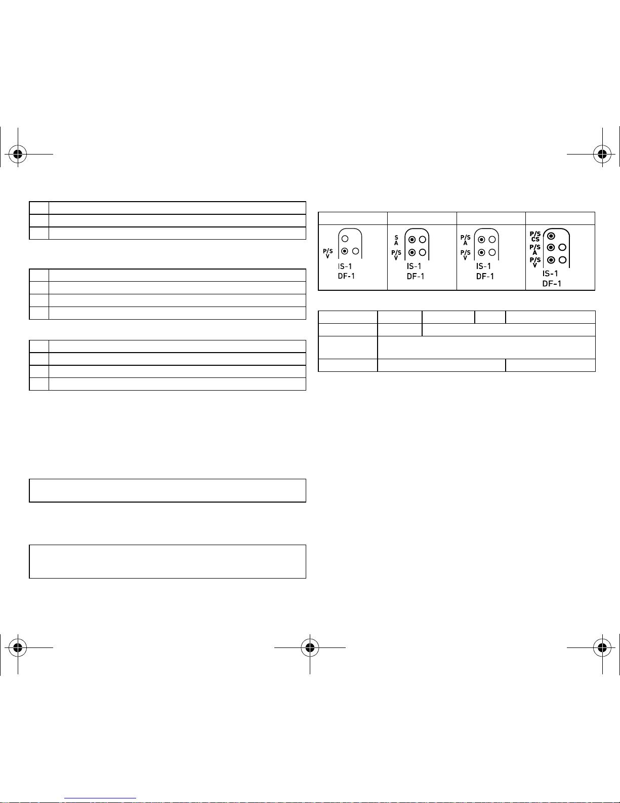
Device/ICD lead connection scheme
BIOTRONIK ICDs are designed for connection to ICD leads with a bipolar IS-1 connection (pacing/sensing) and DF-1 connection for shock coils.
Connection schemes of the device types:
Device and lead connections:
Possible technical failures
In principle, technical failures in the device due to component failures cannot be ruled
out; they occur, however, very rarely. Possible causes of such malfunctions include the
following:
•
Battery depletion
•
Lead dislodgment
•
Lead fracture
•
Insulation defects
Programmer
The portable programmer is used to transfer the current device program to the device.
In addition to this, the programmer is used for interrogation and storage of data from
the device. The programmer acts as an ECG and IEGM monitor with Miniclinic.
The programmer communicates with the device via the programming head. It has a TFT
touch screen with a color display, on which the ECG, IEGM, marker and functions are
shown simultaneously.
The programmer has, among others, the following functions:
•
Perform all tests during in-office follow-up
•
Display and print real-time and saved IEGMs with annotated markers
•
Determine the pacing threshold
V Shock in the ventricle
V Antitachycardia pacing (ATP) in the ventricle
E Detection via IEGM analysis
D Pacing in both chambers
D Sensing in both chambers
D Pulse inhibition and pulse triggering
R Rate adaptation
VVentricular pacing
V Sensing in the ventricle
I Pulse inhibition in the ventricle
R Rate adaptation
Note:
Device and lead have to match; Kentrox A+ Steroid and Linox Smart DX leads
match the Lumax 540 VR-T DX.
Note:
A bipolar as well as a unipolar coronary sinus lead can be connected to the left
ventricular CS connection of the Lumax HF variant. Several pacing polarities can be
set with a bipolar CS lead.
VR-T VR-T DX DR-T HF-T
VR-T VR-T DX DR-T HF-T
Atrium — IS-1 bipolar
Right ventricle IS-1 bipolar
2 x DF-1 unipolar
Left ventricle — IS-1 unipolar or bipolar
RV
SVC
SVC
RV
SVC
RV
RV
SVC
387158--G_GA_Lumax540_mul.book Page 3 Friday, February 1, 2013 5:38 PM
Page 5

4
BIOTRONIK Home Monitoring
®
In addition to effective pacing therapy, BIOTRONIK provides a complete therapy
management system:
•
With Home Monitoring, diagnostic and therapeutic information and technical data
are automatically sent to a stationary or mobile transmitter via an antenna in the
device header. The data are encrypted and sent from the transmitter to the
BIOTRONIK Service Center via the cellular phone network.
•
The received data are deciphered and evaluated. Each physician can set the criteria
for evaluation to be used for each patient and can configure the time of notification
via E-mail, SMS or fax.
•
A clear overview of the analysis results is displayed for the attending physicians on
the protected Internet platform HMSC (Home Monitoring Service Center).
•
Data transmission from the device is performed with a daily device message.
•
Device messages, which indicate special events in the patient's heart or in the
device, are forwarded immediately.
Technical manuals
The following technical manuals provide information about usage of the device system:
•
Technical manual for the device
•
Technical manual for the HMSC
•
Technical manual for the programmer
•
User manual for the device program:
—
As a help function in the user interface
—
As a file on CD
•
Technical manual for the leads
•
Technical manual for cables, adapters and accessories
Therapeutic and Diagnostic Functions
Overview
Depending on the type, the device program contains not only the ICD functions but also
all PM functions for 1, 2, or 3 chambers. The patient's heart rhythm is continuously
monitored; each arrhythmia is classified according to the heart rate and the adjustable
detection criteria. Depending on the preset values, antibradycardia as well as antitachycardia therapy is inhibited or delivered.
Antitachycardia pacing
The ICD can treat ventricular tachycardia with antitachycardia pacing (ATP); ATP can
also be delivered in the VF zone (ATP One Shot) when the rate stability indicates that
this will be effective before shock delivery (monomorphic rapid VTs).
Cardioversion, defibrillation
The ICD can treat ventricular tachyarrhythmia with cardioversion and/or defibrillation.
Shock polarity and energy can be programmed for individual therapies. Shock energies
between 1.0 and 40 J are possible. Before delivery of the first shock, the ICD can verify
that the tachyarrhythmia is still ongoing; in this verification mode the device can identify spontaneous conversion of the tachyarrhythmia and cancel shock delivery.
•
The shock paths can be set between the different shock coils (SVC/RV) and/or the
housing.
Home Monitoring: Message retrieval
The device sends information to the service center in two ways; automatically once a
day, and when triggered by certain events. All data can be viewed on the Internet subsequently.
•
IEGM-Online HD® with 3 channels in high resolution (High Density) with annotated
markers
•
Direct information on sustained atrial arrhythmia including IEGM Online HD
•
Regular IEGM recordings of the intrinsic rhythm for remote diagnosis
•
Daily transmission of atrial heart rate variability (SDANN)
Transmission of the following data:
•
Device settings
•
Impedance measurement values
•
Sensing measurement values
•
30-second IEGM recording
•
Statistics
Transmission is carried out on a weekly or monthly basis.
Antibradycardia pacing
Innovative rate hystereses, automatic sensor functions, and a night program promote
the patient's intrinsic rhythm, avoid overdrive pacing, and facilitate adaptation of the
device to the individual needs of the patient.
Positive AV hysteresis functions support the intrinsic conduction and thus the natural
contraction sequence. Negative AV hysteresis functions support the cardiac resynchronization therapy by maintaining pacing in stress situations.
387158--G_GA_Lumax540_mul.book Page 4 Friday, February 1, 2013 5:38 PM
Page 6

en • English
5
•
For resynchronization of the ventricles, 3-chamber devices have functions for
multisite ventricular pacing with possible VV delays in either direction.
•
To ensure that no additional surgery is necessary in case of a left-sided increase of
pacing threshold or undesired phrenic nerve stimulation by the CS lead, different
pacing polarites can be set for the CS lead with a triple-chamber device.
•
Setting an upper pacing rate for the atrium prevents unspecific atrial pacing, thus
improving the termination of pacemaker-mediated tachycardia.
•
Automatic threshold monitoring (ATM) for the left and right ventricle
Diagnostic functions
The device can record several types of arrhythmia episodes and store them in the
Holter memory:
•
VT/VF therapy episodes
•
SVT episodes (requirement SMART)
•
VT monitoring zones
•
AT/AF monitoring zones
The device stores diagnostic data about arrhythmia episodes:
•
Detection counter and therapy counter
•
Temporal characteristics of the episode
•
Details on the last ATP and shock deliveries
•
Shock data
•
Therapy history
•
Triple-channel IEGMs including marker channels, up to 30 min
Comprehensive memory functions such as histograms, Holter, mode switching longand short-term trends and the activity reports facilitate the evaluation of both patient
and device status.
The follow-up assistant functions have been largely automated.
The shock impedance is measured in an automatic procedure involving below-threshold electrical pulses. This process is painless for the patient. The impedance values are
automatically measured 4 times a day. They are averaged and provided in a trend in the
device and via Home Monitoring.
Painless measurement of shock impedance can also be carried out manually with the
programmer.
•
Lumax 540 VR-T DX is new (DX stands for diagnostics): Only one lead is required for
improved detection of AT and AF even with a single-chamber device. This enables
sensing in the atrium and ventricle as well as AV-sequential pacing. The SMART
algorithm helps distinguish more clearly between SVT and VT. The IEGM is
recorded in both chambers.
Prior to Implantation
Indications
Lumax ICDs can treat life-threatening ventricular arrythmias with antitachycardia
stimulation and defibrillation.
Single- and dual-chamber ICD
Lumax single and dual chamber ICDs are indicated for patients with the following risk:
•
Sudden cardiac death caused by ventricular arrhythmias
Triple-chamber ICD
Lumax triple-chamber ICDs are indicated for patients with the following threats:
•
Sudden cardiac death caused by ventricular arrhythmias
•
Congestive heart failure with ventricular asynchrony
Lumax ICDs are also indicated for primary prophylaxis in congestive heart failure
patients.
Contraindications
Known contraindications:
•
Tachyarrhythmia caused by temporary or reversible irritation e.g. poisoning,
electrolyte imbalance, hypoxia, sepsis or acute myocardial infarction
•
Such frequent VT or VF that the therapies would cause an unacceptably rapid
depletion of the device batteries
•
VT with few or without clinically relevant symptoms
•
VT or VF treatable by surgery
•
Concomitant diseases that would substantially limit a positive prognosis
•
Accelerated idioventricular rhythm
Shipping and Storage
Information on the package
The storage package for the device comprises a folded cardboard box with a quality
control seal and a label.
•
Device name with serial number and PID number
•
Technical details
•
Details on sterility and use by date
•
Ambient conditions during shipping and storage
387158--G_GA_Lumax540_mul.book Page 5 Friday, February 1, 2013 5:38 PM
Page 7

6
Ambient conditions
5°C to 45°C
Storage location
•
Devices are not to be stored close to magnets or sources of electromagnetic interference.
Implantation
Sterility
Delivery
The device and the accessories have been gas sterilized. Sterility is guaranteed only if
the plastic container and quality control seal have not been damaged.
Sterile container
The device and accessories are packaged respectively in two separately sealed plastic
containers. The inner plastic container is also sterile on the outside so that it can be
transferred in a sterile state during implantation.
Preparing the Implantation
Having the required parts ready
•
Device with blind plug DF-1 and IS-1
•
BIOTRONIK ICD leads complying with the requirements of EC Directive 90/385/EEC,
and lead delivery set
•
BIOTRONIK programmer complying with the requirements of EC Directive 90/385/
EEC
—
ECG cable PK-222
—
2 PK-141 patient cables or 2 PK-67 patient cables, either with patient adapters
PA-2 or PA-4 for connection of the pacing and sensing leads (IS-1) to ICS (dual and triple-chamber devices)
—
1 PK-144 patient cable with patient adapter PA-3 for connection of shock coils
(DF-1) to the programmer
•
External multi-channel ECG recorder/monitor
•
External defibrillator and paddles or adhesive electrodes.
Unpacking the device
Proceed as follows:
Connecting ICD Leads
Precautionary measures
Note:
Ensure that sterile spare parts are available for all parts that are to be
implanted.
W
WARNING
Non-terminated ventricular arrhythmia
If the ICD does not deliver an adequate therapy, ventricular arrhythmia is not terminated.
•
Keep an external defibrillator ready.
W
WARNING
Inadequate therapy due to previously damaged device
If the unpacked device is dropped on a hard surface during handling, discontinue use
and return it to BIOTRONIK. Use a replacement device.
1 Peel off the sealing paper of the non-sterile outer plastic container at the
marked position in the direction indicated by the arrow.
The inner plastic container may not come into contact with persons who have not
sterilized their hands or gloves, nor with non-sterile instruments.
2 Take hold of the inner plastic container by the gripping tab and take it out the
outer plastic container.
3 Peel off the sealing paper of the sterile inner plastic container at the marked
position in the direction indicated by the arrow.
Note:
Use only adapters approved by BIOTRONIK for ICD leads with different connections. Should you have questions about the compatibility of other manufacturers' ICD
leads, please contact BIOTRONIK.
W
WARNING
Short circuit due to open lead connections
Open – and thus not electrolyte-proof – IS-1 or DF-1 connections may cause undesired current flows to the body and penetration of body fluid into the device.
•
Close unused DF-1 connections with the blind plug DF-1, unused IS-1 connections with the blind plug IS-1.
387158--G_GA_Lumax540_mul.book Page 6 Friday, February 1, 2013 5:38 PM
Page 8

en • English
7
Connecting the ICD lead connector to the device
Leads are connected to the device according to the diagram on the header. Proceed as
follows:
Setting the lead polarity manually
Due to the risk of an entrance/exit block, bipolar lead polarity (sensing/pacing) should
only be set if bipolar leads are implanted.
Implanting the ICD
Implantation site
In general the ICD is implanted subpectorally on the left depending on the lead
configuration as well as the anatomy of the patient.
ICD status prior to implantation
The ICD is shipped in a deactivated mode and can be connected and implanted in this
state.
W
WARNING
Far-field sensing or insufficient defibrillation
When shock coils and pace/sense electrodes are not spaced sufficiently apart or
positioned inappropriately, this can lead to far-field sensing or insufficient defibrillation:
•
The distance between two shock coils must be greater than 6 cm.
•
Pace and sense electrodes must not contact each other.
W
CAUTION
Damage to the header while handling the blind plug
For every connection there is a blind plug in the header; the provided set screws must
be carefully loosened or tightened.
•
Loosen set screws with the supplied screwdriver. Use BIOTRONIK screwdrivers
with torque control only!
•
Do not forcibly pull out the blind plug!
•
If lead repositioning is necessary, re-order sterile screwdrivers from BIOTRONIK.
W
WARNING
Malfunctioning of the therapy functions or triggering of tachycardia by older,
unused leads
If, upon replacing the device, predecessor leads are no longer used but left where
they are, then their connections have to be insulated so that there is no additional
uncontrolled current path to the heart.
1 Disconnect stylets and insertion aids from the lead connector.
2
•
Connect ventricle shock coil to RV.
•
Connect vena-cava shock coil or subcutaneous shock coil to SVC.
3
•
Connect the bipolar IS-1-lead connector atrium to A S or P/S A.
•
Connect the bipolar IS-1 lead connector ventricle to P/S V.
•
Connect the unipolar or the bipolar IS-1 lead connector of the CS lead
to P/S CS.
4 Push the lead connector into the header without bending the conductor until the
connector tip becomes visible behind the set screw block.
5 If the lead connector cannot be inserted completely, the set screw may be
protruding into the cavity of the set screw block.
Carefully loosen the set screw without completely unscrewing it, so that it does
not become tilted upon retightening.
6 Use the screwdriver to perpendicularly pierce through the slitting in the center
of the silicone plug until it reaches the set screw.
7 Turn the set screw clockwise until the torque control starts (you will hear a
clicking sound).
8 Carefully withdraw the screwdriver without retracting the set screw.
•
Bipolar IS-1 connectors: tighten both set screws!
•
When you withdraw the screwdriver, the silicone plug automatically seals
the lead connection safely.
W
CAUTION
Shipment mode active!
During shipment, the device has been set to shipment mode.
The shipment mode reduces the battery's energy consumption, which may increase
longevity. The shipment mode controls the charge time of automatic capacitor reformations.
The shipment mode must be deactivated before the conclusion of the implantation
procedure.
The shipment mode will be automatically deactivated
as soon as electrophysiolo-
gical tests (e.g. impedance measurement) have been performed.
387158--G_GA_Lumax540_mul.book Page 7 Friday, February 1, 2013 5:38 PM
Page 9

8
Notes on applying a programming head (PGH)
The programming head (PGH) features a diagram of the device to assist in positioning
the head.
•
Make sure the PGH is positioned correctly to ensure proper telemetry.
Notes on applying a permanent magnet
Applying a permanent magnet interrupts sensing and therapy of tachycardia events.
After 8 hours of this type of deactivation, the device automatically activates the therapy
functions again to prevent unintentional permanent deactivation.
•
If detection interruptions of longer than 8 hours are required, the magnet has to be
briefly removed from the device. The 8 hour countdown restarts when the magnet
is applied again.
•
Use BIOTRONIK accessories, permanent magnets of type M-50 or programming
head PGH with magnet.
Sequence
Proceed as follows:
Activating the ICD
Proceed as follows:
After Implantation
Follow-up
Follow-up intervals
Follow-ups must be performed at regular, agreed intervals.
•
The first follow-up should be carried out by the physician using the programmer
(in-office follow-up) approximately 3 months after implantation following the lead
ingrowth phase.
•
The next in-office follow-up should be carried out once a year and no later than
12 months after the last in-office follow-up.
W
WARNING
Unintentional shock delivery
A shock could be delivered when handling an activated ICD.
•
If an already activated ICD is to be implanted: turn off ICD therapy.
W
WARNING
Interference of heart rate monitoring
Radio frequency as during electrocautery can interfere with electromyografic monitoring, e.g. be interpreted as arrhythmia and trigger a shock.
•
Turn off the detection function of the ICD during cauterization; the pacemaker
function can remain active.
•
Additionally check the peripheral pulse of the patient.
1 Shape the device pocket and prepare the vein.
2 Implant the ICD leads and perform measurements.
3 Connect the device and ICD leads.
4 Insert the device.
5 Check the device with standard tests.
6 Close the device pocket.
W
WARNING
Telemetry interference with inadequate pulse amplitude
If the pulse amplitude of the temporary program is not effective, the patient may get
into a hemodynamically critical condition. Telemetry interference can prevent correction of the critical amplitude.
•
Lift the programming head 30 cm; the device switches automatically to the
permanent program.
W
WARNING
Loss of pacing during exclusively left ventricular pacing
When only LV pacing is set and lead displacement occurs, the following dangers exist:
loss of ventricular pacing and the ATP therapy as well as induction of atrial arrhythmia.
•
Carefully check the pacing parameters.
1 Select the device program for Lumax on the programmer.
W
WARNING
No ICD therapy as delivered
At the time of delivery, the device is programmed with the factory settings.
2 Activate ICD therapy.
387158--G_GA_Lumax540_mul.book Page 8 Friday, February 1, 2013 5:38 PM
Page 10

en • English
9
Follow-up with BIOTRONIK Home Monitoring®
Monitoring using the Home Monitoring function does not serve to replace regular
in-office appointments with the physician required for other medical reasons.
Follow-up supported by Home Monitoring can be used to functionally replace in-office
follow-up under the following conditions:
•
The patient was informed that the physician must be contacted if symptoms worsen
or if new symptoms arise despite use of the Home Monitoring function.
•
Device messages are transmitted regularly.
•
The physician decides whether the data transmitted via Home Monitoring with
regard to the patient's clinical condition as well as the technical state of the device
system are sufficient. If not, an in-office follow-up has to be carried out.
Possible early detection due to information gained via Home Monitoring may necessitate an additional in-office follow-up. For example, the data may indicate at an early
stage lead problems or a foreseeable end of service time (ERI). Furthermore the data
could provide indications of previously unrecognized arrhythmias or modification of the
therapy by reprogramming the device.
Follow-up with the programmer
Use the following procedure for in-office follow-up:
Note for physicians
Use the patient ID card to obtain information on magnet behavior and tachyarrhythmia
detection.
Notes for patients
A patient brochure and a patient ID card are supplied with the device.
•
Provide the patient with the patient brochure and patient ID card.
•
Draw the patient's attention to prohibitory signs:
places with prohibitory signs must be avoided.
Replacement Indication
Foreword
The battery level can be continuously monitored with Home Monitoring and checked
during follow-ups.
Possible battery levels
•
BOL: Beginning of Life (i.e. BOS: Beginning of Service): 70% charge
•
MOL 1: Middle of Life : 70% to 40% residual charge
•
MOL 2: Middle of Life : 40% residual charge
•
ERI: Elective Replacement Indication, (i.e. RRT: Recommended Replacement Time)
•
EOS: End of Service
ERI
The device can monitor the cardiac rhythm for at least 3 months and deliver at least six
maximum energy shocks until EOS.
The selected parameters in the device program do not change.
1 Record and evaluate the external ECG.
2 Check the sensing and pacing functions.
3 Interrogate the device.
4 Evaluate the status and automatically measured follow-up data.
5 Possibly evaluate statistics and Holter/IEGM recording.
6 Manually perform standard tests if necessary.
7 Possibly customize program functions and parameters.
8 Transmit the program permanently to the device.
9 Print and document follow-up data (print report).
10 Finish the follow-up for this patient.
W
WARNING
Possible loss of left ventricular pacing if the pacing threshold has been determined
exclusively by ATM
The pacing threshold determined by ATM should not be used directly to determine the
left ventricular pacing amplitude (LV). The effectiveness of the LV pacing amplitude
has to be confirmed.
W
CAUTION
Temporally limited therapy
When the ERI display is noticed for the first time during a follow-up, the remaining
service time can be much less than 3 months even if follow-ups have been performed
at three month intervals.
387158--G_GA_Lumax540_mul.book Page 9 Friday, February 1, 2013 5:38 PM
Page 11

10
Action on ERI
Proceed as follows:
EOS
•
End of Service can be detected by Home Monitoring.
•
VT and VF detection and all therapies are deactivated.
•
The antibradycardia function remains active in the VVI mode:
—
Basic rate 50 ppm
—
Without special pacemaker functions, such as hysteresis, etc.
—
Amplitude of 6 V
—
Pulse width of 1.5 ms
Action on EOS
Proceed as follows:
Explantation and Disposal
Explanting the ICD
Proceed as follows:
Disposing of the ICD
Proceed as follows:
Cautionary Notes
Medical Complications
General information on possible complications
It is impossible to guarantee the efficacy of antitachycardia or fibrillation therapy, even
if these therapies have proved successful during intraoperative tests or subsequent
electrophysiological tests. In rare circumstances, the set therapies may prove ineffective or, in unfavorable conditions, even life-threatening. It is possible for therapies to
induce or accelerate tachycardia and cause sustained ventricular flutter or fibrillation.
Known possible complications:
The following are some of the known medical complications related to pacemaker
therapy and ICD therapy:
•
Formation of necrotic tissue
•
Vascular damage
•
Thrombosis
1 Replace device soon.
W
WARNING
EOS before explantation
If EOS occurs before replacement of the device, the patient is without antiarrhythmic
therapy and thus at risk of a life threatening condition!
1 Replace device immediately.
2 Monitor patient constantly until immediate replacement of the device!
Note:
Before the cremation of a deceased patient, the device must be explanted.
W
WARNING
Unintentional shock delivery
A shock could be delivered when handling an activated ICD. Devices may not be
explanted when detection is activated.
•
Turn off the detection function before explantation.
•
Do not simply cut the ICD leads.
1 Interrogate the device status.
2 Deactivate VT and VF therapies.
3 Disconnect the leads from the header.
4 Remove the device and leads using state-of-the-art technology.
5 Dispose of the device in an environmentally safe manner.
6 Fill out explantation form and send to BIOTRONIK.
Note:
Normal oxidation processes may cause ICD housing discolorations. This is
neither a device defect nor does it influence device functionality.
1 Clean the explant with an at least 1% sodium-hyperchlorine solution.
2 Rinse off with water.
3 Send to BIOTRONIK for disposal in an environmentally safe manner.
387158--G_GA_Lumax540_mul.book Page 10 Friday, February 1, 2013 5:38 PM
Page 12

en • English
11
•
Embolism
•
Increase in pacing threshold
•
Detection failures
•
Foreign body rejection
•
Cardiac tamponade
•
Muscle or nerve stimulation
•
Device-induced arrhythmias
•
Perforation of device pockets
•
Infections
•
Psychological intolerance or psychological dependency
Actions to prevent device-induced complications
Skeletal myopotentials
Bipolar sensing and control of sensitivity are adapted by the device to the rate spectrum
of intrinsic events so that skeletal myopotenials are usually not detected. Skeletal myopotentials can very rarely be sensed as intrinsic events and, depending on the interference pattern, may provoke inhibition or antiarrhythmia therapy.
Risky Therapeutic and Diagnostic Procedures
External defibrillation
The device is protected against the energy that is normally induced by external defibrillation. Nevertheless, any implanted device may be damaged by external defibrillation.
Specifically, the current induced in the implanted leads may result in necrotic tissue
formation close to the electrode/tissue interface. As a result, sensing properties and
pacing thresholds may change.
Due to possible damage to the patient or the device, the use of the following procedures
is contraindicated:
•
Therapeutic ultrasound and diathermy
—
Damage to the patient via excess warming of body tissue near the device
system
•
Radiation therapy
—
Shield the device sufficiently against radiation.
—
Check the system for integrity after applying radiation.
—
Radiation can cause latent damage.
•
Transcutaneous Electrical Nerve Stimulation (TENS)
•
Lithotripsy
•
Magnetic resonance imaging and the associated magnetic flux density
—
Damage or destruction of the device system due to strong magnetic interaction
—
Damage to the patient via excess warming of body tissue near the device
system
•
Electrocautery and high-frequency surgery
—
Damage to the patient via the induction of arrhythmia or ventricular fibrillation
•
Hyperbaric oxygen therapy
•
Applied pressures higher than normal pressure
W
CAUTION
Transmission of atrial tachycardia to the ventricle
Set the following parameters to avoid unphysiological pacing in the ventricle in cases
of high atrial rates or sinus tachycardia:
•
Activate Mode Switching for indicated patients.
•
Set the upper rate and the refractory periods to prevent abrupt ventricular rate
switching.
•
Prefer Wenckebach response and avoid 2:1 behavior.
Set all parameters to prevent constant switching between atrial and ventricle controlled modes to prevent unphysiological rhythm switching upon loss of AV sequential
pacing.
W
CAUTION
Pacemaker-mediated tachycardia in cases of retrograde conduction
Pacemaker-mediated tachycardia can occur in patients with retrograde conduction.
•
Measure the retrograde conduction time.
•
Switch on PMT protection to prevent pacemaker-mediated tachycardia.
•
Set the VA criterion.
Note:
Place adhesive electrodes anterior-posterior or perpendicular to the axis
formed by the device to the heart at least 10 cm away from the device and from
implanted leads.
W
CAUTION
Interference with the device and risk to the patient due to electrical current during
medical treatment
If electrical current from an external source is conducted through the body for diagnostic or therapeutic purposes, then the device has to be switched off or carefully
monitored during the initial treatment phases.
387158--G_GA_Lumax540_mul.book Page 11 Friday, February 1, 2013 5:38 PM
Page 13

12
Possible Technical Complications
•
Device component failures
•
Battery depletion
•
Lead dislocation
•
Lead fracture
•
Insulation defect
Possible Interference
Possible impairments due to EMI
All devices (PM/ICD) are susceptible to interference. The signals generated by sources
of interference could be interpreted as heart activity by the device, and/or could disturb
measurements required for adapting the rate of the device:
•
Depending on the pacing mode and the type of interference, these sources of interference may lead to pacemaker pulse inhibition or triggering, an increase in the
sensor-dependent pacing rate, or a fixed-rate pulse delivery.
•
Under unfavorable conditions, for example during diagnostic or therapeutic procedures, the interference sources may induce such a high level of energy into the
artificial pacing system that the device and/or cardiac tissue around the lead tip is
damaged.
•
BIOTRONIK devices have been designed so that their susceptibility to EMI is minimized.
•
However, due to the variety and intensity of EMI, absolute safety is not possible. It is
generally assumed that EMI produces only minor symptoms, if any, in patients.
Static magnetic fields
Above a flux density of 1.8 mT, the Reed contact in the ICD closes; the ICD therapy is
then deactivated. If the magnetic field decreases to below 1 mT, the Reed contact opens
and the ICD therapy is active again.
Possible sources of interference
Interference can be caused by:
•
Household appliances
•
Safety locks or anti-theft installations
•
Strong electromagnetic fields
•
Cellular phones and transmitters (CardioMessenger)
—
Patients are advised to hold cellular phones to the ear opposite the side on
which the device is implanted. Furthermore the cellular phone or transmitter
should be held at least 15 cm away.
—
Cellular phones and transmitters emit signals when in stand-by mode, i.e.
when not in use. Therefore these devices should not be carried in a breast
pocket or within a radius of 15 cm around the implanted device.
—
Electromagnetic interference only has a temporary effect. Implanted devices
function again properly when the cellular phone or transmitter is moved away.
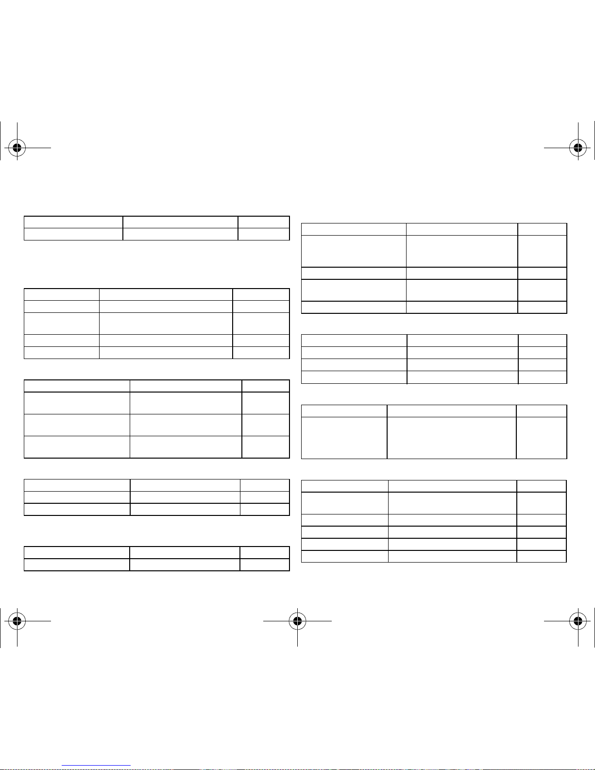
Technical Data
Bradycardia Therapy Parameters
Pacing Modes
Lumax 540 family
The following pacing modes are available:
W
CAUTION
Technical failures due to damaged leads
Switch the automatic impedance measurement function on to detect lead errors.
Impedance values that indicate a loss of lead integrity are documented in the event
list.
Note:
Indicate the possibility of interference to your patient if this is expected to have
a clinically relevant impact. Protect the device against the interference itself or its
effect by means of appropriate programming.
Device type Pacing modes Standard
DR-T;
HF-T
DDD, DDDR,
DDI, DDIR,
VDD, VDDR,
VDI, VDIR,
VVI, VVIR,
AAI, AAIR,
OFF
DDD
387158--G_GA_Lumax540_mul.book Page 12 Friday, February 1, 2013 5:38 PM
Page 14

en • English
13
Timing Parameters Lumax DR-T
Basic rate day/night
Rate hystereses
AV delay
AV hystereses
IRSplus
Post-ventricular atrial refractory period
VR-T VVI, VVIR,
OFF
VVI
VR-T DX VDD, VDDR,
VDI, VDIR,
VVI, VVIR
OFF
VVI
Parameter Range of values Standard
Basic rate 30 ... (5) ... 100 ... (10) ... 160 ppm 60 ppm
Night rate OFF
30 ... (5) ... 100 ppm
OFF
Night begins 00:00 ... (1 min) ... 23:59 hh:mm 22:00:00 hh:m
m
Night ends 00:00 ... (1 min) ... 23:59 hh:mm 06:00 hh:mm
Parameter Range of values Standard
Rate hysteresis OFF
-5 ... (-5) ... -90 ppm
OFF
Repetitive hysteresis OFF
1 ... (1) ... 15
OFF
Scan hysteresis OFF
1 ... (1) ... 15
OFF
Parameter Range of values Standard
AV delay Low; medium; high; fixed; individual Low
AV delay 1
at rate 1
15 (fixed); 40 ... (5) ... 350 ms
30 ... (10) ... 150 ppm
–
60 ppm
Device type Pacing modes Standard
AV delay 2
at rate 2
40 ... (5) ... 350 ms
40 ... (10) ... 160 ppm
–
130 ppm
Sense compensation OFF
-5 ... (5) ... -60 ms
-30 ms
Safety window 100 ms 100 ms
Parameter Range of values Standard
AV hysteresis mode OFF
Positive; Negative; IRSplus (only for
DR devices)
OFF
AV hysteresis 10 ... (10) ... 150 ms 50 ms
Positive repetitive AV hysteresis OFF
1 ... (1) ... 10
OFF
Negative repetitive AV hysteresis OFF
1 ... (1) ... 15 ... (5) ... 100 ... (10) ... 180
OFF
AV scan hysteresis OFF
1 ... (1) ... 10 ms
OFF
Parameter Range of values Standard
IRSplus OFF; ON OFF
AV hysteresis at IRSplus 400 ms 400 ms
Repetitive AV hysteresis at IRSplus OFF
1 ... (1) ... 10
5
AV scan hysteresis at IRSplus OFF
1 ... (1) ... 10
5
Parameter Range of values Standard
PVARP AUTO
175 ... (25) ... 600 ms
250 ms
Parameter Range of values Standard
387158--G_GA_Lumax540_mul.book Page 13 Friday, February 1, 2013 5:38 PM
Page 15

14
PVC classification; PVC lock-in protection
Upper rate (UTR)
Mode switching
Post Mode Switching Response (PMSR)
PMT protection
Pulse amplitude and pulse width
Automatic threshold monitoring
Automatic threshold monitoring (ATM)
Timing Parameters Lumax 540 VR-T DX
Basic rate day/night
Rate hystereses
PVARP after PVC PVARP + 225 ms (max: 600 ms) is
automatically programmed
475 ms
Parameter Range of values Standard
PVC discrimination after A
s
250 ... (50) ... 450 ms 350 ms
Parameter Range of values Standard
Upper rate 90 ... (10) ... 160 ppm 130 ppm
Atrial upper rate OFF
240 ppm
240 ppm
Parameter Range of values Standard
Intervention rate OFF
100 ... (10) ... 250 ppm
160 ppm
Onset criterion X 3 ... (1) ... 8 5
Resolution criterion Y 3 ... (1) ... 8 5
Mode DDI; DDI(R) when permanent DDD(R)
VDI, VDI(R) when permanent VDD(R)
DDI
VDI
Parameter Range of values Standard
Post mode switching rate OFF
+5 ... (5) ... +50 ppm
+10 ppm
Post mode switching duration 1 ... (1) ... 30 min 1 min
Parameter Range of values Standard
PMT detection/termination OFF; ON ON
VA criterion 250 ... (10) ... 500 ms 350 ms
Parameter Range of values Standard
Parameter Range of values Standard
Pulse amplitude A 0.2 ... (0.1) ... 6.2; 7.5 V 2.8 V
Pulse width A 0.4; 0.5; 0.7; 1.0; 1.2; 1.5 ms 0.4 ms
Pulse amplitude RV 0.2 ... (0.1) ... 6.2; 7.5 V 2.8 V
Pulse width RV 0.4; 0.5; 0.7; 1.0; 1.2; 1.5 ms 0.4 ms
Parameter Range of values Standard
ATM RV ON; OFF ON
Parameter Range of values Standard
Basic rate 30 ... (5) ... 100 ... (10) ... 160 ppm 60 ppm
Night rate OFF
30 ... (5) ... 100 ppm
OFF
Begin of night 00:00 ... (1 min) ... 23:59 hh:mm 22:00 hh:mm
Night ends 00:00 ... (1 min) ... 23:59 hh:mm 06:00 hh:mm
Parameter Range of values Standard
Rate hysteresis OFF
-5 ... (-5) ... -90 ppm
OFF
Repetitive hysteresis OFF
1 ... (1) ... 15
OFF
Scan hysteresis OFF
1 ... (1) ... 15
OFF
387158--G_GA_Lumax540_mul.book Page 14 Friday, February 1, 2013 5:38 PM
Page 16

en • English
15
AV delay
AV hystereses
IRSplus
Post-ventricular atrial refractory period
PVC classification; PVC lock-in protection
Upper rate (UTR)
Mode switching
Post Mode Switching Response (PMSR)
PMT protection
Pulse amplitude and pulse width
Parameter Range of values Standard
AV delay Low; Medium; High; Fixed; Individual Low
AV delay 1
at rate 1
15 (fixed); 40 ... (5) ... 350 ms
30 ... (10) ... 150 ppm
–
60 ppm
AV delay 2
at rate 2
40 ... (5) ... 350 ms
40 ... (10) ... 160 ppm
–
130 ppm
Parameter Range of values Standard
AV hysteresis mode OFF
Positive; Negative; IRSplus
OFF
AV hysteresis 10 ... (10) ... 150 ms 50 ms
Positive repetitive
AV hysteresis
OFF
1 ... (1) ... 10
OFF
Negative repetitive
AV hysteresis
OFF
1 ... (1) ... 15 ... (5) ... 100 ... (10) ... 180
OFF
AV scan hysteresis OFF
1 ... (1) ... 10
OFF
Parameter Range of values Standard
IRSplus OFF; ON OFF
AV hysteresis at IRSplus 400 ms 400 ms
Repetitive AV hysteresis at IRSplus OFF
1 ... (1) ... 10
5
AV scan hysteresis at IRSplus OFF
1 ... (1) ... 10
5
Parameter Range of values Standard
PVARP AUTO; 175 ... (25) ... 600 ms 250 ms
PVARP after PVC PVARP + 225 ms (max: 600 ms) is
automatically programmed
475 ms
Parameter Range of values Standard
PVC discrimination after A
s
250 ... (50) ... 450 ms 350 ms
Parameter Range of values Standard
Upper rate 90 ... (10) ... 160 ppm 130 ppm
Atrial upper rate OFF
240 ppm
240 ppm
Parameter Range of values Standard
Intervention rate OFF
100 ... (10) ... 250 ppm
160 ppm
Activation criterion X 3 ... (1) ... 8 5
Deactivation criterion Y 3 ... (1) ... 8 5
Mode VDI, VDI(R) when permanent VDD(R) VDI
Parameter Range of values Standard
Post mode switching rate OFF
+5 ... (5) ... +50 ppm
+ 10 ppm
Post mode switching duration 1 ... (1) ... 30 min 1 min
Parameter Range of values Standard
PMT detection/termination OFF; ON ON
VA criterion 250 ... (10) ... 500 ms 350 ms
Parameter Range of values Standard
Pulse amplitude RV 0.2 ... (0.1) ... 6.2; 7.5 V 2.8 V
Pulse width RV 0.4; 0.5; 0.7; 1.0; 1.2; 1.5 ms 0.4 ms
387158--G_GA_Lumax540_mul.book Page 15 Friday, February 1, 2013 5:38 PM
Page 17
16
Automatic threshold monitoring
Automatic threshold monitoring (ATM)
Timing Parameters Lumax VR-T
Basic rate day/night
Rate hysteresis
Pulse amplitude and pulse width
Automatic threshold monitoring
Automatic threshold monitoring (ATM)
Timing Parameters Lumax HF-T
Ventricular pacing
VV delay after Vp
Pacing polarity
Mode switching
Parameter Range of values Standard
ATM RV ON; OFF ON
Parameter Range of values Standard
Basic rate 30 ... (5) ... 100 ... (10) ... 160 ppm 60 ppm
Night rate OFF
30 ... (5) ... 100 ppm
OFF
Begin of night 00:00 ... (1 min) ... 23:59 hh:mm 22:00 hh:mm
End of night 00:00 ... (1 min) ... 23:59 hh:mm 06:00 hh:mm
Parameter Range of values Standard
Rate hysteresis OFF
-5 ... (-5) ... -90 ppm
OFF
Repetitive hysteresis OFF
1 ... (1) ... 15
OFF
Scan hysteresis OFF
1 ... (1) ... 15
OFF
Parameter Range of values Standard
Pulse amplitude V 0.2 ... (0.1) ... 6.2; 7.5 V 2.8 V
Pulse width V 0.4; 0.5; 0.7; 1.0; 1.2; 1.5 ms 0.5 ms
Parameter Range of values Standard
ATM RV ON; OFF OFF
Parameter Range of values Standard
Ventricular pacing RV, BiV for: DDD(R); DDI(R);
VDD(R); VDI(R);VVI(R)
LV for: DDD(R); VDD(R)
BiV
LV T-wave protection OFF; ON ON
Triggering OFF
RVs; RVs+RVES
RVs
Maximum trigger rate AUTO; 90 ... (10) ... 160 ppm AUTO
Parameter Range of values Standard
Initially paced chamber RV; LV LV
VV delay 0 ... (5) ... 100 ms 5 ms
VV delay after V
s
0 ms
Parameter Range of values Standard
Polarity pace LV LV tip/LV ring (bipolar 1)
LV tip/RV ring (common ring bipolar 2)
LV ring/LV tip (inverse bipolar 3)
LV ring/RV ring (ring-to-ring bipolar 4)
LV tip/LV ring
Parameter Range of values Standard
Intervention rate OFF
100 ... (10) ... 250 ppm
160 ppm
Activation criterion X 3 ... (1) ... 8 5
Deactivation criterion Y 3 ... (1) ... 8 5
Mode VDI; VDI(R) when permanent VDD(R) VDI
Ventricular pacing RV; BiV BiV
387158--G_GA_Lumax540_mul.book Page 16 Friday, February 1, 2013 5:38 PM
Page 18

en • English
17
Automatic threshold monitoring
Automatic threshold monitoring (ATM)
Rate Adaptation
Accelerometer
Tachyarrhythmia Therapy – Parameters
Sensing Parameters
Atrium
Lumax VR-T DX, DR-T; HF-T
Right ventricle
Lumax VR-T, VR-T DX, DR-T, HF-T
LV T-wave protection OFF; ON ON
Triggering OFF
RVs; RVs + PVC
RVs
Modification of basic rate OFF; +5 ... (5) ... +30 ppm +10 ppm
Parameter Range of values Standard
ATM RV ON; OFF ON
ATM LV ON; OFF ON
Parameter Range of values Standard
Maximum sensor
rate
AUTO
90 ... (5) ... 160 ppm
120 ppm
Sensor gain 1.0; 1.1; 1.3; 1.4; 1.6; 1.8; 2.0; 2.2; 2.6; 3.0; 3.3; 3.7;
4.0; 4.5; 5.0; 6.0; 7.0; 8.0; 9.0; 10; 11; 12; 14; 16; 18;
20; 22; 24; 28; 32; 35; 40
6.0
Automatic gain OFF; ON OFF
Sensor threshold•Very low = 0
•
Low = 3
•
Medium = 7
•
High = 11
•
Very high = 15
Medium
Rate increase 0.5; 1 ... (1) ... 6 ppm/cycle 2 ppm/cycle
Rate decrease 0.25 ...(0.25)... 1.25 ppm/cycle 0.5 ppm/cycle
Parameter Range of values Standard
Parameter Range Standard
Sensing
•
STD - standard
•
OFF - disabled
•
IND - individual change in
sensing details
STD
Minimum threshold 0.2 ... (0.1) ... 2.0 mV 0,4 mV
Far-field protection after Vp 50 ... (25) ... 225 ms 75 ms
Far-field protection after Vs OFF
25 ... (25) ... 225 ms
75 ms
Upper threshold DR, HF 50; 75; 87,5% 50%
Upper threshold DX 50; 75; 87,5% 75%
Lower threshold 12,5; 25; 50% 25%
Parameter Range Standard
Sensing RV
•
STD — standard
•
TWS — extended T-wave suppression
•
VFS — extended VF sensitivity
•
IND — individual change in
sensing details
STD
Minimum threshold 0.5 ... (0.1) ... 2.5 mV 0.8 mV
Blanking after atrial pacing 50 ... (10) ... 100 ms 50 ms
Upper threshold 50; 75; 87,5% 50%
Hold of upper threshold 100 ... (20) ... 600 ms 360 ms
Lower threshold 12,5; 25; 50% 25%
387158--G_GA_Lumax540_mul.book Page 17 Friday, February 1, 2013 5:38 PM
Page 19

18
Left ventricle
Lumax HF-T
Polarity sense
Lumax HF-T
Detection Parameters
Detection intervals
Detection counter
Onset
Stability
SMART detection
Sustained VT; without SMART, without SMART redetection
Blanking after RV pacing AUTO
100 ... (10) ... 350 ms
AUTO
Post pace T-wave suppression ON; OFF OFF
Parameter Range Standard
Sensing LV
•
STD - standard
•
OFF - disabled
•
IND - individual change in sensing
details
STD
Minimum threshold 0.5 ... (0.1) ... 2.5 mV 1,6 mV
Upper threshold 50; 75; 87.5% 50%
Hold of upper threshold 100 ... (20) ... 600 ms 360 ms
Lower threshold 12,5; 25; 50% 50%
Parameter Range Standard
LV polarity sense UNIP (LV tip/housing)
BIPL (LV tip/LV ring)
UNIP
Parameter Range Standard
Interval VT1 OFF
270 ... (10) ... 600 ms
OFF
Interval VT2 OFF
270 ... (10) ... 500 ms
OFF
Interval VF OFF
200 ... (10) ... 400 ms
300 ms
Parameter Range Standard
Parameter Range Standard
Detection counter VT1 10 ... (2) ... 60 26
Detection counter VT2 10 ... (2) ... 40 16
Detection counter VF - X 6 ... (1) ... 30 8
Detection counter VF - Y 8 ... (1) ... 31 12
Parameter Range Standard
Onset criterion in VT1/VT2
with SMART
20% 20%
Onset criterion in VT1/VT2
without SMART
OFF
4 ... (4) ... 32%
20%
Parameter Range Standard
Stability in VT1/VT2 with SMART 12% 12%
Stability in VT1/VT2
without SMART
OFF
8 ... (4) ... 48 ms
24 ms
Stability ATP One Shot 12% 12%
Parameter Range Standard
SMART detection VT1 OFF; ON ON
SMART detection VT2 OFF; ON ON
Parameter Range Standard
Sustained VT OFF
00:30; 01:00; 02:00; 03:00; 05:00; 10:00;
15:00; 20:00; 25:00; 30:00 [mm:ss]
OFF
387158--G_GA_Lumax540_mul.book Page 18 Friday, February 1, 2013 5:38 PM
Page 20

en • English
19
Forced termination; with SMART, SMART redetection
Redetection counter
Therapy Parameters
Ventricle
ATP parameters
ATP One Shot parameters; ATP in VF
Parameter Range Standard
Forced termination OFF 1 ... (1) ... 15 min 1 min
Parameter Range Standard
Redetection counter VT1 10 ... (2) ... 30 20
Redetection counter VT2 10 ... (2) ... 30 14
Parameter Range Standard
Energy of 1st shock and 2nd
shock VT1, VT2
OFF 1 ... (1) ... 16 ... (2) ... 40 J 40 J
Energy of 1st shock and 2nd
shock VF
1 ... (1) ... 16 ... (2) ... 40 J 40 J
Shock sequences 3rd-nth shock
in VT1
OFF
1*40 J; 2*40 J; 3*40 J; 4*40 J;
5*40 J; 6*40 J
6*40 J
Shock sequences 3rd-nth shock
in VF
OFF
4*40 J; 5*40 J; 6*40 J
6*40 J
Number of shocks
(VT1/VT2)
0 ... (1) ... 8 8
Number of shocks (VF) 2; 6 ... (1) ... 8 8
Confirmation in VT1, VT2, VF OFF; ON ON
Shock form in VT1, VT2, VF Biphasic; biphasic2 Biphasic
Polarity in VT1, VT2, VF Normal; inverse; alternating Normal
Shock path (valid for all shocks
including the painless shock
impedance)
RV SVC + housing
RV housing
RV SVC
RV SVC +
housing
Shock path DX RV housing
Parameter Range Standard
ATP type Burst; Ramp; Burst + PES Burst
ATP attempts OFF
1 ... (1) ... 10
3
Ventricular pacing
(HF devices only)
RV; LV; BiV RV
Number S1 1 ... (1) ... 10 5
Add. S1 OFF; ON ON
R-S1 interval 200 ... (10) ... 500 ms (absolute);
70 ... (5) ... 95% (adaptive)
80%
S1 decrement 5 ... (5) ... 40 ms 10 ms
Scan decrement OFF
5 ... (5) ... 40 ms
OFF
S1-S2 interval 200 ... (10) ... 500 ms (absolut);
70 ... (5) ... 95% (adaptive)
70%
Minimum ATP interval 200 ... (5) ... 300 ms 200 ms
ATP timeout OFF
00:15 ... (00:15) ... 05:00 mm:ss
OFF
ATP optimization OFF; ON OFF
ATP pulse amplitude 7.5 V 7.5 V
ATP pulse width 1.5 ms 1.5 ms
Parameter Range Standard
ATP type OFF;
Burst; Ramp; Burst + PES
OFF
ATP attempts 1 1
Ventricular pacing
(HF devices only)
RV; LV; BiV RV
Number S1 1 ... (1) ... 10 8
387158--G_GA_Lumax540_mul.book Page 19 Friday, February 1, 2013 5:38 PM
Page 21

20
Progressive course of therapy
Post-shock pacing
Diagnostics Functions
Home Monitoring, Holter Memory and Statistics
Home Monitoring
Holter episodes
Statistics
R-S1 interval 200 ... (10) ... 350 ms (absolute);
70 ... (5) ... 95% (adaptive)
85%
S1 decrement 5 ... (5) ... 40 ms 10 ms
S1-S2 interval 200 ... (10) ... 350 ms (absolute);
70 ... (5) ... 95% (adaptive)
70%
Stability 12% 12%
ATP pulse amplitude 7.5 V 7.5 V
ATP pulse width 1.5 ms 1.5 ms
Parameter Range Standard
Progressive course of therapy OFF; ON ON
Parameter Range Standard
Pacing mode
(automatically programmed)
•
DDI when permanent DDD(R),
DDI(R), AAI(R)
•
VDI when permanent VDD(R),
VDI(R)
•
VVI when permanent VVI(R);
•
OFF
Basic rate 30 ... (5) ... 100 ... (10) ... 160 ppm 60 ppm
Rate hysteresis OFF
-5 ... (-5) ... -65 ppm
OFF
AV delay 50 ... (10) ... 100 ... (10) ... 160 ms 140 ms
Ventricular pacing RV; BiV RV
LV T-wave protection OFF; ON ON
Triggering OFF
RVs; RVs + PVC.
OFF
Post-shock duration OFF
00:10 ... (00:10) ... 00:50; 01:00 ...
(01:00) ... 10:00 mm:ss
00:10 mm:ss
Parameter Range Standard
Parameter Range Standard
Home Monitoring OFF; ON OFF
Time of transmission 00:00 ... (1 min) ... 23:59 hh:mm 01:00 hh:mm
IEGM for therapy episodes OFF; ON OFF
IEGM for monitoring episodes OFF; ON OFF
Periodic IEGM OFF
2; 3; 4; 6 months
OFF
Sustained atrial episodes (DR, HF) OFF
0.5; 6; 12; 18 h
12 h
Thoracic impedance ON; OFF OFF
Parameter Range Standard
AT/AF OFF; ON ON
SVT OFF; ON ON
Parameter Range Standard
AT/AF rate 100 ... (10) ... 250 bpm 200 bpm
Start resting period 0:00 ... (10) ... 23:50 hh:mm 02:00 hh:mm
Resting period duration 0:00 ... (10) ... 23:50 hh:mm 04:00 hh:mm
Automatic impedance
measurement
VR, DX, DR: ON; OFF
HF: ON; OFF; LV OFF
ON
Thoracic impedance ON; OFF OFF
387158--G_GA_Lumax540_mul.book Page 20 Friday, February 1, 2013 5:38 PM
Page 22

en • English
21
Characteristics
Electrical Characteristics
Measuring conditions
If not indicated otherwise, all specifications refer to the following conditions:
•
Ambient temperature of 37ºC 2°C and 500 5% load (pacing/sensing) or
50 1% load (shock)
•
Software used: Programmer in standard program
Standards
The specifications are made according to EN 45502-2-2:2008.
Factory settings
All therapy parameters are deactivated at delivery.
Home Monitoring
Telemetry data
Atrial pacing pulse
Lumax DR-T; Lumax HF-T
Ventricular pacing pulse
Lumax VR-T; Lumax VR-T-DX; Lumax DR-T right ventricle; Lumax HF-T right and left
ventricle; except for polarity pace LV ring/ LV tip inverse bipolar
Lumax HF-T left ventricle; polarity pace LV ring/LV tip inverse bipolar
Arrhythmia classes VT1, VT2, VF Antibradycardia pacing Home Monitoring
OFF OFF OFF
Nominal carrier frequency Maximum power of transmission
403.62 MHz
25 W (-16 dBm)
387158--G_GA_Lumax540_mul.book Page 21 Friday, February 1, 2013 5:38 PM
Page 23

22
Resistance to interference
With unipolar sensing, the requirements of EN 45502-2-2:2008 are met for interference
voltages 0.6 mV (peak to peak).
EMC requirements relating to section 27.5 are met as long as atrial sensitivity is set to
1.0 mV (corresponds to factory settings) or higher ( 1.0 mV). Appropriate measures
must be taken to assure interference-free therapy if more sensitive values are chosen.
Common mode rejection
Indication of rate in Hz, of common mode rejection in dB:
ATP amplitude
Set parameters:
Results:
Sensitivity setting
Indication of minimum and maximum of automatic sensitivity setting; measurement of
the actual values with positive and negative polarity:
Rate Atrium Atrium V right V left
VR-T DX VR-T, DR-T, HF-T
CMRR (Common Mode Rejection Ratio)
16.667656464
50 80 80 67 64
60 81 75 66 63
Burst Value
Amplitude 7.5 V
Pulse width 1.5 ms
R-S1 interval 300 ms
Number S1 5
Load resistance 500
ATP amplitude Value with tolerance Measured minimum Measured maximum
RV
Mean value
7.5 V 1,5 V
—
7.42 V
5.18 V
7.50 V
5.18 V
LV
Mean value
7.5 V 1.5 V
—
7.50 V
5.18 V
7.50 V
5.18 V
BiV
Mean value
7.5 V 1.5 V
—
7.42 V
5.16 V
7.50 V
5.18 V
Note:
The programmed atrial sensitivity is intensified by a factor of 5 for
Lumax 540 VR-T DX.
Sensitivity Test signal wave
shape
Value Tolerance Measured
value
A: positive [mV]
sin2 15 ms
0.2 0.2 ... 0.5 0.26
Standard triangle — 0.41
A: negative [mV]
sin2 15 ms
0.2 0.2 ... 0.5 0.28
Standard triangle — 0.43
VR-T DX: A: positive
[mV]
sin2 15 ms
0.2 0.02 ... 0.10
(0.1 - 0.5)
0.08
Standard triangle — 0.08
VR-T DX:
A: negative [mV]
sin2 15 ms
0.2 0.02 ... 0.10
(0.1 - 0.5)
0.10
Standard triangle — 0.12
RV: positive [mV]
sin2 40 ms
0.5 0.3 ... 0.7 0,56
Standard triangle — 0.58
RV: negative [mV]
sin2 40 ms
0.5 0.3 ... 0.7 0.45
Standard triangle 0.58
LV: positive [mV]
sin2 40 ms
0.5 0.3 ... 0.7 0.64
Standard triangle 0.65
LV: negative [mV]
sin2 40 ms
0.5 0.3 ... 0.7 0.54
Standard triangle — 0.68
387158--G_GA_Lumax540_mul.book Page 22 Friday, February 1, 2013 5:38 PM
Page 24

en • English
23
Shock energies / peak voltages at: RV SVC + housing
Lumax 540 VR-T, VR-T DX, DR-T, HF-T as 40 J device with shock path:
RV SVC + housing
Shock energies / peak voltages at: RV SVC
Lumax 540 VR-T, VR-T DX, DR-T, HF-T as 40 J device with shock path: RV SVC
Behavior in case of EMI
In case of electromagnetic interference, the device switches into the V00 mode when
the interference rate is exceeded if VVI(R) or VDD(R) pacing mode was set previously, or
into the D00 pacing mode if DDI(R) or DDD(R) pacing mode was set previously.
Mechanical Characteristics
Housing
Materials in contact with body tissue
The following materials of the ICD system have contact with body tissue:
Radiopaque marker
The radiopaque marker is on the left, positioned vertically.
Shock energy set Measurement of shock energy at 50
1 J
E nominal 94% 25%
0.7 ... 1.18 J
E actual 0.81 J
Tolerance range: U max 90 ... 120 V
U max actual 101.01 V
20 J
E nominal 94% 10%
16.9 ... 20.9 J
E actual 17.31 J
Tolerance range: U max 440 ... 480 V
U max actual 465 V
40 J
E nominal 94% 10%
33.8 ... 41.4 J
E actual 35.31 J
Tolerance range: U max 630 ... 670 V
U max actual 656.7 V
Shock energy set Measurement of shock energy at 50
1 J
E nominal 94% 25%
0.7 ... 1.18 J
E actual 0.83 J
Tolerance range: U max 90 ... 120 V
U max actual 104.2 V
20 J
E nominal 94% 10%
16.9 ... 20.9 J
E actual 17.54 J
Tolerance range: U max 440 ... 480 V
U max actual 466.7 V
40 J
E nominal 94% 10%
33.8 ... 41.4 J
E actual 35.60 J
Tolerance range: U max 630 ... 670 V
U max actual 659.3 V
Device type W x H x D in mm Volume in ccm Mass g
VR-T, VR-T DX, DR-T 66 x 55 x 13 37.2 92
HF-T 66 x 59 x 13 39.8 94
Housing Header Sealing plugs, sealing lips
Titanium Epoxy resin Silopren
Manufacturing year Radiopaque marker
nn BIO SH
Shock energy set Measurement of shock energy at 50
387158--G_GA_Lumax540_mul.book Page 23 Friday, February 1, 2013 5:38 PM
Page 25

24
ICD leads
Connections
ICD lead configuration
Tolerances
The following tolerances apply to the programmable parameters:
Included Equipment Lumax
Standard
In the sterile container there is:
•
Device of the Lumax product family
•
Blind plug DF, mounted in the header
•
Blind plug IS-1, mounted in the header (only for HF devices)
•
Screwdriver
In the storage package there is:
•
Patient's ICD manual
•
Sterile cover for the PGH programming head of the programmer
•
Implantation protocol
•
Serial number label
•
Patient ID card
•
Follow-up report
•
Warranty card
•
Technical manual
Orders
The devices are available with the following order numbers (some device types are not
available in all countries):
Accessories
All accessories must correspond to the requirements of the EC Directive 90/385/EEC.
•
BIOTRONIK leads
•
BIOTRONIK programming and monitoring devices
•
Permanent magnet M-50
•
For Home Monitoring: BIOTRONIK transmitters
Pacing/sensing Shock
•
VR-T , VR-T DX: 1 x IS-1 bipolar
•
DR-T: 2 x IS-1 bipolar
•
HF-T: 3 x IS-1 bipolar
•
All device types: 2 x DF-1
Connection Lead connector
RV DF-1 connector of the ventricular shock coil
SVC DF-1 connector of the vena cava electrode
S A IS-1 connector of the atrial sense electrode, bipolar
P/S A IS-1 connector of the atrial pace/sense electrode, bipolar
P/S V IS-1 connector of the ventricular pace/sense electrode, bipolar
CS IS-1 connector of the ventricular pace/sense coronary sinus electrode,
bipolar or unipolar
Parameter Tolerance
Pacing pulse amplitudes +20% to -25%
Pacing pulse width
10%
Atrium sensitivity
DR-T, HF-T
For values 0,4 mV: 0.2 mV to 0.52 mV
For values 0.4 mV: +30% to -50%
Atrium sensitivity
VR-T DX
For values 0,4 mV:
–0.1 mV to +0.3 mV; for values 0.4 mV:
+30% to –60%
Sensitivity of right and left ventricle40%
Pacing intervals
20 ms
Escape interval
20 ms
Detection intervals
20 ms
Refractory periods
20 ms
ATP coupling interval
20 ms
Shock coupling interval
20 ms
Shock energy/charging voltage Electrical characteristics: see peak voltages
Device type Order number
540 VR-T 360348
540 VR-T DX 368852
540 DR-T 360346
540 HF-T 360347
Parameter Tolerance
387158--G_GA_Lumax540_mul.book Page 24 Friday, February 1, 2013 5:38 PM
Page 26

en • English
25
Service Life
Lumax Battery Data
Battery LiS R7
LITRONIK LiS 3192 R7:
Battery GB
GREATBATCH GB 2491:
Lumax Battery Charge Times
Lumax 540 VR-T
Lumax 540 VR-T DX
Lumax 540 DR-T
Lumax 540 HF-T
Lumax Service Times
Legend
Legend for the following service time graphics:
•
X axis: Number of maximum energy charging processes (shocks and capacitor
reforming)
•
Y axis: Longevity in years;
of Home Monitoring devices:
—
1 periodic message per day
—
12 IEGM transmissions per year
•
Maximum energy charging processes per year:
—
A = 4
—
B = 8
—
C = 12
—
D = 16
—
E = 20
Model LiS 3192 R7
Manufacturer LITRONIK GmbH & Co,
01796 Pirna, Germany
System LiMnO2
Usable capacity until EOS 1720 mAh
Battery voltage at BOL (BOS) 3.2 V
Battery ID number shown on the programmer 3
Model GB 2491
Manufacturer GREATBATCH, INC.
Clarence, NY 14031
System Li/SVO/CFx
Usable capacity until EOS 1720 mAh
Battery voltage at BOL (BOS) 3.2 V
Battery ID number shown on the programmer 1
Shock energy Battery type Order number Charge time
at BOL (BOS)
Charge time
at ERI
HE LiS 3192 R7 or
GB 2491
360348
10 s
12 s
Shock energy Battery type Order number Charge time
at BOL (BOS)
Charge time
at ERI
HE LiS 3192 R7 or
GB 2491
368852
10 s
12 s
Shock energy Battery type Order number Charge time
at BOL (BOS)
Charge time
at ERI
HE LiS 3192 R7 or
GB 2491
360346
10 s
12 s
Shock energy Battery type Order number Charge time
at BOL (BOS)
Charge time
at ERI
HE LiS 3192 R7 or
GB 2491
360347
10 s
12 s
387158--G_GA_Lumax540_mul.book Page 25 Friday, February 1, 2013 5:38 PM
Page 27

26
Calculation of service times
•
The service times are calculated with the following values:
—
Pulse amplitude: 2.8 V
—
Pulse width: 0.4 ms
—
Pacing impedance: 500
—
Basic rate: 60 ppm
•
Pacing site:
—
Triple-chamber devices: RV
—
Dual-chamber devices: RV and A
—
Triple-chamber devices: RV, LV and A
Lumax 540 VR-T
Service times with LiS 3192 R7 and GB 2491 battery
Lumax 540 VR-T DX
Service times with LiS 3192 R7 and GB 2491 battery
Note:
Devices in the Lumaxfamily should be implanted within 16 months between the
date of manufacture and the use by date as specified on the package.
•
If the ICD is implanted shortly before the use by date, the expected service time
may be reduced by up to 15 months.
•
Please note that four capacitor reformings are carried out per year. Therefore
you have to account for at least 4 shocks per year, even if less than 4 have been
delivered (see the following charts of service times).
387158--G_GA_Lumax540_mul.book Page 26 Friday, February 1, 2013 5:38 PM
Page 28
en • English
27
Lumax 540 DR-T
Service times with LiS 3192 R7 and GB 2491 battery
Lumax 540 HF-T
Service times with LiS 3192 R7 and GB 2491 battery
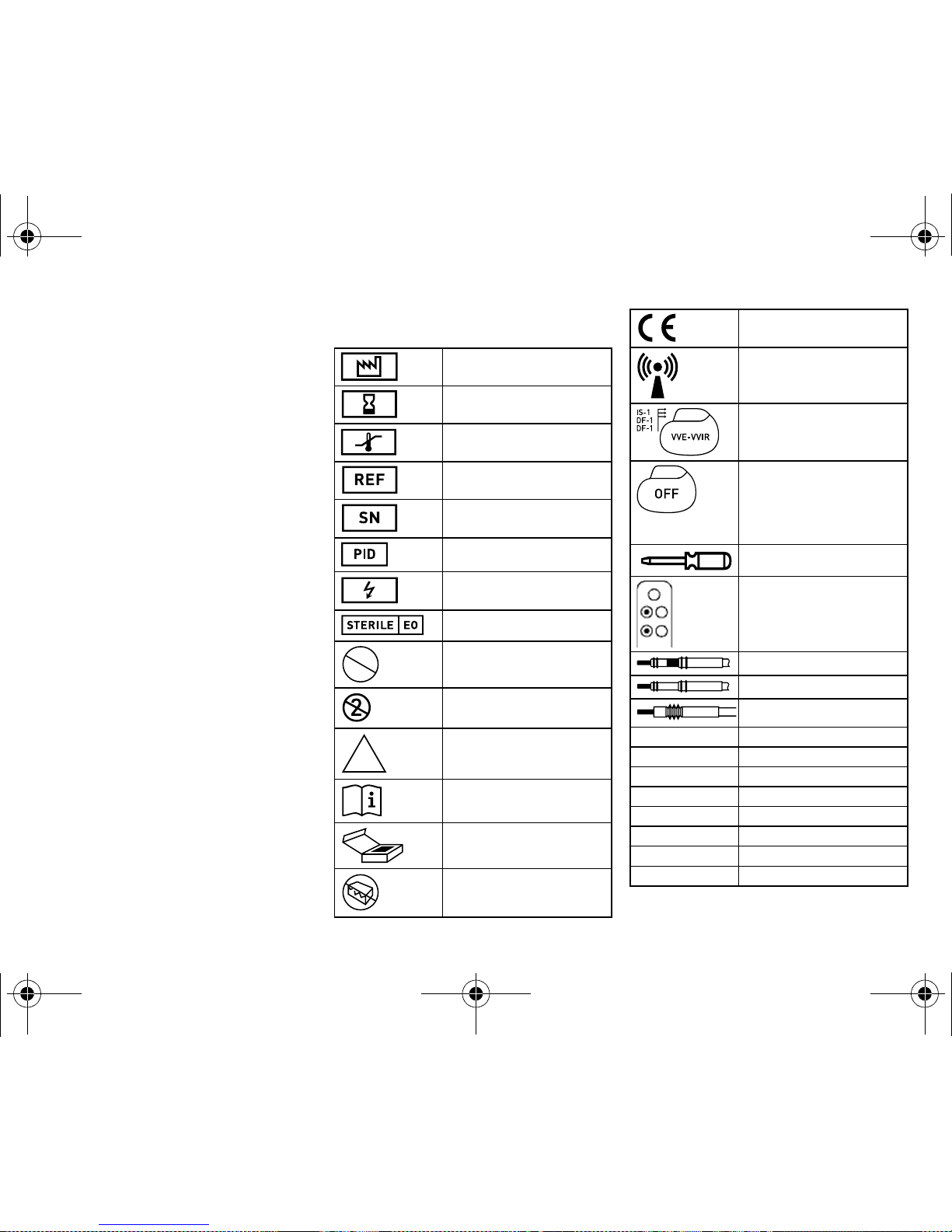
Legend for the Label
The label icons symbolize the following:
Manufacturing date
Use by
Storage temperature
BIOTRONIK order number
Serial number
Product identification number
Warning: dangerous voltages!
Sterilized with ethylene oxide
Do not resterilize!
Single use only. Do not reuse!
Non-sterile
Follow the instructions in the
technical manual!
Contents
Do not use if package is
damaged!
STERILIZE
2
NON
STERILE
CE mark
Transmitter with non-ionizing
radiation on specified frequency;
turned off during shipment
Device with NGB coding and
name of compatible ICD leads
(example)
Device with factory settings:
Bradycardia and tachycardia
therapies are set to OFF and/or
the program settings are physiologically ineffective
Screwdriver
Position of connector ports in
the header (example)
Bipolar IS-1 connector
Unipolar IS-1 connector
Unipolar DF-1 connector
A
Atrium
V
Ventricle
CS
Coronary sinus
Pace
Pacing
Sense
Sensing
Shock
Shock
RV
High-voltage connector port
SVC
High-voltage connector port
387158--G_GA_Lumax540_mul.book Page 27 Friday, February 1, 2013 5:38 PM
Page 29

28
cs • Česky
Popis systému
Zamýšlené lékařské použití
Lumax je název pro skupinu implantabilních kardioverter-defibrilátorů (ICD).
Primárním cílem léčby je prevence náhlé srdeční smrti. Cílem je automaticky detekovat
a ukončit srdeční zástavu vyvolanou komorovou tachyarytmií. Skupina Lumax zahrnuje
všechny hlavní terapeutické kardiologické a elektrofyziologické přístupy.
Zdravotnický prostředek je dále schopný léčit bradykardické arytmie a městnavé
srdeční selhání. Městnavé srdeční selhání se léčí pomocí srdeční resynchronizační
léčby prostřednictvím 'multisite' komorové stimulace známé jako srdeční
resynchronizační léčba (CRT).
Integrovaná funkce pro domácí monitorování (Home Monitoring) může poskytnout
informace o vyskytujících se poruchách rytmu a podaných léčbách ve skutečném čase
a rovněž pomocí IEGM-Online HD®. Jsou též zasílány statistické údaje o stavu pacienta
a rovněž informace o integritě samotného zdravotnického prostředku.
Implantace ICD je symptomatická léčba, která má následující cíle:
•
ukončení spontánní komorové fibrilace (VF) pomocí šoku;
•
ukončení spontánní komorové tachykardie (VT) pomocí antitachykardické stimulace
(ATP); v případě neúčinné ATP nebo hemodynamicky netolerované VT použitím
šoku;
•
srdeční resynchronizace pomocí 'multisite' komorové stimulace (3dutinový
implantát);
•
kompenzace bradykardie pomocí komorové (1dutinový implantát) nebo AV
sekvenční stimulace (2 a 3dutinový implantát).
Předpokládáné odborné znalosti
Mimo medicínského základu jsou třeba podrobné znalosti funkcí a podmínek použití
implantátového systému. Pouze lékařští odborníci s těmito zvláštními znalostmi mohou
implantáty používat v souladu s ustanovením. Nejsou-li tyto znalosti k dispozici, musí
být uživatel proškolen.
ICD systém
Lumax
ICD systém Lumax se skládá z následujících komponent:
•
1, 2 nebo 3dutinový implantát s konektory pro bipolární snímání a stimulaci
a rovněž s konektory pro šokovou léčbu;
•
ICD elektrody:
—
jedna bipolární ICD elektroda s jednou nebo dvěma impulzními cívkami pro
dutinu (1dutinový implantát),
—
jedna bipolární elektroda pro síň a jedna bipolární ICD elektroda pro komoru
s jednou nebo dvěma impulzními cívkami (2 nebo 3dutinový implantát),
—
jedna uni- nebo bipolární elektroda do koronárního sinu (3dutinový implantát);
•
programátor s aktuálním programem implantátu.
Implantát
Case implantátu je vyrobeno z biokompatibilního titanu, z vnější strany svařeno a tak
hermeticky utěsněno. Case slouží jako potenciální protipól při spuštění výboje.
Elipsovitý tvar usnadňuje implantaci do oblasti pektorálního svalu.
Značení poskytuje informace o typu implantátu a uspořádání konektorů.
Skupina Lumax
Existují tyto typy s funkcí Home Monitoring (ne v každé zemi jsou dostupné všechny typy
implantátů):
Kódy NBD a NBG
VVE je kód NBD pro antitachykardický režim 1-, 2- a 3dutinových implantátů.
Upozornění:
Tri- nebo kvadrupolární RV elektroda má jak bipolární elektrody,
tak 1 nebo 2 impulzní cívky.
Implantát Typ s vysokou energií: max. 40 J
1dutinový Lumax 540 VR-T
Lumax 540 VR-T DX
2dutinový Lumax 540_DR-T
3dutinový Lumax 540 HF-T
VVýboj v komoře
V Antitachykardická komorová stimulace (ATP)
E Detekce skrz vyhodnocení IEGM
387158--G_GA_Lumax540_mul.book Page 28 Friday, February 1, 2013 5:38 PM
Page 30

cs • Česky
29
DDDR je kód NBG pro antibradykardický režim 2- a 3dutinových implantátů.
VVIR je kód NBG pro antibradykardický režim 1dutinových implantátů.
ICD elektrody
Elektrody jsou vyrobeny z biokompatibilního silikonu. Mohou být flexibilně ovládány,
jsou dlouhodobě stabilní a jsou vybaveny aktivní nebo pasivní fixací. Jsou implantovány
pomocí soupravy pro zavedení elektrody. Některé elektrody jsou potaženy polyuretanem, který zvyšuje kluzné vlastnosti elektrody.
Elektrody se steroidním límcem snižují výskyt zánětu myokardu. Fraktální design
elektrod poskytuje nízké stimulační prahy.
Diagram propojení implantátu/ICD elektrody
ICD firmy BIOTRONIK jsou navrženy pro připojení ICD elektrod s bipolárním připojením
IS-1 (stimulace/snímání) a připojením DF-1 pro impulzní cívky.
Diagramy propojení typů implantátů:
Připojení implantátu a elektrody:
Možné technické závady
Technické závady implantátu v důsledku selhání komponenty nemohou být v podstatě
vyloučeny; vyskytují se však velmi vzácně. Mezi příčiny takových poruch patří:
•
vybití baterie,
•
posunutí elektrody,
•
zlomení elektrody,
•
defekty izolace.
Programátor
Pomocí přenosného programátoru je aktuální implantační program přenášen na implantát. Programátor kromě toho slouží k ověřování a uložení dat do paměti z implantátu. A funguje jako monitor EKG a IEGM s miniklinikou.
Programátor komunikuje s implantátem přes programovací hlavici. Má k dispozici TFT
dotykovou obrazovku s barevným displejem, na kterém jsou současně zobrazeny funkce
EKG, IEGM, markru a přístroje.
Programátor má mezi dalšími tyto funkce:
•
provedení všech testů během prezenčního následného sledování,
•
zobrazení a tisk IEGM v reálném čase a uložených IEGM s popisovanými markry,
•
zjištění stimulačního prahu.
D Stimulace v obou dutinách
D Snímání v obou dutinách
D Inhibice a spuštění impulzu
R Přizpůsobení frekvence
V Komorová stimulace
VSnímání v komoře
I Inhibice impulzu v komoře
R Přizpůsobení frekvence
Upozornění:
Implantát a elektrody musí být vzájemně kompatibilní; k ICD Lumax 540
VR-T DXlez použít pouze elektrody Kentrox A+ nebo Linox Smart DX.
Upozornění:
Bipolární a rovněž unipolární elektroda do koronárního sinu může být
připojena do levého komorového CS konektoru varianty Lumax HF. U bipolární CS
elektrody může být nastaveno několik stimulačních polarit.
VR-T VR-T DX DR-T HF-T
VR-T VR-T DX DR-T HF-T
Síň — IS-1 bipolární
Pravá komora IS-1 bipolární
2 x DF-1 unipolární
Levá komora — IS-1 unipolární nebo bipolární
RV
SVC
SVC
RV
SVC
RV
RV
SVC
387158--G_GA_Lumax540_mul.book Page 29 Friday, February 1, 2013 5:38 PM
Page 31

30
BIOTRONIK Home Monitoring
®
Kromě účinné stimulační terapie je k dispozici kompletní terapeutický systém
BIOTRONIK:
•
Při domácím monitoringu jsou diagnostické a terapeutické informace i technické
parametry implantátu automaticky a bezdrátově přenášeny prostřednictvím antény
v rozdělovači implantátu na stacionární nebo mobilní přístroj pro pacienty.
Z přístroje pro pacienty jsou data kódována a přenášena přes mobilní vysílací síť do
servisního centra BIOTRONIK.
•
Obdržená data jsou dekódována a vyhodnocena; každý lékař může každému
pacientovi individuálně nastavit, podle kterých kritérií vyhodnocovat a kdy má být
informován e-mailem, sms nebo faxem.
•
Tyto výsledky vyhodnocení jsou pro dotyčné lékaře přehledně znázorněny na
chráněné internetové platformě HMSC (Home Monitoring Service Center).
•
Přenos dat z implantátu probíhá denně zprávou z implantátu.
•
Zprávy implantátu, které upozorňují na zvláštní události v srdci pacienta nebo
implantátu, jsou ihned přenášeny dále.
Technické příručky
Následující technické příručky poskytují informace o použití implantátového systému:
•
technická příručka pro implantát;
•
technická příručka pro HMSC;
•
technická příručka pro programátor;
•
technická příručka pro implantátový program:
—
jako pomocná funkce pro prostředí programu,
—
jako soubor na CD;
•
technická příručka pro elektrody;
•
technická příručka pro kabely, adaptéry a příslušenství.
Terapeutické a diagnostické funkce
Přehled
V závislosti na typu obsahuje program implantátu nejenom funkce ICD, ale také všechny
PM funkce pro 1, 2 nebo 3 dutiny. Srdeční rytmus pacienta je trvale monitorován; každá
arytmie je klasifikována podle srdeční frekvence a nastavitelných kritérií pro detekci.
V závislosti na přednastavených hodnotách je inhibována nebo dodávána antibradykardická a rovněž antitachykardická léčba.
Antitachykardická stimulace
Pomocí ICD lze léčit komorovou tachykardii prostřednictvím antitachykardické
stimulace (ATP); ATP může být také dodána v zóně VF (ATP One Shot), když stabilita
frekvence ukazuje, že to bude účinné před spuštěním výboje (monomorfní rychlá
komorová tachykardie).
Kardioverze, defibrilace
ICD lze použít pro léčbu komorové tachyarytmie pomocí kardioverze a/nebo defibrilace.
Polarita a energie výboje mohou být nastaveny pro individuální léčbu. Výboje mohou být
naprogramovány s energiemi mezi 1,0 až 40 J u typů s vysokou energií. Před dodáním
prvního výboje může ICD ověřit, že tachyarytmie stále probíhá; v tomto verifikačním
módu může implantát identifikovat spontánní konverzi tachyarytmie a zrušit spuštění
výboje.
•
Mezi oběma impulzními cívkami (SVC/RV) a/nebo pouzdrem lze nastavit cestu
výboje.
Home Monitoring - vyhledání zpráv
Implantát odesílá informace do servisního centra dvěma způsoby; automaticky každý
den a při spuštění určitými událostmi. Všechny údaje mohou být prohlíženy na
internetu.
•
IEGM-Online HD® 3 kanály ve vysokém rozlišení s markry s poznámkami;
•
přímé informace o trvalé síňové arytmii včetně IEGM Online HD;
•
pravidelné IEGM záznamy vnitřního rytmu pro vzdálenou diagnózu;
•
denní přenosy variability srdeční frekvence (SDANN).
Přenos následujících dat:
•
nastavení implantátu,
•
hodnoty měření impedance,
•
hodnoty měření snímání,
•
30sekundový záznam IEGM,
•
statistiky.
Přenos probíhá týdně nebo měsíčně.
Antibradykardická stimulace
Inovativní frekvenční hystereze, automatické senzorové funkce a noční program
podporují vnitřní rytmus pacienta, zabraňují rychlé 'overdrive' stimulaci a usnadňují
adaptaci implantátu podle individuálních potřeb pacienta.
Pozitivní AV- funkce hystereze podporují intrinsický převod a tím i přirozený průběh
kontrakce. Negativní funkce AV hystereze podporují resynchronizační léčbu udržováním
stimulace v zátěžových situacích.
387158--G_GA_Lumax540_mul.book Page 30 Friday, February 1, 2013 5:38 PM
Page 32

cs • Česky
31
•
Pro resynchronizaci komor mají třídutinové implantáty funkce pro 'multisite'
komorovou stimulaci s možným VV zpožděním v každém směru.
•
Pro zajištění toho, že nebude nutný žádný další chirurgický zákrok v případě
levostranného zvýšení stimulačního prahu nebo nežádoucí stimulace frenického
nervu CS elektrodou, mohou být pro CS elektrodu u třídutinového implantátu
nastaveny různé polarity stimulace.
•
Nastavení horní stimulační frekvence síně zabrání nespecifické stimulaci síně,
čímž se zlepší ukončení pacemakerem zprostředkované tachykardie.
•
Automatická kontrola stimulačního prahu (ATM) pravé a levé komory.
Diagnostické funkce
Implantát může zaznamenávat několik druhů epizod arytmie a uložit je v Holteru:
•
epizody léčby VT/VF,
•
SVT epizody (požadavek SMART),
•
zóny monitorování VT,
•
zóny monitorování AT/AF.
Implantát ukládá diagnostické údaje o epizodách arytmie:
•
počítadlo detekcí a léčby,
•
dočasné charakteristiky epizody,
•
podrobnosti o poslední ATP a spuštění výbojů,
•
údaje o výboji,
•
historie léčby,
•
3kanálové IEGM včetně kanálů markru až do 30 min.
Komplexní paměťové funkce, jako jsou histogramy, Holter, režim přepínající,
dlouhodobé a krátkodobé trendy a zprávy o aktivitách, usnadňují hodnocení stavu
pacienta a implantátu.
Funkce follow-up jsou převážně automatizovány.
Impedance impulzu je měřena bezbolestně a automaticky pomocí podprahových
elektrických pulzů. Hodnoty impedance jsou automaticky měřeny čtyřikrát denně.
Jsou zprůměrovány a uvedeny ve vývoji v implantátu a přes Home Monitoring.
Bezbolestné měření impedance impulzu může být také provedeno manuálně pomocí
programátoru.
•
Novinkou je Lumax 540 VR-T DX (DX pro diagnostiku): k lepší identifikaci síňové
tachykardie a fibrilace síní i u 1dutinového implantátu je potřebná pouze jedna
elektroda. Tak je možné snímání signálů v síni a komoře a AV sekvenční stimulace.
Pomocí algoritmu SMART lze lépe rozlišit SVT od komorové tachykardie. IEGM je
zaznamenán v obou dutinách.
Před implantací
Indikace
Lumax ICD lze použít za pomoci antitachykardické stimulace a defibrilace život
ohrožující komorové arytmie.
1 a 2dutinové ICD
Lumax 1- a 2dutinové ICD jsou indikovány u pacientů s následujícím ohrožením:
•
náhlá srdeční smrt na základě komorové arytmie.
3dutinové ICD
Lumax 3dutinové ICD jsou indikovány u pacientů s následujícím ohrožením:
•
náhlá srdeční smrt na základě komorové arytmie,
•
srdeční selhání s komorovou asynchronií.
Také pro primární profylaxi pro pacienty se srdečním selháním jsou Lumax ICD
indikovány.
Kontraindikace
Známé kontraindikace:
•
tachyarytmie vyvolaná dočasným nebo reverzibilním podrážděním, např. otrava,
elektrolytová nerovnováha, hypoxie, sepse nebo akutní infarkt myokardu;
•
tak častá komorová tachykardie nebo komorová fibrilace, že by léčba vyvolala
nepřijatelně rychlé vybití baterií implantátu;
•
komorová tachykardie s několika nebo bez klinicky závažných příznaků;
•
komorová tachykardie nebo fibrilace, kterou je možné léčit chirurgicky;
•
současná onemocnění, která by podstatně omezila možnou prognózu;
•
zrychlený idioventrikulární rytmus.
Transport a skladování
Informace na obalu
Balení pro uchovávání implantátu se skládá ze složené kartonové krabice s kontrolovaným utěsněním a štítkem:
•
název implantátu se sériovým číslem a PID číslem,
•
technické údaje,
•
podrobnosti o sterilitě a době použitelnosti,
•
okolní podmínky během transportu a skladování.
387158--G_GA_Lumax540_mul.book Page 31 Friday, February 1, 2013 5:38 PM
Page 33

32
Okolní podmínky
5°C až 45°C
Sklad
•
Implantáty nesmí být skladovány v blízkosti magnetů nebo elektromagnetických
zdrojů rušení.
Implantace
Sterilita
Dodávka
Implantát a doplňky byly sterilizovány plynem. Sterilita je zaručena pouze v případě,
že nedošlo k poškození plastového kontejneru a kontrolního těsnění.
Sterilní kontejner
Implantát a doplňky jsou baleny samostatně ve dvou oddělených utěsněných platových
kontejnerech. Vnitřní plastový kontejner je na vnější straně také sterilní, aby mohl být
přenesený jako sterilní během implantace.
Příprava implantace
Příprava požadovaných částí
•
Implantát se slepou přípojkou DF-1 a IS-1.
•
Elektrody BIOTRONIK ICD splňující požadavky směrnice EC 90/385/EEC a souprava
pro zavedení elektrody.
•
Programátor BIOTRONIK splňující požadavky směrnice EC 90/385/EEC:
—
EKG kabel PK-222,
—
2 kabely PK-141 nebo 2 kabely PK-67, buď s adaptéry pacienta PA-2 nebo PA-4
pro připojení stimulačních a snímacích elektrod (IS-1) do ICS (2 a 3 dutinové
implantáty),
—
1 kabel PK-144 s adaptérem pacienta PA-3 pro připojení impulzních cívek
(DF-1) k programátoru.
•
Externí vícekanálový záznamník/monitor EKG.
•
Externí defibrilátor a lopatky nebo náplasťové elektrody.
Vybalení implantátu
Postupujte následovně:
Připojení ICD elektrod
Bezpečnostní opatření
Upozornění:
Zajistěte, aby pro všechny komponenty potřebné pro implantaci byly
k dispozici sterilní volné součásti.
W
VAROVÁNÍ
Komorová arytmie není ukončena
Pokud ICD nedodá odpovídající léčbu, komorová arytmie se neukončí.
•
Mějte připraven externí defibrilátor.
W
VAROVÁNÍ
Neadekvátní léčba již dříve poškozeným implantátem
Dojde-li při manipulaci s vybaleným implantátem k jeho pádu na tvrdý povrch, dále jej
nepoužívejte a zašlete zpět firmě BIOTRONIK. Použijte náhradní implantát.
1 Odlepte těsnicí papírek nesterilního vnějšího plastového kontejneru na
označeném místě ve směru vyznačeném šipkou.
Vnitřní plastový kontejner nesmí přijít do kontaktu s osobami, které nemají
sterilní ruce nebo rukavice ani s nesterilními předměty!
2 Podržte vnitřní plastový kontejner pomocí poutka pro uchycení a vyjměte jej
z vnějšího plastového kontejneru.
3 Odlepte těsnicí papírek nesterilního vnějšího plastového kontejneru na
označeném místě ve směru vyznačeném šipkou.
Upozornění:
Používejte pouze adaptéry schválené firmou BIOTRONIK pro ICD
elektrody s různými přípojkami. Budete-li mít otázky týkající se kompatibility s ICD
elektrodami jiných výrobců, kontaktujte prosím firmu BIOTRONIK.
W
VAROVÁNÍ
Zkrat v důsledku otevřených připojení elektrod
Otevřené – a tím netěsné pro elektrolyt – IS-1 nebo DF-1 spojení mohou vyvolat
nežádoucí toky proudů do těla a průnik tělesné tekutiny do implantátu.
•
Nepoužívaná DF-1 spojení uzavřete zaslepující zástrčkou DF-1, nepoužívaná IS-1
spojení uzavřete zaslepující zástrčkou IS-1.
387158--G_GA_Lumax540_mul.book Page 32 Friday, February 1, 2013 5:38 PM
Page 34

cs • Česky
33
Připojení konektoru ICD elektrody k implantátu
Elektrody jsou připojeny k implantátu podle diagramu na pouzdru přístroje. Postupujte
následovně:
Manuální nastavení polarity elektrody
Kvůli nebezpečí vstupu/výstupu bloku smí být bipolární polarita elektrody (snímání/
stimulace) nastavena pouze poté, když jsou implantovány rovněž bipolární elektrody.
Implantace ICD
Místo implantace
ICD se obecně implantuje pod pektorální sval na levé straně v závislosti na konfiguraci
elektrody a rovněž na anatomické dispozici pacienta.
Stav ICD před implantací
ICD se transportuje v deaktivovaném režimu a může být připojen a implantován v tomto
stavu.
W
VAROVÁNÍ
Vzdálené snímání nebo nedostatečná defibrilace
Když nejsou impulzní cívky a stimulační/snímací elektrody od sebe dostatečně
vzdáleny nebo jsou-li umístěny nevhodně, může to vyvolat vzdálené snímání nebo
nedostatečnou stimulaci:
•
Vzdálenost mezi dvěma impulzními cívkami musí být větší než 6 cm.
•
Stimulační a snímací elektrody se nesmí vzájemně dotýkat.
W
POZOR
Poškození rozdělovače při manipulaci se zaslepovací zástrčkou
Pro každé připojení existuje záslepka v hlavě implantátu; upevňovací šrouby dodané
s touto záslepkou musí být pečlivě odpojeny nebo utaženy.
•
Odpojte upevňovací šrouby pomocí dodaného šroubováku. Používejte pouze
šroubovák BIOTRONIK s kontrolou krouticího momentu!
•
Nevytahujte záslepku násilím!
•
Pokud budete chtít zkontrolovat elektrodu, objednejte si více sterilních
šroubováků od firmy BIOTRONIK.
W
VAROVÁNÍ
Porucha terapeutické funkce nebo vyvolání tachykardie prostřednictvím starší,
nevyužité elektrody
Nejsou-li již předchozí elektrody při výměně implantátu dále využívány, ale zůstanou
ponechány, musejí být jejich připojení tak izolována, aby nemohla vzniknout
dodatečná nekontrolovaná cesta proudu k srdci.
1 Odpojte stylety a zaváděcí pomůcky od konektoru elektrody.
2
•
Připojte komorovou impulzní cívku k pravé komoře.
•
Připojte impulzní cívku pro dutou žílu nebo podkožní spirálovou impulzní
cívku k SVC.
3
•
Připojte bipolární IS-1 konektor elektrody síně k A S popřípadě k P/S A.
•
Připojte bipolární IS-1 konektor elektrody komory k P/S V.
•
Připojte uni nebo bipolární IS-1 konektor elektrody do koronárního
sinu k P/S CS.
4 Zasuňte konektor elektrody do zdířky bez ohnutí přívodu tak, až bude vidět hrot
konektoru za blokem šroubů.
5 Pokud není možné úplně zavést konektor elektrody, je to eventuálně způsobeno
tím, že upevňovací šroub zasahuje do otvoru bloku šroubů.
Opatrně povolte upevňovací šroub, aniž byste jej úplně vyšroubovali, aby se při
zašroubování nezpříčil.
6 Propíchněte silikonovou zástrčku uprostřed na rozříznutém místě svisle pomocí
šroubováku až po upevňovací šroub.
7 Otáčejte upevňovací šroub ve směru hodinových ručiček, dokud se nedosáhne
kontrola krouticího momentu (slyšitelné cvaknutí).
8 Opatrně vytáhněte šroubovák, upevňovací šroub se přitom nesmí vytáčet.
•
Biopolární IS-1 konektory: utáhněte oba upevňovací šrouby!
•
Když vytahujete šroubovák, utěsní silikonová zástrčka automaticky
a bezpečně připojení elektrody.
387158--G_GA_Lumax540_mul.book Page 33 Friday, February 1, 2013 5:38 PM
Page 35

34
Pokyny k uložení programovací hlavice (PGH)
Na programovací hlavici PGH se nachází schematický nákres implantátu, který slouží
jako polohovací pomůcka k uložení.
•
Pro zajištění správné telemetrie je nutné dbát na správné umístění PGH.
Pokyny k vložení permanentního magnetu
Vložením permanentního magnetu se přeruší detekce a léčba tachykardických událostí.
Po 8 hodinách této deaktivace zapne implantát terapeutické funkce automaticky znovu,
aby nedošlo k neúmyslné trvalé deaktivaci.
•
Pokud jsou požadovaná přerušení detekce delší než 8 hodin, je nutné magnet
mezitím jednou krátce vyjmout z implantátu. Při novém vložení se 8 hodinový
časový cyklus znovu spustí.
•
Používejte příslušenství Biotronik, permanentní magnety typu M-50 nebo
programovací hlavici PGH s magnetem.
Sekvence
Postupujte následovně:
Aktivace ICD
Postupujte následovně:
W
POZOR
Přepravní režim je aktivní!
Před zahájením přepravy byl implantát uveden do přepravního režimu.
Tento přepravní režim snižuje spotřebu elektrické energie z baterie a prodlužuje tak
její životnost. Přepravní režim řídí dobu nabíjení během automatického obnovování
náboje kondenzátoru.
Před ukončením procesu implantace je nutné přepravní režim deaktivovat.
Automatická deaktivace
přepravního režimu proběhne v okamžiku provedení
elektrofyziologických zkoušek (např. měření odporu).
W
VAROVÁNÍ
Neúmyslné spuštění výboje
Při manipulaci s aktivovaným ICD může dojít ke spuštění výboje.
•
Pokud má být implantován již aktivovaný ICD: vypněte léčbu ICD.
W
VAROVÁNÍ
Interference monitoringu srdeční frekvence
Radiofrekvence jako během elektrokauterizace může interferovat s elektromyo-
grafickým monitorováním, např. interpretováno jako arytmie s následným spuštěním
výboje.
•
Vypněte funkci detekce ICD během kauterizace; funkce pacemakeru může zůstat
aktivní.
•
Dále zkontrolujte periferní pulz pacienta.
Krok Postup
1 Vytvarujte kapsu pro implantát a připravte žílu.
2 Implantujte ICD elektrody a proveďte měření.
3 Připojte implantát a ICD elektrody.
4 Vložte implantát.
5 Zkontrolujte implantát pomocí standardních testů.
6 Uzavřete kapsu implantátu.
W
VAROVÁNÍ
Telemetrická interference s neadekvátní amplitudou pulzu
Pokud není amplituda pulzu dočasného programu účinná, pacient se může dostat do
hemodynamicky kritického stavu. Telemetrická interference může zabránit korekci
kritické amplitudy.
•
Zvedněte programovací hlavici o 30 cm; implantát se automaticky přepne do
trvalého programu.
W
VAROVÁNÍ
Ztráta stimulace během izolované stimulace levé komory
Je-li nastavena pouze stimulace levé komory a dojde-li k posunutí elektrody, může
dojít k následujícím nebezpečím: ztráta komorové stimulace a ATP léčby a rovněž
indukce síňové arytmie.
•
Zkontrolujte pečlivě parametry stimulace.
Krok Postup
1 Na programátoru zvolte program implantátu pro Lumax.
387158--G_GA_Lumax540_mul.book Page 34 Friday, February 1, 2013 5:38 PM
Page 36

cs • Česky
35
Po implantaci
Follow-up
Intervaly mezi sledováními
Follow-up musí probíhat v pravidelných, sjednaných intervalech.
•
Po skončení fáze zarůstání elektrod, přibližně 3 měsíce po implantaci, musí být
proveden první follow-up u lékaře s programátorem (prezenční follow-up).
•
Jedenkrát ročně, nejpozději 12 měsíců po posledním prezenčním follow-up, musí
být proveden další prezenční follow-up.
Follow-up pomocí BIOTRONIK Home Monitoring®
Kontrola pomocí Home Monitoring nenahrazuje pravidelnou osobní návštěvu u lékaře,
která je nutná z jiných lékařských důvodů.
Follow-up podporovaný Home-Monitoring může prezenční follow-up nahradit za těchto
předpokladů:
•
Pacient byl informován, že přes kontrolu pomocí Home Monitoring (domácí
monitoring) je nutné kontaktovat lékaře, pokud symptomy zesílí nebo se vyskytnou
nové.
•
Zprávy implantátu jsou zasílány v pravidelných intervalech.
•
Lékař rozhodne, zda jsou data získaná od Home Monitoring s ohledem na klinický
stav pacienta a technický stav systému implantátu dostačující; pokud ne, musí být
proveden prezenční follow-up.
Znalosti z možného včasného rozpoznání pomocí Home Monitoring mohou vyvolat
nutnost dodatečného prezenčního follow-up. Např. mohou dodaná data předčasně
upozorňovat na problémy s elektrodami nebo na dohledný konec servisní doby (ERI).
Dále mohou data upozorňovat na detekci doposud nerozpoznaných arytmií nebo na
změnu léčby pomocí přeprogramování implantátu.
Follow-up pomocí programátoru
Při prezenčním follow-up postupujte takto:
Pokyny pro lékaře
Použijte identifikační kartu pacienta, abyste získali informace o chování magnetu
a detekci tachyarytmie.
Poznámky pro pacienty
Obsahem dodávky je příručka pro pacienta a identifikační karta pacienta.
•
Předejte příručku pro pacienta a identifikační kartu pacienta.
•
Upozorněte pacienty na značky zákazu:
Místům se značkami zákazu je nutné se vyhýbat.
Indikace pro výměnu
Úvod
Stav nabití baterie může být trvale sledován pomocí domácího monitoringu
(Home Monitoring) a kontrolován během sledování.
W
VAROVÁNÍ
Žádná léčba pomocí ICD není dodána
V době dodání léčby je implantát naprogramován v továrním nastavení.
Krok Postup
2 Aktivujte léčbu pomocí ICD.
1 Záznam a vyhodnocení externího EKG.
2 Kontrola funkce snímání a stimulační funkce.
3 Dotazování na implantát.
4 Vyhodnocení stavu a automaticky naměřených dat follow-up.
5 Vyhodnocení případných statistik a záznamu Holter/IEGM.
6 V případě potřeby manuálního provedení standardního testu.
7 Případné přizpůsobení funkcí programu a parametrů.
8 Permanentní přenos programu na implantát.
9 Tisk (tiskový protokol) a dokumentace dat o péči.
10 Ukončení follow-up příslušného pacienta.
W
VAROVÁNÍ
Možná ztráta levokomorové stimulace, je-li stimulační práh určen výhradně přes
ATM
Stimulační práh určený přes ATM nesmí být použit přímo pro zjištění levokomorové
stimulační amplitudy (LV). Efektivita stimulační amplitudy LV musí být potvrzena.
387158--G_GA_Lumax540_mul.book Page 35 Friday, February 1, 2013 5:38 PM
Page 37

36
Možné úrovně stavu baterie
•
BOL: začátek životnosti (odpovídá BOS: začátek servisu): 70 % kapacity;
•
MOL 1: Middle of Life: 70 % až 40 % reziduální kapacity;
•
MOL 2: Middle of Life: 40 % reziduální kapacity;
•
ERI: Elective Replacement Indication (odpovídá RRT: doporučená doba výměny);
•
EOS: End of Service.
ERI
Implantát může monitorovat srdeční rytmus po dobu minimálně 3 měsíců a dodávat
minimálně 6 maximálních energetických impulzů do EOS.
Zvolené parametry v programu implantátu se nemění.
Jak postupovat při ERI
Postupujte následovně:
EOS
•
Konec servisu může být detekován pomocí domácího monitoringu
(Home Monitoring).
•
Detekce komorové tachykardie, fibrilace a všechny léčby jsou deaktivované.
•
Antibradykardická funkce zůstává aktivní v režimu VVI:
—
základní frekvence 50 ppm,
—
bez speciálních funkcí kardiostimulátoru, jako je hystereze atd.,
—
amplituda 6 V,
—
šířka impulzu 1,5 ms.
Jak postupovat při EOS
Postupujte následovně:
Explantace a likvidace
Explantace ICD
Postupujte následovně:
Likvidace ICD
Postupujte následovně:
W
POZOR
Dočasně omezená léčba
Když se zobrazení ERI nezaznamená poprvé během sledování, zbývající doba do
servisu může být menší než 3 měsíce, i když byla sledování provedena v tříměsíčních
intervalech.
1 Vyměňte brzy implantát.
W
VAROVÁNÍ
EOS před explantací
Pokud se objeví EOS před výměnou implantátu, je pacient bez antiarytmické léčby a je
tudíž v kritickém stavu!
1 Vyměňte okamžitě implantát.
2 Sledujte trvale pacienta, dokud není provedena okamžitá výměna implantátu!
Upozornění:
Před zpopelněním mrtvého pacienta musí být implantát explantován.
W
VAROVÁNÍ
Neúmyslné spuštění výboje
Při manipulaci s aktivovaným ICD může dojít ke spuštění výboje. Implantáty nesmí být
explantovány, když je aktivovaná detekce.
•
Před explantací vypněte funkci detekce.
•
ICD Elektrody neodstřihávejte.
1 Zeptejte se na stav implantátu.
2 Deaktivujte léčbu komorové tachykardie a fibrilace.
3 Odpojte elektrody od rozdělovače.
4 Vyjměte implantát a elektrody pomocí zavedené technologie.
5 Zlikvidujte implantát způsobem neohrožujícím životní prostředí.
6 Vyplňte formulář explantace a odešlete jej do firmy BIOTRONIK.
Upozornění:
Normální oxidace může způsobit změnu zabarvení ICD-pouzdra;
to neznamená závadu na přístroji a nemá vliv na funkčnost implantátu.
1 Vyčistěte explantát pomocí 1 % hypertonického roztoku NaCl.
2 Opláchněte ho vodou.
3 Odešlete ho do firmy BIOTRONIK pro likvidaci způsobem, který neohrožuje
životní prostředí.
387158--G_GA_Lumax540_mul.book Page 36 Friday, February 1, 2013 5:38 PM
Page 38

cs • Česky
37
Výstražná upozornění
Zdravotní komplikace
Obecné informace týkající se možných komplikací
Není možné zaručit účinnost léčby tachykardie nebo fibrilace, i když bylo prokázáno, že
jsou tyto léčby úspěšné během intraoperativních nebo po elektrofyziologických testech.
V ojedinělých případech mohou být nastavené typy léčby neúčinné, nebo v nepříznivých
situacích dokonce život ohrožující. Je možné, že léčba indukuje nebo zrychlí tachykardii
a vyvolá trvalý flutter nebo fibrilaci komor.
Známé možné komplikace
Dále jsou uvedeny některé známé zdravotní komplikace související se stimulační léčbou
a léčbou pomocí ICD:
•
tvorba nekrotické tkáně,
•
poškození cév,
•
trombóza,
•
embolizace,
•
zvýšení stimulačního prahu,
•
poruchy detekce,
•
odmítnutí cizího tělesa,
•
tamponáda perikardu,
•
stimulace svalu nebo nervu,
•
implantátem indukované arytmie,
•
perforace implantačních kapes,
•
infekce,
•
psychologická intolerance nebo závislost.
Opatření k zabránění komplikacím indukovaným implantátem
Potenciály kosterních svalů
Bipolární snímání a řízení citlivosti jsou upraveny implantátem na spektrum frekvence
vnitřních impulzů tak, aby potenciály kosterních svalů nebyly obvykle detekovány.
Potenciály kosterních svalů mohou být velmi vzácně snímány jako vnitřní impulzy
a – v závislosti na interferenčním vzoru – mohou vyvolat inhibici nebo antiarytmickou
léčbu.
Rizikové terapeutické a diagnostické postupy
Externí defibrilace
Implantát je chráněný proti energii, která je normálně indukovaná při externí
defibrilaci. Nicméně jakýkoli implantovaný přístroj může být při externí defibrilaci
poškozen. Proud indukovaný v implantovaných elektrodách může specificky vyvolat
tvorbu nekrotické tkáně v těsné blízkosti rozhraní elektrody a tkáně. Důsledkem toho
se mohou změnit vlastnosti snímání a stimulační prahy.
V důsledku možného poškození pacienta nebo implantátu a z toho vyplývající funkční
nespolehlivosti je použití následujících postupů kontraindikováno:
•
terapeutický ultrazvuk a vysokofrekvenční tepelná diatermie:
—
poškození pacienta nadměrným zahřátím tělesné tkáně v oblasti
implantátového systému;
•
radiační léčba:
—
zajistěte dostatečné stínění implantátu proti paprskům,
—
po aplikaci záření zkontrolujte neporušenost systému,
—
ozáření může vyvolat latentní poškození;
•
transkutánní elektrická neuronální stimulace (TENS);
W
POZOR
Přenos síňových tachykardií do komor
Nastavte tyto parametry, aby se zabránilo nefyziologické stimulaci v komoře při
vysokých síňových frekvencích nebo sinusových tachykardiích:
•
Pro indikované pacienty aktivujte režim přepnutí režimu.
•
Nastavte horní hraniční frekvenci a refrakterní periodu tak, aby se zamezilo
náhlým změnám komorové frekvence.
•
Preferujte Wenckebachův fenomén a vyhýbejte se chování 2:1.
Nastavte všechny parametry tak, aby nedocházelo k neustálému střídání mezi síňově
a komorově řízenými režimy proto, aby se zamezilo nefyziologickým změnám rytmu
při ztrátě AV sekvenční stimulace.
W
POZOR
Tachykardie zprostředkované kardiostimulátorem při retrográdním převodu
U pacientů s retrográdním převodem může dojít k tachykardiím zprostředkovaným
kardiostimulátorem.
•
Měření retrográdní doby převodu.
•
Zapněte ochranu před PMT na zamezení tachykardie zprostředkovanou
kardiostimulátorem.
•
Nastavení kritéria VA.
Upozornění:
Umístěte náplasťové elektrody vpředu-vzadu nebo kolmo k ose vytvořené implantátem a srdcem minimálně 10 cm od implantátu a od implantovaných
elektrod.
387158--G_GA_Lumax540_mul.book Page 37 Friday, February 1, 2013 5:38 PM
Page 39

38
•
litotripse;
•
jaderná spintomografie a s tím spojené hustoty magnetického toku:
—
poškození nebo zničení implantačního systému v důsledku silných
magnetických střídavých účinků,
—
poškození pacienta nadměrným zahřátím tělesné tkáně v oblasti
implantátového systému;
•
elektrokauterizace a vysokofrekvenční chirurgie:
—
poškození pacienta v důsledku indukce arytmií nebo komorové fibrilace;
•
hyperbarická oxygenoterapie;
•
zatížení tlakem převyšujícím normální tlak.
Možné technické komplikace
•
vady komponentů implantátu,
•
vybití baterie,
•
posunutí elektrody,
•
zlomení elektrody,
•
vada izolace.
Možné rušivé ovlivnění
Případná omezení v důsledku EMI
Každý implantát (kardiostimulátor/ICD) může být ve své funkci omezen zdroji rušení,
jejichž signály jsou implantátem vnímány jako srdeční akce a/nebo ruší měření, která
slouží frekvenčnímu přizpůsobení implantátu:
•
Podle typu stimulace a interference mohou tyto zdroje poruch vést k inhibici
impulsu, spouštění impulsu, k zvyšování stimulační frekvence závislé na senzoru
nebo fixního frekvenčního odvodu impulsů.
•
Za nepříznivých podmínek, zejména v rámci terapeutických a diagnostických
opatření, mohou zdroje rušení do umělého stimulačního systému navázat tak
vysoké energie, že může dojít k poškození implantátu a/nebo tkáně obklopující
hlavu elektrody.
•
Implantáty BIOTRONIK jsou konstruovány tak, že je jejich ovlivnitelnost
elektromagnetickou interferencí (EMI) minimalizována.
•
Kvůli velké rozmanitosti a velkému počtu intenzit u EMI není možné zaručit
absolutní bezpečnost. Obecně se vychází z toho, že EMI způsobuje, pokud vůbec,
pouze nepatrné symptomy u pacienta.
Statická magnetická pole
Jazýčkový kontakt v ICD zavírá od hustoty toku 1,8 mT; ICD léčba je pak deaktivována.
Pokud magnetické pole klesne pod hodnotu 1mT, otevře se jazýčkový kontakt a ICD
terapie se opět aktivuje.
Možné zdroje rušení
Interference mohou být způsobeny:
•
domácími spotřebiči,
•
bezpečnostními propustmi/zařízeními zajištění proti krádeži,
•
silnými elektromagnetickými poli,
•
mobilními telefony (mobily) a přístroji pro pacienty (CardioMessenger):
—
Pacienti by měli mobilní telefony přikládat k uchu na opačné straně, než je
vložený implantát. Kromě toho by měli mobilní telefon nebo přístroj pro
pacienty držet nejméně ve vzdálenosti 15 cm od těla.
—
Mobilní telefony a přístroje pro pacienty vysílají signály v pohotovostním režimu,
tj. i když se nepoužívají. Pacienti by tudíž neměli nosit mobilní telefon v náprsní
kapse nebo ve vzdálenosti 15 cm od vloženého implantátu.
—
Elektromagnetická interference má pouze dočasný účinek. Implantáty fungují
opět předpisově, když se mobilní telefon nebo přístroj pro pacienty odstraní
z jejich okolí.
W
POZOR
Porucha implantátu a ohrožení pacienta elektrickým proudem během lékařského
ošetření
Pokud má pro diagnostické nebo terapeutické účely tělem procházet elektrický proud
z externího zdroje, musí se implantát vypnout nebo během prvních stadií ošetření
bedlivě kontrolovat.
W
POZOR
Technické závady v důsledku poškozených elektrod
Zapněte funkci automatické měření impedance pro identifikaci eventuálních defektů
elektrod. Hodnoty impedance, které poukazují na ztrátu neporušenosti elektrod, jsou
dokumentovány v seznamu příhod.
Upozornění:
Upozorněte pacienta na možnost interference, pokud lze očekávat
klinicky relevantní následky interference. Chraňte implantát přiměřeným programováním před samotnou interferencí a jejím působením.
387158--G_GA_Lumax540_mul.book Page 38 Friday, February 1, 2013 5:38 PM
Page 40

cs • Česky
39
Technické parametry
Léčba bradykardie - parametry
Režimy stimulace
Skupina Lumax-540
Existují tyto režimy stimulace
Parametry časového řízení Lumax DR-T
Základní frekvence den/noc
Frekvence hystereze
AV zpoždění
AV hystereze
Typ implantátu Režimy stimulace Standard
DR-T;
HF-T
DDD, DDDR,
DDI, DDIR,
VDD, VDDR,
VDI, VDIR,
VVI, VVIR,
AAI, AAIR,
OFF
DDD
VR-T VVI, VVIR,
OFF
VVI
VR-T DX VDD, VDDR,
VDI, VDIR,
VVI, VVIR
OFF
VVI
Parametr Rozpětí hodnot Standard
Základní frekvence 30...(5)...100...(10)...160 ppm 60 ppm
Noční frekvence OFF
30...(5)...100 ppm
OFF
Začátek noci 00:00...(1 min)...23:59 hh:mm 22:00 hh:mm
Konec noci 00:00...(1 min)...23:59 hh:mm 06:00 hh:mm
Parametr Rozpětí hodnot Standard
Frekvence hystereze OFF
-5...(-5)...-90 ppm
OFF
Repetitivní hystereze OFF
1...(1)...15
OFF
Snímání hystereze OFF
1...(1)...15
OFF
Parametr Rozpětí hodnot Standard
AV zpoždění Nízké; střední; vysoké; fixní;
individuální
Nízké
AV zpoždění 1
při frekvenci 1
15 (fixní); 40...(5)...350 ms
30...(10)...150 ppm
–
60 ppm
AV zpoždění 2
při frekvenci 2
40...(5)...350 ms
40...(10)...160 ppm
–
130 ppm
Kompenzace snímání OFF
-5...(5)...-60 ms
-30 ms
Bezpečnostní okno 100 ms 100 ms
Parametr Rozpětí hodnot Standard
Režim stimulace AV
hystereze
OFF
Pozitivní; negativní; IRSplus (pouze
pro DR implantáty)
OFF
AV hystereze 10...(10)...150 ms 50 ms
Pozitivní repetiční
AV hystereze
OFF
1...(1)...10
OFF
Negativní repetiční
AV hystereze
OFF
1...(1)...15...(5) ...100...(10)...180
OFF
Hystereze AV snímání OFF
1...(1)...10 ms
OFF
387158--G_GA_Lumax540_mul.book Page 39 Friday, February 1, 2013 5:38 PM
Page 41

40
IRSplus
Postkomorová síňová refrakterní perioda
Klasifikace PVC; PVC ochrana uzamknutí
Horní frekvence (UTR)
Přepnutí režimu
Odpověď po přepnutí režimu (PMSR)
Ochrana PMT
Amplituda impulzu a šířka impulzu
Automatická kontrola stimulačního prahu
Automatic Threshold Monitoring (ATM)
Parametry časového řízení Lumax 540 VR-T DX
Základní frekvence den/noc
Parametr Rozpětí hodnot Standard
IRSplus OFF; ON OFF
AV hystereze při IRSplus 400 ms 400 ms
Opakování AV-hystereze při IRSplus OFF
1...(1)...10
5
Hystereze AV snímání při IRSplus OFF
1...(1)...10
5
Parametr Rozpětí hodnot Standard
PVARP AUTO
175...(25)... 600 ms
250 ms
PVARP po PVC PVARP + 225 ms (max. 600 ms) je
automaticky naprogramované
475 ms
Parametr Rozpětí hodnot Standard
Rozlišení PVC po A
s
250...(50)... 450 ms 350 ms
Parametr Rozpětí hodnot Standard
Horní frekvence 90...(10)...160 ppm 130 ppm
Horní síňová frekvence OFF
240 ppm
240 ppm
Parametr Rozpětí hodnot Standard
Frekvence intervence OFF
100...(10)...250 ppm
160 ppm
Kritérium aktivace X 3...(1)...8 5
Kritérium deaktivace Y 3...(1)...8 5
Režim DDI; DDI(R), když trvalý DDD(R)
VDI; VDI(R), když trvalý VDD(R)
DDI
VDI
Parametr Rozpětí hodnot Standard
Frekvence odpovědi po přepnutí režimu OFF
+5...(5)...+50 ppm
+10 ppm
Délka odpovědí po přepnutí režimu 1...(1)...30 min 1 min
Parametr Rozpětí hodnot Standard
Detekce/ukončení PMT OFF; ON ON
Kritérium VA 250...(10)...500 ms 350 ms
Parametr Rozpětí hodnot Standard
Amplituda impulzu A 0,2...(0,1)...6,2; 7,5 V 2,8 V
Šířka impulzu A 0,4; 0,5; 0,7; 1,0; 1,2; 1,5 ms 0,4 ms
Amplituda impulzu RV 0,2...(0,1)...6,2; 7,5 V 2,8 V
Šířka impulzu RV 0,4; 0,5; 0,7; 1,0; 1,2; 1,5 ms 0,4 ms
Parametr Rozpětí hodnot Standard
ATM RV ON; OFF ON
Parametr Rozpětí hodnot Standard
Základní frekvence 30...(5)...100...(10)...160 ppm 60 ppm
Parametr Rozpětí hodnot Standard
387158--G_GA_Lumax540_mul.book Page 40 Friday, February 1, 2013 5:38 PM
Page 42

cs • Česky
41
Frekvence hystereze
AV zpoždění
AV hystereze
IRSplus
Postkomorová síňová refrakterní perioda
Klasifikace PVC; PVC ochrana uzamknutí
Horní frekvence (UTR)
Přepnutí režimu
Noční frekvence OFF
30...(5)...100 ppm
OFF
Začátek noci 00:00...(1 min)...23:59 h:m 22:00 h:m
Konec noci 00:00...(1 min)...23:59 h:m 06:00 h:m
Parametr Rozpětí hodnot Standard
Frekvence hystereze OFF
-5...(-5)...-90 ppm
OFF
Repetitivní hystereze OFF
1...(1)...15
OFF
Snímání hystereze OFF
1...(1)...15
OFF
Parametr Rozpětí hodnot Standard
AV zpoždění Nízké; střední; vysoké; fixní; individuální Nízké
AV zpoždění 1
při frekvenci 1
15 (fixní); 40...(5)...350 ms
30...(10)...150 ppm
–
60 ppm
AV zpoždění 2
při frekvenci 2
40...(5)...350 ms
40...(10)...160 ppm
–
130 ppm
Parametr Rozpětí hodnot Standard
Režim stimulace AV
hystereze
OFF
Pozitivní; negativní; IRSplus
OFF
AV hystereze 10...(10)...150 ms 50 ms
Pozitivní opakování
AV-hystereze
OFF
1...(1)...10
OFF
Negativní opakování
AV-hystereze
OFF
1...(1)...15...(5) ...100...(10)...180
OFF
Hystereze AV snímání OFF
1...(1)...10
OFF
Parametr Rozpětí hodnot Standard
Parametr Rozpětí hodnot Standard
IRSplus OFF; ON OFF
AV hystereze při IRSplus 400 ms 400 ms
Opakování AV-hystereze při
IRSplus
OFF
1...(1)...10
5
Hystereze AV snímání při IRSplus OFF
1...(1)...10
5
Parametr Rozpětí hodnot Standard
PVARP AUTO; 175...(25)... 600 ms 250 ms
PVARP po PVC PVARP + 225 ms (max. 600 ms) je
automaticky naprogramované
475 ms
Parametr Rozpětí hodnot Standard
Rozlišení PVC po A
s
250...(50)... 450 ms 350 ms
Parametr Rozpětí hodnot Standard
Horní frekvence 90...(10)...160 ppm 130 ppm
Horní síňová frekvence OFF
240 ppm
240 ppm
Parametr Rozpětí hodnot Standard
Frekvence intervence OFF
100...(10)...250 ppm
160 ppm
Kritérium aktivace X 3...(1)...8 5
Kritérium deaktivace Y 3...(1)...8 5
Režim VDI; VDI(R), když trvalý VDD(R) VDI
387158--G_GA_Lumax540_mul.book Page 41 Friday, February 1, 2013 5:38 PM
Page 43

42
Odpověď po přepnutí režimu (PMSR)
Ochrana PMT
Amplituda impulzu a šířka impulzu
Automatická kontrola stimulačního prahu
Automatic Threshold Monitoring (ATM)
Parametry časového řízení Lumax VR-T
Základní frekvence den/noc
Frekvence hystereze
Amplituda impulzu a šířka impulzu
Automatická kontrola stimulačního prahu
Automatic Threshold Monitoring (ATM)
Parametry časového řízení Lumax HF-T
Komorová stimulace
Parametr Rozpětí hodnot Standard
Frekvence odpovědi po přepnutí režimu OFF
+5...(5)...+50 ppm
+ 10 ppm
Délka odpovědí po přepnutí režimu 1...(1)...30 min 1 min
Parametr Rozpětí hodnot Standard
Detekce/ukončení PMT OFF; ON ON
Kritérium VA 250...(10)...500 ms 350 ms
Parametry Rozpětí hodnot Standard
Amplituda impulzu RV 0,2...(0,1)...6,2; 7,5 V 2,8 V
Šířka impulzu RV 0,4; 0,5; 0,7; 1,0; 1,2; 1,5 ms 0,4 ms
Parametry Rozpětí hodnot Standard
ATM RV ON; OFF ON
Parametry Rozpětí hodnot Standard
Základní frekvence 30...(5)...100...(10)...160 ppm 60 ppm
Noční frekvence OFF
30...(5)...100 ppm
OFF
Začátek noci 00:00...(1 min)...23:59 h:m 22:00 h:m
Konec noci 00:00...(1 min)...23:59 h:m 06:00 h:m
Parametry Rozpětí hodnot Standard
Frekvenční hystereze OFF
-5...(-5)...-90 ppm
OFF
Repetitivní hystereze OFF
1...(1)...15
OFF
Snímání hystereze OFF
1...(1)...15
OFF
Parametry Rozpětí hodnot Standard
Amplituda impulsu V 0,2...(0,1)...6,2; 7,5 V 2,8 V
Šířka impulsu V 0,4; 0,5; 0,7; 1,0; 1,2; 1,5 ms 0,5 ms
Parametry Rozpětí hodnot Standard
ATM RV ON; OFF OFF
Parametr Rozpětí hodnot Standard
Komorová stimulace RV; BiV pro: DDD(R); DDI(R);
VDD(R); VDI(R);VVI(R)
LV pro: DDD(R); VDD(R)
BiV
Ochrana T-vlny levé komory OFF; ON ON
Spuštění OFF
RVs; RVs+RPVC
RVs
Maximální spouštěcí frekvence AUTO 90...(10)...160 ppm AUTO
387158--G_GA_Lumax540_mul.book Page 42 Friday, February 1, 2013 5:38 PM
Page 44

cs • Česky
43
VV zpoždění po Vp
Polarita stimulace
Přepnutí režimu
Automatická kontrola stimulačního prahu
Automatic Threshold Monitoring (ATM)
Přizpůsobení frekvence
Akcelerometr
Léčba tachyarytmie - parametry
Parametry snímání
Síň
Lumax VR-T DX, DR-T; HF-T
Parametr Rozpětí hodnot Standard
Zpočátku stimulovaná komora RV; LV LV
VV zpoždění 0...(5)...100 ms 5 ms
VV zpoždění po V
s
0 ms
Parametr Rozpětí hodnot Standard
Polarita stimulace
levé komory
LV tip/LV ring (bipolární 1)
LV tip/RV ring (běžný kroužek bipolární 2)
LV ring/LV tip (inverzní bipolární 3)
LV ring/RV ring (ring-to-ring bipolární 4)
LV tip/LV ring
Parametr Rozpěti hodnot Standard
Frekvence intervence OFF
100...(10)...250 ppm
160 ppm
Kritérium aktivace X 3...(1)...8 5
Kritérium deaktivace Y 3...(1)...8 5
Režim VDI; VDI(R) při trvalém VDD(R) VDI
Komorová stimulace RV; BiV BiV
Ochrana T-vlny levé komory OFF; ON ON
Spuštění OFF
RVs; RVs + PVC
RVs
Modifikace základní frekvence OFF; +5...(5)...+30 ppm +10 ppm
Parametr Rozpětí hodnot Standard
ATM RV ON; OFF ON
ATM LV ON; OFF ON
Parametry Rozpětí hodnot Standard
Senzor maximální frekvence AUTO
90...(5)...160 ppm
120 ppm
Zesilnění senzoru 1,0; 1,1; 1,3; 1,4; 1,6; 1,8; 2,0; 2,2; 2,6;
3,0; 3,3; 3,7; 4,0; 4,5; 5,0; 6,0; 7,0; 8,0;
9,0; 10; 11; 12; 14; 16; 18; 20; 22; 24;
28; 32; 35; 40
6,0
Automatický přírůstek OFF; ON OFF
Práh senzoru
•
Velmi nízký = 0
•
Nízký = 3
•
Střední = 7
•
Vysoký = 11
•
Velmi vysoký = 15
Střední
Vzestup frekvence 0,5; 1...(1)...6 ppm/cyklus 2 ppm/cyklus
Pokles frekvence 0,25...(0,25)...1,25 ppm/cyklus 0,5 ppm/cyklus
Parametry Rozmezí Standard
Snímání
•
STD - Standard
•
OFF - Zakázáno
•
IND - Individuální změna
podrobností snímání
STD
Minimální práh 0,2...(0,1)...2,0 mV 0,4 mV
Ochrana vzdáleného pole po Vp 50...(25)...225 ms 75 ms
Ochrana vzdáleného pole po Vs OFF
25...(25)...225 ms
75 ms
Horní práh DR, HF 50; 75; 87,5 % 50 %
387158--G_GA_Lumax540_mul.book Page 43 Friday, February 1, 2013 5:38 PM
Page 45

44
Pravá komora
Lumax VR-T, VR-T DX, DR-T, HF-T
Levá komora
Lumax HF-T
Polarita snímání
Lumax HF-T
Parametry detekcí
Intervaly detekce
Počítadlo detekcí
Nástup
Stabilita
Horní práh DX 50; 75; 87,5 % 75 %
Spodní práh 12,5; 25; 50 % 25 %
Parametry Rozmezí Standard
Snímání z pravé komory
•
STD – Standard
•
TWS – Rozšířené potlačení
T-vlny
•
VFS – Prodloužená citlivost
na komorovou fibrilaci
•
IND – Individuální změna
podrobností snímání
STD
Minimální práh 0,5...(0,1)...2,5 mV 0,8 mV
Nulování po síňové stimulaci 50...(10)...100 ms 50 ms
Horní práh 50; 75; 87,5 % 50 %
Čas zapamatování horního prahu 100...(20)...600 ms 360 ms
Spodní práh 12,5; 25; 50 % 25 %
Nulování po RV stimulaci AUTO
100...(10)...350 ms
AUTO
Suprese T-vlny po stimulaci ON; OFF OFF
Parametry Rozmezí Standard
Snímání z levé komory
•
STD - Standard
•
OFF - Zakázáno
•
IND – Individuální změna
podrobností snímání
STD
Minimální práh 0,5...(0,1)...2,5 mV 1,6 mV
Horní práh 50; 75; 87,5 % 50 %
Čas zapamatování horního prahu 100...(20)...600 ms 360 ms
Spodní práh 12,5; 25; 50 % 50 %
Parametry Rozmezí Standard
Parametry Rozmezí Standard
Snímání polarity levé
komory
UNIP (LV tip/case)
BIPL (LV tip/LV kroužek)
UNIP
Parametry Rozmezí Standard
Interval VT1 OFF
270...(10)...600 ms
OFF
Interval VT2 OFF
270...(10)...500 ms
OFF
Interval VF OFF
200...(10)...400 ms
300 ms
Parametry Rozmezí Standard
Počítadlo detekcí VT1 10...(2)...60 26
Počítadlo detekcí VT2 10...(2)...40 16
Počítadlo detekcí VF - X 6...(1)...30 8
Počítadlo detekcí VF - Y 8...(1)...31 12
Parametry Rozmezí Standard
Kritérium nástupu u VT1/VT2 se SMART 20 % 20 %
Kritérium nástupu u VT1/VT2 bez SMART OFF
4...(4)...32 %
20 %
Parametry Rozmezí Standard
Kritérium nástupu u VT1/VT2 se SMART 12 % 12 %
Kritérium nástupu u VT1/VT2 bez SMART OFF
8...(4)...48 ms
24 ms
Stabilita ATP 'one shot' 12 % 12 %
387158--G_GA_Lumax540_mul.book Page 44 Friday, February 1, 2013 5:38 PM
Page 46

cs • Česky
45
Detekce SMART
Trvalá komorová tachykardie; bez SMART, bez redetekce SMART
Vynucené ukončení; se SMART, redetekce SMART
Počítadlo redetekcí
Parametry léčby
Komora
Parametry ATP
Parametry Rozmezí Standard
Detekce SMART VT1 OFF; ON ON
Detekce SMART VT2 OFF; ON ON
Parametry Rozmezí Standard
Trvalá komorová
tachykardie
OFF
00:30; 01:00; 02:00; 03:00; 05:00; 10:00;
15:00; 20:00; 25:00; 30:00 [mm:ss]
OFF
Parametry Rozmezí Standard
Vynucené ukončení OFF; 1...(1)...15 min 1 min
Parametry Rozmezí Standard
Počítadlo redetekcí VT1 10...(2)...30 20
Počítadlo redetekcí VT2 10...(2)...30 14
Parametr Rozmezí Standard
Energie 1. a 2. výboje VT1, VT2 OFF 1...(1)...16...(2)...40 J 40 J
Energie 1. a 2. výboje VF 1...(1)...16...(2)...40 J 40 J
Sekvence výbojů 3. výboje u VT1 OFF
1*40 J; 2*40 J; 3*40 J; 4*40 J;
5*40 J; 6*40 J
6*40 J
Sekvence výbojů 3. výboje u VF OFF
4*40 J; 5*40 J; 6*40 J
6*40 J
Počet výbojů
(VT1/VT2)
0...(1)...8 8
Počet výbojů (VF) 2; 6...(1)...8 8
Potvrzení u VT1, VT2, VF OFF; ON ON
Tvar výboje u VT1, VT2, VF Bifázický; bifázický2 Bifázický
Polarita u VT1, VT2, VF Standardní; inverzní; střídavá Standardní
Cesta výboje (platná pro všechny
výboje včetně bezbolestné
impedance výboje)
RV SVC + case
RV case
RV SVC
RV SVC +
case
Cesta výboje DX RV case
Parametr Rozmezí Standard
ATP typ Burst, ramp, burst + PES Burst
Pokusy ATP OFF
1...(1)...10
3
Komorová stimulace
(pouze HF implantáty)
RV; LV; BiV RV
Počet S1 1...(1)...10 5
Přidání S1 OFF; ON ON
R-S1 interval 200...(10)...500 ms (absolutní);
70...(5)...95 % (adaptivní)
80 %
S1 snížení 5...(5)...40 ms 10 ms
Snížení snímání OFF
5...(5)...40 ms
OFF
S1-S2 interval 200...(10)...500 ms (absolutní);
70...(5)...95 % (adaptivní)
70 %
Minimální ATP interval 200...(5)...300 ms 200 ms
ATP přerušení OFF
00:15... (00:15)...05:00 mm:ss
OFF
Optimalizace ATP OFF; ON OFF
Amplituda impulzu ATP 7,5 V 7,5 V
Šířka impulzu ATP 1,5 ms 1,5 ms
Parametr Rozmezí Standard
387158--G_GA_Lumax540_mul.book Page 45 Friday, February 1, 2013 5:38 PM
Page 47

46
ATP 'One Shot' parametry; ATP u VF
Progresivní průběh léčby
Stimulace po výboji
Diagnostické funkce
Home Monitoring, Holter a statistika
Home Monitoring
Holterovské epizody
Statistika
Parametr Rozmezí Standard
ATP typ OFF;
Burst, ramp, burst + PES
OFF
Pokusy ATP 1 1
Komorová stimulace
(pouze HF implantáty)
RV; LV; BiV RV
Počet S1 1...(1)...10 8
R-S1 interval 200...(10)...350 ms (absolutní);
70...(5)...95 % (adaptivní)
85 %
S1 snížení 5...(5)...40 ms 10 ms
S1-S2 interval 200...(10)...350 ms (absolutní);
70...(5)...95 % (adaptivní)
70 %
Stabilita 12 % 12 %
Amplituda impulzu ATP 7,5 V 7,5 V
Šířka impulzu ATP 1,5 ms 1,5 ms
Parametr Rozmezí Standard
Progresivní průběh léčby OFF; ON ON
Parametr Rozmezí Standard
Režim stimulace
(naprogramovaný)
•
DDI, je-li trvalý DDD(R),
DDI(R), AAI(R)
•
VDI, je-li trvalý VDD(R), VDI(R)
•
VVI, je-li trvalý VVI(R);
•
OFF
Základní frekvence 30...(5)...100... (10)...160 ppm 60 ppm
Frekvence hystereze OFF
-5...(-5)... -65 ppm
OFF
AV zpoždění 50...(10)...100... (10)...160 ms 140 ms
Komorová stimulace RV; BiV RV
Ochrana T-vlny levé komory OFF; ON ON
Spuštění OFF
RVs; RVs + PVC
OFF
Doba po výboji OFF
00:10...(00:10)... 00:50;
01:00...(01:00)... 10:00 mm:ss
00:10 mm:ss
Parametry Rozmezí Standard
Home Monitoring OFF; ON OFF
Doba přenosu 00:00...(1 min)...23:59 hh:mm 1:00 hh:mm
IEGM pro léčebnou epizodu OFF; ON OFF
IEGM pro monitorování episod OFF; ON OFF
Periodické IEGM OFF
2; 3; 4; 6 měsíců
OFF
Trvalé síňové episody (DR,HF) OFF
0,5; 6; 12; 18 h
12 h
Impedance hrudníku ON; OFF OFF
Parametry Rozmezí Standard
AT/AF OFF; ON ON
SVT OFF; ON ON
Parametry Rozmezí Standard
AT/AF frekvence 100...(10)...250 bpm 200 bpm
Začátek klidové fáze 0:00...(10)...23:50 hh:mm 2:00 hh:mm
Parametr Rozmezí Standard
387158--G_GA_Lumax540_mul.book Page 46 Friday, February 1, 2013 5:38 PM
Page 48

cs • Česky
47
Parametry
Elektrické parametry
Podmínky měření
Pokud není jinak vyznačeno, týkají se všechny specifikace následujících podmínek:
•
okolní teplota 37ºC 2°C a 500 5 % zatížení (stimulace/snímání) nebo
50 1 % zatížení (výboj);
•
používaný software:
programer ve standardním programu.
Standardy
Specifikace jsou vytvořeny podle EN 45502-2-2:2008.
Tovární nastavení
Všechny parametry léčby jsou při dodání léčby deaktivovány.
Home Monitoring
Telemetrické údaje
Síňový stimulační impulz
Lumax DR-T; Lumax HF-T
Komorový stimulační impulz
Lumax VR-T; Lumax VR-T-DX; Lumax DR-T pravá komora; Lumax HF-T pravá a levá
komora kromě polaritní stimulace LV kroužek/LV tip inverzní bipolární
Délka klidové fáze 0:00...(10)...23:50 hh:mm 4:00 hh:mm
Měření automatické
impedance
VR, DX, DR: ON; OFF
HF: ON; OFF; LV-OFF
ON
Impedance hrudníku ON; OFF OFF
Třídy arytmie VT1, VT2, VF Antibradykardická stimulace Home Monitoring
OFF OFF OFF
Nominální přenosná frekvence Maximální výkon přenosu
403,62 MHz
25 W (-16 dBm)
Parametry Rozmezí Standard
387158--G_GA_Lumax540_mul.book Page 47 Friday, February 1, 2013 5:38 PM
Page 49

48
Lumax HF-T levá komora; polaritní stimulace LV kroužek/LV tip inverzní bipolární
Rezistence na interferenci
Při unipolárním snímání je splněn požadavek podle EN 45502-2-2:2008 pro rušivé
napětí 0,6 mV (hrot-hrot).
EMC požadavky na oddíl 27.5 jsou splněny, pokud jsou naprogramovány pro síňovou
citlivost 1,0 mV (odpovídá továrnímu nastavení), nebo hodnoty 1,0 mV. Při výběru
citlivějších hodnot musí být dodržena příslušná opatření, aby byla přesto zajištěna
bezporuchová léčba.
Obecný režim rejekce
Indikace frekvence v Hz, běžného režimu rejekce v dB:
ATP amplituda
Naprogramované parametry:
Výsledky:
Nastavení citlivosti
Indikace minimálního a maximálního nastavení citlivosti; měření aktuálních hodnot s
pozitivní a negativní polaritou:
Frekvence Síň Síň Pravá komora Levá komora
VR-T DX VR-T, DR-T, HF-T
CMRR Obecný poměr režimu rejekce
16,667656464
50 80 80 67 64
60 81 75 66 63
Burst Hodnota
Amplituda 7,5 V
Šířka impulsu 1,5 ms
R-S1 interval 300 ms
Počet S1 5
Zátěžová rezistence 500
ATP amplituda Hodnota s tolerancí Měřené minimum Měřené maximum
RV
Střední hodnota
7,5 V 1,5 V
—
7,42 V
5,18 V
7,50 V
5,18 V
LV
Střední hodnota
7,5 V 1,5 V
—
7,50 V
5,18 V
7,50 V
5,18 V
BiV
Střední hodnota
7,5 V 1,5 V
—
7,42 V
5,16 V
7,50 V
5,18 V
Upozornění:
U Lumax 540 VR-T DX je naprogramovaná síňová citlivost zesílena o
faktor 5.
Citlivost Test signálu tvaru
vlny
Hodnota Tolerance Naměřená
hodnota
A: pozitivní [mV]
Haversine2 15 ms
0,2 0,2 ... 0,5 0,26
Standardní trojúhelník — 0,41
A: negativní [mV]
Haversine2 15 ms
0,2 0,2 ... 0,5 0,28
Standardní trojúhelník — 0,43
VR-T DX: A: pozitivní
[mV]
Haversine2 15 ms
0,2 0,02 ... 0,10
(0,1 - 0,5)
0,08
Standardní trojúhelník — 0,08
387158--G_GA_Lumax540_mul.book Page 48 Friday, February 1, 2013 5:38 PM
Page 50

cs • Česky
49
Energie výboje/maximální napětí při: RV SVC + case
Lumax 540 VR-T, VR-T DX, DR-T, HF-T jako 40-J-implantát při cestě výboje:
RV SVC + case
Energie výboje/maximální napětí při: RV SVC
Lumax 540 VR-T, VR-T DX, DR-T, HF-T jako 40-J-implantát při cestě výboje: RV SVC
Jak postupovat při EMI
V případě elektromagnetické interference se implantát přepíná do V00 stimulačního
režimu, když dojde k překroční frekvence interference. Pokud VVI(R) nebo VDD(R) režim
stimulace nebyl dříve nastaven nebo do D00 režimu stimulace, pokud byl dříve nastaven
DDI(R) nebo DDD(R) stimulační režim.
VR-T DX:
A: negativní [mV]
Haversine2 15 ms
0,2 0,02 ... 0,10
(0,1 - 0,5)
0,10
Standardní trojúhelník — 0,12
RV: pozitivní [mV]
Haversine2 40 ms
0,5 0,3 ... 0,7 0,56
Standardní trojúhelník — 0,58
RV: negativní [mV]
Haversine2 40 ms
0,5 0,3 ... 0,7 0,45
Standardní trojúhelník 0,58
LV: pozitivní [mV]
Haversine2 40 ms
0,5 0,3 ... 0,7 0,64
Standardní trojúhelník 0,65
LV: negativní [mV]
Haversine2 40 ms
0,5 0,3 ... 0,7 0,54
Standardní trojúhelník — 0,68
Naprogramovaná energie výboje Měření energie výboje při 50
1 J
E nominální 94 % 25 %
0,7 ... 1,18 J
E aktuální 0,81 J
Toleranční rozmezí: V max 90 ... 120 V
U max aktuální 101,01 V
20 J
E nominální 94 % 10 %
16,9 ... 20,9 J
E aktuální 17,31 J
Toleranční rozmezí: V max 440 ... 480 V
U max aktuální 465 V
Citlivost Test signálu tvaru
vlny
Hodnota Tolerance Naměřená
hodnota
40 J
E nominální 94 % 10 %
33,8 ... 41,4 J
E aktuální 35,31 J
Toleranční rozmezí: V max 630 ... 670 V
U max aktuální 656,7 V
Naprogramovaná energie výboje Měření energie výboje při 50
1 J
E nominální 94 % 25 %
0,7 ... 1,18 J
E aktuální 0,83 J
Toleranční rozmezí: V max 90 ... 120 V
U max aktuální 104,2 V
20 J
E nominální 94 % 10 %
16,9 ... 20,9 J
E aktuální 17,54 J
Toleranční rozmezí: V max 440 ... 480 V
U max aktuální 466,7 V
40 J
E nominální 94 % 10 %
33,8 ... 41,4 J
E aktuální 35,60 J
Toleranční rozmezí: U max 630 ... 670 V
U max aktuální 659,3 V
Naprogramovaná energie výboje Měření energie výboje při 50
387158--G_GA_Lumax540_mul.book Page 49 Friday, February 1, 2013 5:38 PM
Page 51

50
Mechanické parametry
Case
Materiály v kontaktu s tělesnou tkání
Následující materiály ICD systémy jsou v kontaktu s tělesnou tkání:
Rentgenkontrastní značka
Rentgenkontrastní značka je vlevo, umístěná vertikálně.
ICD elektrody
Připojení
Konfigurace ICD elektrody
Tolerance
Následující tolerance se týkají programovatelných parametrů:
Obsah balení Lumax
Standard
Ve sterilním kontejneru se nachází:
•
implantát výrobkové skupiny Lumax;
•
zaslepující zástrčka DF, připevněná k rozdělovači;
•
zaslepující zástrčka IS-1, připevněná k rozdělovači (pouze pro implantáty HF);
•
šroubovák.
Ve skladovacím balení se nachází:
•
příručka pro pacienta,
•
sterilní kryt na programovací hlavici PGH programátoru,
•
protokol implantace,
•
štítek se sériovým číslem,
•
ID karta pacienta,
•
zpráva sledování,
•
záruční kartička,
•
technická příručka.
Typ implantátu Rozměry (š x v x h) v mm
Objem v cm
Hmotnost v g
VR-T, VR-T DX, DR-T 66 x 55 x 13 37,2 92
HF-T 66 x 59 x 13 39,8 94
Case Rozdělovač Těsnicí zástrčka, těsnicí okraj
Titan Epoxidová pryskyřice Silopren
Rok výroby Rentgenkontrastní značka
nn BIO SH
Stimulace/snímání Výboj
•
VR-T , VR-T DX: 1 x IS-1 bipolární
•
DR-T: 2 x IS-1 bipolární
•
HF-T: 3 x IS-1 bipolární
•
Všechny typy implantátů: 2 x DF-1
Připojení Konektor elektrody
RV DF-1 konektor komorové impulzní cívky
SVC DF-1 konektor elektrody duté žíly
S A IS-1 konektor síňové snímací elektrody, bipolární
P/S A IS-1 konektor síňové stimulační/snímací elektrody, bipolární
P/S V IS-1 konektor komorové stimulační/snímací elektrody, bipolární
CS IS-1 konektor komorové stimulační/snímací koronární sinusové
elektrody, bipolární nebo unipolární
Parametr Tolerance
Amplitudy stimulačního impulzu +20 % až -25 %
Šířka stimulačního impulzu
10 %
Citlivost síně
DR-T, HF-T
Pro hodnoty 0,4 mV: 0,2 mV až 0,52 mV
Pro hodnoty 0,4 mV: +30 % až -50 %
Citlivost síně
VR-T DX
Pro hodnoty 0,4 mV:
–0,1 mV až +0,3 mV pro hodnoty 0,4 mV:
+30 % až -60 %
Citlivost pravé a levé komory
40 %
Stimulační intervaly
20 ms
Únikový interval
20 ms
Intervaly detekce
20 ms
Refrakterní periody
20 ms
Spojovací interval ATP
20 ms
Spojovací interval výboje
20 ms
Energie výboje/nabíjecí napětí Elektrické parametry: viz maximální napětí
387158--G_GA_Lumax540_mul.book Page 50 Friday, February 1, 2013 5:38 PM
Page 52

cs • Česky
51
Objednávka
Implantáty jsou dostupné pod těmito objednacími čísly: (ne v každé zemi jsou dostupné
všechny typy implantátů):
Doplňky
Všechny doplňky musí odpovídat požadavkům směrnice EC 90/385/EEC.
•
elektrody BIOTRONIK,
•
programovací a monitorovací přístroje BIOTRONIK,
•
permanentní magnet M-50,
•
pro Home Monitoring: přístroje pro pacienty BIOTRONIK.
Provozní doby
Údaje o baterii Lumax
Baterie LiS R7
LITRONIK LiS 3192 R7:
Baterie GB
GREATBATCH GB 2491:
Doba nabíjení baterií Lumax
Lumax 540 VR-T
Lumax 540 VR-T DX
Lumax 540 DR-T
Lumax 540 HF-T
Typ implantátu Objednací číslo
540 VR-T 360348
540 VR-T DX 368852
540 DR-T 360346
540 HF-T 360347
Model LiS 3192 R7
Výrobce LITRONIK GmbH & Co, 01796 Pirna,
Německo
Systém LiMnO2
Využitelná kapacita do EOS 1720 mAh
Napětí baterie při BOL (BOS) 3,2 V
Znak baterie na programeru 3
Model GB 2491
Výrobce GREATBATCH, INC. Clarence, NY 14031
Systém Li/SVO/CFx
Využitelná kapacita do EOS 1720 mAh
Napětí baterie při BOL (BOS) 3,2 V
Znak baterie na programeru 1
Energie výboje Typ baterie Objednací číslo Doba nabíjení
při BOL (BOS)
Doba nabíjení
při ERI
HE LiS 3192 R7
nebo GB 2491
360348
10 s
12 s
Energie výboje Typ baterie Objednací číslo Doba nabíjení
při BOL (BOS)
Doba nabíjení
při ERI
HE LiS 3192 R7
nebo GB 2491
368852
10 s
12 s
Energie výboje Typ baterie Objednací číslo Doba nabíjení
při BOL (BOS)
Doba nabíjení
při ERI
HE LiS 3192 R7
nebo GB 2491
360346
10 s
12 s
Energie výboje Typ baterie Objednací číslo Doba nabíjení
při BOL (BOS)
Doba nabíjení
při ERI
HE LiS 3192 R7
nebo GB 2491
360347
10 s
12 s
387158--G_GA_Lumax540_mul.book Page 51 Friday, February 1, 2013 5:38 PM
Page 53

52
Provozní doby Lumax
Legenda
Vysvětlení pro následující tabulky provozní doby:
•
osa X: počet maximálních energetických výbojů (výboj a obnovení kondenzátoru);
•
osa Y: životnost v letech
u implantátů s domácím monitorováním:
—
1 periodická zpráva za den,
—
12 IEGM přenosů za rok;
•
výboje za rok:
—
A = 4,
—
B = 8,
—
C = 12,
—
D = 16,
—
E = 20.
Výpočet provozních dob
•
Provozní doby jsou počítány s následujícími hodnotami:
—
amplituda impulsu: 2,8 V;
—
šířka impulsu: 0,4 ms;
—
stimulační impedance: 500 ;
—
základní frekvence: 60 ppm.
•
Místo stimulace:
—
1dutinové implantáty: RV;
—
2dutinové implantáty: RV a A;
—
3dutinové implantáty: RV, LV a A.
Lumax 540 VR-T
Provozní doby s baterií LiS 3192 R7 a GB 2491
Lumax 540 VR-T DX
Provozní doby s baterií LiS 3192 R7 a GB 2491
Upozornění:
Implantáty skupiny Lumax je nutné implantovat během 16 měsíců mezi
datem výroby a datem použitelnosti podle údajů na obalu.
•
Je-li ICD implantován krátce před datem použitelnosti, může se jeho
předpokládaná životnost snížit až o 15 měsíců.
•
Dbejte na to, že za rok je nutné provést čtyři obnovení kondenzátoru. Proto je
nutné zohlednit alespoň 4 výboje za rok, i pokud byly provedeny méně než 4
(viz následující vyobrazení provozních dob).
387158--G_GA_Lumax540_mul.book Page 52 Friday, February 1, 2013 5:38 PM
Page 54

cs • Česky
53
Lumax 540 DR-T
Provozní doby s baterií LiS 3192 R7 a GB 2491
Lumax 540 HF-T
Provozní doby s baterií LiS 3192 R7 a GB 2491
Vysvětlivky ke štítku
Symboly na etiketě mají tento význam:
Datum výroby
Použitelné do
Teplota skladování
Objednací číslo BIOTRONIK
Sériové číslo
Identifikační číslo výrobku
Varování: Nebezpečná napětí
Sterilizováno etylenoxidem
Neprovádějte resterilizaci!
Pouze na jedno použití.
Nepoužívejte opakovaně!
Nesterilní
Dodržujte technickou příručku!
Obsah
Nepoužívejte balení, je-li
poškozené!
STERILIZE
2
NON
STERILE
CE značka
Vysílač s neionizujícím zářením
na specifikované frekvenci;
vypnuto při transportu
Implantát s NGB kódováním
a názvem kompatibilních
elektrod (příklad)
Implantát s továrním nastavením: Léčba bradykardie a tachykardie je nastavena na VYPNUTO
a/nebo nastavení programu je
fyziologicky neúčinné.
Šroubovák
Poloha zdířek v rozdělovači
(příklad)
Bipolární IS-1 konektor
Unipolární IS-1 konektor
Unipolární DF-1 konektor
A
Síň
V
Komora
CS
Koronární sinus
Pace
Stimulace
Sense
Snímání
Shock
Výboj
RV
Vysokonapěťový konektorový
port
SVC
Vysokonapěťový konektorový
port
387158--G_GA_Lumax540_mul.book Page 53 Friday, February 1, 2013 5:38 PM
Page 55

54
da • Dansk
Systembeskrivelse
Medicinsk formål
Lumax er navnet på en familie af implanterbare kardiovertere/defibrillatorer. Det primære formål med behandlingen er at forhindre pludselig hjertedød. Stilstand af hjertekredsløb, forårsaget af ventrikulære takyarytmier, skal detektereres og termineres
automatisk. Alle væsentlige kardiologiske og elektrofysiologiske behandlingsindsatser
er forenede i Lumax-familien.
Yderligere er behandling af bradykardiske rytmeforstyrrelser og hjerteinsufficiensbehandling med multisite-ventrikulær stimulering mulig, kendt som kardial resynkroniseringsbehandling.
De integrerede Home-Monitoring-komponenter kan oplyse om aktuelt optrædende
rytmeforstyrrelser og udløste terapier, såvel som gennem IEGM-Online HD®. Desuden
sendes der regelmæssigt statistiske data om patientens tilstand, samt informationer
vedrørende selve implantatets integreringstatus.
En ICD-implantation er en symptomatisk behandling med følgende formål:
•
Terminering af spontant optrædende ventrikelflimmer (VF) gennem shockafgivelse
•
Terminering af spontan ventrikulær takykardi (VT) gennem antitakykardipacing
(ATP); ved ineffektiv ATP eller hæmodynamisk betydende VT med shockafgivelse
•
Kardial resynkronisering gennem multisite-ventrikulær pacing (3-kammer-enhed)
•
Kompensation af bradykardi gennem ventrikulær (1-kammer-enhed) eller
AV-sekventiel stimulering (2- og 3-kammer-enhed)
Faglige forudsætninger
Foruden det medicinske grundlag, kræves der detaljeret kendskab til funktioner og
anvendelsesforhold for implantatsystemer. Kun medicinsk udlærte fagfolk med disse
specielle kundskaber/forudsætninger, kan anvende implantater korrekt. Hvis disse
kundskaber/forudsætninger ikke er erhvervet, skal brugerne uddannes.
ICD-system
Lumax
ICD-systemet Lumax består af følgende dele:
•
1-, 2- eller 3-kammer-implantat med tilslutninger til bipolær sensing og stimulation, såvel som tilslutninger til shockafgivelsen
•
ICD-elektroder:
—
En bipolær ICD-elektrode med en eller to shockspiraler til ventriklen
(1-kammer-implantat)
—
En bipolær elektrode til atriet og en bipolær ICD-elektrode til ventriklen med
en eller to shockspiraler (2- eller 3-kammer-implantat)
—
En uni- eller bipolær CS-elektrode (koronarsinuselektrode til 3-kammerimplantatet)
•
Programmeringsudstyr med det aktuelle implantatprogram
Implantat
Implantatets kabinet er af biokompatibelt titan, svejset udefra og dermed hermetisk
lukket. Det fungerer som modpol ved shockafgivelsen. Den ellipsoide form letter indvoksningen i brystmuskelområdet.
Påskriften oplyser om implantattype og elektrodetilslutningernes anordning.
Lumax-familie
Der findes følgende typer med Home Monitoring (alle implantattyper er ikke tilgængelige i alle lande):
NBD- og NBG-koder
VVE er NBD-koden for antitakykardi-funktionen for 1-, 2- og 3-kammer-implantater:
BEMÆRK:
En tre- eller firpolet RV-elektrode kan have både bipolære elektroder
såvel som 1 eller 2 shockspiraler.
Implantat Højenergitype: Maks. 40 J
1-kammer Lumax 540 VR-T
Lumax 540 VR-T DX
2-kammer Lumax 540_DR-T
3-kammer Lumax 540 HF-T
VShock i ventriklen
V Antitakykardi-pacing (ATP) i ventriklen
E Detektion gennem IEGM-analyse
387158--G_GA_Lumax540_mul.book Page 54 Friday, February 1, 2013 5:38 PM
Page 56

da • Dansk
55
DDDR er NBG-koden for antibradykardi-funktionen for 2- og 3-kammer-implantater:
VVIR er NBG-koden for antibradykardi-funktionen for 1-kammer-implantater:
ICD-elektroder
Elektroderne er omgivet af biokompatibel silikone. De er fleksible at manøvrere, langtidsholdbare, og udformet til aktiv eller passiv fiksering. De implanteres ved hjælp af et
indføringssæt. Visse elektroder er beklædt med polyurethan for at bedre glideføringen.
Elektroder med steroider reducerer fremkaldte processer. Den fraktale udførsel af
elektroderne sørger for lave stimulationstærskler.
Tilslutningsdiagram implantat/ICD-elektroder
ICD´er fra BIOTRONIK er konstrueret til ICD-elektroder med biopolær IS-1 tilslutning
(stimulation/sensing) og til shockspiraler med DF-1-tilslutning.
Tilslutningsdiagrammer for implantattyperne:
Implantat- og elektrodesidige tilslutninger:
Mulige tekniske fejlfunktioner
Fejlfunktioner ved implantatet pga. komponentfejl, kan principielt ikke udelukkes;
de forekommer dog sjældent. Årsager til fejlfunktioner kan bl.a. være:
•
Opbrugte batterier
•
Dislokation af elektroden
•
Brud på elektroden
•
Isoleringsdefekter
Programmeringsudstyr
Ved hjælp af det bærbare programmeringsudstyr bliver det tilpassede implantatprogram overført til implantatet. Programmeringsudstyret tjener derudover til udlæsning og lagring af data fra implantatet. Og det fungerer som EKG- og IEGM-monitor
med miniklinik.
Programmeringsudstyret kommunikerer trådløst med implantatet via programmerhovedet. Programmeringsudstyrets betjeningsenhed har en TFT-berøringsskærm med
farvedisplay, hvorpå EKG, IEGM, markering og funktioner vises samtidigt.
Programmeringsudstyret har bl.a. følgende funktioner:
•
Udførelse af alle test ved den obligatoriske opfølgning
•
Angivelse og tryk af realtid og lagrede IEGM' er med skrivefaste markører
•
Måling/kontrol af stimulationstærsklen
BIOTRONIK Home Monitoring
®
Udover den effektive stimulationsterapi stiller BIOTRONIK en komplet behandlingsstyring til rådighed:
•
Ved Home Monitoring bliver diagnose- og behandlingsoplysninger, samt tekniske
data fra implantatet, automatisk og trådløst vha. en antenne i implantatets konnektorblok, videresendt til et bærbart eller stationært patientapparat. Fra patientapparaturet bliver data kodet og videresendt til BIOTRONIK servicecentret over mobilnettet.
•
De modtagne data bliver afkodet og analyseret; lægen kan for hver patient individuelt indstille hvilke kriterier der skal vurderes, og hvornår denne skal underrettes
pr. fax, sms eller E-mail.
D Stimulation i begge kamre
D Sensing i begge kamre
D Impulsinhibering og impulstrigning
R Frekvensadaption
V Stimulation i ventriklen
V Sensing i ventriklen
I Impulsinhibering i ventriklen
R Frekvensadaption
BEMÆRK:
Implantat og elektrode skal passe til hinanden; Kentrox A+ Steroid og
Linox Smart DX passer til Lumax 540 VR-T DX.
BEMÆRK:
Der kan tilsluttes både en bipolær, såvel som en unipolær koronarsinuselektrode til den venstreventrikulære CS-tilslutning på Lumax-HF-variationen. Der
kan indstilles flere stimuleringspolariteter med en bipolær CS-elektrode.
VR-T VR-T DX DR-T HF-T
RV
SVC
SVC
RV
SVC
RV
RV
SVC
VR-T VR-T DX DR-T HF-T
Atrium — IS-1 bipolær
Højre ventrikel IS-1 bipolær
2 x DF-1 unipolær
Venstre ventrikel — IS-1 unipolær eller bipolær
387158--G_GA_Lumax540_mul.book Page 55 Friday, February 1, 2013 5:38 PM
Page 57

56
•
Analyseresultaterne bliver fremstillet for behandlende læger på den beskyttede
internetplatform HMSC (Home Monitoring Service Center).
•
Dataoverførslen fra implantatet udføres dagligt med en implantatbesked.
•
Implantatbeskeder, som henviser til særlige hændelser i patientens hjerte eller i
implantatet, bliver straks videresendt.
Brugermanualer
Følgende brugermanualer informerer om anvendelsen af implantatsystemet:
•
Brugermanual til implantatet
•
Brugermanual til HMSC
•
Brugermanual til programmeringsudstyret
•
Brugermanual til implantatprogrammet:
—
Som hjælpefunktion på programgrænsefladen
—
Som fil på CD
•
Brugermanual til elektroderne
•
Brugermanual til kabler, adaptere og tilbehør
Terapi- og diagnosefunktioner
Oversigt
Implantatprogrammet indeholder, alt efter type, ud over ICD-funktionerne også alle
SM-funktioner for 1, 2 og 3 kamre. Patientens hjerterytme overvåges kontinuerligt,
hver arytmi klassificeres alt efter hjertefrekvens og programmérbare detektionskriterier. Afhængigt af de programmerede værdier, bliver både antibradykardi- og
antitakykardi-behandlinger inhiberet eller afgivet.
Antitakykardi-stimulation
ICD´en kan behandle ventrikulær takykardi med antitakykardisk pacing (ATP); ATP
(ATP One Shot) kan også afgives i VF-zonen, når frekvensstabiliteten er lovende forud
for shockafgivelsen (monomorfe hurtige VT´er).
Kardioversion, defibrillering
ICD´en kan behandle ventrikulære takyarytmier med kardioversion og/eller defibrillering. Shockpolaritet og -energi kan indstilles for individuelle terapier; shockenergier
mellem 1,0 og 40 J er mulige ved højenergityperne. ICD´en kan bekræfte varigheden af
takyarytmi før shockafgivelsen; i denne bekræftelsestilstand kan ICD-enheden identificere en spontan konversion af takyarytmien, og i givet fald afbryde shockafgivelsen.
•
Der kan opstå shockspor mellem de forskellige shockspiraler (SVC/RV) og/eller
kabinettet.
Home Monitoring: Afbrydelse af meddelelse
Implantatet sender automatisk informationer til servicecentret én gang dagligt, desuden tilføjes meddelelser efter bestemte hændelser. Alle data kan derefter ses på
internettet.
•
IEGM-Online HD® med 3 højopløselige kanaler (High Density) med påskrevne
markører
•
Direkte information om langvarige atriale arytmier, inklusive IEGM-online HD
•
Regelmæssige IEGM-notater om den intrinsiske rytme til fjerndiagnose
•
Daglig overførsel af den atriale hjertefrekvensvariabilitet (SDANN)
Overførsel af følgende data:
•
Implantatindstillinger
•
Impedansmålingsværdier
•
Sensingmåleværdier
•
30-sekunders-IEGM-registrering
•
Statistikker
Overførslen udføres ugentligt eller månedligt.
Antibradykardi-stimulation
Innovative frekvenshystereser, automatiske sensorfunktioner og et nat-program,
understøtter patientens egenrytme, sørger for, at overstimulering undgås og letter en
tilpasning af ICD´en til patientens individuelle behov.
Positive AV-hysterese-funktioner understøtter egen overledning og dermed det naturlige kontraktionsforløb. Negative AV-hysterese-funktioner understøtter kardial resynkroniseringsterapi vha. opretholdelse af stimulationen under belastningssituationer.
•
3-kammer-implantater har funktioner til multisite-ventrikulær stimulation med
mulige VV-forsinkelser i begge retninger til resynkronisering af ventriklerne.
•
For at undgå re-operation ved en venstresidig stimulansforhøjelse, eller uønsket
phrenicusstimulation gennem CS-elektroden, kan man programmere forskellige
stimulationspolariteter for CS-elektroderne.
•
Programmeringen af en øvre stimulationsfrekvens for atrium, afhjælper uspecifik
atrial stimulation og forbedrer dermed detektionen af pacemaker-inducerede takykardier.
•
Automatisk overvågning af stimulationstærskel (ATM) for højre og venstre ventrikel.
Diagnosefunktioner
Implantatet kan registrere flere typer arytmihændelser og lagre dem i Holter´en:
•
VT/VF-terapihændelser
387158--G_GA_Lumax540_mul.book Page 56 Friday, February 1, 2013 5:38 PM
Page 58

da • Dansk
57
•
SVT-hændelser (forudsætning SMART)
•
VT-monitoreringszoner
•
AT/AF monitoreringszoner
Enheden lagrer diagnostiske data for arytmihændelser:
•
Detektionstæller og terapitæller
•
Tidsmæssige kendetegn for hændelsen
•
Oplysninger om de sidste ATP- og shockafgivelser
•
Shockdata
•
Terapihistorie
•
3-kanals IEGM´er, inklusive markeringskanaler op til 30 minutter
Omfattende lagringsfunktioner, såsom histogrammer, Holter, mode switching lang- og
korttidstendenser, samt aktivitetsprotokollen, gør det lettere at bedømme patienten og
implantat-status.
Opfølgningsfunktionerne er i stor udstrækning automatiserede.
Shockimpedansen måles med underordnede elektriske impulser, uden gener for
patienten. Impedansværdierne, der måles fire gange dagligt, meddeles og kan aflæses
i en tendens i implantatet og vha. Home Monitoring.
På programmeringsudstyret kan den smertefri shockimpedansmåling også udføres
manuelt.
•
Lumax 540 VR-T DX (DX til diagnoser) er ny: Der kræves kun én elektrode til bedre
registrering af AT og AF, også ved et 1-kammer-implantat. Derved muliggøres sen-
sing i atriet og ventriklen og AV-sekventiel stimulation. Ved hjælp af SMART-algo-
ritmen kan SVT bedre skelnes fra VT. IEGM registreres i begge kamre.
Før implantationen
Indikationer
Lumax ICD'er kan behandle livstruende ventrikulær arytmi ved hjælp af antitakykardistimulering og defibrillation.
1- og 2-kammer-ICD
Lumax 1- og 2-kammer-ICD'er er indiceret hos patienter med følgende risiko:
•
Pludselig hjertedød på grund af ventrikulær arytmi
3-kammer-ICD
Lumax 3-kammer-ICD'er er indiceret hos patienter med følgende risiko:
•
Pludselig hjertedød på grund af ventrikulær arytmi
•
Hjerteinsufficiens med ventrikulær asynkroni
Lumax ICD'er er også indiceret som primær profylakse hos patienter med hjerteinsufficiens.
Kontraindikationer
Kendte kontraindikationer:
•
Takyarytmier forårsaget af forbigående eller reversibel interferens, f.eks. forgiftninger, elektrolytubalance, hypoxi, sepsis, akut hjerteinfarkt
•
VT eller VF så hyppigt forekommende, at terapierne vil tømme implantatets batteri
uforholdsmæssigt hurtigt
•
VT med klinisk lav eller ikke relevant symptomatik
•
VT eller VF med afhjælpelig årsag
•
Konkurrerende sygdomme, som begrænser prognosen betydeligt
•
Forhøjet idioventrikulær rytme
Transport og opbevaring
Oplysninger på emballagen
Implantatets yderkarton består af en foldeæske med kvalitetskontrolplombering og
mærkat.
•
Implantatets navn med serienummer og PID-nummer
•
Tekniske oplysninger
•
Oplysninger om sterilitet og udløbsdato
•
Betingelser for omgivelserne ved transport og opbevaring
Betingelser for omgivelserne
5 °C til 45 °C
Opbevaringssted
•
Implantater må ikke opbevares i nærheden af magneter eller elektromagnetiske
støjkilder.
Implantation
Sterilitet
Levering
Implantat og tilbehør leveres gas-steriliseret. Der garanteres for sterilitet, hvis blister
og kvalitetskontrol-plomben ikke er beskadiget.
387158--G_GA_Lumax540_mul.book Page 57 Friday, February 1, 2013 5:38 PM
Page 59

58
Steril emballage
Implantat og tilbehør er pakket i to separate plomberede blistere. Den indre blister er
også steril udenpå, så den kan overgives sterilt ved implantationen.
Forberedelse af implantationen
Det nødvendige udstyr og dele stilles frem
•
Implantat med blændstik DF-1 og IS-1
•
ICD-elektroder fra BIOTRONIK, som opfylder kravene for direktiv 90/385/EØF, og
indføringssæt
•
Programmeringsudstyr fra BIOTRONIK som opfylder kravene for direktiv 90/385/
EØF
—
EKG-kabel PK-222
—
2 patientkabler PK-141 eller 2 patientkabler PK-67, valgfrit med patientadapterne PA-2 eller PA-4 til tilslutning af pacing- og sensing-elektroder (IS-1)
til ICS (2- og 3-kammer-ICD´er)
—
1 patientkabel PK-144 med patientadapter PA-3 til tilslutning af shockelektroder (DF-1) til programmeringsudstyr
•
Ekstern flerkanals-EKG-udskriver/monitor
•
Ekstern defibrillator og styrepinde eller klæbeelektroder
Udpakning af implantatet
Fremgangsmåde:
Tilslutning af ICD-elektroderne
Forholdsregler
BEMÆRK:
Sørg for have sterile reservedele klar for alle dele, der skal implanteres.
W
ADVARSEL
Ikke termineret arytmi i kamrene
Hvis ICD´en ikke afgiver en passende behandling, termineres en arytmi i kammeret
ikke.
•
Sørg for at have den eksterne defibrillator klar.
W
ADVARSEL
Uhensigtsmæssig terapi pga. forud beskadiget implantat
Hvis det udpakkede implantat falder på gulvet ved håndtering, og lander på en hård
overflade, må den ikke benyttes men skal sendes tilbage til BIOTRONIK. Anvend et
nyt implantat.
1 Træk plomperingen om den usterile ydre blister af på det markerede sted i
pilens retning.
Den indre blister må ikke berøres af usterile personer eller instrumenter!
2 Tag fat i den indre blister ved håndtaget og træk det ud af den ydre blister.
3 Træk papirindpakningen om den sterile indre blister af på det markerede sted i
pilens retning.
BEMÆRK:
Anvend kun godkendte adaptere fra BIOTRONIK til at forbinde ICD-elektroderne med andre fordelere. Henvend dig til BIOTRONIK vedrørende spørgsmål om
kompatibilitet med andre producenters ICD-elektroder.
W
ADVARSEL
Kortslutning pga. åbne elektrodeforbindelser
Åbne - og dermed ikke elektrolyttætte - IS-1- eller DF-1-tilslutninger kan forårsage
uønsket strøm til kroppen, og indtrængen af kropsvæske i ICD´en.
•
Ikke anvendte DF1-tilslutninger tilsluttes blændpropper DF-1, ikke anvendte
IS-1-tilslutninger tilsluttes blændpropper IS-1.
387158--G_GA_Lumax540_mul.book Page 58 Friday, February 1, 2013 5:38 PM
Page 60

da • Dansk
59
Tilslut ICD-elektrodestikket til implantatet
Elektroder tilsluttets implantatet ifølge skemaet på fordeleren. Anvend følgende fremgangsmåde:
Manuel indstilling af elektrodepolaritet
Pga. faren for exit-/ entrance-blokering, må en bipolær elektrodepolaritet (sensing/
stimulation) kun indstilles, når der også er implanteret bipolære elektroder.
Implantation af ICD
Situs
I reglen implanteres ICD subpectoralt til venstre, afhængigt af elektrodekonfigurationen og patientens anatomi.
ICD-status før implantation
ICD´en leveres deaktiveret og kan tilsluttes og implanteres i denne tilstand.
W
ADVARSEL
Perception af fjernfelt eller utilstrækkelig defibrillering
Hvis der ikke er tilstrækkelig afstand mellem coils og pace/sense-elektroder, eller
de er ugunstigt placerede, kan dette medføre perception af fjernfelt eller utilstrækkelig defibrillering:
•
Afstanden mellem to coils skal være større end 6 cm.
•
Pace- og sense-elektroder må ikke berøre hinanden.
W
VIGTIGT
Beskadigelse af konnektorblokken ved håndtering af blændpropperne
Der findes en blændprop til hver forbindelse med konnektorblokken; de tilhørende
fikseringsskruer skal løsnes hhv. strammes omhyggeligt.
•
Fikseringsskruer løsnes med den medfølgende skruetrækker. Anvend kun en
skruetrækker med momentbegrænsning fra BIOTRONIK!
•
Træk ikke blændpropperne ud med vold!
•
I tilfælde af et nødvendigt elektrodeeftersyn, bestilles sterile skruetrækkere hos
BIOTRONIK.
W
ADVARSEL
Forstyrrelse af terapifunktionen eller udløsning af takykardier gennem ældre,
ubenyttede elektroder
Hvis tidligere implanterede elektroder ikke benyttes igen ved udskiftning, men forbliver liggende, skal deres tilslutninger isoleres således at der ikke opstår yderligere,
ukontrolleret strømtilførsel til hjertet.
1 Patroner og indføringsenheder fjernes fra stikket på elektrodesiden.
2•Ventrikel-shockelektrode tilsluttes RV
•
Vena-cava-shockelektrode eller subkutan shock-coil-elektrode tisluttes SVC
3•Det bipolære IS-1-stik atrium tilsluttes A S hhv. P/S A
•
Det bipolære IS-1-stik ventrikel tilsluttes P/S V
•
CS-elektrodens uni- eller bipolære IS-1 stik tilsluttes P/S CS
4 Før elektrodestikket ind i konnektorblokken uden at bøje/kinke tilførslen, indtil
stikkets spids kan ses bag skrueblokken.
5 Hvis stikket ikke kan føres helt ind, rager fikseringsskruen muligvis ind i skrue-
blokkens huller.
Fikseringsskruen løsnes forsigtigt uden at trække den helt ud, så den ikke bliver
skæv ved iskruning.
6 Silikoneproppen stikkes med skruetrækkeren lodret igennem midten på det
opskårne sted til fikseringsskruen.
7 Drej fikseringsskruen med uret, indtil momentbegrænsningen begynder
(knagende lyd).
8 Træk skruetrækkeren forsigtigt ud uden derved at skrue fikseringsskruen til-
bage.
•
Ved bipolære IS-1-tilslutninger: stram begge fikseringsskruer!
•
Når skruetrækkeren er trukket ud, tætner silikoneproppen automatisk
elektrodetilslutningen sikkert.
W
VIGTIGT
Transporttilstand aktiv!
ICD-enheden leveres i transporttilstand.
Transporttilstanden mindsker batteriets strømforbrug og bidrager dermed til den
optimale udnyttelse af ICD´ens levetid. Dette kan medføre kontrolleret forlængede
ladningstider for stødkondensatorerne under den nødvendige kondensatorformering.
Transporttilstanden skal deaktiveres før afslutning af implantationen.
Transporttilstanden deaktiveres automatisk permanent
, så snart der er blevet udført
en elektrofysiologisk test (f.eks. impedansmåling) indenfor implantationens rammer.
387158--G_GA_Lumax540_mul.book Page 59 Friday, February 1, 2013 5:38 PM
Page 61

60
Henvisninger til pålægning af et programmeringshoved (PGH)
På programmeringshovedet PGH er der en skematisk tegning af implantatet, som placeringshjælp ved pålægning.
•
Vær opmærksom på placeringen af PGH'et, for at sikre korrekt telemetri.
Henvisninger til pålægning af en permanentmagnet
Ved pålægning af en permanentmagnet bliver sensing og terapi af takykardiske hændelser afbrudt. Efter 8 timer af en sådan deaktivering, tilsluttes terapifunktione atter
automatisk, og forhindrer en utilsigtet vedvarende deaktivering.
•
Hvis det er nødvendig med sensingafbrydelser på mere end 8 timer, skal magneten
indimellem kort aftages fra implantatet. Når magneten atter pålægges, startes
tidssløjfen på 8 timer på ny.
•
Der må kun anvendes tilbehør fra BIOTRONIK, permanentmagneter af typen M-50
eller programmeringshoved PGH med magnet.
Implantationen
Anvend følgende fremgangsmåde:
Aktiver ICD´en
Anvend følgende fremgangsmåde:
Efter implantationen
Opfølgning
Opfølgningsintervaller
Opfølgning skal udføres med regelmæssige, intervaller.
•
Efter afslutning af elektrodernes indvoksningsfase, ca. 3 måneder efter implantationen, skal den første opfølgning hos lægen med programmeringsudstyret (obligatorisk opfølgning) udføres.
•
En gang årligt, senest 12 måneder efter den sidste obligatoriske opfølgning, skal
den næste obligatoriske opfølgning finde sted.
W
ADVARSEL
Utilsigtet shockafgivelse
Der kan afgives shock ved håndtering af en aktiv ICD.
•
Hvis en allerede aktiv ICD skal implanteres: Sluk for ICD-terapien.
W
ADVARSEL
Fejl ved hjertefrekvensovervågningen
Højfrekvens som ved elektrokauterisering, kan forstyrre den elektromyofografiske
overvågning, f.eks. detekteres som en arytmi, og udløse et shock.
•
Sluk for ICD´ens detektionsfunktion under kauterisering; pacemakerfunktionen
kan forblive aktiv.
•
Kontrollér desuden patientens perifere puls.
1 Form en ICD-lomme og forbered en vene.
2 Implantér ICD-elektroder og udfør målinger.
3 Forbind ICD-enhed og ICD-elektroderne.
4Indsæt ICD-enhed.
5 Kontrollér ICD med standardtest.
6Luk ICD-lommen.
W
ADVARSEL
Telemetriforstyrrelse ved inadækvat impuls-amplitude
Hvis det midlertidige programs impulsamplitude ikke er virksom, kan patienten
udsættes for en hæmodynamisk kritisk tilstand. En telemetriforstyrrelse kan forhindre justering af den kritiske amplitude.
•
Løft programmerhovedet 30 cm; ICD-enheden tilsluttes automatisk permanentprogrammet.
W
ADVARSEL
Stimuleringstab ved kun den venstre-ventrikulære stimulation
Hvis kun den venstre-ventrikulære stimulation er indstillet, og det kommer til
elektrodedislokation, optræder følgende risici: Tab af ventrikelstimulation og
ATP-behandling, såvel som induktion af atriale arytmier.
•
Afvej omhyggeligt stimulationsparametre.
1 Oplad ICD-programmet for Lumax ved programmeren.
W
ADVARSEL
Ingen ICD-terapi ved leveringstilstand
ICD-enheden er fabriksindstillet ved leveringen.
2 Aktivér ICD-terapien.
387158--G_GA_Lumax540_mul.book Page 60 Friday, February 1, 2013 5:38 PM
Page 62

da • Dansk
61
Opfølg med BIOTRONIK Home Monitoring®
Overvågningen vha. Home Monitoring erstatter ikke en regelmæssig personlig aftale
hos lægen, som er nødvendig af andre medicinske årsager.
Home Monitoring-understøttet opfølgning kan funktionelt erstatte obligatorisk opfølgning under følgende forudsætninger:
•
Patienten er blevet oplyst om, at lægen skal kontaktes på trods af overvågning med
Home Monitoring, når symptomerne forstærkes eller optræder på ny.
•
Implantatbeskeder afsendes regelmæssigt.
•
Lægen afgør, om data leveret af Home Monitoring, med henblik på patientens kliniske tilstand og implantatsystemets tekniske tilstand er fyldestgørende; hvis ikke,
skal en obligatorisk opfølgning udføres.
Tidlig registrering med Home Monitoring kan nødvendiggøre en tilhørende obligatorisk
opfølgning. Eksempelvis kan de leverede data i god tid henvise til elektrodeproblemer
eller en afslutning af servicetiden (ERI) indenfor en overskuelig fremtid. Desuden kan
data henvise til registrering af hidtil ikke registrerede arytmier, eller til en ændring af
behandlingen via omprogrammering af implantatet.
Opfølgning med programmeringsapparaturet
Anvend følgende fremgangsmåde ved en obligatorisk opfølgning:
Oplysning til læger
Anvend patientkortet, for at få oplysninger om magnetreaktionen og takyarytmisensingen.
Oplysninger til patienten
Der medfølger en patientbrochure og et patientkort.
•
Aflever patientbrochuren og patientkortet.
•
Gør patienten opmærksom på forbudsskilte:
Steder med forbudsskilte skal undgås.
Udskiftningsindikation
Forord
Batteriets ladningstilstand kan overvåges kontinuerligt med Home Monitoring, og kontrolleres ved opfølgning.
Mulige ladningstilstande
•
BOL: Beginning of Life (modsvarer BOS: Beginning of Service): 70 % ladning
•
MOL 1: Middle of Life : 70 % til 40 % resterende ladning
•
MOL 2: Middle of Life : 40 % resterende ladning
•
ERI: Elective Replacement Indication (modsvarer RRT: Recommended Replacement Time)
•
EOS: End of Service
ERI
Implantatet kan stadig overvåge hjerterytmen i mindst 3 måneder og afgive mindst
6 maksimale shock før EOS.
De programmerede parametre i implantatprogrammet ændrer sig ikke.
1 Registrering og vurdering af ekstern EKG.
2 Kontrol af sensing- og stimulationsfunktion.
3 Udlæsning af implantatet.
4 Vurdering af status og automatisk målte opfølgningsdata.
5 Eventuel vurdering af Holter/IEGM-registrering.
6 Om nødvendigt, manuel udførelse af standardtest.
7 Eventuel tilpasning af programfunktioner og parametre.
8 Permanent overførsel af program til implantatet.
9 Udskrivning og dokumentation for opfølgningsdata (udskriftsrapport).
10 Afslutning af opfølgning for denne patient.
W
ADVARSEL
Mulighed for tab af stimulation i venstre ventrikel hvis stimulationstærsklen udelukkende bestemmes gennem ATM
Stimulationstærsklen, der bestemmes over ATM, må ikke anvendes direkte til
fastlæggelse af stimulationsamplituden (LV) for venstre ventrikel. Effektiviteten for
LV-stimulationsamplituden skal bekræftes.
387158--G_GA_Lumax540_mul.book Page 61 Friday, February 1, 2013 5:38 PM
Page 63

62
Fremgangsmåde ved ERI
Anvend følgende fremgangsmåde:
EOS
•
End of Service genkendes af Home Monitoring.
•
VT- og VF-detektionen og alle terapier deaktiveres.
•
Den antibradykardiske funktion forbliver aktiv i VVI-modus:
—
Grundfrekvens 50 ppm
—
Uden særlige pacemakerfunktioner som f.eks. hysterese osv.
—
Amplitude på 6 V
—
Impulsvarighed på 1,5 ms
Fremgangsmåde ved EOS
Anvend følgende fremgangsmåde:
Explantation og bortskaffelse
Fremgangsmåde ved eksplantation af ICD
Gå frem på følgende vis:
Bortskaffelse af ICD
Fremgangsmåde:
W
VIGTIGT
Tidsmæsssig begrænset behandling
Ved førstegangs ERI-angivelse under opfølgning, kan den resterende driftstid ligge
på meget mere end under 3 måneder, selvom 3 månders opfølgningsintervaller er
blevet overholdt.
1 Udskift snart implantatet.
W
ADVARSEL
EOS før explantation
Hvis ladningstilstanden EOS forekommer før en udskiftning af implantatet, er patienten uden antiarytmisk terapi, og dermed i livsfare!
1 Udskift straks implantatet.
2 Patienten skal overvåges konstant indtil den umiddelbare udskiftning!
BEMÆRK:
Før kremering af en afdød patient, skal ICD´en explanteres.
W
ADVARSEL
Utilsigtet shockafgivelse
Der kan afgives shock ved håndtering af en aktiveret ICD. Implantater må ikke
explanteres med detektionen aktiveret.
•
Sluk for detektionsfunktionen før explanteringen.
•
ICD-elektroder må ikke bare skæres over.
1 Kontrol af implantatets status.
2 Deaktiver VT- og VF-behandlinger.
3 Løsn elektroderne fra konnektorblokken.
4 Udtag implantat og elektroder ifølge teknisk praksis.
5 Bortskaf implantatet miljømæssigt korrekt.
6 Udfyld explantationsformularen og send den til BIOTRONIK.
BEMÆRK:
Normal oxidation kan medføre ændring af farven på ICD-kabinettet. Dette
forårsager hverken fejl på apparatet, eller påvirker implantatets funktionsevne.
1 Rengør eksplantatet med mindst 1 % natriumhyperklorid-opløsning.
2Skyl efter med vand.
3 Sendes til BIOTRONIK for korrekt miljømæssig bortskaffelse.
387158--G_GA_Lumax540_mul.book Page 62 Friday, February 1, 2013 5:38 PM
Page 64

da • Dansk
63
Advarsler
Medicinske komplikationer
Generelt til mulige komplikationer
Man kan ikke garantere for succes ved behandling af ventrikeltakykardi, heller ikke
selvom behandlingen var vellykket under de forudgående prøver, eller ved senere
elekrofysiologiske undersøgelser. Under sjældne omstændigheder kan de programmerede behandlinger dog også være ineffektive, eller - i værste fald - livstruende.
Særligt kan det ikke udelukkes, at takykardier induceres eller forhøjes gennem et
behandlingsforsøg, altså at der opstår længerevarende ventrikulær flagren eller
flimmer.
Kendte mulige komplikationer
Bl.a. er følgende kendt som medicinske komplikationer ved pacemaker- og ICDbehandling:
•
Dannelse af nekrotisk væv
•
Karskader
•
Thrombose
•
Emboli
•
Øget stimulationstærskel
•
Detektionsudfald
•
Afstødning af fremmedlegemer
•
Hjertetamponade
•
Muskel- og nervestimulering
•
Implantatinducerede arytmier
•
Perforation af implantatommen
•
Infektioner
•
Psykisk intolerans eller psykisk afhængighed
Forholdsregler til afværgelse af implantatinducerede komplikationer
Skeletmuskelpotentiale
Bipolær sensing og kontrol af sensitivitet tilpasses frekvensspektrummet for hjertets
egne aktioner fra implantatet, således at skeletmuskelpotentiale i reglen ikke forekommer. Yderst sjældent detekteres skeletmuskelpotentiale som hjertets egne aktioner og - alt efter interferensmønster - provokeres inhibering eller antiarytmibehandling.
Risikobehæftede terapi- og diagnosemetoder
Ekstern defibrillering
Den implanterede enhed er beskyttet mod energi, som normalt inducerer en ekstern
defibrillering. Ekstern defibrillering kan imidlertid beskadige en implanteret enhed.
Særligt strøminduktion i de implanterede elektroder kan frembringe nekroser ved indvoksningsstedet, hvilket igen medfører ændrede detektionsegenskaber og irritationstærskler.
W
VIGTIGT
Transmission af atrial takykardi i ventriklen
Indstil følgende parametre for at undgå ikke-fysiologisk stimulation/pacing i ventriklen ved høje atriale frekvenser eller sinustakykardier.
•
Aktivér mode switching hos indikerede patienter.
•
Indstil den øvre grænsefrekvens og refraktærperioder således at pludselige
ventrikulære frekvensforandringer undgås.
•
Wenckebachforhold foretrækkes og 2:1-forhold skal undgås.
Indstil samtlige parametre således at en permanent forandring mellem atrielt og
ventrikulært styrede modi afværges, for at undgå ikke-fysiologisk rytmeforandring
ved tab af AV-sekventiel stimulationen.
W
VIGTIGT
Takykardi forårsaget af pacemaker ved retrograd overledning
Hos patienter med retrograd overledning kan der forekomme takykardi forårsaget af
pacemakeren
•
Måling af retrograd overledningstid
•
Tilslut PMT-beskyttelse for at forhindre takykardi forårsaget af pacemakeren
•
Indstilling af VA-Kriterium
387158--G_GA_Lumax540_mul.book Page 63 Friday, February 1, 2013 5:38 PM
Page 65

64
Pga. mulig beskadigelse og derved medfølgende usikkerhed af den implanterede
enheds funktion, er anvendelsen af følgende metoder kontraindiceret:
•
Terapeutisk ultralyd samt højfrekvens-varmeterapi
—
Patientskader gennem overdreven opvarmning af kropsvævet indenfor implantatsystemets område
•
Stråleterapi
—
Den implanterede enhed skal afskærmes mod stråling
—
Kontrollér systemintegriteten efter stråleanvendelse
—
En latent skade kan fremkaldes gennem stråling
•
Transkutan elektrisk nervestimulering (TENS)
•
Litotripsi
•
MR-scanning og den dermed forbundne fluxtæthed
—
Skader eller ødelæggelse af implantatsystemet gennem kraftig magnetisk
vekselvirkning
—
Patientskader gennem overdreven opvarmning af kropsvævet indenfor implantatsystemets område
•
Elektrokauterisation og højfrekvenskirurgi
—
Patientskader gennem induktion af arytmi eller ventrikelflimmer
•
Hyperbar iltterapi
•
Trykbelastninger over normaltryk
Mulige tekniske komplikationer
•
Komponentfejl ved ICD´en
•
Opbrugte batterier
•
Forkert placering af elektroden
•
Elektrodebrud
•
Isoleringsdefekt
Mulig interferens
Mulige begrænsninger i forhold til EMI
Enhver implanteret enheds (PM/ICD) funktion kan begrænses af støjkilder, hvis signaler af den implanterede enhed anses for at være hjerteaktivitet og/eller begrænser
målinger, der anvendes til enhedens frekvensadaption:
•
Afhængigt af stimulationsmåde og interferenstype, kan disse støjkilder medføre
en impulsinhibering, -trigning, forøgelse af den sensorafhængige stimulationsfrekvens eller af impulsafgivelse med fast frekvens.
•
Under ugunstige betingelser, især i forbindelse med terapeutiske og diagnostiske
forholdsregler, kan støjkilder indkoble en energi i det kunstige stimulationssystem,
der er så høj, at den implanterede enhed og/eller vævet, der omgiver den, beskadiges.
•
BIOTRONIK-enheder er konstrueret, så deres påvirkelighed i forhold til elektromagnetisk interferens (EMI) er minimeret.
•
På grund af de mange typer og intensiteter af EMI er en absolut sikkerhed dog ikke
mulig. Generelt er det gældende, at hvis EMI overhovedet forårsager symptomer hos
patienten, så kun begrænsede symptomer.
Statiske magnetiske felter
Fra en fluxtæthed på 1,8 mT lukker reedkontakten i ICD'en; ICD-behandlingen er så
deaktiveret. Hvis det magnetiske felt ligger under 1 mT, åbnes reedkontakten og ICDterapien er atter aktiveret.
Mulige støjkilder
Interferenser kan forårsages af:
•
Husholdningsapparater
•
Sikkerhedssluser/tyverisikringsanlæg
BEMÆRK:
Klæbeelektroder placeres anterior-posterior eller lodret til forbindelseslinjen fra den implanterede enhed til hjertet, og mindst 10 cm fra den implanterede
enhed og fra de implanterede elektroder.
W
VIGTIGT
Interferens af den implanterede enhed og patientrisiko gennem elektrisk strøm
under medicinsk behandling
Hvis der af diagnostiske eller terapeutiske årsager føres elektrisk strøm fra en ekstern kilde gennem kroppen, skal den implanterede enhed frakobles, eller overvåges
nøje under de første behandlingsstadier.
W
VIGTIGT
Fejlfunktioner pga. beskadigede elektroder
Tilslut funktionen automatisk impedansmåling for at identificere elektrodedefekter.
Impedansværdier der peger på tab af elektrodeintegritet dokumenteres i listen over
hændelser.
BEMÆRK:
Gør patienten opmærksom på mulig interferens, såfremt interferensen
kan forventes at få klinisk relevante følger. Beskyt pacemakeren mod selve interferensen eller dennes virkning ved hjælp af en optimal programmering.
387158--G_GA_Lumax540_mul.book Page 64 Friday, February 1, 2013 5:38 PM
Page 66

da • Dansk
65
•
Kraftige elektromagnetiske felter
•
Mobiltelefoner og patientapparater (CardioMessenger)
—
Patienter bør anvende mobiltelefon på den modsatte side af hvor pacemakeren
sidder. Desuden skal mobiltelefonen eller patientapparatet holdes ved 15 cm
afstand.
—
Nogle mobiltelefoner og patientapparater afgiver signaler så længe de er tilsluttede, også selvom de ikke anvendes. Patienter bør derfor ikke holde disse
apparater i en brystlomme eller indenfor en radius på 15 cm fra pacemakeren.
—
Elektromagnetisk interferens virker kun forbigående. Pacemakere/ICD´er fungerer atter korrekt når mobiltelefoner eller patientapparater fjernes fra deres
nærhed.
Tekniske data
Bradykarditerapi-parameter
Stimulationsmodi
Lumax-540-familie
Der findes følgende stimulationsmodi:
Interval-styringsparametre Lumax DR-T
Grundfrekvens dag/nat
Frekvenshystereser
AV-tid
Implantattype Stimulationsmodi Standard
DR-T;
HF-T
DDD, DDDR,
DDI, DDIR,
VDD, VDDR,
VDI, VDIR,
VVI, VVIR,
AAI, AAIR,
OFF
DDD
VR-T VVI, VVIR,
OFF
VVI
VR-T DX VDD, VDDR,
VDI, VDIR,
VVI, VVIR
OFF
VVI
Parameter Værdiområde Standard
Grundfrekvens 30...(5)...100...(10)...160 ppm 60 ppm
Natfrekvens OFF
30...(5)...100 ppm
OFF
Nat-start 00:00...(1 min)...23:59 hh:mm 22:00 hh:mm
Nat-slut 00:00...(1 min)...23:59 hh:mm 06:00 hh:mm
Parameter Værdiområde Standard
Frekvenshysterese OFF
-5...(-5)...-90 ppm
OFF
Repetitiv hysterese OFF
1...(1)...15
OFF
Søgehysterese OFF
1...(1)...15
OFF
Parameter Værdiområde Standard
AV-tid Lav; middel; høj; fast; individuel Lav
AV-interval 1
ved frekvens 1
15 (fast); 40...(5)...350 ms
30...(10)...150 ppm
–
60 ppm
AV-interval 2
ved frekvens 2
40...(5)...350 ms
40...(10)...160 ppm
–
130 ppm
Sensing-kompensation OFF
-5...(5)...-60 ms
-30 ms
Safety Window 100 ms 100 ms
387158--G_GA_Lumax540_mul.book Page 65 Friday, February 1, 2013 5:38 PM
Page 67

66
AV-hystereser
IRSplus
Postventrikulær atriel refraktærperiode
VES-klassificering; VES Lock-in-beskyttelse
Øvre grænsefrekvens (UTR)
Mode switching
Post Mode Switching Response (PMSR)
PMT-beskyttelse
Impulsamplitude og impulsvarighed
Parameter Værdiområde Standard
AV-hysterese-stimulationsmåde
OFF
Positiv; negativ; IRSplus (kun for
DR-enheder)
OFF
AV-hysterese 10...(10)...150 ms 50 ms
Positiv repetitiv
AV-hysterese
OFF
1...(1)...10
OFF
Negativ repetitiv
AV-hysterese
OFF
1...(1)...15...(5) ...100...(10)...180
OFF
AV-søgehysterese OFF
1...(1)...10 ms
OFF
Parameter Værdiområde Standard
IRSplus OFF; ON OFF
AV-hysterese ved IRSplus 400 ms 400 ms
Repetetiv AV-hysterese
ved IRSplus
OFF
1...(1)...10
5
AV-søgehysterese ved
IRSplus
OFF
1...(1)...10
5
Parameter Værdiområde Standard
PVARP AUTO
175...(25)... 600 ms
250 ms
PVARP efter VES PVARP + 225 ms (maks. 600 ms)
medføres automatisk
475 ms
Parameter Værdiområde Standard
VES-forskel efter A
s
250...(50)... 450 ms 350 ms
Parameter Værdiområde Standard
Øvre grænsefrekvens 90...(10)...160 ppm 130 ppm
Øvre grænsefrekvens atrium OFF
240 ppm
240 ppm
Parameter Værdiområde Standard
Interventionsfrekvens OFF
100...(10)...250 ppm
160 ppm
Tilslutningskriterium X 3...(1)...8 5
Frakoblingskriterium Y 3...(1)...8 5
Modus DDI; DDI(R) ved permanent DDD(R)
VDI, VDI(R) ved permanent VDD(R)
DDI
VDI
Parameter Værdiområde Standard
Post-Mode-Switch-frekvens OFF
+5...(5)...+50 ppm
+10 ppm
Post-Mode-Switch-varighed 1...(1)...30 min 1 min
Parameter Værdiområde Standard
PMT-Detektion/-terminering OFF; ON ON
VA-kriterium 250...(10)...500 ms 350 ms
Parameter Værdiområde Standard
Impulsamplitude A 0,2...(0,1)...6,2; 7,5 V 2,8 V
Impulsvarighed A 0,4; 0,5; 0,7; 1,0; 1,2; 1,5 ms 0,4 ms
Impulsamplitude RV 0,2...(0,1)...6,2; 7,5 V 2,8 V
Impulsvarighed RV 0,4; 0,5; 0,7; 1,0; 1,2; 1,5 ms 0,4 ms
387158--G_GA_Lumax540_mul.book Page 66 Friday, February 1, 2013 5:38 PM
Page 68

da • Dansk
67
Automatisk overvågning af stimulationstærskel
Automatic Threshold Monitoring (ATM)
Tidsstyringsparametre Lumax 540 VR-T DX
Grundfrekvens dag/nat
Frekvenshystereser
AV-tid
AV-hystereser
IRSplus
Postventrikulær atriel refraktærperiode
VES-klassificering; VES Lock-in-beskyttelse
Parameter Værdiområde Standard
ATM RV ON; OFF ON
Parameter Værdiområde Standard
Grundfrekvens 30...(5)...100...(10)...160 ppm 60 ppm
Natfrekvens OFF
30...(5)...100 ppm
OFF
Nat-start 00:00...(1 min)...23:59 h:m 22:00 h:m
Nat-slut 00:00...(1 min)...23:59 h:m 06:00 h:m
Parameter Værdiområde Standard
Frekvenshysterese OFF
-5...(-5)...-90 ppm
OFF
Repetitiv hysterese OFF
1...(1)...15
OFF
Søgehysterese OFF
1...(1)...15
OFF
Parameter Værdiområde Standard
AV-tid Lav; middel; høj; fast; individuel Lav
AV-interval 1
ved frekvens 1
15 (fast); 40...(5)...350 ms
30...(10)...150 ppm
–
60 ppm
AV-interval 2
ved frekvens 2
40...(5)...350 ms
40...(10)...160 ppm
–
130 ppm
Parameter Værdiområde Standard
AV-hysterese-
stimulationsmåde
OFF
Positiv; negativ; IRSplus
OFF
AV-hysterese 10...(10)...150 ms 50 ms
Positiv repetitiv
AV-hysterese
OFF
1...(1)...10
OFF
Negativ repetitiv
AV-hysterese
OFF
1...(1)...15...(5) ...100...(10)...180
OFF
AV-søgehysterese OFF
1...(1)...10
OFF
Parameter Værdiområde Standard
IRSplus OFF; ON OFF
AV-hysterese ved IRSplus 400 ms 400 ms
Repetetiv AV-hysterese ved IRS-
plus
OFF
1...(1)...10
5
AV-søgehysterese ved IRSplus OFF
1...(1)...10
5
Parameter Værdiområde Standard
PVARP AUTO; 175...(25)... 600 ms 250 ms
PVARP efter VES PVARP + 225 ms (maks. 600 ms)
medføres automatisk
475 ms
Parameter Værdiområde Standard
VES-forskel efter A
s
250...(50)... 450 ms 350 ms
387158--G_GA_Lumax540_mul.book Page 67 Friday, February 1, 2013 5:38 PM
Page 69

68
Øvre grænsefrekvens (UTR)
Mode switching
Post Mode Switching Response (PMSR)
PMT-beskyttelse
Impulsamplitude og impulsvarighed
Automatisk overvågning af stimulationstærskel
Automatic Threshold Monitoring (ATM)
Interval-styringsparametre Lumax VR-T
Grundfrekvens dag/nat
Frekvenshystereser
Impulsamplitude og impulsvarighed
Automatisk overvågning af stimulationstærskel
Automatic Threshold Monitoring (ATM)
Parameter Værdiområde Standard
Øvre grænsefrekvens 90...(10)...160 ppm 130 ppm
Øvre grænsefrekvens atrium OFF
240 ppm
240 ppm
Parameter Værdiområde Standard
Interventionsfrekvens OFF
100...(10)...250 ppm
160 ppm
Tilslutningskriterium X 3...(1)...8 5
Frakoblingskriterium Y 3...(1)...8 5
Modus VDI, VDI(R) ved permanent VDD(R) VDI
Parameter Værdiområde Standard
Post-Mode-Switch-frekvens OFF
+5...(5)...+50 ppm
+ 10 ppm
Post-Mode-Switch-varighed 1...(1)...30 min 1 min
Parameter Værdiområde Standard
PMT-Detektion/-terminering OFF; ON ON
VA-Kriterium 250...(10)...500 ms 350 ms
Parameter Værdiområde Standard
Impulsamplitude RV 0,2...(0,1)...6,2; 7,5 V 2,8 V
Impulsvarighed RV 0,4; 0,5; 0,7; 1,0; 1,2; 1,5 ms 0,4 ms
Parameter Værdiområde Standard
ATM RV ON; OFF ON
Parameter Værdiområde Standard
Grundfrekvens 30...(5)...100...(10)...160 ppm 60 ppm
Natfrekvens OFF
30...(5)...100 ppm
OFF
Nat-start 00:00...(1 min)...23:59 h:m 22:00 h:m
Nat-slut 00:00...(1 min)...23:59 h:m 06:00 h:m
Parameter Værdiområde Standard
Frekvenshysterese OFF
-5...(-5)...-90 ppm
OFF
Repetitiv hysterese OFF
1...(1)...15
OFF
Søgehysterese OFF
1...(1)...15
OFF
Parameter Værdiområde Standard
Impulsamplitude V 0,2...(0,1)...6,2; 7,5 V 2,8 V
Impulsvarighed V 0,4; 0,5; 0,7; 1,0; 1,2; 1,5 ms 0,5 ms
Parameter Værdiområde Standard
ATM RV ON; OFF OFF
387158--G_GA_Lumax540_mul.book Page 68 Friday, February 1, 2013 5:38 PM
Page 70

da • Dansk
69
Interval-styringsparametre Lumax HF-T
Ventrikulær stimulation
VV-interval efter Vp
Polaritet pace
Mode switching
Automatisk overvågning af stimulationstærskel
Automatic Threshold Monitoring (ATM)
Frekvensadaption
Accelerationssensor
Parameter Værdiområde Standard
Ventrikulær stimulation RV, BiV for: DDD(R); DDI(R);
VDD(R); VDI(R);VVI(R)
LV for: DDD(R); VDD(R)
BiV
LV T-bølgebeskyttelse OFF; ON ON
Triggering OFF
RVs; RVs + RVES
RVs
Maksimal trigger-frekens AUTO 90...(10)...160 ppm AUTO
Parameter Værdiområde Standard
Indledende stimulerede kammer RV; LV LV
VV-interval 0...(5)...100 ms 5 ms
VV-interval efter V
s
0 ms
Parameter Værdiområde Standard
LV Polaritet pace LV-Tip/LV-Ring (Bipolar 1)
LV-Tip/RV-Ring (Common Ring Bipolar 2)
LV-Ring/LV-Tip (Invers Bipolar 3)
LV-Ring/RV-Ring (Ring Ring Bipolar 4)
LV-Tip/LV-Ring
Parameter Værdiområde Standard
Interventionsfrekvens OFF
100...(10)...250 ppm
160 ppm
Tilslutningskriterium X 3...(1)...8 5
Frakoblingskriterium Y 3...(1)...8 5
Modus VDI; VDI(R) ved permanent VDD(R) VDI
Ventrikulær stimulation RV; BiV BiV
LV T-bølgebeskyttelse OFF; ON ON
Triggering OFF
RVs; RVs + VES
RVs
Ændring af grundfrekvensen OFF; +5...(5)...+30 ppm +10 ppm
Parameter Værdiområde Standard
ATM RV ON; OFF ON
ATM LV ON; OFF ON
Parameter Værdiområde Standard
Maksimal sensorfrekvens AUTO
90...(5)...160 ppm
120 ppm
Sensorforstærkning 1,0; 1,1; 1,3; 1,4; 1,6; 1,8; 2,0; 2,2; 2,6;
3,0; 3,3; 3,7; 4,0; 4,5; 5,0; 6,0; 7,0; 8,0;
9,0; 10; 11; 12; 14; 16; 18; 20; 22; 24;
28; 32; 35; 40
6,0
Automatisk forstærkning OFF; ON OFF
Sensortærskel
•
Meget lav = 0
•
Lav = 3
•
Middel = 7
•
Høj = 11
•
Meget høj = 15
Middel
Frekvenstigning 0,5; 1...(1)...6 ppm/cyklus 2 ppm/cyklus
Frekvenssænkning 0,25...(0,25) ...1,25 ppm/cyklus 0,5 ppm/cyklus
Parameter Værdiområde Standard
387158--G_GA_Lumax540_mul.book Page 69 Friday, February 1, 2013 5:38 PM
Page 71

70
Takyarytmiterapi-parameter
Sensing-parameter
Atrium
Lumax VR-T DX, DR-T; HF-T
Højre ventrikel
Lumax VR-T, VR-T DX, DR-T, HF-T
Venstre ventrikel
Lumax HF-T
Polaritet sense
Lumax HF-T
Detektionsparametre
Detektionsintervaller
Parameter Område Standard
Sensing
•
STD - standard
•
OFF - inaktiv
•
IND - individuel ændring af
sensing-detaljer
STD
Minimumstærskel 0,2...(0,1)...2,0 mV 0,4 mV
Far-field-beskyttelse efter Vp 50...(25)...225 ms 75 ms
Far-field-beskyttelse efter Vs OFF
25...(25)...225 ms
75 ms
Øvre tærskel DR, HF 50; 75; 87,5 % 50 %
Øvre tærskel DX 50; 75; 87,5 % 75 %
Nedre tærskel 12,5; 25; 50 % 25 %
Parameter Område Standard
Sensing RV
•
STD - standard
•
TWS - udvidet T-bølgeundertrykkelse
•
VFS - udvidet VF-følsomhed
•
IND - individuel ændring af
sensing-detaljer
STD
Minimumstærskel 0,5...(0,1)...2,5 mV 0,8 mV
Blanking efter atrial stimulering 50...(10)...100 ms 50 ms
Øvre tærskel 50; 75; 87,5 % 50 %
Holdetid øvre tærskel 100...(20)...600 ms 360 ms
Nedre tærskel 12,5; 25; 50 % 25 %
Blanking efter RV-stimulering AUTO
100...(10)...350 ms
AUTO
T-bølgeundertrykkelse efter pace ON; OFF OFF
Parameter Område Standard
Sensing LV
•
STD - standard
•
OFF - inaktiv
•
IND - individuel ændring af sensingdetaljer
STD
Minimumstærskel 0,5...(0,1)...2,5 mV 1,6 mV
Øvre tærskel 50; 75; 87,5 % 50 %
Holdetid øvre tærskel 100...(20)...600 ms 360 ms
Nedre tærskel 12,5; 25; 50 % 50 %
Parameter Område Standard
LV polaritet sense UNIP (LV-Tip/kabinet)
BIPL (LV-Tip/LV-Ring)
UNIP
Parameter Område Standard
Interval VT1 OFF
270...(10)...600 ms
OFF
Interval VT2 OFF
270...(10)...500 ms
OFF
Interval VF OFF
200...(10)...400 ms
300 ms
Parameter Område Standard
387158--G_GA_Lumax540_mul.book Page 70 Friday, February 1, 2013 5:38 PM
Page 72

da • Dansk
71
Detektionstæller
Onset
Stabilitet
SMART-detektion
Vedvarende VT; uden SMART, uden SMART-redetektion
Fremtvungen timing; med SMART, SMART-redetektion
Redetektionstæller
Terapiparametre
Ventrikel
Parameter Område Standard
Detektionstæller VT1 10...(2)...60 26
Detektionstæller VT2 10...(2)...40 16
Detektionstæller VF - X 6...(1)...30 8
Detektionstæller VF - Y 8...(1)...31 12
Parameter Område Standard
Onset i VT1/VT2 med SMART 20 % 20 %
Onset i VT1/VT2 uden SMART OFF
4...(4)...32 %
20 %
Parameter Område Standard
Stabilitet i VT1/VT2 med SMART 12 % 12 %
Stabilitet i VT1/VT2 uden SMART OFF
8...(4)...48 ms
24 ms
Stabilitet ATP One Shot 12 % 12 %
Parameter Område Standard
SMART-detektion VT1 OFF; ON ON
SMART-detektion VT2 OFF; ON ON
Parameter Område Standard
Vedvarende VT OFF
00:30; 01:00; 02:00; 03:00; 05:00; 10:00;
15:00; 20:00; 25:00; 30:00 [mm:ss]
OFF
Parameter Område Standard
Fremtvungen timing OFF; 1...(1)...15 min 1 min
Parameter Område Standard
Redetektionstæller VT1 10...(2)...30 20
Redetektionstæller VT2 10...(2)...30 14
Parameter Område Standard
Energi 1. og 2. Shock VT1, VT2 OFF 1...(1)...16...(2)...40 J 40 J
Energi 1. og 2. Shock VF 1...(1)...16...(2)...40 J 40 J
Shocksekvenser
3.-n. Shock i VT1
OFF
1*40 J; 2*40 J; 3*40 J; 4*40 J;
5*40 J; 6*40 J
6*40 J
Shocksekvenser
3.-n. Shock i VF
OFF
4*40 J; 5*40 J; 6*40 J
6*40 J
Shockantal
(VT1/VT2)
0...(1)...8 8
Shockantal (VF) 2; 6...(1)...8 8
Bekræftelse i VT1, VT2, VF OFF; ON ON
Shockform i VT1, VT2, VF Bifaset; bifaset2 Bifaset
Polaritet i VT1, VT2, VF Normal; invers; alterneret Normal
Shockspor (gælder for alle
shock, inklusive den smertefri
shockimpedans)
RV SVC + kabinet
RV kabinet
RV SVC
RV SVC +
kabinet
Shockspor DX RV kabinet
387158--G_GA_Lumax540_mul.book Page 71 Friday, February 1, 2013 5:38 PM
Page 73

72
ATP-parameter
ATP-One-Shot-parameter; ATP i VF
Progressivt behandlingsforløb
Postshock-stimulering
Parameter Område Standard
ATP-type Burst; rampe; burst + PES Burst
ATP-angreb OFF
1...(1)...10
3
Ventrikulær stimulation
(kun HF-implantater)
RV; LV; BiV RV
S1-antal 1...(1)...10 5
Add. S1 OFF; ON ON
R-S1-interval 200...(10)...500 ms (absolut)
70...(5)...95 % (adaptiv)
80 %
S1-dekrement 5...(5)...40 ms 10 ms
Scan-dekrement OFF
5...(5)...40 ms
OFF
S1-S2-interval 200...(10)...500 ms (absolut);
70...(5)...95 % (adaptiv)
70 %
Minimums ATP-interval 200...(5)...300 ms 200 ms
ATP-Timeout OFF
00:15... (00:15) ...05:00 mm:ss
OFF
ATP-optimering OFF; ON OFF
ATP-impulsamplitude 7,5 V 7,5 V
ATP-impulsvarighed 1,5 ms 1,5 ms
Parameter Område Standard
ATP-type OFF;
Burst; Rampe; Burst + PES
OFF
ATP-angreb 1 1
Ventrikulær stimulation (kun
HF-implantater)
RV; LV; BiV RV
S1-antal 1...(1)...10 8
R-S1-interval 200...(10)...350 ms (absolut)
70...(5)...95 % (adaptiv)
85 %
S1-dekrement 5...(5)...40 ms 10 ms
S1-S2-interval 200...(10)...350 ms (absolut)
70...(5)...95 % (adaptiv)
70 %
Stabilitet 12 % 12 %
ATP-impulsamplitude 7,5 V 7,5 V
ATP-impulsvarighed 1,5 ms 1,5 ms
Parameter Område Standard
Progressivt behandlingsforløb OFF; ON ON
Parameter Område Standard
Tilstand (medført)
•
DDI ved permanent DDD(R),
DDI(R), AAI(R)
•
VDI ved permanent VDD(R),
VDI(R)
•
VVI ved permanent VVI(R);
•
OFF
Grundfrekvens 30...(5)...100... (10)...160 ppm 60 ppm
Frekvenshysterese OFF
-5...(-5)... -65 ppm
OFF
AV-tid 50...(10)...100... (10)...160 ms 140 ms
Ventrikulær stimulation RV; BiV RV
LV T-bølgebeskyttelse OFF; ON ON
Triggering OFF
RVs; RVs + VES
OFF
Postshock-varighed OFF
00:10...(00:10)... 00:50;
01:00...(01:00)... 10:00 mm:ss
00:10 mm:ss
Parameter Område Standard
387158--G_GA_Lumax540_mul.book Page 72 Friday, February 1, 2013 5:38 PM
Page 74

da • Dansk
73
Diagnosefunktioner
Home Monitoring, Holter og statistik
Home Monitoring
Holter-hændelser
Statistik
Data
Elektriske data
Betingelser for afmåling
Så længe ikke andet er angivet, gælder alle angivelser for følgende betingelser:
•
Omgivende temperatur på 37 ºC 2 °C og 500 5 % Last (Stimulation/Sensing)
eller 50 1 % Last (Shock)
•
Anvendt software:
Programmer i standardprogrammering
Normer
Data forekommer ifølge EN 45502-2-2:2008.
Fabrikprogram
Samtlige terapiparametre er deaktiverede ved leveringen.
Home Monitoring
Angivelser til telemetri
Parameter Område Standard
Home Monitoring OFF; ON OFF
Sendetid 00:00...(1 min)...23:59 hh:mm 1:00 hh:mm
IEGM for terapihændelse OFF; ON OFF
IEGM til monitorering
af episoder
OFF; ON OFF
Periodisk IEGM OFF
2; 3; 4; 6 måneder
OFF
Sustained (vedvarende) atriale episoder (DR,HF)
OFF
0,5; 6; 12; 18 h
12 h
Thoraximpedans ON; OFF OFF
Parameter Område Standard
AT/AF OFF; ON ON
SVT OFF; ON ON
Parameter Område Standard
AT/AF-frekvens 100...(10)...250 bpm 200 bpm
Start hviletid 0:00...(10)...23:50 hh:mm 2:00 hh:mm
Varighed hviletid 0:00...(10)...23:50 hh:mm 4:00 hh:mm
Automatisk impedansmåling VR, DX, DR: ON; OFF
HF: ON; OFF; LV-OFF
ON
Thoraximpedans ON; OFF OFF
Arytmiklasser VT1, VT2, VF Antibradykardi-stimulation Home Monitoring
OFF OFF OFF
Nominel bærefrekvens Maksimal sendeeffekt
403,62 MHz
25 W (-16 dBm)
387158--G_GA_Lumax540_mul.book Page 73 Friday, February 1, 2013 5:38 PM
Page 75

74
Atrial stimulationsimpuls
Lumax DR-T; Lumax HF-T
Ventrikulær stimulationsimpuls
Lumax VR-T; Lumax VR-T-DX; Lumax DR-T højre ventrikel; Lumax HF-T højre og venstre ventrikel; udtaget polaritet Pace LV Ring/ LV Tip Inverse Bipolar
Lumax HF-T venstre ventrikel; polaritet Pace LV Ring/LV Tip Inverse Bipolar
Immunitet
Ved unipolær sensing opfyldes kravene ifølge EN 45502-2-2:2008 for støjspændinger
0,6 mV (spids-spids).
Kravene for elektromagnetisk kompatibilitet i afsnit 27.5 bliver opfyldt, såfremt der
programmeres 1,0 mV (modsvarer fabriksprogrammet) eller værdier 1,0 mV for
den atriale sensitivitet. Ved valg af mere følsomme værider, skal der tages tilsvarende
forholdsregler, for at kunne garantere en terapi uden forstyrrelser.
Ligetaktsdæmpning
Frekvensangivelser i Hz, angivelser for ligetaksdæmpning i dB:
Frekvens Atrium Atrium V højre V venstre
VR-T DX VR-T, DR-T, HF-T
CMRR Common mode rejection ratio
16,667656464
50 80 80 67 64
60 81 75 66 63
387158--G_GA_Lumax540_mul.book Page 74 Friday, February 1, 2013 5:38 PM
Page 76

da • Dansk
75
ATP-amplitude
Programmeret parameter:
Resultater:
Sensitivitetsindstilling
Angivelse af minimum og maksimum for den automatiske sensitivitetsindstilling;
måling af realværdien ved positiv og negativ polaritet:
Shockenergier/spidsspændinger ved: RV SVC + kabinet
Lumax 540 VR-T, VR-T DX, DR-T, HF-T som 40-J-implantat ved shockspor:
RV SVC + kabinet
Burst Værdi
Amplitude 7,5 V
Impulsvarighed 1,5 ms
R-S1-interval 300 ms
S1-antal 5
Lastmodstand 500
ATP-amplitude Værdi med tolerance Afmålt minimum Afmålt maksimum
RV
Middelværdi
7,5 V 1,5 V
—
7,42 V
5,18 V
7,50 V
5,18 V
LV
Middelværdi
7,5 V 1,5 V
—
7,50 V
5,18 V
7,50 V
5,18 V
BiV
Middelværdi
7,5 V 1,5 V
—
7,42 V
5,16 V
7,50 V
5,18 V
BEMÆRK:
Ved Lumax 540 VR-T DX er den programmerede atriale følsomhed for-
stærket med faktor 5.
Følsomhed Testsignal bølgeform Værdi Tolerance Målingsværdi
A: positiv [mV]
sin2 15 ms
0,2 0,2 ... 0,5 0,26
Standard trekant — 0,41
A: negativ [mV]
sin2 15 ms
0,2 0,2 ... 0,5 0,28
Standard trekant — 0,43
VR-T DX:
A: positiv [mV]
sin2 15 ms
0,2 0,02 ... 0,10
(0,1 - 0,5)
0,08
Standard trekant — 0,08
VR-T DX:
A: negativ [mV]
sin2 15 ms
0,2 0,02 ... 0,10
(0,1 - 0,5)
0,10
Standard trekant — 0,12
RV: positiv [mV]
sin2 40 ms
0,5 0,3 ... 0,7 0,56
Standard trekant — 0,58
RV: negativ [mV]
sin2 40 ms
0,5 0,3 ... 0,7 0,45
Standard trekant 0,58
LV: positiv [mV]
sin2 40 ms
0,5 0,3 ... 0,7 0,64
Standard trekant 0,65
LV: negativ [mV]
sin2 40 ms
0,5 0,3 ... 0,7 0,54
Standard trekant — 0,68
Indstillet shockenergi Måling af shockenergi ved 50
1 J
E indstillingsværdi 94 % 25 %
0,7 ... 1,18 J
E realværdi 0,81 J
Toleranceområde: U max 90 ... 120 V
U max realværdi 101,01 V
20 J
E indstillingsværdi 94 % 10 %
16,9 ... 20,9 J
E realværdi 17,31 J
Toleranceområde: U max 440 ... 480 V
U max realværdi 465 V
40 J
E indstillingsværdi 94 % 10 %
33,8 ... 41,4 J
E realværdi 35,31 J
Toleranceområde: U max 630 ... 670 V
U max realværdi 656,7 V
Følsomhed Testsignal bølgeform Værdi Tolerance Målingsværdi
387158--G_GA_Lumax540_mul.book Page 75 Friday, February 1, 2013 5:38 PM
Page 77

76
Shockenergier/spidsspændinger ved: RV SVC
Lumax 540 VR-T, VR-T DX, DR-T, HF-T som 40-J-implantat ved shockspor: RV SVC
Handlemåde ved EMI
Ved elektromagnetisk interferens går implantatet ved overskridning af interferensfrekvensen, i V00-tilstand, hvis VVI(R)- eller VDD(R)-tilstand var indstillet tidligere, eller i
D00-tilstand, hvis DDI(R)- eller DDD(R)-tilstand tidligere var indstillet.
Mekaniske data
Kabinet
Materialer i kontakt med kropsvæv
Følgende materialer på ICD-systemet har kontakt med kropsvæv:
Røntgenidentifikation
Røntgenidentifikationen befinder sig til venstre, anordnet lodret.
ICD-elektroder
Tilslutninger
ICD-elektrodekonfiguration
Indstillet shockenergi Måling af shockenergi ved 50
1 J
E indstillingsværdi 94 % 25 %
0,7 ... 1,18 J
E realværdi 0,83 J
Toleranceområde: U max 90 ... 120 V
U max realværdi 104,2 V
20 J
E indstillingsværdi 94 % 10 %
16,9 ... 20,9 J
E realværdi 17,54 J
Toleranceområde: U max 440 ... 480 V
U max realværdi 466,7 V
40 J
E indstillingsværdi 94 % 10 %
33,8 ... 41,4 J
E realværdi 35,60 J
Toleranceområde: U max 630 ... 670 V
U max realværdi 659,3 V
Implantattype B x H x D mm Mængde ccm Vægt g
VR-T, VR-T DX, DR-T 66 x 55 x 13 37,2 92
HF-T 66 x 59 x 13 39,8 94
Kabinet Konnektorblok Tætningspropper, tætningslæber
Titanium Epoxyresin Silopren
Fremstillingsår Røntgenidentifikation
nn BIO SH
Pacing/Sensing Shock
•
VR-T , VR-T DX: 1 x IS-1 bipolær
•
DR-T: 2 x IS-1 bipolær
•
HF-T: 3 x IS-1 bipolær
•
Alle Implantattyper: 2 x DF-1
Tilslutning Elektrodestik
RV DF-1 stik til den ventrikulære shockspiral
SVC DF-1-stik til Vena-Cava-elektroden
S A IS-1-stik til den atriale Sense-elektrode, bipolær
P/S A IS-1-stik til den atriale Pace/Sense-elektrode, bipolær
P/S V IS-1-stik til den ventrikulære Pace/Sense-elektrode, bipolær
CS IS-1-stik til den ventrikulære Pace/Sense-koronarsinuslektrode,
bipolær eller unipolær
387158--G_GA_Lumax540_mul.book Page 76 Friday, February 1, 2013 5:38 PM
Page 78

da • Dansk
77
Tolerancer
Følgende tolerancer gælder for indstillingsparametrene:
Leveringsomfang Lumax
Standard
I den sterile emballage findes:
•
Implantat af Lumax-familien
•
Blændpropper DF, monteret i konnektorblokken
•
Blændpropper IS-1, monteret i konnektorblokken (kun for HF-ICD)
•
Skruetrækker
I yderkartonen findes:
•
Patientbrochure ICD
•
Sterilt omslag til programmerhoved PGH
•
Implantationsprotokol
•
Serienummermærkat
•
Patient-ID-kort
•
Opfølgningsprotokol
•
Garantibevis
•
Brugermanual
Bestillinger
Implantaterne kan erhverves under følgende bestillingsnumre (ikke alle implantattyper
er tilgængelige i alle lande):
Ekstra tilbehør
Alt tilbehør skal opfylde kravene for direktiv 90/385/EØF .
•
Elektroder fra BIOTRONIK
•
Programmerings- og overvågningsudstyr fra BIOTRONIK
•
Permanentmagnet M-50
•
For Home Monitoring: Patientapparater fra BIOTRONIK
Servicetider
Batteridata Lumax
Batteri LiS R7
LITRONIK LiS 3192 R7:
Parameter Tolerance
Impulsamplituder stimulation +20 % til -25 %
Impulsvarighed stimulation
10 %
Sensivitet atrium
DR-T, HF-T
Ved værdier 0,4 mV: 0,2 mV til 0,52 mV
ved værdier 0,4 mV: +30 % til -50 %
Sensivitet atrium
VR-T DX
Ved værdier 0,4 mV:
–0,1 mV til +0,3 mV ved værdier 0,4 mV:
+30 % til -60 %
Sensivitet ved højre og venstre ventrikel40 %
Stimulationsintervaller
20 ms
Udløsningstid
20 ms
Detektionsintervaller
20 ms
Refraktærtider
20 ms
Tilkoblingsinterval ATP
20 ms
Shocktilkoblingsinterval
20 ms
Shockenergi/ladningsspænding Elektriske data: se spidsspændinger
Implantattype Bestillingsnummer
540 VR-T 360348
540 VR-T DX 368852
540 DR-T 360346
540 HF-T 360347
Model LiS 3192 R7
Producent LITRONIK GmbH & Co,
01796 Pirna, Tyskland
System LiMnO2
Anvendelig kapacitet indtil EOS 1720 mAh
Batterispænding ved BOL (BOS) 3,2 V
Batteri ID nummer vises på programmeren 3
387158--G_GA_Lumax540_mul.book Page 77 Friday, February 1, 2013 5:38 PM
Page 79

78
Batteri GB
GREATBATCH GB 2491:
Opladningstider for batteriet Lumax
Lumax 540 VR-T
Lumax 540 VR-T DX
Lumax 540 DR-T
Lumax 540 HF-T
Servicetider Lumax
Tegnforklaring
Forklaring til følgende grafik for servicetiderne:
•
X-akse: Antal maksimalenergiladninger (shock og kondensatformeringer)
•
Y-akse: Levetid i år;
ved Home-Monitoring-implantater:
—
1 periodisk meddelelse per dag
—
12 IEGM-overførsler per år
•
Maksimalenergiladninger per år:
—
A = 4
—
B = 8
—
C = 12
—
D = 16
—
E = 20
Beregning af servicetiderne
•
Servicetiderne beregnes med følgende værdier:
—
Impulsamplitude: 2,8 V
—
Impulsvarighed: 0,4 ms
—
Stimulationsimpedans: 500
—
Grundfrekvens: 60 ppm
•
Stimulationsplacering:
—
1-kammer-implantat: RV
—
2-kammer-implantat: RV og A
—
3-kammer-implantat: RV, LV og A
Model GB 2491
Producent GREATBATCH, INC.
Clarence, NY 14031
System Li/SVO/CFx
Anvendelig kapacitet indtil EOS 1720 mAh
Batterispænding ved BOL (BOS) 3,2 V
Batteri ID nummer vises på programmeren 1
Shock-energi Batteritype Bestillings-
nummer
Ladetid ved
BOL (BOS)
Ladetid ved
ERI
HE LiS 3192 R7
eller GB 2491
360348
10 s
12 s
Shock-energi Batteritype Bestillings-
nummer
Ladetid ved
BOL (BOS)
Ladetid ved
ERI
HE LiS 3192 R7
eller GB 2491
368852
10 s
12 s
Shock-energi Batteritype Bestillings-
nummer
Ladetid ved
BOL (BOS)
Ladetid ved
ERI
HE LiS 3192 R7
eller GB 2491
360346
10 s
12 s
Shock-energi Batteritype Bestillings-
nummer
Ladetid ved
BOL (BOS)
Ladetid ved
ERI
HE LiS 3192 R7
eller GB 2491
360347
10 s
12 s
BEMÆRK:
Implantater fra Lumax-familien skal implanteres indenfor 16 måneder
mellem fremstillings- og udløbsdatoen ifølge angivelserne på emballagen.
•
Hvis ICD'en implanteres kort før udløbsdatoren, kan den forventede servicetid
blive reduceret med op til 15 måneder.
•
Vær opmærksom på, at der udføres 4 kondensatorformeringer per år. Derfor skal
der beregnes mindst 4 shock per år, også hvis der blev afgivet mindre end 4
(se følgende illustrationer for servicetiderne).
387158--G_GA_Lumax540_mul.book Page 78 Friday, February 1, 2013 5:38 PM
Page 80

da • Dansk
79
Lumax 540 VR-T
Servicetider med batteri LiS 3192 R7 og GB 2491
Lumax 540 VR-T DX
Servicetider med batteri LiS 3192 R7 og GB 2491
Lumax 540 DR-T
Servicetider med batteri LiS 3192 R7 og GB 2491
Lumax 540 HF-T
Servicetider med batteri LiS 3192 R7 og GB 2491
387158--G_GA_Lumax540_mul.book Page 79 Friday, February 1, 2013 5:38 PM
Page 81

80
Tegnforklaring til etiketten
Symbolerne på etiketten har følgende betydning:
Fremstillingsdato
Kan anvendes indtil
Opbevaringstemperatur
BIOTRONIK-bestillingsnummer
Serienummer
Produktidentifikationsnummer
Advarsel: Farlige spændinger
Steriliseret med ethylenoxid
Må ikke re-steriliseres!
Kun til engangsbrug. Må ikke genanvendes!
Usteril
Se brugermanualen!
Indhold
Må ikke anvendes, hvis emballagen er beskadiget!
STERILIZE
2
NON
STERILE
CE-mærke
Sender med ikke-ioniserende stråling på den angivne
frekvens; slået fra ved levering
Implantat med NBG-kodning og angivelse af kompatible
ICD-elektroder (eksempel)
Implantat med program fra fabrikken: Brady- og takykardibehandlingerne er sat til OFF og/eller programindstillingerne er fysiologisk uvirksomme
Skruetrækker
Bøsningernes position i konnektorblokken (eksempel)
Bipolært IS-1-stik
Unipolært IS-1-stik
Unipolært DF-1-stik
A
Atrium
V
Ventrikel
CS
Koronarsinus
Pace
Stimulere
Sense
Registrere
Shock
Shock
RV
Tilslutning for højspændingskonnektor
SVC
Tilslutning for højspændingskonnektor
387158--G_GA_Lumax540_mul.book Page 80 Friday, February 1, 2013 5:38 PM
Page 82

de • Deutsch
81
de • Deutsch
Systembeschreibung
Medizinische Zweckbestimmung
Lumax ist der Name einer Familie von implantierbaren Kardiovertern/Defibrillatoren
(ICD). Primäres Ziel der Therapie ist die Verhinderung eines plötzlichen Herztodes. Der
durch ventrikuläre Tachyarrhythmien bedingte Herz-Kreislauf-Stillstand soll automatisch detektiert und terminiert werden. Alle wesentlichen Therapieansätze aus Kardiologie und Elektrophysiologie sind in der Lumax-Familie vereint.
Weiterhin sind die Behandlung von bradykarden Rhythmusstörungen und die Herzinsuffizienztherapie mit multisite-ventrikulärer Stimulation – als kardiale Resynchronisationstherapie bekannt – möglich.
Die integrierte Home-Monitoring-Komponente kann zeitnah über auftretende Rhythmusstörungen und ausgelöste Therapien sowie mittels IEGM-Online HD® informieren.
Des Weiteren werden regelmäßig statistische Daten über den Zustand des Patienten
sowie Informationen zum Integritätsstatus des Implantats selbst versendet.
Die Implantation eines ICDs ist eine symptomatische Therapie mit folgenden Zielen:
•
Terminierung von spontan auftretendem Kammerflimmern (VF) durch Schockabgabe
•
Terminierung von spontanen ventrikulären Tachykardien (VT) durch antitachykarde
Stimulation (ATP); bei ineffektivem ATP oder hämodynamisch nicht tolerierten VTs
mit Schockabgabe
•
Kardiale Resynchronisation durch multisite-ventrikuläre Stimulation (3-KammerImplantat)
•
Kompensation von Bradykardien durch ventrikuläre (1-Kammer-Implantat) oder
AV-sequentielle Stimulation (2- und 3-Kammer-Implantat)
Vorausgesetzte Fachkenntnisse
Außer den medizinischen Grundlagen sind detaillierte Kenntnisse über die Funktionsweise und die Einsatzbedingungen eines Implantatsystems erforderlich. Nur medizinische Fachkräfte mit diesen besonderen Kenntnissen können Implantate bestimmungsgemäß anwenden. Wenn diese Kenntnisse nicht vorhanden sind, müssen die Anwender
geschult werden.
ICD-System
Lumax
Bestandteile des ICD-Systems Lumax sind folgende:
•
1-, 2- oder 3-Kammer-Implantat mit Anschlüssen für bipolares Sensing und Pacing
sowie Anschlüssen für die Schockabgabe
•
ICD-Elektroden:
—
Eine bipolare ICD-Elektrode mit einer oder zwei Schockwendeln für den Ventrikel (1-Kammer-Implantat)
—
Je eine bipolare Elektrode für das Atrium und eine bipolare ICD-Elektrode für
den Ventrikel mit einer oder zwei Schockwendeln (2- oder 3-Kammer-Implantat)
—
Eine uni- oder bipolare CS-Elektrode (Koronarsinuselektrode für das 3-Kammer-Implantat)
•
Programmiergerät mit aktuellem Implantatprogramm
Implantat
Das Gehäuse des Implantats ist aus biokompatiblem Titan, von außen verschweißt und
somit hermetisch versiegelt. Es dient als potenzieller Gegenpol bei der Schockabgabe.
Die ellipsoide Form erleichtert das Implantieren in den Brustmuskelbereich.
Die Beschriftung gibt Auskunft über Implantat-Typ und die Anordnung der Anschlüsse.
Lumax-Familie
Es gibt folgende Typen mit Home Monitoring (nicht in jedem Land sind alle Implantattypen erhältlich):
Hinweis:
Eine tri- oder quadrupolare RV-Elektrode hat sowohl bipolare Elektroden
als auch 1 oder 2 Schockwendeln.
Implantat Hochenergietyp: max. 40 J
1-Kammer Lumax 540 VR-T
Lumax 540 VR-T DX
2-Kammer Lumax 540_DR-T
3-Kammer Lumax 540 HF-T
387158--G_GA_Lumax540_mul.book Page 81 Friday, February 1, 2013 5:38 PM
Page 83

82
NBD- und NBG-Codes
VVE lautet der NBD-Code für den antitachykarden Modus der 1-, 2- und 3-KammerImplantate:
DDDR lautet der NBG-Code für den antibradykarden Modus der 2- und 3-KammerImplantate:
VVIR lautet der NBG-Code für die antibradykarden Modi der 1-Kammer-Implantate:
ICD-Elektroden
Die Elektroden sind mit biokompatiblem Silikon ummantelt. Sie sind flexibel zu manövrieren und langzeitstabil, für aktive oder passive Fixierung ausgestattet. Sie werden
mit Hilfe eines Einführbestecks implantiert. Einige Elektroden sind zur besseren Gleitführung mit Polyurethan beschichtet.
Elektroden mit Steroiden reduzieren entzündliche Prozesse. Die fraktale Ausführung
der Elektroden sorgt für niedrige Reizschwellen.
Anschlussschema Implantat/ICD-Elektroden
ICDs von BIOTRONIK sind für den Anschluss an ICD-Elektroden mit bipolarem
IS-1-Anschluss (Stimulation/Sensing) und DF-1-Anschluss für Schockwendeln konstruiert.
Anschlussschemas der Implantat-Typen:
Implantat- und elektrodenseitige Anschlüsse:
Mögliche technische Fehlfunktionen
Fehlfunktionen des Implantats aufgrund von Komponentenfehlern können grundsätzlich nicht ausgeschlossen werden; sie treten jedoch sehr selten auf. Ursachen für Fehlfunktionen können unter anderem folgende sein:
•
Batterieerschöpfung
•
Elektrodendislokation
•
Elektrodenbruch
•
Isolierungsdefekte
Programmiergerät
Mit Hilfe des transportablen Programmiergeräts wird das aktuelle Implantatprogramm
auf das Implantat übertragen. Das Programmiergerät dient darüber hinaus der Abfrage
und Speicherung von Daten aus dem Implantat. Und es fungiert als EKG-und
IEGM-Monitor mit Miniklinik.
VSchock im Ventrikel
V Antitachykarde Stimulation (ATP) im Ventrikel
E Detektion durch IEGM-Auswertung
D Stimulation in beiden Kammern
D Wahrnehmung in beiden Kammern
D Impulsinhibierung und Impulstriggerung
R Frequenzadaption
V Stimulation im Ventrikel
V Wahrnehmung im Ventrikel
I Impulsinhibierung im Ventrikel
R Frequenzadaption
Hinweis:
Implantat und Elektrode müssen zueinander passen; zum Lumax 540 VR-
T DX passen Kentrox A+ Steroid und Linox Smart DX.
Hinweis:
An den linksventrikulären CS-Anschluss der Lumax-HF-Varianten kann
sowohl eine bipolare als auch eine unipolare Koronarsinuselektrode angeschlossen
werden. Mit einer bipolaren CS-Elektrode können mehrere Stimulationspolaritäten
eingestellt werden.
VR-T VR-T DX DR-T HF-T
VR-T VR-T DX DR-T HF-T
Atrium — IS-1 bipolar
rechter
Ventrikel
IS-1 bipolar
2 x DF-1 unipolar
linker Ventrikel — IS-1 unipolar oder bipolar
RV
SVC
SVC
RV
SVC
RV
RV
SVC
387158--G_GA_Lumax540_mul.book Page 82 Friday, February 1, 2013 5:38 PM
Page 84

de • Deutsch
83
Das Programmiergerät kommuniziert mit dem Implantat via Programmierkopf. Es hat
einen TFT-Touchscreen mit Farb-Display, auf dem gleichzeitig EKG, IEGM, Marker und
Funktionen angezeigt werden.
Das Programmiergerät hat unter anderen folgende Funktionen:
•
Durchführung aller Tests während der Präsenznachsorge
•
Anzeige und Druck von Echtzeit- und gespeicherten IEGMs mit beschrifteten Markern
•
Feststellung der Reizschwelle
BIOTRONIK Home Monitoring
®
Über die effektive Stimulationstherapie hinaus stellt BIOTRONIK ein komplettes Therapiemanagement zur Verfügung:
•
Beim Home Monitoring werden diagnostische und therapeutische Informationen
sowie technische Daten des Implantats automatisch und drahtlos mittels einer
Antenne im Anschlussblock des Implantats an ein stationäres oder ein mobiles
Patientengerät gesendet. Vom Patientengerät werden die Daten verschlüsselt und
via Mobilfunknetz an das BIOTRONIK Service Center gesendet.
•
Die empfangenen Daten werden entschlüsselt und ausgewertet; jeder Arzt kann für
jeden Patienten individuell einstellen, nach welchen Kriterien ausgewertet werden
und wann er per E-Mail, SMS oder Fax benachrichtigt werden soll.
•
Diese Auswertungsergebnisse werden für die behandelnden Ärzte auf der geschützten
Internetplattform HMSC (Home Monitoring Service Center) übersichtlich dargestellt.
•
Die Datenübertragung vom Implantat aus erfolgt mit einer täglichen Implantatnachricht.
•
Implantatnachrichten, die auf besondere Ereignisse im Herzen des Patienten oder
im Implantat hinweisen, werden sofort weiter geleitet.
Gebrauchsanweisungen
Folgende Gebrauchsanweisungen informieren über die Anwendung des Implantatsystems:
•
Gebrauchsanweisung zum Implantat
•
Gebrauchsanweisung zum HMSC
•
Gebrauchsanweisung zum Programmiergerät
•
Gebrauchsanweisung zum Implantatprogramm:
—
Als Hilfefunktion auf der Programmoberfläche
—
Als Datei auf CD
•
Gebrauchsanweisung zu den Elektroden
•
Gebrauchsanweisung zu Kabeln, Adaptern und Zubehör
Therapie- und Diagnostikfunktionen
Überblick
Je nach Typ enthält das Implantatprogramm neben den ICD-Funktionen auch alle SMFunktionen für 1, 2 oder 3 Kammern. Der Herzrhythmus des Patienten wird kontinuierlich überwacht, jede Arrhythmie wird entsprechend der Herzfrequenz und einstellbarer
Detektionskriterien klassifiziert. Abhängig von den voreingestellten Werten wird
sowohl antibradykarde als auch antitachykarde Therapie inhibiert oder abgegeben.
Antitachykardie-Stimulation
Der ICD kann ventrikuläre Tachykardien mit antitachykardem Pacing (ATP) behandeln;
auch in der VF-Zone kann ATP (ATP One Shot) abgegeben werden, wenn die Frequenzstabilität dies vor der Schockabgabe erfolgversprechend erscheinen lässt (monomorphe schnelle VTs).
Kardioversion, Defibrillation
Der ICD kann ventrikuläre Tachyarrhythmien mit Kardioversion und/oder Defibrillation
behandeln. Schockpolarität und -energie lassen sich für individuelle Therapien einstellen; Schockenergien zwischen 1,0 und 40 J sind möglich. Der ICD kann sich vor Abgabe
des Schocks das Andauern der Tachyarrhythmie bestätigen lassen; in diesem Bestätigungsmodus kann das Implantat eine spontane Konversion der Tachyarrhythmie identifizieren und die Schockabgabe gegebenenfalls abbrechen.
•
Zwischen den unterschiedlichen Schockwendeln (SVC/RV) und/oder dem Gehäuse
lassen sich die Schockpfade einstellen.
Home Monitoring: Nachrichtenabruf
Automatisch sendet das Implantat einmal täglich Informationen an das Service Center,
außerdem zusätzliche Nachrichten nach bestimmten Ereignissen. Alle Daten können
anschließend im Internet eingesehen werden.
•
IEGM-Online HD® mit 3 Kanälen in hoher Auflösung (High Density) mit beschrifteten Markern
•
Direkte Informationen über anhaltende atriale Arrhythmien einschließlich
IEGM-Online HD
•
Regelmäßige IEGM-Aufzeichnungen des intrinsischen Rhythmus zur Ferndiagnose
•
Tägliche Übertragung der atrialen Herzfrequenzvariabilität (SDANN)
Übertragung folgender Daten:
•
Implantateinstellungen
•
Impedanzmesswerte
•
Sensingmesswerte
387158--G_GA_Lumax540_mul.book Page 83 Friday, February 1, 2013 5:38 PM
Page 85

84
•
30-Sekunden-IEGM-Aufzeichnung
•
Statistiken
Die Übertragung erfolgt wöchentlich oder monatlich.
Antibradykardie-Stimulation
Innovative Frequenzhysteresen, automatische Sensorfunktionen und ein Nachtprogramm
fördern den Eigenrhythmus des Patienten, vermeiden Überstimulation und erleichtern
eine Anpassung des Implantats an die individuellen Bedürfnisse des Patienten.
Positive AV-Hysterese-Funktionen unterstützen die intrinsische Überleitung und damit
den natürlichen Kontraktionsablauf. Negative AV-Hysterese-Funktionen unterstützen
die kardiale Resynchronisationstherapie mittels Aufrechterhaltung der Stimulation in
Belastungssituationen.
•
3-Kammer-Implantate haben zur Resynchronisation der Ventrikel Funktionen zur
multisite-ventrikulären Stimulation mit möglichen VV-Verzögerungen in beiden
Richtungen.
•
Damit bei einer linksseitigen Reizschwellenerhöhung oder ungewollter Phrenicusstimulation durch die CS-Elektrode keine erneute Operation nötig ist, kann man bei
einem 3-Kammer-Implantat für die CS-Elektrode unterschiedliche Stimulationspolaritäten einstellen.
•
Die Einstellung einer oberen Stimulationsfrequenz fürs Atrium vermeidet unspezifische atriale Stimulation und verbessert somit die Terminierung schrittmacherinduzierter Tachykardien.
•
Automatische Reizschwellenüberwachung (ATM) für den rechten und linken Ventrikel
Diagnostikfunktionen
Das Implantat kann mehrere Arten von Arrhythmieepisoden aufzeichnen und im Holter
speichern:
•
VT/VF-Therapieepisoden
•
SVT-Episoden (Voraussetzung SMART)
•
VT-Monitoringzonen
•
AT/AF Monitoringzonen
Zu Arrhythmieepisoden speichert das Implantat diagnostische Daten:
•
Detektionszähler und Therapiezähler
•
Zeitliche Merkmale der Episode
•
Angaben zu den letzten ATP- und Schockabgaben
•
Schockdaten
•
Therapiehistorie
•
3-kanalige IEGMs einschließlich Markerkanäle, bis zu 30 min
Umfangreiche Speicherfunktionen wie Histogramme, Holter, Mode-Switching-Langund Kurzzeittrends und die Aktivitätsprotokolle erleichtern es, den Patienten und den
Implantatzustand zu beurteilen.
Die Funktionen der geführten Nachsorge sind weitgehend automatisiert.
Die Schockimpedanz wird mit unterschwelligen elektrischen Impulsen automatisch
und für den Patienten schmerzfrei gemessen. Die 4 mal täglich automatisch gemessenen Impedanzwerte werden gemittelt und in einem Trend im Implantat und über
Home Monitoring zu Verfügung gestellt.
Am Programmiergerät kann die schmerzfreie Schockimpedanzmessung auch manuell
durchgeführt werden.
•
Neu ist Lumax 540 VR-T DX (DX für diagnostics): Zur besseren Erkennung von AT
und AF auch bei einem 1-Kammer-Implantat wird nur eine Sonde benötigt. Damit
sind Wahrnehmung im Atrium und Ventrikel und AV-sequentielle Stimulation möglich. Mit Hilfe des SMART-Algorithmus’ können SVT besser von VT unterschieden
werden. Das IEGM wird in beiden Kammern aufgezeichnet.
Vor der Implantation
Indikationen
Lumax ICDs können mit Hilfe von antitachykarder Stimulation und Defibrillation
lebensbedrohliche ventrikuläre Arrhythmien behandeln.
1- und 2-Kammer-ICD
Lumax 1- und 2-Kammer-ICDs sind indiziert bei Patienten mit folgender Gefährdung:
•
Plötzlicher Herztod aufgrund ventrikulärer Arrhythmien
3-Kammer-ICD
Lumax 3-Kammer-ICDs sind indiziert bei Patienten mit folgenden Gefährdungen:
•
Plötzlicher Herztod aufgrund ventrikulärer Arrhythmien
•
Herzinsuffizienz mit ventrikulärer Asynchronie
Auch zur Primärprophylaxe für Herzinsuffizienzpatienten sind Lumax ICDs indiziert.
Kontraindikationen
Bekannte Kontraindikationen:
•
Durch vorübergehende oder reversible Störungen verursachte Tachyarrhythmien,
beispielsweise Vergiftungen, Elektrolytungleichgewicht, Hypoxie, Sepsis, akuter
Herzinfarkt
387158--G_GA_Lumax540_mul.book Page 84 Friday, February 1, 2013 5:38 PM
Page 86

de • Deutsch
85
•
So häufige VT oder VF, dass die Therapien die Batterie des Implantats unverhältnismäßig schnell entladen würden
•
VT mit klinisch geringer oder nicht relevanter Symptomatik
•
VT oder VF mit operativ behebbarer Ursache
•
Begleiterkrankungen, die die Prognose deutlich limitieren
•
Beschleunigter idioventrikulärer Rhythmus
Transport und Lagerung
Angaben auf der Verpackung
Die Lagerverpackung des Implantats besteht aus einem Faltkarton mit Qualitätskontrollsiegel und Aufkleber.
•
Implantatname mit Seriennummer und PID-Nummer
•
Technische Angaben
•
Angaben zur Sterilität und Verfallsdatum
•
Umgebungsbedingungen bei Transport und Lagerung
Umgebungsbedingungen
5 °C bis 45 °C
Lagerort
•
Implantate dürfen nicht in der Nähe von Magneten oder elektromagnetischen Störquellen gelagert werden.
Implantation
Sterilität
Auslieferung
Implantat und Zubehör werden gassterilisiert ausgeliefert. Die Sterilität ist gewährleistet, wenn Blister und Qualitätskontrollsiegel nicht beschädigt sind.
Sterilverpackung
Implantat und Zubehör sind jeweils in zwei separat versiegelten Blistern verpackt. Der
innere Blister ist auch außen steril, damit er bei der Implantation steril übergeben
werden kann.
Implantation vorbereiten
Benötigte Teile bereitlegen
•
Implantat mit Blindstecker DF-1 und IS-1
•
ICD-Elektroden von BIOTRONIK, die die Anforderungen der EG-Richtlinie 90/385/
EEC erfüllen, und Einführbesteck
•
Programmiergerät von BIOTRONIK, das die Anforderungen der EG-Richtlinie 90/
385/EEC erfüllt
—
EKG-Kabel PK-222
—
2 Patientenkabel PK-141 oder 2 Patientenkabel PK-67, wahlweise mit den
Patientenadaptern PA-2 oder PA-4 für den Anschluss der Pacing- und SensingElektroden (IS-1) ans ICS (2- und 3-Kammer-Implantate)
—
1 Patientenkabel PK-144 mit Patientenadapter PA-3 für den Anschluss der
Schockelektroden (DF-1) an das Programmiergerät
•
Externer Mehrkanal-EKG-Schreiber/Monitor
•
Externer Defibrillator und Paddles oder Klebeelektroden
Implantat auspacken
Gehen Sie wie folgt vor:
Hinweis:
Halten Sie für alle Teile, die implantiert werden sollen, sterile Ersatzstücke
in Reserve.
W
WARNUNG
Nicht terminierte Kammerarrhythmie
Gibt der ICD keine adäquate Therapie ab, wird eine Kammerarrhythmie nicht terminiert.
•
Externen Defibrillator bereithalten.
W
WARNUNG
Inadäquate Therapie durch vorgeschädigtes Implantat
Wenn das ausgepackte Implantat beim Hantieren runterfällt und auf eine harte Oberfläche aufschlägt, nicht weiterverwenden und an BIOTRONIK zurücksenden. Ersatzimplantat verwenden.
387158--G_GA_Lumax540_mul.book Page 85 Friday, February 1, 2013 5:38 PM
Page 87

86
ICD-Elektroden anschließen
Vorsichtsmaßnahmen
ICD-Elektrodenstecker an Implantat anschließen
Elektroden werden nach dem Schema auf dem Anschlussblock ans Implantat angeschlossen. Gehen Sie wie folgt vor:
1 Papierverschluss des unsterilen äußeren Blisters an der markierten Stelle in
Pfeilrichtung abziehen.
Der innere Blister darf nicht von unsterilen Personen oder Instrumenten berührt
werden!
2 Inneren Blister an der Griffmulde anfassen und aus Außenblister nehmen.
3 Papierverschluss des sterilen inneren Blisters an der markierten Stelle in Pfeil-
richtung abziehen.
Hinweis:
Für ICD-Elektroden mit anderen Anschlüssen verwenden Sie nur die von
BIOTRONIK zugelassenen Adapter. Mit Fragen zur Kompatibilität von ICD-Elektroden
anderer Hersteller wenden Sie sich an BIOTRONIK.
W
WARNUNG
Kurzschluss durch offene Elektrodenanschlüsse
Offene – und dadurch nicht elektrolytdichte – IS-1- oder DF-1-Anschlüsse können
unerwünschte Stromflüsse zum Körper und das Eindringen von Körperflüssigkeit ins
Implantat verursachen.
•
Nicht genutzte DF-1-Anschlüsse mit dem Blindstopfen DF-1, nicht genutzte
IS-1-Anschlüsse mit dem Blindstopfen IS-1 verschließen.
W
WARNUNG
Fernfeldwahrnehmung oder unzureichende Defibrillation
Wenn Schockwendeln und Pace/Sense-Elektroden nicht genügend Abstand zueinander haben oder ungünstig positioniert sind, kann das zu Fernfeldwahrnehmung oder
unzureichender Defibrillation führen:
•
Der Abstand zwischen zwei Schockwendeln muss größer als 6 cm sein.
•
Pace- und Sense-Elektroden dürfen sich nicht berühren.
W
ACHTUNG
Beschädigung des Anschlussblocks beim Hantieren mit den Blindstopfen
Für jeden Anschluss gibt es einen Blindstopfen im Anschlussblock; die zugehörigen
Anschlussschrauben müssen sorgfältig gelöst beziehungsweise angezogen werden.
•
Anschlussschrauben mit dem mitgelieferten Schraubendreher lösen. Nur
Schraubendreher mit Drehmomentbegrenzung von BIOTRONIK benutzen!
•
Blindstopfen nicht mit Gewalt herausziehen!
•
Im Fall einer notwendigen Elektrodenrevision sterile Schraubendreher bei
BIOTRONIK nachbestellen.
W
WARNUNG
Störung der Therapiefunktionen oder Auslösung von Tachykardien durch ältere,
unbenutze Elektroden
Wenn Vorgängerelektroden beim Implantattausch nicht weiterbenutzt aber liegen
gelassen werden, müssen deren Anschlüsse so isoliert werden, dass kein zusätzlicher, unkontrollierter Strompfad zum Herzen entsteht.
1 Mandrins und Einführhilfen vom elektrodenseitigen Stecker entfernen.
2
•
Ventrikel-Schockelektrode an RV anschließen.
•
Vena-cava-Schockelektrode oder subkutane Schockwendelektrode an SVC
anschließen.
3
•
Den bipolaren IS-1-Stecker Atrium an A S beziehungsweise P/S A anschließen.
•
Den bipolaren IS-1 Stecker Ventrikel an P/S V anschließen.
•
Den uni- oder bipolaren IS-1-Stecker der CS-Elektrode an P/S CS anschließen.
4 Elektrodenstecker – ohne die Zuleitung zu knicken – in den Anschlussblock
schieben, bis die Steckerspitze hinter dem Schraubenblock zu sehen ist.
5 Lässt sich der Stecker nicht vollständig einführen, ragt möglicherweise die
Anschlussschraube in die Bohrung des Schraubenblockes.
Die Anschlussschraube vorsichtig lösen, ohne sie vollständig herauszudrehen,
damit sie beim Hereindrehen nicht verkantet.
387158--G_GA_Lumax540_mul.book Page 86 Friday, February 1, 2013 5:38 PM
Page 88

de • Deutsch
87
Elektrodenpolarität manuell einstellen
Wegen der Gefahr eines Entrance-/Exit-Blocks darf eine bipolare Elektrodenpolarität
(Wahrnehmung/ Stimulation) nur dann eingestellt werden, wenn auch bipolare Elektroden implantiert sind.
ICD implantieren
Situs
In der Regel implantieren Sie den ICD subpektoral links, abhängig von der Elektrodenkonfiguration und der Anatomie des Patienten.
ICD-Status vor der Implantation
Der ICD wird deaktiviert ausgeliefert und kann in diesem Zustand angeschlossen und
implantiert werden.
Hinweise zur Auflage eines Programmierkopfes (PGH)
Auf dem Programmierkopf PGH befindet sich eine schematische Zeichnung des
Implantats, die als Positionierhilfe zur Auflage dient.
•
Auf eine richtige Positionierung des PGH achten, um eine korrekte Telemetrie
sicherzustellen.
Hinweise zur Auflage eines Permanentmagneten
Durch die Auflage eines Permanentmagneten werden Detektion und Therapie tachykarder Ereignisse unterbrochen. Nach 8 Stunden einer derartigen Deaktivierung schaltet das Implantat die Therapiefunktionen automatisch wieder ein, um eine versehentliche dauerhafte Deaktivierungen zu verhindern.
•
Falls längere Detektionsunterbrechungen als 8 Stunden erforderlich sind, muss
der Magnet zwischenzeitlich einmal kurz vom Implantat abgehoben werden. Bei
Wiederauflage wird die Zeitschleife von 8 Stunden dann erneut gestartet.
•
Zubehör von BIOTRONIK anwenden, Permanentmagneten vom Typ M-50 oder
Programmierkopf PGH mit Magnet.
Ablauf
Gehen Sie wie folgt vor:
6 Den Silikonstopfen in der Mitte an der geschlitzten Stelle mit dem Schrauben-
dreher senkrecht bis zur Anschlussschraube durchstechen.
7 Die Anschlussschraube im Uhrzeigersinn drehen, bis die Drehmomentbegren-
zung einsetzt (knackendes Geräusch).
8 Den Schraubendreher vorsichtig herausziehen, ohne dabei die Anschluss-
schraube zurückzudrehen.
•
Bei bipolaren IS-1-Anschlüssen: beide Anschlussschrauben festziehen!
•
Nach dem Zurückziehen des Schraubendrehers dichtet der Silikonstopfen
den Elektrodenanschluss selbstständig sicher ab.
W
ACHTUNG
Transportmodus aktiv!
Das Implantat wird im Transportmodus ausgeliefert.
Der Transportmodus vermindert den Stromverbrauch der Batterie und trägt somit
zur optimalen Lebensdauerausnutzung des Implantats bei. Dies kann zu kontrolliert
verlängerten Ladezeiten der Schockkondensatoren während der notwendigen Kondensatorformierungen führen.
Sie müssen den Transportmodus vor Abschluss der Implantation deaktivieren.
Der Transportmodus wird automatisch dauerhaft deaktiviert
, sobald Sie im Rahmen
der Implantation einen elektrophysiologischen Test (z. B. Impedanzmessung) mit
dem Implantat durchgeführt haben.
W
WARNUNG
Unbeabsichtigte Schockabgabe
Beim Hantieren mit einem aktivierten ICD könnte ein Schock abgegeben werden.
•
Soll ein bereits aktivierter ICD implantiert werden: ICD-Therapie ausstellen.
W
WARNUNG
Störung der Herzfrequenzüberwachung
Hochfrequenz wie beim Elektrokautern kann die elektromyografische Überwachung
stören, beispielsweise als Arrhythmie interpretiert werden und einen Schock auslösen.
•
Detektionsfunktion des ICDs während des Kauterns ausschalten; die Schrittmacherfunktion kann aktiv bleiben.
•
Zusätzlich peripheren Puls des Patienten kontrollieren.
1 Implantattasche formen und Vene präparieren.
2 ICD-Elektroden implantieren und Messungen durchführen.
3 Implantat und ICD-Elektroden verbinden.
387158--G_GA_Lumax540_mul.book Page 87 Friday, February 1, 2013 5:38 PM
Page 89

88
ICD aktivieren
Gehen Sie wie folgt vor:
Nach der Implantation
Nachsorge
Nachsorgeintervalle
Nachsorgen müssen in regelmäßigen, vereinbarten Intervallen durchgeführt werden.
•
Nach Abschluss der Einwachsphase der Elektroden, etwa 3 Monate nach der
Implantation, muss die erste Nachsorge beim Arzt mit dem Programmiergerät
(Präsenznachsorge) durchgeführt werden.
•
Einmal jährlich, spätestens 12 Monate nach der letzten Präsenznachsorge, muss
die nächste Präsenznachsorge stattfinden.
Mit BIOTRONIK Home Monitoring® nachsorgen
Die Überwachung per Home Monitoring ersetzt nicht eine aus anderen medizinischen
Gründen erforderliche, regelmäßige persönliche Vorstellung beim Arzt.
Die Home-Monitoring-gestützte Nachsorge kann Präsenznachsorgen unter folgenden
Voraussetzungen funktional ersetzen:
•
Der Patient wurde darüber informiert, dass er trotz der Überwachung mit Home
Monitoring einen Arzt kontaktieren muss, wenn sich Symptome verstärken oder
neu auftreten.
•
Implantatnachrichten werden regelmäßig gesendet.
•
Der Arzt entscheidet, ob die von Home Monitoring gelieferten Daten im Hinblick auf
den klinischen Zustand des Patienten und den technischen Zustand des Implantatsystems ausreichend sind; falls nicht, muss eine Präsenznachsorge durchgeführt
werden.
Erkenntnisse aus der mit Home Monitoring möglichen Früherkennung können eine
zusätzliche Präsenznachsorge erforderlich machen. Beispielsweise können die gelieferten Daten frühzeitig auf Elektrodenprobleme oder auf ein absehbares Ende der
Betriebszeit (ERI) hinweisen. Ferner können die Daten Hinweise auf die Detektion
bislang unerkannter Arrhythmien geben oder auf eine Änderung der Therapie mittels
Umprogrammierung des Implantats.
Mit dem Programmiergerät nachsorgen
Bei einer Präsenznachsorge gehen Sie wie folgt vor:
4 Implantat einsetzen.
5 Implantat mit Standardtests prüfen.
6 Implantattasche verschließen.
W
WARNUNG
Telemetriestörung bei inadäquater Impulsamplitude
Ist die Impulsamplitude des Temporärprogramms nicht wirksam, kann der Patient in
einen hämodynamisch kritischen Zustand geraten. Eine Telemetriestörung kann die
Korrektur der kritischen Amplitude verhindern.
•
Programmierkopf 30 cm abheben; das Implantat schaltet automatisch ins Permanentprogramm.
W
WARNUNG
Stimulationsverlust bei ausschließlich linksventrikulärer Stimulation
Wenn nur LV-Stimulation eingestellt ist und es zur Elektrodendislokation kommt,
bestehen folgende Gefahren: Verlust der Ventrikelstimulation und der ATP-Therapie
sowie Induktion von atrialen Arrhythmien.
•
Stimulationsparameter sorgfältig abwägen.
Schritt Aktion
1 Am Programmiergerät das Implantatprogramm für Lumax laden.
W
WARNUNG
Keine ICD-Therapie im Auslieferungszustand
Zum Zeitpunkt der Lieferung ist das Implantat mit dem Werksausgangsprogramm
programmiert.
Schritt Aktion
2 ICD-Therapie aktivieren.
1 Externes EKG aufzeichnen und auswerten.
2 Wahrnehmungs- und Stimulationsfunktion prüfen.
3 Implantat abfragen.
4 Status und automatisch gemessene Nachsorgedaten auswerten.
387158--G_GA_Lumax540_mul.book Page 88 Friday, February 1, 2013 5:38 PM
Page 90

de • Deutsch
89
Hinweis für Ärzte
Nutzen Sie den Patientenausweis, um sich über das Magnetverhalten und die Tachyarrhythmiedetektion zu informieren.
Hinweise für Patienten
Zum Lieferumfang gehören eine Patientenbroschüre und ein Patientenausweis.
•
Patientenbroschüre und Patientenausweis übergeben.
•
Patienten auf Verbotszeichen aufmerksam machen:
Plätze mit Verbotszeichen müssen gemieden werden.
Austauschindikation
Vorwort
Den Ladezustand der Batterie kann man mit Home Monitoring kontinuierlich im Auge
behalten und bei Nachsorgen prüfen.
Mögliche Ladezustände
•
BOL: Beginning of Life (entspricht BOS: Beginning of Service): 70% Ladung
•
MOL 1: Middle of Life: 70% bis 40% Restladung
•
MOL 2: Middle of Life: 40% Restladung
•
ERI: Elective Replacement Indication, (entspricht RRT: Recommended Replacement Time)
•
EOS: End of Service
ERI
Das Implantat kann noch mindestens 3 Monate lang den Herzrhythmus überwachen
und mindestens 6 Maximalenergie-Schocks bis EOS abgeben.
Die im Implantatprogramm eingestellten Parameter ändern sich nicht.
Verhalten bei ERI
Gehen Sie wie folgt vor:
EOS
•
End of Service kann von Home Monitoring erkannt werden.
•
Die VT- und VF-Detektion und alle Therapien werden deaktiviert.
•
Die antibradykarde Funktion bleibt im VVI-Modus aktiv:
—
Grundfrequenz 50 ppm
—
Ohne besondere Schrittmacherfunktionen wie beispielsweise Hysterese und so
weiter
—
Amplitude von 6 V
—
Impulsdauer von 1,5 ms
Verhalten bei EOS
Gehen Sie wie folgt vor:
5 Gegebenenfalls Statistiken und Holter/IEGM-Aufzeichnung auswerten.
6 Falls erforderlich Standardtests manuell durchführen.
7 Programmfunktionen und Parameter gegebenenfalls anpassen.
8 Programm permanent zum Implantat übertragen.
9 Nachsorgedaten drucken (Druckprotokoll) und dokumentieren.
10 Nachsorge dieses Patienten beenden.
W
WARNUNG
Möglicher Verlust der linksventrikulären Stimulation, wenn die Reizschwelle ausschließlich durch ATM bestimmt wurde
Die über ATM bestimmte Reizschwelle darf nicht direkt für die Festlegung der linksventrikulären Stimulationsamplitude (LV) verwendet werden. Die Effektivität der
LV-Stimulationsamplitude muss bestätigt werden.
W
ACHTUNG
Zeitlich eingeschränkte Therapie
Bei erstmaliger Kenntnisnahme der ERI-Anzeige während einer Nachsorge kann die
Restbetriebszeit deutlich unter 3 Monaten liegen, selbst wenn Nachsorgeintervalle
von 3 Monaten eingehalten worden sind.
1 Implantat bald austauschen.
W
WARNUNG
EOS vor Explantation
Tritt der Ladezustand EOS schon vor einem Austausch des Implantats ein, so ist der
Patient ohne antiarrhythmische Therapie und somit in Lebensgefahr!
1 Implantat sofort austauschen.
2 Patienten bis zum sofortigen Austausch des Implantats ständig überwachen!
387158--G_GA_Lumax540_mul.book Page 89 Friday, February 1, 2013 5:38 PM
Page 91

90
Explantation und Entsorgung
ICD explantieren
Gehen Sie wie folgt vor:
ICD entsorgen
Gehen Sie wie folgt vor:
Warnhinweise
Medizinische Komplikationen
Allgemeines zu möglichen Komplikationen
Garantieren kann man die Zuverlässigkeit von Antitachykardie- oder Flimmertherapie
nicht, auch wenn während der intraoperativen Tests oder späterer elektrophysiologischer Untersuchungen die Therapien erfolgreich waren. Unter seltenen Umständen
können die eingestellten Therapien aber auch ineffektiv oder – im ungünstigsten Fall –
lebensbedrohlich werden. Insbesondere lässt sich nicht ausschließen, dass Tachykardien induziert oder durch einen Therapieversuch beschleunigt werden, also langanhaltendes ventrikuläres Flattern oder Flimmern eintritt.
Bekannte mögliche Komplikationen
Unter anderem sind als medizinische Komplikationen der Schrittmacher- und ICDTherapie bekannt:
•
Bildung nekrotischen Gewebes
•
Gefäßverletzungen
•
Thrombose
•
Embolie
•
Reizschwellenerhöhung
•
Detektionsausfälle
•
Fremdkörperabstoßung
•
Herztamponade
•
Muskel- oder Nervenstimulation
•
Implantatinduzierte Arrhythmien
•
Perforation der Implantattaschen
•
Infektionen
•
Psychische Intoleranz oder psychische Abhängigkeit
Hinweis:
Vor der Einäscherung eines verstorbenen Patienten muss das Implantat
explantiert werden.
W
WARNUNG
Unbeabsichtigte Schockabgabe
Beim Hantieren mit einem aktivierten ICD könnte ein Schock abgegeben werden.
Kein Implantat darf bei aktivierter Detektion explantiert werden.
•
Vor der Explantation die Detektionsfunktion ausstellen.
•
ICD-Elektroden nicht einfach durchschneiden.
1 Status des Implantats abfragen.
2 VT- und VF-Therapien deaktivieren.
3 Elektroden vom Anschlussblock lösen.
4 Implantat und Elektroden nach Stand der Technik entnehmen.
5 Implantat umweltgerecht entsorgen.
6 Explantationsformular ausfüllen und an BIOTRONIK schicken.
Hinweis:
Eine normale Oxidation kann zu einer Farbveränderung des ICD-Gehäuses
führen; dies stellt weder einen Gerätemangel dar, noch hat es Einfluss auf die Funktionsfähigkeit des Implantats.
1 Explantat mit mindestens 1%iger Natrium-Hyperchlorid-Lösung reinigen.
2 Mit Wasser abspülen.
3 Zur umweltgerechten Entsorgung an BIOTRONIK schicken.
387158--G_GA_Lumax540_mul.book Page 90 Friday, February 1, 2013 5:38 PM
Page 92

de • Deutsch
91
Maßnahmen zur Verhinderung implantatinduzierter Komplikationen
Skelettmuskelpotenziale
Bipolares Sensing und Kontrolle der Empfindlichkeit werden vom Implantat so auf das
Frequenzspektrum der Herzeigenaktionen abgestimmt, dass Skelettmuskelpotenziale
in der Regel nicht erfasst werden. Äußerst selten könnten Skelettmuskelpotenziale als
Herzeigenaktionen wahrgenommen werden und – je nach Interferenzmuster – Inhibierung oder Antiarrhythmietherapie provozieren.
Risikobehaftete Therapie- und Diagnoseverfahren
Externe Defibrillation
Das Implantat ist gegen die Energie geschützt, die eine externe Defibrillation normalerweise induziert. Externe Defibrillation kann jedoch jedes Implantat schädigen.
Insbesondere Strominduktion in die implantierten Elektroden kann Nekrosen im
Einwachsbereich hervorrufen, was wiederum zu veränderten Detektionseigenschaften
und Reizschwellen führt.
Wegen möglicher Schädigung des Patienten oder des Implantats und daraus resultierender Funktionsunsicherheit ist die Anwendung folgender Verfahren kontraindiziert:
•
Therapeutischer Ultraschall sowie Hochfrequenz-Wärmetherapie
—
Schädigung des Patienten durch übermäßige Erwärmung des Körpergewebes
im Bereich des Implantatsystems
•
Strahlentherapie
—
Schirmen Sie das Implantat gegen Strahlen ausreichend ab.
—
Prüfen Sie nach Strahlenapplikation das System auf Integrität.
—
Eine latente Schädigung kann durch Strahlung hervorgerufen werden.
•
Transkutane elektrische Nervenstimulation (TENS)
•
Lithotripsie
•
Kernspintomographie und die damit verbundenen magnetischen Flussdichten
—
Schädigung oder Zerstörung des Implantatsystems durch starke magnetische
Wechselwirkung
—
Schädigung des Patienten durch übermäßige Erwärmung des Körpergewebes
im Bereich des Implantatsystems
•
Elektrokauterisierung und Hochfrequenzchirurgie
—
Schädigung des Patienten durch Induktion von Arrhythmien oder Kammerflimmer
n
•
Hyperbare Sauerstofftherapie
•
Druckbelastungen über Normaldruck
Mögliche technische Komplikationen
•
Komponentenfehler des Implantats
•
Batterieerschöpfung
•
Elektrodendislokation
•
Elektrodenbruch
•
Isolationsdefekt
W
ACHTUNG
Weiterleitung atrialer Tachykardien in den Ventrikel
Stellen Sie folgende Parameter ein, um bei hohen atrialen Frequenzen oder Sinustachykardien unphysiologische Stimulation im Ventrikel zu vermeiden:
•
Für indizierte Patienten Mode Switching aktivieren.
•
Obere Grenzfrequenz und Refraktärzeiten so einstellen, dass abrupte ventrikuläre Frequenzwechsel vermieden werden.
•
Wenckebachverhalten bevorzugen und 2:1-Verhalten vermeiden
Sämtliche Parameter so einstellen, dass ein ständiger Wechsel zwischen atrial und
ventrikulär gesteuerten Modes verhindert wird, um unphysiologische Rhythmuswechsel bei Verlust der AV-sequentiellen Stimulation zu vermeiden.
W
ACHTUNG
Schrittmachervermittelte Tachykardie bei retrograder Überleitung
Bei Patienten mit retrograder Überleitung kann es zu einer schrittmachervermittelten Tachykardie kommen.
•
Retrograde Leitungszeit messen
•
PMT-Schutz einschalten, um eine schrittmachervermittelte Tachykardie zu ver-
hindern.
•
VA-Kriterium einstellen
Hinweis:
Klebeelektroden anterio-posterior oder senkrecht zur Verbindungslinie
vom Implantat zum Herzen sowie mindestens 10 cm vom Implantat und von den
implantierten Elektroden entfernt platzieren.
W
ACHTUNG
Störung des Implantats und Patientengefährdung durch elektrischen Strom
während medizinischer Behandlung
Wenn für diagnostische oder therapeutische Zwecke elektrischer Strom von einer
externen Quelle durch den Körper geleitet wird, muss das Implantat ausgeschaltet
oder während der ersten Behandlungsstadien sorgfältig überwacht werden.
387158--G_GA_Lumax540_mul.book Page 91 Friday, February 1, 2013 5:38 PM
Page 93

92
Mögliche Störbeeinflussung
Mögliche Beeinträchtigungen durch EMI
Jedes Implantat (HSM/ICD) kann in seiner Funktion durch Störquellen beeinträchtigt
werden, deren Signale vom Implantat als Herzaktionen wahrgenommen werden und/
oder Messungen stören, die der Frequenzanpassung des Implantats dienen:
•
Je nach Stimulationsart und Art der Interferenz können diese Störquellen zu einer
Impulsinhibierung, -triggerung, zum Anstieg der sensorabhängigen Stimulationsfrequenz oder festfrequenter Impulsabgabe führen.
•
Unter ungünstigen Bedingungen, besonders im Rahmen therapeutischer und diagnostischer Maßnahmen, können Störquellen eine so hohe Energie in das künstliche
Stimulationssystem einkoppeln, dass das Implantat und/oder das den Elektrodenkopf umgebende Gewebe geschädigt werden.
•
BIOTRONIK-Implantate sind so konstruiert, dass ihre Beeinflussbarkeit durch
elektromagnetische Interferenz (EMI) minimiert ist.
•
Wegen der vielen Arten und Intensitäten von EMI ist eine absolute Sicherheit nicht
möglich. Allgemein wird davon ausgegangen, dass EMI, wenn überhaupt, nur
geringfügige Symptome beim Patienten verursacht.
Statische magnetische Felder
Ab einer Flussdichte von 1,8 mT schließt der Reed-Kontakt im ICD; die ICD-Therapie ist
dann deaktiviert. Fällt das magnetische Feld unter 1 mT, öffnet sich der Reed-Kontakt
und die ICD-Therapie ist wieder aktiviert.
Mögliche Störquellen
Interferenzen können verursacht werden durch:
•
Haushaltsgeräte
•
Sicherheitsschleusen/Diebstahlsicherungsanlagen
•
Starke elektromagnetische Felder
•
Mobiltelefone (Handys) und Patientengeräte (CardioMessenger)
—
Patienten sollten ein Mobiltelefon stets an dem Ohr benutzen, welches der
Körperseite mit dem Implantat abgewandt ist. Außerdem sollten Sie das Mobiltelefon oder Patientengerät mindestens 15 cm entfernt halten.
—
Mobiltelefone und Patientengeräte geben Signale ab, solange sie eingeschaltet
sind, auch ohne in Gebrauch zu sein. Patienten sollten deshalb diese Geräte
nicht in einer Brusttasche oder innerhalb eines Radius von 15 cm um das
Implantat aufbewahren.
—
Elektromagnetische Interferenz wirkt nur vorübergehend. Implantate funktionieren wieder ordnungsgemäß, wenn Mobiltelefon oder Patientengerät aus
ihrer Nähe entfernt werden.
Technische Daten
Bradykardietherapie-Parameter
Stimulationsmodi
Lumax-540-Familie
Es gibt folgende Stimulationsmodi
W
ACHTUNG
Fehlfunktionen durch beschädigte Elektroden
Schalten Sie die Funktion automatische Impedanzmessung ein, um Elektrodendefekte zu erkennen. Impedanzwerte, die auf einen Verlust der Elektrodenintegrität
hinweisen, werden in der Ereignisliste dokumentiert.
Hinweis:
Weisen Sie Ihren Patienten auf die Möglichkeit von Interferenz hin, wenn zu
erwarten ist, dass die Interferenz klinisch relevante Folgen hat. Schützen Sie das
Implantat durch eine angemessene Programmierung vor der Interferenz selbst oder
deren Wirkung.
Implantattyp Stimulationsmodi Standard
DR-T;
HF-T
DDD, DDDR,
DDI, DDIR,
VDD, VDDR,
VDI, VDIR,
VVI, VVIR,
AAI, AAIR,
AUS
DDD
VR-T VVI, VVIR,
AUS
VVI
VR-T DX VDD, VDDR,
VDI, VDIR,
VVI, VVIR
AUS
VVI
387158--G_GA_Lumax540_mul.book Page 92 Friday, February 1, 2013 5:38 PM
Page 94

de • Deutsch
93
Zeitsteuerungsparameter Lumax DR-T
Grundfrequenz Tag/Nacht
Frequenzhysteresen
AV-Zeit
AV-Hysteresen
IRSplus
Postventrikuläre atriale Refraktärperiode
VES-Klassifizierung; VES Lock-in-Schutz
Parameter Wertebereich Standard
Grundfrequenz 30...(5)...100...(10)...160 ppm 60 ppm
Nachtfrequenz AUS
30...(5)...100 ppm
AUS
Nachtbeginn 00:00...(1 min)...23:59 hh:mm 22:00 hh:mm
Nachtende 00:00...(1 min)...23:59 hh:mm 06:00 hh:mm
Parameter Wertebereich Standard
Frequenzhysterese AUS
-5...(-5)...-90 ppm
AUS
Repetitivhysterese AUS
1...(1)...15
AUS
Suchhysterese AUS
1...(1)...15
AUS
Parameter Wertebereich Standard
AV-Zeit Niedrig; mittel; hoch; fest; individ. Niedrig
AV-Zeit 1
bei Frequenz 1
15 (fest); 40...(5)...350 ms
30...(10)...150 ppm
–
60 ppm
AV-Zeit 2
bei Frequenz 2
40...(5)...350 ms
40...(10)...160 ppm
–
130 ppm
Sense-Kompensation AUS
-5...(5)...-60 ms
-30 ms
Safety Window 100 ms 100 ms
Parameter Wertebereich Standard
AV-Hysterese-Modus AUS
Positiv; negativ; IRSplus (nur für
DR-Implantate)
AUS
AV-Hysterese 10...(10)...150 ms 50 ms
Positive repetitive AV-Hysterese AUS
1...(1)...10
AUS
Negative repetitive AV-Hysterese AUS
1...(1)...15...(5) ...100...(10)...180
AUS
AV-Suchhysterese AUS
1...(1)...10 ms
AUS
Parameter Wertebereich Standard
IRSplus AUS; EIN AUS
AV-Hysterese bei IRSplus 400 ms 400 ms
Repetetive AV-Hysterese bei
IRSplus
AUS
1...(1)...10
5
AV-Suchhysterese
bei IRSplus
AUS
1...(1)...10
5
Parameter Wertebereich Standard
PVARP AUTO
175...(25)... 600 ms
250 ms
PVARP nach VES PVARP + 225 ms (max. 600 ms) wird
automatisch mitgeführt
475 ms
Parameter Wertebereich Standard
VES-Unterscheidung nach As250...(50)... 450 ms 350 ms
387158--G_GA_Lumax540_mul.book Page 93 Friday, February 1, 2013 5:38 PM
Page 95

94
Obere Grenzfrequenz (UTR)
Mode Switching
Post Mode Switching Response (PMSR)
PMT-Schutz
Impulsamplitude und Impulsdauer
Automatische Reizschwellenüberwachung
Automatic Threshold Monitoring (ATM)
Zeitsteuerungsparameter Lumax 540 VR-T DX
Grundfrequenz Tag/Nacht
Frequenzhysteresen
AV-Zeit
Parameter Wertebereich Standard
Obere Grenzfrequenz 90...(10)...160 ppm 130 ppm
Obere Grenzfrequenz Atrium AUS
240 ppm
240 ppm
Parameter Wertebereich Standard
Interventionsfrequenz AUS
100...(10)...250 ppm
160 ppm
Einschaltkriterium X 3...(1)...8 5
Ausschaltkriterium Y 3...(1)...8 5
Modus DDI; DDI(R) bei permanent DDD(R)
VDI, VDI(R) bei permanent VDD(R)
DDI
VDI
Parameter Wertebereich Standard
Post-Mode-Switch-Frequenz AUS
+5...(5)...+50 ppm
+10 ppm
Post-Mode-Switch-Dauer 1...(1)...30 min 1 min
Parameter Wertebereich Standard
PMT-Detektion/-Terminierung AUS; EIN EIN
VA-Kriterium 250...(10)...500 ms 350 ms
Parameter Wertebereich Standard
Impulsamplitude A 0,2...(0,1)...6,2; 7,5 V 2,8 V
Impulsdauer A 0,4; 0,5; 0,7; 1,0; 1,2; 1,5 ms 0,4 ms
Impulsamplitude RV 0,2...(0,1)...6,2; 7,5 V 2,8 V
Impulsdauer RV 0,4; 0,5; 0,7; 1,0; 1,2; 1,5 ms 0,4 ms
Parameter Wertebereich Standard
ATM RV EIN; AUS EIN
Parameter Wertebereich Standard
Grundfrequenz 30...(5)...100...(10)...160 ppm 60 ppm
Nachtfrequenz AUS
30...(5)...100 ppm
AUS
Nachtbeginn 00:00...(1 min)...23:59 h:m 22:00 h:m
Nachtende 00:00...(1 min)...23:59 h:m 06:00 h:m
Parameter Wertebereich Standard
Frequenzhysterese AUS
-5...(-5)...-90 ppm
AUS
Repetitivhysterese AUS
1...(1)...15
AUS
Suchhysterese AUS
1...(1)...15
AUS
Parameter Wertebereich Standard
AV-Zeit Niedrig; mittel; hoch; fest; individ. Niedrig
AV-Zeit 1
bei Frequenz 1
15 (fest); 40...(5)...350 ms
30...(10)...150 ppm
–
60 ppm
AV-Zeit 2
bei Frequenz 2
40...(5)...350 ms
40...(10)...160 ppm
–
130 ppm
387158--G_GA_Lumax540_mul.book Page 94 Friday, February 1, 2013 5:38 PM
Page 96

de • Deutsch
95
AV-Hysteresen
IRSplus
Postventrikuläre atriale Refraktärperiode
VES-Klassifizierung; VES Lock-in-Schutz
Obere Grenzfrequenz (UTR)
Mode Switching
Post Mode Switching Response (PMSR)
PMT-Schutz
Impulsamplitude und Impulsdauer
Parameter Wertebereich Standard
AV-Hysterese-Modus AUS
Positiv; Negativ; IRSplus
AUS
AV-Hysterese 10...(10)...150 ms 50 ms
Positive repetitive
AV-Hysterese
AUS
1...(1)...10
AUS
Negative repetitive
AV-Hysterese
AUS
1...(1)...15...(5) ...100...(10)...180
AUS
AV-Suchhysterese AUS
1...(1)...10
AUS
Parameter Wertebereich Standard
IRSplus AUS; EIN AUS
AV-Hysterese bei IRSplus 400 ms 400 ms
Repetetive AV-Hysterese bei
IRSplus
AUS
1...(1)...10
5
AV-Suchhysterese bei IRSplus AUS
1...(1)...10
5
Parameter Wertebereich Standard
PVARP AUTO; 175...(25)... 600 ms 250 ms
PVARP nach VES PVARP + 225 ms (max. 600 ms) wird
automatisch mitgeführt
475 ms
Parameter Wertebereich Standard
VES-Unterscheidung nach As250...(50)... 450 ms 350 ms
Parameter Wertebereich Standard
Obere Grenzfrequenz 90...(10)...160 ppm 130 ppm
Obere Grenzfrequenz Atrium AUS
240 ppm
240 ppm
Parameter Wertebereich Standard
Interventionsfrequenz AUS
100...(10)...250 ppm
160 ppm
Einschaltkriterium X 3...(1)...8 5
Ausschaltkriterium Y 3...(1)...8 5
Modus VDI, VDI(R) bei permanent VDD(R) VDI
Parameter Wertebereich Standard
Post-Mode-Switch-Frequenz AUS
+5...(5)...+50 ppm
+ 10 ppm
Post-Mode-Switch-Dauer 1...(1)...30 min 1 min
Parameter Wertebereich Standard
PMT-Detektion/-Terminierung AUS; EIN EIN
VA-Kriterium 250...(10)...500 ms 350 ms
Parameter Wertebereich Standard
Impulsamplitude RV 0,2...(0,1)...6,2; 7,5 V 2,8 V
Impulsdauer RV 0,4; 0,5; 0,7; 1,0; 1,2; 1,5 ms 0,4 ms
387158--G_GA_Lumax540_mul.book Page 95 Friday, February 1, 2013 5:38 PM
Page 97

96
Automatische Reizschwellenüberwachung
Automatic Threshold Monitoring (ATM)
Zeitsteuerungsparameter Lumax VR-T
Grundfrequenz Tag/Nacht
Frequenzhysteresen
Impulsamplitude und Impulsdauer
Automatische Reizschwellenüberwachung
Automatic Threshold Monitoring (ATM)
Zeitsteuerungsparameter Lumax HF-T
Ventrikuläre Stimulation
VV-Zeit nach Vp
Polarität Pace
Mode Switching
Parameter Wertebereich Standard
ATM RV EIN; AUS EIN
Parameter Wertebereich Standard
Grundfrequenz 30...(5)...100...(10)...160 ppm 60 ppm
Nachtfrequenz AUS
30...(5)...100 ppm
AUS
Nachtbeginn 00:00...(1 min)...23:59 h:m 22:00 h:m
Nachtende 00:00...(1 min)...23:59 h:m 06:00 h:m
Parameter Wertebereich Standard
Frequenzhysterese AUS
-5...(-5)...-90 ppm
AUS
Repetitivhysterese AUS
1...(1)...15
AUS
Suchhysterese AUS
1...(1)...15
AUS
Parameter Wertebereich Standard
Impulsamplitude V 0,2...(0,1)...6,2; 7,5 V 2,8 V
Impulsdauer V 0,4; 0,5; 0,7; 1,0; 1,2; 1,5 ms 0,5 ms
Parameter Wertebereich Standard
ATM RV EIN; AUS AUS
Parameter Wertebereich Standard
Ventrikuläre Stimulation RV, BiV für: DDD(R); DDI(R);
VDD(R); VDI(R);VVI(R)
LV für: DDD(R); VDD(R)
BiV
LV T-Wellenschutz AUS; EIN EIN
Triggerung AUS
RVs; RVs+RVES
RVs
Maximale Triggerfrequenz AUTO 90...(10)...160 ppm AUTO
Parameter Wertebereich Standard
Zuerst stimulierte Kammer RV; LV LV
VV-Zeit 0...(5)...100 ms 5 ms
VV-Zeit nach V
s
0 ms
Parameter Wertebereich Standard
LV Polarität Pace LV-Tip/LV-Ring (Bipolar 1)
LV-Tip/RV-Ring (Common Ring Bipolar 2)
LV-Ring/LV-Tip (Invers Bipolar 3)
LV-Ring/RV-Ring (Ring Ring Bipolar 4)
LV-Tip/LV-Ring
Parameter Wertebereich Standard
Interventionsfrequenz AUS
100...(10)...250 ppm
160 ppm
Einschaltkriterium X 3...(1)...8 5
Ausschaltkriterium Y 3...(1)...8 5
Modus VDI; VDI(R) bei permanent VDD(R) VDI
Ventrikuläre Stimulation RV; BiV BiV
387158--G_GA_Lumax540_mul.book Page 96 Friday, February 1, 2013 5:38 PM
Page 98

de • Deutsch
97
Automatische Reizschwellenüberwachung
Automatic Threshold Monitoring (ATM)
Frequenzadaption
Beschleunigungssensor
Tachyarrhythmietherapie-Parameter
Sensing-Parameter
Atrium
Lumax VR-T DX, DR-T; HF-T
Rechter Ventrikel
Lumax VR-T, VR-T DX, DR-T, HF-T
LV T-Wellenschutz AUS; EIN EIN
Triggerung AUS
RVs; RVs + VES
RVs
Änderung der Grundfrequenz AUS; +5...(5)...+30 ppm +10 ppm
Parameter Wertebereich Standard
ATM RV EIN; AUS EIN
ATM LV EIN; AUS EIN
Parameter Wertebereich Standard
Maximale Sensorfrequenz AUTO
90...(5)...160 ppm
120 ppm
Sensorverstärkung 1,0; 1,1; 1,3; 1,4; 1,6; 1,8; 2,0; 2,2; 2,6;
3,0; 3,3; 3,7; 4,0; 4,5; 5,0; 6,0; 7,0; 8,0;
9,0; 10; 11; 12; 14; 16; 18; 20; 22; 24;
28; 32; 35; 40
6,0
Automatische Verstärkung AUS; EIN AUS
Sensorschwelle
•
Sehr niedrig = 0
•
Niedrig = 3
•
Mittel = 7
•
Hoch = 11
•
Sehr hoch = 15
Mittel
Frequenzanstieg 0,5; 1...(1)...6 ppm/Zyklus 2 ppm/Zyklus
Frequenzabfall 0,25...(0,25)...1,25 ppm/Zyklus 0,5 ppm/Zyklus
Parameter Wertebereich Standard
Parameter Bereich Standard
Sensing
•
STD - Standard
•
AUS - Inaktiv
•
IND - Individuelle Änderung
der Sensingdetails
STD
Minimale Schwelle 0,2...(0,1)...2,0 mV 0,4 mV
Far-field-Schutz nach Vp 50...(25)...225 ms 75 ms
Far-field-Schutz nach Vs AUS
25...(25)...225 ms
75 ms
Obere Schwelle DR, HF 50; 75; 87,5% 50%
Obere Schwelle DX 50; 75; 87,5% 75%
Untere Schwelle 12,5; 25; 50% 25%
Parameter Bereich Standard
Sensing RV
•
STD — Standard
•
TWS — Erweiterte T-Wellenunterdrückung
•
VFS — Erweiterte VF-Empfindlichkeit
•
IND — Individuelle Änderung der Sensingdetails
STD
Minimale Schwelle 0,5...(0,1)...2,5 mV 0,8 mV
Blanking nach
atrialer Stimulation
50...(10)...100 ms 50 ms
Obere Schwelle 50; 75; 87,5% 50%
Haltezeit Obere Schwelle 100...(20)...600 ms 360 ms
Untere Schwelle 12,5; 25; 50% 25%
387158--G_GA_Lumax540_mul.book Page 97 Friday, February 1, 2013 5:38 PM
Page 99

98
Linker Ventrikel
Lumax HF-T
Polarität Sense
Lumax HF-T
Detektionsparameter
Detektionsintervalle
Detektionszähler
Onset
Stabilität
SMART-Detektion
Andauernde VT; ohne SMART, ohne SMART-Redetektion
Blanking nach
RV-Stimulation
AUTO
100...(10)...350 ms
AUTO
T-Wellenunterdrückung
nach Pace
EIN; AUS AUS
Parameter Bereich Standard
Sensing LV
•
STD - Standard
•
AUS - Inaktiv
•
IND - Individuelle Änderung der
Sensingdetails
STD
Minimale Schwelle 0,5...(0,1)...2,5 mV 1,6 mV
Obere Schwelle 50; 75; 87,5% 50%
Haltezeit Obere Schwelle 100...(20)...600 ms 360 ms
Untere Schwelle 12,5; 25; 50% 50%
Parameter Bereich Standard
LV Polarität Sense UNIP (LV-Tip/Gehäuse)
BIPL (LV-Tip/LV-Ring)
UNIP
Parameter Bereich Standard
Intervall VT1 AUS
270...(10)...600 ms
AUS
Intervall VT2 AUS
270...(10)...500 ms
AUS
Intervall VF AUS
200...(10)...400 ms
300 ms
Parameter Bereich Standard
Parameter Bereich Standard
Detektionszähler VT1 10...(2)...60 26
Detektionszähler VT2 10...(2)...40 16
Detektionszähler VF - X 6...(1)...30 8
Detektionszähler VF - Y 8...(1)...31 12
Parameter Bereich Standard
Onset in VT1/VT2 mit SMART 20% 20%
Onset in VT1/VT2 ohne SMART AUS
4...(4)...32 %
20%
Parameter Bereich Standard
Stabilität in VT1/VT2 mit SMART 12% 12%
Stabilität in VT1/VT2
ohne SMART
AUS
8...(4)...48 ms
24 ms
Stabilität ATP One Shot 12% 12%
Parameter Bereich Standard
SMART-Detektion VT1 AUS; EIN EIN
SMART-Detektion VT2 AUS; EIN EIN
Parameter Bereich Standard
Andauernde VT AUS
00:30; 01:00; 02:00; 03:00; 05:00; 10:00;
15:00; 20:00; 25:00; 30:00 [mm:ss]
AUS
387158--G_GA_Lumax540_mul.book Page 98 Friday, February 1, 2013 5:38 PM
Page 100

de • Deutsch
99
Erzwungene Terminierung; mit SMART, SMART-Redetektion
Redetektionszähler
Therapieparameter
Ventrikel
ATP-Parameter
ATP-One-Shot-Parameter; ATP in VF
Parameter Bereich Standard
Erzwungene Terminierung AUS 1...(1)...15 min 1 min
Parameter Bereich Standard
Redetektionszähler VT1 10...(2)...30 20
Redetektionszähler VT2 10...(2)...30 14
Parameter Bereich Standard
Energie 1. und 2. Schock VT1,
VT2
AUS 1...(1)...16..(2)...40 J 40 J
Energie 1. und 2. Schock VF 1...(1)...16..(2)...40 J 40 J
Schocksequenzen 3.-n. Schock
in VT1
AUS
1*40 J; 2*40 J; 3*40 J; 4*40 J;
5*40 J; 6*40 J
6*40 J
Schocksequenzen 3.-n. Schock
in VF
AUS
4*40 J; 5*40 J; 6*40 J
6*40 J
Schockanzahl
(VT1/VT2)
0...(1)...8 8
Schockanzahl (VF) 2; 6...(1)...8 8
Bestätigung in VT1, VT2, VF AUS; EIN EIN
Schockform in VT1, VT2, VF Biphasig; biphasig2 Biphasig
Polarität in VT1, VT2, VF Normal; invers; alternierend Normal
Schockpfad (gültig für alle
Schocks inklusive der schmerzfreien Schockimpedanz)
RV > SVC + Gehäuse
RV > Gehäuse
RV > SVC
RV > SVC +
Gehäuse
Schockpfad DX RV > Gehäuse
Parameter Bereich Standard
ATP-Typ Burst; Rampe; Burst + PES Burst
ATP-Angriffe AUS
1...(1)...10
3
Ventrikuläre Stimulation (nur
HF-Implantate)
RV; LV; BiV RV
S1-Anzahl 1...(1)...10 5
Add. S1 AUS; EIN EIN
R-S1-Intervall 200...(10)...500 ms (absolut)
70...(5)...95% (adaptiv)
80%
S1-Dekrement 5...(5)...40 ms 10 ms
Scan-Dekrement AUS
5...(5) ...40 ms
AUS
S1-S2-Intervall 200...(10)...500 ms (absolut);
70...(5)...95% (adaptiv)
70%
Minimales ATP-Intervall 200...(5)...300 ms 200 ms
ATP-Timeout AUS
00:15... (00:15) ...05:00 mm:ss
AUS
ATP-Optimierung AUS; EIN AUS
ATP-Impulsamplitude 7,5 V 7,5 V
ATP-Impulsdauer 1,5 ms 1,5 ms
Parameter Bereich Standard
ATP-Typ AUS;
Burst; Rampe; Burst + PES
AUS
ATP-Angriffe 1 1
Ventrikuläre Stimulation
(nur HF-Implantate)
RV; LV; BiV RV
S1-Anzahl 1...(1)...10 8
387158--G_GA_Lumax540_mul.book Page 99 Friday, February 1, 2013 5:38 PM
 Loading...