

BIOTRONIK Lexos DR-T, Lexos DR, Lexos VR-T, Lexos VR Technical Manual

Lexos
Family of Implantable Cardioverter
Defibrillators
Technical Manual
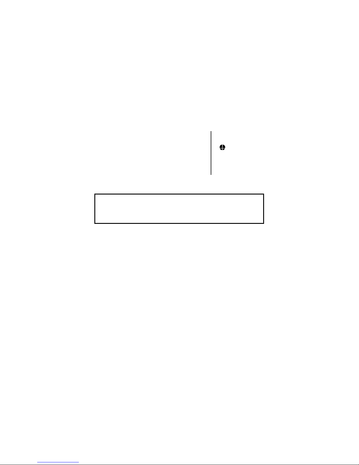
X-ray Identification
Lexos DR, DR-T, VR and VR-T
Implantable Cardioverter Defibrillator
Inside the housing, right-hand side:
X-Ray identification
Year of manufacture
C
AUTION
Federal (U.S.A.) law restricts this device to sale by, or on the
order of, a physician.
2003 BIOTRONIK, Inc., all rights reserved.
KV
nn

Contents
Lexos Technical Manual i
1. General...........................................................................1
1.1 System Description....................................................1
1.2 Indications and Usage ...............................................2
1.3 Contraindications .......................................................3
1.4 Warnings and Precautions.........................................3
1.4.1 Sterilization, Storage, and Handling ..................4
1.4.2 Device Implantation and Programming..............4
1.4.3 Lead Evaluation and Connection.......................6
1.4.4 Follow-up Testing...............................................8
1.4.5 Pulse Generator Explant and Disposal..............8
1.4.6 Hospital and Medical Hazards ...........................9
1.4.7 Home and Occupational Hazards......................10
1.4.8 Cellular Phones..................................................11
1.4.9 Electronic Article Surveillance (EAS).................12
1.4.10 Home Appliances ...............................................12
1.5 Adverse Events..........................................................13
1.5.1 Potential Adverse Events...................................13
1.5.2 Observed Adverse Events .................................14
1.6 Clinical Studies ..........................................................17
1.6.1 Tachos DR .........................................................17
1.6.2 Phylax AV...........................................................19
1.7 Patient Selection and Treatment ...............................21
1.7.1 Individualization of Treatment............................21
1.7.2 Specific Patient Populations ..............................22
1.8 Patient Counseling Information .................................23
1.9 Evaluating Prospective ICD Patients.........................23
2. Device Features ............................................................25
2.1 Sensing (Automatic Sensitivity Control) ....................25
2.1.1 Ventricular Sensitivity Settings ..........................25
2.1.2 Minimum Ventricular Threshold .........................28
2.1.3 Atrial Sensitivity Settings....................................28
2.1.4 Minimum Atrial Threshold ..................................29
2.1.5 Far Field Blanking ..............................................29

ii Lexos Technical Manual
2.2 Ventricular Tachyarrhythmia Detection ......................30
2.2.1 VF Classifications ..............................................31
2.2.2 VT Interval Counters ..........................................31
2.2.3 VT Classification ................................................31
2.2.4 SMART Detection™...........................................32
2.2.5 Onset..................................................................33
2.2.6 Stability...............................................................33
2.2.7 Sustained VT Timer ...........................................34
2.3 Tachyarrhythmia Redetection ....................................34
2.3.1 VT Redetection ..................................................35
2.3.2 SMART Redetection ..........................................35
2.3.3 VF Redetection ..................................................35
2.4 Tachyarrhythmia Termination.....................................35
2.5 Tachyarrhythmia Therapy ..........................................36
2.5.1 Therapy Options ................................................36
2.5.2 Anti-Tachycardia Pacing (ATP) .........................36
2.5.3 Shock Therapy...................................................39
2.5.4 Progressive Course of Therapy .........................42
2.6 Bradycardia Therapy .................................................43
2.6.1 Bradycardia Pacing Modes................................43
2.6.2 Basic Rate..........................................................44
2.6.3 Night Rate ..........................................................44
2.6.4 Rate Hysteresis..................................................44
2.6.5 Dynamic AV Delay .............................................48
2.6.6 Upper Tracking Rate..........................................49
2.6.7 Mode Switching..................................................50
2.6.8 PMT Management .............................................51
2.6.9 Rate Adaptive Pacing ........................................51
2.6.10 Pulse Amplitude .................................................53
2.6.11 Pulse Width ........................................................53
2.6.12 Post Ventricular Atrial Refractory Period ...........53
2.6.13 PVARP Extension ..............................................53
2.6.14 Noise Response.................................................54
2.6.15 Post Shock Pacing.............................................54
2.7 EP Test Functions ......................................................54

Lexos Technical Manual iii
2.7.1 P and R-wave Amplitude Measurments ............54
2.7.2 Testing for Retrograde Conduction....................55
2.7.3 Pacing Threshold ...............................................56
2.7.4 Arrhythmia Induction Features...........................56
2.7.5 Manual Shock ....................................................57
2.7.6 Manual ATP .......................................................57
2.7.7 Test Shock .........................................................57
2.8 Special Features........................................................58
2.8.1 Detection and Therapy Status ...........................58
2.8.2 Home Monitoring (Lexos DR-T and VR-T Only) 59
2.8.3 Real-time IEGM Transmission...........................64
2.8.4 Capacitor Reformation .......................................64
2.8.5 Patient and Implant Data ...................................65
2.8.6 System Status....................................................66
2.8.7 Holter Memory ...................................................66
2.8.8 Real-time IEGM .................................................69
2.8.9 Brady Diagnostics ..............................................70
3. Sterilization and Storage..............................................72
4. Implant Procedure ........................................................74
4.1 Implant Preparation ...................................................74
4.2 Lead System Evaluation ............................................76
4.3 Opening the Sterile Container ...................................76
4.4 Pocket Preparation ....................................................77
4.5 Lead to Device Connection .......................................78
4.6 Blind Plug Connection ...............................................81
4.7 Pacemaker Interaction Testing ..................................83
4.8 Program the ICD........................................................86
4.9 Implant the ICD..........................................................87
5. Follow-up Procedures ..................................................91
5.1 General Considerations.............................................91
5.2 Longevity....................................................................92
5.3 Explantation ...............................................................94
6. Technical Specifications ..............................................95
Appendix A...........................................................................103

iv Lexos Technical Manual
*Lexos VR and VR-T ICDs do not have an atrial pace/sense port
Lexos Specifications and Description
Battery Voltage: 6.3 Volts
Maximum Shock Energy: 30 joules
Defibrillation Lead Ports Two DF-1 (3.2 mm)
Pacing Lead Ports Two IS-1 (3.2 mm) (one
for Lexos VR and VR-T)
Dimension: 67 x 55 x 12 mm
Volume: 32 cc
Mass: 80 g
Housing Material: Titanium
Header Material: Epoxy Resin
Sealing Plug Material: Silicone
Battery Composition Li / MnO2

Lexos Technical Manual 1
1. General
1.1 System Description
The Lexos family of Implantable Cardioverter Defibrillators
(ICDs) detect and treat ventricular tachyarrhythmias and provide
rate adaptive bradycardia pacing support. The ICDs are
designed to collect diagnostic data to aid the physician’s
assessment of a patient’s condition and the performance of the
implanted device.
The Lexos ICDs provide therapy for ventricular tachyarrhythmias
with a sophisticated range of programmable anti-tachycardia
pacing (ATP), and/or defibrillation therapy. The shock polarity
and energy may be programmed to tailor the therapy to
appropriately treat each patient's tachyarrhythmias. The ICDs
provide shock therapies with programmable energies from 5 to
30 joules.

2 Lexos Technical Manual
The Lexos family of ICDs includes the following members:
• Lexos DR provides dual chamber rate adaptive
bradycardia pacing support. The ICD uses atrial and
ventricular sensing/pacing leads to provide enhanced
atrial and ventricular tachyarrhythmia discrimination
through BIOTRONIK’s SMART Detection
TM
algorithm.
• Lexos DR-T is identical to the Lexos DR with the added
functionality of BIOTRONIK’s Home Monitoring system.
The Home Monitoring System enables automatic
exchange of information about a patient’s cardiac status
from the implant to the physician remotely.
• Lexos VR provides single chamber rate adaptive
bradycardia pacing support.
• Lexos VR-T is identical to the Lexos VR with the added
functionality of BIOTRONIK’s Home Monitoring system.
The Home Monitoring System enables automatic
exchange of information about a patient’s cardiac status
from the implant to the physician remotely.
The Lexos DR and DR-T have two DF-1 defibrillation/
cardioversion and two IS-1 pacing/sensing header ports. The
Lexos VR and VR-T have two DF-1 defibrillation/ cardioversion
and one IS-1 pacing/sensing header ports. IS-1 refers to the
international standard whereby leads and generators from
different manufacturers are assured a basic fit [Reference ISO
5841-3:1992]. DF-1 refers to the international standard for
defibrillation lead connectors [Reference ISO 11318:1993].
External devices that interact with and test the implantable
devices are also part of the ICD System. These external devices
include the TMS 1000
and the EPR 1000
PLUS
PLUS
Tachyarrhythmia Monitoring System
Programming and Monitoring System.
These programmers are used to interrogate and program the
ICD.
1.2 Indications and Usage
The Lexos Implantable Cardioverter Defibrillators (ICDs) are
intended to provide ventricular anti-tachycardia pacing and
ventricular defibrillation, for automated treatment of lifethreatening ventricular arrhythmias.

Lexos Technical Manual 3
1.3 Contraindications
Do not use the Lexos Implantable Cardioverter Defibrillators
(ICDs) in patients:
• Whose ventricular tachyarrhythmias may have transient
or reversible causes including:
− acute myocardial infarction
− digitalis intoxication
− drowning
− electrocution
− electrolyte imbalance
− sepsis
− hypoxia
• Patients with incessant VT of VF
• Patients with unipolar pacemaker
• Patients whose only disorder is bradyarrhythmia or atrial
arrhythmia
1.4 Warnings and Precautions
MRI (Magnetic Resonance Imaging) - Do not expose a patient
to MRI device scanning. Strong magnetic fields may damage
the device and cause injury to the patient.
Electrical Isolation - To prevent inadvertent arrhythmia
induction, electrically isolate the patient during the implant
procedure from potentially hazardous leakage currents.
Lead Systems - The use of another manufacturer’s ICD lead
system may cause potential adverse consequences such as
under sensing of cardiac activity and failure to deliver necessary
therapy.
Resuscitation Availability - Do not perform induction testing
unless an alternate source of patient defibrillation such as an
external defibrillator is readily available. In order to implant the
ICD system, it is necessary to induce and convert the patient’s
ventricular tachyarrhythmias.

4 Lexos Technical Manual
Unwanted Shocks – Always program the VT/VF Detection and
Therapy status to DISABLED prior to handling the device to
prevent the delivery of serious shocks to the patient or the
person handling the device during the implant procedure.
Rate-Adaptive Pacing – Use rate-adaptive pacing with care in
patients unable to tolerate increased pacing rates.
1.4.1 Sterilization, Storage, and Handling
Device Packaging - Do not use the device if the device’s
packaging is wet, punctured, opened or damaged because the
integrity of the sterile packaging may be compromised. Return
the device to BIOTRONIK.
Re-sterilization - Do not re-sterilize and re-implant explanted
devices.
Storage (temperature) - Store the device between 5° to 55°C
(41° - 131° F) because temperatures outside this range could
damage the device.
Storage (magnets) - To avoid damage to the device, store the
device in a clean area, away from magnets, kits containing
magnets, and sources of electromagnetic interference (EMI).
Temperature Stabilization - Allow the device to reach room
temperature before programming or implanting the device
because temperature extremes may affect initial device function.
Use Before Date - Do not implant the device after the USE
BEFORE DATE because the device may have reduced
longevity.
1.4.2 Device Implantation and Programming
Blind Plug - A blind plug must be inserted and firmly connected
into any unused header port to prevent chronic fluid influx and
possible shunting of high energy therapy.

Lexos Technical Manual 5
Capacitor Reformation - Infrequent charging of the high voltage
capacitors may extend the charge times of the ICD. The
capacitors may be reformed manually, or the ICD may be
programmed to reform the capacitors automatically. For further
information, please refer to
Section 2.8.4
, Capacitor
Reformation.
Connector Compatibility - ICD and lead system compatibility
should be confirmed prior to the implant procedure. Consult
your BIOTRONIK representative regarding lead/pulse generator
compatibility prior to the implantation of an ICD system. For
further information, please refer to
Appendix A
.
ERI (Elective Replacement Indicator) - Upon reaching ERI, the
battery has sufficient energy remaining to continue monitoring for
at least three months and to deliver a minimum of six 30 joule
shocks. After this period, all tachyarrhythmia detection and
therapy is disabled. Bradycardia functions are still active at
programmed values until the battery voltage drops below
3.0 volts.
Magnets - Positioning of a magnet or the programming wand
over the ICD will suspend tachycardia detection and treatment.
The minimum magnet strength required to suspend tachycardia
treatment is 1.8 mT. When the magnet strength decreases to
less than 1 mT, the reed contact is reopened.
Pacemaker/ICD Interaction - In situations where an ICD and a
pacemaker are implanted in the same patient, interaction testing
should be completed. If the interaction between the ICD and the
pacemaker cannot be resolved through repositioning of the
leads or reprogramming of either the pacemaker or the ICD, the
pacemaker should not be implanted (or explanted if previously
implanted).
Programmed Parameters – Program the device parameters to
appropriate values based on the patient’s specific arrhythmias
and condition.
Programmers - Use only BIOTRONIK programmers to
communicate with the device (TMS 1000
PLUS
or EPR 1000
PLUS
).

6 Lexos Technical Manual
Sealing System - Failure to properly insert the torque wrench
into the perforation at an angle perpendicular to the connector
receptacle may result in damage to the sealing system and its
self-sealing properties.
Programming Wand Separation Distance – The wand must
not be placed closer than 2 cm to the device (implanted or out of
the box). Programming wand distance closer than 2 cm may
damage the device.
Defibrillation Threshold - Be aware that the changes in the
patient’s condition, drug regimen, and other factors may change
the defibrillation threshold (DFT) which may result in nonconversion of the arrhythmia post-operatively. Successful
conversion of ventricular fibrillation or ventricular tachycardia
during arrhythmia conversion testing is no assurance that
conversion will occur post-operatively.
Manual Shocks – User-commanded shocks may be withheld if
the ICD is already busy processing a manual command or the
Battery Status is low.
Charge Time - When preparing a high energy shock the charge
circuit stops charging the capacitors after 20 seconds, and
delivers the stored energy as shock therapy. After the device
reaches ERI the stored energy may be less than 30 joules per
shock.
Shock Therapy Confirmation – Programming
CONFIRMATION to OFF may increase the incidence of the ICD
delivering inappropriate shocks.
Shock Impedance - If the shock impedance is less than twentyfive ohms, reposition the lead system to allow a greater distance
between the electrodes. Never implant the device with a lead
system that has measured shock impedance as less than
twenty-five ohms. Damage to the device may result.
1.4.3 Lead Evaluation and Connection
Capping Leads - If a lead is abandoned rather than removed, it
must be capped to ensure that it is not a pathway for currents to
or from the heart.

Lexos Technical Manual 7
Gripping Leads - Do not grip the lead with surgical instruments
or use excessive force or surgical instruments to insert a stylet
into a lead.
Kinking Leads - Do not kink leads. This may cause additional
stress on the leads that can result in damage to the lead.
Liquid Immersion - Do not immerse leads in mineral oil, silicone
oil, or any other liquid.
Short Circuit - Ensure that none of the lead electrodes are in
contact (a short circuit) during delivery of shock therapy as this
may cause current to bypass the heart or cause damage to the
ICD system.
Far-field sensing of signals from the atrium in the ventricular
channel or ventricular signals in the atrial channel should be
avoided by appropriate lead placement, programming of
pacing/sensing parameters, and maximum sensitivity settings. If
it is necessary to modify the Far Field Blanking parameter, the
parameter should be lengthened only long enough to eliminate
far-field sensing as evidenced on the IEGMs. Extending the
parameter unnecessarily may cause under sensing of actual
atrial or ventricular events.
Suturing Leads - Do not suture directly over the lead body as
this may cause structural damage. Use the appropriate suture
sleeve to immobilize the lead and protect it against damage from
ligatures.
Tricuspid Valve Bioprosthesis - Use ventricular transvenous
leads with caution in patients with a tricuspid valvular
bioprosthesis.
Setscrew Adjustment – Back-off the setscrew(s) prior to
insertion of lead connector(s) as failure to do so may result in
damage to the lead(s), and/or difficulty connecting lead(s).
Cross Threading Setscrew(s) – To prevent cross threading
the setscrew(s), do not back the setscrew(s) completely out of
the threaded hole. Leave the torque wrench in the slot of the
setscrew(s) while the lead is inserted.
Tightening Setscrew(s) – Do not overtighten the setscrew(s).
Use only the BIOTRONIK supplied torque wrench.

8 Lexos Technical Manual
Sealing System – Be sure to properly insert the torque
wrench into the perforation at an angle perpendicular to the
connector receptacle. Failure to do so may result in damage to
the plug and its self-sealing properties.
1.4.4 Follow-up Testing
Defibrillation Threshold - Be aware that changes in the
patient’s condition, drug regimen, and other factors may change
the defibrillation threshold (DFT), which may result in nonconversion of the arrhythmia post-operatively. Successful
conversion of ventricular fibrillation or ventricular tachycardia
during arrhythmia conversion testing is no assurance that
conversion will occur post-operatively.
Resuscitation Availability - Ensure that an external defibrillator
and medical personnel skilled in cardiopulmonary resuscitation
(CPR) are present during post-implant device testing should the
patient require external rescue.
Safe Program – Within the EP Test screen, pressing the “Safe
Program” key on the programmer head does not immediately
send the safe program to the ICD. Pressing the “Safe Program”
key activates the emergency function screen, but an additional
screen touch is required to send the safe program to the ICD.
1.4.5 Pulse Generator Explant and Disposal
Device Incineration – Never incinerate the ICD due to the
potential for explosion. The ICD must be explanted prior to
cremation.
Explanted Devices – Return all explanted devices to
BIOTRONIK.
Unwanted Shocks – Always program the therapy status to
DISABLED prior to handling the device to prevent the delivery of
serious shocks to the patient or the person handling the device
during the implant procedure.

Lexos Technical Manual 9
1.4.6 Hospital and Medical Hazards
Electromagnetic interference (EMI) signals present in hospital
and medical environments may affect the function of any ICD or
pacemaker. The ICD is designed to selectively filter out EMI
noise. However, due to the variety of EMI signals, absolute
protection from EMI is not possible with this or any other ICD.
The ICD system should have detection and therapy disabled
prior to performing any of the following medical procedures. In
addition, the ICD should be checked after the procedures to
assure proper programming:
Diathermy - Diathermy therapy is not recommended for ICD
patients due to possible heating effects of the pulse generator
and at the implant site. If diathermy therapy must be used, it
should not be applied in the immediate vicinity of the pulse
generator or lead system.
Electrocautery - Electrosurgical cautery could induce ventricular
arrhythmias and/or fibrillation, or may cause device malfunction
or damage. If use of electrocautery is necessary, the current
path and ground plate should be kept as far away from the pulse
generator and leads as possible (at least 6 inches (15 cm)).
External Defibrillation - The device is protected against energy
normally encountered from external defibrillation. However, any
implanted device may be damaged by external defibrillation
procedures. In addition, external defibrillation may also result in
permanent myocardial damage at the electrode-tissue interface as
well as temporary or permanent elevated pacing thresholds. When
possible, observe the following precautions:

10 Lexos Technical Manual
• Position the adhesive electrodes or defibrillation paddles
of the external defibrillator anterior-posterior or along a
line perpendicular to the axis formed by the implanted
device and the heart.
• Set the energy to a level not higher than is required to
achieve defibrillation.
• Place the paddles as far as possible away from the
implanted device and lead system.
• After delivery of an external defibrillation shock,
interrogate the ICD to confirm device status and proper
function.
Lithotripsy - Lithotripsy may damage the ICD. If lithotripsy must
be used, avoid focusing near the ICD implant site.
MRI (Magnetic Resonance Imaging) - Do not expose a patient
to MRI device scanning. Strong magnetic fields may damage
the device and cause injury to the patient.
Radiation - High radiation sources such as cobalt 60 or gamma
radiation should not be directed at the pulse generator. If a
patient requires radiation therapy in the vicinity of the pulse
generator, place lead shielding over the device to prevent
radiation damage and confirm its function after treatment.
Radio Frequency Ablation - Prior to performing an ablation
procedure, deactivate the ICD during the procedure. Avoid
applying ablation energy near the implanted lead system
whenever possible.
1.4.7 Home and Occupational Hazards
Patients should be directed to avoid devices that generate strong
electromagnetic interference (EMI) or magnetic fields. EMI could
cause device malfunction or damage resulting in non-detection
or delivery of unneeded therapy. Moving away from the source
or turning it off will usually allow the ICD to return to its normal
mode of operation.

Lexos Technical Manual 11
The following equipment (and similar devices) may affect normal
ICD operation: electric arc or resistance welders, electric melting
fu r na c es , r ad i o/t e le v isi on and radar t r an s mi t ter s ,
power-generating facilities, high-voltage transmission lines, and
electrical ignition systems (of gasoline-powered devices) if
protective hoods, shrouds, etc., are removed.
1.4.8 Cellular Phones
Testing has indicated there may be a potential interaction
between cellular phones and BIOTRONIK ICD systems.
Potential effects may be due to either the cellular phone signal or
the magnet within the telephone and may include inhibition of
therapy when the telephone is within 6 inches (15 cm) of the
ICD, when the ICD is programmed to standard sensitivity.
Patients having an implanted BIOTRONIK ICD who operate a
cellular telephone should:
• Maintain a minimum separation of 6 inches (15 cm)
between a hand-held personal cellular telephone and
the implanted device.
• Set the telephone to the lowest available power setting,
if possible.
• Patients should hold the phone to the ear opposite the
side of the implanted device. Patients should not carry
the telephone in a breast pocket or on a belt over or
within 6 inches (15 cm) of the implanted device as some
telephones emit signals when they are turned ON, but
not in use (i.e., in the listen or stand-by mode). Store
the telephone in a location opposite the side of implant.
Based on results to date, adverse effects resulting from
interactions between cellular telephones and implanted ICDs
have been transitory. The potential adverse effects could
include inhibition or delivery of additional therapies. If
electromagnetic interference (EMI) emitting from a telephone
does adversely affect an implanted ICD, moving the telephone
away from the immediate vicinity of the ICD should restore
normal operation. A recommendation to address every specific
interaction of EMI with implanted ICDs is not possible due to the
disparate nature of EMI.

12 Lexos Technical Manual
1.4.9 Electronic Article Surveillance (EAS)
Equipment such as retail theft prevention systems may interact
with pulse generators. Patients should be advised to walk
directly through and not to remain near an EAS system longer
than necessary.
1.4.10 Home Appliances
Home appliances normally do not affect ICD operation if the
appliances are in proper working condition and correctly
grounded and shielded. There have been reports of the
interaction of electric tools or other external devices (e.g. electric
drills, older models of microwave ovens, electric razors, etc.)
with ICDs when they are placed in close proximity to the device.

Lexos Technical Manual 13
1.5 Adverse Events
1.5.1 Potential Adverse Events
The following is a list of the potential risks that may occur with
this device:
• Acceleration of arrhythmias
• Air embolism
• Bleeding
• Chronic nerve damage
• Erosion
• Excessive fibrotic tissue growth
• Extrusion
• Fluid accumulation
• Formation of hematomas or cysts
• Inappropriate shocks
• Infection
• Keloid formation
• Lead abrasion and discontinuity
• Lead migration / dislodgment
• Myocardial damage
• Pneumothorax
• Shunting current or insulating myocardium during
defibrillation with internal or external paddles
• Potential mortality due to inability to defibrillate or pace
• Thromboemboli
• Venous occlusion
• Venous or cardiac perforation
Patients susceptible to frequent shocks despite antiarrhythmic
medical management may develop psychological intolerance to
an ICD system that may include the following:
• Dependency
• Depression

14 Lexos Technical Manual
• Fear of premature battery depletion
• Fear of shocking while conscious
• Fear that shocking capability may be lost
• Imagined shocking (phantom shock)
There may be other risks associated with this device that are
currently unforeseeable.
1.5.2 Observed Adverse Events
A clinical study of the Phylax AV involved 128 devices implanted
in 126 patients with a cumulative implant duration of 795.5
months (mean implant duration 6.3 months).
N
There were a total of two deaths during the course of the trial;
neither of which was judged by the clinical study investigator to
be device related. The two deaths were related to heart failure
and pneumonia. Both of the deaths occurred more than three
months post implant.
Three devices were explanted during the trial. One device was
explanted secondary to the patient reporting pain at the implant
site; the patient was subsequently implanted with another
device. One device was explanted due to a random component
failure, and the other device was explanted after reaching ERI,
which was anticipated based on the number of shocks delivered.
These two patients were subsequently implanted with other
Phylax AV ICDs.
Table 1
reported during the clinical study regardless of whether or not
the event was related to the ICD system. A complication was
defined as a clinical event that resulted in additional invasive
intervention, injury, or death. An observation was defined as a
clinical event that did not result in additional invasive
intervention, injury, or death.
:
OTE
The Phylax AV ICD is an earlier generation of BIOTRONIK
devices. The Lexos family is based upon the Phylax AV and
other BIOTRONIK ICDs (i.e., Phylax, Tachos, and Belos
families of ICDs).
provides a summary of the adverse events that were

Lexos Technical Manual 15
Table 1: Reported Adverse Events
# of
Complications Total
Patients
with AEs
14 11.1% 18 0.27
% of
Patients
with AEs
# of
AEs
AE /
pt-yrs
Lead Repositioning 10 7.9% 12 0.18
Discomfort at Implant
1 0.8% 1 0.02
Site
Infection 1 0.8% 1 0.02
Thrombus 1 0.8% 1 0.02
Pneumothorax 1 0.8% 1 0.02
ERI 1 0.8% 1 0.02
Random Component
1 0.8% 1 0.02
Failure
Observations Total
47 37.3% 74 1.12
T-wave Oversensing 7 5.6% 7 0.11
Increased Pacing
7 5.6% 7 0.11
Threshold
Required antiarrhythmic
7 5.6% 7 0.11
drug therapy
SVT Therapy-Unrelated
6 4.8% 8 0.12
to SMART
Software version IGAV.1.U
1
6 4.8% 6 0.09
Detection 5 4.0% 5 0.08
Lead revision at implant 5 4.0% 5 0.08
TMS 10002 4 3.2% 4 0.06
Lead difficulties at
3 2.4% 3 0.05
Implant
Difficulties with
3 2.4% 3 0.05
Telemetry
Atrial Lead Dislodgment 2 1.6% 2 0.03

16 Lexos Technical Manual
# of
SVT Therapy-Related to
Patients
with AEs
2 1.6% 4 0.06
% of
Patients
with AEs
# of
AEs
AE /
pt-yrs
SMART
Initial therapy did not
2 1.6% 2 0.03
convert VT/VF
Low P/R-Wave
2 1.6% 2 0.03
Amplitude
Intermittent Under /
2 1.6% 2 0.03
Oversensing
Lead Repositioning at
2 1.6% 2 0.03
implant
Asynchronous Pacing 2 1.6% 2 0.03
Atrial Arrhythmias 2 1.6% 2 0.03
Atrial arrhythmia with
1 0.8% 1 0.02
ventrical tracking
External cardioversion
1 0.8% 1 0.02
due to AT
P-wave changes with
1 0.8% 1 0.02
position
Patient Symptomatic at
1 0.8% 1 0.02
Upper Tracking Rate
Diaphragmatic Pacing 1 0.8% 1 0.02
Myocardial Infarction 1 0.8% 1 0.02
Cautery caused Shock
1 0.8% 1 0.02
Delivery
Phantom programming 1 0.8% 1 0.02
Number of Patients = 126, Number of Patient-Years = 66.3,
see next page for notes on table.

Lexos Technical Manual 17
1. This category includes various anomalies that were
related to the programmer software used in the clinical study,
I-GAV.1.U. Each of these events has been resolved
through revisions to the programmer software resulting
in version I-GAV.2.U.
2. This category includes any difficulties encountered while
using the TMS 1000
System, which is a commercially available device that
was used during the clinical investigation.
PLUS
Tachyarrhythmia Monitoring
1.6 Clinical Studies
1.6.1 Tachos DR
The Tachos DR clinical evaluation involved 57 patients
implanted with a Tachos DR outside of the United States.
N
:
OTE
The clinical study information included in this technical
manual was performed with the Phylax AV and Tachos DR
ICDs. The Lexos DR is a downsized version of the
Belos DR, which was also based on and approved with this
data. The clinical study data presented here is applicable
because the Lexos ICDs are downsized versions of the
Belos and Tachos families of ICDs. The Lexos ICDs are
slightly different as compared to the Belos ICDs in the
following areas:
− Reduced size from 39 cc to 32 cc
− Additional shock waveform - Biphasic 2ms (see
Section 2.5.3.3
− Upper Tracking Rate (UTR) programmable in the
VT-1 therapy zone
− Minimum shock energy is 5 Joules
Due to the similarities between the Lexos family and Phylax,
Tachos, and Belos families of ICDs and the limited nature of
these changes, a clinical study of the Lexos DR/DR-T ICD
was determined to be unnecessary.
)

18 Lexos Technical Manual
1.6.1.1 Study Objectives
The objective of the clinical evaluation was to gather basic
information about the function and performance of the
Tachos DR ICD in patients with standard ICD indications.
1.6.1.2 Results
The mean implant duration was 5.7 months with cumulative
implant duration of 323 patient months. No unanticipated events
were reported during the evaluation. A summary of the results
obtained during the evaluation is provided in the following table.
1.6.1.3 Survival
During the initial experience outside of the United States with the
Tachos DR, there have been no sudden cardiac deaths
reported. There was one death reported, which was unrelated to
the implanted device.
Table 2: Tachos DR Study Results
Evaluation Results
Appropriate Atrial Sensing and Pacing 99% (126/127)
Appropriate Ventricular Sensing and
Pacing
99% (122/123)
Appropriate Ventricular
Tachyarrhythmia Detection and
96% (116/121)
Conversion
Complication Rate (per patient) 3.5%
Complication Rate (per patient-year) 0.074
Sudden Cardiac Death Survival Rate 100%
Overall Survival Rate 98%

Lexos Technical Manual 19
1.6.2 Phylax AV
The Phylax AV clinical study involved 126 patients (111 males
(88.1%) and 15 females (11.9%) with a mean age of 66 years
(range: 22-87 years) and a left ventricular ejection fraction of
31% (range: 10-60%). Most patients (80.2%) presented with
coronary artery disease / ischemic cardiomyopathy; 65.1%
presented with monomorphic ventricular tachycardia (MVT) as
their primary tachyarrhythmia.
N
1.6.2.1 Methods
The multi-center, non-randomized clinical investigation was
designed to validate the safety and effectiveness of the
Phylax AV through an analysis of the unanticipated adverse
device effect (UADE) rate. The specific predefined objectives of
the investigation included UADE-free survival rate, morbidity
rate, sudden cardiac death (SCD) survival rate, the appropriate
sensing and pacing rate, detection and conversion of ventricular
tachyarrhythmias, and the appropriate rejection of atrial
tachyarrhythmias.
1.6.2.2 Results
The mean implant duration was 6.3 ± 0.4 months with
cumulative implant duration of 795.5 months. There were 20
patients followed for over twelve months and 62 patients
followed for over six months during the study period from
February 5, 1999 to April 15, 2000. The patient follow-up
compliance rate was 98.4% out of 319 required follow-ups.
Table 3
the predefined endpoints.
:
OTE
The Phylax AV ICD is an earlier generation of BIOTRONIK
devices. The Lexos family is based upon the Phylax AV and
other BIOTRONIK ICDs (i.e., Phylax, Tachos, and Belos
families of ICDs). Therefore, the clinical data from the
Phylax AV was used to support the safety and effectiveness
of the Lexos DR.
provides a summary of the results of the study group for

20 Lexos Technical Manual
Table 3: Clinical Study Results
Description
UADE-free Survival Rate
(patients with at least 3 months
follow-up)
Complication Rate
Sudden Cardiac Death Survival Rate
Appropriate Bradycardia Sensing and
Pacing Rate
Detection and Conversion of
Ventricular Tachyarrhythmias
Appropriate Rejection of
Atrial Tachyarrhythmias
Study Group
[95% CI]
100% (85/85)
[96.5%, 100%]
11.1% (14/126)
[0%, 16.8%]
100% (124/124)
[97.6% 100%]
96.2%(1141/1186
)
[95.2%, 100%]
98.2% (650/662)
[97.1%, 100%]
94% (138/147)
[89.6%, 100%]
1.6.2.3 SMART Detection Algorithm
The SMART Detection algorithm is an integral function of
BIOTRONIK’s dual chamber ICD product line (i.e., Phylax AV,
Tachos DR, and Belos DR) and is designed to discriminate lifethreatening ventricular tachycardias from relatively harmless
atrial tachyarrhythmias. This algorithm uses information about
the signals from the atrial and ventricular lead systems and is
designed to reduce the amount of inappropriate therapy that
might be delivered as a result of a supraventricular tachycardia
(SVT). Neither the SMART Detection algorithm nor the ICDs are
designed to detect or deliver therapy to terminate atrial
arrhythmias, and therefore this is not the purpose of the
algorithm or the device.

Lexos Technical Manual 21
During the Phylax AV clinical study, specific data was collected
to demonstrate the ability of the SMART Detection algorithm to
discriminate between SVT and VT. The Phylax AV
demonstrated the ability to withhold inappropriate therapy in
approximately 94% of the SVT episodes that were reported
during the study. In addition, the SMART Detection algorithm
appropriately delivered therapy in 100% of the ventricular
episodes in which the feature was activated. At routine followups, the algorithm was activated in 80% of patients enrolled into
the study, which further supports the overall ability of the
algorithm to appropriately discriminate between SVT and VT. In
addition, during the clinical study, the investigators indicated that
the primary reason for selecting a dual-chamber ICD was SVT
discrimination for 70% of the patients enrolled.
1.7 Patient Selection and Treatment
1.7.1 Individualization of Treatment
• Determine whether the expected device benefits
outweigh the possibility of early device replacement for
patients whose ventricular tachyarrhythmias require
frequent shocks.
• Determine if the device and programmable options are
appropriate for patients with drug-resistant
supraventricular tachyarrhythmias (SVTs), because
drug-resistant SVTs can initiate unwanted device
therapy.
• Direct any questions regarding individualization of
patient therapy to your BIOTRONIK representative or
BIOTRONIK technical services at 1-800-547-0394.
The prospective patient’s size and activity level should be
evaluated to determine whether a pectoral or abdominal implant
is suitable. It is strongly recommended that candidates for an
ICD have a complete cardiac evaluation including EP testing
prior to device implant to gather electrophysiologic information,
including the rates and classifications of all the patient’s cardiac
rhythms. When gathering this information, delineate all clinically
significant ventricular and atrial arrhythmias, whether they occur
spontaneously or during EP testing.

22 Lexos Technical Manual
If the patient’s condition permits, use exercise stress testing to
do the following:
• Determine the maximum rate of the patient’s normal
rhythm.
• Identify any supraventricular tachyarrhythmias.
• Identify exercise-induced tachyarrhythmias.
The maximum exercise rate or the presence of supraventricular
tachyarrhythmias may influence selection of programmable
parameters. Holter monitoring or other extended ECG
monitoring also may be helpful.
If the patient is being treated with antiarrhythmic or cardiac
drugs, the patient should be on a maintenance drug dose rather
than a loading dose at the time of pulse generator implantation.
If changes to drug therapy are made, repeated arrhythmia
inductions are recommended to verify pulse generator detection
and conversion. The pulse generator also may need to be
reprogrammed.
Changes in a patient’s antiarrhythmic drug or any other
medication that affect the patient’s normal cardiac rate or
conduction can affect the rate of tachyarrhythmias and/or
efficacy of therapy.
If another cardiac surgical procedure is performed prior to
implanting the pulse generator, it may be preferable to implant
the lead system at that time. This may prevent the need for an
additional thoracic operation.
1.7.2 Specific Patient Populations
Pregnancy - If there is a need to image the device, care should
be taken to minimize radiation exposure to the fetus and the
mother.
Nursing Mothers - Although appropriate biocompatibility testing
has been conducted for this implant device, there has been no
quantitative assessment of the presence of leachables in breast
milk.
Geriatric Patients - Most (72%) of the patients receiving an ICD
in the Phylax AV clinical study were over the age of 60 years
(see Clinical Studies).

Lexos Technical Manual 23
Handicapped and Disabled Patients - Special care is needed
in using this device for patients using an electrical wheel chair or
other electrical (external or implanted) devices.
1.8 Patient Counseling Information
The pulse generator is subject to random component failure.
Such failure could cause inappropriate shocks, induction of
arrhythmias or inability to sense arrhythmias, and could lead to
the patient’s death.
Persons administering CPR may experience the presence of
voltage on the patient’s body surface (tingling) when the patient’s
ICD system delivers a shock.
A patient manual is available for the patient, patient’s relatives,
and other interested people. Discuss the information in the
manual with concerned individuals both before and after pulse
generator implantation so they are fully familiar with operation of
the device. (For additional copies of the patient manual, contact
the BIOTRONIK at the address listed in this manual.)
1.9 Evaluating Prospective ICD Patients
The prospective ICD implant candidate should undergo a
cardiac evaluation to classify any and all tachyarrhythmias. In
addition, other patient specific cardiac information will help in
selecting the optimal device settings. This evaluation may
include, but is not limited to:
• an evaluation of the specific tachycardia rate(s)
• the confirmation and/or evaluation of any
supraventricular arrhythmias or bradyarrhythmias
• the evaluation of various ATP and cardioversion
therapies
• the presence of any post-shock arrhythmias, and
• an evaluation of the maximum sinus rate during exercise
If a patient’s drug regimen is changed or adjusted while the ICD
is implanted, additional EP testing may be required to determine
if detection or therapy parameter settings are relevant and
appropriate.

24 Lexos Technical Manual
Empirical changes to the detection or therapy parameters should
be assessed based on patient safety. Some changes may
necessitate a re-assessment of sensing, pacing, or arrhythmia
conversion treatment. Thorough technical knowledge of
BIOTRONIK ICDs, additional ICD experience, and individual
medical judgment will aid in determining the need for additional
testing and follow-up.
 Loading...