

Page 1
Evia HF(-T)
Pacemaker • Bradyarrhythmia Therapy • Cardiac Resynchronization Therapy
Kardiostimulátor • Léčba bradyarhytmie • Kardiální resynchronizační léčba
Pacemaker • Bradyarytmiterapi • Kardial resynkroniseringsbehandling
Herzschrittmacher • Bradyarrhythmietherapie • Kardiale Resynchronisationstherapie
Marcapasos • Terapia bradiarritmia • Terapia de resincronización cardiaca
Sydämentahdistin • Bradykardisen rytmihäiriön hoito • Sydämen resynkronisaatiohoito
Stimulateur cardiaque • Traitement de la bradyarythmie • Traitement par resynchronisation cardiaque
Pacemaker • Bradiarritmia terápia • Kardiális reszinkronizációs terápia
Pacemaker • Terapia per bradiaritmia • Terapia di resincronizzazione cardiaca
Pacemaker • Bradyaritmietherapie • Cardiale resynchronisatietherapie
Pacemakere • Bradyarytmibehandling • Kardial resynkroniseringsbehandling
Stymulator serca • Leczenie bradyarytmii • Terapia resynchronizująca serca
Marcapasso • Terapia de bradiarritmia • Terapia de ressincronização cardíaca
Pacemaker • Bradyarytmibehandling • Kardiell resynkroniseringsbehandling
Technical manual
Technická příručka
Brugermanual
Gebrauchsanweisung
Manual técnico
Käyttöohje
Manuel technique
Használati útmutató
Manuale tecnico
Technische handleiding
Manual
Instrukcja obsługi
Manual técnico
Bruksanvisning
• en
• cs
• da
• de
• es
•
• fr
• hu
• it
• nl
• no
• pl
• pt
• sv
Page 2

en • English ................................................................................................................................................................. 2
cs • Česky .................................................................................................................................................................... 23
da • Dansk ................................................................................................................................................................... 44
de • Deutsch ................................................................................................................................................................ 65
es • Español ................................................................................................................................................................. 86
fi • Suomi ................................................................................................................................................................... 108
fr • Français ............................................................................................................................................................... 129
hu • Magyar .................................................................................................................................................................. 151
it • Italiano ................................................................................................................................................................. 172
nl • Nederlands .......................................................................................................................................................... 193
no • Norsk .................................................................................................................................................................... 214
pl • Polski .................................................................................................................................................................... 235
pt • Português ............................................................................................................................................................. 257
sv • Svenska ................................................................................................................................................................ 278
387513--D
Page 3

en • English
Product Description . . . . . . . . . . . . . . . . . . . . . . . . . . . . . . . . . . . . . . . . . . . . . . . . . . . . . . 2
Intended Medical Use . . . . . . . . . . . . . . . . . . . . . . . . . . . . . . . . . . . . . . . . . . . . . . . 2
System Overview. . . . . . . . . . . . . . . . . . . . . . . . . . . . . . . . . . . . . . . . . . . . . . . . . . . 2
Device Variants and NBG Codes . . . . . . . . . . . . . . . . . . . . . . . . . . . . . . . . . . . . . . 4
Diagnostic and Therapy Functions . . . . . . . . . . . . . . . . . . . . . . . . . . . . . . . . . . . . 4
Package Contents . . . . . . . . . . . . . . . . . . . . . . . . . . . . . . . . . . . . . . . . . . . . . . . . . . 5
General Safety Instructions . . . . . . . . . . . . . . . . . . . . . . . . . . . . . . . . . . . . . . . . . . . . . . . . 5
Possible Medical Complications . . . . . . . . . . . . . . . . . . . . . . . . . . . . . . . . . . . . . . 5
Possible Technical Complications. . . . . . . . . . . . . . . . . . . . . . . . . . . . . . . . . . . . . 6
Possible Electromagnetic Complications . . . . . . . . . . . . . . . . . . . . . . . . . . . . . . . 6
Possible Risks. . . . . . . . . . . . . . . . . . . . . . . . . . . . . . . . . . . . . . . . . . . . . . . . . . . . . 6
Prior to Implantation. . . . . . . . . . . . . . . . . . . . . . . . . . . . . . . . . . . . . . . . . . . . . . . . . . . . . . 7
Indications and Contraindications . . . . . . . . . . . . . . . . . . . . . . . . . . . . . . . . . . . . . 7
Ambient Conditions. . . . . . . . . . . . . . . . . . . . . . . . . . . . . . . . . . . . . . . . . . . . . . . . . 7
Sterility. . . . . . . . . . . . . . . . . . . . . . . . . . . . . . . . . . . . . . . . . . . . . . . . . . . . . . . . . . . 8
Preparing the Implantation . . . . . . . . . . . . . . . . . . . . . . . . . . . . . . . . . . . . . . . . . . 8
Implantation. . . . . . . . . . . . . . . . . . . . . . . . . . . . . . . . . . . . . . . . . . . . . . . . . . . . . . . . . . . . . 8
Implanting . . . . . . . . . . . . . . . . . . . . . . . . . . . . . . . . . . . . . . . . . . . . . . . . . . . . . . . . 8
Connecting Pacemaker Leads. . . . . . . . . . . . . . . . . . . . . . . . . . . . . . . . . . . . . . . . 9
Precautionary Measures while Programming . . . . . . . . . . . . . . . . . . . . . . . . . . 10
After Implantation . . . . . . . . . . . . . . . . . . . . . . . . . . . . . . . . . . . . . . . . . . . . . . . . . . . . . . 12
Follow-up. . . . . . . . . . . . . . . . . . . . . . . . . . . . . . . . . . . . . . . . . . . . . . . . . . . . . . . . 12
Notes for the Physician . . . . . . . . . . . . . . . . . . . . . . . . . . . . . . . . . . . . . . . . . . . . 12
Replacement Indications . . . . . . . . . . . . . . . . . . . . . . . . . . . . . . . . . . . . . . . . . . . 13
Explantation and Device Replacement . . . . . . . . . . . . . . . . . . . . . . . . . . . . . . . . 14
Parameters . . . . . . . . . . . . . . . . . . . . . . . . . . . . . . . . . . . . . . . . . . . . . . . . . . . . . . . . . . . . 14
Modes. . . . . . . . . . . . . . . . . . . . . . . . . . . . . . . . . . . . . . . . . . . . . . . . . . . . . . . . . . . 14
Timing: Triple-Chamber. . . . . . . . . . . . . . . . . . . . . . . . . . . . . . . . . . . . . . . . . . . . 15
Pacing and Sensing: Triple-Chamber . . . . . . . . . . . . . . . . . . . . . . . . . . . . . . . . . 16
Rate Adaptation . . . . . . . . . . . . . . . . . . . . . . . . . . . . . . . . . . . . . . . . . . . . . . . . . . 17
Preset programs: Triple-Chamber . . . . . . . . . . . . . . . . . . . . . . . . . . . . . . . . . . . 18
Tolerances of Parameter Values . . . . . . . . . . . . . . . . . . . . . . . . . . . . . . . . . . . . . 19
Table of Contents
Technical Data . . . . . . . . . . . . . . . . . . . . . . . . . . . . . . . . . . . . . . . . . . . . . . . . . . . . . . . . . . 19
Mechanical Characteristics . . . . . . . . . . . . . . . . . . . . . . . . . . . . . . . . . . . . . . . . . 19
Electrical Characteristics . . . . . . . . . . . . . . . . . . . . . . . . . . . . . . . . . . . . . . . . . . . 20
Battery Data. . . . . . . . . . . . . . . . . . . . . . . . . . . . . . . . . . . . . . . . . . . . . . . . . . . . . . 20
Legend for the Label. . . . . . . . . . . . . . . . . . . . . . . . . . . . . . . . . . . . . . . . . . . . . . . 22
1 Product Description
Intended Medical Use
Intended use
Evia is a family of implantable pacemakers that may be implanted for all bradycardia
arrhythmia indications. The primary objective of the therapy consists of improving
patients' symptoms that can be clinically manifested. The implantation of the pacemaker is a symptomatic therapy with the following objective:
•
Compensation of bradycardia by atrial, ventricular, or AV sequential pacing
•
Resynchronization of ventricular chamber contraction via biventricular pacing
Diagnosis and therapy forms
The cardiac rhythm is automatically monitored and bradycardia arrhythmias are
treated. All major therapeutic approaches from the field of cardiology and electrophysiology are unified in the Evia family. BIOTRONIK Home Monitoring® enables
physicians to perform therapy management at any time.
Required expertise
In addition to having basic medical knowledge, the user must be thoroughly familiar
with the operation of a device system.
•
Only qualified medical specialists having the special knowledge required for the
proper use of implanted devices are permitted to use them.
•
If users do not possess this knowledge, they must be trained accordingly.
System Overview
Device family
Evia HF and Evia HF-T are triple-chamber devices and belong to the Evia family. Not all
device types are available in every country.
2
Page 4

Parts
The device system consists of the following parts:
•
Device with connections for unipolar or bipolar sensing and pacing
•
Suitable leads, adapters and approved accessories
•
Programmer
•
Current software
Device
The device's housing is made of biocompatible titanium, welded from outside and thus
hermetically sealed. The ellipsoid shape facilitates ingrowth into the pectoral muscle
area. The housing serves as an antipole in the case of unipolar lead configuration.
BIOTRONIK provides silicone-coated devices to avoid muscle twitching near the
implanted pacemaker in the case of unipolar pacing. The labeling provides information
about the device type and arrangement of the connections.
Leads
The leads are coated with biocompatible silicone. They can be flexibly maneuvered, are
stable long-term, and are equipped for active or passive fixation. They are implanted
using a lead introducer set. Some leads are coated with polyurethane which is known to
increase the sliding properties for the lead. The coating of steroid-eluting leads
reduces inflammatory processes. The fractal design of the leads allows for low pacing
thresholds, high pacing impedance, and a low risk of oversensing.
Programmer
The portable programmer is used to transfer the current software to the device. In
addition to this, the programmer is used for interrogation and storage of data from the
device. The programmer acts as an ECG and IEGM monitor.
Note:
It is not permitted to use the device's ECG display for diagnostic purposes
because it does not meet all requirements of the norm (IEC 60601-2-25) concerning
diagnostic ECG devices.
The programmer communicates with the device via the programming head. It has a TFT
touch screen with a color display, on which the ECG, IEGM, markers and functions are
shown simultaneously. The programmer functions include the following:
•
Perform all tests during in-office follow-up
•
Display and print real-time and saved IEGMs with annotated markers
•
Determine the pacing threshold
BIOTRONIK Home Monitoring
In addition to effective pacing therapy, BIOTRONIK provides a complete therapy
management system:
•
With Home Monitoring, diagnostic and therapeutic information and technical data
are automatically sent to a stationary or mobile transmitter via an antenna in the
device's header. The data are encrypted and sent from the transmitter to the
BIOTRONIK Service Center via the cellular phone network.
•
The received data are deciphered and evaluated. Each physician can set the criteria
for evaluation to be used for each patient and can configure the time of notification
via e-mail, SMS or fax.
•
A clear overview of the results of this analysis is displayed for the attending physicians on the protected internet platform Home Monitoring Service Center (HMSC).
•
Data transmission from the device is performed with a daily device message.
•
Device messages, which indicate special events in the patient's heart or in the
device, are forwarded immediately.
•
A test message can be initiated at any time using the programmer to immediately
check the Home Monitoring function.
®
Technical manuals
The following technical manuals provide information about usage of the device
systems:
•
Technical manual for the device
•
Technical manual for the HMSC
•
Technical manuals for the programmer
•
Technical manual for software as online help on the user interface and as a PDF
file in the Manual Library at www.BIOTRONIK.com
•
Technical manuals for the leads
•
Technical manuals for cables, adapters and accessories
en • English
3
Page 5

Device Variants and NBG Codes
Evia family
The following device variants are available:
Device type Variant with
Triple-chamber Evia HF-T Evia HF
Note:
The setting of the mode depends on individual diagnosis. The modes are listed
in the section pertaining to adjustable parameters.
NBG code for Evia HF(-T)
DDDRV is the NBG code for the antibradycardia mode of the triple-chamber device:
D Pacing in the atrium and ventricle
D Sensing in the atrium and ventricle
D Pulse inhibition and pulse triggering
R Rate adaptation
V Multisite pacing in both ventricles
Home Monitoring
Variant without
Home Monitoring
Diagnostic and Therapy Functions
General overview
All the systems have extensive features that allow quick diagnosis and delivery of safe
therapy for bradycardia conditions.
•
Automatic functions make it easy and fast to implant, configure, and check the
pacemaker.
•
Auto-initialization after implantation: the device automatically detects the
implanted leads, sets the polarity and activates the automatic functions after
10 min.
Diagnostic functions
•
Data from the last 10 interrogations and follow-ups are recorded as well as
arrhythmia episodes; they are stored together with other data to assess patients
and the state of the device at any time.
•
Automatic below-threshold impedance measurement is performed in the device
independent of the pacing pulse in order to check the lead for proper functioning.
•
When performing follow-ups using the programmer, the IEGM is indicated with
markers after applying the programming head during the test procedure.
Antibradycardia pacing
•
Sensing: the amplitudes of the P and R waves are measured in the implanted device
fully automatically to record varying amplitudes. The sensitivity for the atrium and
ventricle is adapted automatically on an ongoing basis. The measurement data are
averaged and the trend can be displayed.
•
Thresholds: atrial as well as ventricular pacing thresholds are automatically determined in the device. Capture control is used to set the pulse amplitudes so that
pacing is performed with the optimum atrial and ventricular amplitude for the
patients with each change of the pacing threshold.
•
Timing: pacing is checked particularly carefully in the atrium. The atrial refractory
period is adapted automatically in order to avoid pacemaker-induced tachycardia.
(Auto PVARP function: automatic post-ventricular atrial refractory period)
•
Additional, special form of rate adaptation: an increased cardiac output requirement is detected using physiological impedance measurement. The measuring
principle is based on contractile changes (inotropy) of the myocardium (CLS function: Closed Loop Stimulation). The suitable rate adaptation is automatically initialized and optimized in CLS mode.
•
Ventricular pacing suppression: unnecessary ventricular pacing is avoided by
promoting intrinsic conduction (Vp suppression function). The device can adapt
itself to conduction changes. In the case of intrinsic conduction, the device switches
to a DDD(R)-ADI(R) mode.
Resynchronization therapy
For resynchronization of the ventricles, triple-chamber implants have functions for
multisite pacing with possible VV delays in either direction.
•
Capture Control is available for the left ventricle with automated tracking of the
pacing threshold or automatic threshold monitoring (ATM) for trend analysis.
•
To ensure that no additional surgery is necessary in case of a left-sided increase of
pacing threshold or undesired phrenic nerve stimulation, di fferent pacing polarities
can be set for the left ventricular lead with a triple-chamber device.
4
Page 6

•
An additional diagnostic function with biventricular pacing: variability of the heart
rate, the patient activity and the thoracic impedance are monitored on a continual
basis.
Programs
There are two types of therapy programs:
•
Default parameters are offered for the most common indications (Program Consult
function).
•
Individual settings can be saved in three individual therapy programs.
Home Monitoring functions
The device automatically sends information to the transmitter once a day. Additionally,
the test messages can be initiated using the programmer. Important medical information include, among others, the following:
•
Ongoing atrial and ventricular arrhythmia
•
Parameters relevant to leads in the atrium and ventricle: pacing thresholds,
sensing amplitudes, impedances
•
Current statistics on bradycardia therapy
•
Individually adjustable timing interval for devic e messages which provide additional
information pertaining to the device messages
•
IEGM online HD® with up to three high definition channels
•
Sending of these IEGM recordings with device messages
Package Contents
Standard
The storage package includes the following:
•
Sterile packaging with device
•
Serial number label
•
Patient ID card
•
Warranty booklet
•
Technical manual for the device
The sterile container includes the following:
•
Device
•
Screwdriver
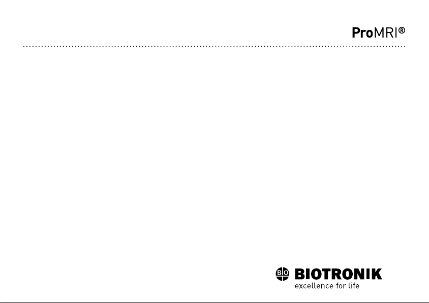
Order numbers Evia
The devices can be obtained as follows:
Device Order number:
HF-T 381534 381535
HF 381532 381533
uncoated
Order number:
coated
2 General Safety Instructions
Possible Medical Complications
General information on medical complications
Complications for patients and device systems generally recognized among practitioners also apply to BIOTRONIK devices.
•
Normal complications may include fluid accumulation within the device pocket,
infections, or tissue reactions. Primary sources of complication information include
current scientific and technological knowledge.
•
It is impossible to guarantee the efficacy of antitachycardia therapy, even if the
programs have proven successful during tests or subsequent electrophysiological
examinations. In rare cases the set parameters may become ineffective. In particular it cannot be excluded that tachyarrhythmias may be induced.
Skeletal myopotentials
Bipolar sensing and control of sensitivity are adapted by the device to the rate range of
intrinsic events so that skeletal myopotentials are usually not sensed. Skeletal myopotentials can nonetheless be classified as intrinsic events especially with a unipolar
configuration and/or very high sensitivity and, depending on the interference, may
cause inhibition or antiarrhythmia therapy.
Nerve and muscle stimulation
A device system consisting of a unipolar lead and an uncoated device may result in
undesirable pacing of the diaphragm in the case of an initial or permanent high setting
of the pulse amplitude.
•
BIOTRONIK also provides coated devices.
en • English
5
Page 7

Possible Technical Complications
Technical malfunctions
Technical device system malfuncti ons cannot entirely be excluded. Possible causes can
include the following:
•
Lead dislocation
•
Lead fracture
•
Insulation defects
•
Device component failures
•
Battery depletion
Possible Electromagnetic Complications
Electromagnetic interference (EMI)
Any device can be sensitive to interference, for example, when external signals are
sensed as intrinsic rhythm or if measurements prevent rate adaptation.
•
BIOTRONIK devices have been designed so that their susceptibility to EMI is
minimal.
•
Due to the intensity and variety of EMI, there is no guarantee for safety. It is generally assumed that EMI produces only minor symptoms in patients - if any.
•
Depending on the pacing mode and the type of interference, sources of interference
may lead to pulse inhibition or triggering, an increase in the sensor-dependent
pacing rate or asynchronous pacing.
•
Under unfavorable conditions, for example during diagnostic or therapeutic procedures, interference sources may induce such a high level of energy into the pacing
system that the cardiac tissue surrounding the lead tip is damaged.
Device behavior in case of EMI
In the case of electromagnetic interference or undesired myopotentials, the device
switches to asynchronous pacing for the duration of the time that the interference rate
is exceeded.
Static magnetic fields
The reed switch in the pacemaker starts to close at a field strength of 1.5 mT.
Possible Risks
Contraindicated procedures
The following procedures are contraindicated as they may cause harm to the patient or
damage the device and, as a result, put the system functionality at risk:
•
Therapeutic ultrasound: Harm to the patient via excess warming of body tissue
near the device system
•
Transcutaneous electrical nerve stimulation
•
Hyperbaric oxygen therapy
•
Applied pressures higher than normal pressure
Risky therapeutic and diagnostic procedures
If electrical current from an external source is conducted through the body for diagnostic or therapeutic purposes, then the device can be subjected to interference, which
can place the patient at risk.
Arrhythmia or ventricular fibrillation can be induced during diathermic procedures
such as electrocautery, HF ablation or HF surgery. For example, damaging heat levels
may arise during lithotripsy. Influences on the device are not always immediately clear.
If risky procedures cannot be avoided, the following should be observed at all times:
•
Electrically insulate the patient.
•
Switch the pacemaker function to asynchronous modes if needed.
•
Do not introduce energy near the device system.
•
Additionally check the peripheral pulse of the patient.
•
Monitor the patient during and after every intervention.
External defibrillation
The device is protected against the energy that is normally induced by external defibrillation. Nevertheless, any implanted device may be damaged by external defibrillation.
Specifically, the current induced in the implanted leads may result in necrotic tissue
formation close to the electrode/tissue interface. As a result, sensing properties and
pacing thresholds may change.
•
Place adhesive electrodes anterior-posterior or perpendicular to the axis formed
by the device to the heart at least 10 cm away from the device and from implanted
leads.
6
Page 8

Radiation therapy
The use of radiation therapy is contraindicated due to possible damage to the device
and the resulting impaired functional safety. If this type of therapy is to be administered
anyway, prior risk/benefit analysis is absolutely necessary. The complexity of influencing factors such as different sources of radiation, a variety of devices and therapy
conditions makes it impossible to issue directives that guarantee radiation therapy
without an impact on the device. The EN 45502 standard pertaining to active implantable medical devices requires the following measures during the administration of
therapeutic ionizing radiation:
•
Adhere to instructions for risky therapy and diagnosis procedures.
•
Shield device against radiation.
•
After applying radiation, double-check the device system to make sure it is functioning properly.
Note:
Please contact BIOTRONIK with questions during the risk/benefit analysis.
Magnetic resonance imaging
Magnetic resonance imaging is contraindicated due to the high frequency fields and the
associated magnetic flux density: damage or destruction of the device system by strong
magnetic interaction and damage to the patient by excessive warming of the body
tissue in the area surrounding the device system.
Under certain conditions and when maintaining mandatory measures to protect the
patient and device system, magnetic resonance imaging can be performed.
•
The ProMRI® manual – MR conditional device systems – contains detailed information on safely conducting an MR scan.
—
Download the digital manual from the web site:
www.biotronik.com/manuals/manualselection
—
Order the printed manual from BIOTRONIK.
•
Does approval as "MR-Conditional" apply in your country or region? Request
current information from BIOTRONIK.
en • English
Indications and Contraindications
Guidelines of cardiologic societies
Generally approved differential diagnostics methods, indications, and recommendations for pacemaker therapy apply to BIOTRONIK devices.
The guidelines provided by cardiology associations offer decisive information.
Indications
We recommend observing the indications published by the German Cardiac Society
(Deutsche Gesellschaft für Kardiologie, Herz- und Kreislaufforschung) and the ESC
(European Society of Cardiology). Likewise those published by the Heart Rhythm
Society (HRS), the American College of Cardiology (ACC), the American Heart Association (AHA) as well as other national cardiology associations.
Contraindications
No contraindications are known for the implantation of multifunctional triple-chamber
devices, provided differential diagnostics precedes implantation according to the
appropriate guidelines and no modes or parameter combinations are configured which
pose a risk to the patient.
Note:
The compatibility and effectiveness of parameter combinations must be
checked after programming.
Ambient Conditions
Temperature
Extremely low and high temperatures affect the service time of the battery in the
device.
•
The following temperatures are permitted for transport, storage, and use:
–10°C to 45°C
Storage location
•
Devices are not to be stored close to magnets or sources of electromagnetic interference.
Storage period
The duration of storage affects the service time of the battery of the device (see battery
data).
•
Please note the use by date.
7
3 Prior to Implantation
Page 9

Sterility
Delivery
The device and the accessories have been gas sterilized. Sterility is guaranteed only if
the plastic container and quality control seal have not been damaged.
Sterile container
The device and accessories are packaged respectively in two separately sealed plastic
containers. The inner plastic container is also sterile on the outside so that it can be
transferred in a sterile state during implantation.
Single use only
The device and the screwdriver are only intended for one-time use.
•
Do not use if package is damaged.
•
Do not resterilize.
•
Do not reuse.
Preparing the Implantation
Keeping an external defibrillator ready
In order to be able to respond to unforeseeable emergencies or possible device technical issues:
•
Keep an external defibrillator ready.
Have parts ready
The following parts that correspond to the requirements of the EC Directive 90/385/EEC
are required:
•
Device with screwdriver from BIOTRONIK
•
BIOTRONIK leads and lead introducer set
—
One unipolar or bipolar lead each for the atrium and for the right ventricle
—
One unipolar or bipolar lead each for the left ventricle (coronary sinus lead)
•
Adapters approved by BIOTRONIK for leads with different connections or leads
from other manufacturers
•
BIOTRONIK programmer and approved cables
•
External multi channel ECG device
•
Keep spare parts for all sterile components.
Unpacking the device
W
WARNING
Inadequate therapy due to defective device
If an unpacked device is dropped on a hard surface during handling, electronic parts
could be damaged.
•
Use a replacement device.
•
Send the damaged device to BIOTRONIK.
•
Peel off the sealing paper of the outer plastic container at the marked position in
the direction indicated by the arrow. The inner plastic container must not come into
contact with persons who have not sterilized their hands or gloves, or with nonsterile instruments.
•
Use the gripping tab on the inner plastic container to remove it from the outer
plastic container.
•
Peel off the sealing paper of the sterile inner plastic container at the marked position in the direction indicated by the arrow.
Note:
The device is disabled on delivery and can be implanted immediately after
unpacking without manual activation.
4 Implantation
Implanting
Implantation site
In general, the pacemaker is implanted on the right side subcutaneously or subpectorally, depending on the lead configuration as well as the anatomy of the patient.
Sequence
1 Shape the device pocket and prepare the vein.
2 Implant the leads and perform measurements.
3 Connect device and leads.
The device starts auto-initialization on its own.
8
Page 10

4 Insert the device.
DDDRV
IS-1
LV
RV
A
5 Guide the fixation suture through the opening in the header and fixate the
device in the prepared device pocket.
6 Close the device pocket.
7 Prior to testing and configuration, wait for the successful completion of
automatic device initialization.
Note:
If necessary, the device can also be programmed before or during auto-initial-
ization.
Applying the programming head
The programming head (PGH) features a diagram of the device. This is used to assist in
positioning the head to ensure proper telemetry.
•
Make sure the PGH is positioned correctly.
Connecting Pacemaker Leads
Connection options
BIOTRONIK pacemakers have been designed for use with leads with a unipolar or
bipolar IS-1 connection. For sensing and pacing, a unipolar or a bipolar lead can be
used:
•
Atrium: IS-1 unipolar or bipolar
•
Right and left ventricle: IS-1 unipolar or bipolar
Note:
Use only adapters approved by BIOTRONIK for leads with different connections.
•
If you have any questions concerning the compatibility of other manufacturers'
leads, please contact BIOTRONIK.
Connector allocation
Connection scheme for triple-chamber devices:
en • English
Preventing short circuits in the header
W
WARNING
Short circuit due to open lead connector ports
Connector ports in the header which are open and thus not electrolyte-proof may
cause undesired current flows to the body and penetration of body fluid into the
device.
•
Close unused connections with blind plugs.
Connecting the lead connector to the device
1 Disconnect stylets and stylet guides from the lead connector.
2•Connect the unipolar or bipolar IS-1 lead connector ventricle to RV.
•
Connect the unipolar or bipolar IS-1 lead connector atrium to A.
•
Connect the unipolar or bipolar IS-1 lead connector ventricle to LV.
3 Push the lead connector into the header without bending the conductor until the
connector tip becomes visible behind the set screw block.
4 If the lead connector cannot be inserted completely, the set screw may be
protruding into the cavity of the set screw block. Carefully loosen the set screw
without completely unscrewing it, so that it does not become tilted upon retightening.
5 Use the screwdriver to perpendicularly pierce through the slitting in the center of
the silicone plug until it reaches the set screw.
6 Turn the set screw clockwise until the torque control starts (audible clicking
sound).
7 Carefully withdraw the screwdriver without retracting the set screw.
•
When you withdraw the screwdriver, the silicone plug automatically seals the
lead connection safely.
9
Page 11

Keeping distance between leads
W
WARNING
Inadequate therapy
When leads are not spaced sufficiently apart or are positioned inappropriately, this
can lead to far-field sensing or insufficient defibrillation.
•
Tip and ring electrodes must not have contact with each other.
Auto-initialization
Auto-initialization begins automatically once the first connected lead is sensed.
Auto-initialization is terminated 10 minutes after connection of the first lead. If no other
program has been transferred in the meantime, the device subsequently works with
active automatic functions in the standard program.
Manual setting of the lead polarity or measurement of lead impedances is not necessary.
Note:
After auto-initialization, all parameters are activated as in the standard
program with the following exceptions:
•
DDD
•
The automatically determined lead configuration (unipolar or bipolar) is set.
Behavior during auto-initialization
•
During reprogramming:
Auto-initialization is canceled and the transferred program is immediately active.
•
During testing:
Auto-initialization will be continued upon completion of the test.
•
During transmission of a permanent program:
Auto-initialization is terminated and the transferred program is active.
Precautionary Measures while Programming
Checking the device system
•
After auto-initialization, perform a follow-up to see if the device system is functioning properly.
•
Perform a pacing threshold test to determine the pacing threshold.
Performing standard tests and monitoring the patient
Critical conditions can occur for the patient even during standard tests due to inadequate parameter settings or interrupted telemetry.
•
Ensure sufficient patient care even during tests.
•
After the threshold test, check to determine whether the threshold is clinically and
technically justifiable.
•
Continuously monitor the ECG and the patient's condition.
•
Cancel testing if necessary.
Cancelling telemetry
Programmer interference or interrupted telemetry during performance of temporary
programs (follow-up tests) can result in inadequate pacing of the patient. This is the
case if the programmer can no longer be operated due to a program error or
a defective touch screen and therefore the temporary program cannot be terminated.
Under these circumstances, it is helpful to cancel telemetry, in which case the device
automatically switches to the permanent program.
•
In the case of telemetry with PGH: lift the programming head by at least 30 cm.
•
Turn off possible sources of interference.
Avoiding critical parameter settings
No modes and parameter combinations that pose a risk to the patient should be set.
•
Prior to setting rate adaptation, determine the patient's capacity for strain.
•
Check compatibility and effectiveness of parameter combinations after making
settings.
Manually setting lead polarity
Due to the risk of an entrance/exit block, bipolar lead polarity (sensing/pacing) should
only be set if bipolar leads are implanted.
Recognizing lead failure
Automatic impedance measurement is always switched on.
•
Impedance values that indicate technical failure of a lead are documented in the
event list.
Setting triggered mode
Triggered modes perform pacing regardless of intrinsic cardiac events. To prevent
undersensing due to electromagnetic interference in special cases, a triggered mode
can be displayed.
10
Page 12

Setting sensing
Manually set parameters can be unsafe. For example, unsuitable far-field protection
may impede sensing of intrinsic pulses.
•
Use automatic sensitivity control.
Setting the sensitivity
A value set to < 2.5 mV/unipolar for device sensitivity may result in noise caused by
electromagnetic fields.
•
Therefore, it is recommended that a value of ≥ 2.5 mV/unipolar be set according to
paragraph 28.22.1 of the EN 45502-2-1 standard. Setting sensitivity values < 2.5
mV/unipolar requires explicit clinical need. Values like these may only be set and
maintained with physician supervision.
Preventing device-induced complications
BIOTRONIK devices feature several functions to prevent device-induced complications
to the greatest extent possible:
•
Measure the retrograde conduction time.
•
If the function is not yet automatically set: activate PMT protection.
•
Set the VA criterion.
Information on magnet response
Applying a magnet or the programming head can result in an unphysiological rhythm
change and asynchronous pacing. The magnet response is set as follows in the standard program of BIOTRONIK pacemakers:
•
Asynchronous:
For the duration of the magnet application – mode D00 (possibly V00 / A00) without
rate adaptation;
Magnet rate: 90 bpm
•
Automatic:
For 10 cycles – mode D00, subsequently mode DDD without rate adaptation;
Magnet rate: 10 cycles with 90 bpm, subsequently set basic rate
•
Synchronous:
Mode DDD without rate adaptation;
Magnet rate: set basic rate
Note:
See information pertaining to replacement indications for magnet behavior at
ERI.
Preventing conduction of atrial tachycardia
BIOTRONIK devices feature several functions to prevent conduction of atrial tachycardia to the ventricle(s):
•
Set mode switching for indicated patients.
•
Set the upper rate and the refractory periods to prevent abrupt ventricular rate
switching.
•
Prefer Wenckebach response and avoid 2:1 behavior.
•
Set all parameters so as to prevent constant changing between atrial and ventricular-controlled modes.
Phrenic nerve stimulation that cannot be terminated
With LV pacing, chronic phrenic nerve stimulation can in rare cases not be terminated
by reprogramming the available left ventricular pacing configurations or by other
measures.
•
Possibly set a right ventricular mode both in the permanent program and for
Mode Switching.
Avoiding risks in the case of exclusive LV pacing
Lead dislodgement in the case of exclusive left ventricular pacing could pose the
following risks: loss of ventricular pacing as well as induction of atrial arrhythmia.
•
Consider sensing and pacing parameters with reference to loss of therapy.
•
Exclusive LV pacing is not recommended for patients who depend on the device.
•
Take possible interruption of automatic Active Capture Control into consideration.
•
In the case of follow-ups and threshold tests, take loss of synchronized ventricular
pacing into consideration.
If an ICD is implanted at the same time, do not permit unipolar pacing
If an ICD is implanted in addition to a pacemaker and a lead fail ure occurs, it is possible
to switch to unipolar pacing after resetting the pacemaker or using the automatic lead
check. As a result, the ICD could falsely inhibit or trigger tachyarrhythmia therapy
activity.
•
Unipolar leads are not permitted in this configuration.
Consider power consumption and service time.
The pacemaker permits programming of high pulse amplitudes with long pulse widths
at high rates to be able to adequately treat even rare diagnoses. In combination with
low lead impedance, this results in a very high level of power consumption.
en • English
11
Page 13

•
When programming large parameter values, take into account that the battery
depletion indicator ERI will be reached very early because the service time of the
battery may be reduced to less than 1 year.
5 After Implantation
Follow-up
Follow-up intervals
Follow-ups must be performed at regular, agreed intervals.
•
Following the lead ingrowth phase, approximately 3 months after implantation,
the first follow-up should be carried out by the physician using the programmer
(in-office follow-up).
•
The next in-office follow-up should be carried out once a year and no later than
12 months after the last in-office follow-up.
Follow-up with BIOTRONIK Home Monitoring®
Monitoring using the Home Monitoring function does not serve to replace regular inoffice appointments with the physician required for other medical reasons.
Follow-up supported by Home Monitoring can be used to functionally replace in-office
follow-up under the following conditions:
•
The patient was informed that the physician must be contacted if symptoms worsen
or if new symptoms arise despite of the use of the Home Monitoring function.
•
Device messages are transmitted regularly.
•
The physician decides whether the data transmitted via Home Monitoring with
regard to the patient's clinical condition as well as the technical state of the device
system are sufficient. If not, an in-office follow-up has to be carried out.
Possible early detection due to information gained via Home Monitoring may necessitate an additional in-office follow-up. For example, the data may indicate at an early
stage lead problems or a foreseeable end of service time (ERI). Furthermore, the data
could provide indications of previously unrecognized arrhythmias or modification of the
therapy by reprogramming the device.
Follow-up with the programmer
Use the following procedure for in-house follow-up:
1 Record and evaluate the external ECG.
2 Check the sensing and pacing function.
3 Interrogate the device.
4 Evaluate the status and automatically measured follow-up data.
5 Possibly evaluate statistics and IEGM recording.
6 Manually perform standard tests if necessary.
7 Possibly customize program functions and parameters.
8 Transmit the program permanently to the device.
9 Print and document follow-up data (print report).
10 Finish the follow-up for this patient.
Notes for the Physician
Patient ID card
A patient ID card is included in the delivery.
•
Provide the patient with the patient ID card.
•
Request that patients contact the physician in case of uncertainties.
Prohibitive signs
Places with prohibitive signs must be avoided.
•
Draw the patient's attention to prohibitory signs.
Possible sources of interference
Electromagnetic interference should be avoided in daily activities. Sources of interference should not be brought into close proximity with the device.
•
Draw the patient's attention to special household appliances, security checkpoints,
anti-theft alarm systems, strong electromagnetic fields, cell phones, and transmitters among other things.
•
Request patients to do the following:
—
Use cell phones on the side of their body that is opposite of the device.
—
Keep the cell phone at least 15 cm away from the device both during use and
when stowing.
12
Page 14

Magnet application by patients
If patients are performing their own magnet application, the synchronous magnet
response has to have been programmed. Patients should also know the following:
•
When may the magnet be used?
In cases of severe dizziness and indisposition.
•
How long is the magnet placed on the pacemaker?
1 to 2 s.
•
What happens when the magnet is applied?
The IEGM of the last 10 seconds is stored.
•
What has to happen after magnet application?
The patient has to contact the physician for a follow-up.
Replacement Indications
Pacemaker operational status indications
The time span from the beginning of service (BOS) to elective replacement indication
(ERI) is determined by, among others, the following:
•
Battery capacity
•
Lead impedance
•
Pacing program
•
Pacing to inhibition ratio
•
Pacemaker circuit properties
The following are the defined pacemaker operational statuses:
BOS
Beginning of Service Battery is in good condition; normal follow-up.
ERI
Elective Replacement
Indication
EOS
End of Service End of service time with regular pacemaker activity.
ERI activation
ERI detection is automatically activated after the following events:
•
Successful auto-initialization
•
Storage for longer than 24 months
The replacement time has been reached.
The pacemaker must be replaced.
ERI display
ERI is displayed as follows:
•
On the programmer after interrogation of the pacemaker
•
By a defined decrease in the basic rate as well as the magnet rate
Change of the mode with ERI
From triple-chamber modes, the pacemaker switches to dual-chamber pacing. This
replacement depends on the programmed mode and is displayed on the programmer.
Deactivated functions with ERI
The following functions are deactivated:
•
Atrial pacing
•
Night program
•
Rate adaptation
•
Atrial and ventricular capture control
•
Rate fading
•
Atrial overdrive pacing
•
IEGM recordings
•
Statistics
•
Home Monitoring
•
Rate hysteresis
•
Ventricular pacing suppression
Rate decrease
The decrease of basic rate and magnet rate is defined as follows:
•
In the following modes, the pacing rate decreases by 11%:
DDD(R); DDT(R); DOO(R); VDD(R); VDI(R); VVI(R); VVT(R); AAI(R); AAT(R); AOO(R)
•
In the modes DDI(R) and DVI(R), only the VA interval is extended by 11%. This
reduces the pacing rate by 4.5 to 11% depending on the configured AV delay.
en • English
13
Page 15
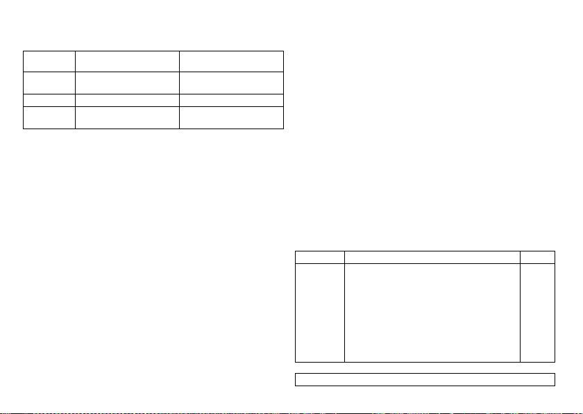
Magnet response at ERI
After reaching ERI pacing is performed as follows after applying the magnet or
programming head:
Magnet
response
Automatically Asynchronous with 80 bpm Synchronous with basic rate
Asynchronous Asynchronous with 80 bpm Asynchronous with 80 bpm
Synchronous Synchronous with basic rate
Expected service time after ERI
•
The information is based on a lead impedance of 500 ohm at 100% pacing and the
data of the battery manufacturer.
•
Parameter with high pacing energy:
110 bpm; 4.6 V; 1.5 ms; 500 ohm
•
Parameters with low pacing energy:
30 bpm; 0.2 V; 0.1 ms; 500 ohm
•
Interval from ERI to EOS with triple-chamber device is DDD(R) mode in the standard program and both with high and low pacing energy:
—
—
Cycles 1 to 10: After 10th cycle:
reduced by 4.5 to 11%
Mean value: 8 months
Minimum value: 6 months
reduced by 4.5 to 11%
Synchronous with basic rate
reduced by 4.5 to 11%
Explantation and Device Replacement
Explantation
•
Disconnect the leads from the header.
•
Remove the device and, if necessary, also remove the leads using state-of-the-art
technology.
•
Explants are biologically contaminated and must be disposed safely due to risk of
infection.
Device replacement
The following applies to leads from a previous device that are intended for further use:
•
Check the leads prior to connecting to the new device.
If, upon replacing the device, already implanted leads are no longer used but left in the
patient, then an additional uncontrolled current path to the heart can result.
•
Insulate connections that are not used.
Basic principles
•
The device must not be resterilized and reused.
Cremation
Devices must not be cremated.
•
Explant the device before the cremation of a deceased patient.
Disposal
BIOTRONIK takes back used products for the purpose of environmentally safe disposal.
•
Clean the explant with an at least 1% sodium hypochlorite solution.
•
Rinse off with water.
•
Fill out the explantation form and send it to BIOTRONIK together with the cleaned
device.
6 Parameters
Modes
Evia family
The mode setting depends on the individual diagnosis:
Device type Mode Standard
HF(-T)
Note:
•
DDD-CLS; VVI-CLS
•
DDDR; DDIR; DVIR; DOOR
VDDR; VDIR; VVIR; VVTR; VOOR
AAIR; AATR; AOOR
•
DDD; DDT; DDI; DVI; DOO
VDD; VDI; VVI; VVT; VOO
AAI; AAT; AOO
•
DDD-ADI; DDDR-ADIR
•
OFF
Home Monitoring is possible in all modes.
DDDR
14
Page 16

Timing: Triple-Chamber
Basic rate day/night
Parameter Range of values Standard
Basic rate 30 ... (1) ... 88 ... (2) ... 122 ... (3) ... 140
Night rate OFF
Night begins 00:00 ... (10 min) ... 11:50 PM hh:mm 10:00 PM hh:mm
Night ends 00:00 ... (10 min) ... 11:50 PM hh:mm 6:00 AM hh:mm
Rate hysteresis
Parameter Range of values Standard
Rate hysteresis OFF
Repetitive hysteresis OFF; 1 ... (1) ... 15 5
Scan hysteresis OFF; 1 ... (1) ... 15 5
AV delay, VV delay
Parameter Range of values Standard
AV delay Low; medium; high; fixed; individual Low
Sense compensation OFF
AV safety interval 100 ms 100 ms
VV delay after Vp 0 ... (5) ... 80; 90; 100 ms 0
en • English
... (5) ... 200 bpm
30 ... (1) ... 88 ... (2) ... 122 ... (3) ... 140
... (5) ... 200 bpm
-5 ... (-5) ... -90 bpm
15 ... (5) ... 350 ms
(in 6 rate ranges)
-10 ... (5) ... -120 ms
60 bpm
OFF
OFF
150 to 120 ms
-45 ms
AV hystereses
Parameter Range of values Standard
AV hysteresis OFF
All modes except for
negative ones:
AV repetitive hysteresis
Negative modes:
AV repetitive hysteresis
Ventricular pacing suppression
Parameter Range of values Standard
Vp suppression OFF; ON OFF
Pacing suppression after consecutive
ventricular sensing
Pacing supported after X-out-of-8 cycles 1; 2; 3; 4 3
Upper rate
Parameter Range of values Standard
Upper rate 90 ... (10) ... 200 bpm 130 bpm
Upper rate, atrium OFF
Mode switching
Parameter Range of values Standard
Mode switching OFF; ON ON
Intervention rate 100 ... (10) ... 250 bpm 160 bpm
Switch to (mode) DDI; DDI(R) when permanent DDD(R)
Onset criterion 3 ... (1) ... 8 5
Resolution criterion 3 ... (1) ... 8 5
Negative, low; medium; high; IRSplus
OFF
1 ... (1) ... 10
OFF
1 ... (1) ... 10 ... (5) ... 100 ... (10) ... 180
1 ... (1) ... 8 6
240 bpm
VDI; VDI(R) when permanent VDD(R)
15
OFF
OFF
OFF
240 bpm
DDI(R)
VDI(R)
Page 17

Parameter Range of values Standard
Change of the basic rate
with mode switching
Rate stabilization OFF; ON OFF
Refractory periods
Parameter Range of values Standard
Atrial refractory period AUTO AUTO
Atrial refractory period in
the modes AAI(R); AAT(R);
DDT
PVARP AU TO
PVARP after PVC PVARP + 150 ms (max: 600 ms) is
Ventricular refractory
period
Blanking periods
Parameter Range of values Standard
Far-field protection after Vs 100 ... (10) ... 220 ms 100 ms
Far-field protection after Vp 100 ... (10) ... 220 ms 150 ms
Ventricular blanking period
after Ap
PMT protection
Parameter Range of values Standard
PMT detection/termination OFF; ON ON
VA criterion 250 ... (10) ... 500 ms 350 ms
OFF
+5 ... (5) ... +30 bpm
300 ... (25) ... 775 ms 350 ms
175 ... (5) ... 600 ms
automatically programmed
200 ... (25) ... 500 ms 250 ms
30 ... (5) ... 70 ms 30 ms
+10 bpm
AUTO
400 ms
Pacing and Sensing: Triple-Chamber
Pulse amplitude and pulse width
Parameter Range of values Standard
Pulse amplitude A 0.2 ... (0.1) ... 6.0 ... (0.5) ... 7.5 V 3.0 V
Pulse width A 0.1 ...(0.1) ... 0.5; 0.75; 1.0; 1.25; 1.5 ms 0.4 ms
RV/LV pulse amplitude 0.2 ... (0.1) ... 6.0 ... (0.5) ... 7.5 V 3.0 V
RV/LV pulse width 0.1 ... (0.1) 0.5; 0.75; 1.0; 1.25; 1.5 ms 0.4 ms
Sensitivity
Parameter Range of values Standard
Sensitivity A AUTO
RV sensitivity AUTO
LV sensitivity OFF; AUTO
Atrial capture control
Parameter Range of values Standard
Atrial capture control ATM (monitoring only)
Min. amplitude 0.5 ... (0.1) ... 4.8 V 1.0 V
Threshold test start 2.4; 3.0; 3.6; 4.2; 4.8 V 3.0 V
Safety margin 0.5 ... (0.1) ... 1.2 V 1.0 V
Search type Interval; time of day Time of day
Interval 0.1; 0.3; 1; 3; 6; 12; 24 h 24 h
Time of day 00:00 ... (10 min) ... 23:50 02:00 hh:mm
0.1 ... (0.1) ... 1.5 ... (0.5) ... 7.5 mV
0.5 ... (0.5) ... 7.5 mV
0.5 ... (0.5) ... 7.5 mV
ON; OFF
AUTO
AUTO
AUTO
ON
16
Page 18

Ventricular capture control
Parameter Range of values Standard
A/RV/LV capture control ATM (monitoring only)
Min. amplitude 0.7 V 0.7 V
Threshold test start 2.4; 3.0; 3.6; 4.2; 4.8 V 3.0 V
RV safety margin 0.3 ... (0.1) ... 1.2 V 1.0 V
LV safety margin 1.0; 1.2 V 1.0 V
Search type Interval; time of day Time of day
Interval 0.1; 0.3; 1; 3; 6; 12; 24 h 24 h
Time of day 00:00 ... (10 min) ... 23:50 2:00 hh:mm
Atrial overdrive pacing
Parameter Range of values Standard
Atrial overdrive pacing ON; OFF OFF
Lead configuration
Parameter Range of values Standard
Sensing polarity A and RV/LV Unipolar; bipolar Unipolar
Pacing polarity A and RV Unipolar; bipolar Unipolar
Pacing polarity LV LV tip -> LV ring
ON; OFF
LV tip -> RV ring
LV ring -> LV tip
LV ring -> RV ring
LV tip -> housing
LV ring -> housing
ON
LV tip –> housing
IEGM recordings
Parameter Range of values Standard
IEGM recordings 20 (quantity); each max. 10 s
Types of IEGM recordings High atrial rate (HAR) HAR
IEGM recording prior to event 0; 25; 50; 75; 100% 75%
IEGM signal Filtered; unfiltered Filtered
Rates for statistics
Parameter Range of values Standard
High atrial rate (HAR) 100 ... (5) ... 250 bpm
High ventricular rate (HVR) 150 ... (5) ... 200 bpm
HVR counter 4; 8; 12; 16 8
Mode switching
High ventricular rate (HVR) ON
Patient-triggered OFF
600; 572 ... 245; 240 ms
400; 387 ... 308; 300 ms
200 bpm
300 ms
180 bpm
333 ms
Rate Adaptation
Rate adaptation via Closed Loop Stimulation
CLS modes:
Parameter Range of values Standard
Max. CLS rate 80 ... (5) ... 160 bpm 120 bpm
CLS response Very low; low; medium; high; very high Medium
Resting rate control OFF; +10 ... (10) ... +50 bpm +20 bpm
Vp required Yes; no Yes
en • English
17
Page 19

Rate adaptation via accelerometer
R modes:
Parameter Range of values Standard
Sensor gain 1 ... 23 4
Max. activity rate 80 ... (5) ... 180 bpm 120 bpm
Automatic gain OFF; ON ON
Sensor threshold Very low; low; medium; high; very high Medium
Rate increase 1 ... (1) ... 10 bpm/cycle 4 bpm/cycle
Rate decrease 0.1; 0.2; 0.5; 1.0 bpm/cycle 0.5 bpm/cycle
Rate fading OFF; ON OFF
Preset programs: Triple-Chamber
Standard and safe program
Only the auto-initialization function is activated as a factory setting. All the other functions of the standard program are deactivated.
Parameter Standard program Safe program
Mode (after auto-initialization: DDD) DDDR VVI
Basic rate 60 bpm 70 bpm
Night program OFF OFF
Rate hysteresis OFF OFF
Upper rate 130 bpm —
Dynamic AV delay Low —
AV hysteresis OFF —
Sense compensation -45 ms —
AV Safety Delay 100 ms —
VV delay — —
LV T-wave protection ON ON
Far-field protection after Vs 100 ms —
Far-field protection after Vp 150 ms —
Ventricular blanking period after Ap 30 ms —
Parameter Standard program Safe program
PMT protection ON —
VA criterion 350 ms —
Magnet response AUTO AUTO
Pulse amplitude A 3.0 V —
Pulse amplitude RV, LV 3.0 V 4.8 V
Pulse width A 0.4 ms —
Pulse width RV, LV 0.4 ms 1.0 ms
Sensitivity A AUTO —
Sensitivity RV, LV AUTO 2.5 mV
Refractory period A AUTO —
Refractory period RV 250 ms 300 ms
Refractory period LV 200 ms 200 ms
Mode switching ON —
Onset criterion 5-out-of 8 —
Resolution criterion 5-out-of 8 —
Intervention rate 160 bpm —
Switches to DDIR —
Basic rate with mode switching +10 bpm —
Rate stabilization with mode switching OFF —
2:1 lock-in protection ON —
PVARP AUTO —
PVARP after PVC 400 ms —
Lead configuration, automatically determined and set:
Pacing polarity A/RV/LV Unipolar Unipolar
Sensing polarity A/RV/LV Unipolar Unipolar
Automatic lead check A/RV/LV ON —
Active capture control A/RV/LV ON OFF
Atrial overdrive pacing OFF —
18
Page 20

Parameter Standard program Safe program
Vp suppression OFF —
IEGM recording (HAR, HVR) ON OFF
Home Monitoring OFF OFF
Tolerances of Parameter Values
Triple-chamber
Parameter Range of values Tolerance
Basic rate 30 ... 100 bpm +/-1.5 bpm
Basic interval 1000 ms +/-20 ms
Magnet rate 90 bpm +/-1.5 bpm
Magnet interval 664 ms +/-20 ms
AV delay 15 ... 350 ms +20/-5 ms
Pulse amplitude A/RV/LV 0.2 V +/-0.10 V
Pulse width A/RV/LV 0.1 ... 0.4 ms +/-0.04 ms
Sensitivity A
45502-2-1 triangle pulse
RV/LV sensitivity
45502-2-1 triangle pulse
Refractory period A 300 ... 775 ms +10/-30 ms
RV/LV refractory period 200 ... 500 ms +10/-30 ms
PVARP 175 ... 600 ms +10/-30 ms
PVARP after PVC 325 ... 600 ms +10/-30 ms
en • English
102 ... 195 bpm +/-2.0 bpm
200 bpm +0.0/-3.0 bpm
0.3 ... 7.5 V +20/-25%
0.5 ... 1.0 ms +/-0.10 ms
1.25 ... 1.5 ms +/-0.15 ms
0.1 mV +0.2/-0.1 mV
0.2 ... 0.5 mV +/-0.1 mV
0.6 ... 7.5 mV +/-20%
0.5 mV +/-50%
1.0 ... 7.5 mV +/-20%
Parameter Range of values Tolerance
Max. activity rate 80 ... 100 bpm +/-1.5 bpm
Upper rate 90 ... 190 bpm +/-2.0 bpm
High rate protection 200 bpm +20/-0 bpm
Lead impedance 100 ... 200 Ω: +/-50 Ω:
105 ... 180 bpm +/-2.0 bpm
200 bpm +0/-2.0 bpm
201 ... 2500 Ω: +/-25%
7 Technical Data
Mechanical Characteristics
Measurements for the housing
Device W x H x D [mm]
HF-T 53 x 49 x 6.5 14 27
HF 53 x 49 x 6.5 14 27
Note:
D = housing without header
X-ray identification
BIO SF
Materials in contact with body tissue
•
Housing: Titanium
•
Header: Epoxy resin
•
Coating, if applicable: Silicone
Volume [cm3]
19
Mass [g]
Page 21

Electrical Characteristics
Components and input values
Electrical characteristics determined at 37°C, 500 Ω:
Circuit Hybrid electronics with VLSI-CMOS chip
Input impedance > 10 kOhm
Pulse form Biphasic, asymmetric
Polarity Cathodic
Housing shape
The device housing has the following shape:
Device type Triple-chamber
Uncoated Flattened ellipsoid
Coated
Electrically conductive surface
The device housing has the following surface:
Device type Triple-chamber
Uncoated [cm2]
Coated [cm2]
Pulse form
The pacing pulse has the following form:
Resistance to interference
All variants of BIOTRONIK devices comply with the requirements of prEN 45502-2-1:
2006, § 27.5.1 at the highest sensitivity.
33
7
The pulse amplitude reaches its maximum
value at the beginning of the pulse (Ua).
With increasing pacing duration (tb), the pulse
amplitude is reduced dependent on the pacing
impedance.
Telemetry
Telemetry data for Home Monitoring:
Nominal carrier frequency Maximum power of transmission
403.62 MHz < 25 µW
Industry Canada
Telemetry data
•
This device must not interfere with stations operating in the 400.150 - 406.000 MHz
band in the meteorological aids, meteorological-satellite, and earth explorationsatellite services and must accept any interference received, including interference
that may cause undesired operation.
•
This device will be registered with Industry Canada under the following number:
IC: 4708A-PRIMUS
•
The code IC in front of the certification/registration number only indicates that the
technical requirements for Industry Canada are met.
-16 dBm
Battery Data
Battery characteristics
The following data is provided by the manufacturers:
Manufacturer GREATBATCH, INC.
Battery type GB 2596 LiS 3150M
System Ag/SVO/CFx
Device type HF(-T) HF(-T)
Battery voltage at BOS 3.0 V 3.1 V
Open-circuit voltage 3.0 V 3.1 V
Nominal capacity 1.3 Ah 1.2 Ah
Remaining capacity at ERI 0.2 Ah 0.2 Ah
Usable capacity until EOS 1.1 Ah 1.0 Ah
Clarence, NY 14031
QMR®
LITRONIK GmbH
01796 Pirna, Germany
LiMn0
2
20
Page 22

Power consumption
•
BOS, inhibited: 7 µA
•
BOS, 100% pacing: 18 µA
Average service time
Average service times are precalculated using the battery manufacturer's technical
specifications, a basic rate of 60 bpm in DDDR mode and the setting of different pulse
amplitudes and lead impedances. These apply to Evia HF as well as Evia HF-T.
Service times triple-chamber
For triple-chamber devices, the following times (in years) result:
Amplitude
Pulse width:
0.4 ms
A: 2.0 V
RV: 2.2 V
LV: 2.4 V
A: 2.5 V
RV: 2.5 V
LV: 2.5 V
A: 2.5 V
RV: 2.5 V
LV: 3.5 V
A: 3.0 V
RV: 3.0 V
LV: 3.0 V
Atrial pacing,
Biventricular
pacing 100%
0% 10.6 11.1 12.2
30% 10.2 10.8 11.9
50% 9.9 10.4 11.8
100% 9.4 9.8 11.3
0% 10.3 10.8 12.0
30% 9.8 10.4 11.7
50% 9.6 10.1 11.4
100% 9.0 9.4 10.9
0% 8.8 9.8 10.8
30% 8.5 9.3 10.6
50% 8.3 9.1 10.4
100% 7.8 8.6 10.0
0% 8.8 9.4 10.8
30% 8.3 8.8 10.3
50% 7.9 8.5 10.1
100% 7.3 7.8 9.5
Impedance:
500 ohm
A+RV+LV
Impedance:
500 ohm A+RV,
800 ohm LV
Impedance:
1000 ohm
A+RV+ LV
Amplitude
Pulse width:
0.4 ms
A: 3.5 V
RV: 3.5 V
LV: 5.0 V
Shortening of the service time after long storage period
Depending on the storage period, the service time from the beginning of service BOS to
the replacement time ERI decreases as follows:
•
•
Atrial pacing,
Biventricular
pacing 100%
0 % 5.3 6.4 7.7
30% 5.1 6.1 7.3
50% 4.9 5.8 7.2
100% 4.6 5.3 6.8
After 1 year by three months
After 1.5 years by four months
Impedance:
500 ohm
A+RV+LV
Impedance:
500 ohm A+RV,
800 ohm LV
Impedance:
1000 ohm
A+RV+ LV
en • English
21
Page 23

Legend for the Label
STERILIZE
2
NON
STERILE
The label icons symbolize the following:
Manufacturing date Use by
Temperature limit Order number
Serial number Product identification
CE mark
Contents Follow the instructions for
Sterilized with ethylene oxide
Do not resterilize Single use only.
number
use
Do not re-use!
Uncoated device: NBG code and compatible leads
Example
Coated device: NBG code and compatible
leads
Example
Screwdriver
Header
Example
Bipolar IS-1 connector
Unipolar IS-1 connector
Do not use if packaging is
damaged
Non-sterile
Transmitter with non-ionizing radiation at designated frequency
MR conditional: Patients having a device system implanted whose
components are labeled with this symbol on the packaging can be
examined using an MR scan under precisely defined conditions.
22
Page 24

cs • Česky
Popis výrobku . . . . . . . . . . . . . . . . . . . . . . . . . . . . . . . . . . . . . . . . . . . . . . . . . . . . . . . . . . 23
Zamýšlené lékařské použití . . . . . . . . . . . . . . . . . . . . . . . . . . . . . . . . . . . . . . . . . 23
Přehled systému. . . . . . . . . . . . . . . . . . . . . . . . . . . . . . . . . . . . . . . . . . . . . . . . . . 23
Varianty implantátu a kódy NBG . . . . . . . . . . . . . . . . . . . . . . . . . . . . . . . . . . . . . 25
Diagnostické a terapeutické funkce . . . . . . . . . . . . . . . . . . . . . . . . . . . . . . . . . . 25
Obsah balení . . . . . . . . . . . . . . . . . . . . . . . . . . . . . . . . . . . . . . . . . . . . . . . . . . . . . 26
Všeobecné bezpečnostní pokyny . . . . . . . . . . . . . . . . . . . . . . . . . . . . . . . . . . . . . . . . . . . 26
Možné zdravotní komplikace . . . . . . . . . . . . . . . . . . . . . . . . . . . . . . . . . . . . . . . . 26
Možné technické komplikace. . . . . . . . . . . . . . . . . . . . . . . . . . . . . . . . . . . . . . . . 27
Možné elektromagnetické komplikace. . . . . . . . . . . . . . . . . . . . . . . . . . . . . . . . 27
Možná rizika . . . . . . . . . . . . . . . . . . . . . . . . . . . . . . . . . . . . . . . . . . . . . . . . . . . . . 27
Před implantací . . . . . . . . . . . . . . . . . . . . . . . . . . . . . . . . . . . . . . . . . . . . . . . . . . . . . . . . . 28
Indikace a kontraindikace . . . . . . . . . . . . . . . . . . . . . . . . . . . . . . . . . . . . . . . . . . 28
Okolní podmínky . . . . . . . . . . . . . . . . . . . . . . . . . . . . . . . . . . . . . . . . . . . . . . . . . . 28
Sterilita . . . . . . . . . . . . . . . . . . . . . . . . . . . . . . . . . . . . . . . . . . . . . . . . . . . . . . . . . 28
Příprava implantace . . . . . . . . . . . . . . . . . . . . . . . . . . . . . . . . . . . . . . . . . . . . . . . 29
Implantace . . . . . . . . . . . . . . . . . . . . . . . . . . . . . . . . . . . . . . . . . . . . . . . . . . . . . . . . . . . . . 29
Implantace. . . . . . . . . . . . . . . . . . . . . . . . . . . . . . . . . . . . . . . . . . . . . . . . . . . . . . . 29
Připojení elektrod kardiostimulátoru . . . . . . . . . . . . . . . . . . . . . . . . . . . . . . . . . 30
Bezpečnostní opatření při programování . . . . . . . . . . . . . . . . . . . . . . . . . . . . . . 31
Po implantaci . . . . . . . . . . . . . . . . . . . . . . . . . . . . . . . . . . . . . . . . . . . . . . . . . . . . . . . . . . 32
Follow-up . . . . . . . . . . . . . . . . . . . . . . . . . . . . . . . . . . . . . . . . . . . . . . . . . . . . . . . 32
Poznámky pro lékaře . . . . . . . . . . . . . . . . . . . . . . . . . . . . . . . . . . . . . . . . . . . . . . 33
Indikace pro výměnu. . . . . . . . . . . . . . . . . . . . . . . . . . . . . . . . . . . . . . . . . . . . . . . 34
Explantace a výměna implantátu. . . . . . . . . . . . . . . . . . . . . . . . . . . . . . . . . . . . . 35
Parametr . . . . . . . . . . . . . . . . . . . . . . . . . . . . . . . . . . . . . . . . . . . . . . . . . . . . . . . . . . . . . . 35
Režimy . . . . . . . . . . . . . . . . . . . . . . . . . . . . . . . . . . . . . . . . . . . . . . . . . . . . . . . . . . 35
Časování - 3dutinový . . . . . . . . . . . . . . . . . . . . . . . . . . . . . . . . . . . . . . . . . . . . . . 35
Stimulace a snímání - 3dutinový . . . . . . . . . . . . . . . . . . . . . . . . . . . . . . . . . . . . 37
Přizpůsobení frekvence . . . . . . . . . . . . . . . . . . . . . . . . . . . . . . . . . . . . . . . . . . . . 38
Předvolené programy - třídutinové . . . . . . . . . . . . . . . . . . . . . . . . . . . . . . . . . . 39
Tolerance hodnot parametrů. . . . . . . . . . . . . . . . . . . . . . . . . . . . . . . . . . . . . . . . 40
Obsah
Technické parametry . . . . . . . . . . . . . . . . . . . . . . . . . . . . . . . . . . . . . . . . . . . . . . . . . . . . .40
Mechanické parametry. . . . . . . . . . . . . . . . . . . . . . . . . . . . . . . . . . . . . . . . . . . . . 40
Elektrické parametry . . . . . . . . . . . . . . . . . . . . . . . . . . . . . . . . . . . . . . . . . . . . . . 40
Údaje o baterii . . . . . . . . . . . . . . . . . . . . . . . . . . . . . . . . . . . . . . . . . . . . . . . . . . . . 41
Vysvětlivky ke štítku . . . . . . . . . . . . . . . . . . . . . . . . . . . . . . . . . . . . . . . . . . . . . . . 43
1 Popis výrobku
Zamýšlené lékařské použití
Použití v souladu s ustanovením
Evia je název rodiny implantovatelných kardiostimulátorů, které mohou být implantovány u všech indikací bradykardických poruch srdečního rytmu. Primární cíl léčby je
zlepšit klinicky se projevující symptomy pacientů. Implantace kardiostimulátoru je
symptomatická léčba, která má následující cíl:
•
kompenzace bradykardie pomocí síňové, komorové nebo AV sekvenční stimulace;
•
resynchronizace komorové kontrakce pomocí biventrikulární stimulace.
Diagnóza a způsoby léčby
Srdeční rytmus je automaticky kontrolován a bradykardické arytmie jsou ošetřovány.
Skupina Evia zahrnuje všechny hlavní terapeutické kardiologické a elektrofyziologické
přístupy. BIOTRONIK Home Monitoring® umožňuje lékařům řízení léčby kdykoliv.
Předpokládané odborné znalosti
Mimo medicínského základu jsou třeba podrobné znalosti funkcí a podmínek použití
implantátového systému.
•
Pouze lékařští odborníci s těmito zvláštními znalostmi mohou implantáty používat
v souladu s ustanovením.
•
Nejsou-li tyto znalosti k dispozici, musí být uživatel proškolen.
Přehled systému
Skupina implantátů
Evia HF a Evia HF-T jsou třídutinové implantáty a patří do skupiny produktů Evia.
Ne v každé zemi jsou dostupné všechny typy implantátů.
cs • Česky
23
Page 25

Součásti
Součásti implantátového systému jsou následující:
•
implantát s konektory pro uni- nebo bipolární snímání a stimulaci;
•
vhodné elektrody, adaptér a povolené příslušenství;
•
programátor,
•
aktuální softwarová verze.
Implantát
Z vnější strany svařené a tak hermeticky utěsněné pouzdro implantátu je vyrobeno
z biologicky kompatibilního titanu. Elipsovitý tvar usnadňuje vrůstání do oblasti pektorálního svalu. Pouzdro slouží jako protipól při unipolární konfiguraci elektrody. Pro
zabránění trhání svalu v blízkosti implantovaného kardiostimulátoru při unipolární
stimulaci nabízí BIOTRONIK implantát potažený silikonem. Značení poskytuje informace o typu implantátu a uspořádání připojení.
Elektrody
Elektrody jsou vyrobeny z biokompatibilního silikonu. Mohou být flexibilně ovládány,
jsou dlouhodobě stabilní a jsou vybaveny aktivní nebo pasivní fixací. Jsou implantovány
pomocí soupravy pro zavedení elektrody. Některé elektrody jsou potaženy polyuretanem, který zvyšuje kluzné vlastnosti elektrody. Steroidní povlak elektrod snižuje
výskyt zánětlivého procesu. Fraktální design elektrod poskytuje nízké stimulační prahy,
vysokou impedanci a nízké riziko oversensingu.
Programátor
Pomocí přenosného programátoru je aktuální softwarová verze přenášena na implantát. Programátor kromě toho slouží k ověřování a uložení dat do paměti z implantátu.
A funguje jako monitor EKG a IEGM.
Upozornění :
EKG zobrazené pomocí přístroje nesmí být použito k diagnostickým
účelům, protože nesplňuje všechny požadavky normy pro diagnostické EKG přístroje
(IEC 60601-2-25).
Programátor komunikuje s implantátem přes programovací hlavici. Má k dispozici TFT
dotykovou obrazovku s barevným displejem, na kterém jsou současně zobrazeny funkce
EKG, IEGM a markru. Programátor má mezi dalšími tyto funkce:
•
provedení všech testů během prezenčního follow-up,
•
zobrazení a tisk IEGM v reálném čase a uložených IEGM s popisovanými markery,
•
zjištění stimulačního prahu.
BIOTRONIK Home Monitoring
Kromě účinné stimulační terapie je k dispozici kompletní terapeutický systém
BIOTRONIK:
•
Při domácím monitoringu jsou diagnostické a terapeutické informace i technické
parametry implantátu automaticky a bezdrátově přenášeny prostřednictvím antény
v rozdělovači implantátu na stacionární nebo mobilní přístroj pro pacienty.
Z přístroje pro pacienty jsou data kódována a přenášena přes mobilní vysílací síť do
servisního centra BIOTRONIK.
•
Obdržená data jsou dekódována a vyhodnocena; každý lékař může u každého
pacienta individuálně nastavit kritéria pro vyhodnocení a může nastavit, kdy má být
informován e-mailem, sms nebo faxem.
•
Výsledky vyhodnocení jsou pro ošetřující lékaře přehledně znázorněny na chráněné
internetové platformě s názvem Home Monitoring Service Center (HMSC).
•
Přenos dat z implantátu probíhá denně zprávou z implantátu.
•
Zprávy implantátu, které upozorňují na zvláštní události v srdci pacienta nebo
implantátu, jsou ihned přenášeny dále.
•
Z programátoru lze kdykoli iniciovat testovací zprávu pro okamžitou kontrolu
funkce domácího monitoringu.
Technické příručky
Následující technické příručky poskytují informace o použití implantátového systému:
•
technická příručka pro implantát;
•
technická příručka pro HMSC;
•
technické příručky pro programátor;
•
technická příručka implantátových programových vybavení jako softwarová nápověda v uživatelském rozhraní a jako soubor PDF v „Manual Library“ na stránkách
www.BIOTRONIK.com;
•
technická příručka pro elektrody;
•
technické příručky pro kabely, adaptéry a příslušenství.
®
24
Page 26
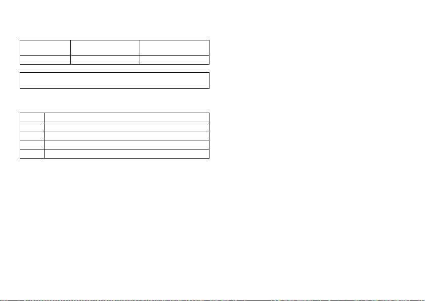
Varianty implantátu a kódy NBG
Skupina Evia
Jsou k dispozici následující varianty implantátu:
Typ implantátu Varianta s funkcí
3dutinový Evia HF-T Evia HF
Upozornění:
uveden v kapitole o nastavitelných parametrech.
Kód NBG pro Evia HF(-T)
DDDRV je kód NBG pro antibradykardický režim třídutinového implantátu:
D Stimulace v síni a v komoře
D Snímání v síni a v komoře
D Inhibice a spuštění impulzu
R Přizpůsobení frekvence
V Multisite stimulace v obou komorách
Home Monitoring
Nastavení režimu závisí na individuální diagnóze; přehled režimů je
Varianta bez funkce
Home Monitoring
Diagnostické a terapeutické funkce
Všeobecný přehled
Všechny systémy disponují množstvím funkcí k rychlému stanovení diagnózy
a bezpečné léčbě bradykardie.
•
Přes automatické funkce lze kardiostimulátor bez problémů a s časovou úsporou
implantovat, nastavit a zkontrolovat.
•
Automatická inicializace po implantaci: implantát automaticky rozpozná implantované elektrody, nastaví polaritu a aktivuje automatické funkce po 10 minutách.
Diagnostické funkce
•
Data posledních 10 interogací a follow-up stejně jako data arytmických epizod jsou
uložena společně s dalšími daty, aby mohla být kdykoliv využita pro posouzení pacientů i stavu implantátu.
•
Pro kontrolu funkčnosti elektrod je impedance v implantátu měřena nezávisle na
stimulačním impulzu - automaticky a podvědomě.
•
Při follow-up prostřednictvím programátoru je po přiložení programovací hlavice
během testu zobrazeno IEGM spolu s markery.
Antibradykardická stimulace
•
Snímání: amplitudy vlny P a R jsou v implantátu trvale, zcela automaticky měřeny,
aby byly zaznamenány i měnící se amplitudy. Citlivost pro síň a komoru je rovněž
plně automaticky, kontinuálně přizpůsobena. Data měření jsou zprůměrována a lze
zobrazit trend.
•
Stimulační prahy: jak síňové, tak komorové stimulační prahy jsou v implantátu
stanoveny automaticky, prostřednictvím řízení amplitud jsou nastaveny amplitudy
impulzů tak, že na každou změnu stimulačního prahu je pro pacienta nastavena
optimální síňová a komorová amplituda.
•
Časování: pro zabránění kardiostimulátorem vyvolané tachykardie je stimulace
v síni kontrolována automatickým přizpůsobením refrakterní periody. Automatická
PVARP (automatická postkomorová síňová refrakterní perioda).
•
Doplňková, zvláštní forma přizpůsobení frekvence: zvýšená potřeba minutového
objemu srdce je rozpoznána na základě fyziologického měření impedance. Princip
měření je založen na změněné kontraktilitě (ionotropii) myokardu (funkce CLS:
Closed Loop Stimulation). Vhodné přizpůsobení frekvence se automaticky inicializuje a optimalizuje v režimu CLS.
•
Potlačení komorové stimulace: nepotřebné komorové stimulaci je zabráněno
podporou vlastního převodu (funkce: Vp suppression). Implantát se přizpůsobí
změnám převodu. V případě vlastního vedení přístroj změní režim na DDD(R)ADI(R).
Resynchronizační léčba
Pro resynchronizaci komor mají třídutinové implantáty funkce pro "multisite" komorovou stimulaci s možným VV zpožděním v každém směru.
•
Funkce automatického řízení amplitud je dostupná i pro levou komoru a umožňuje
automatickou reakci na změnu stimulačního prahu nebo automatický monitoring
stimulačního prahu (ATM) za účelem analýzy jeho vývoje.
•
Pro zajištění toho, že nebude nutný žádný další chirurgický zákrok v případě levostranného zvýšení stimulačního prahu nebo nežádoucí stimulace frenického nervu,
mohou být pro levokomorovou elektrodu u třídutinového implantátu nastaveny
různé polarity stimulace.
•
Přídavná diagnostická funkce při biventrikulární stimulaci: variabilita srdeční frekvence, aktivita pacienta a impedance hrudníku jsou průběžně kontrolovány.
cs • Česky
25
Page 27

Programy
Existují dva druhy léčebných programů:
•
Pro nejčastější indikace nabízíme přednastavené parametry (funkce Program
Consult).
•
Individuální nastavení se dají uložit do tří individuálních léčebných programů.
Funkce Home Monitoring
Implantát automaticky odesílá jednou denně informace do pacientské jednotky. Doplňkově mohou být testovací zprávy inicializovány pomocí programátoru. Důležité lékařské
informace jsou mj. tyto:
•
trvalé síňové a komorové arytmie;
•
elektrodám relevantní parametry v síni a komoře: stimulační prahy, amplitudy
impedance, impedance;
•
aktuální statistiky léčby bradykardie;
•
individuálně nastavitelný časový interval pro zprávy implantátu, které poskytují
dodatečnou informaci týkající se zpráv z implantátu;
•
IEGM-Online HD® až se 3 kanály s vysokým rozlišením (High Definition);
•
vysílání těchto záznamů IEGM se zprávami implantátu.
Obsah balení
Standard
Ve skladovacím balení se nachází:
•
sterilní kontejner s implantátem,
•
štítek se sériovým číslem,
•
identifikační karta pacienta,
•
záruční list,
•
technická příručka pro implantát.
Ve sterilním kontejneru se nachází:
•
implantát,
•
šroubovák.
Objednací čísla Evia
Přístroje jsou dostupné takto:
Implantát Objednací číslo:
HF-T 381534 381535
HF 381532 381533
nepotažený
Objednací číslo:
potažený
2 Všeobecné bezpečnostní pokyny
Možné zdravotní komplikace
Všeobecné informace v případě zdravotních komplikací
Pro implantáty BIOTRONIK platí v odborné praxi všeobecně známé komplikace pro
pacienty a implantátové systémy.
•
Komplikace jsou např. nahromadění kapalin v kapse pro implantát, infekce nebo
reakce tkáně. Určující orientací je stav vědy a techniky.
•
Není možné zaručit účinnost léčby arytmie, i když bylo prokázáno, že jsou tyto léčby
úspěšné během testů nebo po elektrofyziologických vyšetřeních. V ojedinělých
případech mohou být nastavené parametry neúčinné. Je možné, že léčba indukuje
tachyarytmii.
Potenciály kosterních svalů
Bipolární snímání a kontrola citlivosti jsou implantátem přizpůsobeny frekvenčnímu
rozsahu vlastních rytmů tak, aby kostní myopotenciály nebyly obvykle detekovány.
Přesto mohou být – zvláště při unipolární konfiguraci a/nebo při velmi vysoké citlivosti –
klasifikovány kostní myopotenciály jako vlastní rytmy a – podle interference – mohou
způsobit inhibici nebo léčbu arytmie.
Stimulace nervů a svalstva
Použití implantátového systému sestávajícího z unipolární elektrody a nepotaženého
implantátu může při počátečním nebo trvale vysokém nastavení amplitudy impulz u vést
k nežádoucí stimulaci bránice.
•
BIOTRONIK nabízí také potažené implantáty.
26
Page 28

Možné technické komplikace
Technické závady
Technické závady systému implantátu v důsledku selhání součástky nemohou být
v podstatě vyloučeny. Mezi příčiny takových poruch patří:
•
posunutí elektrody,
•
zlomení elektrody,
•
defekty izolace,
•
vady komponentů implantátu,
•
vybití baterie.
Možné elektromagnetické komplikace
Elektromagnetická interference EMI
Každý implantát může být rušen, např. když jsou vnější signály vnímány jako vlastní
rytmus nebo když měření brání frekvenčnímu přizpůsobení.
•
Implantáty BIOTRONIK jsou konstruovány tak, že je jejich ovlivnitelnost elektromagnetickou interferencí (EMI) minimalizována.
•
Kvůli velké rozmanitosti a velkému počtu intenzit u EMI není možné zaručit absolutní bezpečnost. Obecně se vychází z toho, že EMI způsobuje, pokud vůbec, pouze
nepatrné symptomy u pacienta.
•
Podle druhu stimulace a interference mohou vést tyto zdroje k inhibici impulzu,
spuštění impulzu, ke zvyšování stimulační frekvence závislé od senzoru nebo asynchronní stimulaci.
•
Za nepříznivých podmínek, zejména v rámci diagnostických a terapeutických
procedur, mohou zdroje rušení navázat tak vysoké energie, že může dojít
k poškození tkáně obklopující implantát nebo hrot elektrody.
Postup s implantátem při EMI
Při elektromagnetických interferencích nebo nežádoucích myopotenciálech svalů se
implantát přepne po dobu překročení interferenční frekvence na asynchronní stimulaci.
Statická magnetická pole
Jazýčkový kontakt v kardiostimulátoru se uzavírá od intenzity pole 1,5 mT.
cs • Česky
Možná rizika
Kontraindikující postupy
V důsledku možného poškození pacienta nebo implantátu a z toho vyplývající funkční
nespolehlivosti je použití následujících postupů kontraindikováno:
•
terapeutický ultrazvuk; poškození pacienta nadměrným zahřátím tělesné tkáně
v oblasti implantátového systému;
•
transkutánní elektrická neuronální stimulace (TENS);
•
hyperbarická oxygenoterapie;
•
zatížení tlakem převyšujícím běžný tlak.
Rizikové terapeutické a diagnostické postupy
Pokud má pro diagnostické nebo terapeutické účely tělem procházet elektrický proud
z externího zdroje, může být implantát rušen a pacient ohrožen.
Při diatermických metodách jako je např. elektrokauterizace, HF-ablace nebo HFchirurgie je možná indukce arytmií nebo komorová fibrilace. Například u litotripse
může dojít ke škodlivému působení tepla. Působení na implantát nelze v některých
případech stanovit ihned.
Pokud není možné rizikové metody vyloučit, pak vždy platí:
•
Pacienta elektricky izolujte.
•
Funkci kardiostimulátoru případně přepněte na asynchronní režimy.
•
Zabraňte působení energií v blízkosti implantátového systému.
•
Dále zkontrolujte periferní pulz pacienta.
•
Při zákroku a po každém zákroku pacienta monitorujte.
Externí defibrilace
Implantát je chráněný proti energii, která je běžně indukovaná při externí defibrilaci.
Nicméně jakýkoli implantovaný přístroj může být při externí defibrilaci poškozen. Proud
indukovaný v implantovaných elektrodách může specificky vyvolat tvorbu nekrotické
tkáně v těsné blízkosti rozhraní elektrody a tkáně. Důsledkem toho se mohou změnit
vlastnosti snímání a stimulační prahy.
•
Nalepovací elektrody umístěte vpředu-vzadu nebo kolmo k ose vytvořené implantátem a srdcem, minimálně 10 cm od implantátu a od implantovaných elektrod.
Radiační léčba
V důsledku možného poškození implantátu a následné poruchy funkční bezpečnosti je
kontraindikována terapeutická radiační léčba. Pokud by měla být tato terapie přesto
použita, je bezpodmínečně nutné předchozí zvážení rizika. Komplexnost působících
27
Page 29

faktorů – například rozdílné zdroje záření, množství různých implantátů, podmínky
terapie – nedovoluje schválit směrnice, které by zaručovaly radiační léčbu bez působení
na implantát. Norma EN 45502 o aktivních implantovatelných medicínských přístrojích
vyžaduje v souvislosti s terapeutickým léčebným ionizujícím zářením tato opatření:
•
Respektujte upozornění týkající se rizikových terapeutických a diagnostických
postupů.
•
Zajistěte dostatečné stínění implantátu proti paprskům.
•
Po aplikaci záření zkontrolujte, zda implantátový systém pracuje správně.
Upozornění :
V případě dotazů týkajících se zvážení rizika kontaktujte firmu
BIOTRONIK.
Magnetická rezonance
Magnetická rezonance je kvůli s ní spojeným vysokofrekvenčním polím a hustotě
magnetického toku kontraindikující: poškození nebo zničení implantačního systému
v důsledku silných magnetických střídavých účinků a poškození pacienta nadměrným
zahřátím tělesné tkáně v oblasti implantátového systému.
Za určitých podmínek můžete provést při splnění předepsaných opatření k ochraně
pacientů a systému implantátu magnetickou rezonanční tomografii.
•
Příručka pro implantátové systémy pro podmíněné použití v MR - ProMRI® obsahuje podrobné informace o bezpečném vyšetření MRT.
—
Digitální příručku lze stáhnout z webové stránky:
www.biotronik.com/manuals/manualselection.
—
Tištěnou příručku lze objednat u firmy BIOTRONIK.
•
Platí povolení jako podmíněně použitelné pro MR ve Vaší zemi nebo ve Vašem
regionu? Aktuální informace si vyžádejte u firmy BIOTRONIK.
3 Před implantací
Indikace a kontraindikace
Směrnice kardiologických společností
Pro implantáty BIOTRONIK platí všeobecně známé metody rozdílové diagnostiky, indikace i doporučení pro kardiostimulátory.
Určující orientaci nabízejí pokyny kardiologických svazů.
Indikace
Doporučujeme sledovat indikace publikované německou kardiologickou společností
(Deutsche Gesellschaft für Kardiologie, Herz- und Kreislaufforschung) a ESC (European Society of Cardiology). Rovněž směrnice vydané Heart Rhythm Society (HRS), the
American College of Cardiology (ACC), the American Heart Association (AHA) a dále
směrnice dalších národních kardiologických asociací.
Kontraindikace
Nejsou známy žádné kontraindikace pro implantace multifunkčních třídutinových
implantací, za předpokladu, že implantaci předchází rozdílová diagnostika podle pokynů
a nejsou nastaveny režimy či kombinace parametrů ohrožující pacienta.
Upozornění :
Kompatibilita a účinnost kombinace parametrů musí být kontrolována
podle programování.
Okolní podmínky
Teplota
Jak extrémně nízké, tak vysoké teploty ovlivňují provozní dobu baterie v implantátu.
•
Povolené teploty pro přepravu, skladování a provoz jsou:
–10ºC až 45ºC.
Sklad
•
Implantáty nesmí být skladovány v blízkosti magnetů nebo zdrojů elektromagnetického rušení.
Doba skladování
Doba skladování ovlivňuje provozní dobu baterie implantátu, viz data o baterii.
•
Věnujte pozornost datu exspirace.
Sterilita
Dodávka
Implantát a příslušenství byly sterilizovány plynem. Sterilita je zaručena pouze v případě, že nedošlo k poškození plastového kontejneru a kontrolního těsnění.
28
Page 30

Sterilní kontejner
Implantát a příslušenství jsou baleny samostatně ve dvou oddělených zapečetěných
plastových kontejnerech. Vnitřní plastový kontejner je na vnější straně také sterilní, aby
mohl být přenesený jako sterilní během implantace.
Na jedno použití
Implantát a šroubovák jsou pouze na jedno použití.
•
Nepoužívejte, je-li balení poškozené.
•
Neprovádějte resterilizaci.
•
Nepoužívejte opakovaně.
Příprava implantace
Mějte připraven externí defibrilátor
V případě nepředvídaného kritického stavu nebo při případné technické závadě implantátu:
•
Mějte připraven externí defibrilátor.
Příprava součástí
Podle směrnice ES 90/385/EEC jsou potřebné tyto součásti:
•
implantát se šroubovákem firmy BIOTRONIK;
•
elektrody BIOTRONIK a souprava pro zavedení elektrody:
—
po jedné uni- nebo bipolární elektrodě pro síň a pravou komoru,
—
jedna uni- nebo bipolární elektroda pro levou komoru (koronární sinusová elektroda);
•
pro elektrody s jinými přípojkami nebo elektrody jiných výrobců používejte pouze
adaptéry schválené firmou BIOTRONIK;
•
programátor BIOTRONIK se schválenými kabely;
•
externí vícekanálový přístroj na EKG;
•
mějte vždy připravené rezervní součásti pro sterilní komponenty.
Vybalení implantátu
W
VAROVÁNÍ
Neadekvátní léčba kvůli poškozenému implantátu
Dojde-li při manipulaci s vybaleným implantátem k jeho pádu na tvrdý povrch, mohou
být elektronické díly poškozeny.
•
Použijte náhradní implantát.
•
Poškozený implantát odešlete do firmy BIOTRONIK.
cs • Česky
•
Odlepte těsnicí papír v nějšího plastového kontejneru na označeném míst ě ve směru
vyznačeném šipkou. Vnitřní plastový kontejner nesmí přijít do kontaktu s osobami,
které nemají sterilní ruce nebo rukavice ani s nesterilními předměty!
•
Uchopte vnitřní plastový kontejner pomocí poutka pro uchycení a vyjměte jej z vnějšího plastového kontejneru.
•
Odlepte těsnicí papír sterilního vnitřního plastového kontejneru na označeném
místě ve směru vyznačeném šipkou.
Upozornění:
Implantát je během dodávky deaktivován a lze jej po vybalení bez manu-
ální aktivace ihned implantovat.
4 Implantace
Implantace
Místo implantace
Kardiostimulátor se zpravidla implantuje subkutánně nebo pod pektorální sval na pravé
straně v závislosti na konfiguraci elektrody a rovněž na anatomické dispozici pacienta.
Průběh
1 Vytvarujte kapsu pro implantát a připravte žílu.
2 Implantujte elektrody a proveďte měření.
3 Připojte implantát a elektrody.
Implantát spustí samostatně automatickou inicializaci.
4 Vložte implantát.
5 Provlékněte fixační nit skrz otvor v rozdělovači a implantát zafixujte
v připravené kapse.
6 Uzavřete kapsu implantátu.
7 Před testem a nastavením vyčkejte úspěšného ukončení automatické
inicializace implantátu.
Upozornění:
V případě potřeby lze implantát programovat i před nebo během auto-
matické inicializace.
29
Page 31

Položení programovací hlavice
Na programovací hlavici (PGH) se nachází schematický nákres implantátu. Tento
nákres slouží jako polohovací pomůcka při přiložení pro zajištění správné telemetrie.
•
Dbejte správného umístění PGH.
Připojení elektrod kardiostimulátoru
Možnosti připojení
Kardiostimulátory od BIOTRONIK jsou konstruovány pro elektrody s uni- nebo bipolární
přípojkou IS-1. Pro snímání a stimulaci lze připojit jednu unipolární nebo jednu bipolární elektrodu:
•
síň: IS-1 unipolární nebo bipolární;
•
pravá a levá komora: IS-1 unipolární nebo bipolární.
Upozornění :
Používejte pouze adaptéry schválené firmou BIOTRONIK pro elektrody
s různými přípojkami.
•
Budete-li mít otázky týkající se kompatibility s elektrodami jiných výrobců,
kontaktujte firmu BIOTRONIK.
Diagram propojení
Diagram připojení pro třídutinové implantáty:
DDDRV
LV
A
RV
IS-1
Zabránění zkratu v rozdělovači
W
VAROVÁNÍ
Zkrat v důsledku otevřených připojení elektrod
Otevřené a tím pro elektrolyt netěsná spojení v rozdělovači mohou vyvolat nežádoucí
toky proudů do těla a průnik tělesné tekutiny do implantátu.
•
Nepoužité přípojky uzavřete zaslepujícími zástrčkami.
Připojení konektoru elektrody k implantátu
1 Odpojte stylety a zaváděcí pomůcky od konektoru elektrody.
2•Připojte uni- nebo bipolární konektor IS-1 komory k RV.
•
Připojte uni- nebo bipolární konektor IS-1 předsíně k A.
•
Připojte uni- nebo bipolární konektor IS-1 komory k LV.
3 Zasuňte konektor elektrody do rozdělovače bez ohnutí přívodu tak, až bude vidět
hrot konektoru za blokem šroubů.
4 Pokud není možné úplně zavést konektor elektrody, je to eventuálně způsobeno
tím, že upevňovací šroub zasahuje do otvoru bloku šroubů. Opatrně povolte
upevňovací šroub, aniž byste jej úplně vyšroubovali, aby se při zašroubování
nezpříčil.
5 Propíchněte silikonovou zástrčku uprostřed na rozří znutém místě svisle pomocí
šroubováku až po upevňovací šroub.
6 Otáčejte upevňovací šroub ve směru hodinových ručiček, dokud nedosáhnete
kontroly krouticího momentu (slyšitelné cvaknutí).
7 Opatrně vytáhněte šroubovák, upevňovací šroub se přitom nesmí otáčet zpět.
•
Když vytahujete šroubovák, utěsní silikonová zástrčka automaticky
a bezpečně připojení elektrody.
Dodržení odstupu mezi elektrodami
W
VAROVÁNÍ
Neadekvátní terapie
Pokud nemají elektrody dostatečný vzájemný odstup nebo jsou nevhodně umístěny,
může dojít ke snímání vzdálené oblasti nebo k nedostatečné defibrilaci.
•
Hrotové a prstencové elektrody se nesmí vzájemně dotýkat.
Automatická inicializace
Když je první připojená elektroda detekována, začíná samočinně automatická inicializace.
Deset minut po připojení první elektrody je automatická inicializace ukončena. V případě, že mezitím není přenášen žádný další program, pracuje implantát následně s aktivními automatickými funkcemi ve standardním programu.
30
Page 32

Manuální nastavení polarity elektrody nebo měření impedance elektrod není požadováno.
Upozornění:
Po automatické inicializaci jsou všechny parametry aktivovány ve stan-
dardním programu až na tyto výjimky:
•
DDD,
•
automaticky zjištěná konfigurace elektrody (unipolární nebo bipolární) je
nastavena.
Reakce během automatické inicializace
•
Při přeprogramování:
automatická inicializace je přerušena, přenášený program je ihned aktivní.
•
Při provedení testu:
automatická inicializace následně pokračuje.
•
Při přenosu permanentního programu:
automatická inicializace je ukončena a přenášený program je aktivní.
Bezpečnostní opatření při programování
Kontrola implantátového systému
•
Po automatické inicializaci proveďte follow-up, abyste zjistili přiměřenou funkčnost
implantátového systému.
•
Pro stanovení stimulačního prahu proveďte test stimulačního prahu.
Provádění standardních testů a monitorování pacienta
Ke kritickému stavu pacienta může dojít i v průběhu standardních testů například kvůli
nastavení neadekvátních parametrů nebo kvůli přerušené telemetrii.
•
Proto dbejte také při testech na dostatečnou péči o pacienta.
•
Po testu stimulačního prahu zkontrolujte, zda je tento práh oprávněný z klinického
a technického hlediska.
•
EKG a stav pacientů kontinuálně monitorujte.
•
V případě potřeby test přerušte.
Přerušení telemetrie
Porucha programátorů nebo telemetrická interference, ke které dojde během provádění dočasných programů (sledovací testy), může způsobit neadekvátní stimulaci pacienta. To je případ, kdy nelze programátor kvůli chybě programu nebo defektu dotykové
obrazovky dále obsluhovat a následkem toho není možné dočasný program ukončit.
V takovém případě pomůže přerušení telemetrie, přičemž implantát automaticky
přechází do permanentního programu.
•
Při telemetrii s PGH - nadzvedněte programovací hlavici o minimálně 30 cm.
•
Vypněte možné zdroje poruchy.
Vyhněte se kritickému nastavení parametrů
Nesmí se nastavovat režimy a kombinace parametrů ohrožující pacienta.
•
Před nastavením přizpůsobení frekvence stanovte mez zatížení pacienta.
•
Po nastavení zkontrolujte snášenlivost a účinnost kombinace parametrů.
Manuální nastavení polarity elektrody
Kvůli nebezpečí bloku vstupu/výstupu smí být bipolární polarita elektrody (snímání/
stimulace) nastavena pouze poté, když jsou implantovány rovněž bipolární elektrody.
Rozpoznání defektů elektrody
Automatické měření impedance je neustále zapnuto.
•
Hodnoty impedance, které poukazují na technické závady elektrod, jsou dokumentovány v seznamu událostí.
Nastavení režimu spuštěné stimulace
Režimy spuštěné stimulace stimulují nezávisle na vlastním rytmu. Abyste zabránili ve
zvláštních případech nedostatečnému snímání kvůli elektromagnetické interferenci,
lze zobrazit režim spuštěné stimulace.
Nastavení snímání
Manuálně nastavené parametry mohou být nespolehlivé, například nevhodná ochrana
vzdáleného pole (far-field) může zabránit snímání intrinsických impulzů.
•
Používejte automatickou regulaci citlivosti.
Nastavení citlivosti
Když je pro citlivost implantátu nastavena hodnota < 2,5 mV/unipolárně, může dojít
k rušení elektromagnetickými poli.
•
Podle odstavce 28.22.1 normy EN 45502-2-1 se proto doporučuje nastavit hodnotu
≥ 2,5 mV/unipolární. Nastavení hodnot citlivosti < 2,5 mV/unipolární vyžaduje explicitní klinickou nutnost. Takové hodnoty lze nastavovat nebo kontrolovat pouze pod
lékařským dohledem.
cs • Česky
31
Page 33

Zabránění komplikacím indukovaných implantátem
Implantáty firmy BIOTRONIK obsahují několik funkcí, pomocí kterých je možné pokud
možno spolehlivě zabránit komplikacím indukovaným implantátem.
•
Změřte retrográdní dobu převodu.
•
Pokud funkce již není správně automaticky nastavena: zapněte ochranu PMT.
•
Nastavte kritérium VA.
Informace pro chování magnetu
Při vložení magnetu nebo programovací hlavice může dojít k fyziologické změně rytmu
a k asynchronní stimulaci. Chování magnetu je u kardiostimulátoru BIOTRONIK nastaveno jako u standardního programu:
•
asynchronní:
pro dobu režimu D00 vložení magnetu (příp. V00/A00) bez přizpůsobení frekvence,
magnetická frekvence: 90 bpm;
•
automaticky:
pro 10 cyklů režimu D00, potom režim DDD bez přizpůsobení frekvence,
magnetická frekvence: 10 cyklů s 90 bpm, potom nastavená základní frekvence;
•
synchronní:
režim DDD bez přizpůsobení frekvence,
magnetická frekvence: nastavená základní frekvence.
Upozornění :
K chování magnetu při ERI viz informace ohledně indikací pro výměnu.
Zabránění převodu síňové tachykardie
Implantáty firmy BIOTRONIK obsahují několik funkcí pro zabránění převodu síňové
tachykardie do komory:
•
Pro indikované pacienty nastavte režim Mode Switch.
•
Nastavte horní hraniční frekvenci a refrakterní periodu tak, aby se zamezilo náhlým
změnám komorové frekvence.
•
Preferujte Wenckebachův fenomén a vyhýbejte se chování 2:1.
•
Nastavte všechny parametry tak, aby nedocházelo k neustálému střídání mezi síňově a komorově řízenými režimy.
Nežádoucí nepřetržitá stimulace frenického nervu
V nemnohých případech není možné při stimulaci levé komory zabránit chronické
stimulaci frenického nervu přeprogramováním stávající stimulační konfigurace levé
komory nebo pomocí jiných opatření.
•
Případně nastavte pravokomorový režim jak v permanentním programu, tak také
v režimu Mode Switch.
Zabránění rizik u stimulace výhradně levé komory
Pokud dojde u stimulace výhradně levé komory k posunutí elektrody, hrozí následující
rizika: ztráta komorové stimulace a rovněž indukce síňových arytmií.
•
Zvažte parametry snímání a stimulace z hlediska ztráty léčby.
•
U pacientů, kteří jsou závislí na implantátu se stimulace výhradně levé komory
nedoporučuje.
•
Zohledněte riziko možného přerušení automatického řízení amplitud.
•
Při follow-up a při testech stimulačního prahu zohledněte ztrátu synchronizované
ventrikulární stimulace.
Při současně implantovaném ICD není povolena unipolární stimulace
Pokud je s kardiostimulátorem současně implantován ICD a vyskytne-li se defekt elektrod, lze po obnovení původního nastavení kardiostimulátoru nebo pomocí automatické
zkoušky elektrod přepnout na unipolární stimulaci. Tím může ICD mylně inhi bovat nebo
aktivovat léčbu tachyarytmie.
•
V této konfiguraci nejsou unipolární elektrody povoleny.
Zohlednění spotřeby proudu a provozní doby
Kardiostimulátor povoluje programování vysokých amplitud impulzu s dlouhou šířkou
impulzu při vysokých frekvencích, aby mohla adekvátně probíhat léčba i při nezvyklých
diagnózách. V kombinaci s nízkou impedancí elektrod to vede k velmi vysoké spotřebě
proudu.
•
Při programování velkých hodnot parametrů zohledněte, že indikátor výměny ERI
bude dosažen velmi brzo, protože provozní doba baterie může klesnout na méně
než 1 rok.
5 Po implantaci
Follow-up
Intervaly mezi kontrolami
Follow-up musí probíhat v pravidelných, sjednaných intervalech.
•
Po skončení fáze zarůstání elektrod, přibližně 3 měsíce po implantaci, musí být
provedena první follow-up u lékaře s programátorem (prezenční follow-up).
32
Page 34

•
Jednou ročně, nejpozději 12 měsíců po poslední prezenční follow-up, musí být
provedena další prezenční follow-up.
Follow-up pomocí BIOTRONIK Home Monitoring®
Kontrola pomocí Home Monitoring nenahrazuje pravidelnou osobní návštěvu u lékaře,
která je nutná z jiných lékařských důvodů.
Follow-up zprostředkovaná funkcí Home Monitoring může prezenční follow-up
nahradit za těchto předpokladů:
•
Pacient byl informován, že přes kontrolu pomocí Home Monitoring (domácí monitoring) je nutné kontaktovat lékaře, pokud symptomy zesílí nebo se vyskytnou nové.
•
Zprávy implantátu jsou zasílány v pravidelných intervalech.
•
Lékař rozhodne, zda jsou data získaná od Home Monitoring s ohledem na klinický
stav pacienta a technický stav systému implantátu dostačující; pokud ne, musí být
provedena prezenční follow-up.
Možná časná detekce z informací získaných pomocí Home Monitoring může vyvolat
nutnost dodatečné prezenční kontroly. Např. mohou dodaná data předčasně upozorňo-
vat na problémy s elektrodami nebo na dohledný konec servisní doby (ERI). Dále mohou
data upozorňovat na detekci doposud nerozpoznaných arytmií nebo na změnu léčby
pomocí přeprogramování implantátu.
Follow-up pomocí programátoru
Při prezenční kontrole postupujte takto:
1 Záznam a vyhodnocení externího EKG
2 Kontrola funkce snímání a stimulační funkce
3 Interogace implantátu
4 Vyhodnocení stavu a automaticky naměřených follow-up dat
5 Případné vyhodnocení statistik a záznamů IEGM
6 V případě potřeby manuální provedení standardních testů
7 Případné přizpůsobení funkcí programu a parametrů
8 Permanentní přenos programu na implantát
9 Tisk (tiskový protokol) a dokumentace follow-up dat
10 Ukončení follow-up příslušného pacienta
Poznámky pro lékaře
Identifikační karta pacienta
Obsahem dodávky je identifikační karta pacienta.
•
Identifikační kartu pacienta předejte pacientovi.
•
Poučte pacienta o tom, aby se v případě nejasností obrátil na lékaře.
Značka zákazu
Místům se značkami zákazu je nutné se vyhýbat.
•
Upozorněte pacienta na značku zákazu.
Možné zdroje poruchy
V každodenním životě by se pacient měl vyhýbat elektromagnetickým interferencím;
v blízkosti implantátu by se neměly nacházet zdroje rušení.
•
Upozorněte pacienta také na zvláštní domácí spotřebiče, bezpečnostní propusti/
zařízení zajištění proti krádeži, silná elektromagnetická pole, mobilní telefony
a vysílače.
•
Vyzvěte pacienta k následujícím opatřením:
—
používání mobilního telefonu na opačné straně, než se nachází implantát;
—
pacient by měl mobilní telefon držet minimálně 15 cm od implantátu, a to jak
při jeho používání, tak také při uschování.
Přiložení magnetu prostřednictvím pacientů
Má-li být pacientům dána možnost přiložení magnetu, musí být naprogramován na
synchronní magnetický efekt. Pacienti musejí vědět následující:
•
Kdy smí být magnet použit?
Při silné závrati a nevolnosti.
•
Jak dlouho má být magnet přiložen ke kardiostimulátoru?
1 až 2 s.
•
Co se děje při přiložení magnetu:
IEGM posledních 10 předchozích sekund uloží do paměti.
•
Co musí být provedeno po přiložení magnetu?
Navázání kontaktu pacienta s lékařem za účelem follow-up.
cs • Česky
33
Page 35

Indikace pro výměnu
Provozní stavy kardiostimulátoru
Časové rozpětí mezi začátkem provozu BOS po dosažení indikace pro výměnu ERI je
určeno mj. následovně:
•
kapacita baterie,
•
impedance elektrod,
•
stimulační program,
•
poměr mezi stimulací a inhibicí,
•
funkční vlastnosti obvodu kardiostimulátoru.
Definované provozní stavy kardiostimulátoru jsou tyto:
BOS
Začátek servisu (Beginning of
Service)
ERI
Zvolená indikace výměny (Elective
Replacement Indication)
EOS
Konec servisu (End of Service) Konec serv isní doby s obvyklou činnos-
Aktivace ERI
Detekce ERI je aktivována automaticky podle těchto událostí:
•
úspěšná automatická inicializace,
•
doba skladování déle než 24 měsíců.
Zobrazení ERI
ERI je zobrazováno takto:
•
na programátoru po interogaci kardiostimulátoru;
•
přes definovaný pokles jak naprogramované základní, tak i magnetické frekvence.
Změna režimu při ERI
Z třídutinových režimů přejde kardiostimulátor do dvoudutinové stimulace; tato změna
závisí na naprogramovaném režimu a je zobrazena na programátoru.
Deaktivované funkce při ERI
Deaktivovány jsou tyto funkce:
•
síňová stimulace,
•
noční program,
Baterie je v dobrém stavu; běžná
follow-up.
Bod výměny byl dosažen. Kardiostimulátor se musí vyměnit.
tí kardiostimulátoru.
•
přizpůsobení frekvence,
•
síňové a komorové řízení amplitud,
•
Rate Fading (vyhlazení frekvence),
•
síňová overdrive stimulace,
•
záznamy IEGM,
•
statistiky,
•
Home Monitoring,
•
frekvenční hystereze,
•
potlačení komorové stimulace.
Pokles frekvence
Pokles základní frekvence a magnetické frekvence je definován takto:
•
Stimulační frekvence se snižuje o 11 % v těchto režimech:
DDD(R); DDT(R); DOO(R); VDD(R); VDI(R); VVI(R); VVT(R); AAI(R); AAT(R); AOO(R).
•
V režimech DDI(R) a DVI(R) se pouze prodlužuje doba VA o 11 %. Tím se sníží stimulační frekvence vždy podle nastavené doby AV o 4,5 až 11 %.
Chování magnetu při ERI
Po dosažení ERI je podle přiložení magnetu nebo programovací hlavice stimulace
následující:
Magnetický
efekt
Automatický Asynchronní s 80 bpm Synchronní s o 4,5 až 11 %
Asynchronní Asynchronní s 80 bpm Asynchronní s 80 bpm
Synchronní Synchronní s o 4,5 až 11 %
Očekávaná servisní doba po dosažení ERI
•
Data jsou založena na impedanci elektrod 500 Ω, 100 % stimulaci a datech od
výrobce baterie
•
Parametry při vysoké stimulační energii:
110 bpm; 4,6 V; 1,5 ms; 500 Ω
•
Parametry při nízké stimulační energii:
30 bpm; 0,2 V; 0,1 ms; 500 Ω
Cykly 1 až 10: Po 10 cyklech:
zredukovanou základní frekvencí
zredukovanou základní frekvencí
Synchronní s o 4,5 až 11 %
zredukovanou základní frekvencí
34
Page 36

•
Interval od ERI do EOS u třídutinového implantátu v režimu DDD(R), ve standardním
programu a jak při vysoké, tak při nízké stimulační energii:
—
střední hodnota: 8 měsíců;
—
minimální hodnota: 6 měsíců.
Explantace a výměna implantátu
Explantace
•
Odpojte elektrody od rozdělovače.
•
Vyjměte implantát a - v případě potřeby - i elektrody pomocí zavedené technologie.
•
Explantáty jsou biologicky kontaminované a musejí být kvůli riziku infekce bezpečně
zlikvidovány.
Výměna implantátu
Pro elektrody předchozího implantátu, které zůstanou v používání, platí:
•
Před připojením k novému implantátu elektrody zkontrolujte.
Nejsou-li již implantované elektrody dále využívány, ale zůstanou ponechány v těle pacienta, může dojít ke vzniku dodatečné a nekontrolované cesty proudu k srdci.
•
Nepoužívaná připojení izolujte.
Zásadně platí:
•
Neprovádějte resterilizaci implantátu a nepoužívejte opakovaně.
Kremace
Implantát nesmí být spálen.
•
Před zpopelněním mrtvého pacienta musí být implantát explantován.
Odstranění
BIOTRONIK odebírá použité výrobky zpět pro odstranění způsobem, který neohrožuje
životní prostředí.
•
Explantát vyčistěte nejméně jednoprocentním roztokem chlornanu sodného.
•
Opláchněte ho vodou.
•
Vyplňte formulář explantace a spolu s čistým explantátem jej odešlete do firmy
BIOTRONIK.
6 Parametr
Režimy
Skupina Evia
Nastavení režimu závisí na individuální diagnóze:
Typ implantátu Režim Standard
HF(-T)
Upozornění:
Časování - 3dutinový
Základní frekvence den/noc
Parametry Rozpětí hodnot Standard
Základní frekvence 30 ... (1) ... 88 ... (2) ... 122 ... (3) ... 140
Noční frekvence OFF
Začátek noci 00:00 ... (10 min) ... 23:50 hh:mm 22:00 hh:mm
Konec noci 00:00 ... (10 min) ... 23:50 hh:mm 06:00 hh:mm
•
DDD-CLS; VVI-CLS
•
DDDR; DDIR; DVIR; DOOR
VDDR; VDIR; VVIR; VVTR; VOOR
AAIR; AATR; AOOR
•
DDD; DDT; DDI; DVI; DOO
VDD; VDI; VVI; VVT; VOO
AAI; AAT; AOO
•
DDD-ADI; DDDR-ADIR
•
OFF
Home Monitoring (domácí monitoring) je možný ve všech režimech.
... (5) ... 200 bpm
30 ... (1) ... 88 ... (2) ... 122 ... (3) ... 140
... (5) ... 200 bpm
DDDR
60 bpm
OFF
cs • Česky
35
Page 37

Frekvenční hystereze
Parametry Rozpětí hodnot Standard
Frekvenční hystereze OFF
Repetitivní hystereze OFF; 1 ... (1) ... 15 5
Vyhledávací hystereze OFF; 1 ... (1) ... 15 5
AV zpoždění, VV zpoždění
Parametry Rozpětí hodnot Standard
AV zpoždění Nízké; střední; vysoké; fixní; individuální Nízké
Kompenzace snímání OFF
AV bezpečnostní interval 100 ms 100 ms
VV zpoždění po Vp 0...(5)...80; 90; 100 ms 0
AV hystereze
Parametry Rozpětí hodnot Standard
Hystereze AV OFF
Všechny režimy kromě
negativních:
AV repetitivní hystereze/
vyhledavaci hystereze
Negativní režimy:
AV repetitivní hystereze/
vyhledavaci hystereze
-5 ... (-5) ... -90 bpm
15 ... (5) ... 350 ms
(v 6 frekvenčních rozsazích)
-10 ... (5) ... -120 ms
Negativní, nízká; střední; vysoká;
IRSplus
OFF
1 ... (1) ... 10
OFF
1 ... (1) ... 10 ... (5) ... 100 ... (10) ... 180
OFF
150 až 120 ms
-45 ms
OFF
OFF
OFF
Potlačení komorové stimulace
Parametry Rozpětí hodnot Standard
Potlačení komorové stimulace OFF; ON OFF
Potlačení stimulace po konsekutivní Vs 1 ... (1) ... 8 6
Stimulace podporována po X z 8 cyklů 1; 2; 3; 4 3
Horní hraniční frekvence
Parametry Rozpětí hodnot Standard
Horní hraniční frekvence 90 ... (10) ... 200 bpm 130 bpm
Horní hraniční frekvence, síň OFF
Mode Switching
Parametry Rozpětí hodnot Standard
Mode Switching OFF; ON ON
Intervenční frekvence 100 ... (10) ... 250 bpm 160 bpm
Přepnutí na (režim) DDI; DDI(R), při trvalém DDD(R)
Kritérium aktivace 3 ... (1) ... 8 5
Kritérium deaktivace 3 ... (1) ... 8 5
Změna základní frekvence
při Mode Switching
Ustálení frekvence OFF; ON OFF
Refrakterní periody
Parametry Rozpětí hodnot Standard
Síňová refrakterní perioda AUTO AUTO
Síňová refrakterní perioda
v režimu AAI(R); AAT(R); DDT
240 bpm
VDI; VDI(R) při trvalém VDD(R)
OFF
+5 ... (5) ... +30 bpm
300 ... (25) ... 775 ms 350 ms
36
240 bpm
DDI(R)
VDI(R)
+10 bpm
Page 38

Parametry Rozpětí hodnot Standard
PVARP AUTO
PVARP po PVC PVARP + 150 ms (max: 600 ms)
Komorová refrakterní perioda 200 ... (25) ... 500 ms 250 ms
Doby zaslepení
Parametry Rozpětí hodnot Standard
Ochrana vzdáleného pole po Vs 100 ... (10) ... 220 ms 100 ms
Ochrana vzdáleného pole po Vp 100 ... (10) ... 220 ms 150 ms
Komorové nulování po Ap 30 ... (5) ... 70 ms 30 ms
Ochrana PMT
Parametry Rozpětí hodnot Standard
Detekce/ukončení PMT OFF; ON ON
Kritérium VA 250 ... (10) ... 500 ms 350 ms
175 ... (5) ... 600 ms
je automaticky naprogramované
AUTO
400 ms
Stimulace a snímání - 3dutinový
Amplituda impulzu a šířka impulzu
Parametry Rozpětí hodnot Standard
Amplituda impulzu A 0,2 ... (0,1) ... 6,0 ... (0,5) ... 7,5 V 3,0 V
Šířka impulzu A 0,1 ... (0,1) ... 0,5; 0,75; 1,0; 1,25; 1,5 ms 0,4 ms
Amplituda impulzu RV/LV 0,2 ... (0,1) ... 6,0 ... (0,5) ... 7,5 V 3,0 V
Šířka impulzu RV/LV 0,1 ... (0,1) 0,5; 0,75; 1,0; 1,25; 1,5 ms 0,4 ms
Citlivost
Parametry Rozpětí hodnot Standard
Citlivost A AUTO
Citlivost RV AUTO
Citlivost LV OFF; AUTO
Síňové řízení amplitud
Parametry Rozpětí hodnot Standard
Síňové řízení amplitud ATM (jen monitoring)
Min. amplituda 0,5 ... (0,1) ... 4,8 V 1,0 V
Spuštění testu stimulačního prahu 2,4; 3,0; 3,6; 4,2; 4,8 V 3,0 V
Bezpečnostní rozpětí 0,5 ... (0,1) ... 1,2 V 1,0 V
Vyhledávací režim Interval; denní doba Denní doba
Interval 0,1; 0,3; 1; 3; 6; 12; 24 h 24 h
Denní doba 00:00 ... (10 min) ... 23:50 ... 02:00 hh:mm
Komorové řízení amplitud
Parametry Rozpětí hodnot Standard
Řízení amplitud RV/LV ATM (jen monitoring)
Min. amplituda 0,7 V 0,7 V
Spuštění testu stimulačního prahu 2,4; 3,0; 3,6; 4,2; 4,8 V 3,0 V
Bezpečnostní rozpětí RV 0,3 ... (0,1) ... 1,2 V 1,0 V
Bezpečnostní rozpětí LV 1,0; 1,2 V 1,0 V
Vyhledávací režim Interval; denní doba Denní doba
Interval 0,1; 0,3; 1; 3; 6; 12; 24 h 24 h
Denní doba 00:00 ... (10 min) ... 23:50 02:00 hh:mm
0,1 ... (0,1) ... 1,5 ... (0,5) ... 7,5 mV
0,5 ... (0,5) ... 7,5 mV
0,5 ... (0,5) ... 7,5 mV
ON; OFF
ON; OFF
AUTO
AUTO
AUTO
ON
ON
cs • Česky
37
Page 39

Síňová overdrive stimulace
Parametry Rozpětí hodnot Standard
Síňová overdrive stimulace
Konfigurace elektrod
Parametry Rozpětí hodnot Standard
Polarita snímání A a RV/LV Unipolární, bipolární Unipolární
Polarita stimulace A a RV Unipolární, bipolární Unipolární
Polarita stimulace LV LV hrot-> LV prstenec
Záznamy IEGM
Parametry Rozpětí hodnot Standard
Záznamy IEGM 20 (počet); každý max. 10 s
Typy záznamů IEGM Vysoká síňová frekvence (HAR) HAR
Záznam IEGM před událostí 0; 25; 50; 75; 100% 75%
Signál IEGM Filtrovaný, bez filtrování Filtrovaný
Frekvence pro statistiku
Parametry Rozpětí hodnot Standard
Vysoká síňová frekvence (HAR) 100 ... (5) ... 250 bpm
ON; OFF OFF
LV-hrot -> RV-prstenec
LV prstenec -> LV hrot
LV-prstenec -> RV-prstenec
LV-hrot -> pouzdro
LV-prstenec -> pouzdro
Mode Switching
Vysoká komorová frekvence (HVR) ON
Vyvolané pacientem (patient-triggered) OFF
600; 572 ... 245; 240 ms
LV-hrot –> pouzdro
200 bpm
300 ms
Parametry Rozpětí hodnot Standard
Vysoká komorová frekvence
(HVR)
Čítač HVR 4; 8; 12; 16 8
150 ... (5) ... 200 bpm
400; 387 ... 308; 300 ms
180 bpm
333 ms
Přizpůsobení frekvence
Přizpůsobení frekvence pomocí Closed Loop Stimulation (CLS)
Režimy CLS:
Parametry Rozpětí hodnot Standard
Maximální frekvence CLS 80 ... (5) ... 160 bpm 120 bpm
CLS-Dynamika Velmi nízký; nízký; střední; vysoký; velmi
Dynamický limit frekvence OFF; +10 ... (10) ... +50 bpm +20 bpm
Vp potřebné Ano, ne Ano
Přizpůsobení frekvence pomocí akcelerometru
Režimy R:
Parametry Rozpětí hodnot Standard
Senzor přírůstku 1 ... 23 4
Max. aktivační frekvence 80 ... (5) ... 180 bpm 120 bpm
Automatický přírůstek OFF; ON ON
Práh senzoru Velmi nízký; nízký; střední; vysoký;
Zvýšení frekvence 1 ... (1) ... 10 bpm/cyklus 4 bpm/cyklus
Snížení frekvence 0,1; 0,2; 0,5; 1,0 bpm/cyklus 0,5 bpm/cyklus
Rate Fading (vyhlazení
frekvence)
vysoký
velmi vysoký
OFF; ON OFF
Střední
38
Střední
Page 40

Předvolené programy - třídutinové
Standardní a bezpečnostní program
Pouze funkce Automatická inicializace je aktivována. Všechny ostatní funkce standardního programu jsou deaktivovány.
Parametry Standardní
Režim (podle automatické inicializace: DDD) DDDR VVI
Základní frekvence 60 bpm 70 bpm
Noční program OFF OFF
Frekvenční hystereze OFF OFF
Horní hraniční frekvence 130 bpm —
Dynamická doba zpoždění AV Nízká —
AV hystereze OFF —
Kompenzace snímání -45 ms —
AV-bezpečnostní interval 100 ms —
VV zpoždění — —
Ochrana T-vlny levé komory ON ON
Ochrana vzdáleného pole po Vs 100 ms —
Ochrana vzdáleného pole po Vp 150 ms —
Komorová doba nulování (po Ap) 30 ms —
Ochrana PMT ON —
Kritérium VA 350 ms —
Chování po přiložení magnetu AUTO AUTO
Amplituda impulzu A 3,0 V —
Amplituda impulzu RV, LV 3,0 V 4,8 V
Šířka impulzu A 0,4 ms —
Šířka impulzu RV, LV 0,4 ms 1,0 ms
Citlivost A AUTO —
Citlivost RV, LV AUTO 2,5 mV
Refrakterní perioda A AUTO —
cs • Česky
program
Ochranný
program
Parametry Standardní
Refrakterní perioda RV 250 ms 300 ms
Refrakterní perioda LV 200 ms 200 ms
Mode Switching ON —
Kriterium aktivace 5 z 8 —
Kritérium deaktivace 5 z 8 —
Intervenční frekvence 160 bpm —
Přepnutí na DDIR —
Základní frekvence při Mode Switching +10 bpm —
Stabilizace frekvence při Mode Switching OFF —
Ochrana proti 2:1 lock-in, ON —
PVARP AUTO —
PVARP po PVC (komorová extrasystola) 400 ms —
Konfigurace elektrody je stanovena automaticky a provede se nastavení:
Polarita stimulace A/RV/LV Unipolární Unipolární
Polarita snímání A/RV/LV Unipolární Unipolární
Automatická kontrola elektrod A/RV/LV ON —
Řízení amplitud A/RV/LV ON OFF
Síňová overdrive stimulace OFF —
Potlačení komorové stimulace OFF —
Záznam IEGM (HAF, HVF) ON OFF
Home Monitoring (domácí monitoring) OFF OFF
program
39
Ochranný
program
Page 41

Tolerance hodnot parametrů
Třídutinový
Parametr Rozpětí hodnot Tolerance
Základní frekvence 30 ... 100 bpm +/-1,5 bpm
Základní interval 1000 ms +/-20 ms
Magnetická frekvence 90 bpm +/-1,5 bpm
Magnetický interval 664 ms +/-20 ms
AV zpoždění 15 ... 350 ms +20/-5 ms
Amplituda impulzu A/RV/LV 0,2 V +/-0,10 V
Délka impulzu A/RV/LV 0,1 ... 0,4 ms +/-0,04 ms
Citlivost A
45502-2-1 trojúhelníkový impulz
Citlivost RV/LV
45502-2-1 trojúhelníkový impulz
Refrakterní perioda A 300 ... 775 ms +10/-30 ms
Refrakterní perioda RV/LV 200 ... 500 ms +10/-30 ms
PVARP 175 ... 600 ms +10/-30 ms
PVARP po PVC 325 ... 600 ms +10/-30 ms
Max. aktivační frekvence 80 ... 100 bpm +/-1,5 bpm
Horní hraniční frekvence 90 ... 190 bpm +/-2,0 bpm
High Rate Protection 200 bpm +20/-0 bpm
102 ... 195 bpm +/-2,0 bpm
200 bpm +0,0/-3,0 bpm
0,3 ... 7,5 V +20/-25%
0,5 ... 1,0 ms +/-0,10 ms
1,25 ... 1,5 ms +/-0,15 ms
0,1 mV +0,2/-0,1 mV
0,2 ... 0,5 mV +/-0,1 mV
0,6 ... 7,5 mV +/-20%
0,5 mV +/-50%
1,0 ... 7,5 mV +/-20%
105 ... 180 bpm +/-2,0 bpm
200 bpm +0/-2,0 bpm
Parametr Rozpětí hodnot Tolerance
Impedance elektrod 100 ... 200 Ω +/-50 Ω
201 ... 2 500 Ω +/-25%
7 Technické parametry
Mechanické parametry
Rozměrové údaje pro pouzdro
Implantát Rozměry (š x v x h) [mm]
HF-T 53 x 49 x 6,5 14 27
HF 53 x 49 x 6,5 14 27
Upozornění :
Údaj h = pouzdro bez rozdělovače
Rozeznání rentgenu
BIO SF
Materiály v kontaktu s tělesnou tkání
•
Pouzdro - titan
•
Rozdělovač - epoxidová pryskyřice
•
Případné opláštění - silikon
Objem [cm3]
Hmotnost [g]
Elektrické parametry
Konstrukční díly a vstupní hodnoty
Elektrické parametry stanoveny při 37°C, 500 Ω:
Spínací okruh Hybridní elektronika s čipem VLSI-CMOS
Vstupní impedance > 10 kΩ
Impulsní forma Bifázová, asymetrická
Polarita Katodová
40
Page 42

Tvar pouzdra
Pouzdro implantátu má následující tvar:
Typ implantátu 3dutinový
Nepotažený Zploštělý elipsoid
Potažený
Elektricky vodivá plocha
Pouzdro implantátu má následující plochu:
Typ implantátu 3dutinový
Nepotažený [cm2]
Potažený [cm2]
Impulsní forma
Stimulační impulz má následující tvar:
Rezistence na interferenci
Všechny implantáty BIOTRONIK vyhovují požadavkům prEN 45502-2-1: 2006, § 27.5.1
při nejvyšší citlivosti.
Telemetrie
Telemetrické údaje při domácím monitoringu:
Nominální přenosná frekvence Maximální výkon přenosu
403,62 MHz < 25 µW
33
7
Amplituda impulzu dosahuje svou maximální
hodnotu na začátku impulzu (Ua). Se stoupající
dobou trvání stimulace (tb) se redukuje amplituda, a sice v závislosti na stimulační impedanci.
-16 dBm
Údaje o baterii
Parametry typů baterií
Ze strany výrobce jsou uvedena tato data:
Výrobce GREATBATCH, INC.
Typ baterie GB 2596 LiS 3150M
Systém Ag/SVO/CFx
Typ implantátu HF(-T) HF(-T)
Napětí baterie při BOS 3,0 V 3,1 V
Prázdné napětí 3,0 V 3,1 V
Nominální kapacita 1,3 Ah 1,2 Ah
Zbylá kapacita při ERI 0,2 Ah 0,2 Ah
Využitelná kapacita do EOS 1,1 Ah 1,0 Ah
Spotřeba proudu
•
BOS, inhibovaná: 7 µA
•
BOS, 100 % stimulace: 18 µA
Průměrná provozní doba
Za pomoci technických dat výrobce baterie, základní frekvence 60 bpm v režimu DDDR
a nastavení různých amplit ud impulzu jsou předem vypočítány průměrné provozní doby.
Ty platí jak pro Evia HF, tak i pro Evia HF-T.
Clarence, NY 14031,
USA
QMR®
LITRONIK GmbH
01796 Pirna,
Německo
LiMn0
2
cs • Česky
41
Page 43

Servisní doby 3dutinové
Pro třídutinové implantáty vycházejí tyto časy [údaje v letech]:
Amplituda,
šířka impulzu:
0,4 ms
A: 2,0 V
RV: 2,2 V
LV: 2,4 V
A: 2,5 V
RV: 2,5 V
LV: 2,5 V
A: 2,5 V
RV: 2,5 V
LV: 3,5 V
A: 3,0 V
RV: 3,0 V
LV: 3,0 V
A: 3,5 V
RV: 3,5 V
LV: 5,0 V
Síňová stimulace,
biventrikulární stimulace 100 %
0 % 10,6 11,1 12,2
30 % 10,2 10,8 11,9
50 % 9,9 10,4 11,8
100 % 9,4 9,8 11,3
0 % 10,3 10,8 12,0
30 % 9,8 10,4 11,7
50 % 9,6 10,1 11,4
100 % 9,0 9,4 10,9
0 % 8,8 9,8 10,8
30 % 8,5 9,3 10,6
50 % 8,3 9,1 10,4
100 % 7,8 8,6 10,0
0 % 8,8 9,4 10,8
30 % 8,3 8,8 10,3
50 % 7,9 8,5 10,1
100 % 7,3 7,8 9,5
0 % 5,3 6,4 7,7
30 % 5,1 6,1 7,3
50 % 4,9 5,8 7,2
100 % 4,6 5,3 6,8
Impedance:
500 Ω
A+RV+LV
Impedance:
500 Ω A+RV,
800 Ω LV
Impedance:
1 000 Ω
A+RV+ LV
Zkrácení provozní doby po dlouhé době skladování
V závislosti na době skladování se snižuje provozní doba od zahájení provozu BOS do
času výměny ERI takto:
•
po 1 roce o 3 měsíců,
•
po 1,5 roce o 4 měsíců.
42
Page 44

Vysvětlivky ke štítku
STERILIZE
2
NON
STERILE
Symboly na štítku znamenají následující:
Datum výroby Použitelné do
Omezení teploty Objednací číslo
Sériové číslo Identifikační číslo výrobku
CE značka
Obsah Dodržujte pokyny tech-
Sterilizováno etylenoxidem
Neprovádějte resterilizaci Nepoužívejte opakovaně
nické příručky
Příklad
Příklad
Příklad
Nepotažený implantát: kód NBG
a kompatibilní elektrody
Potažený implantát: kód NBG
a kompatibilní elektrody
Šroubovák
Rozdělovač
Bipolární IS-1 konektor
Unipolární IS-1 konektor
cs • Česky
Nepoužívejte v případě
poškozeného obalu
Vysílač s neionizujícím elektromagnetickým zářením na specifikované
frekvenci
Podmíněné použití v MR: pacienti, kteří používají systém z implantátů,
jejichž obaly jsou opatřeny tímto symbolem, mohou za přesně stanovených podmínek podstoupit vyšetření MRT.
Nesterilní
43
Page 45

da • Dansk
Produktbeskrivelse. . . . . . . . . . . . . . . . . . . . . . . . . . . . . . . . . . . . . . . . . . . . . . . . . . . . . . 44
Medicinsk formål . . . . . . . . . . . . . . . . . . . . . . . . . . . . . . . . . . . . . . . . . . . . . . . . . 44
Systemoversigt . . . . . . . . . . . . . . . . . . . . . . . . . . . . . . . . . . . . . . . . . . . . . . . . . . . 44
Implantat-varianter og NBG-koder . . . . . . . . . . . . . . . . . . . . . . . . . . . . . . . . . . . 45
Diagnose- og terapifunktioner. . . . . . . . . . . . . . . . . . . . . . . . . . . . . . . . . . . . . . . 46
Leveringsomfang . . . . . . . . . . . . . . . . . . . . . . . . . . . . . . . . . . . . . . . . . . . . . . . . . 47
Generelle sikkerhedsinstruktioner . . . . . . . . . . . . . . . . . . . . . . . . . . . . . . . . . . . . . . . . 47
Mulige medicinske komplikationer. . . . . . . . . . . . . . . . . . . . . . . . . . . . . . . . . . . 47
Mulige tekniske komplikationer . . . . . . . . . . . . . . . . . . . . . . . . . . . . . . . . . . . . . 48
Mulige elektromagnetiske komplikationer. . . . . . . . . . . . . . . . . . . . . . . . . . . . . 48
Mulige risici. . . . . . . . . . . . . . . . . . . . . . . . . . . . . . . . . . . . . . . . . . . . . . . . . . . . . . 48
Før implantationen . . . . . . . . . . . . . . . . . . . . . . . . . . . . . . . . . . . . . . . . . . . . . . . . . . . . . . 49
Indikationer og kontraindikationer . . . . . . . . . . . . . . . . . . . . . . . . . . . . . . . . . . . 49
Opbevaringsbetingelser . . . . . . . . . . . . . . . . . . . . . . . . . . . . . . . . . . . . . . . . . . . . 49
Sterilitet. . . . . . . . . . . . . . . . . . . . . . . . . . . . . . . . . . . . . . . . . . . . . . . . . . . . . . . . . 50
Forberedelse af implantationen . . . . . . . . . . . . . . . . . . . . . . . . . . . . . . . . . . . . . 50
Implantation. . . . . . . . . . . . . . . . . . . . . . . . . . . . . . . . . . . . . . . . . . . . . . . . . . . . . . . . . . . . 50
Implantation . . . . . . . . . . . . . . . . . . . . . . . . . . . . . . . . . . . . . . . . . . . . . . . . . . . . . 50
Tilslutning af HSM-elektroder. . . . . . . . . . . . . . . . . . . . . . . . . . . . . . . . . . . . . . . 51
Forholdsregler ved programmering . . . . . . . . . . . . . . . . . . . . . . . . . . . . . . . . . . 52
Efter implantationen . . . . . . . . . . . . . . . . . . . . . . . . . . . . . . . . . . . . . . . . . . . . . . . . . . . . . 54
Opfølgninger . . . . . . . . . . . . . . . . . . . . . . . . . . . . . . . . . . . . . . . . . . . . . . . . . . . . . 54
Oplysninger til lægen . . . . . . . . . . . . . . . . . . . . . . . . . . . . . . . . . . . . . . . . . . . . . . 54
Udskiftningsindikationer . . . . . . . . . . . . . . . . . . . . . . . . . . . . . . . . . . . . . . . . . . . 55
Eksplantation og udskiftning af implantatet. . . . . . . . . . . . . . . . . . . . . . . . . . . . 56
Parametre . . . . . . . . . . . . . . . . . . . . . . . . . . . . . . . . . . . . . . . . . . . . . . . . . . . . . . . . . . . . . 57
Modi . . . . . . . . . . . . . . . . . . . . . . . . . . . . . . . . . . . . . . . . . . . . . . . . . . . . . . . . . . . . 57
Tidsstyring: 3-kammer. . . . . . . . . . . . . . . . . . . . . . . . . . . . . . . . . . . . . . . . . . . . . 57
Stimulation og sensing: 3-kammer. . . . . . . . . . . . . . . . . . . . . . . . . . . . . . . . . . . 58
Frekvensadaption . . . . . . . . . . . . . . . . . . . . . . . . . . . . . . . . . . . . . . . . . . . . . . . . . 60
Forprogrammerede indstillinger: 3-kammer. . . . . . . . . . . . . . . . . . . . . . . . . . . 60
Parameterværdiernes tolerancer . . . . . . . . . . . . . . . . . . . . . . . . . . . . . . . . . . . . 61
Indholdsfortegnelse
Tekniske data. . . . . . . . . . . . . . . . . . . . . . . . . . . . . . . . . . . . . . . . . . . . . . . . . . . . . . . . . . . 62
Mekaniske data . . . . . . . . . . . . . . . . . . . . . . . . . . . . . . . . . . . . . . . . . . . . . . . . . . . 62
Elektriske data. . . . . . . . . . . . . . . . . . . . . . . . . . . . . . . . . . . . . . . . . . . . . . . . . . . . 62
Batteridata . . . . . . . . . . . . . . . . . . . . . . . . . . . . . . . . . . . . . . . . . . . . . . . . . . . . . . . 63
Tegnforklaring til etiketten. . . . . . . . . . . . . . . . . . . . . . . . . . . . . . . . . . . . . . . . . . 64
1 Produktbeskrivelse
Medicinsk formål
Korrekt anvendelse
Evia er navnet på en serie af implanterbare pacemakere, der kan implanteres ved alle
indikationer på bradykardiske hjerterytmeforstyrrelser. Det primære formål med
behandlingen er forbedring af klinisk manifesterede symptomer hos patienten. Implantationen af pacemakeren er en symptomatisk behandling med følgende formål:
•
Behandling af bradykardi gennem atrial, ventrikulær eller AV-sekventiel stimulering
•
Resynkronisering af ventrikelkontraktion vha. biventrikulær stimulation
Diagnose og behandling
Hjerterytmen bliver automatisk overvåget og bradykardiske hjerterytmeforstyrrelser
bliver behandlet. Alle væsentlige kardiologiske og elektrofysiologiske behandlingsindsatser er forenede i Evia-serien og. BIOTRONIK Home Monitoring® giver læger
mulighed for behandlingsstyring døgnet rundt.
Faglige forudsætninger
Foruden det medicinske grundlag, kræves der detaljeret kendskab til implantatsystemernes funktion og anvendelsesforhold.
•
Kun medicinsk uddannede fagfolk med disse specielle kundskaber/forudsætninger, kan anvende implantaterne korrekt.
•
Hvis disse kundskaber/forudsætninger ikke er erhvervet, skal brugerne uddannes.
Systemoversigt
Implantatserie
Evia HF og Evia HF-T er 3-kammer-implantater og tilhører Evia-serien. Alle implantattyper er ikke tilgængelige i alle lande.
44
Page 46

Bestanddele
Implantatsystemet består af følgende dele:
•
Implantat med tilslutning for uni- eller bipolær sensing og stimulation
•
Tilhørende elektroder, adapter og godkendt tilbehør
•
Programmeringsudstyr
•
Aktuel software
Implantatet
Implantatets kabinet er af biokompatibelt titan, svejset udefra og dermed hermetisk
lukket. Den ellipsoide form letter indvoksningen i brystmuskelområdet. Kabinettet
tjener som modpol ved den unipolære elektrodekonfiguration. For at undgå muskeltrækninger i nærheden af den implanterede pacemakers unipolære stimulation,
tilbyder BIOTRONIK implantater, der er overtrukket med silikone. Påskriften oplyser
om implantattype og tilslutningernes anordning.
Elektroder
Elektroderne er omgivet af biokompatibel silikone. De er fleksible at manøvrere, langtidsholdbare, og fremstillet til aktiv eller passiv fiksering. De implanteres ved hjælp af
et indføringssæt. Visse elektroder er beklædt med polyurethan for at bedre glideføringen. Beklædning af elektroderne med steroider reducerer infektionsprocesser. Elektrodernes fraktale udførelse sørger for en lav stimulationstærskel, høj stimulationsimpedans og minimal risiko for oversensing.
Programmeringsudstyr
Ved hjælp af det bærbare programmeringsudstyr, bliver den aktuelle software overført
til implantatet. Programmeringsudstyret tjener derudover til udlæsning og lagring af
data fra implantatet og fungerer desuden som EKG- og IEGM-monitor.
BEMÆRK:
Udstyrets EKG-angivelse må ikke anvendes til diagnose, da den ikke
opfyder alle krav for standarden (IEC 60601-2-25) for diagnostisk EKG-udstyr.
Programmeringsudstyret kommunikerer trådløst med implantatet via programmeringshovedet. Programmeringsudstyret har en TFT-berøringsskærm med farvedisplay,
hvorpå EKG, IEGM, markering og funktioner vises samtidigt. Programmeringsudstyret
har bl.a. følgende funktioner:
•
Udførelse af alle tests ved den obligatoriske opfølgning
•
Angivelse og udskrivning af realtid og lagrede IEGM' er med skrivefaste markører
•
Fastsættelse af stimulationstærsklen
da • Dansk
BIOTRONIK Home Monitoring
Ud over den effektive stimulationsterapi stiller BIOTRONIK en komplet behandlingsstyring til rådighed:
•
Ved Home Monitoring bliver diagnose- og behandlingsoplysninger, samt tekniske
data fra implantatet, automatisk og trådløst vha. en antenne i implantatets konnektorblok, videresendt til et bærbart eller stationært patientapparat. Fra patientapparatet bliver data kodet og videresendt til BIOTRONIK servicecentret over mobilnettet.
•
De modtagne data bliver afkodet og analyseret. Lægen kan for hver patient individuelt indstille, hvilke kriterier der skal vurderes, og hvornår denne skal underrettes pr. fax, sms eller e-mail.
•
Analyseresultaterne bliver fremstillet for behandlende læger på den beskyttede
internetplatform HMSC (Home Monitoring Service Center).
•
Dataoverførslen fra implantatet udføres dagligt med en implantatbesked.
•
Implantatbeskeder, som henviser til særlige hændelser i patientens hjerte eller i
implantatet, bliver straks videresendt.
•
Testmeddelelser kan til hver en tid initieres fra programmeringsudstyret til
øjeblikkelig kontrol af Home Monitoring-funktionen.
Brugermanualer
Følgende brugermanualer informerer om anvendelsen af implantatsystemerne:
•
Brugermanual til implantatet
•
Brugermanual til HMSC
•
Brugermanual til programmeringsudstyret
•
Brugermanual til den softeware som softwarehjælp på brugergrænsefladen og
som PDF-fil i "Manual Library" på www.BIOTRONIK.com
•
Brugermanualer til elektroderne
•
Brugermanualer til kabler, adaptere og tilbehør
®
Implantat-varianter og NBG-koder
Evia-serien
Der findes følgende implantat-varianter:
Implantattype Varianter med
3-kammer Evia HF-T Evia HF
Home Monitoring
Varianter uden
Home Monitoring
45
Page 47

BEMÆRK:
Indstillingen af stimulationsmodus afhænger af den individuelle diagnose;
modi er oplistet i kapitlet om programmerbare parametre.
NBG-kode for Evia HF(-T)
DDDRV er den anvendte NBG-kode for antibradykardi-funktionen for 3-kammerimplantater:
D Stimulation i atrium og ventrikel
D Sensing i atrium og ventrikel
D Impulsinhibering og impulstrigning
R Frekvensadaption
V Multisite-stimulation i begge ventrikler
Diagnose- og terapifunktioner
Generelt overblik
Alle systemerne har omfattende funktioner til hurtig diagnosticering og sikker terapi af
bradykardier.
•
Ved hjælp af automatiske funktioner er det problemfrit og tidsbesparende at
implantere, indstille og kontrollere pacemakeren.
•
Auto-initialisering efter implantationen: Implantatet registrerer automatisk de
implanterede elektroder, indstiller polariteten og aktiverer de automatiske funktioner efter 10 min.
Diagnosefunktioner
•
Data for de sidste 10 forespørgsler og opfølgninger bliver ligeledes registreret som
arytmihændelser; de gemmes sammen med yderligere data for til hver en tid, at
kunne bedømme så vel patienten som implantat-status.
•
For at kontrollere elektrodernes funktionsevne, måles impedansen i implantatet uafhængigt af en stimulationsimpuls - automatisk og underliggende.
•
Under opfølgning ved hjælp af programmeringsudstyr, angives IEGM'et med
markører, efter pålægning af programmeringshovedet under testforløbet.
Antibradykardi-stimulation
•
Sensing: Amplituden for P- og R-takker måles kontinuerligt fuldautomatisk i
implantatet, for også at registrere skiftende amplituder. Sensitiviteten for atrium
og ventrikel bliver ligeledes kontinuerligt tilpasset automatisk. Måledata bliver
registreret og tendensen kan angives.
•
Stimulationstærskler: Såvel atriale som ventrikulære stimulationstærskler bliver
automatisk registreret i implantatet. Ved hjælp af amplitudestyring bliver stimulationsamplituderne indstillet således, at der ved enhver ændring af stimulationstærsklen altid stimuleres med den optimale amplitude for patienten atrialt og
ventrikulært.
•
Tidsstyring: For at undgå pacemaker-inducerede takykardier, kontrolleres stimulation i atriet specielt gennem automatisk tilpasning af den atriale refraktærperiode. (Funktion auto-PVARP: automatisk postventrikulær atrial refraktærperiode)
•
Desuden, findes der en speciel form for frekvensadaption: Et øget minutvolumenbehov bliver registreret ved hjælp af fysiologisk frekvenstilpasning. Målingsprincippet afhænger af myokardiets ændrede kontraktilitet (inotropi) (funktion CLS:
Closed-Loop-Stimulation). Den passende frekvensadaption bliver automatisk initialiseret og optimeret i CLS-modus.
•
Ventrikulær stimulationsundertrykkelse: Unødig ventrikulær stimulation undgås
gennem understøttelse af egen overledning (funktion Vp-undertrykkelse.) Derved
kan implantatet tilpasses overledningsændringer. Ved egen overledning skifter
implantatet til en DDD(R)-ADI(R)-modus.
Resynkroniseringsterapi
3-kammer-implantater indeholder funktioner til multisite-ventrikulær stimulation med
mulige VV-intervaller i begge retninger mhp. resynkronisering af ventriklerne.
•
Der findes også en automatisk amplitudestyring til venstre ventrikel med automatisk sporing af stimul ationstærsklen eller stimulationstærskel-moni torering (ATM)
vha. trendanalyse.
•
For at undgå re-operation ved en venstresidig stimulationstærskelforhøjelse, eller
uønsket phrenicusstimulation gennem CS-elektroden, kan man ved et 3-kammerimplantat programmere forskellige stimulationspolariteter for venstreventrikulære elektroder.
•
En supplerende diagnostisk funktion ved biventrikulær stimulation: Variabilitet for
hjertefrekvens, patientaktivitet og thoraximpedans bliver konstant overvåget.
46
Page 48

Programmer
Der findes to typer terapiprogrammer:
•
Der tilbydes forud indstillede parameter til de hyppigste indikationer (funktion
program consult).
•
Individuelle indstillinger kan gemmes i tre forskellige behandlingsprogrammer.
Funktioner i Home Monitoring
Implantatet sender automatisk informationer til patientapparatet én gang dagligt.
Desuden kan der initieres testmeddelelser ved hjælp af programmeringsudstyret.
Vigtige medicinske informationer er bl.a. følgende:
•
Langvarige atriale og ventrikulære arytmier
•
Elektroderelevante parametre i atrium og ventrikel: Stimulationstærskler,
sensingamplitude, impedanser
•
Aktuelle statistikker til bradykardibehandling
•
Individuelt programmerbare tidsintervaller for implantatmeddelelser, som om
giver flere informationer end implantatmeddelelse
•
IEGM-online HD® med op til 3 kanaler i højopløsning (High Definition)
•
Afsendelse af IEGM-registreringer med implantatmeddelelserne
Leveringsomfang
Standard
Opbevaringsemballagen indeholder:
•
Steril emballage med implantat
•
Serienummermærkat
•
Patient-ID-kort
•
Garantihæfte
•
Brugermanual til implantatet
I den sterile emballage findes:
•
Implantat
•
Skruetrækker
Bestillingsnumre Evia
Implantaterne kan erhverves som følger:
Implantat Bestillingsnummer:
HF-T 381534 381535
HF 381532 381533
uden coating
Bestillingsnummer:
med coating
2 Generelle sikkerhedsinstruktioner
Mulige medicinske komplikationer
Generelt omkring mulige komplikationer
For implantater fra BIOTRONIK gælder de i faget alment kendte komplikationer for
patienter og implantatsystemer.
•
De mest almindelige komplikationer er f.eks. væskeansamlinger i implantatlommen, infektioner eller vævsreaktioner. Videnskabelig og teknisk praksis er
afgørende som orientering.
•
Man kan ikke garantere for succes ved antiarytmibehandling, heller ikke selvom
behandlingen var vellykket under tests, eller ved senere elekrofysiologiske undersøgelser. Under sjældne omstændigheder kan de programmerede parametre være
ineffektive. Særligt kan det ikke udelukkes, at takykardier induceres.
Skeletmuskelpotentiale
Bipolær sensing og regulering af sensitiviteten tilpasses frekvensområdet for egenaktioner i hjertet således, at skeletmuskelpotentiale som regel slet ikke registreres. Ikke
desto mindre kan det - specielt ved unipolær konfiguration og/eller høj sensitivitet forekomme, at skeletmuskelpotentiale klassificeres som egenaktion i hjertet og - alt
efter interferensmønster - medføre inhibering eller antiarytmibehandling.
Nerve- og muskelstimulation
Et implantatsystem med en unipolær elektrode, og et implantat uden coating, kan ved
en begyndende eller vedvarende høj indstilling af stimulationsamplituden, medføre
uønsket stimulation af mellemgulvet.
•
BIOTRONIK tilbyder også implantater med coating.
da • Dansk
47
Page 49

Mulige tekniske komplikationer
Tekniske fejlfunktioner
Fejlfunktioner ved et implantatsystem kan principielt ikke udelukkes. Årsager til fejlfunktioner kan bl.a. være:
•
Forkert placering af elektroden
•
Brud på elektroden
•
Isoleringsdefekter
•
Komponentfejl ved ICD´en
•
Opbrugte batterier
Mulige elektromagnetiske komplikationer
Elektromagnetisk interferens EMI
Ethvert implantat kan blive forstyrret, f.eks. af signaler udefra, der bliver tolket som
egenrytme, eller hvis målinger forhindrer frekvenstilpasningen.
•
BIOTRONIK-implantater er konstrueret således, at elektromagnetisk interferens
(EMI) kun påvirker implantatet minimalt.
•
På grund af de mange typer og intensiteter af EMI, er en absolut sikkerhed dog ikke
mulig. Generelt antages det, at hvis EMI overhovedet forårsager symptomer hos
patienten, så kun begrænsede symptomer.
•
Afhængigt af stimulationsmåde og interferenstype, kan interferenskilder medføre
en impulsinhibering, -trigning, forøgelse af den sensorafhængige stimulationsfrekvens eller af impulsafgivelse med fast frekvens.
•
Under ugunstige betingelser, især i forbindelse med terapeutiske og diagnostiske
tiltag, kan interferenskilder overføre en energi i implantatsystemet, der er så høj,
at implantatet eller vævet, der omgiver elektrodespidsen, beskadiges.
Implantatets reaktion ved EMI
Ved elektromagnetisk interferens eller uønskede muskelpotentialer skifter implantatet
til asynkron stimulation, så længe overskridning af interferensfrekvens foregår.
Statiske magnetiske felter
Reed-kontakten i pacemakeren lukkes fra en feltstyrke på 1,5 mT.
Mulige risici
Kontraindicerede procedurer
Pga. mulige skader på patienten og deraf følgende usikkerhed vedrørende implantatets
funktion, er følgende kontraindiceret:
•
Terapeutisk ultralyd: Patientskader gennem overdreven opvarmning af kropsvævet indenfor implantatsystemets område
•
Transkutan elektrisk nervestimulering
•
Hyperbar iltterapi
•
Trykbelastninger over normaltryk
Risikobehæftede terapi- og diagnosemetoder
Hvis der af diagnostiske eller terapeutiske årsager føres elektrisk strøm fra en ekstern
kilde gennem kroppen, kan implantatet blive forstyrret og patienten udsat for fare.
Ved varmeledende metoder, som f.eks. elektrokauterisation, HF-ablation eller HFkirurgi, er induktion af arytmier eller ventrikelflimmer mulig. Ved f.eks. litotripsi er en
skadelig varmebehandling mulig. Det er ikke altid muligt, at iagttage påvirkning af
implantatet med det samme.
Hvis risikobehæftede metoder ikke kan undgås, gælder følgende altid:
•
Patienten skal isoleres elektrisk.
•
Pacemakeren skal i givet fald omprogrammeres til asynkron modus.
•
Ingen energitilførsel i nærheden af implantatsystemet.
•
Kontrollér patientens perifere puls.
•
Overvåg patienten under og efter ethvert indgreb.
Ekstern defibrillation
Implantatet er beskyttet mod energi, som normalt inducerer en ekstern defibrillation.
Ekstern defibrillation kan imidlertid beskadige et implantat. Særligt strøminduktion i
de implanterede elektroder kan frembringe nekroser ved indvoksningsstedet, hvilket
igen medfører ændrede sensing-egenskaber og stimulationstærskler.
•
Klæbeelektroder placeres anterior-posterior eller lodret til forbindelseslinjen fra
implantatet til hjertet, og mindst 10 cm fra implantatet og fra de implanterede elektroder.
48
Page 50

Stråleterapi
Pga. risiko for beskadigelse af implantatet og deraf følgende usikkerhed omkring
implantatets funktion, er anvendelsen af terapeutisk bestråling kontraindiceret. Hvis
denne behandlingsform imidlertid er nødvendig, skal der forud for behandlingen foretages en omhyggelig vurdering af risici og fordele. Kompleksiteten ved påvirkelige
faktorer - f.eks. forskellige strålingskilder, forskellige i mplantater, behandlingsforhold
- gør det ikke muligt at vedtage retningslinjer, der garanterer stråleterapi uden påvirkning af implantatet. Standarden EN 45502 vedrørende aktivt implantérbart medicinsk
udstyr kræver, i sammenhæng med terapeutisk ionisk stråling, følgende forholdsregler:
•
Anvisningerne til risikobehæftede terapi- og diagnosemetoder skal overholdes.
•
Implantatet skal afskærmes mod stråling.
•
Implantatsystemets funktion skal kontrolleres efter strålebehandling.
BEMÆRK:
Kontakt BIOTRONIK vedrørende spørgsmål mht. risiko-fordel-vurde-
ringen.
Magnetresonanstomografi
Magnetresonanstomografi er kontraindiceret pga. de dermed forbundne højfrekvensfelter og den magnetiske fluxtæthed: Dette medfører risiko for skader eller ødelæggelse af implantatsystemet gennem kraftig magnetisk vekselvirkning og patientskader
gennem overdreven opvarmning af kropsvævet indenfor implantatsystemets område.
Under bestemte omstændigheder kan man ved MRI tage specielle forholdsregler for at
beskytte patienten og implantatsystemet.
•
Håndbogen ProMRI® – MRI konditionelle implantatsystemer – indeholder udførlige
oplysninger vedrørende sikker udførelse af en MRI-undersøgelse.
—
En digital håndbog kan downloades fra webstedet:
www.biotronik.com/manuals/manualselection
—
Et trykt eksemplar af håndbogen kan bestilles hos BIOTRONIK.
•
Gælder godkendelsen som MRI konditionel i dit land eller region?
Aktuelle informationer kan rekvireres hos BIOTRONIK.
Indikationer og kontraindikationer
3 Før implantationen
Kardiologiske selskabers retningslinjer
Til implantater fra BIOTRONIK anvendes generelt godkendte metoder for differentialdiagnostik, indikationer og anbefalinger for pacemakerterapi.
De kardiologiske selskabers retningslinjer anvendes som afgørende referenceramme.
Indikationer
Vi anbefaler, at være opmærksom på de aktuelle anbefalinger fra DGK (Deutsche
Gesellschaft für Kardiologie, Herz- und Kreislaufforschung) og ESC (European Society
of Cardiology). Ligeledes de fra Heart Rhythm Society (HRS), American College of
Cardiology (ACC), American Heart Association (AHA), samt fra andre nationale kardiologiske foreninger.
Kontraindikationer
Kontraindikationer for implantation af multifunktionelle 3-kammer-implantater er ikke
kendt, forudsat at patienten, forud for implantationen, har gennemgået en differentialdiagnose jfr. de gældende retningslinjer, og der ikke indstilles modi eller parameterkombinationer til fare for patienten.
BEMÆRK:
Parameterkombinationers kompabilitet og virkning skal kontrolleres efter
programmeringen.
Opbevaringsbetingelser
Temperatur
Såvel meget lave som meget høje temperaturer indvirker på batteriets servicetid i
implantatet.
•
Godkendte temperaturer for transport, opbevaring og drift er:
–10 ºC til 45 ºC
Opbevaringssted
•
Implantater må ikke opbevares i nærheden af magneter eller elektromagnetiske
støjkilder.
Opbevaringstid
Opbevaringstiden påvirker servicetiden for implantatets batteri, se batteridata.
•
Udløbsdatoen må ikke overskrides.
da • Dansk
49
Page 51

Sterilitet
Levering
Implantat og tilbehør leveres gas-steriliseret. Der garanteres for sterilitet, hvis blister
og kvalitetskontrol-plomben ikke er beskadiget.
Steril emballage
Implantat og tilbehør er pakket i to separat plomberede blistere. Den indre blister er
også steril udenpå således at den overgives sterilt ved implantationen.
Engangsbrug
Implantatet og skruetrækkeren er kun beregnet til engangsbrug.
•
Må ikke anvendes, hvis emballagen er beskadiget.
•
Må ikke resteriliseres.
•
Må ikke genanvendes.
Forberedelse af implantationen
Ekstern defibrillator i beredskab
Til reaktion på uforudsigelige nødsituationer eller ved eventuelle fejlfunktioner på
implantatet:
•
Den eksterne defibrillator skal stå klar.
Læg det nødvendige udstyr frem
I henhold til direktiv 90/385/EØF er følgende dele påkrævet:
•
Implantat med skruetrækker fra BIOTRONIK
•
Elektroder fra BIOTRONIK og indføringssæt
—
En uni- og bipolær elektrode til både atriet og højre ventrikel
—
En uni- eller bipolær elektrode til venstre ventrikel (koronarsinuselektrode)
•
Anvend kun godkendte adaptere fra BIOTRONIK til at forbinde elektroderne med
andre tilslutninger eller elektroder fra andre producenter.
•
Programmeringsudstyr fra BIOTRONIK og godkendte kabler
•
Ekstern flerkanals-EKG-optager
•
Sterile reservedele i beredskab
Udpakning af implantatet
W
ADVARSEL
Utilstrækkelig terapi pga. defekt implantat
Hvis det udpakkede implantat falder på gulvet ved håndtering, og lander på en hård
overflade, kan elektroniske dele beskadiges.
•
Anvend et nyt implantat.
•
Send det beskadigede implantat til BIOTRONIK.
•
Træk plomberingen om den ydre blister af ved det markerede sted i pilens retning.
Den indre blister må ikke berøres af usterile personer eller instrumenter!
•
Tag fat i den indre blister ved håndtaget og træk det ud af den ydre blister.
•
Træk papirindpakningen om den sterile indvendige blister af på det markerede sted
i pilens retning.
BEMÆRK:
Implantatet er deaktiveret i leveringstilstand, og kan implanteres straks
efter udpakningen uden manuel aktivering.
4 Implantation
Implantation
Situs
Som regel implanteres pacemakere subkutant eller subpektoralt i højre side, afhængigt af elektrodekonfigurationen og patientens anatomi.
Forløb
1 Form en implantatlomme og forbered en vene.
2 Implantér elektroder og udfør målinger.
3 Forbind implantatet og elektroderne.
Implantatet starter automatisk auto-initialiseringen.
4 Indsæt implantatet.
5 Før fikseringstråd gennem åbningen i konnektorblokken og fiksér
implantatet i den klargjorte lomme.
50
Page 52

6 Luk implantatlommen.
7 Afvent den vellykkede afslutning af implantatets automatiske initialise-
ring før udførelse af tests og indstillinger.
BEMÆRK:
Om nødvendigt, kan implantatet også programmeres forud for eller under
auto-initialiseringen.
Anbring programmeringshovedet
På programmeringshovedet findes en skematisk tegning over implantatet. Dette er til
hjælp ved placeringen, for at sikre korrekt telemetri.
•
Vær opmærksom på korrekt placering af PGH'et.
Tilslutning af HSM-elektroder
Tilslutningsmuligheder
Pacemakere fra BIOTRONIK er konstruerede til elektroder med uni- eller bipolære
IS-1-tilslutninger. Der kan tilsluttes en unipolær eller en bipolær elektrode til sensing
og stimulation:
•
Atrium: IS-1, unipolær og bipolær
•
Højre og venstre ventrikel: IS-1, unipolær og bipolær
BEMÆRK:
Anvend kun godkendte adaptere fra BIOTRONIK til at forbinde elektro-
derne med andre tilslutninger.
•
Henvend dig til BIOTRONIK vedrørende spørgsmål om kompatibilitet med andre
producenters elektroder.
Tilslutningsdiagram
Tilslutningsdiagram til 3-kammer-implantater:
DDDRV
LV
A
RV
IS-1
Undgå kortslutning i konnektorblokken
W
ADVARSEL
Kortslutning pga. åbne elektrodeforbindelser
Åbne, og dermed ikke elektrolyttætte tilslutninger i konnektorblokken, kan forårsage
uønsket strøm til kroppen og indtrængen af kropsvæske i implantatet.
•
Tilslutninger, der ikke anvendes, skal lukkes med blindstik.
Tilslut elektrodestikket til implantatet
1 Stiletter og stilet-guider fjernes fra stikket på elektrodesiden.
2•Tilslut det uni- eller bipolære IS-1-stik ventrikel til RV
•
Tilslut det uni- eller bipolære IS-1-stik atrium til A
•
Tilslut det uni- eller bipolære IS-1-stik ventrikel til LV
3 Før elektrodestikket ind i konnektorblokken - uden at bøje/kinke stikket - indtil
stikkets spids kan ses bag skrueblokken.
4 Hvis stikket ikke kan føres helt ind, rager fikseringsskruen muligvis ind i skrue-
blokkens huller. Fikseringsskruen løsnes forsigtigt uden at trække den helt ud,
så den ikke bliver skæv ved iskruning.
5 Silikoneproppen føres med skruetrækkeren lodret igennem midten på det
opskårne sted til fikseringsskruen.
6 Drej fikseringsskruen med uret, indtil momentbegrænsningen begynder
(knagende lyd).
7 Træk skruetrækkeren forsigtigt ud, uden derved at skrue fikseringsskruen
tilbage.
•
Når skruetrækkeren er trukket ud, tætner silikoneproppen automatisk elektrodetilslutningen helt.
da • Dansk
51
Page 53

Sørg for afstand mellem elektroderne
W
ADVARSEL
Utilstrækkelig terapi
Hvis der ikke er tilstrækkelig afstand mellem elektroderne, eller de er uhensigtsmæssigt placerede, kan dette medføre far-field-sensing eller utilstrækkelig defibrillering.
•
Spids- og ringelektroder må ikke berøre hinanden.
Auto-initialisering
Når den første tilsluttede elektrode registreres, begynder auto-initialiseringen automatisk.
10 minutter efter tilslutning af den første elektrode, afsluttes auto-initialiseringen.
Hvis der i mellemtiden ikke er blevet overført et andet program, fungerer implantatet
derefter med aktive automatiske funktioner i standardprogrammet.
Det er ikke nødvendigt at indstille elektrodepolariteten, eller udføre en måling af elektrodeimpedansen manuelt.
BEMÆRK:
Efter auto-initialiseringen er alle parametre aktiveret som i standard-
programmet, med undtagelse af følgende:
•
DDD
•
Den automatisk udførte elektrodekonfiguration, unipolær eller bipolær,
indstilles.
Reaktioner under auto-initialisering
•
Ved omprogrammering:
Auto-initialiseringen afbrydes, det overførte program er umiddelbart aktivt.
•
Ved testudførsel:
Herefter fortsættes auto-initialiseringen.
•
Ved overførsel af et permanent program:
Auto-initialiseringen afsluttes og det overførte program er aktivt.
Forholdsregler ved programmering
Kontrollér implantatsystemet
•
Udfør opfølgning efter auto-initialisering for at kontrollere, at implantatet fungerer
korrekt.
•
Udfør en stimulationstærskeltest for at fastsætte stimulationstærsklen.
Udfør standard tests og overvåg patienten
Også under standard tests kan der opstå kritiske tilstande for patienten pga. programmering af inadækvate parametre eller en forstyrrelse ved telemetri.
•
Sørg for tilstrækkelig cirkulation til patienten, også under tests.
•
Efter stimulationstærskeltesten kontrolleres, om tærsklen er klinisk og teknisk
forsvarlig.
•
Hold kontinuerligt øje med EKG´en og patientens tilstand.
•
Om nødvendigt afbrydes testen.
Afbryd telemetri
Forstyrrelse af programmeringsudstyr eller telemetri, som opstår under udførelse af
temporære programmer (opfølgningstests), kan medføre inadækvat stimulation af
patienten. Dette er tilfældet, hvis programmeringsudstyret pga. en programfejl eller
defekt på berøringsskærmen ikke længere kan betjenes og som følge heraf ikke gør
det muligt at afslutte det temporære program. I så fald hjælper afbrydelse af telemetrien, hvorved implantatet automatisk skifter til permanentprogrammet.
•
Ved telemetri med PGH: Løft programmerhovedet mindst 30 cm.
•
Sluk for eventuelle interferenskilder.
Undgå kritiske parameterindstillinger
Der må ikke indstilles modi eller parameterkombinationer til fare for patienten.
•
Før indstilling af frekvensadaption skal patientens belastningsgrænser fastsættes.
•
Parameterkombinationers kompabilitet og virkning skal kontrolleres efter
programmeringen.
Manuel indstilling af elektrodepolaritet
Pga. faren for exit-/ entrance-blokering, må en bipolær elektrodepolaritet (sensing/
stimulation) kun indstilles, når der også er implanteret bipolære elektroder.
52
Page 54

Detektion af elektrodedefekter
Den automatiske impedansmåling er altid tilsluttet.
•
Impedansværdier, der peger på fejlfunktion ved elektroder, dokumenteres i listen
over hændelser.
Indstilling af trigget modus
Trigger stimulationsmodi stimulerer uafhængigt af egenaktion i hjertet. For at undgå
undersensing i særlige tilfælde pga. elektromagnetisk interferens, kan der programmeres en trigger stimulationsmodus.
Indstilling af sensing
Manuelt indstillede parametre kan være usikre, f.eks. kan en uhensigtsmæssig farfield-beskyttelse forhindre sensing af egne impulser.
•
Anvend automatisk følsomhedsregulering.
Indstilling af følsomhed
Hvis værdien, der er indstillet for enhedens følsomhed, er < 2,5 mV/unipolær, kan der
forekomme interferens med elektromagnetiske felter.
•
Det anbefales derfor - i overensstemmelse med pkt. 28.22.1 i standarden
EN 45502-2-1 - indstilles en værdi på ≥ 2,5 mV/unipolær. En indstilling af følsomhedsværdier < 2,5 mV/unipolær må kun foretages, hvis det er absolut klinisk
nødvendigt. Sådanne værdier må kun indstilles og bibeholdes under lægeligt
opsyn.
Forebyggelse af implantatinducerede komplikationer
Implantater fra BIOTRONIK har flere funktioner til at forhindre implantatinducerede
komplikationer bedst muligt:
•
Måling af retrograd overledningstid.
•
I fald funktionen ikke allerede er automatisk indstillet: Tilslut PMT-beskyttelse.
•
Indstilling af VA-kriterium.
Oplysninger til magnetreaktion
Ved pålægning af en magnet eller programmeringshovedet, kan der forekomme ikkefysiologisk rytmeforandring og asynkron stimulation. Magnetreaktion ved pacemakere
fra BIOTRONIK indstilles ifølge standardprogrammet:
•
Asynkron:
For magnetpålægningens varighed – modus D00 (i givet fald V00/A00) uden
frekvensadaption;
Magnetfrekvens: 90 bpm
da • Dansk
•
Automatisk:
For 10 cyklusser - D00-modus, derefter DDD-modus uden frekvensadaption;
Magnetfrekvens: 10 cyklusser med 90 bpm, derefter indstillet grundfrekvens
•
Synkron:
DDD-modus uden frekvensadaption;
Magnetfrekvens: Indstillet grundfrekvens
BEMÆRK:
Se oplysningerne om udskiftningsindikationer vedrørende magnetreaktion
ved ERI.
Forhindre overledning af atriale takykardier
Implantater fra BIOTRONIK har flere funktioner til at forhindre overledning af atriale
takykardier til ventriklen/ventriklerne:
•
Indstil mode switching hos patienter, hvor det er indiceret.
•
Indstil den øvre grænsefrekvens og refraktærperioder således, at pludselige
ventrikulære frekvensforandringer undgås.
•
Wenckebachforhold foretrækkes og 2:1-forhold skal undgås.
•
Indstil samtlige parametre således, at en permanent forandring mellem atrielt og
ventrikulært styrede modi forebygges.
Phrenicusstimulation, der ikke kan afhjælpes
I sjældne tilfælde er det ved LV-stimulation ikke muligt af at afhjælpe en kronisk phrenicusstimulation gennem omprogrammering af stimulationskonfiguration eller vha.
andre forholdsregler.
•
I givet fald indstilles højreventrikulær modus, både i det permanente program og til
mode switching.
Undgå risici ved udelukkende LV-stimulation
Hvis der ved kun venstreventrikulær stimulation skulle forekomme elektrodedislokation, opstår følgende farer: Tab af ventrikelstimulation, så vel som induktion af atriale
arytmier.
•
Overvej sensing- og stimulationsparametre i forbindelse med manglende terapi.
•
Udelukkende LV-stimulation anbefales ikke til implantatafhængige patienter.
•
Vær opmærksom på muligt ophør af den automatiske amplitudestyring.
•
Vær opmærksom på tab af synkroniseret ventrikelstimulation ved opfølgning og
stimulationstærskeltests.
53
Page 55

Undgå unipolær stimulation ved samtidig implanteret ICD
Hvis der udover en pacemaker implanteres en ICD og der opstår en elektrodedefekt,
kan der skiftes til unipolær stimulation efter nulstilling af pacemakeren, eller gennem
funktionen automatisk elektrodeovervågning. Derved kan ICD´en inhibere eller udløse
fejlagtig takyarytmiterapi.
•
I denne konfiguration er unipolære elektroder ikke tilladt.
Tag højde for strømforbrug og servicetid
Pacemakeren tillader programmering af høje impulsamplituder med lang impulsvarighed ved høje frekvenser, for også at kunne behandle optimalt ved sjældne diagnoser.
I forbindelse med lav elektrodeimpedans medfører dette et meget højt strømforbrug.
•
Ved programmering af høje parameterværdier skal der tages højde for at udskiftningsindikatoren ERI bliver opnået på et tidligt tidspunkt, idet batteriets servicetid
kan reduceres til under 1 år.
5 Efter implantationen
Opfølgninger
Opfølgningsintervaller
Opfølgning skal udføres med regelmæssige intervaller.
•
Ved afslutning af elektrodernes indvoksningsfase, ca. 3 måneder efter implantationen, skal den første opfølgning hos lægen med programmeringsudstyret (obligatorisk opfølgning) udføres.
•
En gang årligt, senest 12 måneder efter den sidste obligatoriske opfølgning, skal
den næste obligatoriske opfølgning finde sted.
Opfølg med BIOTRONIK Home Monitoring®
Overvågningen vha. Home Monitoring erstatter ikke en regelmæssig personlig aftale
hos lægen, som er nødvendig af andre medicinske årsager.
Home Monitoring-understøttet opfølgning kan funktionelt erstatte obligatorisk opfølgning under følgende forudsætninger:
•
Patienten er blevet oplyst om, at lægen skal kontaktes på trods af overvågning med
Home Monitoring, når symptomerne forstærkes eller optræder på ny.
•
Implantatbeskeder afsendes regelmæssigt.
•
Lægen afgør, om data leveret af Home Monitoring, med henblik på patientens
kliniske tilstand og implantatsystemets tekniske tilstand er fyldestgørende; hvis
ikke, skal en obligatorisk opfølgning udføres.
Tidlig registrering med Home Monitoring kan nødvendiggøre en tilhørende obligatorisk
opfølgning. Eksempelvis kan de leverede data i god tid henvise til elektrodeproblemer
eller en afslutning af servicetiden (ERI) indenfor en overskuelig fremtid. Desuden kan
data henvise til registrering af hidtil ikke registrerede arytmier, eller til en ændring af
behandlingen via omprogrammering af implantatet.
Opfølgning med programmeringsudstyret
Anvend følgende fremgangsmåde ved en obligatorisk opfølgning:
1 Registrering og vurdering af ekstern EKG.
2 Kontrol af sensing- og stimulationsfunktion.
3 Udlæsning af implantatet.
4 Vurdering af status og automatisk målte opfølgningsdata.
5 Eventuel vurdering af statistikker og IEGM-registrering.
6 Om nødvendigt, manuel udførelse af standardtests.
7 Eventuel tilpasning af programfunktioner og parametre.
8 Permanent overførsel af program til implantatet.
9 Udskrivning og dokumentation for opfølgningsdata (udskriftsrapport).
10 Afslutning af opfølgning for denne patient.
Oplysninger til lægen
Patient-ID-kort
Leveringsomfanget omfatter et patient-ID-kort.
•
Aflever patient-ID-kortet.
•
Patienten opfordres til at henvende sig til lægen i tilfælde af uklarheder.
Forbudsskilte
Steder med forbudsskilte skal undgås.
•
Gør patienten opmærksom på forbudsskilte.
54
Page 56

Mulige støjkilder
Elektromagnetisk interferens skal undgås i hverdagen. Interferenskilder må ikke
anbringes i nærheden af implantatet.
•
Gør i særdeleshed patienten opmærksom på husholdningsapparater, sikkerhedssluser/tyverisikringsanlæg, kraftige elektromagnetiske felter, mobiltelefoner og
patientapparater.
•
Instruér patienten i at:
—
anvende mobiltelefon på modsatte side af, hvor implantatet sidder.
—
holde mobiltelefonen mindst 15 cm fra implantatet, både under anvendelse og
opbevaring.
Magnetpålægning af patienter
Hvis patienter skal betros muligheden for magnetpålægning, skal den synkrone
magnetmodus være programmeret. For det andet skal patienterne være klar over
følgende:
•
Hvornår må magneten benyttes?
Ved stærk svimmelhed og utilpashed
•
Hvor længe lægges magneten på pacemakeren?
1 til 2 sekunder
•
Hvad sker der ved magnetpålægning:
IEGM'et for de sidste 10 sekunder bliver gemt.
•
Hvad skal der ske efter magnetpålægningen?
Patienten skal kontakte lægen for at aftale tid til opfølgning
Udskiftningsindikationer
Pacemakerens driftstilstande
Tidsrummet fra pacemakerens driftsbegyndelse BOS til opnåelse af udskiftningsindikationen ERI afhænger bl.a. af følgende:
•
Batterikapacitet
•
Elektrodeimpedans
•
Stimulationsprogram
•
Forholdet mellem stimulation og inhibering
•
Pacemakerkredsløbets funktionsegenskaber
da • Dansk
Den implanterede enheds driftstilstand er følgende:
BOS
Beginning of Service Batteriet er i god tilstand; normal
ERI
Elective Replacement Indication Udskiftningstidspunktet er nået.
EOS
End of service Afslutning af servicetiden med regu-
Aktivering af ERI
ERI-registreringen aktiveres automatisk efter følgende hændelser:
•
Vellykket auto-initialisering
•
Opbevaring i mere end 24 måneder
Visning af ERI
ERI vises på følgende måde:
•
På programmeringsudstyret efter forespørgsel fra pacemakeren
•
Ved hjælp af en defineret sænkning af både grundfrekvensen og magnetfrekvensen
Ændring af stimulationsmåde ved ERI
Fra 3-kammer-modus skifter pacemakeren til 2-kammer-stimulation; denne udskiftningsmodus afhænger af den programmerede modus, og angives på programmeringsudstyret.
Deaktiverede funktioner ved ERI
Følgende funktioner deaktiveres:
•
Atrial stimulation
•
Natprogram
•
Frekvensadaption
•
Atrial og ventrikulær amplitudestyring
•
Rate Fading (frekvensudjævning)
•
Atrial overstimulation
•
IEGM-registreringer
•
Statistikker
•
Home Monitoring
•
Frekvenshysterese
•
Ventrikulær stimulationsundertrykkelse
opfølgning.
Pacemakeren skal udskiftes.
lær pacemakeraktivitet.
55
Page 57

Reduktion af frekvensen
Reduktionen af grundfrekvensen og magnetfrekvensen er defineret på følgende måde:
•
I følgende stimulationsmodi reduceres stimulationsfrekvensen med 11 %:
DDD(R); DDT(R); D00R); VDD(R); VDI(R); VVI(R); VVT(R); AAI(R); AAT(R); A00(R)
•
I stimulationsmodi DDI(R) og DVI(R) forlænges udelukkende VA-intervallet med
11 %. Derved reduceres stimulationsfrekvensen afhængigt af programmeret
AV-interval med 4,5 til 11 %.
Magnetreaktion ved ERI
Efter at ERI er nået, bliver der efter pålægning af magnet eller programmeringshovede,
stimuleret på følgende vis:
Magneteffekt Cyklusser 1 til 10: Efter 10. cyklus:
Automatisk Asynkron med 80 bpm Synkron med ca. 4,5 til 11 %
Asynkron Asynkron med 80 bpm Asynkron med 80 bpm
Synkron Synkron med ca. 4,5 til 11 %
Forventede servicetider efter ERI
•
Oplysningerne er baseret på en elektrodeimpedans på 500 Ohm ved 100 % stimulation og batteriproducentens data.
•
Parameter ved høj stimulationsenergi:
110 bpm; 4,6 V; 1,5 ms; 500 ohm
•
Parameter ved lav stimulationsenergi:
30 bpm; 0,2 V; 0,1 ms; 500 ohm
•
Interval fra ERI til EOS ved 3-kammer-implantat i DDD(R)-modus, i standardprogrammet og ved høj som lav stimulationsenergi:
—
—
reduceret grundfrekvens
Middelværdi: 8 måneder
Minimum værdi: 6 måneder
reduceret grundfrekvens
Synkron med ca. 4,5 til 11 %
reduceret grundfrekvens
Eksplantation og udskiftning af implantatet
Eksplantation
•
Elektroderne løsnes fra konnektorblokken.
•
Udtag implantatet og - om nødvendigt - også elektroderne ifølge teknisk praksis.
•
Eksplantater er biologisk kontaminerede, og skal pga. infektionsfaren bortskaffes
sikkerhedsmæssigt korrekt.
Udskiftning af implantatet
For elektroder, der allerede blev implanteret med et foregående implantat, gælder
følgende:
•
Kontrollér elektroderne før tilslutning til det nye implantat.
Hvis allerede implanterede elektroder ikke benyttes igen, men forbliver liggende, kan
der opstå yderligere, ukontrolleret strømtilførsel til hjertet.
•
Ikke anvendte tilslutninger skal isoleres.
Grundlæggende gælder:
•
Implantatet må ikke re-steriliseret og ikke genanvendes.
Kremering
Implantater må ikke kremeres.
•
Før kremering af en afdød patient, skal implantatet eksplanteres.
Bortskaffelse
BIOTRONIK tager brugte produkter tilbage til miljømæssig korrekt bortskaffelse.
•
Rengør eksplantatet med mindst 1% natriumhyperklorid-opløsning.
•
Skyl efter med vand.
•
Udfyld eksplantationsformularen og send den sammen med det rengjorte
eksplantat til BIOTRONIK.
56
Page 58

6 Parametre
Modi
Evia-serien
Indstillingen af modus afhænger af den individuelle diagnose:
Implantattype Modus Standard
HF(-T)
BEMÆRK:
Tidsstyring: 3-kammer
Grundfrekvens dag/nat
Parameter Værdiområde Standard
Grundfrekvens 30 ... (1) ... 88 ... (2) ... 122 ... (3) ... 140
Natfrekvens OFF
Nat-start 00:00 ... (10 min) ... 23:50 hh:mm 22:00 hh:mm
Nat-slut 00:00 ... (10 min) ... 23:50 hh:mm 06:00 hh:mm
•
DDD-CLS; VVI-CLS
•
DDDR; DDIR; DVIR; D00R
VDDR; VDIR; VVIR; VVTR; V00R
AAIR; AATR; A00R
•
DDD; DDT; DDI; DVI; D00
VDD; VDI; VVI; VVT; V00
AAI; AAT; A00
•
DDD-ADI; DDDR-ADIR
•
OFF
Home Monitoring er mulig i alle stimulationsmodi.
... (5) ... 200 bpm
30 ... (1) ... 88 ... (2) ... 122 ... (3) ... 140
... (5) ... 200 bpm
DDDR
60 bpm
OFF
Frekvenshysterese
Parameter Værdiområde Standard
Frekvenshysterese OFF
Repetitiv-hysterese OFF; 1 ... (1) ... 15 5
Søgehysterese OFF; 1 ... (1) ... 15 5
AV-tid, VV-interval
Parameter Værdiområde Standard
AV-tid Lav; middel; høj; fast; individuel Lav
Sensing-kompensation OFF
AV-sikkerhedsinterval 100 ms 100 ms
VV-interval efter Vp 0...(5)...80; 90; 100 ms 0
AV-hystereser
Parameter Værdiområde Standard
AV-hysterese OFF
Alle modi undtagen negative:
Repetetiv AV-hysterese/søgehysterese
Negative modi:
Repetetiv AV-hysterese/søgehysterese
-5 ... (-5) ... -90 bpm
15 ... (5) ... 350 ms
(i 6 frekvensområder)
-10 ... (5) ... -120 ms
Negativ; lav; middel; høj;
IRSplus
OFF
1 ... (1) ... 10
OFF
1 ... (1) ... 10 ... (5) ... 100
... (10) ... 180
OFF
150 til 120 ms
-45 ms
OFF
OFF
OFF
da • Dansk
57
Page 59

Ventrikulær stimulationsundertrykkelse
Parameter Værdiområde Standard
Vp-undertrykkelse OFF; ON OFF
Stimulationsundertrykkelse efter på
hinanden følgende Vs
Stimulation understøttet efter X på 8
cyklusser
Øvre grænsefrekvens
Parameter Værdiområde Standard
Øvre grænsefrekvens 90 ... (10) ... 200 bpm 130 bpm
Øvre grænsefrekvens
atrium
Mode switching
Parameter Værdiområde Standard
Mode switching OFF; ON ON
Interventionsfrekvens 100 ... (10) ... 250 bpm 160 bpm
Omstilling til (modus) DDI; DDI(R) ved permanent DDD(R)
Onsetkriterium 3 ... (1) ... 8 5
Udkoblingskriterium 3 ... (1) ... 8 5
Ændring af grundfrekvens
ved mode-switching
Frekvenstabilisering OFF; ON OFF
Refraktærperioder
Parameter Værdiområde Standard
Atrial refraktærperiode AUTO AUTO
Atrial refraktærperiode ved modi
AAI(R); AAT(R); DDT
1 ... (1) ... 8 6
1; 2; 3; 4 3
OFF
240 bpm
VDI; VDI(R) ved permanent VDD(R)
OFF
+5 ... (5) ... +30 bpm
300 ... (25) ... 775 ms 350 ms
240 bpm
DDI(R)
VDI(R)
+10 bpm
Parameter Værdiområde Standard
PVARP AUTO
PVARP efter VES PVARP + 150 ms (maks: 600 ms)
Ventrikulær refraktærperiode 200 ... (25) ... 500 ms 250 ms
Blanking-perioder
Parameter Værdiområde Standard
Far-field-beskyttelse efter Vs 100 ... (10) ... 220 ms 100 ms
Far-field-beskyttelse efter Vp 100 ... (10) ... 220 ms 150 ms
Ventrikulær blanking efter Ap 30 ... (5) ... 70 ms 30 ms
PMT-beskyttelse
Parameter Værdiområde Standard
PMT-Detektion/-terminering OFF; ON ON
VA-Kriterium 250 ... (10) ... 500 ms 350 ms
175 ... (5) ... 600 ms
medføres automatisk
Stimulation og sensing: 3-kammer
Impulsamplitude og impulsvarighed
Parameter Værdiområde Standard
Impulsamplitude A 0,2 ... (0,1) ... 6,0 ... (0,5) ... 7,5 V 3,0 V
Impulsvarighed A 0,1 ...(0,1) ... 0,5; 0,75; 1,0; 1,25; 1,5 ms 0,4 ms
Impulsamplitude RV/LV 0,2 ... (0,1) ... 6,0 ... (0,5) ... 7,5 V 3,0 V
Impulsamplitude RV/LV 0,1 ... (0,1) 0,5; 0,75; 1,0; 1,25; 1,5 ms 0,4 ms
58
AUTO
400 ms
Page 60

Sensitivitet
Parameter Værdiområde Standard
Sensitivitet A AUTO
Sensitivitet RV AUTO
Sensitivitet LV OFF; AUTO
Atrial amplitudestyring
Parameter Værdiområde Standard
Atrial amplitudestyring ATM (kun overvågning)
Min. amplitude 0,5 ... (0,1) ... 4,8 V 1,0 V
Start stimulationstær-
skeltest
Sikkerhedsmargen 0,5 ... (0,1) ... 1,2 V 1,0 V
Søgemodus Interval; daglige tidspunkter Tidspunkt på
Interval 0,1; 0,3; 1; 3; 6; 12; 24 h 24 h
Tidspunkt på dagen 00:00 ... (10 min) ... 23:50 02:00 hh:mm
Ventrikulær amplitudestyring
Parameter Værdiområde Standard
Amplitudestyring RV/LV ATM (kun overvågning)
Min. amplitude 0,7 V 0,7 V
Start stimulationstær-
skeltest
Sikkerhedsmargen RV 0,3 ... (0,1) ... 1,2 V 1,0 V
Sikkerhedsmargen LV 1,0; 1,2 V 1,0 V
da • Dansk
0,1 ... (0,1) ... 1,5 ... (0,5) ... 7,5 mV
0,5 ... (0,5) ... 7,5 mV
0,5 ... (0,5) ... 7,5 mV
ON; OFF
2,4; 3,0; 3,6; 4,2; 4,8 V 3,0 V
ON; OFF
2,4; 3,0; 3,6; 4,2; 4,8 V 3,0 V
AUTO
AUTO
AUTO
ON
dagen
ON
Parameter Værdiområde Standard
Søgemodus Interval; daglige tidspunkter Tidspunkt på
Interval 0,1; 0,3; 1; 3; 6; 12; 24 h 24 h
Tidspunkt på dagen 00:00 ... (10 min) ... 23:50 02:00 hh:mm
Atrial overstimulation
Parameter Værdiområde Standard
Atrial overstimulation ON; OFF OFF
Elektrodekonfiguration
Parameter Værdiområde Standard
Sensingpolaritet A og RV/LV Unipolær; bipolær Unipolær
Stimulationspolaritet A og RV Unipolær; bipolær Unipolær
Stimulationspolaritet LV LV-tip -> LV-ring
IEGM-registreringer
Parameter Værdiområde Standard
IEGM-registreringer 20 (antal); hver maks. 10 s
Typer af IEGM-registreringer Høj atrial frekvens (HAF) HAF
IEGM-registrering før hændelse 0; 25; 50; 75; 100 % 75 %
IEGM-signal Filtreret; ikke filtreret Filtreret
LV-tip -> RV-ring
LV-ring -> LV-tip
LV-ring -> RV-ring
LV-tip -> kabinet
LV-ring -> kabinet
Mode switching
Høj ventrikulær frekvens (HVF) ON
Udløst af patienten (patient-trigger) OFF
dagen
LV-tip –> kabinet
59
Page 61

Frekvenser for statistik
Parameter Værdiområde Standard
Høj atrial frekvens (HAF) 100 ... (5) ... 250 bpm
Høj ventrikulær frekvens (HVF) 150 ... (5) ... 200 bpm
HVF-tæller 4; 8; 12; 16 8
600; 572 ... 245; 240 ms
400; 387 ... 308; 300 ms
200 bpm
300 ms
180 bpm
333 ms
Frekvensadaption
Frekvensadaption ved hjælp af closed-loop-stimulation
CLS-modi:
Parameter Værdiområde Standard
Maks. CLS-frekvens 80 ... (5) ... 160 bpm 120 bpm
CLS-dynamik Meget lav; lav; middel; høj; meget høj Middel
Dynamisk frekvensbegrænsning OFF; +10 ... (10) ... +50 bpm +20 bpm
Vp nødvendig Ja; nej Ja
Frekvensadaption med accelerometer
R-modi:
Parameter Værdi område Standard
Sensorforstærkning 1 ... 23 4
Maks. aktivitetsfrekvens 80 ... (5) ... 180 bpm 120 bpm
Automatisk forstærkning OFF; ON ON
Sensortærskel Meget lav; lav; middel; høj; meget høj Middel
Frekvenstigning 1 ... (1) ... 10 bpm/cyklus 4 bpm/cyklus
Frekvenssænkning 0,1; 0,2; 0,5; 1,0; bpm/cyklus 0,5 bpm/cyklus
Rate Fading (frekvensud-
fladning)
OFF; ON OFF
Forprogrammerede indstillinger: 3-kammer
Standard- og sikkerhedsprogram
Kun funktionen auto-initialisering er aktiveret fra fabrikken. Alle standardprogrammets andre funktioner er deaktiverede.
Parameter Standard-
Modus (efter auto-initialisering: DDD) DDDR VVI
Grundfrekvens 60 bpm 70 bpm
Natprogr am OFF OFF
Frekvenshysterese OFF OFF
Øvre grænsefrekvens 130 bpm —
Dynamisk AV-tid Lav —
AV-hysterese OFF —
Sensing-kompensation –45 ms —
AV-sikkerhedsinterval 100 ms —
VV-interval — —
LV T-bølgebeskyttelse ON ON
Far-field-beskyttelse efter Vs 100 ms —
Far-field-beskyttelse efter Vp 150 ms —
Ventrikulær blanking-periode efter Ap 30 ms —
PMT-beskyttelse ON —
VA-Kriterium 350 ms —
Magnetreaktion AUTO AUTO
Impulsamplitude A 3,0 V —
Impulsamplitude RV,LV 3,0 V 4,8 V
Impulsvarighed A 0,4 ms —
Impulsamplitude RV,LV 0,4 ms 1,0 ms
Sensitivitet A AUTO —
Sensitivitet RV,LV AUTO 2,5 mV
Refraktærperiode A AUTO —
program
Sikkerhedsprogram
60
Page 62

Parameter Standard-
Refraktærperiode RV 250 ms 300 ms
Refraktærperiode LV 200 ms 200 ms
Mode switching ON —
Onsetkriterium 5-ud-af-8 —
Udkoblingskriterium 5-ud-af-8 —
Interventionsfrekvens 160 bpm —
Skift til DDIR —
Grundfrekvens ved mode switch +10 bpm —
Frekvensstabilisering ved mode switching OFF —
2:1-lock-in-beskyttelse ON —
PVARP AUTO —
PVARP efter VES 400 ms —
Automatisk udførelse og indstilling af elektrodekonfigurationen:
Stimulationsamplitude A/RV/LV Unipolær Unipolær
Sensing-polaritet A/RV/LV Unipolær Unipolær
Automatisk elektrodeovervågning A/RV/LV ON —
Amplitudestyring A/RV/LV ON OFF
Atrial overstimulation OFF —
Vp-undertrykkelse OFF —
IEGM-registrering (HAF, HVF) ON OFF
Home Monitoring OFF OFF
da • Dansk
program
Sikkerhedsprogram
Parameterværdiernes tolerancer
3-kammer
Parameter V ærdiområde Toler ance
Grundfrekvens 30 ... 100 bpm +/-1,5 bpm
Grundinterval 1000 ms +/-20 ms
Magnetfrekvens 90 bpm +/-1,5 bpm
Magnetinterval 664 ms +/-20 ms
AV-tid 15 ... 350 ms +20/-5 ms
Impulsamplitude A/RV/LV 0,2 V +/-0,10 V
Impulsbredde A/RV/LV 0,1 ... 0,4 ms +/-0,04 ms
Sensitivitet A
45502-2-1 triangel-impuls
Sensitivitet RV/LV
45502-2-1 triangel-impuls
Refraktærperiode A 300 ... 775 ms +10/-30 ms
Refraktærperiode RV/LV 200 ... 500 ms +10/-30 ms
PVARP 175 ... 600 ms +10/-30 ms
PVARP efter VES 325 ... 600 ms +10/-30 ms
Maks. aktivitetsfrekvens 80 ... 100 bpm +/-1,5 bpm
Øvre grænsefrekvens 90 ... 190 bpm +/-2,0 bpm
Frekvensbegrænsning 200 bpm +20/-0 bpm
102 ... 195 bpm +/-2,0 bpm
200 bpm +0,0/-3,0 bpm
0,3 ... 7,5 V +20/-25 %
0,5 ... 1,0 ms +/-0,10 ms
1,25 ... 1,5 ms +/-0,15 ms
0,1 mV +0,2/-0,1 mV
0,2 ... 0,5 mV +/-0,1 mV
0,6 ... 7,5 mV +/-20 %
0,5 mV +/-50 %
1,0 ... 7,5 mV +/-20 %
105 ... 180 bpm +/-2,0 bpm
200 bpm +0/-2,0 bpm
61
Page 63

Parameter Værdiområde Tolerance
Elektrodeimpedans 100 ... 200 ohm +/-50 ohm
201 ... 2500 ohm +/-25 %
7 Tekniske data
Mekaniske data
Målangivelser for kabinettet
Implantatet B x H x D [mm]
HF-T 53 x 49 x 6,5 14 27
HF 53 x 49 x 6,5 14 27
BEMÆRK:
Angivelse D = Kabinet uden konnektorblok
Røntgenidentifikation
BIO SF
Materialer i kontakt med kropsvæv
•
Kabinet: Titanium
•
Konnektorblok: Epoxyresin
•
Eventuel beklædning: Silikone
Volumen [cm3]
Elektriske data
Komponenter og indgangsværdier
Elektriske data, fastsat ved 37 °C, 500 ohm:
Kredsløb Hybridelektronik med VLSI-CMOS-Chip
Indgangsimpedans > 10 k ohm
Impulsform Bifasisk, asymmetrisk
Polaritet Katodisk
Vægt [g]
Kabinetform
Implantatkabinettet har følgende form:
Implantattype 3-kam mer
Uden coating Affladet ellipseform
Med coating
Elektrisk ledende flade
Implantatkabinettet har følgende flade:
Implantattype 3-kam mer
Uden coating [cm2]
Med coating [cm2]
Impulsform
Stimulationsimpulsen har følgende form:
Interferensimmunitet
Implantater fra BIOTRONIK opfylder i alle varianter kravene ifølge prEN 45502-2-1:
2006, § 27.5.1 ved yderste sensitivitet.
Telemetri
Angivelser til telemetri ved Home Monitoring:
Nominel bærefrekvens Maksimal sendeeffekt
403,62 MHz < 25 µW
33
7
Impulsamplituden opnår sin maksimale værdi i
begyndelsen af impulsen (Ua). Amplituden reduceres med tiltagende stimulationsvarighed (tb),
nemlig afhængigt af stimulationsimpedansen.
-16 dBm
62
Page 64

Batteridata
Data for batterityper
Følgende data angives fra producenten:
Producent GREATBATCH, INC.
Batteritype GB 2596 LiS 3150M
System Ag/SVO/CFx
Implantattype HF(-T) HF(-T)
Batterispænding ved BOS 3,0 V 3,1 V
Tomgangsspænding 3,0 V 3,1 V
Nominel kapacitet 1,3 Ah 1,2 Ah
Restkapacitet ved ERI 0,2 Ah 0,2 Ah
Anvendelig kapacitet indtil
EOS
Strømforbrug
•
BOS, inhiberet: 7 µA
•
BOS, 100 % stimulation: 18 µA
Gennemsnitlig servicetid
Gennemsnitlige servicetider forud beregnes ved hjælp af tekniske data fra batteriproducenten, en grundfrekvens på 60 bpm i modus DDDR og indstilling af forskellige
impulsamplituder og elektrodeimpedanser. Dette gælder både for Evia HF og for
Evia HF-T.
Clarence, NY 14031, USA
QMR®
1,1 Ah 1,0 Ah
LITRONIK GmbH
01796 Pirna, Tyskland
LiMn0
2
Servicetider 3-kammer
For 3-kammer-implantater gælder følgende tider [angives i år]:
Amplitude,
Impulsvarighed: 0,4 ms
A: 2,0 V
RV: 2,2 V
LV: 2,4 V
A: 2,5 V
RV: 2,5 V
LV: 2,5 V
A: 2,5 V
RV: 2,5 V
LV: 3,5 V
A: 3,0 V
RV: 3,0 V
LV: 3,0 V
A: 3,5 V
RV: 3,5 V
LV: 5,0 V
Servicetiden forkortes efter længere tids opbevaring
Servicetiden forringes afhængigt af opbevaringstiden fra driftsbegyndelse BOS til
udskiftningstidspunktet ERI som følger:
•
Efter 1 år: med 3 måneder
•
Efter 1,5 år: med 4 måneder
Atrial stimulation,
Biventrikulær
stimulation 100 %
0 % 10,6 11,1 12,2
30 % 10,2 10,8 11,9
50 % 9,9 10,4 11,8
100 % 9,4 9,8 11,3
0 % 10,3 10,8 12,0
30 % 9,8 10,4 11,7
50 % 9,6 10,1 11,4
100 % 9,0 9,4 10,9
0 % 8,8 9,8 10,8
30 % 8,5 9,3 10,6
50 % 8,3 9,1 10,4
100 % 7,8 8,6 10,0
0 % 8,8 9,4 10,8
30 % 8,3 8,8 10,3
50 % 7,9 8,5 10,1
100 % 7,3 7,8 9,5
0 % 5,3 6,4 7,7
30 % 5,1 6,1 7,3
50 % 4,9 5,8 7,2
100 % 4,6 5,3 6,8
Impedans:
500 ohm
A+RV+LV
Impedans:
500 ohm A+RV,
800 ohm LV
Impedans:
1000 ohm
A+RV+ LV
da • Dansk
63
Page 65

Tegnforklaring til etiketten
STERILIZE
2
NON
STERILE
Symbolerne på etiketten har følgende betydning:
Fabrikationsdato Kan anvendes indtil
Temperaturbegrænsning Bestillingsnummer
Serienummer Produktidentifikations-
CE-mærke
Indhold Se brugermanualen
Steriliseret med ethylenoxid
Må ikke re-steriliseres Må ikke genanvendes
nummer
Eksempel
Eksempel
Eksempel
Implantat uden coating: NGB-kode og
kompatible elektroder
Implantat med coating: NGB-kode og
kompatible elektroder
Skruetrækker
Konnektorblok
Bipolært IS-1-stik
Unipolært IS-1-stik
Må ikke anvendes ved
beskadiget emballage
Usteril
Sender med ikke-ioniserende stråling på den angivne frekvens
MRI konditionel: Patienter, som bærer et implantatsystem med dette
symbol på emballagen, kan under nøje definerede forhold gennemgå
en MRI-undersøgelse
64
Page 66

de • Deutsch
Produktbeschreibung . . . . . . . . . . . . . . . . . . . . . . . . . . . . . . . . . . . . . . . . . . . . . . . . . . . . 65
Medizinische Zweckbestimmung. . . . . . . . . . . . . . . . . . . . . . . . . . . . . . . . . . . . . 65
Systemübersicht. . . . . . . . . . . . . . . . . . . . . . . . . . . . . . . . . . . . . . . . . . . . . . . . . . 66
Implantatvarianten und NBG-Codes. . . . . . . . . . . . . . . . . . . . . . . . . . . . . . . . . . 67
Diagnostik- und Therapiefunktionen. . . . . . . . . . . . . . . . . . . . . . . . . . . . . . . . . . 67
Lieferumfang. . . . . . . . . . . . . . . . . . . . . . . . . . . . . . . . . . . . . . . . . . . . . . . . . . . . . 68
Allgemeine Sicherheitshinweise. . . . . . . . . . . . . . . . . . . . . . . . . . . . . . . . . . . . . . . . . . . 68
Mögliche medizinische Komplikationen . . . . . . . . . . . . . . . . . . . . . . . . . . . . . . . 68
Mögliche technische Komplikationen. . . . . . . . . . . . . . . . . . . . . . . . . . . . . . . . . 69
Mögliche elektromagnetische Komplikationen . . . . . . . . . . . . . . . . . . . . . . . . . 69
Mögliche Risiken. . . . . . . . . . . . . . . . . . . . . . . . . . . . . . . . . . . . . . . . . . . . . . . . . . 69
Vor der Implantation. . . . . . . . . . . . . . . . . . . . . . . . . . . . . . . . . . . . . . . . . . . . . . . . . . . . . 70
Indikationen und Kontraindikationen . . . . . . . . . . . . . . . . . . . . . . . . . . . . . . . . . 70
Umgebungsbedingungen . . . . . . . . . . . . . . . . . . . . . . . . . . . . . . . . . . . . . . . . . . . 71
Sterilität. . . . . . . . . . . . . . . . . . . . . . . . . . . . . . . . . . . . . . . . . . . . . . . . . . . . . . . . . 71
Implantation vorbereiten . . . . . . . . . . . . . . . . . . . . . . . . . . . . . . . . . . . . . . . . . . . 71
Implantation. . . . . . . . . . . . . . . . . . . . . . . . . . . . . . . . . . . . . . . . . . . . . . . . . . . . . . . . . . . . 72
Implantieren . . . . . . . . . . . . . . . . . . . . . . . . . . . . . . . . . . . . . . . . . . . . . . . . . . . . . 72
HSM-Elektroden anschließen . . . . . . . . . . . . . . . . . . . . . . . . . . . . . . . . . . . . . . . 72
Vorsichtsmaßnahmen beim Programmieren. . . . . . . . . . . . . . . . . . . . . . . . . . . 73
Nach der Implantation . . . . . . . . . . . . . . . . . . . . . . . . . . . . . . . . . . . . . . . . . . . . . . . . . . . 75
Nachsorgen. . . . . . . . . . . . . . . . . . . . . . . . . . . . . . . . . . . . . . . . . . . . . . . . . . . . . . 75
Hinweise für den Arzt. . . . . . . . . . . . . . . . . . . . . . . . . . . . . . . . . . . . . . . . . . . . . . 76
Austauschindikationen. . . . . . . . . . . . . . . . . . . . . . . . . . . . . . . . . . . . . . . . . . . . . 76
Explantation und Implantatwechsel . . . . . . . . . . . . . . . . . . . . . . . . . . . . . . . . . . 77
Parameter . . . . . . . . . . . . . . . . . . . . . . . . . . . . . . . . . . . . . . . . . . . . . . . . . . . . . . . . . . . . . 78
Modi . . . . . . . . . . . . . . . . . . . . . . . . . . . . . . . . . . . . . . . . . . . . . . . . . . . . . . . . . . . . 78
Zeitsteuerung: 3-Kammer . . . . . . . . . . . . . . . . . . . . . . . . . . . . . . . . . . . . . . . . . . 78
Stimulation und Wahrnehmung: 3-Kammer . . . . . . . . . . . . . . . . . . . . . . . . . . . 79
Frequenzadaption . . . . . . . . . . . . . . . . . . . . . . . . . . . . . . . . . . . . . . . . . . . . . . . . 81
Voreingestellte Programme: 3-Kammer . . . . . . . . . . . . . . . . . . . . . . . . . . . . . . 81
Toleranzen der Parameterwerte. . . . . . . . . . . . . . . . . . . . . . . . . . . . . . . . . . . . . 82
Inhaltsverzeichnis
Technische Daten . . . . . . . . . . . . . . . . . . . . . . . . . . . . . . . . . . . . . . . . . . . . . . . . . . . . . . . .83
Mechanische Kenndaten . . . . . . . . . . . . . . . . . . . . . . . . . . . . . . . . . . . . . . . . . . . 83
Elektrische Kenndaten . . . . . . . . . . . . . . . . . . . . . . . . . . . . . . . . . . . . . . . . . . . . . 83
Batteriedaten. . . . . . . . . . . . . . . . . . . . . . . . . . . . . . . . . . . . . . . . . . . . . . . . . . . . . 84
Legende zum Etikett. . . . . . . . . . . . . . . . . . . . . . . . . . . . . . . . . . . . . . . . . . . . . . . 85
1 Produktbeschreibung
Medizinische Zweckbestimmung
Bestimmungsgemäße Anwendung
Evia ist der Name einer Familie von implantierbaren Herzschrittmachern, die bei allen
Indikationen von bradykarden Herzrhythmusstörungen implantiert werden können.
Primäres Ziel der Therapie ist die Verbesserung klinisch manifestierbarer Symptome
der Patienten. Die Implantation des Schrittmachers ist eine symptomatische Therapie
mit folgendem Ziel:
•
Kompensation von Bradykardien durch atriale, ventrikuläre oder AV-sequenzielle
Stimulation
•
Resynchronisation der ventrikulären Kammerkontraktion durch biventrikuläre
Stimulation
Diagnose- und Therapieformen
Der Herzrhythmus wird automatisch überwacht und bradykarde Rhythmusstörungen
werden behandelt. Alle wesentlichen Therapieansätze aus Kardiologie und Elektrophysiologie sind in der Evia-Familie vereint. BIOTRONIK Home Monitoring® ermöglicht
Ärzten ein Therapiemanagement rund um die Uhr.
Vorausgesetzte Fachkenntnisse
Außer den medizinischen Grundlagen sind detaillierte Kenntnisse über die Funktionsweise und die Einsatzbedingungen eines Implantatsystems erforderlich.
•
Nur medizinische Fachkräfte mit diesen besonderen Kenntnissen können Implantate bestimmungsgemäß anwenden.
•
Wenn diese Kenntnisse nicht vorhanden sind, müssen die Anwender geschult
werden.
de • Deutsch
65
Page 67

Systemübersicht
Implantatfamilie
Evia HF und Evia HF-T sind 3-Kammer-Implantate und gehören zur Evia-Familie. Nicht
in jedem Land sind alle Implantattypen erhältlich.
Bestandteile
Bestandteile des Implantatsystems sind folgende:
•
Implantat mit Anschlüssen für uni- oder bipolare Wahrnehmung und Stimulation
•
Passende Elektroden, Adapter und zugelassenes Zubehör
•
Programmiergerät
•
Aktuelle Software
Implantat
Das Gehäuse des Implantats ist aus biokompatiblem Titan, von außen verschweißt und
somit hermetisch versiegelt. Die ellipsoide Form erleichtert das Einwachsen in den
Brustmuskelbereich. Das Gehäuse dient bei unipolarer Elektrodenkonfiguration als
Gegenpol. Zur Vermeidung von Muskelzucken in der Nähe des implantierten Schrittmachers bei unipolarer Stimulation bietet BIOTRONIK mit Silikon beschichtete Implantate an. Die Beschriftung gibt Auskunft über den Implantattyp und die Anordnung der
Anschlüsse.
Elektroden
Die Elektroden sind mit biokompatiblem Silikon ummantelt. Sie sind flexibel zu manövrieren und langzeitstabil und für aktive oder passive Fixierung ausgestattet. Sie werden
mit Hilfe eines Einführbestecks implantiert. Einige Elektroden sind zur besseren Gleitführung mit Polyurethan beschichtet. Die Beschichtung der Elektroden mit Steroiden
reduziert entzündliche Prozesse. Die fraktale Ausführung der Elektroden sorgt für
niedrige Reizschwellen, hohe Stimulationsimpedanz und geringes Oversensing-Risiko.
Programmiergerät
Mit Hilfe des transportablen Programmiergeräts wird die aktuelle Software auf das
Implantat übertragen. Das Programmiergerät dient darüber hinaus der Abfrage und
Speicherung von Daten aus dem Implantat. Und es fungiert als EKG-und IEGM-Monitor.
Hinweis:
Die EKG-Anzeige des Geräts darf nicht für Diagnostik eingesetzt werden, da
sie nicht alle Anforderungen der Norm (IEC 60601-2-25) für diagnostische EKGGeräte erfüllt.
Das Programmiergerät kommuniziert mit dem Implantat via Programmierkopf. Es hat
einen TFT-Touchscreen mit Farbdisplay, auf dem gleichzeitig EKG, IEGM, Marker und
Funktionen angezeigt werden. Das Programmiergerät hat unter anderen folgende
Funktionen:
•
Durchführung aller Tests während der Präsenznachsorge
•
Anzeige und Druck von Echtzeit- und gespeicherten IEGMs mit beschrifteten
Markern
•
Feststellung der Reizschwelle
BIOTRONIK Home Monitoring
Über die effektive Stimulationstherapie hinaus stellt BIOTRONIK ein komplettes Therapiemanagement zur Verfügung:
•
Beim Home Monitoring werden diagnostische und therapeutische Informationen
sowie technische Daten des Implantats automatisch und drahtlos mittels einer
Antenne im Anschlussblock des Implantats an ein stationäres oder ein mobiles
Patientengerät gesendet. Vom Patientengerät werden die Daten verschlüsselt und
via Mobilfunknetz an das BIOTRONIK Service Center gesendet.
•
Die empfangenen Daten werden entschlüsselt und ausgewertet; jeder Arzt kann für
jeden Patienten individuell einstellen, nach welchen Kriterien ausgewertet werden
und wann er per E-Mail, SMS oder Fax benachrichtigt werden soll.
•
Die Ergebnisse dieser Auswertung werden für die behandelnden Ärzte auf der
geschützten Internetplattform HMSC (Home Monitoring Service Center) übersichtlich dargestellt.
•
Die Datenübertragung vom Implantat aus erfolgt mit einer täglichen Implantatnachricht.
•
Implantatnachrichten, die auf besondere Ereignisse im Herzen des Patienten oder
im Implantat hinweisen, werden sofort weiter geleitet.
•
Jederzeit kann vom Programmiergerät aus zur Sofortkontrolle der Home-Monitoring-Funktion eine Testnachricht initiiert werden.
Gebrauchsanweisungen
Folgende Gebrauchsanweisungen informieren über die Anwendung von Implantatsystemen:
•
Gebrauchsanweisung zum Implantat
•
Gebrauchsanweisung zum HMSC
•
Gebrauchsanweisungen zum Programmiergerät
®
66
Page 68

•
Gebrauchsanweisung zur Software als Software-Hilfe auf der Benutzeroberfläche
und als PDF-Datei in der Manual Library auf www.BIOTRONIK.com
•
Gebrauchsanweisungen zu den Elektroden
•
Gebrauchsanweisungen zu Kabeln, Adaptern und Zubehör
Implantatvarianten und NBG-Codes
Evia-Familie
Es gibt folgende Implantatvarianten:
Implantattyp Variante mit
3-Kammer Evia HF-T Evia HF
Hinweis:
Modi sind im Kapitel über die einstellbaren Parameter aufgelistet.
NBG-Code für Evia HF(-T)
DDDRV lautet der NBG-Code für den antibradykarden Modus des 3-Kammer-Implantats:
D Stimulation im Atrium und im Ventrikel
D Wahrnehmung im Atrium und im Ventrikel
D Impulsinhibierung und Impulstriggerung
R Frequenzadaption
V Multisite-Stimulation in beiden Ventrikeln
Home Monitoring
Die Einstellung des Modus hängt von der individuellen Diagnose ab; die
Variante ohne
Home Monitoring
Diagnostik- und Therapiefunktionen
Allgemeiner Überblick
Alle Systeme verfügen über umfangreiche Funktionen zur schnellen Diagnose und
sicheren Therapie von Bradykardien.
•
Durch automatische Funktionen ist der Herzschrittmacher problemlos und zeitsparend zu implantieren, einzustellen und zu kontrollieren.
•
Auto-Initialisierung nach der Implantation: Das Implantat erkennt selbständig die
implantierten Elektroden, stellt die Polarität ein und aktiviert die Automatikfunktionen nach 10 min.
de • Deutsch
Diagnostikfunktionen
•
Daten der letzten 10 Abfragen und Nachsorgen werden ebenso aufgezeichnet wie
Arrhythmieepisoden; sie werden zusammen mit weiteren Daten gespeichert, um
sowohl Patienten als auch Implantatzustand jederzeit beurteilen zu können.
•
Zur Kontrolle der Funktionsfähigkeit der Elektroden wird die Impedanz im
Implantat – unabhängig von einem Stimulationsimpuls – automatisch und unterschwellig gemessen.
•
Bei Nachsorgen mittels Programmiergerät wird nach dem Auflegen des Programmierkopfs während des Testablaufs das IEGM mit Markern angezeigt.
Antibradykardie-Stimulation
•
Wahrnehmung: Die Amplituden von P- und R-Welle werden im Implantat permanent vollautomatisch gemessen, um auch wechselnde Amplituden zu erfassen. Die
Empfindlichkeit für Atrium und Ventrikel wird ebenso vollautomatisch kontinuierlich angepasst. Die Messdaten werden gemittelt und der Trend kann angezeigt
werden.
•
Reizschwellen: Sowohl atriale als auch ventrikuläre Reizschwellen werden im
Implantat automatisch ermittelt; mittels Amplitudensteuerung werden die
Impulsamplituden so eingestellt, dass auf jede Reizschwellenänderung mit der für
den Patienten optimalen atrialen und ventrikulären Amplitude stimuliert wird.
•
Zeitsteuerung: Zur Vermeidung schrittmacherinduzierter Tachykardien wird die
Stimulation im Atrium durch automatische Anpassung der atrialen Refraktärzeit
besonders kontrolliert. (Funktion Auto-PVARP: automatische postventrikuläre
atriale Refraktärzeit)
•
Zusätzliche, besondere Form der Frequenzadaption: Ein erhöhter Herzminutenvolumen-Bedarf wird anhand einer physiologischen Impedanzmessung erkannt. Das
Messprinzip beruht auf der geänderten Kontraktilität (Inotropie) des Myokards
(Funktion CLS: Closed-Loop-Stimulation). Die passende Frequenzadaption wird im
CLS-Modus automatisch initialisiert und optimiert.
•
Ventrikuläre Stimulationsunterdrückung: Unnötige ventrikuläre Stimulation wird
durch Förderung der intrinsischen Überleitung vermieden (Funktion Vp-Unterdrückung.) Dabei kann sich das Implantat an Überleitungsveränderungen anpassen.
Bei intrinsischer Überleitung wechselt das Implantat in einen DDD(R)-ADI(R)Modus.
67
Page 69

Resynchronisationstherapie
3-Kammer-Implantate haben zur Resynchronisation der Ventrikel Funktionen zur
multisite-ventrikulären Stimulation mit möglichen VV-Zeiten in beiden Richtungen.
•
Es gibt die automatische Amplitudensteuerung auch für den linken Ventrikel mit
automatischer Verfolgung der Reizschwelle oder mit automatischer Reizschwellenüberwachung (ATM) zwecks Trendanalyse.
•
Damit bei einer linksseitigen Reizschwellenerhöhung oder ungewollter Phrenicusstimulation keine erneute Operation nötig ist, kann man bei einem 3-KammerImplantat für die linksventrikuläre Elektrode unterschiedliche Stimulationspolaritäten einstellen.
•
Eine zusätzliche diagn ostische Funktion bei biventrikulä rer Stimulation: Variabilität
der Herzfrequenz, die Patientenaktivität und die Thoraximpedanz werden kontinuierlich überwacht.
Programme
Es gibt es zwei Arten von Therapieprogrammen:
•
Für die häufigsten Indikationen werden voreingestellte Parameter angeboten
(Funktion ProgramConsult).
•
Individuelle Einstellungen lassen sich in 3 individuellen Therapieprogrammen speichern.
Funktionen von Home Monitoring
Automatisch sendet das Implantat einmal täglich Informationen an das Patientengerät.
Zusätzlich können Testnachrichten mit Hilfe des Programmiergeräts initiiert werden.
Wichtige medizinische Informationen sind unter anderen folgende:
•
Anhaltende atriale und ventrikuläre Arrhythmien
•
Elektrodenrelevante Parameter im Atrium und Ventrikel: Reizschwellen, Wahrnehmungsamplituden, Impedanzen
•
Aktuelle Statistiken zur Bradykardietherapie
•
Individuell einstellbares Zeitintervall für Implantatnachrichten, welche die reguläre
Implantatnachricht um zusätzliche Informationen bereichern
•
IEGM-Online HD® mit bis zu 3 Kanälen in hoher Auflösung (High Definition)
•
Sendung dieser IEGM-Aufzeichnungen mit den Implantatnachrichten
Lieferumfang
Standard
In der Lagerverpackung befinden sich:
•
Sterilverpackung mit Implantat
•
Seriennummernaufkleber
•
Patientenausweis
•
Garantieheft
•
Gebrauchsanweisung zum Implantat
In der Sterilverpackung befinden sich:
•
Implantat
•
Schraubendreher
Bestellnummern Evia
Die Implantate sind wie folgt erhältlich:
Implantat Bestellnummer:
HF-T 381534 381535
HF 381532 381533
nicht beschichtet
Bestellnummer:
beschichtet
2 Allgemeine Sicherheitshinweise
Mögliche medizinische Komplikationen
Allgemeines zu medizinischen Komplikationen
Für Implantate von BIOTRONIK gelten die in der Fachpraxis allgemein bekannten
Komplikationen für Patienten und Implantatsysteme.
•
Komplikationen sind beispielsweise Flüssigkeitsansammlungen in der Implantattasche, Infektionen oder Gewebereaktionen. Maßgebliche Orientierung sind Stand
der Wissenschaft und Technik.
•
Garantieren kann man die Zuverlässigkeit von Antiarrhythmietherapie nicht, auch
wenn während der Tests oder späterer elektrophysiologischer Untersuchungen die
Programme erfolgreich waren. Unter seltenen Umständen können die eingestellten Parameter ineffektiv werden. Insbesondere lässt sich nicht ausschließen,
dass Tachyarrhythmien induziert werden.
68
Page 70

Skelettmuskelpotenziale
Bipolare Wahrnehmung und Kontrolle der Empfindlichkeit werden vom Implantat so
auf den Frequenzbereich der Herzeigenaktionen abgestimmt, dass Skelettmuskelpotenziale in der Regel nicht wahrgenommen werden. Dennoch können – vor allem bei
unipolarer Konfiguration und/oder bei sehr hoher Empfindlichkeit – Skelettmuskelpotenziale als Herzeigenaktionen klassifiziert werden und – je nach Interferenz – Inhibierung oder Antiarrhythmietherapie bewirken.
Nerven- und Muskelstimulation
Ein Implantatsystem aus unipolarer Elektrode und nicht beschichtetem Implantat kann
bei einer anfänglich oder dauerhaft hohen Einstellung der Impulsamplitude zu unerwünschter Stimulation des Zwerchfells führen.
•
BIOTRONIK bietet auch beschichtete Implantate an.
Mögliche technische Komplikationen
Technische Fehlfunktionen
Fehlfunktionen eines Implantatsystems können grundsätzlich nicht ausgeschlossen
werden. Ursachen können unter anderem folgende sein:
•
Elektrodendislokation
•
Elektrodenbruch
•
Isolierungsdefekte
•
Komponentenfehler des Implantats
•
Batterieerschöpfung
Mögliche elektromagnetische Komplikationen
Elektromagnetische Interferenz EMI
Jedes Implantat kann gestört werden, beispielsweise wenn äußere Signale als Eigenrhythmus wahrgenommen werden oder wenn Messungen die Frequenzanpassung
behindern:
•
Implantate von BIOTRONIK sind so konstruiert, dass ihre Beeinflussbarkeit durch
EMI minimal ist.
•
Wegen der vielen Arten und Intensitäten von EMI gibt es keine absolute Sicherheit.
Allgemein geht man davon aus, dass EMI – wenn überhaupt – nur geringfügige
Symptome bei Patienten verursacht.
•
Je nach Stimulationsart und Art der Interferenz können Störquellen zu einer
Impulsinhibierung oder -triggerung, zum Anstieg der sensorabhängigen Stimulationsfrequenz oder zu asynchroner Stimulation führen.
•
Unter ungünstigen Bedingungen, besonders im Rahmen diagnostischer und therapeutischer Maßnahmen, können Stö rquellen eine so hohe Energie einkoppeln, dass
Gewebe, welches das Implantat oder die Elektrodenspitze umgibt, geschädigt wird.
Verhalten des Implantats bei EMI
Bei elektromagnetischen Interferenzen oder unerwünschten Muskelpotenzialen
schaltet das Implantat für die Dauer der Überschreitung der Interferenzfrequenz auf
asynchrone Stimulation.
Statische magnetische Felder
Der Reedkontakt im Herzschrittmacher schließt ab einer Feldstärke von 1,5 mT.
Mögliche Risiken
Kontraindizierte Verfahren
Wegen möglicher Schädigung des Patienten oder des Implantats und daraus resultierender Funktionsunsicherheit ist die Anwendung folgender Verfahren kontraindiziert:
•
Therapeutischer Ultraschall: Schädigung des Patienten durch übermäßige Erwärmung des Körpergewebes im Bereich des Implantatsystems
•
Transkutane elektrische Nervenstimulation
•
Hyperbare Sauerstofftherapie
•
Druckbelastungen über Normaldruck
Risikobehaftete Therapie- und Diagnoseverfahren
Wenn für diagnostische oder therapeutische Zwecke elektrischer Strom von einer
externen Quelle durch den Körper geleitet wird, können das Implantat gestört und der
Patient gefährdet werden.
Bei diathermischen Verfahren wie zum Beispiel Elektrokauterisierung, HF-Ablation
oder HF-Chirurgie ist eine Induktion von Arrhythmien oder Kammerflimmern möglich.
Bei zum Beispiel Lithotripsie ist eine schädliche Wärmewirkung möglich. Auswirkungen auf das Implantat kann man manchmal nicht sofort feststellen.
Wenn risikobehaftete Verfahren nicht zu vermeiden sind, gilt deshalb immer:
•
Patienten elektrisch isolieren.
•
Die Schrittmacherfunktion gegebenenfalls auf asynchrone Modi umstellen.
•
Keine Energie in die Nähe des Implantatsystems einbringen.
de • Deutsch
69
Page 71

•
Zusätzlich peripheren Puls des Patienten kontrollieren.
•
Patienten bei und nach jedem Eingriff überwachen.
Externe Defibrillation
Das Implantat ist gegen die Energie geschützt, die eine externe Defibrillation normalerweise induziert. Externe Defibrillation kann jedoch jedes Implantat schädigen.
Insbesondere Strominduktion in die implantierten Elektroden kann Nekrosen im
Einwachsbereich hervorrufen, was wiederum zu veränderten Wahrnehmungseigenschaften und Reizschwellen führt.
•
Klebeelektroden anterior-posterior oder senkrecht zur Verbindungslinie vom
Implantat zum Herzen sowie mindestens 10 cm vom Implantat und von den implantierten Elektroden entfernt platzieren.
Strahlentherapie
Die Anwendung von therapeutischer Bestrahlung ist wegen möglicher Schädigung des
Implantats und daraus resultierender Funktionsunsicherheit kontraindiziert. Sollte
diese Therapieart dennoch angewendet werden, ist eine vorherige Risiko-NutzenAbwägung unabdingbar. Die Komplexität der Einflussfaktoren – zum Beispiel unterschiedliche Strahlenquellen, Implantatvielfalt, Therapiebedingungen – macht es nicht
möglich, Richtlinien zu verabschieden, die eine Strahlentherapie ohne Auswirkungen
auf das Implantat garantieren. Die Norm EN 45502 über aktive implantierbare Medizingeräte fordert im Zusammenhang mit therapeutischer ionisierender Strahlung
folgende Maßnahmen:
•
Hinweise zu risikobehafteten Therapie- und Diagnoseverfahren beachten.
•
Implantat gegen Strahlen abschirmen.
•
Nach der Strahlenapplikation das Implantatsystem wiederholt auf Funktionsfähigkeit prüfen.
Hinweis:
Mit Fragen bei der Risiko-Nutzen-Abwägung bitte an BIOTRONIK wenden.
Magnetresonanzto mografie
Magnetresonanztomografie ist wegen der damit verbundenen Hochfrequenzfelder und
magnetischen Flussdichten kontraindiziert: Schädigung oder Zerstörung des Implantatsystems durch starke magnetische Wechselwirkung und Schädigung des Patienten
durch übermäßige Erwärmung des Körpergewebes im Bereich des Implantatsystems.
Unter bestimmten Bedingungen kann man bei Einhaltung vorgeschriebener Maßnahmen zum Schutz von Patient und Implantatsystem eine Magnetresonanztomografie
durchführen.
•
Das Handbuch ProMRI® – MR-conditional-Implantatsysteme – enthält ausführliche Informationen über die sichere Durchführung einer MRT-Untersuchung.
—
Digitales Handbuch von der Website laden:
www.biotronik.com/manuals/manualselection
—
Gedrucktes Handbuch bei BIOTRONIK bestellen.
•
Gilt die Zulassung als MR conditional in Ihrem Land oder Ihrer Region? Aktuelle
Informationen bei BIOTRONIK anfordern.
3 Vor der Implantation
Indikationen und Kontraindikationen
Leitlinien kardiologischer Gesellschaften
Für Implantate von BIOTRONIK gelten die allgemein anerkannten Methoden der Differentialdiagnostik, die Indikationen sowie die Empfehlungen für die Herzschrittmachertherapie.
Maßgebliche Orientierung bieten die Leitlinien der Kardiologieverbände.
Indikationen
Wir empfehlen, die von der DGK (Deutsche Gesellschaft für Kardiologie, Herz- und
Kreislaufforschung) und der ESC (European Society of Cardiology) veröffentlichten
Indikationen zu beachten. Desgleichen die der Heart Rhythm Society (HRS), des
American College of Cardiology (ACC), der American Heart Association (AHA) sowie die
anderer nationaler Kardiologieverbände.
Kontraindikationen
Es sind keine Kontrainidikationen für die Implantation von multifunktionalen 3Kammer-Implantaten bekannt, vorausgesetzt, der Implantation geht eine Differentialdiagnostik gemäß der einschlägigen Leitlinien voran und es werden keine den Patienten gefährdende Modi oder Parameterkombinationen eingestellt.
Hinweis:
Die Verträglichkeit und Wirksamkeit von Parameterkombinationen muss
nach der Programmierung kontrolliert werden.
70
Page 72

Umgebungsbedingungen
Temperatur
Sowohl extrem niedrige als auch hohe Temperaturen wirken sich auf die Betriebszeit
der Batterie im Implantat aus.
•
Zulässig für Transport, Lagerung und Betrieb sind:
–10 ºC bis 45 ºC
Lagerort
•
Implantate dürfen nicht in der Nähe von Magneten oder elektromagnetischen Störquellen gelagert werden.
Lagerdauer
Die Dauer der Lagerung beeinflusst die Betriebszeit der Batterie des Implantats, siehe
Batteriedaten.
•
Haltbarkeitsdatum beachten.
Sterilität
Auslieferung
Implantat und Zubehör werden gassterilisiert ausgeliefert. Die Sterilität ist gewährleistet, wenn Blister und Qualitätskontrollsiegel nicht beschädigt sind.
Sterilverpackung
Implantat und Zubehör sind jeweils in zwei separat versiegelten Blistern verpackt. Der
innere Blister ist auch außen steril, damit er bei der Implantation steril übergeben
werden kann.
Einmalverwendung
Das Implantat und der Schraubendreher sind nur zur Einmalverwendung vorgesehen.
•
Nicht verwenden, wenn die Verpackung beschädigt ist.
•
Nicht resterilisieren.
•
Nicht wiederverwenden.
Implantation vorbereiten
Externen Defibrillator bereithalten
Zur Reaktion auf unvorhersehbare Notfälle oder auf eventuelle Fehlfunktionen des
Implantats:
•
Externen Defibrillator bereithalten.
de • Deutsch
Teile bereitlegen
Folgende der EG-Richtlinie 90/385/EEC entsprechende Teile werden benötigt:
•
Implantat mit Schraubendreher von BIOTRONIK
•
Elektroden von BIOTRONIK und Einführbesteck
—
Je eine uni- oder bipolare Elektrode für das Atrium und für den rechten Ventrikel
—
Eine uni- oder bipolare Elektrode für den linken Ventrikel (Koronarsinuselektrode)
•
Für Elektroden mit anderen Anschlüssen oder Elektroden anderer Hersteller nur
die von BIOTRONIK zugelassenen Adapter verwenden.
•
Programmiergerät von BIOTRONIK und zugelassene Kabel
•
Externes Mehrkanal-EKG-Gerät
•
Für sterile Teile Ersatz in Reserve halten.
Implantat auspacken
W
WARNUNG
Inadäquate Therapie wegen defekten Implantats
Wenn ein ausgepacktes Implantat beim Hantieren herunterfällt und auf eine harte
Oberfläche aufschlägt, könnten elektronische Teile beschädigt sein.
•
Ersatzimplantat verwenden.
•
Beschädigtes Implantat an BIOTRONIK schicken.
•
Papierverschluss des äußeren Blisters an der markierten Stelle in Pfeilrichtung
abziehen. Der innere Blister darf nicht von unsterilen Personen oder Instrumenten
berührt werden!
•
Inneren Blister an der Griffmulde anfassen und aus Außenblister nehmen.
•
Papierverschluss des sterilen inneren Blisters an der markierten Stelle in Pfeilrichtung abziehen.
Hinweis:
Das Implantat ist im Auslieferungszustand deaktiviert und kann sofort nach
dem Auspacken ohne manuelle Aktivierung implantiert werden.
71
Page 73

4 Implantation
Implantieren
Situs
In der Regel werden Herzschrittmacher subkutan oder subpektoral rechts implantiert,
abhängig von der Elektrodenkonfiguration und der Anatomie des Patienten.
Ablauf
1 Implantattasche formen und Vene präparieren.
2 Elektroden implantieren und Messungen durchführen.
3 Implantat und Elektroden verbinden.
Das Implantat startet selbstständig die Auto-Initialisierung.
4 Implantat einsetzen.
5 Fixierfaden durch die Öffnung im Anschlussblock führen und das
Implantat in der vorbereiteten Tasche fixieren.
6 Implantattasche verschließen.
7 Vor Tests und Einstellungen den erfolgreichen Abschluss der automa-
tischen Initialisierung des Implantats abwarten.
Hinweis:
Falls erforderlich, kann das Implantat auch vor oder während der Auto-Initi-
alisierung programmiert werden.
Programmierkopf auflegen
Auf dem Programmierkopf (PGH) befindet sich eine schematische Zeichnung des
Implantats. Diese dient als Positionierhilfe bei der Auflage, um eine korrekte Telemetrie sicherzustellen.
•
Auf eine richtige Positionierung des PGHs achten.
HSM-Elektroden anschließen
Anschlussmöglichkeiten
Herzschrittmacher von BIOTRONIK sind für Elektroden mit uni- oder bipolarem IS-1Anschluss konstruiert. Für Wahrnehmung und Stimulation kann eine unipolare oder
eine bipolare Elektrode angeschlossen werden:
•
Atrium: IS-1 unipolar oder bipolar
•
Rechter und linker Ventrikel: IS-1 unipolar oder bipolar
Hinweis:
Für Elektroden mit anderen Anschlüssen verwenden Sie nur die von
BIOTRONIK zugelassenen Adapter.
•
Mit Fragen zur Kompatibilität von Elektroden anderer Hersteller wenden Sie sich
bitte an BIOTRONIK.
Anschlussschema
Anschlussschema für 3- Kammer-Implantate:
DDDRV
LV
A
RV
IS-1
Kurzschluss im Anschlussblock vermeiden
W
WARNUNG
Kurzschluss durch offene Elektrodenanschlüsse
Offene und dadurch nicht elektrolytdichte Anschlüsse im Anschlussblock können
unerwünschte Stromflüsse zum Körper und das Eindringen von Körperflüssigkeit ins
Implantat verursachen.
•
Nicht genutzte Anschlüsse mit Blindsteckern verschließen.
Elektrodenstecker an Implantat anschließen
1 Mandrins und Einführhilfen vom elektrodenseitigen Stecker entfernen.
2
•
Den uni- oder bipolaren IS-1-Stecker Ventrikel an RV anschließen
•
Den uni- oder bipolaren IS-1-Stecker Atrium an A anschließen
•
Den uni- oder bipolaren IS-1-Stecker Ventrikel an LV anschließen
3 Elektrodenstecker – ohne die Zuleitung zu knicken – in den Anschluss-
block schieben, bis die Steckerspitze hinter dem Schraubenblock zu
sehen ist.
72
Page 74

4 Lässt sich der Stecker nicht vollständig einführen, ragt möglicherweise
die Anschlussschraube in die Bohrung des Schraubenblockes. Die
Anschlussschraube vorsichtig lösen, ohne sie vollständig herauszudrehen, damit sie beim Hereindrehen nicht verkantet.
5 Den Silikonstopfen in der Mitte an der geschlitzten Stelle mit dem
Schraubendreher senkrecht bis zur Anschlussschraube durchstechen.
6 Die Anschlussschraube im Uhrzeigersinn drehen, bis die Drehmomentbe-
grenzung einsetzt (knackendes Geräusch).
7 Den Schraubendreher vorsichtig herausziehen, ohne dabei die
Anschlussschraube zurückzudrehen.
•
Nach dem Zurückziehen des Schraubendrehers dichtet der Silikonstopfen den Elektrodenanschluss selbstständig sicher ab.
Abstand zwischen Elektroden wahren
W
WARNUNG
Unzureichende Therapie
Wenn Elektroden nicht genügend Abstand voneinander haben oder ungünstig positioniert sind, kann das zu Far-field-Wahrnehmung oder unzureichender Defibrillation
führen.
•
Tip- und Ringelektroden dürfen sich nicht berühren.
Auto-Initialisierung
Wenn die erste angeschlossene Elektrode wahrgenommen wird, beginnt automatisch
die Auto-Initialisierung.
10 min nach Anschluss der ersten Elektrode wird die Auto-Initialisierung beendet.
Falls zwischenzeitlich kein anderes Programm übertragen wurde, arbeitet das
Implantat anschließend mit aktiven Automatikfunktionen im Standardprogramm.
Eine manuelle Einstellung der Elektrodenpolarität oder eine Messung der Elektrodenimpedanzen ist nicht erforderlich.
Hinweis:
Nach der Auto-Initialisierung sind alle Parameter wie im Standardpro-
gramm aktiviert bis auf folgende Ausnahmen:
•
DDD
•
Die automatisch ermittelte Elektrodenkonfiguration unipolar oder bipolar wird
eingestellt.
Verhalten während der Auto-Initialisierung
•
Bei Umprogrammierung:
Die Auto-Initialisierung wird abgebrochen, das übertragene Programm ist sofort
aktiv.
•
Bei Durchführung von Tests:
Die Auto-Initialisierung wird anschließend fortgesetzt.
•
Bei Übertragung eines Permanentprogramms:
Die Auto-Initialisierung wird beendet und das übertragene Programm ist aktiv.
Vorsichtsmaßnahmen beim Programmieren
Implantatsystem prüfen
•
Nach der Auto-Initialisierung eine Nachsorge durchführen, um die ordnungsgemäße Funktionsfähigkeit des Implantatsystems festzustellen.
•
Zur Feststellung der Reizschwelle einen Reizschwellentest durchführen.
Standardtests machen und Patienten überwachen
Auch während der Standardtests kann beispielsweise wegen der Einstellung inadäquater Parameter oder wegen einer Telemetriestörung ein für den Patienten kritischer
Zustand auftreten.
•
Auch bei Tests auf ausreichende Patientenversorgung achten.
•
Nach dem Reizschwellentest prüfen, ob die Schwelle klinisch und technisch
vertretbar ist.
•
Das EKG und den Zustand des Patienten kontinuierlich überwachen.
•
Gegebenenfalls den Test abbrechen.
Telemetrie abbrechen
Eine Programmiergeräte- oder Telemetriestörung, die während der Ausführung von
Temporärprogrammen (Nachsorgetests) auftritt, kann zu inadäquater Stimulation des
Patienten führen. Das ist dann der Fall, wenn sich das Programmiergerät durch einen
de • Deutsch
73
Page 75

Programmfehler oder Touchscreen-Defekt nicht mehr bedienen und demzufolge das
Temporärprogramm nicht beenden lässt. Dann hilft der Abbruch der Telemetrie, wobei
das Implantat automatisch ins Permanentprogramm schaltet.
•
Bei Telemetrie mit PGH: Den Programmierkopf um mindestens 30 cm abheben.
•
Mögliche Störquellen ausschalten.
Kritische Parametereinstellungen vermeiden
Es dürfen keine den Patienten gefährdenden Modi und Parameterkombinationen
eingestellt werden.
•
Vor der Einstellung der Frequenzadaption die Belastungsgrenzen des Patienten
feststellen.
•
Die Verträglichkeit und Wirksamkeit von Parameterkombinationen nach der
Einstellung kontrollieren.
Elektrodenpolarität manuell einstellen
Wegen der Gefahr eines Entrance-/Exit-Blocks darf eine bipolare Elektrodenpolarität
(Wahrnehmung/Stimulation) nur dann eingestellt werden, wenn auch bipolare Elektroden implantiert sind.
Elektrodendefekte erkennen
Die automatische Impedanzmessung ist immer eingeschaltet.
•
Impedanzwerte, die auf eine Fehlfunktion der Elektroden hinweisen, werden in der
Ereignisliste dokumentiert.
Getriggerten Modus einstellen
Getriggerte Modi stimulieren unabhängig von Herzeigenaktionen. Um in besonderen
Fällen Undersensing wegen elektromagnetischer Interferenzen zu vermeiden, kann ein
getriggerter Modus angezeigt sein.
Wahrnehmung einstellen
Manuell eingestellte Parameter können unsicher sein, beispielsweise kann ein ungeeigneter Far-field-Schutz die Wahrnehmung intrinsischer Impulse verhindern.
•
Die automatische Empfindlichkeitsregelung anwenden.
Empfindlichkeit einstellen
Ist für die Empfindlichkeit des Implantats ein Wert < 2,5 mV/unipolar eingestellt, kann
es zu Störungen durch elektromagnetische Felder kommen.
•
Es empfiehlt sich daher – gemäß Absatz 28.22.1 der Norm EN 45502-2-1 – einen
Wert von ≥ 2,5 mV/unipolar einzustellen. Die Einstellung von Empfindlichkeits-
werten < 2,5 mV/unipolar erfordert explizite klinische Notwendigkeit. Solche Werte
dürfen nur unter ärztlicher Aufsicht eingestellt und beibehalten werden.
Implantatinduzierte Komplikationen verhindern
Implantate von BIOTRONIK haben mehrere Funktionen, um implantatinduzierte
Komplikationen bestmöglich zu verhindern:
•
Retrograde Leitungszeit messen.
•
Falls die Funktion nicht schon automatisch eingestellt ist: PMT-Schutz einschalten.
•
VA-Kriterium einstellen.
Informationen zum Magnetverhalten
Bei der Auflage eines Magneten oder des Programmierkopfs kann es zu einem unphysiologischen Rhythmuswechsel und zu asynchroner Stimulation kommen. Das Magnetverhalten ist bei Herzschrittmachern von BIOTRONIK wie folgt im Standardprogramm
eingestellt:
•
Asynchron:
Für die Dauer der Magnetauflage – Modus D00 (gegebenenfalls V00/A00) ohne
Frequenzadaption;
Magnetfrequenz: 90 bpm
•
Automatisch:
Für 10 Zyklen – Modus D00, danach Modus DDD ohne Frequenzadaption;
Magnetfrequenz: 10 Zyklen mit 90 bpm, danach eingestellte Grundfrequenz
•
Synchron:
Modus DDD ohne Frequenzadaption;
Magnetfrequenz: eingestellte Grundfrequenz
Hinweis:
Zum Magnetverhalten bei ERI siehe Informationen über die Austauschindi-
kationen.
Überleitung atrialer Tachykardien verhindern
Implantate von BIOTRONIK haben mehrere Funktionen, um die Überleitung atrialer
Tachykardien auf den/die Ventrikel zu verhindern:
•
Für indizierte Patienten Mode Switching einstellen.
•
Obere Grenzfrequenz und Refraktärzeiten so einstellen, dass abrupte ventrikuläre
Frequenzwechsel vermieden werden.
•
Wenckebach-Verhalten bevorzugen und 2:1-Verhalten vermeiden.
74
Page 76

•
Sämtliche Parameter so einstellen, dass ein ständiger Wechsel zwischen atrial und
ventrikulär gesteuerten Modi verhindert wird.
Nicht abstellbare Phrenicus-Stimulation
In seltenen Fällen lässt sich bei LV-Stimulation eine chronische Phrenicusstimulation
nicht durch Umprogrammierung der verfügbaren linksventrikulären Stimulationskonfiguration oder durch andere Massnahmen abstellen.
•
Gegebenenfalls einen rechtsventrikulären Modus einstellen, sowohl im Permanentprogramm als auch fürs Mode Switching.
Risiken bei ausschließlicher LV-Stimulation vermeiden
Wenn es bei ausschließlich linksventrikulärer Stimulation zur Elektrodendislokation
kommen sollte, bestünden folgende Gefahren: Verlust der ventrikulären Stimulation
sowie Induktion von atrialen Arrhythmien.
•
Wahrnehmungs- und Stimulationsparameter bezüglich Therapieverlust abwägen.
•
Für implantatabhängige Patienten wird ausschließliche LV-Stimulation nicht
empfohlen.
•
Ein mögliches Aussetzen der automatischen Amplitudensteuerung berücksichtigen.
•
Bei Nachsorgen und Reizschwellentests einen Verlust der synchronisierten ventrikulären Stimulation berücksichtigen.
Bei gleichzeitig implantiertem ICD keine unipolare Stimulation zulassen
Wenn zusätzlich zu einem Herzschrittmacher ein ICD implantiert wird und ein Elektrodendefekt auftritt, kann nach einem Reset des Herzschrittmachers oder durch die
automatische Elektrodenüberwachung auf unipolare Stimulation umgeschaltet
werden. Dadurch könnte der ICD fälschlicherweise Tachyarrhythmietherapien inhibieren oder auslösen.
•
In dieser Konfiguration sind unipolare Elektroden nicht zulässig.
Stromverbrauch und Betriebszeit berücksichtigen
Der Herzschrittmacher lässt die Programmierung hoher Impulsamplituden mit langen
Impulsdauern bei hohen Frequenzen zu, um auch bei seltenen Diagnosen adäquat
therapieren zu können. In Kombination mit niedriger Elektrodenimpedanz führt das zu
einem sehr hohen Stromverbrauch.
•
Bei der Programmierung großer Parameterwerte berücksichtigen, dass der
Austauschindikator ERI sehr früh erreicht sein wird, weil die Betriebszeit der
Batterie auf unter 1 Jahr sinken kann.
5 Nach der Implantation
Nachsorgen
Nachsorgeintervalle
Nachsorgen müssen in regelmäßigen, vereinbarten Intervallen durchgeführt werden.
•
Nach Abschluss der Einwachsphase der Elektroden, etwa 3 Monate nach der
Implantation, muss die erste Nachsorge beim Arzt mit dem Programmiergerät
(Präsenznachsorge) durchgeführt werden.
•
Einmal jährlich, spätestens 12 Monate nach der letzten Präsenznachsorge, muss
die nächste Präsenznachsorge stattfinden.
Mit BIOTRONIK Home Monitoring® nachsorgen
Die Überwachung per Home Monitoring ersetzt nicht eine aus anderen medizinischen
Gründen erforderliche, regelmäßige persönliche Vorstellung beim Arzt.
Die Home-Monitoring-gestützte Nachsorge kann Präsenznachsorgen unter folgenden
Voraussetzungen funktional ersetzen:
•
Der Patient wurde darüber informiert, dass er trotz der Überwachung mit Home
Monitoring einen Arzt kontaktieren muss, wenn sich Symptome verstärken oder
neu auftreten.
•
Implantatnachrichten werden regelmäßig gesendet.
•
Der Arzt entscheidet, ob die von Home Monitoring gelieferten Daten im Hinblick auf
den klinischen Zustand des Patienten und den technischen Zustand des Implantatsystems ausreichend sind; falls nicht, muss eine Präsenznachsorge durchgeführt
werden.
Erkenntnisse aus der mit Home Monitoring möglichen Früherkennung können eine
zusätzliche Präsenznachsorge erforderlich machen. Beispielsweise können die gelieferten Daten frühzeitig auf Elektrodenprobleme oder auf ein absehbares Ende der
Betriebszeit (ERI) hinweisen. Ferner können die Daten Hinweise auf die Detektion
bislang unerkannter Arrhythmien geben oder auf eine Änderung der Therapie mittels
Umprogrammierung des Implantats.
Mit dem Programmiergerät nachsorgen
Bei einer Präsenznachsorge gehen Sie wie folgt vor:
1 Externes EKG aufzeichnen und auswerten.
2 Wahrnehmungs- und Stimulationsfunktion prüfen.
3 Implantat abfragen.
de • Deutsch
75
Page 77

4 Status und automatisch gemessene Nachsorgedaten auswerten.
5 Gegebenenfalls Statistiken und IEGM-Aufzeichnung auswerten.
6 Falls erforderlich Standardtests manuell durchführen.
7 Programmfunktionen und Parameter gegebenenfalls anpassen.
8 Programm permanent zum Implantat übertragen.
9 Nachsorgedaten drucken (Druckprotokoll) und dokumentieren.
10 Nachsorge dieses Patienten beenden.
Hinweise für den Arzt
Patientenausweis
Zum Lieferumfang gehört ein Patientenausweis.
•
Patientenausweis übergeben.
•
Patienten auffordern, sich bei Unklarheiten an den Arzt zu wenden.
Verbotszeichen
Plätze mit Verbotszeichen müssen gemieden werden.
•
Patienten auf Verbotszeichen aufmerksam machen.
Mögliche Störquellen
Elektromagnetische Interferenzen sollen im Alltag vermieden werden; Störquellen
sollen nicht in die Nähe des Implantats gebracht werden.
•
Patienten unter anderem auf besondere Haushaltsgeräte, Sicherheitsschleusen/
Diebstahlwarnanlagen, starke elektromagnetische Felder, Mobiltelefone und
Patientengeräte aufmerksam machen.
•
Patienten auffordern:
—
Mobiltelefon an der dem Implantat abgewandten Körperseite benutzen.
—
Mobiltelefon mindestens 15 cm vom Implantat entfernt halten, sowohl beim
Benutzen als auch beim Aufbewahren.
Magnetauflage durch Patienten
Falls Patienten mit der Möglichkeit zur Magnetauflage betraut werden sollen, muss
zum einen der synchrone Magneteffekt programmiert worden sein. Zum anderen
müssen die Patienten Folgendes wissen:
•
Wann darf der Magnet benutzt werden?
Bei starkem Schwindel und Unwohlsein
•
Wie lange wird der Magnet auf den Herzschrittmacher gelegt?
1 bis 2 s
•
Was geschieht bei Magnetauflage:
Das IEGM der letzten 10 vergangenen Sekunden wird gespeichert.
•
Was muss nach der Magnetauflage passieren?
Kontaktaufnahme des Patienten mit dem Arzt zwecks Nachsorge
Austauschindikationen
Betriebszustände des Herzschrittmachers
Die Zeitspanne vom Betriebsbeginn BOS bis zum Erreichen der Austauschindikation
ERI wird unter anderem von Folgendem bestimmt:
•
Batteriekapazität
•
Elektrodenimpedanz
•
Stimulationsprogramm
•
Verhältnis von Stimulation zu Inhibierung
•
Funktionseigenschaften des Schrittmacherschaltkreises
Definierte Betriebszustände des Herzschrittmachers sind folgende:
BOS
Beginning of Service Batterie ist in gutem Zustand; normale Nachsorge
ERI
Elective Replacement
Indication
EOS
End of Service Ende der Betriebszeit mit regulärer Schritt-
Aktivierung von ERI
Die ERI-Erkennung wird nach folgenden Ereignissen automatisch aktiviert:
•
Erfolgreiche Auto-Initialisierung
•
Lagerdauer länger als 24 Monate
Anzeige von ERI
ERI wird folgendermaßen angezeigt:
•
Am Programmiergerät nach Abfrage des Herzschrittmachers
•
Durch einen definierten Abfall sowohl der Grundfrequenz als auch der Magnetfrequenz
Der Austauschzeitpunkt ist erreicht. Der Schrittmacher muss ausgetauscht werden.
machertätigkeit
76
Page 78

Wechsel des Modus bei ERI
Aus den 3-Kammer-Modi wechselt der Schrittmacher zur 2-Kammer-Stimulation;
dieser Wechsel hängt vom programmierten Modus ab und wird am Programmiergerät
angezeigt.
Deaktivierte Funktionen bei ERI
Deaktiviert werden folgende Funktionen:
•
Atriale Stimulation
•
Nachtprogramm
•
Frequenzadaption
•
Atriale und ventrikuläre Amplitudensteuerung
•
Rate Fading (Frequenzglättung)
•
Atriale Überstimulation
•
IEGM-Aufzeichnungen
•
Statistiken
•
Home Monitoring
•
Frequenzhysterese
•
Ventrikuläre Stimulationsunterdrückung
Abfall der Frequenz
Der Abfall von Grundfrequenz und Magnetfrequenz ist wie folgt definiert:
•
In folgenden Modi verringert sich die Stimulationsfrequenz um 11 %:
DDD(R); DDT(R); DOO(R); VDD(R); VDI(R); VVI(R); VVT(R); AAI(R); AAT(R); AOO(R)
•
In den Modi DDI(R) und DVI(R) verlängert sich lediglich die VA-Zeit um 11 %.
Dadurch verringert sich die Stimulationsfrequenz je nach eingestellter AV-Zeit
um 4,5 bis 11 %.
Magnetverhalten bei ERI
Nach Erreichen von ERI wird nach der Magnet- oder Programmierkopfauflage wie folgt
stimuliert:
Magneteffekt Zyklen 1 bis 10: Nach 10. Zyklus:
Automatisch Asynchron mit 80 bpm Synchron mit um 4,5 bis 11 %
Asynchron Asynchron mit 80 bpm Asynchron mit 80 bpm
Synchron Synchron mit um 4,5 bis 11 %
de • Deutsch
reduzierter Grundfrequenz
reduzierter Grundfrequenz
Synchron mit um 4,5 bis 11 %
reduzierter Grundfrequenz
Erwartete Betriebszeiten nach ERI
•
Die Angaben basieren auf einer Elektrodenimpedanz von 500 Ohm bei
100 % Stimulation und den Daten des Batterieherstellers.
•
Parameter bei hoher Stimulationsenergie:
110 bpm; 4,6 V; 1,5 ms; 500 Ohm
•
Parameter bei niedriger Stimulationsenergie:
30 bpm; 0,2 V; 0,1 ms; 500 Ohm
•
Intervall von ERI bis EOS beim 3-Kammer-Implantat im DDD(R)-Modus, im Stan-
dardprogramm und sowohl bei hoher als auch niedriger Stimulationsenergie:
—
Mittelwert: 8 Monate
—
Mindestwert: 6 Monate
Explantation und Implantatwechsel
Explantation
•
Elektroden vom Anschlussblock lösen.
•
Implantat und – falls erforderlich – auch die Elektroden nach Stand der Technik
entnehmen.
•
Explantate sind biologisch kontaminiert und müssen wegen der Infektionsgefahr
sicherheitsgerecht entsorgt werden.
Implantatwechsel
Für Elektroden eines Vorgängerimplantats, die weiterbenutzt werden sollen, gilt:
•
Elektroden vor dem Anschluss an das neue Implantat prüfen.
Wenn bereits implantierte Elektroden nicht weiterbenutzt werden, aber im Patienten
verbleiben, kann ein zusätzlicher unkontrollierter Strompfad zum Herzen entstehen.
•
Nicht benutzte Anschlüsse isolieren.
Grundsätzlich gilt:
•
Implantat nicht resterilisieren und nicht wiederverwenden.
Einäscherung
Ein Implantat darf nicht kremiert werden.
•
Vor der Einäscherung eines verstorbenen Patienten das Implantat explantieren.
Entsorgung
BIOTRONIK nimmt gebrauchte Produkte zwecks umweltgerechter Entsorgung zurück.
•
Explantat mit mindestens 1-prozentiger Natriumhypochlorit-Lösung reinigen.
•
Mit Wasser abspülen.
•
Explantationsformular ausfüllen und samt gereinigtem Explantat an BIOTRONIK
schicken.
77
Page 79

6 Parameter
Modi
Evia-Familie
Die Einstellung des Modus hängt von der individuellen Diagnose ab:
Implantattyp Modus Standard
HF(-T)
Hinweis:
Zeitsteuerung: 3-Kammer
Grundfrequenz Tag/Nacht
Parameter Wertebereich Standard
Grundfrequenz 30 ... (1) ... 88 ... (2) ... 122 ... (3) ... 140
Nachtfrequenz AUS
Nachtbeginn 00:00 ... (10 min) ... 23:50 hh:mm 22:00 hh:mm
Nachtende 00:00 ... (10 min) ... 23:50 hh:mm 06:00 hh:mm
•
DDD-CLS; VVI-CLS
•
DDDR; DDIR; DVIR; DOOR
VDDR; VDIR; VVIR; VVTR; VOOR
AAIR; AATR; AOOR
•
DDD; DDT; DDI; DVI; DOO
VDD; VDI; VVI; VVT; VOO
AAI; AAT; AOO
•
DDD-ADI; DDDR-ADIR
•
AUS
Home Monitoring ist in allen Modi möglich.
... (5) ... 200 bpm
30 ... (1) ... 88 ... (2) ... 122 ... (3) ... 140
... (5) ... 200 bpm
DDDR
60 bpm
AUS
Frequenzhysteresen
Parameter Wertebereich Standard
Frequenzhysterese AUS
Repetitivhysterese AUS; 1 ... (1) ... 15 5
Suchhysterese AUS; 1 ... (1) ... 15 5
AV-Zeit, VV-Zeit
Parameter Wertebereich Standard
AV-Zeit Niedrig; mittel; hoch; fest; individuell Niedrig
Sense-Kompensation AUS
AV-Sicherheitsintervall 100 ms 100 ms
VV-Zeit nach Vp 0...(5)...80; 90; 100 ms 0
AV-Hysteresen
Parameter Wertebereich Standard
AV-Hysterese AUS
Alle Modi außer negativen:
Repetitive AV-Hysterese/Suchhysterese
Negative Modi:
Repetitive AV-Hysterese/Suchhysterese
-5 ... (-5) ... -90 bpm
15 ... (5) ... 350 ms
(in 6 Frequenzbereichen)
-10 ... (5) ... -120 ms
Negativ; niedrig; mittel; hoch;
IRSplus
AUS
1 ... (1) ... 10
AUS
1 ... (1) ... 10 ... (5) ... 100 ... (10) ... 180
AUS
150 bis 120 ms
-45 ms
78
AUS
AUS
AUS
Page 80

Ventrikuläre Stimulationsunterdrückung
Parameter Wertebereich Standard
Vp-Unterdrückung AUS; EIN AUS
Stimulationsunterdrückung
nach konsekutiven Vs
Stimulationsunterstützung
nach X von 8 Zyklen
Obere Grenzfrequenz
Parameter Wertebereich Standard
Obere Grenzfrequenz 90 ... (10) ... 200 bpm 130 bpm
Obere Grenzfrequenz
Atrium
Mode Switching
Parameter Wertebereich Standard
Mode Switching AUS; EIN EIN
Interventionsfrequenz 100 ... (10) ... 250 bpm 160 bpm
Umschaltung zu (Modus) DDI; DDI(R) bei permanent DDD(R)
Einschaltkriterium 3 ... (1) ... 8 5
Ausschaltkriterium 3 ... (1) ... 8 5
Änderung Grundfrequenz
bei Mode Switching
Frequenzstabilisierung AUS; EIN AUS
Refraktärzeiten
Parameter Wertebereich Standard
Atriale Refraktärzeit AUTO AUTO
Atriale Refraktärzeit in den
Modi AAI(R); AAT(R); DDT
de • Deutsch
1 ... (1) ... 8 6
1; 2; 3; 4 3
AUS
240 bpm
VDI; VDI(R) bei permanent VDD(R)
AUS
+5 ... (5) ... +30 bpm
300 ... (25) ... 775 ms 350 ms
240 bpm
DDI(R)
VDI(R)
+10 bpm
Parameter Wertebereich Standard
PVARP AUTO
PVARP nach VES PVARP + 150 ms (max: 600 ms) wird
Ventrikuläre Refraktärzeit 200 ... (25) ... 500 ms 250 ms
Blanking-Zeiten
Parameter Wertebereich Standard
Far-field-Schutz nach Vs 100 ... (10) ... 220 ms 100 ms
Far-field-Schutz nach Vp 100 ... (10) ... 220 ms 150 ms
Ventrikuläres Blanking
nach Ap
PMT-Schutz
Parameter Wertebereich Standard
PMT-Detektion/-Terminierung
VA-Kriterium 250 ... (10) ... 500 ms 350 ms
175 ... (5) ... 600 ms
automatisch mitgeführt
30 ... (5) ... 70 ms 30 ms
AUS; EIN EIN
AUTO
400 ms
Stimulation und Wahrnehmung: 3-Kammer
Impulsamplitude und Impulsdauer
Parameter Wertebereich Standard
Impulsamplitude A 0,2 ... (0,1) ... 6,0 ... (0,5) ... 7,5 V 3,0 V
Impulsdauer A 0,1 ...(0,1) ... 0,5; 0,75; 1,0; 1,25; 1,5 ms 0,4 ms
Impulsamplitude RV/LV 0,2 ... (0,1) ... 6,0 ... (0,5) ... 7,5 V 3,0 V
Impulsdauer RV/LV 0,1 ... (0,1) 0,5; 0,75; 1,0; 1,25; 1,5 ms 0,4 ms
79
Page 81

Empfindlichkeit
Parameter Wertebereich Standard
Empfindlichkeit A AUTO
Empfindlichkeit RV AUTO
Empfindlichkeit LV AUS; AUTO
Atriale Amplitudensteuerung
Parameter Wertebereich Standard
Atriale Amplitudensteuerung
Min. Amplitude 0,5 ... (0,1) ... 4,8 V 1,0 V
Start Reizschwellentest 2,4; 3,0; 3,6; 4,2; 4,8 V 3,0 V
Sicherheitsmarge 0,5 ... (0,1) ... 1,2 V 1,0 V
Suchmodus Intervall; Tageszeit Tageszeit
Intervall 0,1; 0,3; 1; 3; 6; 12; 24 h 24 h
Tageszeit 00:00 ... (10 min) ... 23:50 02:00 hh:mm
Ventrikuläre Amplitudensteuerung
Parameter Wertebereich Standard
Amplitudensteuerung
RV/LV
Min. Amplitude 0,7 V 0,7 V
Start Reizschwellentest 2,4; 3,0; 3,6; 4,2; 4,8 V 3,0 V
Sicherheitsmarge RV 0,3 ... (0,1) ... 1,2 V 1,0 V
Sicherheitsmarge LV 1,0; 1,2 V 1,0 V
Suchmodus Intervall; Tageszeit Tageszeit
Intervall 0,1; 0,3; 1; 3; 6; 12; 24 h 24 h
Tageszeit 00:00 ... (10 min) ... 23:50 02:00 hh:mm
0,1 ... (0,1) ... 1,5 ... (0,5) ... 7,5 mV
0,5 ... (0,5) ... 7,5 mV
0,5 ... (0,5) ... 7,5 mV
ATM (nur Monitoring)
EIN; AUS
ATM (nur Monitoring)
EIN; AUS
AUTO
AUTO
AUTO
EIN
EIN
Atriale Überstimulation
Parameter Wertebereich Standard
Atriale Überstimulation EIN; AUS AUS
Elektrodenkonfiguration
Parameter Wertebereich Standard
Wahrnehmungspolarität A und RV/LV Unipolar; bipolar Unipolar
Stimulationspolarität A und RV Unipolar; bipolar Unipolar
Stimulationspolarität LV LV-Tip -> LV-Ring
IEGM-Aufzeichnungen
Parameter Wertebereich Stan-
IEGM-Aufzeichnungen 20 (Anzahl); je max. 10 s
Typen von IEGM-Aufzeich-
nungen
IEGM-Aufzeichnung
vor Ereignis
IEGM-Signal Gefiltert; ungefiltert Gefiltert
LV-Tip -> RV-Ring
LV-Ring -> LV-Tip
LV-Ring -> RV-Ring
LV-Tip -> Gehäuse
LV-Ring -> Gehäuse
Hohe atriale Frequenz (HAF) HAF
Mode Switching
Hohe ventrikuläre Frequenz (HVF) EIN
Vom Patienten ausgelöst (Patienten-Trigger) AUS
0; 25; 50; 75; 100 % 75 %
LV-Tip –> Gehäuse
80
dard
Page 82

Frequenzen für Statistik
Parameter Wertebereich Sta ndard
Hohe atriale Frequenz (HAF) 100 ... (5) ... 250 bpm
Hohe ventrikuläre Fequenz (HVF) 150 ... (5) ... 200 bpm
HVF-Zähler 4; 8; 12; 16 8
600; 572 ... 245; 240 ms
400; 387 ... 308; 300 ms
200 bpm
300 ms
180 bpm
333 ms
Frequenzadaption
Frequenzadaption durch Closed Loop Stimulation
CLS-Modi:
Parameter Wertebereich Standard
Max. CLS-Frequenz 80 ... (5) ... 160 bpm 120 bpm
CLS-Dynamik Sehr niedrig; niedrig; mittel; hoch;
Dynamisches Frequenzlimit AUS; +10 ... (10) ... +50 bpm +20 bpm
Vp erforderlich Ja; nein Ja
Frequenzadaption durch Akzelerometer
R-Modi:
Parameter Wertebereich Standard
Sensorverstärkung 1 ... 23 4
Max. Aktivitätsfrequenz 80 ... (5) ... 180 bpm 120 bpm
Automatische Verstärkung AUS; EIN EIN
Sensorschwelle Sehr niedrig; niedrig; mittel; hoch;
Frequenzanstieg 1 ... (1) ... 10 bpm/Zyklus 4 bpm/Zyklus
Frequenzabfall 0,1; 0,2; 0,5; 1,0 bpm/Zyklus 0,5 bpm/Zyklus
Rate Fading (Frequenzglät-
tung)
de • Deutsch
sehr hoch
sehr hoch
AUS; EIN AUS
Mittel
Mittel
Voreingestellte Programme: 3-Kammer
Standard- und Schutzprogramm
Nur die Funktion Auto-Initialisierung ist werksseitig aktiviert. Alle anderen Funktionen
des Standardprogramms sind deaktiviert.
Parameter Standar d-
Modus (nach Auto-Initialisierung: DDD) DDDR VVI
Grundfrequenz 60 bpm 70 bpm
Nachtprogramm AUS AUS
Frequenzhysterese AUS AUS
Obere Grenzfrequenz 130 bpm —
Dynamische AV-Zeit Niedrig —
AV-Hysterese AUS —
Sense-Kompensation –45 ms —
AV-Sicherheitsintervall 100 ms —
VV-Zeit — —
LV-T-Wellenschutz EIN EIN
Far-field-Schutz nach Vs 100 ms —
Far-field-Schutz nach Vp 150 ms —
Ventrikuläre Blanking-Zeit nach Ap 30 ms —
PMT-Schutz EIN —
VA-Kriterium 350 ms —
Magnetverhalten AUTO AUTO
Impulsamplitude A 3,0 V —
Impulsamplitude RV, LV 3,0 V 4,8 V
Impulsdauer A 0,4 ms —
Impulsdauer RV, LV 0,4 ms 1,0 ms
Empfindlichkeit A AUTO —
Empfindlichkeit RV, LV AUTO 2,5 mV
Refraktärzeit A AUTO —
programm
Schutzprogramm
81
Page 83

Parameter Standard-
Refraktärzeit RV 250 ms 300 ms
Refraktärzeit LV 200 ms 200 ms
Mode Switching EIN —
Einschaltkriterium 5-aus-8 —
Ausschaltkriterium 5-aus-8 —
Interventionsfrequenz 160 bpm —
Umschaltung zu DDIR —
Grundfrequenz bei Mode Switching +10 bpm —
Frequenzstabilisierung bei Mode Switching AUS —
2:1-Lock-in-Schutz EIN —
PVARP AUTO —
PVARP nach VES 400 ms —
Elektrodenkonfiguration, automatisch ermittelt und eingestellt:
Stimulationspolarität A/RV/LV Unipolar Unipolar
Wahrnehmungspolarität A/RV/LV Unipolar Unipolar
Automatische Elektrodenüberwachung A/RV/LV EIN —
Amplitudensteuerung A/RV/LV EIN AUS
Atriale Überstimulation AUS —
Vp-Unterdrückung AUS —
IEGM-Aufzeichnung (HAF, HVF) EIN AUS
Home Monitoring AUS AUS
programm
Schutzprogramm
Toleranzen der Parameterwerte
3-Kammer
Parameter Wertebereich Toleranz
Grundfrequenz 30 ... 100 bpm +/-1,5 bpm
Grundintervall 1000 ms +/-20 ms
Magnetfrequenz 90 bpm +/-1,5 bpm
Magnetintervall 664 ms +/-20 ms
AV-Zeit 15 ... 350 ms +20/-5 ms
Impulsamplitude A/RV/LV 0,2 V +/-0,10 V
Impulsdauer A/RV/LV 0,1 ... 0,4 ms +/-0,04 ms
Empfindlichkeit A
45502-2-1 Dreiecksimpuls
Empfindlichkeit RV/LV
45502-2-1 Dreiecksimpuls
Refraktärzeit A 300 ... 775 ms +10/-30 ms
Refraktärzeit RV/LV 200 ... 500 ms +10/-30 ms
PVARP 175 ... 600 ms +10/-30 ms
PVARP nach VES 325 ... 600 ms +10/-30 ms
Max. Aktivitätsfrequenz 80 ... 100 bpm +/-1,5 bpm
Obere Grenzfrequenz 90 ... 190 bpm +/-2,0 bpm
High Rate Protection 200 bpm +20/-0 bpm
102 ... 195 bpm +/-2,0 bpm
200 bpm +0,0/-3,0 bpm
0,3 ... 7,5 V +20/-25 %
0,5 ... 1,0 ms +/-0,10 ms
1,25 ... 1,5 ms +/-0,15 ms
0,1 mV +0,2/-0,1 mV
0,2 ... 0,5 mV +/-0,1 mV
0,6 ... 7,5 mV +/-20 %
0,5 mV +/-50 %
1,0 ... 7,5 mV +/-20 %
105 ... 180 bpm +/-2,0 bpm
200 bpm +0/-2,0 bpm
82
Page 84

Parameter Wertebereich Toleranz
Elektrodenimpedanz 100 ... 200 Ohm +/-50 Ohm
201 ... 2500 Ohm +/-25 %
7 Technische Daten
Mechanische Kenndaten
Maßangaben für das Gehäuse
Implantat B x H x T [mm]
HF-T 53 x 49 x 6,5 14 27
HF 53 x 49 x 6,5 14 27
Hinweis:
Angabe T = Gehäuse ohne Anschlussblock
Röntgenidentifikation
BIO SF
Materialien mit Kontakt zu Körpergewebe
•
Gehäuse: Titan
•
Anschlussblock: Epoxidharz
•
Gegebenenfalls Ummantelung: Silikon
Volumen [cm3]
Elektrische Kenndaten
Bauteile und Eingangswerte
Elektrische Kenndaten ermittelt bei 37 °C, 500 Ohm:
Schaltkreis Hybridelektronik mit VLSI-CMOS-Chip
Eingangsimpedanz > 10 kOhm
Impulsform Biphasisch, asymmetrisch
Polarität Kathodisch
Gewicht [g]
Gehäuseform
Das Implantatgehäuse hat folgende Form:
Implantattyp 3-Kammer
Nicht beschichtet Abgeflachtes Ellipsoid
Beschichtet
Elektrisch leitende Fläche
Das Implantatgehäuse hat folgende Fläche:
Implantattyp 3-Kammer
Nicht beschichtet [cm2]
Beschichtet [cm2]
Impulsform
Der Stimulationsimpuls hat folgende Form:
Störfestigkeit
Implantate von BIOTRONIK erfüllen in allen Varianten die Anforderungen von
prEN 45502-2-1: 2006, § 27.5.1 bei der höchsten Empfindlichkeit.
Telemetrie
Angaben zur Telemetrie beim Home Monitoring:
Nominale Trägerfrequenz Maximale Sendeleistung
403,62 MHz < 25 µW
33
7
Die Impulsamplitude erreicht ihren maximalen
Wert am Anfang des Impulses (Ua). Mit zunehmender Stimulationsdauer (tb) reduziert sich die
Amplitude, und zwar abhängig von der Stimulationsimpedanz.
-16 dBm
de • Deutsch
83
Page 85

Batteriedaten
Kenndaten der Batterietypen
Herstellerseitig werden folgende Daten angegeben:
Hersteller GREATBATCH, INC.
Batterietyp GB 2596 LiS 3150M
System Ag/SVO/CFx
Implantattyp HF(-T) HF(-T)
Batteriespannung bei BOS 3,0 V 3,1 V
Leerlaufspannung 3,0 V 3,1 V
Nominalkapazität 1,3 Ah 1,2 Ah
Restkapazität bei ERI 0,2 Ah 0,2 Ah
Nutzbare Kapazität
bis EOS
Stromverbrauch
•
BOS, inhibiert: 7 µA
•
BOS, 100 % Stimulation: 18 µA
Durchschnittliche Betriebszeit
Mit Hilfe der technischen Daten des Batterieherstellers, einer Grundfrequenz von
60 bpm im Modus DDDR und der Einstellung verschiedener Impulsamplituden und
Elektrodenimpedanzen werden durchschnittliche Betriebszeiten vorausberechnet.
Diese gelten sowohl für Evia HF als auch für Evia HF-T.
Clarence, NY 14031, USA
QMR®
1,1 Ah 1,0 Ah
LITRONIK GmbH
01796 Pirna, Deutschland
LiMn0
2
Betriebszeiten 3-Kammer
Für 3-Kammer-Implantate resultieren folgende Zeiten [Angabe in Jahren]:
Amplitude,
Impulsdauer:
0,4 ms
A: 2,0 V
RV: 2,2 V
LV: 2,4 V
A: 2,5 V
RV: 2,5 V
LV: 2,5 V
A: 2,5 V
RV: 2,5 V
LV: 3,5 V
A: 3,0 V
RV: 3,0 V
LV: 3,0 V
A: 3,5 V
RV: 3,5 V
LV: 5,0 V
Verkürzung der Betriebszeit nach langer Lagerdauer
Abhängig von der Lagerdauer verringert sich die Betriebszeit vom Betriebsbeginn BOS
bis zum Austauschzeitpunkt ERI wie folgt:
•
Nach 1 Jahr: um 3 Monate
•
Nach 1,5 Jahren: um 4 Monate
Atriale Stimulation,
Biventrikuläre
Stimulation 100 %
0 % 10,6 11,1 12,2
30 % 10,2 10,8 11,9
50 % 9,9 10,4 11,8
100 % 9,4 9,8 11,3
0 % 10,3 10,8 12,0
30 % 9,8 10,4 11,7
50 % 9,6 10,1 11,4
100 % 9,0 9,4 10,9
0 % 8,8 9,8 10,8
30 % 8,5 9,3 10,6
50 % 8,3 9,1 10,4
100 % 7,8 8,6 10,0
0 % 8,8 9,4 10,8
30 % 8,3 8,8 10,3
50 % 7,9 8,5 10,1
100 % 7,3 7,8 9,5
0 % 5,3 6,4 7,7
30 % 5,1 6,1 7,3
50 % 4,9 5,8 7,2
100 % 4,6 5,3 6,8
Impedanz:
500 Ohm
A+RV+LV
Impedanz:
500 Ohm A+RV,
800 Ohm LV
Impedanz:
1000 Ohm
A+RV+ LV
84
Page 86

Legende zum Etikett
STERILIZE
2
NON
STERILE
Die Symbole auf dem Etikett bedeuten Folgendes:
Herstellungsdatum Verwendbar bis
Temperaturbegrenzung Bestellnummer
Seriennummer Produktidentifikations-
CE-Zeichen
Inhalt Gebrauchsanweisung
Sterilisiert mit Ethylenoxid
Nicht resterilisieren Nicht wiederverwenden
nummer
beachten
Beispiel
Beispiel
Beispiel
Unbeschichtetes Implantat: NBG-Code
und kompatible Elektroden
Beschichtetes Implantat: NBG-Code und
kompatible Elektroden
Schraubendreher
Anschlussblock
Bipolarer IS-1-Stecker
Unipolarer IS-1-Stecker
de • Deutsch
Bei beschädigter Verpackung nicht verwenden
Sender mit nicht ionisierender elektromagnetischer Strahlung auf
angegebener Frequenz
MR conditional: Patienten, die ein System aus Implantaten tragen,
deren Verpackungen mit diesem Symbol versehen sind, können unter
genau definierten Bedingungen einer MRT-Untersuchung unterzogen
werden
Unsteril
85
Page 87

es • Español
Descripción del producto . . . . . . . . . . . . . . . . . . . . . . . . . . . . . . . . . . . . . . . . . . . . . . . . . 86
Uso médico indicado. . . . . . . . . . . . . . . . . . . . . . . . . . . . . . . . . . . . . . . . . . . . . . . 86
Presentación del sistema. . . . . . . . . . . . . . . . . . . . . . . . . . . . . . . . . . . . . . . . . . . 87
Variantes de generador y códigos NBG. . . . . . . . . . . . . . . . . . . . . . . . . . . . . . . . 88
Funciones diagnósticas y terapéuticas . . . . . . . . . . . . . . . . . . . . . . . . . . . . . . . . 88
Posibilidades de suministro. . . . . . . . . . . . . . . . . . . . . . . . . . . . . . . . . . . . . . . . . 89
Indicaciones generales de seguridad . . . . . . . . . . . . . . . . . . . . . . . . . . . . . . . . . . . . . . . 89
Posibles complicaciones médicas. . . . . . . . . . . . . . . . . . . . . . . . . . . . . . . . . . . . 89
Posibles complicaciones técnicas. . . . . . . . . . . . . . . . . . . . . . . . . . . . . . . . . . . . 90
Posibles complicaciones electromagnéticas . . . . . . . . . . . . . . . . . . . . . . . . . . . 90
Posibles riesgos . . . . . . . . . . . . . . . . . . . . . . . . . . . . . . . . . . . . . . . . . . . . . . . . . . 90
Antes de la implantación . . . . . . . . . . . . . . . . . . . . . . . . . . . . . . . . . . . . . . . . . . . . . . . . . 91
Indicaciones y contraindicaciones. . . . . . . . . . . . . . . . . . . . . . . . . . . . . . . . . . . . 91
Condiciones ambientales . . . . . . . . . . . . . . . . . . . . . . . . . . . . . . . . . . . . . . . . . . . 92
Esterilidad . . . . . . . . . . . . . . . . . . . . . . . . . . . . . . . . . . . . . . . . . . . . . . . . . . . . . . . 92
Preparación de la implantación. . . . . . . . . . . . . . . . . . . . . . . . . . . . . . . . . . . . . . 92
Implantación . . . . . . . . . . . . . . . . . . . . . . . . . . . . . . . . . . . . . . . . . . . . . . . . . . . . . . . . . . . 93
Implantación . . . . . . . . . . . . . . . . . . . . . . . . . . . . . . . . . . . . . . . . . . . . . . . . . . . . . 93
Conexión de los electrodos de marcapasos . . . . . . . . . . . . . . . . . . . . . . . . . . . . 93
Medidas de precaución durante la programación . . . . . . . . . . . . . . . . . . . . . . . 95
Tras la implantación . . . . . . . . . . . . . . . . . . . . . . . . . . . . . . . . . . . . . . . . . . . . . . . . . . . . 96
Seguimiento. . . . . . . . . . . . . . . . . . . . . . . . . . . . . . . . . . . . . . . . . . . . . . . . . . . . . . 96
Indicaciones para el médico. . . . . . . . . . . . . . . . . . . . . . . . . . . . . . . . . . . . . . . . . 97
Indicaciones para el recambio. . . . . . . . . . . . . . . . . . . . . . . . . . . . . . . . . . . . . . . 98
Explantación y sustitución del generador. . . . . . . . . . . . . . . . . . . . . . . . . . . . . . 99
Parámetros . . . . . . . . . . . . . . . . . . . . . . . . . . . . . . . . . . . . . . . . . . . . . . . . . . . . . . . . . . . . 99
Modos. . . . . . . . . . . . . . . . . . . . . . . . . . . . . . . . . . . . . . . . . . . . . . . . . . . . . . . . . . . 99
Temporizado: tricameral . . . . . . . . . . . . . . . . . . . . . . . . . . . . . . . . . . . . . . . . . . 100
Estimulación y detección: tricameral . . . . . . . . . . . . . . . . . . . . . . . . . . . . . . . . 101
Adaptación de frecuencia . . . . . . . . . . . . . . . . . . . . . . . . . . . . . . . . . . . . . . . . . 102
Programas preconfigurados: tricameral . . . . . . . . . . . . . . . . . . . . . . . . . . . . . 103
Tolerancias de los valores de los parámetros . . . . . . . . . . . . . . . . . . . . . . . . . 104
Índice
Datos técnicos . . . . . . . . . . . . . . . . . . . . . . . . . . . . . . . . . . . . . . . . . . . . . . . . . . . . . . . . . 104
Datos de referencia mecánicos . . . . . . . . . . . . . . . . . . . . . . . . . . . . . . . . . . . . . 104
Datos de referencia eléctricos . . . . . . . . . . . . . . . . . . . . . . . . . . . . . . . . . . . . . . 105
Información de la batería . . . . . . . . . . . . . . . . . . . . . . . . . . . . . . . . . . . . . . . . . . 105
Leyenda de la etiqueta . . . . . . . . . . . . . . . . . . . . . . . . . . . . . . . . . . . . . . . . . . . . 107
1 Descripción del producto
Uso médico indicado
Uso conforme a lo previsto
Evia es el nombre de una gama de marcapasos implantables que se pueden implantar
en caso de arritmias bradicárdicas. El objetivo primordial de la terapia es mejorar los
síntomas del paciente de manifestación clínica. La implantación del marcapasos
supone una terapia sintomática con el objetivo siguiente:
•
Compensación de bradicardias mediante la estimulación auricular, ventricular o
secuencial AV
•
Resincronización de la contracción ventricular por estimulación biventricular
Formas de diagnóstico y de tratamiento
El ritmo cardiaco se supervisa automáticamente; las arritmias bradicárdicas son
tratadas. La gama Evia reúne todos los planteamientos esenciales de terapia cardiológica y electrofisiológica. BIOTRONIK Home Monitoring® permite a los médicos
gestionar los tratamientos las 24 horas del día.
Conocimientos técnicos requeridos
Aparte de los conocimientos médicos básicos, es necesario tener conocimientos
específicos acerca del funcionamiento y las condiciones de empleo de un sistema
generador.
•
Únicamente personal médico especializado con estos conocimientos específicos
está capacitado para emplear de forma adecuada el generador.
•
En caso de no poseer estos conocimientos los usuarios deben recibir formación
específica.
86
Page 88

Presentación del sistema
Familia de dispositivos
Evia HF y Evia HF-T son generadores tricamerales y pertenecen a la familia Evia.
No todos los tipos de dispositivos se encuentran disponibles en todos los países.
Componentes
Los componentes siguientes forman parte del sistema implantable:
•
Generador con conexiones para estimulación y detección unipolar o bipolar
•
Electrodos y adaptadores adecuados y accesorios homologados
•
Programador
•
Software actual
Dispositivo
La carcasa del dispositivo es de titanio biocompatible, está soldada por fuera, de modo
que queda sellada herméticamente. La forma elipsoidal facilita el encapsulamiento en
la zona de los músculos pectorales. La carcasa actúa como polo opuesto en caso de
configuración unipolar de los electrodos. A fin de evitar contracciones musculares
cerca del marcapasos implantado con estimulación unipolar, BIOTRONIK ofrece generadores recubiertos con silicona. La inscripción indica el tipo de generador y la disposición de las conexiones.
Electrodos
Los electrodos están recubiertos de silicona biocompatible. Permiten maniobrar con
flexibilidad y ofrecen estabilidad a largo plazo; disponen de fijación activa o pasiva. Se
implantan con ayuda de un introductor. Algunos electrodos están recubiertos de poliuretano para un mejor deslizamiento. El revestimiento de los electrodos con esteroides
reduce los procesos inflamatorios. El modelo fractal de electrodos proporciona
umbrales de estimulación bajos, impedancias de estimulación elevadas y un riesgo de
sobredetección mínima.
Programador
Con ayuda del programador portátil se transmite el programa actual al generador. El
programador permite además consultar los datos del generador y guardarlos. Sirve
además de monitor de ECG y EGMI.
Nota:
La indicación del ECG del dispositivo no debe emplearse con fines diagnósticos,
ya que no satisface todos los requisitos estipulados por la norma para dispositivos de
ECG (IEC 60601-2-25).
es • Español
El programador se comunica con el generador a través del cabezal de programación.
Tiene una pantalla táctil TFT en color en la que pueden visualizarse simultáneamente
el ECG, el EGMI, los marcadores y las funciones. El programador desempeña, entre
otras, las funciones siguientes:
•
Realización de todas las pruebas del seguimiento presencial
•
Visualización e impresión de los EGMI en tiempo real y los ya guardados junto con
marcadores
•
Establecimiento de umbrales de estimulación
BIOTRONIK Home Monitoring
Aparte del tratamiento efectivo de estimulación, BIOTRONIK ofrece una gestión integral de la terapia.
•
Con Home Monitoring se transmiten datos diagnósticos y terapéuticos y datos
técnicos del generador a un transmisor móvil o estacionario de forma automática e
inalámbrica por medio de una antena situada en el bloque conector del generador.
El transmisor codifica los datos y los envía al BIOTRONIK Service Center a través
de la red de telefonía móvil.
•
Los datos recibidos se descodifican y se evalúan. Cada médico puede conf igurar los
criterios de evaluación de forma personalizada para c ada paciente y decidir cuándo
desea ser informado por fax, SMS o correo electrónico.
•
Los resultados de esta evaluación se ponen a disposición de los médicos encargados del tratamiento de forma resumida en la plataforma segura de Internet
denominada Home Monitoring Service Center (HMSC).
•
La transmisión de datos desde el dispositivo se realiza junto con el mensaje diario.
•
Los mensajes del generador que indican eventos especiales acaecidos en el corazón del paciente o en el generador se redireccionan inmediatamente.
•
Los mensajes de prueba pueden iniciarse en cualquier momento desde el programador para controlar la función Home Monitoring de forma inmediata.
Manuales técnicos
Los siguientes manuales técnicos informan sobre el uso de sistemas implantables:
•
Manual técnico del dispositivo
•
Manual técnico del HMSC
•
Manuales técnicos del programador
•
Manual técnico del software como ayuda en línea en la interfaz de usuario y como
archivo en formato PDF en la biblioteca de manuales en la página
www.BIOTRONIK.com
®
87
Page 89

•
Manuales técnicos de los electrodos
•
Manuales técnicos de cables, adaptadores y accesorios
Variantes de generador y códigos NBG
Familia Evia
Existen las variantes de generador siguientes:
Tipo de generador Variante con
Tricameral Evia HF-T Evia HF
Nota:
La configuración del modo depende del diagnóstico concreto; los modos se
detallan en el capítulo dedicado a los parámetros configurables.
Código NBG para Evia HF(-T)
DDDRV es el código NBG para el modo antibradicardia de los dispositivos tricamerales:
D Estimulación en la aurícula y el ventrículo
D Detección en la aurícula y el ventrículo
D Inhibición y disparo del impulso
R Adaptación de frecuencia
V Estimulación multisitio en ambos ventrículos
Home Monitoring
Variante sin
Home Monitoring
Funciones diagnósticas y terapéuticas
Resumen general
Todos los sistemas disponen de numerosas funciones para el diagnóstico rápido y el
tratamiento seguro de las bradicardias.
•
Las funciones automáticas permiten implantar, configurar y controlar el marcapasos sin problemas y en poco tiempo.
•
Inicialización automática tras la implantación: el generador detecta automáticamente los electrodos implantados, configura la polaridad y activa las funciones
automáticas transcurridos 10 min.
Funciones diagnósticas
•
Los datos de las 10 últimas consultas y seguimientos se registran junto con los
episodios de arritmia; se guardan junto con otros datos con el fin de poder evaluar
en todo momento el estado del paciente y el del generador.
•
Para controlar el funcionamiento de los electrodos se mide la impedancia en el
generador de forma automática y por debajo del umbral, tanto si hay un impulso de
estimulación como si no.
•
En los seguimientos con el programador, después de aplicar el cabezal de programación en el transcurso de la prueba, el EGMI se indica con marcadores.
Estimulación antibradicardia
•
Detección: las amplitudes de las ondas P y R se miden en el generador permanentemente y de forma totalmente automática para registrar también los cambios de
amplitud. La sensibilidad auricular y ventricular también se adapta de forma
continua y totalmente automática. Se calcula la media de los datos de medida y se
puede mostrar la tendencia.
•
Umbrales de estimulación: tanto los umbrales auriculares como los ventriculares
se calculan automáticamente en el generador; por medio del control de captura,
las amplitudes de impulso se configuran de modo que, con cualquier modificación
del umbral de estimulación, la estimulación se realice con la amplitud auricular y
ventricular óptima para el paciente.
•
Temporizado: a fin de evitar taquicardias medi adas por el marcapasos, la estimulación auricular se controla en especial mediante la adaptación automática del
periodo refractario auricular. (Función PRAPV automática: periodo refractario auricular postventricular automático)
•
Forma especial adicional de adaptación de la frecuencia: una mayor demanda
cardiaca se detecta mediante la medida fisiológica de la impedancia. El principio de
medición se basa en la contractilidad (inotropía) modificada del miocardio (función
CLS: estimulación de ciclo cerrado). En el modo CLS, la adaptación adecuada de la
frecuencia se inicializa y se optimiza automáticamente.
•
Supresión de la estimulación ventricular: Cuando la estimulación ventricular no es
necesaria, se puede evitar favoreciendo la conducción intrínseca (supresión de la
función Vp). Durante este proceso, se puede adaptar el generador a los cambios de
la conducción. En caso de conducción intrínseca, el generador pasa a un modo
DDD(R)-ADI(R).
88
Page 90

Terapia de resincronización
A fin de resincronizar el ventrículo, los implantes tricamerales disponen de funciones
de estimulación ventricular tricameral con posibles retardos VV en ambas direcciones.
•
También se dispone del control de captura automático para el ventrículo izquierdo
con seguimiento automático del umbral de estimulación o monitorización automática del umbral de estimulación (ATM) con el objetivo de obtener análisis de
tendencias.
•
Para evitar tener que volver a operar en caso de que aumente el umbral de estimulación en el lado izquierdo o de que se produzca una estimulación indeseada del
nervio frénico, en un dispositivo tricameral pueden configurarse polaridades de
estimulación distintas para el electrodo del ventrículo izquierdo.
•
Una función diagnóstica adicional en caso de estimulación biventricular: la variabilidad de la frecuencia cardiaca, la actividad del paciente y la impedancia torácica se
monitorizan continuamente.
Programas
Existen dos tipos de programas de terapia:
•
Los parámetros preconfigurados están disponibles para las indicaciones más
frecuentes (función Program Consult).
•
Los ajustes individuales pueden guardarse en tres programas de terapia distintos.
Funciones de Home Monitoring
Una vez al día, el dispositivo envía de forma automática información al transmisor.
Además, se pueden iniciar mensajes de prueba con ayuda del programador. Al gunos de
los datos médicos importantes son:
•
Arritmias auriculares y ventriculares sostenidas
•
Parámetros relevantes para los electrodos de la aurícula y el ventrículo: umbrales
de estimulación, amplitudes de detección, impedancias
•
Estadísticas actuales de la terapia antibradicardia
•
Intervalo de tiempo configurable por separado para los mensajes del generador
que amplían el mensaje habitual con información adicional
•
IEGM-Online HD® con un máximo de 3 canales en alta resolución (High Definition)
•
Transmisión de estos registros EGMI con los mensajes del generador
Posibilidades de suministro
Estándar
En el envase de almacenamiento se encuentra lo siguiente:
•
Envase estéril con dispositivo
•
Etiqueta con el número de serie
•
Tarjeta de identificación del paciente
•
Documento de garantía
•
Manual técnico del dispositivo
En el envase estéril se encuentra lo siguiente:
•
Dispositivo
•
Destornillador
Números de referencia de Evia
Los generadores se pueden adquirir como sigue:
Dispositivo Número de referencia:
HF-T 381534 381535
HF 381532 381533
no recubierto
Número de referencia:
recubierto
2 Indicaciones generales de seguridad
Posibles complicaciones médicas
Generalidades sobre complicaciones médicas
En general, con los generadores de BIOTRONIK pueden darse las complicaciones habituales en la consulta médica, y que afectan tanto a pacientes como a los sistemas de
implantación.
•
Entre las complicaciones se incluyen, por ejemplo, acumulación de líquido en la
bolsa de implantación, infecciones o reacciones tisulares, determinadas a partir
del estado actual de la ciencia y la técnica.
•
Es imposible garantizar la fiabilidad de la terapia antiarrítmica, ni siquiera en los
casos en los que los programas han resultado eficaces durante las pruebas o los
exámenes electrofisiológicos posteriores. En raras circunstancias, los parámetros
configurados pueden ser ineficaces. En especial, no puede descartarse que se
induzcan taquiarritmias.
es • Español
89
Page 91

Miopotenciales esqueléticos
El generador adapta la detección bipolar y el control de la sensibilidad de tal manera al
ámbito de frecuencias del ritmo espontáneo que los miopotenciales esqueléticos
normalmente no se llegan a detectar. No obstante, sobre todo en caso de configuración
unipolar y/o de sensibilidad muy elevada, pueden clasificarse los miopotenciales
esqueléticos como ritmos espontáneos y, según la interferencia, provocarse una inhibición o una terapia antiarrítmica.
Estimulación nerviosa y muscular
Un sistema generador compuesto por electrodos unipolares y un generador sin recubrimiento puede provocar una estimulación no deseada del diafragma si la amplitud de
impulso configurada es alta al principio o constantemente.
•
BIOTRONIK ofrece además generadores recubiertos.
Posibles complicaciones técnicas
Fallos técnicos
En principio, no es posible excluir fallos técnicos en un sistema de implantación. Las
causas pueden ser, entre otras, las siguientes:
•
Dislocación de los electrodos
•
Rotura de los electrodos
•
Defectos del aislamiento
•
Fallo de los componentes del generador
•
Agotamiento de la batería
Posibles complicaciones electromagnéticas
Interferencia electromagnética (IEM)
Cualquier generador puede recibir interferencias, por ejemplo, si se detectan señales
externas como si fueran ritmo espontáneo o si hay medidas que impiden que se adapte
la frecuencia:
•
En el diseño de los dispositivos BIOTRONIK se ha minimizado la influencia que las
IEM puedan ejercer sobre ellos.
•
La gran variedad de tipos e intensidades de IEM hace imposible garantizar una
seguridad absoluta. En el caso improbable de que las IEM llegaran a provocar
algún síntoma en el paciente, puede presuponerse que serán insignificantes.
•
Según el modo de estimulación y el tipo de interferencia, estas fuentes de interferencias pueden provocar la inhibición o el disparo del impulso, o bien el aumento
de la frecuencia de estimulación dependiente del sensor, o bien una estimulación
asíncrona.
•
En circunstancias desfavorables, y en particular durante la aplicación de medidas
terapéuticas y de diagnóstico, las fuentes de interferencias pueden dar lugar a una
energía tan elevada que llegue a dañar el tejido que rodea el generador o la punta
del electrodo.
Comportamiento del dispositivo en caso de IEM
En caso de interferencias electromagnéticas o miopotenciales indeseados, el generador conmuta a una estimulación asíncrona durante todo el periodo en que se sobrepase la frecuencia de interferencia.
Campos magnéticos estáticos
El interruptor magnético del marcapasos se cierra a partir de una potencia de campo
de 1,5 mT.
Posibles riesgos
Procedimientos contraindicados
A causa de posibles daños para el paciente o el dispositivo y de la inseguridad que ello
comporta en su funcionamiento, el empleo de los procedimientos siguientes está
contraindicado:
•
Ultrasonido terapéutico: Perjuicios al paciente por calentamiento excesivo del
tejido corporal en la región del sistema implantado
•
Estimulación nerviosa eléctrica transcutánea
•
Tratamiento con oxígeno hiperbárico
•
Cargas de presión por encima de la presión normal
Procedimientos terapéuticos y diagnósticos arriesgados
En caso de que se derive una corriente eléctrica desde una fuente externa al cuerpo
con fines diagnósticos o terapéuticos, el dispositivo se podría averiar, y la vida del
paciente podría correr peligro.
Si se emplea un procedimiento de termoterapia de alta frecuencia, p. ej., electrocauterización, ablación de alta frecuencia o cirugía de alta frecuencia, se pueden llegar
a inducir arritmias o fibrilación ventricular. En el caso, p. ej., de litotricia se puede
llegar a generar un efecto térmico nocivo. A veces los efectos nocivos no son constatables de inmediato en el dispositivo.
90
Page 92

Por ello, si es imposible evitar el procedimiento de riesgo, téngase en cuenta lo
siguiente:
•
Aisle al paciente contra toda conductividad eléctrica.
•
En caso necesario, cambie el funcionamiento del marcapasos a los modos asíncronos.
•
No genere fuentes de energía en las inmediaciones del sistema implantable.
•
Controle además el pulso periférico del paciente.
•
Monitorice al paciente durante cada operación y después de ella.
Desfibrilación externa
El dispositivo está protegido contra la energía que normalmente induce una desfibrilación externa. Sin embargo, cualquier dispositivo puede verse dañado por una desfibrilación externa. Por medio de las corrientes inducidas sobre los electrodos implantados
se puede formar tejido necrótico alrededor de la punta de los electrodos. En consecuencia, las características de detección y los umbrales de estimulación pueden
cambiar.
•
Coloque los electrodos adhesivos en posición antero-posterior o perpendicularmente al eje formado entre el dispositivo y el corazón, así como a una distancia
mínima de 10 cm del dispositivo y de los electrodos implantados.
Radioterapia
A causa de posibles daños en el dispositivo y de la inseguridad que ello comporta en su
funcionamiento el empleo de radioterapia terapéutica está contraindicado. No
obstante, si es preciso aplicar alguno de los tratamientos mencionados, es necesario
realizar una minuciosa valoración de utilidad y riesgo. La complejidad de los condicionantes, p. ej., distintas fuentes de radiación, diversidad de dispositivos, condiciones del
tratamiento, impiden la aprobación de directrices que garanticen una radioterapia sin
efectos sobre el dispositivo. La norma EN 45502 relativa a productos sanitarios implantables activos exige en relación con la radiación ionizante las medidas siguientes:
•
Observe las indicaciones acerca de procedimientos terapéuticos y diagnósticos
arriesgados.
•
Apantalle el dispositivo contra la radiación.
•
Después de aplicar la radiación, compruebe de nuevo que el sistema implantable
funciona correctamente.
Nota:
Para cualquier duda referente a la valoración de utilidad y riesgo diríjase a su
representante local de BIOTRONIK.
Imagen por resonancia magnética
La imagen por resonancia magnética está contraindicada a causa de los campos de
alta frecuencia y de las densidades de flujo magnético asociadas a ella: daño o destrucción del sistema implantable por fuerte interacción magnética y perjuicios para el
paciente por calentamiento excesivo de los tejidos en la región del sistema implantable.
En determinadas circunstancias, siempre y cuando se mantengan las medidas prescritas de protección del paciente y del sistema implantable, es posible realizar una
imagen por resonancia magnética.
•
El manual ProMRI® – Sistemas implantables MR conditional – contiene información detallada sobre cómo llevar a cabo un examen de IRM de forma segura.
—
Descarga del manual desde la página web:
www.biotronik.com/manuals/manualselection
—
Solicite el manual impreso a BIOTRONIK.
•
¿La homologación de MR conditional (con compatibilidad condicionada con RMN)
tiene validez en su país o región? Solicite información actual al respecto
a BIOTRONIK.
3 Antes de la implantación
Indicaciones y contraindicaciones
Directrices de las sociedades cardiológicas
Para los generadores de BIOTRONIK son válidos los métodos reconocidos en general
de diagnóstico diferencial, así como las indicaciones y las recomendaciones para el
tratamiento con marcapasos.
Todo ello se basa en las directrices de las asociaciones cardiológicas.
Indicaciones
Recomendamos que se tengan en cuenta las indicaciones publicadas de la DGK
(Deutsche Gesellschaft für Kardiologie, Herz- und Kreislaufforschung) y de la ESC
(European Society of Cardiology), así como de la Heart Rhythm Society (HRS), la
American College of Cardiology (ACC), la American Heart Association (AHA) y otras
asociaciones de cardiología nacionales.
es • Español
91
Page 93

Contraindicaciones
No se conocen contraindicaciones para la implantación de generadores tricamerales
multifuncionales. Debe existir siempre un diagnóstico diferencial previo para la
implantación de acuerdo con las directrices aplicables. No deben configurarse ni
modos ni combinaciones de parámetros que puedan poner en peligro al paciente.
Nota:
Después de la programación se debe controlar que las combinaciones de pará-
metros sean efectivas y compatibles.
Condiciones ambientales
Temperatura
Las temperaturas extremas, ya sean demasiado altas o demasiado bajas, repercuten
en el tiempo de servicio de la batería colocada en el generador.
•
Para el transporte, el almacenamiento y el servicio se permite:
de –10 ºC a 45 ºC
Lugar de almacenamiento
•
Los generadores no se deben almacenar cerca de imanes ni de fuentes de interferencia electromagnética.
Duración del almacenamiento
La duración del almacenamiento influye en el tiempo de servicio de la batería del generador (véanse los datos de la batería).
•
Tenga en cuenta la fecha de caducidad.
Esterilidad
Suministro
El generador y los accesorios se suministran esterilizados con gas. La esterilidad solo
se garantiza si el contenedor de plástico y el precinto de control de calidad no están
dañados.
Envase estéril
El generador y sus accesorios están envasados por separado en dos contenedores de
plástico sellados. El contenedor de plástico interior también es estéril por fuera para
que en la implantación se pueda entregar estéril.
Un solo uso
El generador y el destornillador están diseñados para un solo uso.
•
No los utilice si el envase está dañado.
•
No vuelva a esterilizarlos.
•
No los reutilice.
Preparación de la implantación
Preparación del desfibrilador externo
Para poder reaccionar ante emergencias imprevisibles o por si se produce un fallo
técnico del generador:
•
Tenga preparado un desfibrilador externo.
Preparación de los componentes
Los siguientes componentes conformes a la Directiva de la CE 90/385/CEE son necesarios:
•
Generador con destornillador de BIOTRONIK
•
Electrodos de BIOTRONIK e introductor
—
Uno por cada electrodo unipolar o bipolar para la aurícula y el ventrículo
derecho
—
Un electrodo unipolar o bipolar para el ventrículo izquierdo (electrodo de seno
coronario)
•
Para conectar electrodos con otro tipo de conexiones o electrodos de otros fabricantes utilice solo los adaptadores autorizados por BIOTRONIK.
•
Programador de BIOTRONIK y cables autorizados
•
Dispositivo externo de ECG multicanal
•
Matenga piezas estériles de repuesto en reserva.
Desembalaje del generador
W
ADVERTENCIA
Terapia inadecuada debido a daños en el generador
Si el generador, una vez desembalado, se cae durante la manipulación y choca contra
una superficie dura, los componentes electrónicos pueden quedar dañados.
•
Utilice el generador de recambio.
•
Envíe el generador averiado a BIOTRONIK.
92
Page 94

•
Retire el papel de sellado del contenedor de plástico externo por el lugar marcado
en el sentido de la flecha. El contenedor de plástico interior no debe entrar en
contacto con personas ni con instrumentos que no estén esterilizados.
•
Sujete el contenedor de plástico interior por la lengüeta y extráigalo del contenedor
de plástico exterior.
•
Retire el papel de sellado del contenedor de plástico interno estéril por el lugar
marcado en el sentido de la flecha.
Nota:
El generador se entrega desactivado y se puede implantar en cuanto se desembala sin tener que activarlo manualmente.
4 Implantación
Implantación
Lugar de implantación
Normalmente el marcapasos se implanta por vía subcutánea o subpectoral derecha
teniendo en cuenta la configuración de los electrodos y la anatomía del paciente.
Proceso
1 Modele la bolsa de implantación y prepare la vena.
2 Introduzca los electrodos y efectúe las mediciones.
3 Conecte el generador y los electrodos.
El generador inicia por sí solo la inicialización automática.
4 Coloque el dispositivo.
5 Introduzca la seda de fijación por el orificio del bloque conector y fije el
dispositivo en la bolsa preparada.
6 Cierre la bolsa de implantación.
7 Antes de realizar pruebas o de configurarlo, espere a que finalice la
inicialización automática del generador.
Nota:
Si fuera necesario, el generador se puede programar también antes de la
inicialización automática o durante esta.
Colocación del cabezal de programación
En el cabezal de programación (PGH) se encuentra un croquis del dispositivo que sirve
como orientación para posicionar el cabezal y garantizar así una telemetría adecuada.
•
Procure posicionar correctamente el PGH.
Conexión de los electrodos de marcapasos
Opciones de conexión
Los marcapasos de BIOTRONIK están diseñados para electrodos con conexión IS-1
unipolar o bipolar. Para la detección y la estimulación se puede conectar un electrodo
unipolar o bipolar:
•
Aurícula: IS-1 unipolar o bipolar
•
Ventrículo derecho e izquierdo: IS-1 unipolar o bipolar
Nota:
Para conectar electrodos con otro tipo de conexiones utilice solo los adapta-
dores autorizados por BIOTRONIK.
•
Diríjase a BIOTRONIK para aclarar cualquier duda acerca de la compatibilidad
con electrodos de otros fabricantes.
Esquema de conexiones
Esquema de conexiones para generadores tricamerales:
DDDRV
LV
A
RV
IS-1
es • Español
93
Page 95

Prevención de cortocircuitos en el bloque conector
W
ADVERTENCIA
Cortocircuito a causa de puertos abiertos
Los puertos del bloque conector que se encuentren abiertos y con ello carezcan de
hermeticidad contra electrolitos pueden generar corrientes eléctricas indeseadas
hacia el cuerpo y la entrada de fluidos corporales en el dispositivo.
•
Cierre las conexiones no utilizadas con clavijas ciegas.
Conexión del conector de electrodo al dispositivo
1 Retire estiletes e introductores del conector del electrodo.
2
•
Conecte el conector IS-1 unipolar o bipolar del ventrículo en la RV.
•
Conecte el conector IS-1 unipolar o bipolar de la aurícula en la A.
•
Conecte el conector IS-1 unipolar o bipolar del ventrículo en la LV.
3 Introduzca el conector del electrodo (sin doblar el conductor) en el bloque
de conexión hasta que se pueda ver la punta del conector por detrás del
bloque de tornillo.
4 Si el conector no se puede insertar por completo puede deberse a que el
tornillo de conexión sobresale del orificio del bloque de tornillo. Afloje
con cuidado el tornillo de conexión sin desenroscarlo del todo para evitar
que entre ladeado al enroscarlo.
5 Utilice el destornillador para atravesar el centro del tapón de silicona
verticalmente por el punto de corte hasta llegar al tornillo de conexión.
6 Gire el tornillo de conexión en el sentido de las agujas del reloj hasta que
se aplique el límite de torsión (chasquido).
7 A continuación saque el destornillador con cuidado de no desenroscar el
tornillo de conexión.
•
Después de extraer el destornillador, el tapón de silicona sella por sí
solo el puerto.
Guardar la distancia entre los electrodos
W
ADVERTENCIA
Terapia insuficiente
Si los electrodos no están separados por una distancia adecuada o están mal colocados puede producirse una detección de campo lejano o la desfibrilación puede
resultar insuficiente.
•
Los polos distales y proximales no deben tocarse.
Inicialización automática
Cuando se siente el primer electrodo conectado, la autoinicialización empieza de forma
automática.
La inicialización automática finaliza 10 minutos después de la conexión del primer
electrodo. Si durante este tiempo no se ha transmitido ningún programa más, el generador funciona en el programa estándar con las funciones automáticas activadas.
No hace falta configurar manualmente la polaridad de los electrodos ni medir las
impedancias de los electrodos.
Nota:
Después de la inicialización automática, todos los parámetros están activados
como en el programa estándar, salvo por las excepciones siguientes:
•
DDD
•
La configuración de los electrodos determinada automáticamente se configura
como unipolar o bipolar.
Comportamiento durante la inicialización automática
•
Si se cambia la programación:
se cancela la inicialización automática, y el programa transmitido pasa a estar
activo de inmediato.
•
Durante la realización de pruebas:
la inicialización automática continúa una vez finalizadas las pruebas.
•
Si se transmite un programa permanente:
se interrumpe la inicialización automática, y el programa transmitido pasa a estar
activo.
94
Page 96

Medidas de precaución durante la programación
Comprobación del sistema implantable
•
Después de la inicialización automática, realice un seguimiento para comprobar
que el sistema implantable funciona correctamente.
•
Realice una prueba de umbrales de estimulación para establecerlos.
Realización de pruebas estándar y monitorización del estado del paciente
Incluso durante la realización de pruebas estándar el estado del paciente puede
volverse crítico a causa de un parámetro inadecuado o de un fallo de telemetría.
•
Tenga preparado un equipo de asistencia completa del paciente incluso durante las
pruebas.
•
Tras la prueba del umbral de estimulación, compruebe si dicho umbral es justificable tanto desde un punto de vista clínico, como técnico.
•
Supervise continuamente el ECG y el estado del paciente.
•
En su caso, interrumpa la prueba.
Cancelación de la telemetría
Los fallos de telemetría o del programador que surjan durante la ejecución de
programas temporales (pruebas de seguimiento) pueden comportar una estimulación
inadecuada del paciente. Tal es el caso, si el programador no se puede manejar debido
a un fallo del programa o a un defecto de la pantalla táctil y, por consiguiente, resulta
imposible concluir el programa temporal. Ante esta situación, la solución consiste en
cancelar la telemetría, de modo que el dispositivo se conmute automáticamente al
programa permanente.
•
En caso de telemetría con cabezal de programación (PGH): levante el cabezal de
programación como mínimo 30 cm.
•
Desconecte las posibles fuentes de interferencias.
Prevención de configuraciones críticas de parámetros
No deben configurarse modos ni combinaciones de parámetros que supongan un
peligro para el paciente.
•
Antes de configurar la adaptación de frecuencia, constate los límites de carga del
paciente.
•
Después de la configuración, es preciso controlar la tolerancia y la eficacia de las
combinaciones de parámetros.
es • Español
Configuración manual de la polaridad de los electrodos
Existe peligro de un bloqueo de entrada o salida, y por ello solo se debe configurar una
polaridad de electrodo bipolar (detección/estimulación) si se han implantado también
electrodos bipolares.
Constatación de fallos en los electrodos
La medida de impedancia automática está siempre activada.
•
Los valores de impedancia que denotan un fallo de los electrodos quedan documentados en la lista de eventos.
Configuración del modo disparado
Los modos disparados realizan la estimulación con independencia del ritmo espontáneo. Para evitar la infradetección debido a interferencias electromagnéticas en casos
especiales, se puede mostrar un modo disparado.
Configuración de la detección
Los parámetros configurados manualmente pueden ser poco fiables, p. ej., una protección de campo lejano inadecuada puede evitar la detección de impulsos intrínsecos.
•
Emplee el control automático de sensibilidad.
Configuración de la sensibilidad
Si la sensibilidad del generador se ajusta con un valor < 2,5 mV/unipolar pueden producirse interferencias a causa de los campos electromagnéticos.
•
Por este motivo, se recomienda ajustar un valor de ≥ 2,5 mV/unipolar, conforme
al párrafo 28.22.1 de la norma EN 45502-2-1. El ajuste de valores de sensibilidad
< 2,5 mV/unipolar implica una necesidad clínica explícita. La selección y mantenimiento de tales valores debe efectuarse exclusivamente bajo supervisión médica.
Prevención de complicaciones mediadas por el dispositivo
Los dispositivos de BIOTRONIK disponen de diversas funciones para poder prevenir de
forma óptima las complicaciones inducidas por el dispositivo:
•
Mida el tiempo de conducción retrógrada.
•
Si la función no está configurada automáticamente: active la protección TMM.
•
Configure el criterio VA.
Información acerca del comportamiento del imán
Cuando se aplica un imán o el cabezal de programación, se puede producir un cambio
no fisiológico del ritmo y una estimulación asíncrona. La respuesta imán con los
marcapasos de BIOTRONIK está configurada en el programa estándar del modo
siguiente:
95
Page 97

•
Asíncrono:
Durante toda la aplicación del imán, modo D00 (si procede, V00/A00) sin adaptación
de la frecuencia;
Frecuencia de imán: 90 lpm
•
Automático:
Para 10 ciclos, modo D00; luego, modo DDD sin adaptación de la frecuencia;
Frecuencia de imán: 10 ciclos a 90 lpm, luego la frecuencia básica configurada
•
Síncrono:
Modo DDD sin adaptación de la frecuencia;
Frecuencia de imán: frecuencia básica configurada
Nota:
Respecto a la respuesta imán con ERI, véase la información sobre las indica-
ciones para el recambio.
Prevención de la conducción de taquicardias auriculares
Los dispositivos de BIOTRONIK disponen de diversas funciones para poder prevenir la
conducción de taquicardias auriculares a los ventrículos:
•
Configure el cambio de modo para pacientes indicados.
•
Configure la frecuencia superior y los periodos refractarios de modo que se eviten
los cambios bruscos de frecuencia ventricular.
•
Priorice la respuesta Wenckebach y evite el comportamiento 2:1.
•
Configure todos los parámetros de modo que se eviten los cambios constantes
entre los modos de control auricular y ventricular.
Estimulación del nervio frénico ininterrumpible
En casos muy aislados, la estimulación crónica del nervio frénico no se puede eliminar
por cambio de la programación disponible de la estimulación del ventrículo izquierdo o
por otras medidas.
•
En caso necesario, configure un modo del ventrículo derecho tanto en el programa
permanente como en el cambio de modo.
Prevención de riesgos en caso de una estimulación exclusiva del VI
Si, habiéndose configurado un estimulación exclusiva del ventrículo izquierdo, se
produce una dislocación del electrodo, existen los riesgos siguientes: pérdida de la
estimulación ventricular e inducción de arritmias auriculares.
•
Sopese minuciosamente los parámetros de detección y estimulación en relación
a una posible pérdida de la terapia.
•
Para pacientes que dependen del dispositivo, queda desaconsejada una estimulación exclusiva del VI.
•
Considere la posibilidad de suspender el control activo de captura automático.
•
En los seguimientos y las pruebas del umbral de estimulación, considere una
pérdida de la estimulación ventricular sincronizada.
Prevención de la estimulación unipolar si se ha implantado un DAI al mismo tiempo
Si además del marcapasos también se implanta un DAI y se produce un fallo en los
electrodos, se puede pasar a la estimulación unipolar tras un reset del marcapasos o
con la comprobación automática del electrodo. El DAI podría inhibir o desencadenar
terapias antitaquicardia por error.
•
Con esta configuración no se admiten electrodos unipolares.
Atención al consumo eléctrico y el tiempo de servicio
El marcapasos permite programar amplitudes de impulso mayores con duraciones de
impulso largas a altas frecuencias con el fin de poder tratar algunos diagnósticos raros
con las terapias adecuadas. En combinación con una impedancia de electrodos baja,
esto supone un consumo eléctrico muy alto.
•
Cuando programe valores de parámetros elevados, tenga en cuenta que el indicador de recambio (ERI) se alcanzará muy pronto, porque el tiempo de servicio de
la batería se puede reducir a menos de 1 año.
5 Tras la implantación
Seguimiento
Intervalos de seguimiento
El seguimiento se debe realizar en intervalos regulares acordados.
•
Tras finalizar la fase de encapsulamiento de los electrodos, unos 3 meses aprox.
desde la implantación, se debe realizar el primer seguimiento con el programador
(seguimiento presencial) en la consulta del médico.
•
Una vez al año, a más tardar 12 meses tras el primer seguimiento presencial, debe
tener lugar el siguiente seguimiento presencial.
96
Page 98

Seguimientos con BIOTRONIK Home Monitoring®
Por diferentes motivos médicos, la supervisión vía Home Monitoring no sustituye una
visita personal, regular y necesaria, al médico.
El seguimiento compatible con Home Monitoring puede sustituir funcionalmente el
seguimiento presencial bajo las condiciones siguientes:
•
Se ha informado al paciente de que, a pesar de la supervisión con Home Monitoring, debe contactar con el médico cuando los síntomas se agudicen o aparezcan
por primera vez.
•
Se transmiten regularmente los mensajes del generador.
•
El médico decide si los datos proporcionados por Home Monitoring sobre el estado
clínico del paciente y el estado técnico del sistema del generador son suficientes; si
considera que no lo son, es preciso que lleve a cabo un seguimiento presencial.
Las conclusiones derivadas de una posible detección precoz con Home Monitoring
pueden hacer necesario un seguimiento presencial complementario. Por ejemplo, los
datos proporcionados pueden indicar precozmente problemas con los electrodos o una
finalización previsible del tiempo de servicio (ERI). Además, los datos pueden dar indicaciones sobre la detección de arritmias que no se conocían hasta ahora o sobre un
cambio de la terapia reprogramando el generador.
Seguimiento con el programador
En un seguimiento presencial proceda de la siguiente manera:
1 Registre y evalúe el ECG externo.
2 Compruebe la función de detección y estimulación.
3 Interrogue el generador.
4 Evalúe el estado y los datos de seguimiento medidos automáticamente.
5 Si procede, evalúe las estadísticas y el registro EGMI.
6 En caso necesario, realice las pruebas estándar manualmente.
7 Ajuste las funciones y los parámetros del programa en caso necesario.
8 Transmita permanentemente el programa al generador.
9 Imprima y documente los datos de seguimiento (protocolo de impresión).
10 Finalice el seguimiento del paciente.
Indicaciones para el médico
Tarjeta de identificación del paciente
En las posibilidades de suministro se incluye una tarjeta de identificación del paciente.
•
Entregue la tarjeta de identificación del paciente.
•
Anime al paciente a dirigirse al médico para esclarecer sus dudas.
Indicaciones de prohibición
Hay que evitar los lugares en los que haya una indicación de prohibición.
•
Advierta al paciente de las indicaciones de prohibición.
Posibles fuentes de interferencias
Es preciso evitar a diario las fuentes de interferencias electromagnéticas, dichas
fuentes de interferencias no deben encontrarse en las inmediaciones del dispositivo.
•
Advierta al paciente del posible efecto, entre otras cosas, de ciertos electrodomésticos, de esclusas de seguridad y dispositivos antihurto, de fuertes campos electromagnéticos, de teléfonos móviles y de transmisores.
•
Prescriba al paciente las siguientes acciones:
—
Que emplee el teléfono móvil en el lado del cuerpo opuesto al sitio de implantación del dispositivo.
—
Que mantenga el teléfono móvil a una distancia mínima de 15 cm del dispositivo implantato, tanto al emplearlo como al guardarlo.
Aplicación del imán por parte del paciente
Si se debe confiar al paciente la aplicación del imán, este se debe programar en una de
las respuestas imán síncronas. Entre otras cosas, los pacientes deben saber:
•
¿Cuándo se puede usar el imán?
Cuando estén muy mareados o indispuestos.
•
¿Durante cuánto tiempo se debe dejar el imán en el marcapasos?
De 1 a 2 s.
•
¿Qué ocurre cuando se aplica el imán?
Se guarda el EGMI de los 10 últimos segundos.
•
¿Qué debe pasar una vez aplicado el imán?
El paciente se debe poner en contacto con el médico para que realice el seguimiento.
es • Español
97
Page 99

Indicaciones para el recambio
Estados de funcionamiento del marcapasos
El periodo transcurrido desde el comienzo del servicio (BOS) hasta que se activa el indicador de recambio (ERI) depende, por ejemplo, de lo siguiente:
•
Capacidad de la batería
•
Impedancia del electrodo
•
Programa de estimulación
•
Relación entre estimulación e inhibición
•
Características funcionales del circuito del marcapasos
Se han definido los estados operativos siguientes para el marcapasos:
BOS
Beginning of Service (comienzo
de servicio)
ERI
Elective Replacement Indication
(indicador de recambio)
EOS
End of Service (fin del servicio) Vida útil terminada tras un uso regular
Activación de ERI
El indicador de recambio (ERI) se activará automáticamente si se da alguna de las
siguientes circunstancias:
•
Inicialización automática correcta
•
Almacenamiento durante más de 24 meses
Indicador ERI
El ERI se activará en los casos siguientes:
•
En el programador, cuando se haya interrogado el marcapasos
•
Cuando se produzca una caída definida tanto de la frecuencia básica como de la
magnética
Cambio del modo en caso de ERI
El marcapasos cambia de los modos tricamerales a la estimulación bicameral; este
cambio depende del modo programado y se muestra en el programador.
Batería en buen estado; seguimiento
normal.
Hay que reemplazarlo. Se debe sustituir el marcapasos.
del marcapasos.
Funciones desactivadas en caso de ERI
Se desactivan las funciones siguientes:
•
Estimulación auricular
•
Programa nocturno
•
Adaptación de frecuencia
•
Control de captura auricular y ventricular
•
Suavizado de frecuencia
•
Sobreestimulación auricular
•
Registros EGMI
•
Estadísticas
•
Home Monitoring
•
Histéresis de frecuencia
•
Supresión de la estimulación ventricular (Vp suppression)
Decremento de la frecuencia
La caída de las frecuencias básica y magnética se define de la siguiente manera:
•
En los modos siguientes, la frecuencia de estimulación se reduce en un 11%:
DDD(R); DDT(R); DOO(R); VDD(R); VDI(R); VVI(R); VVT(R); AAI(R); AAT(R); AOO(R)
•
En los modos DDI(R) y DVI(R), solo se prolonga el intervalo VA un 11%. Con ello la
frecuencia de estimulación se reduce, dependiendo del retardo AV programado,
entre el 4,5 y el 11%.
Comportamiento del imán en caso de ERI
Cuando se alcanza el ERI, después de la aplicación del imán o del cabezal de programación, la estimulación se realiza del modo siguiente:
Respuesta
imán
Automático Asíncrono con 80 lpm Síncrono con la frecuencia básica
Asíncrono Asíncrono con 80 lpm Asíncrono con 80 lpm
Síncrono Síncrono con la frecuencia
Ciclos 1 a 10: A partir del 10º ciclo:
reducida entre un 4,5 y un 11%
básica reducida entre un 4,5 y
un 11%
Síncrono con la frecuencia básica
reducida entre un 4,5 y un 11%
98
Page 100

Vida útil restante previsible tras ERI
•
Los datos se basan en los datos del fabricante de la batería, una impedancia del
electrodo de 500 ohmios y una estimulación al 100%.
•
Parámetros con energía de estimulación alta:
110 lpm; 4,6 V; 1,5 ms; 500 ohmios
•
Parámetros con energía de estimulación baja:
30 lpm; 0,2 V; 0,1 ms; 500 ohmios
•
Intervalo de ERI hasta EOS con generador tricameral en el modo DDD(R), en el
programa estándar y también con energía de estimulación alta y baja:
—
Valor medio: 8 meses
—
Valor mínimo: 6 meses
Explantación y sustitución del generador
Explantación
•
Desconecte los electrodos del bloque de conexión.
•
Retire el generador y, si fuera necesario, los electrodos, conforme al estado actual
de la técnica.
•
Los explantes están contaminados biológicamente y se deben desechar de forma
segura, ya que existe riesgo de infección.
Sustitución del generador
En el caso de que los electrodos de un generador anterior deban seguir utilizándose se
aplica lo siguiente:
•
Compruebe los electrodos antes de conectarlos al generador nuevo.
Si los electrodos ya implantados no van a seguir utilizándose, puede surgir un circuito
de corriente adicional y descontrolado hacia el corazón.
•
Las conexiones en desuso se deben aislar.
En general se aplica lo siguiente:
•
No reesterilice el generador ni lo reutilice.
Incineración
Los generadores no se deben incinerar.
•
Antes de la incineración de un paciente fallecido tiene que explantarse el gene-
rador.
Eliminación
BIOTRONIK se hace cargo de los productos usados para desecharlos sin contaminar.
•
Limpie el explante con una solución de hipoclorito de sodio con una concentración
de al menos el 1%.
•
Enjuáguelo con agua.
•
Rellene el formulario de explantación y envíelo junto con el explante limpio
a BIOTRONIK.
6 Parámetros
Modos
Familia Evia
La configuración del modo depende de cada diagnóstico:
Tipo de generador
HF(-T)
Nota:
Modo Estándar
•
DDD-CLS; VVI-CLS
•
DDDR; DDIR; DVIR; DOOR
VDDR; VDIR; VVIR; VVTR; VOOR
AAIR; AATR; AOOR
•
DDD; DDT; DDI; DVI; DOO
VDD; VDI; VVI; VVT; VOO
AAI; AAT; AOO
•
DDD-ADI; DDDR-ADIR
•
OFF
Home Monitoring es posible en todos los modos.
DDDR
es • Español
99
 Loading...