

Page 1

1
Table of Contents
Table of Contents.......................................................... 1
Introduction................................................................... 8
NBG Code.................................................. 11
Programmer and Software........................... 11
Indications and Contraindications.............................12
Indications for Closed Loop Stimulation ........ 12
General Indications..................................... 13
General Contraindications............................ 14
Home Monitoring ........................................................16
Introduction............................................... 16
Types of Implant Messages.......................... 18
Home Monitoring Parameters ...................... 19
Criteria for the Use of Home Monitoring .........20
Pacing Types – Modes................................................22
Closed Loop Modes
Rate-Adaptive Modes....................................22
Overdrive Modes..........................................23
DDD Mode ..................................................23
DDI Mode ...................................................26
DVI Mode....................................................27
VDD Mode ..................................................27
AAI Mode, VVI Mode.....................................28
AOO Mode, VOO Mode..................................28
...................................22
Page 2

2
DOO Mode ..................................................28
Triggered Pacing .........................................29
DDT/A Mode, DDT/V Mode...........................29
VDI Mode....................................................30
OFF Mode...................................................30
Magnet Effect..............................................30
Summary of the Functions and Timing Intervals
of the Modes...............................................32
Timing Functions ........................................................34
Basic Rate ..................................................34
Rate Hysteresis ...........................................34
Repetitive Rate Hysteresis ............................35
Scan Rate Hysteresis ...................................36
Night Program ............................................38
Refractory Period.........................................39
Dynamic AV Delay........................................40
AV Hysteresis............................................. 41
AV Repetitive Hysteresis...............................42
AV Scan Hysteresis......................................42
Negative AV Hysteresis.................................43
Sense Compensation....................................44
Blanking Period...........................................44
Safety AV Delay ...........................................45
Pacing When Exposed to Interference.............46
Pacing and Sensing Functions...................................49
Pulse Amplitude and Pulse Width ..................49
Sensitivity...................................................49
Page 3

3
Lead Configuration ......................................50
Continuous Measurement and Recording of Lead
Impedance..................................................50
Automatic Lead Check................................. 51
Amplitude Control (ACC)...............................52
ACC Status .................................................57
Lead Detection and Auto-Initialization............58
Antitachycardia Functions..........................................63
Upper Tracking Rate ....................................63
Tachycardia Mode .......................................64
Tachycardia Behavior...................................66
2:1 Lock-in Management ..............................69
PMT Management....................................... 71
Preventive Overdrive Pacing..........................74
VES Lock-in Protection.................................77
Rate Adaptation ..........................................................78
Accelerometer-Based Rate Adaptation
Physiologic Rate Adaptation (The CLS
Feature)
....................................................79
Individually Adjusting CLS Parameters..... 81
The CLS Safety Feature
.............................82
Automatic Initialization of Closed Loop
Stimulation ...............................................82
Sensor Gain ................................................83
Automatic Sensor Gain.................................84
Sensor Threshold.........................................85
Rate Increase..............................................86
......78
Page 4

4
Maximum Activity Rate.................................87
Rate Decrease.............................................87
Sensor Simulation .......................................88
Rate Fading – Rate Smoothing ......................89
IEGM Recordings.........................................................92
Types of IEGM Recordings ............................93
Diagnostic Memory Functions (Statistics)................96
Overview.....................................................96
Interrogating and/or Starting Statistics..........97
Timing Statistics .........................................98
Arrhythmia Statistics .................................101
Sensor Statistics .......................................107
Sensing Statistics......................................108
Pacing Statistics........................................109
Follow-up Options .....................................................111
Realtime IEGM Transmission with Markers ...111
IEGM Recordings.......................................112
Analog Telemetry of Battery, Pulse and Lead
Data.........................................................113
Rate and Sensor Trend...............................114
High-Resolution Threshold Test...................114
P/R-Wave Test ..........................................115
Retrograde Conduction Test........................115
External Pulse Control (NIPS)......................115
Temporary Program Activation....................116
Patient Data Memory .................................118
Page 5

5
Storing Follow-up Data...............................118
Position Indicator for the Programming Wand
...............................................................118
Handling and Implantation ......................................119
Sterilization and Storage ............................119
Opening the Sterile Container......................120
Connecting the Leads.................................120
Follow-up Basics .......................................................124
Battery Status...........................................124
Testing the Pacing Threshold......................125
Sensing Functions .....................................126
Retrograde Conduction...............................126
Rate Adaptation.........................................127
Sensor Gain ..............................................128
Sensor Threshold.......................................128
Battery, Pulse and Lead Data......................129
Replacement Indication............................................130
Expected Time Until ERI.............................130
Remaining Service Time after ERI................132
Cautionary Notes ......................................................133
Medical Complications...............................133
Technical Malfunctioning............................133
Muscle Potentials ......................................133
Electromagnetic Interference (EMI)..............134
Risky Therapeutic and Diagnostic Procedures
...............................................................136
Page 6

6
Explantation..............................................141
Technical Data ..........................................................142
Pacing Modes ...........................................142
Home Monitoring — Programmable Parameters
...............................................................142
Home Monitoring – Non-Programmable
Parameters/Value Ranges ..........................142
Pulse and Timing Parameters .....................144
Rate Adaptation.........................................150
Parameters at Replacement Indication.........151
Additional Functions ..................................152
Default Programs ......................................153
Materials in Contact with Human Tissue.......157
Programmer .............................................157
Electrical Data...........................................158
Battery.....................................................158
Service Times............................................158
Mechanical Data........................................159
Storage Conditions ....................................159
X-ray Identification.....................................159
Projected Tolerances of Factory Settings......160
Product Line .............................................161
Block Diagram for Cylos DR........................162
Block Diagram for Cylos DR-T .....................163
Block Diagram for Cylos VR ........................164
Federal Communications Commissin Disclosure .......165
Terms and Abbreviations............................................166
Page 7

7
Index...........................................................................170
Page 8

Cylos DR
Cylos VR
Cylos DR-T
8 Introduction
Introduction
Cylos is a line of pacemakers that may be used for all indications of
bradycardic arrhythmias. There are three pacemakers in the Cylos
product group. There are single- and dual-chamber pacemakers that
achieve physiological rate adaptation using Closed Loop Stimulation,1
and a third pacemaker that permits external monitoring via a Home
Monitoring feature.2
The myocardium contracts differently under different states of load.
Closed Loop Stimulation (CLS) uses these variations to provide the
patient with a physiologic pacing rate that is specific to his or her
needs. The dynamics of the cardiac contractions are evaluated by
unipolarly measuring the intracardiac ventricular impedance. Changes
in the impedance curves over time are directly proportional to the state
of load. By evaluating these changes, the pacemaker then sets the
pacing rate. Closed Loop Stimulation uses ventricular sense (VS) and
ventricular pace (VP) events in calculating the pacing rate.
A traditional accelerometer is another way Cylos can adapt the pacing
rate. With the accelerometer, which is integrated into the hybrid
circuit, any patient movement generates an electrical signal. This
signal is used as input for controlling how the pacing rate is adapted.
The dual-chamber pacemaker has separate atrial and ventricular leads
and is suited for patients who need AV-synchronous pacing.
The single-chamber pacemaker needs just one lead and is only suited
for ventricular pacing.
Cylos DR-T features the complete functionality of Cylos DR and is also
equipped with the Home Monitoring function. For more information,
please see the "Home Monitoring" section.
1
Pacing in a closed loop.
2
An extended telemetry option available in Cylos DR-T
Page 9

9 Introduction
All the systems have extensive features that allow quick diagnosis and
delivery of safe therapy for cases of bradycardic arrhythmia. The
guided follow-up functions have been largely automated. Initialization
and optimization of Closed Loop Stimulation is also automated. This
saves the physician time and eliminates problems in verifying and
adjusting the pacemaker.
Even during implantation, the implant can detect any connected leads
– one of the key aspects of Auto-initialization.
Cylos features numerous special functions:
• The amplitude control function (which is referred to as ACC, Active
Capture Control) continuously monitors the effectiveness of
ventricular pacing and continuously adjusts the pacing amplitude to
the pacing threshold.
• Closed Loop Stimulation (CLS) is automatically initiated and
optimized.
• Statistics tracking intrinsic AV conduction help optimize the
programmed AV delay and AV hysteresis.
• Antitachycardia functions provide the patient significant protection
from the consequences of tachycardias. Automatic mode conversion
or automatic mode switching prevent atrial-controlled pacing in the
case of atrial tachycardias.
• A preventive overdrive mode reduces the occurrence of atrial
tachycardias by using minimal overdrive pacing of the patient’s
intrinsic rate.
• Extensive algorithms help to prevent, recognize, and terminate
tachycardia induced by the pacemaker.
Page 10

10 Introduction
• Innovative rate hysteresis promotes the patient’s own cardiac
rhythm and avoids unnecessary overdrive pacing.
• AV hysteresis features support intrinsic conduction and hence the
natural contraction process.
• The night program adjusts the pacing rate to the reduced metabolic
needs of the patient while resting at night.
• The regular automatic lead impedance check triggers the switch
from a bipolar to unipolar pacing mode when values outside the
normal range occur.
• Automatic sensor features make it easier to adjust pacemaker
parameters to the individual needs of the patient.
• The Rate Fading function ensures that the heart rate does not drop
abruptly when the intrinsic rate suddenly decreases. Rather, the
rate is gradually reduced until the basic or sensor rate has been
reached.
• IEGM recordings provide insight into the events before a
tachycardic phase.
• Extensive memory functions (such as the histogram, rate trend,
activity chart, etc.) facilitate evaluation of the state of the patient
and the pacemaker.
• Atrial and ventricular extrasystoles as well as atrial tachycardias can
be analyzed and classified with respect to their complexity and
when they occur.
• An external pulse control function is available for terminating atrial
tachycardias and for use during electrophysiologic studies. Burst
stimulation, with realtime control of the burst rate, and
programmed stimulation, with up to 4 extrastimuli, are available.
Page 11

11 Introduction
• Automatic functions and the storage of follow-up data in the implant
simplify and accelerate the follow-up process.
Note: This technical manual describes all the features of
the Cylos line of pacemakers.
A special note of any features that apply only to
specific Cylos models will be made in the text or
margins.
NBG Code
DDDR is the NBG code1 for Cylos DR/DR-T:
D Pacing in both chambers
D Sensing in both chambers
D Inhibition and triggering of pulses
R Rate adaptation
VVIR is the NBG code2 for Cylos VR:
V Pacing in the ventricle
V Sensing in the ventricle
I Inhibition and triggering of pulses
R Rate adaptation
Programmer and Software
The pacemakers can only be programmed with appropriate
BIOTRONIK programmers, e.g., ICS 3000 or PMS 1000, along with the
current software version. The range of functions and available
parameters depend on the software module being used. Therefore, the
operation and availability of certain functions can differ from the
description in this manual. Specific information pertaining to the
programmable options is provided in the user manual of the respective
software module.
1
See Bernstein et al., The Revised NASPE/BPEG Generic Code for Antibradycardia,
Adaptive-Rate, and Multisite Pacing. PACE 2002, Vol. 25, No. 2: 260-264
2
See Bernstein et al., The Revised NASPE/BPEG Generic Code for Antibradycardia,
Adaptive-Rate, and Multisite Pacing. PACE 2002, Vol. 25, No. 2: 260-264
Page 12

12
Indications and Contraindications
Indications and Contraindications
Indications for Closed Loop Stimulation
Closed Loop Stimulation uses ventricular sense (Vs) and ventricular
pace (Vp) events in calculating the pacing rate. The indications for
Closed Loop Stimulation are summarized in the following:
— Patients with intermittent AV conduction disorders or intact AV
conduction. The algorithm is based on an AV hysteresis that can
be turned off for patients with high-degree AV blocks.
— Patients with a permanent AV block can be paced in the ventricle
with the required VP parameter set to “yes”.
— Patients with vasovagal syncope can be optimally supported with
the programmable “dynamic runaway protection” parameter.
— Patients who would benefit from a constant AV delay are better
treated when the “CLS dynamics” parameter is turned off.
The following information includes general indications and
contraindications for the use of cardiac pacemakers. Please refer to
the appropriate medical literature for detailed information. The
guidelines of the American College of Cardiology (ACC),1 the American
Heart Association (AHA), and the German Society for Cardiology and
Cardiovascular Research2 are particularly good sources of information.
1
Guidelines for Implantation of Cardiac Pacemakers and Antiarrhythmia Devices,
Gregoratos et al., ACC/AHA Task Force Report, Circulation 2002; 106: 2145-2151,
October 15, 2002
2
Richtlinien zur Herzschrittmachertherapie; Indikationen, Systemwahl, Nachkontrolle.
[Guidelines for Cardiac Pacemaker Therapy; Indications, System Selection, Follow-up
Care]. Reports by the Commission for Clinical Cardiology at the German Society for
Cardiology - Cardiovascular Research] (DGK), B. Lemke, W. Fischer, H. K. Schulten,
Steinkopff Verlag 1996
Page 13

13
Indications and Contraindications
General Indications
The following conditions are regarded as general indications for
pacemaker implantation when they occur together with symptoms such
as syncope, dizziness, reduced physical capacity, or disorientation:
• Sinus node arrest and symptomatic bradycardia with or without an
AV conduction disorder.
• Intermittent or complete AV block.
• Brady-/tachycardia syndrome or other symptoms of sick sinus
syndrome that result in symptomatic bradycardia.
• Supraventricular reentry tachycardias that can be suppressed by
chronic AV-sequential pacing.
• Atrial and ventricular ectopic arrhythmias that can be suppressed
by permanent AV-sequential pacing.
In contrast to a single-chamber pacemaker, a dual-chamber
pacemaker is indicated for patients who require increased cardiac
output. This includes active patients and patients who have
experienced, or are likely to experience, pacemaker syndrome.
An atrial-controlled dual-chamber mode (DDD and VDD) is indicated
for patients who have an intact spontaneous atrial rhythm. Ventricularcontrolled, AV-sequential dual-chamber pacing modes (DDI, DVI and
VDI) are indicated for patients in whom ventricular pulse triggering due
to spontaneous atrial events is not required or desired. Rate-adaptive
pacing is indicated for patients who exhibit chronotropic incompetence
and require increased pacing rates with physical activity.
Page 14

14
The functions "Automatic Mode Conversion" and "Mode Switching" in
connection with the pacing modes DDD(R) and VDD(R) are useful in
cases of paroxysmal atrial tachyarrhythmia to interrupt any atrial
synchronization of ventricular pulses during the phases of atrial
tachyarrhythmia. The DDD(R) mode with Mode Conversion is an
alternative to the DDI(R) or DVI(R) mode in this case.
The AAI mode is indicated in the presence of symptomatic sinus node
dysfunction as long as adequate AV conduction exists. The VVI mode is
indicated in cases of symptomatic bradycardia when there is no
(longer) significant atrial contribution to hemodynamics.
The demand modes as well as the asynchronous DOO, AOO, and VOO
modes (with reduced sensing functions) are indicated in cases of
medical/technical complications (e.g., electromagnetic interference,
sensing errors, lead fractures, detection of myopotentials, muscle
stimulation, etc.).
The triggered pacing modes DDT, DDI/T, VDT, DVT, AAT, and VVT as
well as the VDI and OFF modes are indicated for diagnostic purposes.
Indications and Contraindications
General Contraindications
There are no known contraindications for the use of
multiprogrammable and multifunctional dual-chamber pacemakers,
provided that implantation is preceded by an adequate diagnosis, and
no parameter combinations inappropriate for the patient’s condition
are programmed. In individual cases, it is recommended that the
tolerance and effectiveness of parameter combinations are checked by
observing the patient for some time after programming. The following
are contraindicated:
• Operating modes with atrial control (DDD, VDD, AAI) are
contraindicated in the presence of chronic atrial tachycardia as well
as chronic atrial fibrillation or flutter.
Page 15

15
• If slow retrograde conduction is encountered after ventricular
pacing, a longer atrial refractory period and/or a shorter AV delay
may have to be programmed to prevent pacemaker-mediated
tachycardia. Programming DDI, DVI, or VVI modes is rarely required
in these instances.
• If elevated rates above the basic rate are not well tolerated by the
patient (e.g., the patient has chest pain as a result), a low “upper
rate” and lower “maximum sensor rate” should be programmed. In
these cases, atrial-controlled modes and rate-adaptive modes may
even be contraindicated.
• If a case of pacemaker syndrome has been observed or is likely to
develop, the modes VDD, VVI and VOO are contraindicated. The DDI
mode is contraindicated in cases of pacemaker syndrome where
sinus rates are above the basic rate.
• Atrial single-chamber pacing is contraindicated in the presence of
existing AV conduction disorders or if failing AV conduction can be
demonstrated by suitable tests.
• In the presence of competing spontaneous rhythms, modes without
sensing and inhibition ability in the chamber affected are
contraindicated.
• Unipolar pacing is contraindicated for patients who also have an
implanted cardioverter-defibrillator (ICD). There is a risk of ICD
inhibition or accidental delivery of pacemaker pulses.
Indications and Contraindications
Page 16

Cylos DR-T
The Implant
16
Home Monitoring
Home Monitoring
Introduction
With BIOTRONIK's Home Monitoring function, patients can be treated
even more effectively. All Home Monitoring implants are equipped with
a small transmitter and are designated by the letter "T," e.g., Cylos DRT and Lumos DR-T.
The Home Monitoring function has no effect on any functions and
features of the basic implant, such as pacing and sensing functions,
preset parameters, or memory functions.
With Home Monitoring, you as the physician can view the data
transmitted by the implant in a comprehensive report called a Cardio
Report, allowing you to always be informed about your patient's
cardiac status.
A patient device receives messages from the implant and transmits
them to the BIOTRONIK Service Center. At the Center, the data are
processed and are made available to you via a secure Internet
connection.
The implant’s Home Monitoring function can be used for the entire
operational life of the implant or for shorter periods, just a few weeks
or months.
The most important components of Home Monitoring are the implant,
the patient device, and the BIOTRONIK Service Center.
The power of the implant's transmitter is very low, so that the patient's
health is not affected in any way. The resulting short transmission
range requires the use of a special patient device to forward the
implant data to the BIOTRONIK Service Center.
Page 17

Patient Device
BIOTRONIK
Service Center
Cardio Report
17
Home Monitoring
The patient's implant data are sent to the patient device at regular
intervals. With Home Monitoring, the distance between the implant and
the patient device should not be less than 20 centimeters (8 inches)
and not more than two meters (6 feet).
The implant can send three different types of messages: trend
messages, event messages and patient messages (for pacemakers
only). For more information about the message types, see "Types of
Implant Messages," on page 17.
The RUC or CardioMessenger® patient device works sim ilarly to a
cellular phone and transmit s the messages received from the implant
as short messages (SMS) to the BIOTRONIK Service Center via the
cellular phone network. The integrated batteries enable batteryoperated usage for 15-24 hours, depending on the model. The patient
device can, of course, also be used with the included charging station.
At the BIOTRONIK Service Center, the implant messages transmitted
by the patient device are processed and then made available to you via
the Internet or a fax in the form of a concise report called the Cardio
Report.
In the Cardio Report, the transmitted implant data are displayed in
graphs and tables. With the online option, you can individually
configure the Cardio Report graphs for each patient. For certain events,
the Cardio Reports are also sent to you by fax, e-mail, or SMS, in
addition to being available for viewing on the Internet.
The title of the Cardio Report indicates the report type. There are three
types of Cardio Reports:
• Trend reports
• Event reports
• Patient reports (for pacemakers only)
Page 18

Programmer
18
On event reports, the title tells you which event triggered that Cardio
Report, e.g., Event report – ERI detected.
You must set up the Home Monitoring function in the programmer and
register with the BIOTRONIK Customer Service Center.
For more information about act ivating Home Monitoring on the
programmer, see the manual of your programmer.
For information about signing up for Home Monitoring, see the manual
for the BIOTRONIK Home Monitoring® Service.
Home Monitoring
Types of Implant Messages
Implants with the Home Monitoring function send implant messages at
set times or when certain events have occurred. Message transmission
can be triggered as follow s:
• Trend message –
every day, at a certain time, the message is triggered
• Event message –
an event triggers the message
• Patient message –
the pacemaker patient triggers the message w ith a special magnet
Trend Message
Using the programmer, you decide the time at which the daily implant
message is transmitted to the patient device. It is recommended that a
time be chosen during which the patient is sleeping because the
patient will t hen be close to the patient device.
The length of the time interval (the monitoring interval) is not
programmable: it is preset to "daily." For each monitoring interval, a
data set is generated in the implant and the transmission is triggered.
Page 19

19
Home Monitoring
Event Message
When the implant detects certain cardiac and technical events, an
event message is sent to the patient device. For each implant, you
decide what kinds of events will trigger a message. You can go to the
Home Monitoring Service Center on the Internet and configure whether
you also want to receive event reports for these events.
Certain events, e.g., when the battery reaches ERI, can never be
omitted. You can find more information about events in the online help
section for the Home Monitoring Service Center.
Patient Message
Pacemaker pat ients can apply a special magnet over the pacemaker
and trigger a m essage. Please provide your patient with comprehensive
information about how to handle the magnet and for which physical
symptoms you consider it appropriate for your patient to trigger a
message.
Caution! The special magnet may only be distribut ed to
pacemaker patients.
A patient-triggered message does not affect any trend message
transmission settings.
For more information about programmer settings with the patient
message, see the manual of your programmer.
Home Monitoring
Home Monitoring Parameters
Off, On
You can activate (ON) or deactivate (OFF) the Home Monitoring
function with your programmer. Any other partial functions can only be
used if Home Monitoring has been previously activated.
Page 20

Monitoring Interval
Transmission Time
of the Periodic Report
Event Message
Patient Message
20
Home Monitoring
1 day
When you activate the Home Monitoring function, the (daily) interval of
the trend message transmission is automatically activated.
Between 0:00 (12:00 a.m.) and 23:50 (11:50 p.m.)
For the trend message, program a time betw een 0:00 (12:00 a.m.) and
23:50 (11:50 p.m.). Selecting a time between 0:00 (12:00 a.m.) and
4:00 (4:00 a.m.) is recommended as that is a time when the patient is
usually asleep.
Off, On
The implant detects certain cardiac and technical events that trigger
an automatic message transmission. As a default setting, this option is
activated.
Off, On
The patient-triggered message can also be programmed. This option is
not activated for the default settings.
Criteria for the Use of Home Monitoring
Intended Use
The fundamental medical objective is to make diagnostic information
available to physicians. The therapeutic effect of implants that transmit
data is not affected because the Home Monitoring Service Center has
no direct effect on the implant.
For a specific description of the objective of the Home Monitoring
system, see the manual for the BIOTRONIK Home Monitoring® Service.
Page 21

21
Home Monitoring
Prerequisites
The technical prerequisites for access to Cardio Reports are described
in the manual for the BIOTRONIK Home Monitoring® Service.
Indications and Contraindications
The known indications and contraindications for pacemakers and ICDs
are applicable regardless of Home Monitoring. There is no absolute
indication for the use of the Home Monit oring Service Center.
There are no contraindications for the use of the Home Monitoring
Service Center as a diagnostic tool, because it has no effect on the
diagnostic or therapeutic functionality of the implant. However, proper
use of Home Monitoring requires the complete cooperation of the
patient. Moreover, a prerequisite is that the physician has access to
the Home Monitoring data (per fax and/or Internet) in order to be able
to use the Home Monitoring Service Cent er.
Warnings and Precautions
The known warnings and precautions for pacemakers and ICDs are
applicable regardless of Hom e Monitoring. However, there are specific
precautions for Home Monitoring.
Please observe the specific warnings and precautions for Home
Monitoring in the manual of the BIOTRONIK Home Monitoring® Service
and in the manual of the patient device.
Page 22

Valid for Cylos DR and
Cylos VR
22
Pacing Types – Modes
Pacing Types – Modes
Closed Loop Modes
Cylos achieves physiologic rat e adaptation using Closed Loop
Stimulation. Closed Loop Modes work the same way as non-rateadaptive modes. The only difference is that the basic rate is increased
when Cylos senses that the pat ient is under stress. Closed Loop modes
are identified by the designation "CLS."
In the DDD-CLS and VVI-CLS m odes, the atrial and/or ventricular
refractory period can cover a larger portion of the basic interval with
high closed loop pacing rates. As a result, the sensing of spontaneous
events may be prevented or im possible.
Valid for
Cylos DR-T
Rate-Adaptive Modes
Rate-adaptive m odes are marked by an "R" (for "rate") in the pacemaker
code. Rate-adaptive modes function identically to corresponding nonrate-adaptive m odes, with the exception that the basic rate increases
when patient exertion is detected by the motion sensor. The non-rateadaptive modes are described below. In rate-responsive demand
modes (DDDR, DDTR/A, DDTR/V, DDIR, DVIR, VDDR, VVIR, AAIR), it is
possible that the atrial or ventricular refractory period can comprise a
major portion of the basic interval at high sensor-modulated rates. As a
result, sensing of intrinsic actions is limited or completely suspended.
For more information, see the "Rate Adapt ation" section.
Page 23

23
Pacing Types – Modes
Overdrive Modes
Overdrive m odes reduce the probability of atrial tachycardias. In this
case, the pacing rate always lies slightly above the intrinsic atrial heart
rate. Preventive overdrive is available in m odes DDD(R)+, DDT/(R)A+,
DDT/V(R)+, AAI(R)+ and AAT(R)+. For a detailed functional
description, see the "Preventive Overdrive Pacing" section.
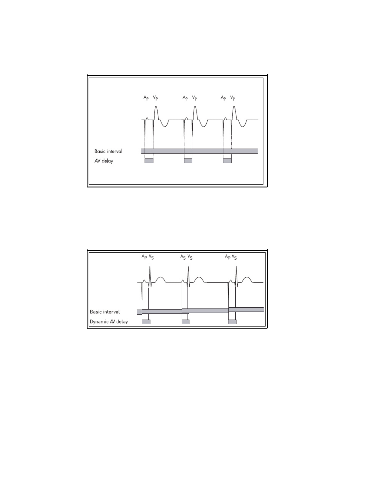
DDD Mode
In the DDD mode, the basic interval starts w ith an atrial sense (AS) or
atrial pace event (Ap) or a ventricular sense event not preceded by an
atrial event (VES = "ventricular extrasystole"). If no atrial sense event
occurs within the basic interval, atrial pacing takes place at the end of
the basic interval (See Figure 1), and the basic interval is restarted.
Page 24
24
Pacing Types – Modes
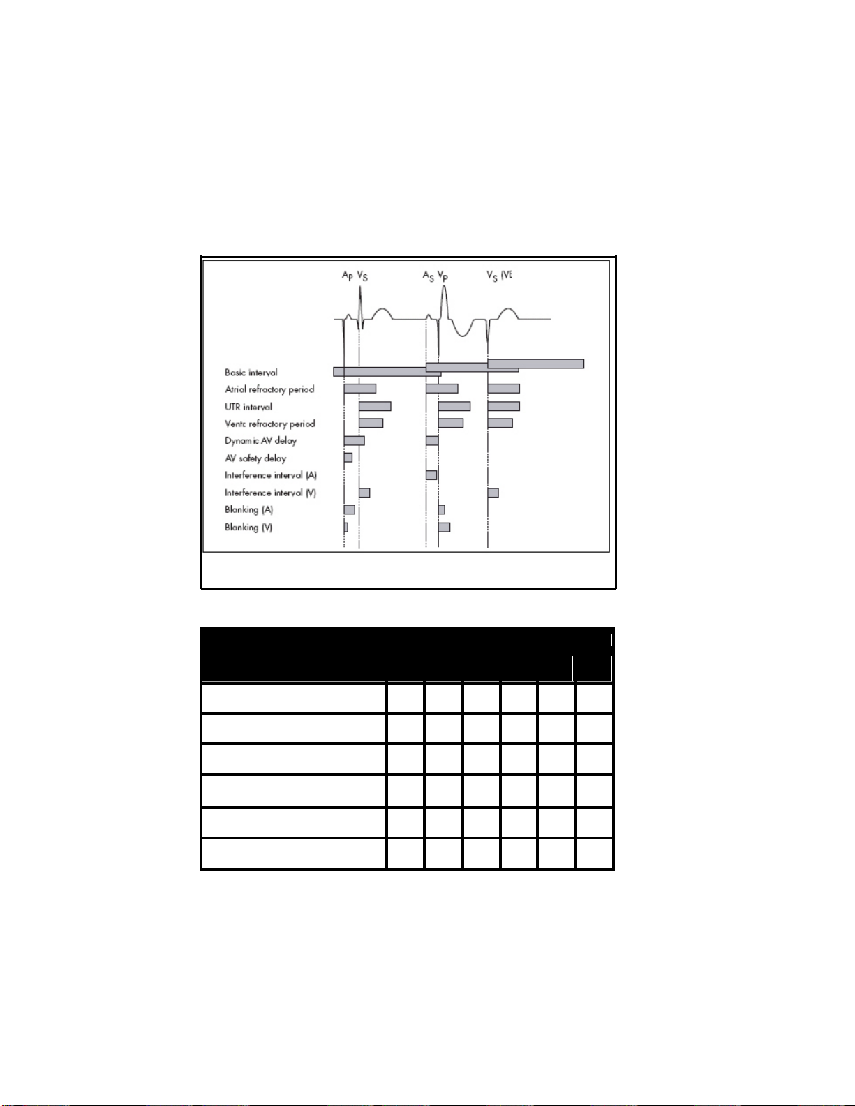
Figure 1: AV-sequential pacing in DDD mode without an intrinsic event
In the case of an atrial sensed or paced event, the AV delay starts
together with the basic interval. If a ventricular sensed event does not
occur within the AV delay, ventricular pacing is triggered at the end of
the AV delay. If ventricular sensing (VS) occurs within the AV delay, the
ventricular pulse delivery (VP) is inhibited.
Figure 2: An atrial sensed event restarts the basic interval
If atrial sensing occurs, atrial pacing is inhibited and the basic interval
is restarted (See Figure 2).
Page 25
25
Pacing Types – Modes
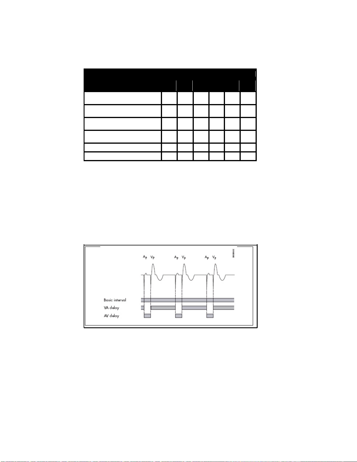
Figure 3 and Table 1 summarize the timing intervals init iated by
sensing or pacing. The table distinguishes between pacing at the end
of the AV delay (VP) or pacing at the end of the AV safety delay (VSP)
and between sensing within the AV delay (VS) or sensing outside the AV
delay (VES).
Figure 3: Start of timing intervals in the DDD mode depending on the events
that occur
Event Timing Interval
Ap As Vp Vsp Vs VES
Basic Interval (DDD)
Basic Interval (DDI)
Atrial Refractory Period
Atrial Refractory Period Extension
Upper Track ing Rate Interval
Ventricular Refractory Period
• • •
• • • •
• • •
•
• • • •
• • • •
Table 1: Timing intervals initiated by pace and sense events in DDD and DDI
modes (Vsp = v entricular safety pacing)
Page 26
26
Pacing Types – Modes
Event Timing Interval
Ap As Vp Vsp Vs VES
(Dynamic) AV Delay
AV Safety Delay
Interference Interval (A)
Interference Interval (V)
• •
•
•
• •
Blanking Period (A) • • •
Blanking Period (V) • • •
Table 1: Timing intervals initiated by pace and sense events in DDD and DDI
modes (Vsp = v entricular safety pacing)
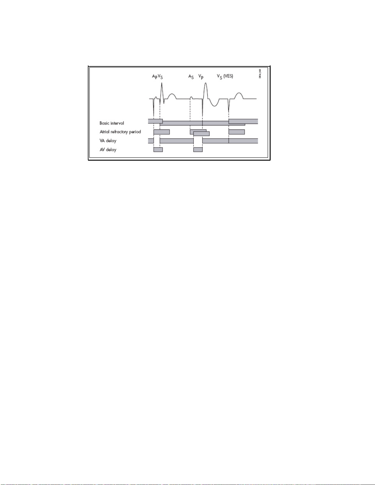
DDI Mode
In contrast to the DDD mode, the basic interval in the DDI mode does
not start with a P wave, but rather with ventricular sensed or paced
events. The VA interval is started together with the basic interval. If no
atrial or ventricular sensing occurs within the VA interval, atrial pacing
takes place at the end of the VA interval (See Figure 4).
Figure 4: AV-sequential pacing in DDI mode without an intrinsic event
Upon pacing, the AV delay is restarted. If sensing occurs, atrial pacing
is inhibited (See Figure 5). The AV delay does not start with this sense
event, but again at the end of the VA interval. Thus, P waves in DDI
mode do not trigger ventricular events.
Page 27
27
Figure 5: Inhibition of atrial pacing in DDI mode by an atrial sensed event
occurring within the VA interval. The atrial refractory period restarts at the
end of the VA interv al.
Pacing Types – Modes
DVI Mode
The DVI mode is based on the DDI mode. In contrast to the latter,
atrial sensing does not occur in DVI mode. Therefore, atrial pacing is
forced at the end of the VA delay. Ventricular sensing within the VA
interval inhibit s both the atrial and the ventricular pulse. Ventricular
sensing within the AV delay inhibits the ventricular pulse.
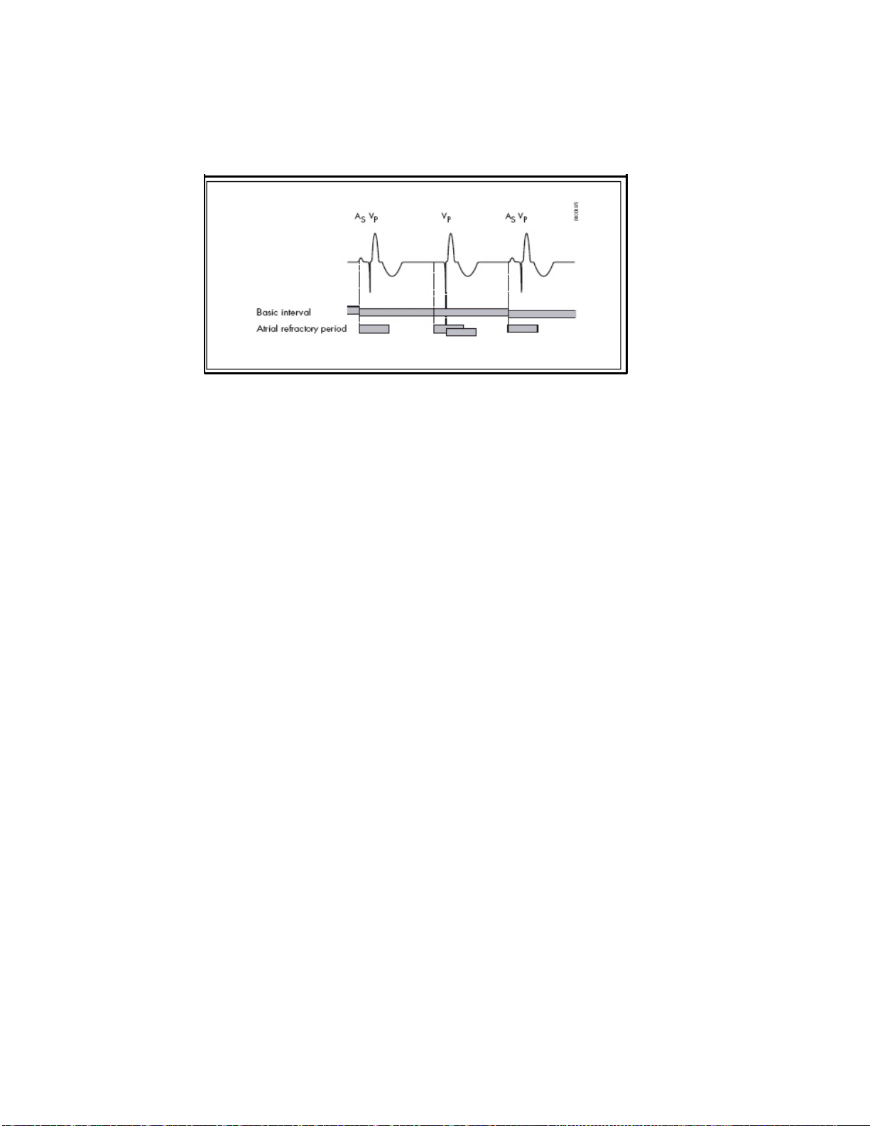
VDD Mode
The VDD mode is derived from the DDD mode. In contrast to the latter,
no atrial pacing takes place. Therefore, the basic interval starts at an
atrial sense event, a ventricular extrasystole, or at the end of the
preceding basic interval if no sense event occurs.
To prevent pacemaker-mediated reentry tachycardia, the atrial
refractory period is also started by ventricular paced events that were
not triggered by atrial sensed events (See Figure 6).
Page 28
28
Pacing Types – Modes
Figure 6: Prevention of pacemaker-mediated tachycardia in VDD mode
AAI Mode, VVI Mode
The AAI and VV I single-chamber pacing m odes are used for atrial or
ventricular demand pacing. In each case, pacing and sensing only
occur in either the atrium (AAI) or the ventricle (VVI).
The basic interval is started by a sense or pace event. If there is a
sense event before the end of the basic interval, pulse delivery is
inhibited. Ot herwise, pacing takes place at the end of the basic
interval.
AOO Mode, VOO Mode
In these pacing modes, pulses are emitted asynchronously in the
atrium (AOO) or ventricle (VOO). When using VOO or AOO mode, the
risks associated with asynchronous vent ricular pacing must be
considered.
DOO Mode
Asynchronous AV-sequential pulses are delivered in this pacing mode.
When using DOO mode, the risks associated w ith asynchronous
ventricular pacing must be considered.
Page 29

29
Pacing Types – Modes
Triggered Pacing
Triggered pacing modes correspond to the respective demand modes,
the difference being that detection of an atrial/ventricular event
outside the refractory period does not cause pulse inhibition, but
rather triggers imm ediate pulse delivery to the respective chamber.
The corresponding pacing m odes are:
Demand: DDD VDD DDI DVI AAI VVI
Triggered: DDT
DDT/A
DDT/V
However, the following differences do occur: There is no AV safety
delay in the DDT, DDI/T and DVT pacing modes. It is not necessary
since ventricular pulse inhibition because of crosstalk (ventricular
sensing of the atrial pacing pulse) cannot occur in these modes.
In the DDI/T and DV T pacing modes, the basic interval is not restarted
if ventricular sensing occurs within the AV delay.
VDT DDI/T DVT AAT VVT
DDT/A Mode, DDT/V Mode
The DDT/A and DDT/V modes are derived from the DDT mode. In
DDT/A mode, the pacemaker delivers a pulse in the atrium after every
sensed atrial event and inhibits pacing in the ventricle if required.
Similarly, in DDT/V mode, an immediate pulse in the ventricle, and if
required pulse inhibition in the atrium, follows every sensed ventricular
event.
Page 30

30
Pacing Types – Modes
VDI Mode
The VDI mode is derived from the VVI mode. In contrast to the latter,
the VDI mode allows intra-atrial events to be recorded. The timing
corresponds to the VVI mode, however. The VDI mode is designed for
measuring ret rograde conduction with the IEGM and/or the marker
function. Retrograde conduction time can be determined directly on
the programmer, or on an additional ECG recorder, as the length of
time between a ventricular pace or sense event and the subsequent
atrial sense event.
OFF Mode
In the OFF mode, pacing pulses are not delivered, except when used
with external pulse control. Without external pulse control, the OFF
mode is used for detection and morphological evaluation of the
intrinsic rhythm. With external pulse control, the OFF mode is used for
electrophysiologic studies and to combat tachycardia. The OFF mode
is only programmable as a temporary program. The pulse and control
parameters remain adjustable in the OFF mode. With the use of the
external pulse control function, the programmer triggers pacing pulses
and sensed events can be transmitted to the programmer. Note that
sensing is limited by the refractory period, whereas pacing is not.
Magnet Effect
Placing a magnet (or the programming wand) over the pacemaker
causes the built-in magnetic switch in the pacemaker to close. The
pacemaker response to magnet application is adjustable.
Note: The following functions are deactivated by magnet
application:
Page 31

31
— Recording of statistics
— Mode switching
— Automatic lead check
— AV hysteresis and rate hysteresis
— Rate adaptation
— Overdrive
— PMT protection
— VES lock-in term ination
— Active capture control (ACC)
— Rate fading
Pacing Types – Modes
Automatic Magnet Effect
During the first 10 cycles after magnet application the pacemaker
paces asynchronously at 90 ppm (at 80 ppm upon reaching the
replacement indication). Thereafter, synchronous pacing at the
programmed basic rate occurs (or at the night rate, if one has been
programmed). During asynchronous pacing, the AV delay is reduced to
100 ms if a longer interval was programmed. This avoids ventricular
fusion beats when AV conduction is intact and makes it easier to detect
the effectiveness or ineffectiveness of ventricular pacing.
Asynchronous Magnet Effect
The sensing function of the pacemaker is deactivated for the duration
of the external magnet application. During t his time, the pacemaker
paces asynchronously at 90 ppm (at 80 ppm upon reaching the
replacement indication).
Synchronous Magnet Effect
The sensing and pacing behavior of the pacemaker remains unchanged
when a magnet is placed over the pacemaker. The basic rate also
remains intact (except aft er the replacement indication has been
reached). Th e synchronous magnet effect is only important for the
follow-up and if you want IEGM recordings to be triggered by the
patient. This guarantees that the sensing function remains enabled
when the programming wand or magnet is applied, and that the
replacement indication can be monitored.
Page 32

32
Pacing Types – Modes
Summary of the Functions and Timing Intervals
of the Modes
Table 2 summarizes the functions and time intervals that apply to the
various demand pacing modes. Not included are rate-adaptive
parameters and parameters that can be programmed in all pacing
modes.
The sensitivity can always be programmed during pulse inhibition
and/or pulse triggering.
Pacing Modes Parameter
DDD
DDT
DDT/A
DDT/V
DDI
DDI/T
DVI
DVT
VDD
VDT
VDI
AAI
AAT
VVI
VVT
Basic rate
Rate hysteresis
Repetitive rate
hysteresis
Scan rate hysteresis
• • • • • • • • • • • • • • •
• • • • • • • • • • • •
• • • • • • • • • • • •
• • • • • • • • • • • •
Upper tracking rate
A pulse
duration/ amplitude
V pulse
duration/ amplitude
As inhibits Ap
As triggers Ap
As triggers Vp
Vs inhibits Vp
Vs triggers Vp
A refractory period
V refractory period
Dynamic AV delay
AV hysteresis
AV repetitive
hysteresis
• • • • • • • • • •
• • • • • • • • • •
• • • • • • • • • • • • •
• • • •
• • • •
• • • • • •
• • • • • • •
• • • • • •
• • • • • • • • • • •
• • • • • • • • • • • • •
• • • •
• • •
• • •
Table 2: Functions and timing intervals of the different pacing modes
Page 33

33
Pacing Types – Modes
AV scan hysteresis
AV safety delay
Pacing Modes Parameter
DDD
DDT
DDT/A
DDT/V
DDI
DDI/T
DVI
DVT
VDD
VDT
VDI
AAI
AAT
• • •
• • • • •
VVI
VVT
Sense compensation
V blanking period
Wenckebach
possible
Table 2: Functions and timing intervals of the different pacing modes
• • • •
• • • • • • • •
• • • •
• = present
A = atrium, atrial
V = ventricle, ventricular
Ap = atrial pace event
As = atrial sense event
Vp = ventricular pace event
Vs = ventricular sense event
Page 34

34
Timing Functions
Timing Functions
Basic Rate
The basic rate is the rate at which the pacemaker delivers pulses in the
absence of a spontaneous rhythm or if sensing is deact ivated. The
corresponding interval is called the "basic int erval" - the interval
between two pacing pulses.
In the atrial-controlled modes, the basic interval is started by an atrial
event. In the atrial-controlled dual-chamber modes, the basic interval is
also started by a ventricular extrasystole.
In the ventricular-controlled modes, the basic rate is started by a
ventricular event.
Rate Hysteresis
To preserve a spontaneous rhythm once it occurs, a rate hysteresis can
be programmed in the modes DDD(R), DDT(R), DDT(R)/A, DDT(R)/V,
DDI(R), VDD(R), VDT(R), VDI(R), VVI(R), VVT(R), AAI(R) and AA T(R). In
this case, the pacemaker, after detecting a sense event, “waits” not
only for the duration of the basic interval for a new sense event, but
also for the duration of the longer hysteresis interval before pacing
occurs. This means that the pacemaker tolerates a spont aneous
rhythm whose rat e lies below the basic rate. However, the intrinsic rate
must be higher than the rate that corresponds to the hyst eresis
interval. If a sensed event does not occur within the hysteresis interval,
a pacing pulse is delivered at the end of the hysteresis interval. The
next interval then conforms to that of the basic rate or the interval
determined by the sensor (See Figure 7).
Page 35

35
Timing Functions
Figure 7: Basic rate and rate hysteresis in DDD mode
In pacing modes DDD(R), DDT(R)/A, DDT(R)/V, DDT(R), V DD(R),
VDT(R), AAT(R), and AAI(R) the hysteresis interval starts with an atrial
sense event. In the modes DDI(R), VVI(R), VVT(R) and V DI(R) it starts
with a ventricular sense event. In modes DDD(R), DDT(R)/A, DDT(R)/V,
DDT(R), V DD(R) and VDT(R) it also starts with a ventricular
extrasystole.
The rate hysteresis is specified as the difference from the basic rate. In
rate-adaptive pacing, the hysteresis remains constant while the
hysteresis rat e follows the variable (sensor-controlled) basic rate.
Note: If the rate hyst eresis is to be used in the DDI
mode, the AV delay must be programmed shorter
than the spontaneous conduction time. Otherwise,
the pacemaker paces at the hysteresis rate instead
of the basic rate even in the absence of
spontaneous activity.
Repetitive Rate Hysteresis
The repetitive rate hysteresis helps to maintain the spontaneous
rhythm and avoid unnecessary pacing in sit uations that exceed the
basic hysteresis, such as post -extrasystolic pauses.
If such a pause occurs, the pacemaker continues to pace at the
hysteresis rat e for a programmable num ber of cycles inst ead of
immediately reverting to the basic rate (See Figure 8).
Page 36

36
Figure 8: Repetitiv e rate hysteresis
Timing Functions
An existing spontaneous rhythm is thus once again able to inhibit the
pacemaker. This prevents any worsening of the hemodynamics, as
might otherwise occur in modes such as VVI pacing. The pacemaker
supports and stabilizes the spontaneous atrial rhythm in DDD or DDDR
modes. This prevents the undesirable suppression of the spontaneous
rhythm through overdrive, especially during periods of rest. Repetitive
rate hysteresis is only activated in the presence of a stable intrinsic
rhythm, that is, when continuous inhibition by the spontaneous rhythm
has occurred during the previous 180 cycles, at the very least .
Scan Rate Hysteresis
The scan rate hysteresis promotes a spont aneous rhythm during longer
phases of pacing.
Page 37

37
Timing Functions
If scan hysteresis is activated, the pacemaker will reduce the pacing
rate temporarily to the hyst eresis rate after every 180 consecutive
atrial paced events. The number of scan intervals can be programmed
(See Figure 9).
Figure 9: Scan rate hysteresis
If no intrinsic event is detected during the scan intervals, pacing at the
basic rate is resumed (at the sensor rate in rate-adapt ive mode).
Scanning for a spontaneous rhythm is repeated after an additional 180
cycles.
Reaction to Vasovagal Syncopes and Carotid Sinus Syndrome
The scan rate hysteresis can be used in conjunction with the repetitive
rate hysteresis to treat patients with vasovagal syncopes and carotid
sinus syndrome of a primarily cardioinhibitory type. The following
programming is recommended for this purpose.
Basic rate Increased v alue, for example 90 ppm
Rate hysteresis Such that the hysteresis rate at rest is always lower
Scan rate hysteresis Enabled, with th e number of cycles set according to
Repetitive rate
hysteresis
than the intrinsic rhythm (e.g., -50)
the patient's condition
Enabled, with a low number of cycles
Page 38

Basic Rate:
Rate Hysteresis:
Scan Rate Hysteresis:
Repetitive rate
hysteresis
38
Timing Functions
Increased value, for example 90 ppm
Such that the hysteresis rate at rest is always lower than the intrinsic
rhythm (e.g., -50)
Enabled, with the number of cycles set according to the patient's
condition
Enabled, with a low number of cycles
This programming will inhibit the pacemaker until bradycardia
episodes occur. If the rate drops due to an event, the pacemaker will
pace at the hysteresis rate for the set num ber of repetition cycles (the
confirmation period). The pacemaker will switch to the higher
intervention rate to prevent possible syncope only if a spontaneous
rhythm does not occur during the confirmation period, which should be
set as short as possible. The pacemaker will scan for a spontaneous
rhythm every 180 cycles (scan rate hysteresis) to avoid long pacing
phases. If the attack has been t erminated by that time, the pacemaker
will be inhibit ed; otherwise, it will repeat the scan every 180 cycles.
Note: These patients should only be treated with a
DDD(R) system to exploit the contribution of the
atrium to ventricular filling and to overall
hemodynamics as much as possible during such
attacks.
Night Program
When the night program is activated, the pacemaker reduces its
activity during the night. This makes it possible to adapt the pacing
rate to the patient 's reduced m etabolic needs during this time.
Furthermore, VVI and VOO pacing may prevent the possible worsening
of hemodynamics.
Page 39

39
The beginning and end of the night, as well as the basic night rate, can
be programmed. At the beginning of the night period, the basic rate
and the hysteresis rate are gradually reduced to the night values. If
rate adaptation is enabled, the sensor threshold during the night is
increased by one increment (less sensitive). This prevents undesirable
rate increases – even in patients who do not sleep soundly. After the
night has ended, the pacemaker resumes its daytime pacing values.
Note: Please take into consideration that the patient may
Note: The internal clock of the pacemaker is
Timing Functions
travel to other time zones. If this is expected, the
night duration should be programmed accordingly
shorter or even deactivated.
automatically adjusted to the clock of the
programmer at every follow-up. Ensure that the
time displayed by the programm er is correct.
Refractory Period
Sensed events that occur during the refract ory period do not affect the
timing. The functions related to tachycardia behavior are an exception:
automatic mode conversion and mode switching. In these functions,
sensed events within the refract ory period are utilized for arrhythmia
detection.
In DDD(R) and VDD(R) m odes with automatic mode conversion, the
atrial refractory period (ARP) can be triggered, i.e., a sensed event
occurring in the atrial refract ory period can restart it.
In the DDD mode the ARP not only starts after atrial sensing or pacing,
but also with ventricular extrasystoles (VES). This is to prevent
pacemaker-mediated tachycardia. For the sam e reason, the ARP also
begins in the VDD mode upon ventricular pacing that was not triggered
by an atrial event, and upon VES. In the DDI mode, t he ARP starts only
after an atrial sensed or paced event.
Page 40

Valid for Cylos DR and
Cylos DR-T
40
Timing Functions
Dynamic AV Delay
The AV delay defines the period of time between an atrial event and the
subsequent ventricular stimulus. The "dynamic" AV delay lets you
optimize the AV delay for five different atrial rate ranges. The AV delay
selected for this rate is then effective depending on the current atrial
rate (the A-A interval). The dynamic AV delay is valid after atrial
detection and after sensor-driven atrial pacing. The AV delay can be
individually set for the following rate ranges:
Basic rate, < 70 ppm, 70 – 90 ppm, 91 – 110 ppm, 111 – 130 ppm, >
130 ppm.
In the non-rate-adaptive modes, an AV delay may be separately
selected for AV-sequential pacing at the basic rate. The AV delays in
the four other atrial rate ranges are then only act ive after the
corresponding atrial sensing.
In addition to the option of setting the AV delay individually for these
ranges, the programmer also offers three settings (low, m edium and
high). Refer to the table below for details. You can deactivate the
optimization feature and select fixed AV delays. In non-rate-adaptive
modes, the AV delay after atrial pace events is different from the AV
delay after atrial sense events.
Page 41

41
Timing Functions
Rate range AV delay (in ms) for
Basic rate (for nonrate-adaptive modes)
Less than 70 ppm 180 180 180
70 - 90 ppm 170 160 150
91 -110 ppm 160 140 120
111 - 130 ppm 150 120 100
Over 130 ppm 140 100 75
Table 3: Dynamic AV delays
programming the dynamic AV
delay to
Low Medium High
180 180 180
The dynamic AV delay serves to prevent pacemaker-mediated
tachycardias and supraventricular tachycardias. See also the
"Antitachycardia Functions" section.
AV Hysteresis
An AV hysteresis can be programmed to a low, medium or high setting
to promote intrinsic AV conduction. With AV hysteresis active, the AV
delay is extended by a defined time period after sensing an intrinsic
ventricular event. The long AV interval remains intact as long as an
intrinsic ventricular activity is measured during the extended AV delay.
The short AV delay interval without extension by the hysteresis value
follows after ventricular pacing.
Caution! If AV hysteresis is enabled along with the algorithm
for detecting and terminating pacemaker-mediated
tachycardias (PMT Management), the variations in
the AV delay for detection and termination of a
PMT have priority over any possible simultaneous
activation of the AV hysteresis.
Page 42

42
Timing Functions
AV Repetitive Hysteresis
In AV repetitive hysteresis, the AV delay is also extended by the defined
hysteresis value aft er the sensing of an intrinsic ventricular event. In
contrast to normal AV hysteresis, once the ventricular pace event
occurs, the long AV delay remains intact for a programmed number of
cycles. If intrinsic activity occurs during one of these repetitive cycles,
the long AV delay remains intact. Only once the repetitive cycles have
elapsed without any instances of spontaneous AV conduction does the
pacemaker switch back to the short AV delay. The AV repetitive
hysteresis hence reduces pacing when exist ing intrinsic activity is
suppressed by occasional pace events within the extended AV delay.
AV Scan Hysteresis
In AV scan hysteresis, 180 consecutive cycles are observed and if there
were only paced events and no spontaneous ventricular activity, the AV
delay is extended by the additional AV hysteresis interval. The long AV
delay remains intact for a pre-defined number of cycles. If spontaneous
AV conduction occurs within the defined number of cycles, the AV
hysteresis remains intact. The short AV delay interval resumes only
when no ventricular event has been detected within the defined number
of cycles and instead every one of these cycles ends with a pace. The
cycle counter once again begins counting the consecutive cycles in
which there was pacing. Intrinsic ventricular events (excluding VES)
reset the counter to zero. AV scan hysteresis hence reduces pacing in
situations in which intrinsic conduction exists but does not fall within
the defined AV delay.
Page 43

Purpose
Description
43
Timing Functions
Negative AV Hysteresis
In individual cases it can be necessary to promote ventricular pacing
and allow the least possible amount of conductions of the atrial sinus
rhythm. This can be especially necessary for patients with hypertrophic
obstructive cardiomyopathy (HOCM).
With a sensed ventricular event (Vs), the function decreases the AV
delay and thereby promotes ventricular pacing. With a conventional
positive AV hysteresis, in contrast, the AV delay is increased to support
sinus rhythms.
Negative AV hysteresis is optional. It is possible to program the
negative AV hysteresis together with the negative AV repetitive
hysteresis. This ensures that the pacemaker paces with the shorter AV
delay for a programmable number of cycles when a sensed event
occurs.
The following table shows the correlation between the st andard values
of the AV delay and the negative AV hysteresis:
AV Delays (Standard) Negative AV Hysteresis
100 100
120 100
130 100
140 100
150 100
160 120
170 120
180 130
190 140
200 150
225 170
250 180
300 200
Table 4: Negative AV Hysteresis
Page 44

44
Timing Functions
Sense Compensation
For hemodynam ic reasons, it is desirable t o maintain a constant period
between an atrial and a ventricular contraction and to adjust it to
physiologic conditions. To this end, sense compensation can be used
to shorten the AV delay after atrial sensing. You can program values of
-15 to -120 ms for the sense compensation. In this case, the AV delay
after atrial sensing is shorter than it would be following atrial pacing
according to the value you have set. The AV delay after atrial pacing
then corresponds to the programmed AV delay.
Blanking Period
Atrial Blanking Period
The atrial blanking period is started after a ventricular pace (see Figure
10). Atrial sensing does not occur during the atrial blanking period.
This prevents atrial sensing of ventricular pacing (a phenomenon
known as “crosstalk”).
Ventricular Blanking Period
The ventricular blanking period is started after an atrial pace (see
Figure 10). During the ventricular blanking period, ventricular sensing
does not occur. This prevents ventricular sensing of atrial pacing (a
phenomenon known as “crosstalk”).
Programmable Values
The following values can be programmed for the blanking periods:
• Ventricular blanking period from 16 to 72 ms
• Atrial blanking period from 32 to 72 ms
Page 45

45
Note: It is recommended that the lowest possible values
Note: It is also recommended that the selected values be
The blanking period is aut omatically extended by one increment in
some combinations of pacing and sensing polarities in order to prevent
crosstalk. The programmer will indicate the amount by which the
blanking period has been extended.
Timing Functions
be selected, so that ventricular/atrial sensing is
ensured for the period during which
ventricular/atrial intrinsic rhythm may occur.
high enough to prevent undesired sensing of
pacing in the other chamber.
This is possible with high atrial/ventricular pulse
energies and/or high ventricular/atrial sensitivities.
Safety AV Delay
In the DDD(R), DDT(R)/A, DDT(R)/V, DDI(R) and DVI(R) pacing modes,
the safety AV delay is started with atrial pacing. If a ventricular sense
event occurs within the safety AV delay, the pacemaker paces in the
ventricle at the end of the interval (Vsp = ventricular safety pace). If the
AV delay is short er than the safety AV delay, pacing occurs at the end
of the AV delay.
This prevents ventricular pulse inhibition due to ventricular sensing of
atrial pacing (which would be crosstalk). (See Figure 10).
Page 46

46
Timing Functions
Figure 10: Ventricular blanking period and the AV safety delay
If AV sequential pacing is observed with an AV delay corresponding t o
the AV safety delay, this may be evidence of ventricular crosstalk
(recognition of atrial pulse delivery). In order to avoid crosstalk, you
can define a lower atrial pulse energy, a lower ventricular sensitivity
(assigning it a higher numerical value), and/or a longer ventricular
blanking period.
Pacing When Exposed to Interference
The pacemaker is equipped w ith interference protection to protect the
patient against undesired inhibition by non-cardiac signals. An
“interference interval” is started at the same time as the refractory
period. The interference interval is sim ilar to a refractory period of 125
ms that can be re-set . If an event is detected in one of the two
chambers during the interference interval, the interference interval is
restarted in the corresponding channel. If the detected rate exceeds
480/min (= 8 Hz), then the interference interval is continually
restarted, so that the channel remains refractory throughout the entire
basic interval. The pacemaker will then pace asynchronously at the
programmed basic rate in that particular chamber as long as the
interference persists (one example would be electrical or
electromagnetic interference). For further details, see the “Cautionary
Notes” section.
Page 47

47
Timing Functions
Depending on whether interference is sensed in either the atrium or the
ventricle, the following pacing modes will be used for the duration of
the interference:
Interference During EMI in the Mode
Atrium Ventricle Atrium and
DDD-CLS DVI-CLS DAD-CLS DOO(R)
DDD(R)(+) DVI(R) DAD(R)(+) DOO(R)
DDI(R) DVI(R) DAI(R) DOO(R)
DVI(R) DOO(R)
VDD(R) VVI(R) VAT(R) VOO(R)
VVI-CLS VOO(R)
VVI(R) VOO(R)
AAI(R)(+) AOO(R)
DDT(R) DVT(R) DAT(R)(+) DOO(R)
DDT(R)/A(+) DVD(R) DAT(R) (+) DOO(R)
DDT(R)/V(+) DVT(R) DAD(R) DOO(R)
DDI/T(R) DVT(R) DAT(R) DOO(R)
DVT(R) DOO(R)
VDT(R) VVT(R) VAT(R) VOO(R)
VDI(R) VVI(R) VOO(R) VOO(R)
VVT(R) VOO(R)
AAT(R)(+) AOO(R)
ventricle
Table 5: Interference modes
Interference During EMI in the Mode
Atrium Ventricle Atrium and
DDD(R) DVD(R) DAD(R) DOO(R)
DDI(R) DVI(R) DAI(R) DOO(R)
DVI(R) DOO(R)
VDD(R) VVI(R) VAT(R) VOO(R)
VVI(R) VOO(R)
ventricle
Table 6: Interference modes
Page 48

48
Timing Functions
Interference During EMI in the Mode
Atrium Ventricle Atrium and
AAI(R) AOO(R)
DDT(R) DVT(R) DAT(R) DOO(R)
DDT(R)/A DVD(R) DAT(R) DOO(R)
DDT(R)/V DVT(R) DAD(R) DOO(R)
DDI/T(R) DVT(R) DAT(R) DOO(R)
DVT(R) DOO(R)
VDT(R) VVT(R) VAT(R) VOO(R)
VDI(R) VVI(R) VOO(R) VOO(R)
VVT(R) VOO(R)
AAT(R) AOO(R)
Table 6: Interference modes
ventricle
Page 49

49
Pacing and Sensing Functions
Pacing and Sensing Functions
Pulse Amplitude and Pulse Width
In dual-chamber systems, the pulse amplitude and the pulse width are
independently programmable for the atrium and the ventricle.
The BIOTRONIK PAC ("Pulse Amplitude Control") system keeps all
pulse amplitudes below 8.4 V constant during the entire service time of
the pacemaker.
This means that the pacing safety margin is maintained even when the
battery voltage drops. The pulse widths also stay constant during the
entire service time of the pacemaker.
Note: If a pulse amplitude of 7.2 V or higher is
programmed and high pacing rates are attained,
output amplit udes may differ from the
programmed values, as in this case the amplitude
control may not have enough time for an exact
adjustment .
Sensitivity
The "sensitivity" parameter is used to set the pacemaker's sensing
threshold for intracardiac signals. The lower you set the value to be,
the higher the sensitivity.
When the sensitivity is high, there is a risk of the pacemaker being
inhibited by interference signals.
If bipolar leads are used, t his risk can be reduced by programming the
pacemaker for bipolar sensing. In the case of high ventricular
sensitivity values, particular attention should be paid to the possibility
of ventricular pacing being inhibited by the atrial pulse (a phenomenon
known as crosst alk). Please see the "Ventricular Blanking Period" and
"AV Safety Delay" sections for more information.
Note: The sensitivity should be programmed to less than
0.5 mV only when sensing is bipolar.
Page 50

50
Pacing and Sensing Functions
Lead Configuration
In a unipolar configuration, the negative pole (the cathode) is situated
in the heart, while the positive pole (the anode) is formed by the
housing of the pacemaker. In a bipolar configuration, both poles of the
leads are situated in the heart.
The pacemakers allow you to program separate lead polarities for
pacing and sensing.
Compared with bipolar pacing, unipolar pacing has the advantage of
being clearly identifiable on the surface ECG, and its energy
consumption is a bit lower. Because one pole is form ed by the
pacemaker housing in this case, unipolar pacing at high pulse
amplitudes can occasionally result in muscle stimulation in this area.
Because of its lower susceptibility to interference signals, i.e., skeletal
myopotentials, bipolar sensing offers a much better “signal-t o-noise-
ratio” than unipolar sensing. Therefore, you can program higher
sensitivities (which are expressed as lower numerical values).
Caution! If a unipolar lead is used in one of the chambers,
that lead configurat ion has to be programmed to
“unipolar.” Otherwise entrance and/or exit block
will result.
Continuous Measurement and Recording of Lead
Impedance
Cylos implants are also able to continuously measure the existing lead
impedance and record it as a short-term or a long-term trend.
Page 51

51
To this end, up t o 4 stimuli of 4.8 V are triggered every 1.5 hours in
order to be able to determine the impedance under defined conditions.
If an amplitude higher than 4.8 V is set, the measurement is conducted
with the preset amplitude. Impedances between 200-3000 Ohm are
considered.
Pacing and Sensing Functions
Automatic Lead Check
When this function is activated, the lead im pedance is automatically
measured with every pace. If the impedance values lie above or below
the limits for several consecutive measurements, the system
automatically switches from a bipolar to a unipolar lead configuration.
The event is stored in an impedance trend. In the case of unipolar
configuration and a measurement outside the limits, the automatic
lead check is deactivated. In both cases, a message is generated that
is displayed at the next follow-up when the pacemaker is interrogated.
The automatic lead check can be activated for both the at rium and the
ventricle. The selected mode m ust provide for pacing in the selected
chamber.
Page 52

Purpose
Description
52
Pacing and Sensing Functions
Amplitude Control (ACC)
The amplitude control function (Active Capture Control - ACC) does the
following:
• Continuously monitors for effective ventricular pacing
• Periodically determines the ventricular pacing threshold
• Verifies the stimulus response
The advantage for the patient is that pacing remains effective even
when there are changes in threshold. Because the pacing amplitude is
continuously being adjusted to the threshold, it is possible to optimally
configure the energy reserves of the pacem aker and thus ensure
reliable patient care.
The ACC function works for a ventricular rate of up to 100 bpm.
Note: Leads that generate high polarization artifact s are
not suitable for A CC.
The efficacy of a stimulus is m onitored by a beat-to-beat algorithm,
and the pacing energy is continuously adapted in the case of pacing
threshold fluctuations. The ACC function features the following subfunctions:
• Signal analysis
• Automatic pacing threshold search
• Verification of the stimulus response
Purpose
Signal Analysis
This function analyzes the signal quality of the ventricular evoked
stimulus response (when the stimulus is effective) and the polarization
artifacts (when the stimulus is ineffective). The function ensures that
only “undisturbed” or appropriat e signals are evaluated. Th e signal
analysis function works for ventricular rates of up to 100 bpm.
Page 53

Description
53
Pacing and Sensing Functions
— The device measures with a constant, maximum pacing
amplitude for a duration of 5 cycles. The AV delay is shortened to
50 ms after pace and to 15 ms after sense.
— After another 5 cycles, a second pulse is delivered with the same
amplitude 100 ms after the effective pace. This pace reaches
refractory tissue and thus does not evoke a stimulus response.
This makes it possible to determine the sole polarization
artifacts of the lead.
— The average signal from the 5 measurements is used to compare
the effectiveness of the pacing pulse (signal morphology) and to
classify it as effective or ineffective.
— If the signal quality is classified as insufficient, then the
pacemaker temporarily and automatically switches to safety
pacing until a successful measurement can be conducted.
— If insufficient signal quality is measured repeatedly, then the
function is deactivated and the pacemaker switches to
permanent safety pacing.
Purpose
Prerequisite
Description
Automatic Pacing Threshold Search
The pacing threshold search function enables the pacing threshold with
the resulting stimulus to be automatically determined.
Only after the signal quality has been successfully checked can the
pacing threshold search and amplitude adjustment functions be
executed.
The threshold is determined as follows:
— After successful verification of the signal quality, the pacing
amplitude is incrementally decreased with every second pace.
The AV delay is shortened to 50 ms after pace and to 15 ms
after sense.
Page 54

Purpose
Description
54
Pacing and Sensing Functions
— The incremental decrease of the pacing amplitude continues
until loss of capture is measured (meaning the pace is
ineffective). Th e last effective pacing amplit ude that is measured
is accepted and saved.
— After the first ineffective pace is detected, either the AV delay
(for atrial-controlled pacing) or the basic rat e (for ventricularcontrolled pacing) is changed with the subsequent pace.
If again no st imulus response is measured, the ineffectiveness of
the pacing is confirmed.
— A safety pulse with maximum pulse width is delivered after every
ineffective ventricular pace. This produces continuously effective
pacing.
Verification of the Stimulus Response
This function allows the pacing amplitude to be continuously verified.
Verification of the stimulus response is possible for a ventricular rate of
up to 110 bpm.
The pacing effectiveness is verified after each ventricular st imulus.
— When pacing is effective, any current settings are retained.
— When pacing is ineffective, a safety pace with a higher level of
energy is delivered after 130 ms at the latest. This is done at the
same amplitude but a greater pulse width.
— When a series of 3 consecut ive ventricular paces – even after the
AV delay has been changed – does not produce effective pacing,
first the signal analysis function is started and a new threshold
search is executed.
— If pacing continues to be ineffective, the pacing amplitude is
increased in order to secure effective pacing. Due to this
automatic amplitude control, it is possible t o select a smaller
safety margin, which can produce lower energy consum ption
with safe pacing.
— After the monitoring interval has elapsed, the threshold search
function is automatically executed. The pacing amplitude is set
to the threshold value plus the safety margin.
Page 55

Amplitude Control -
ACC
Minimum Ventricular
Amplitude:
Maximum Ventricular
Amplitude
Scan Period
Interval
Times of Day:
1st / 2nd Time of Day
Safety Margin:
55
Pacing and Sensing Functions
Pacing in Single-Chamber Pacemakers
In order to ensure pacing in single-chamber pacemakers during signal
analysis and threshold verification, the device paces at a rate that is 10
ppm higher than the intrinsic rate.
Programmable Parameters
ON; OFF; ATM
The "minimum ventricular amplitude" and "maximum ventricular
amplitude" param eters prevent a certain value of the ventricular
amplitude from being exceeded or undershot.
0.2...(0.1)...3.6...(0 .1)...4.8 V
2.4; 3.6; 4.8 ; 6.4 V
The search period paramet er determines the times or intervals during
which the signal quality is continuously verified and the automatic
threshold search is executed. Intervals or times can be alternately
selected.
Interval; Times of Day
0.1; 0.3; 1; 3; 6; 12; 24 hours
00:00 to 24:00 hours, min. time unit of 15 min
Safety pacing is carried out at the amplit ude of the last-measured
pacing threshold plus the set safety margin or the programmed initial
amplitude. Th e largest value of the pacing threshold influences the
safety pacing.
0.3...(0.1)..1.2 V
Page 56

Active capture control
(ACC)
ON
ATM (Active
Threshold Monitoring)
Option
OFF
56
Pacing and Sensing Functions
Options for the ACC Function
The following options are available for the amplitude control function:
ON; OFF; ATM
This option activates all sub-functions: The pacing threshold is
monitored and recorded, and the pacing energy is continuously
adapted. This is done with the following:
— Signal analysis
— Automatic pacing threshold search
— Verification of the stimulus response
The threshold is monitored and recorded at programmable time
intervals. This is done with the following:
— Signal analysis
— Automatic pacing threshold search
Therefore, there is no continuous adaptation of the pacing amplitude.
This setting deactivates the entire amplitude control function.
Caution! When selecting the ATM or OFF options, m ake sure
that a sufficient safety margin is selected when
setting the pacing amplitude since there is no
automatic tracking of the pacing amplit ude for
these options.
Page 57

OK
OFF
Deactivated
Unconfirmed
High pacing threshold
57
Pacing and Sensing Functions
ACC Status
It is possible to display inform ation via the stat us of the Active Capture
Control (ACC) function. The following stat uses are possible:
— OK
— OFF; the following is displayed: "---------"
— Deactivated
— Unconfirmed
— High pacing threshold
Shows that the ACC and ATM functions are activated and operating
properly.
Shows that ACC and ATM have been deact ivated by the user.
After a maxim um of 25 activation attempt s per day, the function is
switched off by the implant, and the "Deact ivated" status is displayed.
The programmer's print out displays the reason for the deactivation:
— Insufficient signal quality
— Stimulus is frequently ineffective
— Initial test was not successful
— Implant is in ERI m ode
This status is displayed after the ACC function has been activated by
the user. Subsequently, the signal analysis and pacing threshold
search sub-functions are st arted. While these functions are running,
the status "Unconfirmed" is displayed.
Note: Re-interrogate the implant t o confirm the status.
After the sub-functions have run successfully, "OK" is displayed. Th e
ACC function is working properly.
If the recorded pacing threshold is higher than the maximum ACC
amplitude you have set, it is not possible to conduct signal analysis or
measure the pacing threshold. In this case, the user will see – on the
programmer display – a message indicating the need to increase the
maximum ACC amplitude.
Page 58

Purpose
58
Pacing and Sensing Functions
Lead Detection and Auto-Initialization
Lead Detection
The lead detection function allows the implant to recognize the
connected leads as early as during implantation. This is also the basis
for being able to activate the auto-initializat ion function.
When the connect ed leads have been successfully detected, the pacing
and sensing polarities are aut omatically set. This depends on the type
of leads connected (be they unipolar or bipolar). The pacemaker uses
the lead impedance as a basis for the automatic polarity setting.
The pacemaker goes through the following phases:
— An initial lead detection
— Lead polarity is recognized
— Confirmation
The Initial Lead Detection
To detect a lead, the implant (depending on the type) provides unipolar
pacing both in the atrial and ventricular channel and measures the
impedance of each stimulus. If intrinsic events are detected, they
trigger a pulse in the same chamber in which the event was detected.
This mimics the pacing response of an implant in the DDT mode. If the
measured impedances lie within 200-3000 Ohm, the lead is considered
detected.
Recognizing Lead Polarity
After successful detection of the lead, the im plant switches to bipolar
pacing. The impedance is also m easured during pacing. If it lies
between 200-3000 Ohm, a bipolar lead is considered confirmed.
Page 59

59
If the impedance lies outside of this range, the implant switches to
unipolar pacing. A unipolar lead is then confirm ed.
Any sense event occurring during the phase for recognizing lead
polarity triggers a stimulus in the same chamber. This allows the
impedance to be measured.
Pacing and Sensing Functions
The Confirmation Phase
After successful lead detection and detection of the lead polarity, an
implantation confirmation time of 30 minut es is started. Upon each
stimulus, the prior detected status must be confirmed. If this occurs,
lead recognition is successfully concluded.
The pacing pulse is as a rule inhibited when there are intrinsic cardiac
events. If intrinsic cardiac events are detected during the confirmation
phase, a stimulus is triggered every 10 minutes in the atrium and
ventricle to determine the lead impedance.
If there is no confirmation of the prior detected status, the initial lead
detection is restarted.
Purpose
Auto-Initialization
A few implant functions are automatically act ivated by the autoinitialization function. A prerequisite is the successful detection and
confirmation of the connected leads (in both chambers in the case of
dual-chamber implants).
Page 60

60
Pacing and Sensing Functions
select lead polarity
implantation confirm ation 30
activating functions
statistics
standby
threshold
monitoring
Figure 11: Implant functions that are activated by auto-initialization
PMT
protection
During auto-init ialization, the implant activates the following functions:
— Statistics
— ATM (the threshold recording feature of the ACC function)
— Mode switching
— PMT managem ent
— Closed Loop Stimulation standby mode, m eaning that the
function has been complet ely initialized and deactivated
Note: If the implant parameters have been changed in
the factory program prior to implantation, the autoinitialization function can no longer be executed. In
this case, only the lead detection function can be
run. Exception: Patient data can always be
configured regardless of the auto-initialization
function.
Note: The lead detection and aut o-initialization functions
can be run in the ventricle only w ith singlechamber pacemakers.
Page 61

CLS is activated
CLS is not activated
61
Pacing and Sensing Functions
CLS Standby M ode
CLS Standby Mode is where, after auto-initialization, Closed Loop
Stimulation is fully installed but deactivated. When the implant is
interrogated for the first time, Closed Loop Stimulation can be
activated. The CLS Standby Mode entails the following:
— Closed Loop Stimulation has been installed, but is deactivated.
— Until CLS is activated, the implant will pace at the basic rate.
— During the first implant interrogation, the user can activat e
Closed Loop Stimulation.
Activating CLS after the first interrogation means the following
parameters have been set:
— DDD-CLS mode for dual-chamber implants or VVI-CLS mode for
single-chamber implants.
— AV delays and AV hystereses are automatically optimized for
CLS.
When Closed Loop Stimulation has not been activated after the first
follow-up, the following parameters are automatically set:
— DDD mode for dual-chamber implants or VVI mode for single-
chamber implants.
— The AV delays from the factory program are activated. AV
hystereses are turned off.
Programmable Parameters
In addition to activating and deact ivating the entire function, the subfunctions of lead detection can be activated individually.
Note: Patient data can always be configured regardless
of the auto-initialization function.
Page 62

Auto-Initialization
62
Pacing and Sensing Functions
Note: The auto-initialization function can only be
accessed before implantation. After the pacemaker
has been implanted and the auto-initialization
function has been run, this parameter is no longer
displayed on the Parameters screen.
Note: If the implant is interrogat ed while auto-
initialization is still running, the programmer will
show a message indicating this.
ON; OFF; Lead Detection
Page 63

63
Antitachycardia Functions
Antitachycardia Functions
Overview of antitachycardia functions:
• Upper tracking rate
• Tachycardia mode
• Tachycardia response
- mode conversion and
- mode switching
• PMT management
• Preventive overdrive pacing
• VES Lock-in Protection
Upper Tracking Rate
In atrial-controlled dual-chamber modes, the upper tracking rate, along
with the atrial refractory period, determines the maxim um P-wavetriggered ventricular rate.
In all the triggered modes, the upper tracking rate lim its the pacing
rate triggered by sense events.
Caution! The upper tracking rate must be selected so that it
can be tolerated by the patient for an extended
period of time. The upper tracking rate determines
the minimum interval between a sense or pace
event and the subsequent atrial or ventricular pace
event. A decrease of the pacing interval to that of
the interval corresponding t o the upper rate may
be initiated - also at rest - for example, by
detection of atrial extrasyst oles, muscle potentials,
or other interferences. Therefore, programming a
low upper tracking rate may be indicated for
patients with increased vulnerability.
Page 64

64
Antitachycardia Functions
Tachycardia Mode
The resulting tachycardia mode (either 2:1 or Wenckebach) is
automatically displayed, depending on the combination of selected
parameters.
A response similar to Wenckebach block (the WRL mode) results if the
selected upper tracking rate is lower than the rate corresponding to the
atrial refractory period. If the upper tracking rate is exceeded in the
WRL mode, the AV delay is continually prolonged so that the
ventricular pacing rate does not exceed the programmed upper
tracking rate.
Extension of the AV delay is interrupted as soon as a P w ave occurs
before the end of the extended AV delay initiated by the preceding P
wave. In this case, the corresponding ventricular pulse is inhibited. If
the atrial rate is only slightly above the upper rate, then a 6:5 block, for
example, is the result.
Higher atrial rates produce higher degree blocks. If the length of the
atrial cycle eventually becomes shorter than the programmed atrial
refractory period, then a 2:1, 3:1, etc. block results.
Figure 12: Wenckebach -typical pacing behavior
If the selected upper tracking rate exceeds the rate corresponding to
the atrial refractory period, the maximum P-wave-triggered ventricular
rate results exclusively from the atrial refractory period, not from the
programmed upper tracking rate. If the length of the atrial cycle is
shorter than the programmed atrial refractory period, a 2:1 block, then
a 3:1 block, etc., will result before the upper tracking rate is reached in
the ventricle (DDD mode, 2:1 mode).
Page 65

65
The extended AV delay in the WRL mode and the associated
desynchronization of the atrium and ventricle increase the likelihood of
detecting retrograde P waves. This should especially be considered if
the dynamic AV delay is to be used for preventing or terminating
(pacemaker-mediated) reentry tachycardia, since the WRL mode
deactivates the dynamic AV delay when the upper rate is exceeded.
(See also PMT Management.)
If the spontaneous atrial cycle is shorter than the upper rate interval in
a rate-adaptive mode, the resulting pacing rate will depend on whether
the 2:1 rate has been exceeded or not. If this is the case, the
pacemaker will use the sensor rate as the pacing rate.
If the 2:1 rate is not exceeded, t he pacem aker will use a rat e that lies
between the sensor rate and the rate determined by the atrial
refractory period. In the latter case, the cycle length switches between
the sensor-defined interval and a shorter interval, which is at minimum
the length of the ARP. Response then depends on the ratio of the atrial
rate to the sensor rate and the atrial refract ory period.
Antitachycardia Functions
Minimum PVARP
This paramet er enables the programming of a minimal value for the
PVARP and can be activated by the physician as an additional option.
When the parameter is activated, the respective PVARP value is
displayed on the programmer, approximately corresponding to the ARP
minus the highest possible value of the set dynamic AV delay.
In Wenckebach mode, the parameter can provide additional protection
against PMTs.
Page 66

66
Antitachycardia Functions
Tachycardia Behavior
Cylos offers a choice of two algorithms that effectively suppress atrial
tachycardia from being conducted to the ventricle. At the start of a
tachycardic episode, the pacemaker aut omatically switches from an
atrial-controlled t o a ventricular-controlled m ode.
The following functions are available:
• Automatic Mode Conversion
• X/Z-out-of-8 Mode Sw itching
Automatic Mode Conversion
This option is available in the atrial modes DDD(R) and VDD(R) as well
as in DDT(R)/A and DDT(R)/V modes. In t he case of atrial tachycardias
-- when the P-P interval is shorter than the ARP (the atrial refractory
period) – there is an automatic conversion to a mode without atrial
control. If the pacemaker is in DDD(R), DDT(R)/A, or DDT(R)/V mode,
it converts to DVI(R); if it is operating in V DD(R) mode, it converts to
VVI(R). This procedure prevents P-wave-triggered ventricular pacing
during tachycardia.
When mode conversion is disabled, an atrial sensed event within the
refractory period does not trigger an interval. In activated mode
conversion, however, an atrial sensed event within the refractory period
triggers a restart of the refractory period. The basic interval and the AV
delay are not rest arted. If the coupling int erval between the consecutive
P waves becomes shorter than the atrial refractory period, the atrial
refractory period will be continuously restarted. This m eans that the
pacemaker remains refractory in the atrium during the entire basic
interval (see Figure 13).
Page 67

67
Antitachycardia Functions
Figure 13: In DDD mode without mode conversion (shown in upper graphic),
every second P wave triggers a ventricular pace during an atrial tachycardia.
In the DDD mode with mode conversion (shown in the lower graphic), an
atrial sensed event occurring in the atrial refractory period restarts the atrial
refractory period without the basic interval being restarted. This results in
DVI response for the duration of the atrial tachycardia.
This leads to non-P-wave-t riggered AV-sequential pacing at the basic
rate for the duration of the atrial tachycardia. In DDD, DDT/A and
DDT/V modes, the pacemaker paces in the atrium and ventricle; in
VDD mode it paces only in the ventricle.
In rate-adaptive modes, the pacemaker paces at the sensor rate during
atrial tachycardia.
Page 68

68
Antitachycardia Functions
Mode Switching with X/Z-out-of-8 Algorithm
This X/Z-out-of-8 algorithm can be used to program activation and
deactivation criteria. This prevents, for example, unnecessary mode
oscillations in the case of atrial extrasystoles or unstable atrial signals.
In addition, this algorithm can be employed to determine the speed at
which a de- and resynchronizat ion of ventricular depolarizat ion takes
place. This intervention rate can be programmed within a range from
100… (10)... 250 ppm.
The postventricular atrial blanking (PVAB) period after a ventricular
event can be programmed in a range from 50 – 200 ms. This prevents
any ventricular events from being registered in the atrial channel.
When an atrial tachycardia is detected, the pacemaker aut omatically
switches to a non-atrial-controlled mode: from DDD(R) to DDI(R), from
DDD(R)+ to DDI(R), or from VDD(R) t o VDI(R) as well as from DDT(R)/A
and DDT(R)/V to DDI(R).
The mode switch can be programmed so that you can switch from a
non-rate-adaptive mode to a rate-adaptive mode, and vice versa. This
serves to prevent an undesirable rate drop to the basic rate in case of
physical stress.
An atrial tachycardia is considered sensed when the so-called X-out-of8 conversion criterion has been fulfilled. The X value can be
programmed in the value range (X = 3... (1)...8).
Detection is based on the continual evaluation of the last 8 atrial
intervals. When X out of 8 intervals reveal an atrial rate that lies above
the programmed intervention rate, then the conversion criterion is
fulfilled and mode switching automatically follows.
The pacemaker works in the programmed non-atrial mode until the
switch-off criterion (Z out of 8) has been fulfilled. The Z value can be
programmed in the value range (Z = 3... (1)...8). Likewise, the last 8
consecutive at rial intervals are continuously evaluated. When Z out of 8
intervals lie below the programmed intervention rate, the atrial
tachycardia is considered to be over, and the pacemaker automatically
switches to the originally programmed atrial-controlled m ode.
The X or Z counter is reset to zero after every completed switching.
Page 69

Basic Rate during
Mode Switching
69
Antitachycardia Functions
Basic Rate during Mode Switching
It is possible to set a higher basic rate during mode switching, in order
to lessen undesirable hemodynamic conditions during mode switching.
This basic rate can be programmed to a higher value than the standard
basic rate, which leads to a slight increase of the cardiac output.
Programmable parameters:
+5...(5)...+30 ppm
Note: In the CLS modes, the Closed Loop rate is slowly
reduced to the sensor rate during mode switching.
If no rate-adaptive mode has been set for mode
switching, the CLS rate is slowly reduced to the
basic rate for during mode switching.
2:1 Lock-in Management
Description
When high atrial rates occur (such as during atrial flutter) in
conjunction with a relatively large AV delay, every other P wave may
regularly fall in the atrial far-field blanking (FFB) period. In this case,
the implant only detects half of the preceding atrial rate.
Page 70

Effects on Mode
Switching
70
Antitachycardia Functions
The implant behavior thus resembles a 2:1 block. The implant paces in
the ventricle at a rate that corresponds to one-half of the atrial rate. At
very high atrial rates, this can produce high ventricular rates that are
physiologically unsuitable.
Example: If at rial flutter at a rate of 280 bpm takes place, then the
pacemaker paces with a vent ricular rate of 140 ppm.
This phenomenon is called 2:1 lock-in and can cause the patient severe
problems in cases of long atrial flutter episodes.
In such a 2:1 sit uation, the Mode Switching function may not start at
all or only start at a very high rate, even though the function is
necessary. Therefore, the purpose of this function is to ensure the
effective use of mode switching.
To terminate 2:1 lock-in behavior, the AV delay is extended by a value
equal to the far-field blanking period, and the device m ay switch to a
ventricular-cont rolled pacing mode. The algorithms for the 2:1 lock-in
behavior have been designed as follows:
— A phase where the behavior is suspected
— Confirmation of such
— Termination
When 2:1 Lock-In Behavior is Suspected
The following criteria must be fulfilled in order for there to be a 2:1
situation:
— Eight (8) consecutive VpAs intervals must occur
— The actual vent ricular rate must be higher than 100 ppm
— The average deviation of the 8 VpAs intervals must lie within the
tolerance lim it of the 2:1 lock-in stability criterion
When these three conditions are m et, the 2:1 lock-in situation is
considered confirmed.
Page 71

71
Antitachycardia Functions
Confirmation of 2:1 Lock-In
Detection of a 2:1 situation is determined as follows:
— The AV delay is lengthened for one cycle by a maximum of 300
ms, in order to confirm the 2:1 lock-in situation. In this manner,
events that previously fell within the blanking period are detected
by the implant as atrial refractory events. At the same time, the
minimum PVARP function is activated for the time of the AV
delay extension.
Termination
Termination is initiated as follows:
— If the As-Ars interval attains the mode switch rate, the implant
immediately switches to the previously selected ventricular mode
(without first waiting for the criteria for X/Z-out-of-8 mode
switching).
— If the rate that corresponds to the As-Ars interval is greater than
the mode switching rate, then the AV delay is reduced to the
current value in increments of 50 ms.
2:1 Lock-in Protection
Programmable Parameters
The following parameter is displayed on Mode Switching screen, where
you can make the necessary sett ings.
ON; OFF
PMT Management
The following features are provided for the prevention, detection, and
termination of pacemaker-mediat ed tachycardias (PMT):
PMT is prevented by
— Restarting the basic interval and the atrial refractory period
— Extending the atrial refractory period
PMT protection is offered by
— PMT detection
— PMT termination
Page 72

72
Antitachycardia Functions
PMT Prevention
Pacemaker-mediated tachycardia is generally triggered by ventricle
depolarization that is out of synchrony with atrial depolarization, e.g.,
as would be the case in ventricular extrasystoles (VES). The
tachycardia is maintained retrogradely by VA conduction coming from
the ventricle depolarization due to pacing and antegradely by P-wavetriggered ventricular pacing.
In order to prevent PMT in cases where there is ventricular sensing
without a preceding atrial event, the pacemakers restart the basic
interval and the atrial refractory period (ARP). If an atrial refractory
period extension has been programmed, this is additionally prolonged
even further after a VES. A retrograde P wave with a VA conduction
time shorter than the ARP cannot trigger a ventricular pulse and hence
cannot trigger a PMT (see Figure 14).
Figure 14: VES starts the ARP to prevent pacemaker-mediated tachycardia
Atrial Refractory Period Extension
In the case of a programmed atrial refractory period extension, the
atrial refractory period is extended by the programmed value after a
ventricular event, if the event
• is a ventricular sensed event without a preceding atrial event (VES);
pacing modes: DDD(R), DDT(R), VDD(R), VDT(R),
• is a ventricular pace event that has not been triggered by a P wave;
pacing modes: VDD(R), V DT(R).
Page 73

73
An atrial refractory period extension might be necessary in the case of
a short atrial refractory period in conjunction with a long VA
conduction period in order to prevent the triggering of a PMT by
asynchronous ventricular depolarizations.
Antitachycardia Functions
PMT Protection
Pacemaker-mediated tachycardias can also be caused by artifacts and
atrial extrasystoles. In such cases, the PMT protection algorithm
provides functions for both reliable detection as well as termination of
PMTs. In this way the hemodynam ically more favorable AV
synchronization can rapidly be reestablished.
PMT Detection
The period between a ventricular event and the sensing of a retrograde
P wave is designated as the VA delay or retrograde conduction: Vp-As
interval (Vp = ventricular pace, As = a sensed atrial event). The VA delay
is a programmable parameter (VA criterion) and can be set between
250 and 500 ms.
A pacemaker-mediated tachycardia is recognized by the sensing
algorithm when the following criteria are satisfied:
• Eight consecutive Vp-As intervals must be shorter than the
programmed VA delay.
• The average standard deviation of the eight Vp-As intervals must lie
within the tolerance limits of the PMT stability criterion.
Page 74

74
If these two conditions are met, the pacemaker automatically extends
or shortens the AV delay by a defined value. If the resulting Vp-As
interval remains constant, the PMT is considered confirmed. The
algorithm for terminating the PMT is automatically started.
Note: In cases where a low upper tracking rate and long
Antitachycardia Functions
AV delays have been programmed, pacing rates
slightly above the UTR may occur for a few cycles.
PMT Termination
The PMT is terminated by ext ending the total atrial refractory period
(TA RP) for a pacing cycle. This interrupts the retrograde conduction
loop and hence the PMT. Consequently, the PVARP must be longer
than the retrograde conduction period after ventricular pacing or
sensing. The duration of the PVARP depends on the duration of the
TA RP used in the systems and on the AV delay (PVARP = TARP minus
the AV delay).
Note: A safety interval of 300 ms protects against
competitive pacing and prevents the atrial pulse
from reaching refractory and/or vulnerable tissue.
This safety interval cannot be programmed and is only active when the
PMT function is active.
Preventive Overdrive Pacing
Atrial overdrive pacing is a preventive measure to reduce the incidence
of atrial tachycardias. Numerous clinical studies and publications
indicate a decreased risk of developing atrial tachycardias. The
overdrive algorithm effects atrial overdrive pacing and ensures pacing
at a rate that is slightly above the intrinsic sinus rate. Atrial overdrive
pacing thereby minimizes the number of detected atrial events. The
overdrive mode is available in the modes DDD(R)+, DDT/A(R)+,
DDT/V(R)+, AAI(R)+ and AAT(R)+.
Page 75

75
Antitachycardia Functions
Incremental Rate Increase and Decrease
Each time an atrial event is sensed, the pacing rate is increased by a
programmable increment (see Figure 15). This overdrive increment can
be set to either low (approx. 4 ppm), m edium (approx. 8 ppm), or high
(approx. 12 ppm ). If the intrinsic rate does not continue to rise after a
programmable number of cycles (the overdrive pacing plateau), t he
overdrive pacing rate is reduced in increments of 1 ppm. The drop in
rate occurs each time after the programmed number of cycles has
been completed (see Figure 16). Values between 1 and 32 cycles can
be assigned to the overdrive pacing plateau.
Figure 15: Incremental rate increase in preventive overdrive pacing
The pacing rate is reduced until the next atrial event is sensed.
Subsequently, the overdrive cycle begins again with the rat e increase.
Page 76

76
Antitachycardia Functions
Figure 16: Incremental rate reduction with preventive overdrive pacing
Safety Function of the Algorithm
Preventive overdrive pacing provides various safety functions which
are, for example, effective for high atrial rates:
• When the programmed maximum overdrive rate (MOR) is exceeded,
such as in the case of atrial tachycardias, then the algorithm is
automatically deactivated. Should the rate fall below the MOR, the
overdrive algorithm is reactivat ed.
• The function is likewise deactivated when the average atrial rate of
the last 64,000 cycles exceeds the average safety rate (ASR). In this
case, the pacing rate is incrementally decreased to the basic rate.
The ASR is dependent on the programmed basic rate and the MOR.
When the average atrial heart rate falls below the ASR, preventive
overdrive pacing is reactivated.
The overdrive remains permanently switched off after the fourth
deactivation due to the ASR being exceeded. The overdrive mode can
be reactivated only after the next interrogation of the pacemaker.
Page 77

Purpose
Description
77
Caution! When programming the DDD(R)+ overdrive mode,
Antitachycardia Functions
you should check whether a pacemaker-mediat ed
tachycardia could be triggered on the basis of the
selected pacemaker program, and whether at rial
overdrive pacing m ight then develop.
If this is the case, we recommend programming
the maximum overdrive rate (MOR) for the atrial
overdrive to a value which is lower than the
expected rate of the pacemaker-mediated
tachycardia.
VES Lock-in Protection
Terminating VES lock-in behavior by an atrial stimulus after detecting a
P wave during the refractory period. This function is particularly
suitable for patients with first-degree AV block.
When ventricular extrasystoles (VES) occur, the following implant
behavior can occur:
— When VES occur, the basic interval and atrial refractory period
are restarted. This enables the P waves to fall within the atrial
refractory period.
— As a result, no ventricular pacing pulses are triggered by the P
waves. This implant behavior is termed VES lock-in.
— To terminate this VES behavior, an atrial st imulus is emitted
during the refractory period after the atrial sense event t o
resynchronize the implant with the cardiac activity.
The VES lock-in protection function can be optionally activated, and
you have the option to set the number of detection cycles.
Page 78

78
Rate Adaptation
Rate Adaptation
Cylos uses two completely separate principles for rate adaptation:
• Rate adaptation by an accelerometer
• Physiologic rate adaptation using Closed Loop Stimulation
The programmable rate-adaptive modes fall into the following
categories:
Rate Adaptation
Closed Loop
Stimulation
physiological
rate adaptation
DDD-CLS
VVI-CLS
Table 7: Overview of rate adaptation
Accelerometer-based
activity modes
DDDR
DDIR
DDITR
DDTR
DDTRA
DDTRV
DVIR
DVTR
VDDR
VDTR
VDIR
VVIR
VVTR
V00R
AAIR
AATR
A00R
D00R
atrial overdrive
pacing
+
DDDR
+
DDTR
+
DDTRA
+
DDTRV
+
AAIR
AATR+
Accelerometer-Based Rate Adaptation
Sensor-controlled rate adaptation allow s an adjustment of the pacing
rate to changing m etabolic needs at rest and during exert ion. The
pacing rate increases at the onset of exercise to the sensor-determined
rate. It slowly returns to the basic rate when exercise is no longer
detected.
Page 79

79
The pacemakers are equipped with an accelerometer that is integrated
into the hybrid circuit. This sensor produces an electric signal that is
constantly processed by analog and digital signal facilities. If a rateadaptive mode is programmed, then this effects an adjusted increase
of the basic rate, depending on the exertion level of t he patient. With
the sensor being integrated in the hybrid circuit, it is not sensitive to
static pressure on the pacemaker housing.
The sensing and inhibition function remains activated during sensorcontrolled operation. In case of high pacing rates, however, the
refractory periods may cover a majority of the basic interval, resulting
in asynchronous operation.
Convenient diagnostics features allow you to quickly set individual and
optimal rate adaptation for the patient (see the section on “Follow-up
Options” for more details).
Rate Adaptation
Physiologic Rate Adaptation (The CLS Feature)
How Closed Loop Stimulat ion Works
The contraction dynamics of the myocardium vary depending on the
patient's exertion. These changes are characteristic, allowing Closed
Loop Stimulat ion to determine a pacing rate that is patient -specific
and physiologically appropriate. This also applies to times when the
patient is emotionally stressed.
Page 80

80
Rate Adaptation
The pacemaker evaluates the dynamics of the myocardial contraction
quickly after vent ricular contraction. Impedance is measured via a
ventricular lead and is largely dependent on the specific conductivity of
a small volum e of tissue surrounding the electrode tip.
Changes in impedance are characteristic of ventricular contraction and
are directly proportional to heart stress. The pacemaker calculates the
necessary pacing rate by measuring the current impedance and
comparing it with impedance data that was measured at rest . CLS is
able to immediately respond to exertion by using contractility as input
for rate adaptation. There is therefore no need to combine CLS with
accelerometer-based rate adaptation.
Closed Loop Stimulation is self-calibrating and automatically adjusts to
the patient's situation within just a few minutes. Typically, there is no
need to manually fine-tune the system. Automatic fine-tuning
continually occurs throughout the entire service time of the
pacemaker.1
It may be necessary to adjust the CLS in individual cases, as when a
patient is extremely active or inactive.
1
Among other things, the baseline impedance curves used for comparison are regularly
updated by pacing cycles with extended or reduced AV delays.
Page 81

81
Rate Adaptation
Individually Adjusting CLS Parameters
The following parameters can be individually adjusted w ith the
“extended CLS settings”:
• The required VP
• The CLS dynamics
• Dynamic runaway protection
The Required VP
In the DDD CLS mode, the default setting includes AV hysteresis to
support existing adequate intrinsic conduction. For patients with
inadequate or non-existing intrinsic conduction, it may be necessary to
turn off AV hysteresis. To do this, turn on the parameter [required VP].
CLS Dynamics
The factory settings for Closed Loop Stimulation provide most patients
with optimum rate dynamics. Typically, there is no need to make
adjustment s.
The rate profile resulting from Closed Loop Stimulation can vary
greatly from patient to patient. In individual cases, the rate dynamics
can be optimized if the rate distribution is inadequate.
The [CLS Dynamics] parameter influences the pacemaker-internal
target rate, which is dependent on two other pre-set parameters: the
basic rate and the maxim um closed loop rate. The pacemaker
internally controls rate adaptation so that 20% of the pace events are
always above the internal target rate. If CLS dynamics are
reprogrammed to a higher value, then the rate distribution includes
higher rates, and vice versa: lower programmed values yield rate
distribution with lower rates.
Page 82

82
Dynamic Runaway Protection
This paramet er sets the pacing rate attainable during rest to a
programmable value,1 for example 20 ppm, above the preset basic
rate. This suppresses any non-specific rate fluctuations at rest without
limiting the rate adaptation under mental st ress. In cases where
runaway protection is not clinically appropriate, this feature can be
turned off.
Rate Adaptation
The CLS Safety Feature
The pacemaker regularly checks internally that everything needed for
correct Closed Loop Stimulation is available. If one of these
requirements is not met, then Closed Loop Stimulation is interrupted,
and the pacing rate is lowered t o the sensor rate. As soon as all
requirements are met, Closed Loop Stimulation automatically restarts.
The following events interrupt Closed Loop Stimulation:
• Automatic initialization of CLS
• Mode switching
• Ventricular fusion beats
• Inadequate impedance values
• Hardware and software errors
Automatic Initialization of Closed Loop Stimulation
CLS Standby M ode
Closed Loop Stimulation has been pre-installed and deactivated in the
implant, meaning CLS is in standby. Following auto-initialization, the
user is prompted to activate Closed Loop Stimulation or not (see the
section on “Auto-initialization” for more information).
1
The exact value depends on the ratio of the basic rate to the maximum Closed
Loop rate, see the “Technical Data” section on page 147.
Page 83

83
Rate Adaptation
Sensor Gain
The sensor gain designates the factor by which the electric signal of
the sensor is amplified before subsequent signal processing occurs.
The programmable sensor gain permits adaptation of the desired rate
adaptation to the individually variable signal strengths. The optimum
setting is achieved when the desired maximum pacing rate is attained
during exert ion (see Figure 17).
Before adjusting the sensor gain, the rate increase, rate decrease, and
maximum sensor rate parameters must be checked for their suitability
with respect to the individual patient.
If the rate increase is not sufficient during high levels of physical
exertion, the sensor gain should be increased. On the other hand, the
sensor gain should be reduced if high rates are obtained at low levels
of exertion.
Note: Apart from the manual adjustm ent of the sensor
gain, an automatic sensor gain function is available
(see the "Automatic Sensor Gain" section).
Page 84

84
Rate Adaptation
Figure 17: Impact of sensor gain on rate adaptation
Automatic Sensor Gain
The manually programmable sensor gain is supplemented by an
automatic sensor gain function. When the function is enabled, the
pacemaker continuously checks whether sensor gain optimally
corresponds to the patient's needs and makes adjustments as
necessary.
The "automatic sensor gain" function checks daily whether 90% of the
set "maximum sensor rate" (MSR) has been reached for a total of 90
seconds. When this occurs, it reduces the sensor gain by one
increment.
If the "maximum act ivity rate" is not achieved, the current setting will
initially remain unchanged. If the MSR is not reached within a period of
seven days, sensor gain will be increased by one step (see Figure 17).
Page 85

85
Rate Adaptation
Figure 18: Automatic adjustm ent of sensor gain with a 7:1 algorithm
Sensor Threshold
The minimum strength of the signals used for rate adaptation is
determined with the programmable sensor threshold. Sensor signals
below this threshold do not affect rate adapt ation (see Figure 19).
Through the programmable sensor threshold, a stable rat e at rest of
the patient can be achieved by ignoring low-amplitude signals that
have no relevance for increased levels of physical exertion.
If the pacing rat e at rest is unstable or reaches values that are above
the basic rate, the sensor threshold should be increased. On the other
hand, the sensor threshold should be reduced if a sufficient rate
increase is not observed w ith slight exertion. The sensor gain should be
adjusted before setting the sensor threshold.
Page 86

86
Rate Adaptation
Figure 19: Only signals above the programmed threshold influence the rate
adaptation
Rate Increase
The rate increase parameter determines the maximum speed by which
the pacing rate rises if the sensor signal indicates increasing exertion
(see Figure 20).
When the rate of increase is set to 2 ppm per cycle, the rate increases
from 60 ppm to 150 ppm in 45 cycles, for example.
The programmed rate increase applies only t o sensor-controlled
operation and does not affect the rate changes during atrial-controlled
ventricular pacing.
Figure 20: Rate increase during exertion
Page 87

87
Rate Adaptation
Maximum Activity Rate
Regardless of the sensed amplitude of the sensor signal, the pacing
rate will not exceed the programmed m aximum activity rate (see Figure
21).
The programmed value applies only to the maximum pacing rate
during sensor-controlled operation and is independent of the upper
tracking rate.
Figure 21: Maximum activ ity rate
Note: In the DDIR and DVIR modes, lower maximum
sensor rates result than those indicated here,
depending on the selected AV delay. The correct
values are indicated by the programmer.
The shorter the selected AV delay is, the higher the
maximum sensor rates can become.
Rate Decrease
The value programmed for the rate decrease determines the maximum
speed by which the pacing rat e is reduced when there is a fading
sensor signal (see Figure 22).
Page 88

88
Rate Adaptation
Setting the decrease speed t o 0.5 ppm per cycle means that the rate
decreases from 150 ppm to 60 ppm in 180 cycles, for example.
In the modes DDIR and DVIR, the rate decrease is slightly slower than
indicated here (partly depending on the programmed AV delay).
The programmed rate decrease setting applies only to the decrease in
pacing rate during sensor-driven operation and does not affect the
pacing rate during atrial-cont rolled ventricular pacing.
Figure 22: Rate decrease following exertion
Sensor Simulation
Even when a non-rate-adapt ive mode is programmed, t he sensor
response is recorded without it even having been activated. In other
words, the sensor simulation indicates how the sensor would have
responded if a rate-adaptive mode had been programmed.
This function is helpful to find the optimum sensor settings and to
compare the sensor rate with the intrinsic rate.
Page 89

89
Rate Adaptation
Thus, sensor information is available prior t o the activation of the rat e
adaptation, which can be used to evaluate the sensor response (see
also the "Sensor Histogram" and "Activity Chart" sections under
"Diagnostic Memory Functions").
Note: In the sensor simulation, you can only select
sensor threshold values that are greater than those
used in the permanent program.
Rate Fading – Rate Smoothing
In all atrial-controlled modes, controlled rate fading during a sudden
incident of bradycardia leads to a more favorable adjustment of the
pacemaker’s pacing rate to the patient’s int rinsic rate.
When controlled rate fading is enabled, the pacemaker calculates a
"backup rate" that is always active in the background. As soon as the
rate decreases, the pacemaker paces at the backup rate. The backup
rate follows with a certain delay of the intrinsic rate corresponding to
the programmable rate increase (1; 2; 4; 8 ppm/cycle) and the
programmable rate decrease (0.1; 0.2; 0.5; 1.0 ppm/cycle). These
settings determ ine the sensitivity of the rate fading.
Figure 23: Rate fading after a physiological rate increase
Page 90

90
Rate Adaptation
After four consecutive AS, the target rate for the backup rate is
calculated from the current atrial sensing rate minus 10 ppm. AES and
AP set the target rate to the value of the basic/sensor rate.
Figure 24: Controlled rate fading after a sudden incident of tachycardia
If atrial tachycardia occur suddenly triggering a mode switch, the
target rate is set to either the sensor or basic rate. The current pacing
rate in the ventricle is determined from the current value of the backup
rate prior to the mode switching event.
If the pacing rat e reaches the intrinsic rate during the rate drop, at
least four consecutive intrinsic cycles above the pacing rate are
required before the pacing rat e is once again adapted to the last
intrinsic event .
Controlled rate smoothing is thereby continued during intermittent
sense events.
Page 91

91
Rate Adaptation
Figure 25: Updating the backup rate (rate fading), P=pacing, S=sinus rh ythm
Four consecutive intrinsic sense events are necessary to activate rate
fading. Individual sense events do not affect rate fading.
Backup Rate Rate that the pacemaker uses to pace when th ere is a
Target Rate The target rate is either the current detection rate
sudden rate decrease. Th is can be a maximum of 10
ppm less th an the intrinsic rate and follows the target
rate with an increase of 1,2,4, or 8 ppm per cycle, or
0.1...1 ppm per cycle if the target rate is less than th e
current backup rate.
minus 10 ppm, or the sensor/basic rate. Th e backup
rate follows the target rate with the programmed rate
increase or decrease.
Table 8: Backup rate and target rate
Page 92

Purpose
Description
92
IEGM Recordings
IEGM Recordings
This function makes it possible t o automatically record the progression
of intracardiac events. These recordings are made between follow-ups
and provide diagnostic information about the origin of the tachycardia,
especially the time just prior to a tachycardia episode.
When the preset criteria are sat isfied, the IEGM recordings are
automatically started and dat a are recorded for up to 10 seconds. The
recordings can be shorter if the rates and amplitudes are high.
A maximum of 20 IEGM recordings is possible, and each recording
type can be assigned a specific number according to the memory
management priorities.
Optimized Memory Management
The IEGM recordings are saved in the order that they occur until all
memories are full. With this principle, these IEGM recordings are not
overwritten, and thus not deleted:
• The last 3 patient IEGMs that were activated by magnet application
• 4 IEGMs for the atrial rate or mode switching:
— The oldest, longest, most recent recording for the atrial rate and
highest ventricular value recorded
• 3 IEGMs for high ventricular rates:
— The longest, highest, and m ost recent recording
Page 93

93
IEGM Recordings
When all 20 IEGM memories are full, the device searches for disk
space that is not protected and will record the following:
• The oldest recording for the ventricular rate
• The oldest recording, triggered by magnet application
• The oldest recordings for mode switching, a high atrial rate and
PMT termination
When the maximum number of entries is exceeded, then the oldest
recordings are overwritten (meaning there is a loop memory principle
in place for each recording type). The first recording and the
recordings with the longest duration for each event type are archived
and are available for viewing.
During the follow-up treatment, IEGM recordings can be interrogated
and displayed.
Types of IEGM Recordings
Cylos VR
Overview
The different types of IEGM recordings are initiated by the following
events, and you can program their criteria:
1
IEGM recording at a high atrial rate (HAR)
2
IEGM recording during mode switching (MSW)
3
IEGM recording during high ventricular rate (HVR)
4
IEGM recording during PMT t ermination (PMT)
5
IEGM recording by patient (PAT)
In VVI(R) m ode, only the HVR type of IEGM recording is available. In
AAI(R) m ode, only the HAR type of IEGM recording is available.
IEGM Recording during High Ventricular Rates
This type is initiated by high atrial rates and atrial tachycardias.
Recordings at high atrial rates are determined by the following
parameters:
— The atrial det ection rate defines how high a rate must be before
atrial tachycardia is considered definite and the recording is
started.
Page 94

94
IEGM Recordings
IEGM Recording during Mode Switching
This type is initiated by mode switching. The parameters can only be
set in the Mode Switching function.
Note: Do not activate IEGM recording for high atrial rates
and for mode switching at the same time.
IEGM Recording during High Ventricular Rates
This type is initiated by high ventricular rates and vent ricular
tachycardias. The following parameter triggers recording during high
ventricular rates:
— The ventricular detection rate determines how high a rate must
be before ventricular tachycardia is considered definite and the
recording is started.
IEGM Recording Triggered by the Patient
The patient can start the recording by placing a magnet (M50) over the
implant.
Note: Program the magnet effect to [synchronous] when
IEGM recording should be possible by the patient.
Caution! Due to the compression and reconstruction
processes that the signals undergo, the IEGM
recordings are not suitable for direct morphologic
analyses. If you have activated the "patient triggered IEGM recording" function, please tell the
patient how to use the magnet to trigger an IEGM
recording.
Have the patient review the information included
with the pacemaker, including the section entitled
"Storing Intracardiac Data Through Magnet
Application."
Page 95

95
IEGM Recordings
IEGM Recording during PMT Termination (PMT)
This type starts a recording at the end of a PMT. The PMT protection
function must be activated beforehand, however.
Displaying IEGM Recordings
After the list of IEGM recordings has been selected, the desired IEGM
recording is selected and interrogated. The data are read from the
implant and displayed in the associated window as a graph.
Page 96

96
Diagnostic Memory Functions (Statistics)
Diagnostic Memory Functions (Statistics)
Overview
The diagnostic memory functions are divided into the following five
groups of statistics that in turn contain various subgroups. These are
the following:
• Timing statistics
— Timing events
— Special events
— Atrial rate histogram
— Ventricular rate histogram
— A/V rate trend
— Far-field histogram
— Histogram showing intrinsic AV conduction
• Arrhythmia statistics
— Tachy episode trend
— AT histogram
— AES trend
— AES versus atrial rate
— AES coupling interval
— VES classificat ion
— VES versus ventricular rate
— VES coupling interval
• Sensor statistics
— Rate / sensor trend
— Sensor gain trend
— Sensor histogram
— Activity chart
• Sensing statistics
— P-wave trend (short- and long-term trend)
— R-wave trend (short- and long-term trend)
• Pacing statistics
— A/V impedance trend (short- and long-term trend)
— Ventricular (pacing) amplitude trend
— Ventricular threshold trend
— Ventricular (pacing) amplitude histogram
— ACC status
Page 97

Description of
Displays
97
The contents of the diagnost ic memory are displayed as a combined
text/graphical image, with the following display options:
— Event counters
— Histograms
— Trends
Event counters are displayed as bar charts showing the event totals
expressed as a percentage.
Histograms count the frequency of events in different time or rate
intervals (e. g., how many events have occurred in the 160-169 ppm
range).
Trends represent a certain number of events at a fixed point in time
(e.g., rates). The trends are plotted as points that are joined together
by a curve. For instance, if two curves are displayed in a diagram for
dual-chamber pacemakers, the thicker line always represents the
ventricular trend, and the thinner line is always the atrial trend.
Note: Applying a magnet interrupts diagnostic data
Diagnostic Memory Functions (Statistics)
recording, regardless of the programmed magnet
effect.
Interrogating and/or Starting Statistics
The recorded diagnostic data (the saved data contents of the
pacemaker) are always read out (meaning they are transm itted during
interrogation) at the beginning of a follow-up treatment, and saved in
the programmer. This allows you to call up the relevant data via the
programmer at any time. After which, when recording of the same
statistical dat a is started up once again, any pre-existing statistics are
deleted from the pacemaker memory. Therefore, the user is prompted
for confirmation before a new statistics function can be started. This
safeguard prevents you from inadvertently overwriting st atistics data if
you are starting the same statistics function again and again. For more
detailed information on saving statistics data and the transmission of
pacemaker data to the Cardiac Data Manager 3000, please consult the
technical manual of the software.
Page 98

98
Diagnostic Memory Functions (Statistics)
Timing Statistics
Timing Events
The display of the event counter varies depending on the kind of
pacing. In addition to the graphic display, absolute values of the event
counter are displayed. The event counters are categorized into three
groups:
— All transitions
— Atrial sensing (A sense) and atrial pacing (A pace)
— V sense and V pace
The event counter can regist er the following events and event
sequences over a time period of several decades:
— Atrial sensing AS (outside the ARP)
Atrial pacing A
—
— Ventricular sensing VS (outside the VRP)
Ventricular pacing V
—
— Event sequences:
AS followed by V
—
AS followed by V
—
AP followed by V
—
AP followed by V
—
— V followed by V1 (ventricular extrasystole = VES)
— ARS refractory sense events in the atrium
— VRS refractory sense events in the vent ricle
The event sequence V—V means two consecutive ventricular events
(sensing or pacing) without a previous atrial event.
P
P
S
P
S
P
1
In this context, V - V means that all possible ventricular events can follow, such as
VS, VP and/or VES.
Page 99

Valid for Cylos DR and
Cylos DR-T
99
Ventricular extrasystoles are counted both as VES as well as ventricular
sense events.
Diagnostic Memory Functions (Statistics)
Special Events
The following events can be recorded:
— Successful AV scan hysteresis
— Overdrive safety switch-off
— Mode switching counter
— PMT termination
— VES lock-in protection
Note: All event counter data are transmitted to the
programmer and evaluated there, but not all events
are displayed in detail on the programmer.
Atrial and Ventricular Rate Histogram
Dual-chamber pacemakers are equipped w ith a separate at rial and
ventricular hist ogram. A bar chart displays the heart rate percentages
as well as the absolute values. The number of times a heart rate occurs
within certain rate ranges is recorded separately according to sensing
and pacing. The rate range is divided into 16 equidist ant rate classes
between 40 and 180 ppm. The distribution of occurring heart rates
can be displayed in a chart during follow-up.
A/V Rate Trend
The A/V rate trend is displayed as a line chart and consist s of the heart
rate trend and the pacing rate trend. Both atrial as well as ventricular
events are recorded at a fixed point in time. There are two available
kinds of recording, a short-term trend ([12 min/fixed]) and a long-term
trend ([auto/rolling]). The long-term trend begins with a resolution of 2
seconds with 120 time int ervals, the time intervals are continually
compressed and in the last compression level the recording takes
place with a resolution of 512 seconds and 180 time intervals.
Subsequently, the long-term trend is recorded in repetitive cycles. The
general rule is that the shorter the recording interval, the higher the
resolution. The short-term trend thus serves to create a very exact
recording of short-term rate changes, for instance during an exercise
test.
Page 100

Valid for
Cylos DR
100
Diagnostic Memory Functions (Statistics)
In the A/V rate trend, the heart rate in ppm is recorded in the upper
chart, and the percentage distribution of the pacing rat e is recorded in
the lower chart. The ventricular curve for the heart rate as well as for
the pacing rate is indicated by a thicker line than the atrial curve.
Far-Field Histogram
The frequency of events that fall within the far-field interval is recorded.
The rate range between < 50 and > 190 ppm is divided into 16
equidistant rate classes. The graphical display shows the percentages
of the individual classes in the form of a bar chart and the total
number of events.
The far-field histogram can only be selected for the following pacing
types:
— DDD(R), DDI(R), VDD(R), DDIT(R), VDT(R), VDI(R), DDT(R),
DDT/A(R), DDT/V(R)
—
DDD(R)+, DDT/A(R)+, DDT/V(R)
+
Intrinsic AV Conduction
Statistics from intrinsic AV conduction help optimize the programmed
AV delay and AV hysteresis. Within a single rate class, the cases of
intrinsic conduction are displayed in relationship to the programmed
AV delays and AV hystereses as a histogram for atrial pace and sense
events. On the left side of a rate class (< 70; 70-90; 90-110; 110-130;
> 130 bpm), instances of intrinsic conduction following atrial pace
events are show n. On the right, we see inst ances of intrinsic conduct ion
following atrial sense events. Totals for ASVS and APVS within a specific
rate class are shown on the printout, as are overall totals.
 Loading...