

Page 1

EXHIBIT O – User Manual
FCC ID# PG6BA0T
Page 2

Using the BA03 DDDR Pacemaker
Using the BA03 DDDR Pacemaker
CAUTION: FEDERAL (USA) LAW RESTRICTS THIS
DEVICE TO SALE BY OR ON THE ORDER OF, A PHYSICIAN (OR PROPERLY LICENSED PRACTITIONER).
Software SWM 1000/B-KT0.0
This software must only be used for follow-ups involving BA03 DDDR pacemakers.
The BA03 DDDR and Actros DR pacemakers are handled almost the same way.
Please consult the Actros DR
➤
K00.0 manual for a description of Actros DR features
In addition to the descript ion in the SW M 1000/B-K00.0
manual, the following special features are included in
the B-KT0.0 software:
• The list of pacemakers contains only the BA03 DDDR Home Monitoring device.
+
1
or the SWM 1000/B-
• The Home Monitoring functions and parameters are only available with the B-KT0.0 software.
• All statistical functions can be used simultaneously. No preselection is necessary.
• Both the rate trend and the sensor trend can be displayed.
• The trend for the gain monitor is not available.
This softw are can be ordered by using th e following Catalog No.:
SWM 1000 /B- K T0.0.A 332 076
Note: Th is sof tw are c an onl y be used with the BIOT RONIK
program m ers EPR 100 0
Plus
and TMS 1000
Plus
.
Page 3

Home Monitoring - Introduction
Home Monitoring - Introduction
2
Home Monitoring
Transmission
of message
The pacemaker BA03 DDDR is the newest member of
the Actros
treatment of bradycardia arrhythmia. The pacemaker
is identical to the Actros DR
+
family, that consists of pacemakers for
+
in that it is a rate adapt ive,
dual chamb er sy stem with se parat e atr ial and ventr ic ular leads and is suited for patients who need AV synchronous pacing. BA03 DDDR has the functionality of a
current DDDR pacemaker and is additionally equipped
with the Home Monitoring function
This function is part of a complete Home Monitoring
system, in which information about the cardiac condition of the patient can be transmitted using wireless
technology between implant, patient and physician.
The Home Monitoring function is used to obtain messages from the implant and to compile these messages into tables and graphs. Thus, the course of the
therapy can be optimzied by setting up an additional
follow-up between regularly scheduled visits, if necessary.
The implants’ Home Monitoring function
can be used
during the entire service time of the implant or in
shorter periods, e.g., a few weeks or months.
For the transmission of the message, the implant is
equipped with a small transmitter that has a range of
approx. 2 m. The patients’ implant data is transmitted
to the respective patient device in certain, adjustable
periods. The minimum distance between implant and
patient device is 15 cm. The patient can activate the
transmission himself by application and immediate
removal of a magnet o ver the implant .
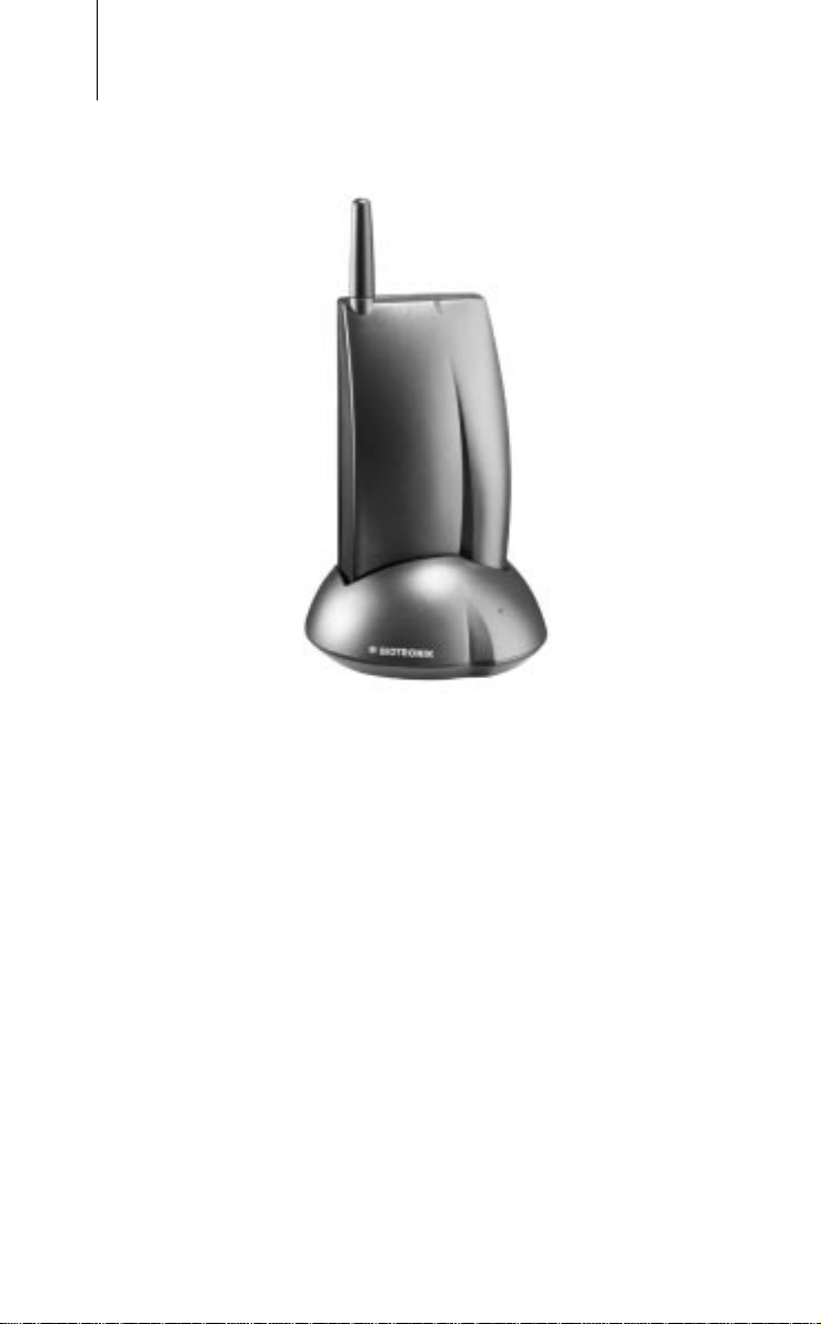
Patient device
with components
The patient device (Fig.1) is developed for home use
and consists of a mobile unit and the r espective charging station. The patient can also carry the mobile unit
with them in their normal daily activi ties .
The patient device rechargeable batteries that make
an operating time of about 24 h possible. The patient
device receives messages from the implant and for-
Page 4
3
Home Monitoring - Introduction
Fig.1
Patient Device with
Charging Station
RUC 200
wards them to a
BIOTRONIK Service Center via
mobile communications.
Cardio Report
The service cent er c ompiles the mes sages int o a comprehensive report (Cardio Report). This Cardio Report
is tailored to the individual needs of the patient and is
sent to the attending physician via fax.
• For further information about the patient device, please refer to the respective Users Manual.
• The standard functions are described in the Actros
family technci a l m a nu a .
• The additional Home Monitoring functions of the
BA03 DDDR are found in this manual
+
Page 5

Indications and Contraindications
Indications and Contraindications
4
For the general indications and contraindications
please refer to the Actros
Basically, the indications and contraindications of the
BA03 DDDR are identical to that for the rate adaptive
dual chamber pacemaker Actros DR
teria for the Home Monitoring Function are described
as follows:
+
Family tech nical manu al.
Criteria for using Home Monitoring
There are no contraindications for use of the Home
Monitoring function. This function has no influence on
the diagnostic or therapeutic functionality of the pacemaker. The patient must be capable and willing to
manage certain tasks associated with Home Monitoring. Usage of the Home Monitoring system i s inappropriate in the following cases:
• The patient can not handle the system as intended,
because of their physical or psychological condition.
• There is no GSM cellular service available in the local area of the patient’s home.
• The patient often stays (i.e. works) in areas where it is not permitted to use mobile phones.
+
. The special cri-
Note: Home Monitoring does not replace the regular fol-
low-up examination.
When using the Home Monitoring function, the time
interval between the follow-ups must not be prolonged.
Caution:
The da ta tran smitte d by Ho me Mo n itoring are not
suitable for diagnosis, because not all information
avail able i n the implant is being transmitte d .
Page 6

5
Transmission of Message
Transmission of Message
The Home Monitoring function can be switched ON or
OFF with the programming device. If the Home Monitoring function is active, the transmission of the
implant data can be triggered as follows:
• Periodic message at predefined time intervals
• Message activated by the patient
The attending physician himself decides if the patient
should trigger a transmission by programming this
paramater ON or OFF. The patient activated message
does not effect the programmed periodic message.
Note: Please note that with the BA03 DDDR, the Home Mon-
itoring f u nc tio n is only poss ibl e in fol l ow ing pacing
modes: DDD, DDDR, DDI, DDIR.
Periodic Message
The time and interval (Monitoring Interval) of the periodic message are programmable. For the periodic
message, a time between 0:00 and 24:00 can be set.
Generally, it is recommended to select a time between
0:00 and 4:00. For every Monitoring Interval, a data
string is generated in the implant and the transmissi on
is act ivate d.
Patient Activated Message
Application of a magnet over the implant activates a
transmission. The attending physician should inform
the patient in detail about the handling and the physical
symptoms that suggest a magnet applicatio n by the
patien t.
Caution:
The magnet effect must be programmed "synchronous" if the attending physician enables the patient to
transmit messages.
Page 7

Diagnostic Memory Functions
Diagnostic Memory Functions
6
BA03 DDDR has the same standard functions as the
Actros DR
unavailable. Contrary to the Actros DR
DDDR has the ability to use all memory functions
simultanously.
When the Home Monitoring function is activated, the
following diagnostic memory functions are recorded
automatically and transmitted by the Home Monitoring
System:
Event Counter
The fun ction Event Counter can record the following events:
• As percentage
• Vs percentage
Event sequences:
• As - Vs percentage
•As - Vp percentage
• Ap - Vs percentage
• Ap - Vp percentage
+
, with the except i on that the Gain Monito r is
+
, the BA03
With every perio di c message, the counte r is reset.
Page 8

7
Diagnostic Memory Functions
Arrhythmia
VES Classifications
The VES events are classified according to their complexity. The following classifications are available:
1. Number of Single-VES Event sequence A-V-VES-A...
2. Number of VES Coupl ets: Event sequence A-V-VES-VES-A.
3. Number of VES Tr iplets : Event sequence A-V-VES-VES-VES-A.
4. Number of VES Run s
Sequence of 4...8 consecutive VES.
Event sequence A-V-VES-VES-...-A.
5. Maximum number of VES /h
6. Number of Ventri cular T achyc ardias: VT with dura ti on > 8 VES and
Activity Chart
This function records data, that are characteristic for
the activities of patient and pacemaker system:
• Mean value of actual ventricular heart rate
• Maximum value of actual ventricular heart rate
• Activity duration at maximum sensor rate
120 bpm
≥
Page 9

Functio ns of Ho me Mo nitoring
Functions of Home Monitoring
Programmable Parameters
The functions of Home Monitoring and their
parameters can be set with the programmers EPR
plus
1000
ing software SWM 1000/B-KT0.0 is ne cessar y
The functions of Home Monitoring are availa b le onl y in following pacing modes: DDD, DDDR, DDI, DDIR.
When using the Home Monitoring system, the transmission interval must be selected. This monitoring
interval can be from one to 30 d ays. If the stan dard setting is selected , data w ill be trans mitted daily. For the
periodic message, a time between 0:00 and 24:00 is
programmed. It is recommended that a time between
0:00 and 4:00 is selected, as pr eset in the standard program.
and TMS 1000
plus
8
. Therefore, the correspond-
The patient activated message can also be programmed ON or OFF. This option is deactivated in the
standard progra m
Page 10

Technical Data
Modes
Valid when Home Monitoring function is activated:
DDD, DDDR, DDI, DDIR
Valid when Home Monitoring function is deactivated:
DDD, DDDR, DDI, DDIR, DVI, DVIR, VDD, VDDR , DOO,
DOOR, VVI, VV IR, AAI, AAIR, VOO, VOOR , AOO, AOOR,
DDI/T, DDI/TR, DDT, DDTR, DVT, DVTR, VDT, VDTR,
VVT, VVTR, AAT, AATR, VDI, OFF
Home Monitoring parameters
Technical Data
9
Home Monitoring
Monitoring
interval
Time of
transmission
Patient activated
data trans mission
Off, On
1...(1) ...30 days
0:00...23:50 h:min
Off, On
Page 11

Technical Data
10
Pulse and Timing Data
Basi c rate
Hysteresis
Repetitive Hyster.
Scan Hysteres i s
Upper rate (UTR)
Night Rate
Tachycardia mode
Rate l i mitat i o n
Dynamic AV delay
AV delay values
AV safety interval
Ventricular
Blanking time
Magnet effect
Pulse amplitude A
2)3)
1)
2)
30 ... (1) ... 88 ... (2) ... 122 ... (3) ... 140 ... (5) ... 180 ppm
2)
Off; -5 ... (5) ... -50 bpm
Off; 1 ... (1) ... 10
Off; 1 ... (1) ... 10
2)
100; 110; 120; 130; 140; 160; 185 ppm Off; (and basic rate se ttings) 2:1; WKB (automatic setting) 190 ... 220 ppm low; medium; high; ind ividual; fixed 15; 50; 75; 100; 120 ... (10) ... 200; 225; 250; 300 ms
(programma b l e in 5 ran g es )
100 ms
12; 16; 24; 32; 40; 48; 56; 72 ms Auto; asynchronous; synchronous 0,1 ... (0,1) ... 4,8 ... (1,2) ... 8,4 V
0,1 ... (0,1) ... 4,8 ... (1,2) ... 8,4 V
V
Pulse width A
Sensitivity A
Refractory period A
1) 37°C, 500 Ω
2) The respective intervals result from the rate f in the formula t = 60.000 / f (t in ms, f in ppm)
3) In the case of an electronic failure
0,1; 0 ,2; 0,3 ; 0 ,4; 0,5 ; 0, 75 ; 1 , 0; 1 ,5 m s 0,1; 0 ,2; 0,3 ; 0 ,4; 0,5 ; 0, 75 ; 1 , 0; 1 ,5 m s
V
0,1 ... (0,1) ... 1,5 ... (0,5) ... 7,5 mV 0,5 ... (0,5) ... 7,5 mV
V
200 ... (25) ... 775 mV 250; 300; 350; 400 ms
V
Page 12

Technical Data
11
ARP extension
Automatic mode
conversion
Lead polarity
Pace A/V
Sense A/V
Rate Adaption
Sensor gain
Autom. s. gain
Sensor threshold
Rate increase
Max.
Sensor rate
Rate decrease
0 ... (50) ... 350 ms
Off; On (in the modes DDD(R) and VDD(R))
unipolar; bipolar / unipolar; bipolar unipolar; bipolar / unipolar; bipolar
1 ... 40 ( in 32 step s ) Off; O n very low; low; medium; high; very high 1; 2; 4; 8 ppm/s
1)
80 ... (5) ... 180 ppm/s 0,1; 0,2; 0,4; 0,8 ppm/s
1) In the modes DDIR-, DVIR-, VVIR-and VOOR, lower maximum sensor rates result than indicated here (partly depending on the selected AV interval). The respective values are displayed
by the programmer.
Page 13

Parameter a t Replacement Indication
Technical Data
12
Basic rate
programmed value decrea sed b y 11%
(in the modes DVI(R), DDI(R), DVT(R), DDI/T(R),
decreases by 4,5–11%, depend ing on the programmed
AV delay)
Magnet rate
Pulse genera tor b ehavior aft er reach ing ERI
Magnet Mode Cycles 1-10 after
magnet application
Automatic Asynch. at 80 ppm Synch. with basic rate reduced by 4.5 -
Asynchronous Asynch. at 80 ppm Asynch. with basic rate reduced by 4.5
Synchronous Synch. with basic rate reduced by 4.5
Pulse amplitudes
sensitivity
Home Monitoring
after ERI
Default
- 11%
progr amme d valu es
progr amme d valu es
0 ...(1)...14 days 14 days
After Cycle 11
11%
- 11%
Synch. with basic rate reduced by 4.5 -
11%
Page 14

Technical Data
Features
• Home Monitoring
Additio n al functions con form with A ct ros DR
• Automatic sensor gain
• Extensive VES analysis
• External pulse control up to 800 ppm
• Dual chamber IEGM with event marker
• 24 hour trend with pacing part in %
• Sensor test trend with rate forecast
• Automatic mode conversion
• High definition threshold test in the range of 0,1 up to 4,8 V with 0,1 V resolution
•P/R wave test
13
• Retrograde conduction test
• Reaction to vasovagal syncopes
•Night program
• Heart rate histogram
• Sensor rate histogram
• Assisted follow-up
• Activi ty ch art
• Event counter
• Patient data memory
• Analog telemetry
• Temporary program activation
• Controlled impulse amplitude s
Page 15

Default Programs
Technical Data
14
Parameter/Function
Home Monitoring
Mode
Autom. m. conversion
Basic rate
Hysteresis
Repetitive hystere s.
Scan hysteresis
Night program
Upper rate ( UTR )
Dynamic AV delay
Ventric. blanking time
Magnet effect
Pulse amplitude A
Pulse width A
Factory- Standard- Safe Settings Program Program
Off Off Off
DDD DDDR VVI
Off Off —
60 ppm 60 ppm 7 0 ppm
Off Off Off
——Off
——Off
Off Off Off
160 ppm 160 p pm —
medium medium —
24 ms 24 ms —
Auto Auto Auto
3,6 V 3, 6 V —
3,6 V 3,6 V 4,8 V
V
0,4 ms 0,4 ms — 0,4 ms 0,4 ms 1,0 ms
V
Sensitivity A
Refractory tim e A
ARP
1,5 mV 1,5 mV — 2,5 mV 2,5 mV 2,5 mV
V
425 ms 425 ms — 250 ms 250 ms 300 ms
V
0 ms 0 ms —
Page 16

Technical Data
15
Parameter/Function
Sensor threshold
Sensor gain
Auto. Sensor gain.
Rate increase
Max. sensor rate
Rate decrease
Lead
polarity
Pace A/V
Sense A/V
Statistics
Factory Standard- Save Settings Program Program
—medium—
—6 —
—Off—
—2 ppm/s—
—120 ppm—
—0,4 ppm/s—
unipolar unipolar unipolar
unipolar unipolar unipolar
standard standard standard
Page 17

Materials in Contact to Human Tissue
Housing Titanium
Grommet Silicone
Connector
Receptacle Epoxy resin
Coating (for unipolar Silicone (if used)
devices)
Programmer
EPR 1000
plus
, and TMS 1000
plus
Technical Data
16
Electrical Data
Circuit
Input impedance A
Pulse form
Polarity
Current dr ain
BOS, i nhibit ed
BOS, 100 % stimul.
Conducting surface
Conducting shape
1) 37°C, 500 Ω
1)
Hybrid electronics wi th VLSI-CMOS-Chip
270 k
Ω
330 k
V
Ω
bipha si c, as ymme tr i c
cathod ic
12 µA 24 µA
2
36 cm
flattened ellipsoid a l
Page 18

Battery
Technical Data
17
Power Source
Manufacturer
Type
Voltage
Voltage at ERI
Nominal Capacity
Nominal service
time
Expected service
time
Remaining capacity
at ERI in Ah
Mechanical Data
Lead connection
Li/J
Wilson Greatbat ch
WG 8431
2,8 V
2,5 V
1)
1,3 Ah
Service Times
6,7 years
2)
at pulse ampl itudes 3,6 V
5,1 year s
3)
at pulse ampl itudes 3,6 V
0,13
IS-1 (accepts unipolar and bipolar)
Mass
Volume
Dimensions
X-Ray
Identification
1) Data from battery manufacturer
2) Calculated with formula: T= 2740 x C
3) Expected service time based on all avialable data as provided from the battery manufacturer
30 g
3
13 cm
6 x 45 x 57 mm
EE
/(I
bat
BOS
+ I
)
EOS
Page 19

Technical Data
18
Tolerances of Factory Settings
Basic rate
Interference rate
Basic interval
Escape interval
Magnet rate
Magnet Interval
AV delay
Basic rate
≤
70 ppm
70-90 ppm
91-110 ppm
111-130 ppm
≥130 ppm
Pulse amplitude
Peak value
EN 50 06 1 mean
1)
Data according to EN 50 061
60 ± 1 min-1 1000 ± 3 ms 1000 ± 5 ms 90 ± 1 min-1 (for 10 cycles) 664 ± 2 ms (for 10 cy cles )
180 +3/-1 ms 180 +3/-1 ms 160 +15/ -5 ms 140 +15/ -5 ms 120 +15/ -5 ms 100 +15/ -5 ms
Atrium Ventricle
3,6 +0,25 V/ -0,45 V 3,6 +0,25 V/ -0,45 V 3,3 +0,25 V / -0,45 V 3,3 +0,25 V / -0,45 V
Pulse width
Sensitivity
15 ms sin
40 ms sin
EN 50061 Triangle
Refractory period
Run-away protection
1) 37°C, 500 Ω
0,43 ±0,02 ms 0,43 ±0,02 ms
2
1,5 ±0, 5 mV
2
2,5 ±0,5 mV
1,8 ±0, 5 mV 2,5 ±0,5 m V
425 +5 / -2 0 m s 250 +5 / -20 ms
210 ±20 min
-1
210 ±20 min
-1
Page 20

Order Information
Technical Data
19
Model
BA03 DDDR
uncoated
Lead Connection Ord er Numb er
IS-1 122 126
Federal Co mmunication s Commission Disclosure
The BA03 DDDR pacemaker is equipped with an RF transmitter for
wirele s s communic ati o n s. This tra nsm i tte r is authorized by rule unde r
the Medical Im pla nt Co m mun ication s S ervic e (47 CFR Par t 95) and
must not cause harmful interference to stations operating in the
400.150 - 406.000 MHz band in the Meteorological Aids (i.e., transmitters and receivers used to communicate we ath e r data), th e Meteorological Satellite, o r the Earth Exploration Sate l l ite Services and must
accept interference that may be caused by such aids, including interference that may cause undesired operation. This transmitter shall be
used only in acco rda nce wit h the F C C Rul es gov erning the Medical
Implant Co mmunications Service. Analog and digi tal voice communi cations are prohibited. Although this transmitter has been approved by
the Federal Com mu ni cati ons C o mmis sion , there is no guarante e that it
will not receive interference or that any particula r tr an smission from
this transmitter will be free from interference.
The FCC ID number for this device is: PG6BA0T.
 Loading...