

Page 1

T
l'O!
|
O
VENTILATOR
TESTERS
Models
OPERATOR'S
VT-1B & VT-2
MANUAL
BIO-TEK
INSTRUMENTS,
INC.
Page 2

Page 3
BIO-TEK®
INSTRUMENTS,
INC.
MODELS
VT-1B & VT-2
OPERATOR’S
MANUAL
PART
REVISION
VENTILATOR
MANUAL
NUMBER
8801015
A
TESTERS
BIO-TEK
HIGHLAND
WINOOSKI,
802-655-4040
800-451-5172
800-242-4685
TELEX
FAX
0-1
INSTRUMENTS,
PARK,
VT
(SERVICE)
94-0136
802-655-7941
BIO
BOX
998
05404-0998
TEK
SHVT
INC.
USA
Page 4

DOCUMENT
REVISION
RECORD
Revision,
A
date,
3/4/1996
and
section
Table
2.3-1
Table
2.3-2
Section
Section
Section
Section
2.5
2.5-1
2.5-3
2.6
Changes
Power
Input:
Changed
“100/115/230/240
Deleted
Changed
specification
Added
on
Item
“The
electronic
Revised
Deleted
Revised
Table
printer”
Power
timing
Note:
pressure,
1,
Printer,
printer
unit.”
Figure
second
Figures
2.6-1:
with
Output.
measurement
from
“Infant
volume
second
rests
on
2.5-1,
paragraph.
2.5.2-1
Replaced
“Citizen
“100/115/230
VAC.”
“t
.01%”
respiration
and
flow
sentence:
the
top
and
references
IDP
3110
accuracy
to
“+
2.5% + 1
rates
settings.”
Changed
of
the
tester’s
2.5.3-1.
to
“Seiko
printer.”
VAC”
are
dependen
to
LSD.”
to
read
DPU
”
Section
Section
Section
Section
Note:
3.1
3.3
4.1
5
Above
Part
Number
changes
8801015.
were
made
to
Part
Item
7:
Revised
Item
24.c.,
seconds”
“standard
printer.”
Deleted
Deleted
Table
paragraphs
plugged
Number
to
second
second
5-1,
into
8801000
printer
first
sentence:
“less
than
Seiko
DPU-40
sentence.
paragraph.
PRINTER:
with
“Check
the
correct
20
Replaced
and
released
operating
Changed
seconds”;
printer”
to
see
line
instructions.
to
second
if
the
power.”
on
“about
20
changed
“Citizen
and
th
printer
is
|
~
Bio-Tek®
is a registered
0-2
trademark
of
Bio-Tek
Instruments,
Inc.
Page 5
TABLE
OF
CONTENTS
DOCUMENT
TABLE
LIST
LIST
INTRODUCTION
UNPACKING
2
2.1
2.2
2.3
2.4
2.4.1
2.4.2
2.5
2.5.1
2.5.1.1
OF
OF
FIGURES
OF
TABLES
MODELS
Summary
Applications
Model
Model
Adult
Infant
Model
Ventilator
REVISION
CONTENTS
AND
INSPECTION
VT-1B & VT-2
of
Features
VT-1B
VT-1B
Lung:
Lung:
VT-1B
Tester
Definitions
RECORD
or
VT-2
Adult
Location
Location
or
VT-2
Front
of
Keys
DESCRIPTION
and
Potential
Specification
Lung
and
and
Description
and
Description
Electronics
Panels
Model
Unit
Users
VT-2
of
of
Adult/Infant
Components
Components
Lungs
2.5.2
2.5.3
2.6
2.7
INSTALLATION
3
3.1
3.2
3.3
3.4
3.6.1
3.6.2
3.6.3
3.6.4
3.6.5
RE
Ventilator
Ventilator
Accessories
Optional
Preparation
Operating
Set-Up
Setting
Applications
Connecting
Ventilator
Status
Full
Auto
Trend
Assist
Accessories
of
Up
Test
Test
Repeat
Test
Test
Tester
Tester
Precautions
User-Programmable
the
the
Tests
AND
for
Use
Models
Ventilator
Rear
Side
Panels
OPERATION
VT-1B
Panel
0-3
Parameters
and
to
the
VT-2
Model
for
VT-1B
Computer
or
VT-2
Control
Lung
A
A
Page 6
TABLE
OF
CONTENTS
(CONTINUED)
3.6.5.1
3.6.6
3.6.6.1
3.6.6.2
3.6.6.3
3.6.6.4
3.6.7
3.6.7.1
3.6.7.2
3.6.7.3
3.6.7.4
3.6.8
3.6.8.1
3.6.8.2
4
SAFETY,
4.1
4.2
4.3
Assist
Leak
Lung
Patient
Patient
Test
and
Leak
with
Compliance
Test
Tubing
Tubing
Ventilator + Patienc
Waveform
Volume
Airway
Lung
Air
External
External
External
Monitor
Waveform
Pressure
Pressure
Flow
Tests
Pressure
Flow
Waveform
MAINTENANCE,
Electrical
Safety
Cleaning
Storage
and
Shipping
Adult
Tests
Leak
Test
Compliance
Tubing
Tests
Monitor
Waveform
Wavcforı
Moni'or
Test
Test
Lung
Test
Compliance
Monitor
Monitor
STORAGE
&
SHIPPING
Test
Π
^
+
>
ra
一
da
>>>
In
>
Ον
>
O
>
00
と
と
OO
5
6
APPENDIX
Ad
A.2
A.3
A.3.1
A.3.1.1
A.3.1.2
А.3.1.3
A.3.1.4
TROUBLESHOOTING
REFERENCES
A
Ventilator
ANSI
Lung
Classification
Inspiratory
Change
Testing
Standards
Ventilators:
from
Expiratory
Change
from
Standards
for
Ventilators
Background
Phase
Inspiration
Phase
Expiration
to
to
0-4
Expiration
Inspiration
Page 7
Page
TABLE
OF
CONTENTS
(CONTINUED)
A-H
A-17
A-17
A-19
A-19
A-20
A-21
B-1
B-1
A.3.2
A4
A
4.1
А.4.1.1
A.4.1.2
А.4.1.3
Α.4.2
APPENDIX
B.1
Principles
Theory
Algorithms
Time
Pressure
Volumes,
Hardware
B
Airway
of
Dynamic
of
Operation
Readings
Readings
Flows,
and
Software
Restrictors
Leak,
Ventilator
and
Testing
Compliance
0-5
Page 8
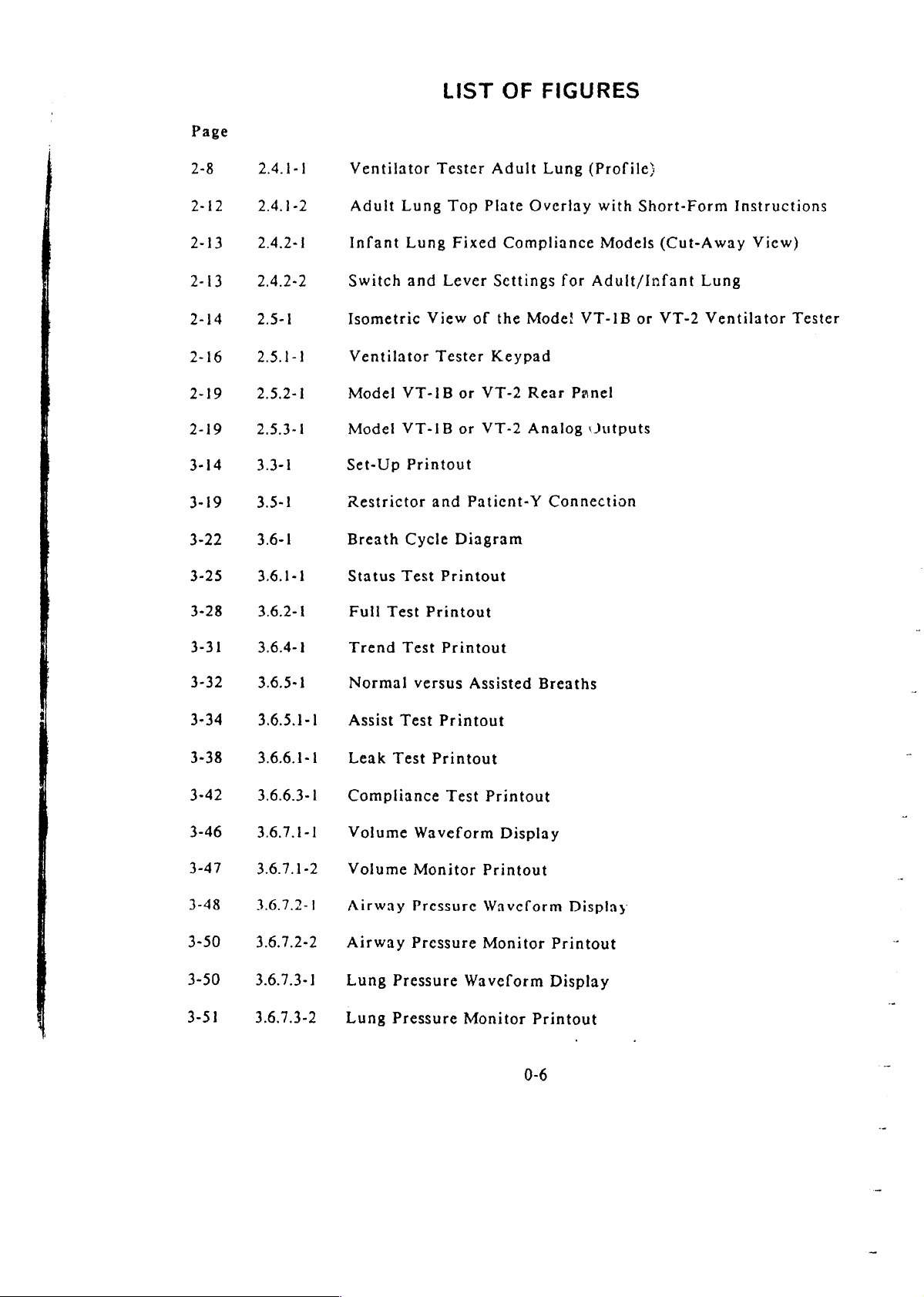
LIST
OF
FIGURES
2-8
2-12
2-13
2-13
2-14
2-16
2-19
2-19
3-14
3-19
3-22
3-25
3-28
2.4.1-1
2.4.1-2
2.4,2-1
2.4.2-2
2.5-1
2.5.1-1
2.5.2-1
2.5.3-1
3.3-1
3.5-1
3.6-1
3.6.1-1
3.6.2-1
Ventilator
Adult
Infant
Switch
Isometric
Ventilator
Model
Model
Set-Up
Restrictor
Breath
Status
Full
Lung
Lung
and
VT-1B
VT-1B
Printout
Cycle
Test
Test
Tester
Top
Fixed
Lever
View
Printout
of
Tester
or
or
and
Paticnt-Y
Diagram
Printout
VT-2
VT-2
Adult
Plate
Overlay
Compliance
Settings
the
Mode!
Keypad
Rear
Analog
Lung
(Profile}
with
Models
for
Adult/Infant
VT-1B
Panel
Jutputs
Connection
Short-Form
(Cut-Away
or
VT-2
Instructions
View)
Lung
Ventilator
Tester
3-31
3-32
3-34
3-38
3-42
3-46
3-47
3-48
3-50
3-50
3-51
3.6.7.3-1
3.6.7.3-2
3.6.4-1
3.6.5-1
3.6.5.1-1
3.6.6.1-1
3.6.6.3-1
3.6.7.1-1
3.6.7.1-2
3.6.7.2-1
3.6.7.2-2
Trend
Normal
Assist
Leak
Compliance
Volume
Volume
Airway
Airway
Lung
Lung
Test
versus
Test
Test
Waveform
Monitor
Pressure
Pressure
Pressure
Pressure
Printout
Assisted
Printout
Printout
Test
Printout
Printout
Waveform
Monitor
Waveform
Monitor
Breaths
Display
Display
Printout
Display
Printout
0-6
Page 9
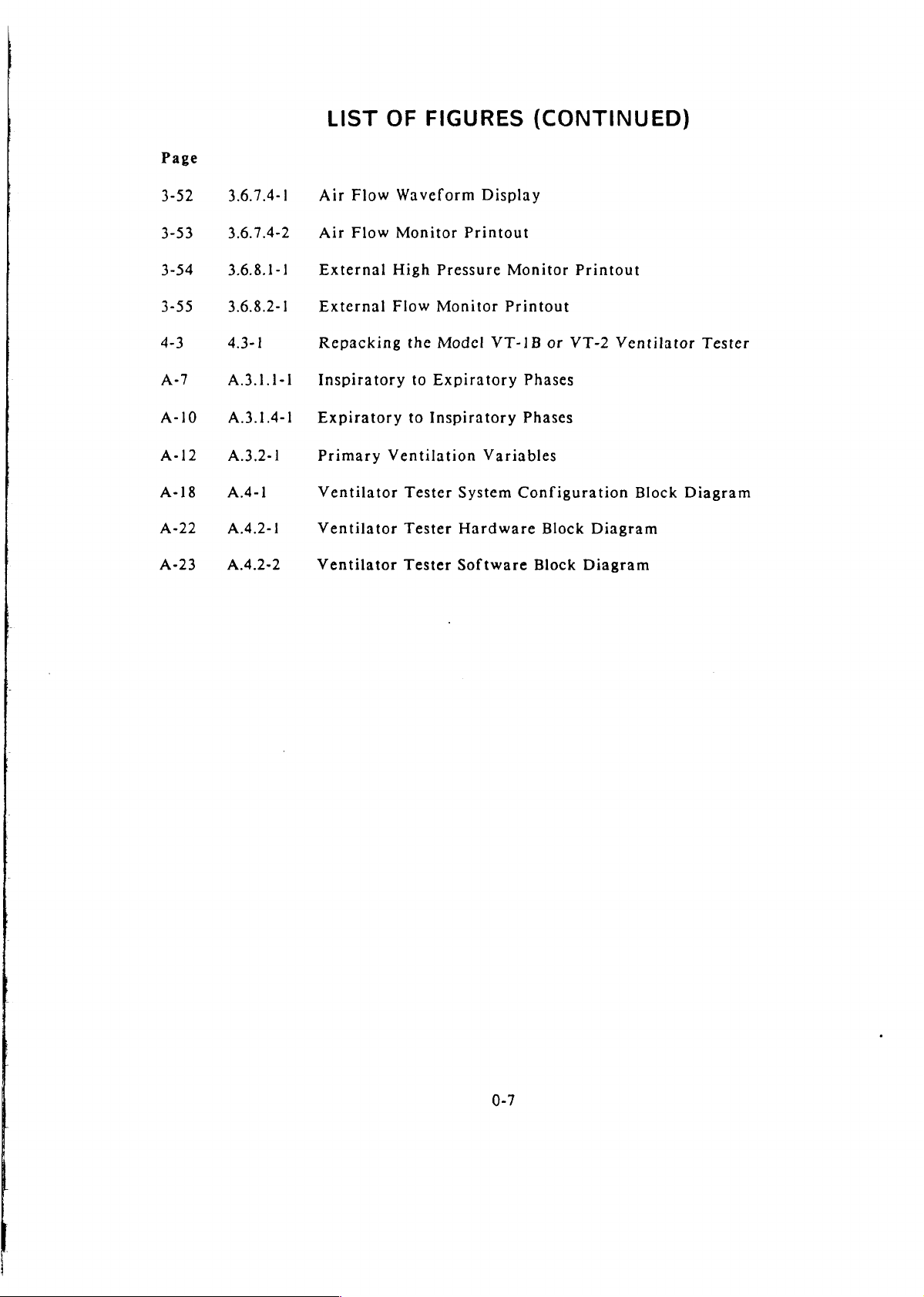
Page
3-52
3.6.7.4-1
LIST
Air
Flow
OF
FIGURES
Waveform
(CONTINUED)
Display
3-53
3-54
3-55
4-3
A-10
A-12
A-18
A-22
A-23
3.6.7.4-2
3.6.8.1-1
3.6.8.2-1
4.3-1
A.3.1.1-1
A.3.1.4-1
A.3.2-1
A.4-1
A.4.2-1
A.4.2-2
Air
Flow
External
External
Repacking
Inspiratory
Expiratory
Primary
Ventilator
Ventilator
Ventilator
Monitor
High
Flow
the
to
to
Ventilation
Tester
Tester
Tester
Printout
Pressure
Monitor
Model
Expiratory
Inspiratory
System
Hardware
Software
Monitor
Printout
VT-1B
Variables
or
Phases
Phases
Configuration
Block
Block
Printout
VT-2
Diagram
Diagram
Ventilator
Block
Tester
Diagram
0-7
Page 10
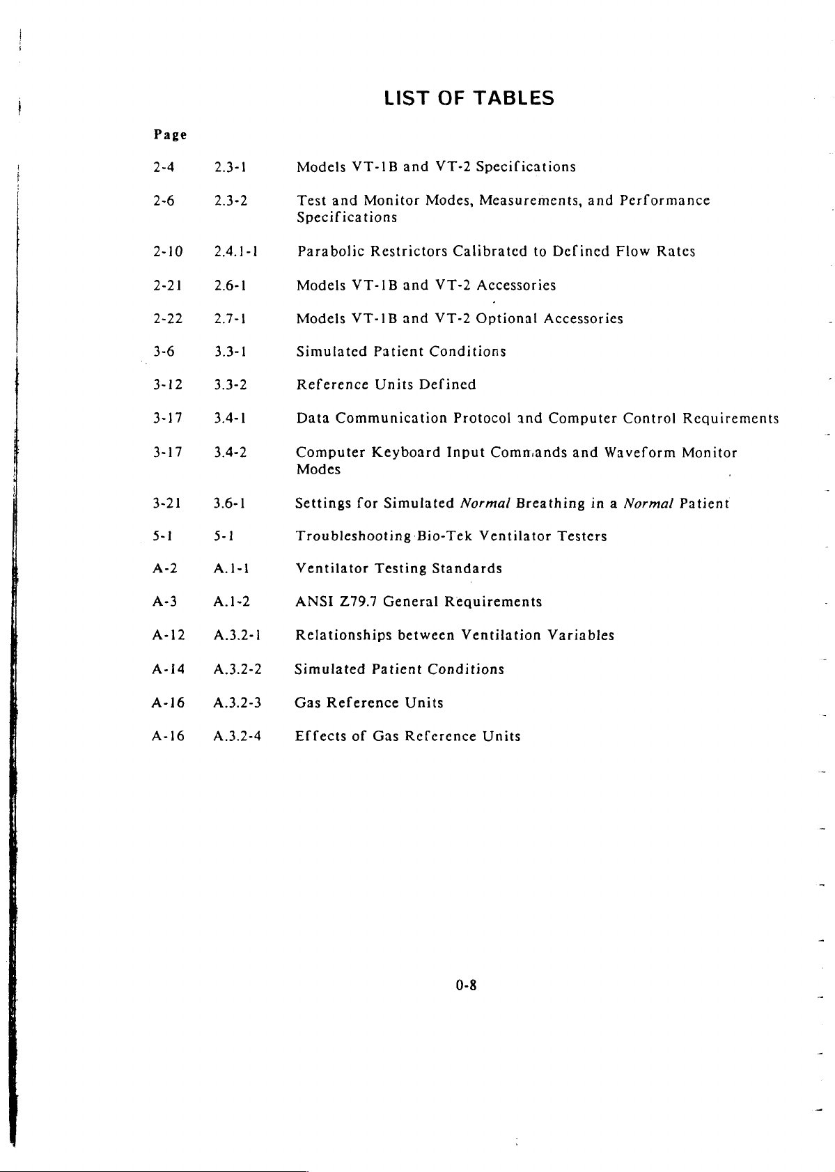
Page
LIST
OF
TABLES
2-4
2-6
2-10
2-21
2-22
3-6
3-21
5-1
A-2
2.3-1
2.3-2
2.4.1-1
2.6-1
2.7-1
3.3-1
3.3-2
3.4-1
3.4-2
3.6-1
5-1
А.1-1
Models
Test
Specifications
Parabolic
Models
Models
Simulated
Reference
Data
Computer
Modes
Settings
Troubleshooting
Ventilator
VT-1B
and
Monitor
Restrictors
VT-1B
VT-1B
Patient
Units
Communication
Keyboard
for
Simulated
Testing
and
VT-2
Modes,
and
VT-2
and
VT-2
Conditions
Defined
Bio-Tek
Standards
Specifications
Measurements,
Calibrated
Accessories
Optional
Protocol
Input
Commands
Normal
Ventilator
to
Defined
Accessories
and
Computer
and
Breathing
Testers
and
Performance
Flow
Control
Waveform
in a Normal
Rates
Requirements
Monitor
Patient
A-3
A-12
A-14
A-16
A-16
А.1-2
A.3.2-1
A.3.2-2
A.3.2-3
A.3.2-4
ANSI
Relationships
Simulated
Gas
Effects
Z79.7
Patient
Reference
of
Gas
General
between
Units
Reference
Requirements
Ventilation
Conditions
Units
0-8
Variables
Page 11
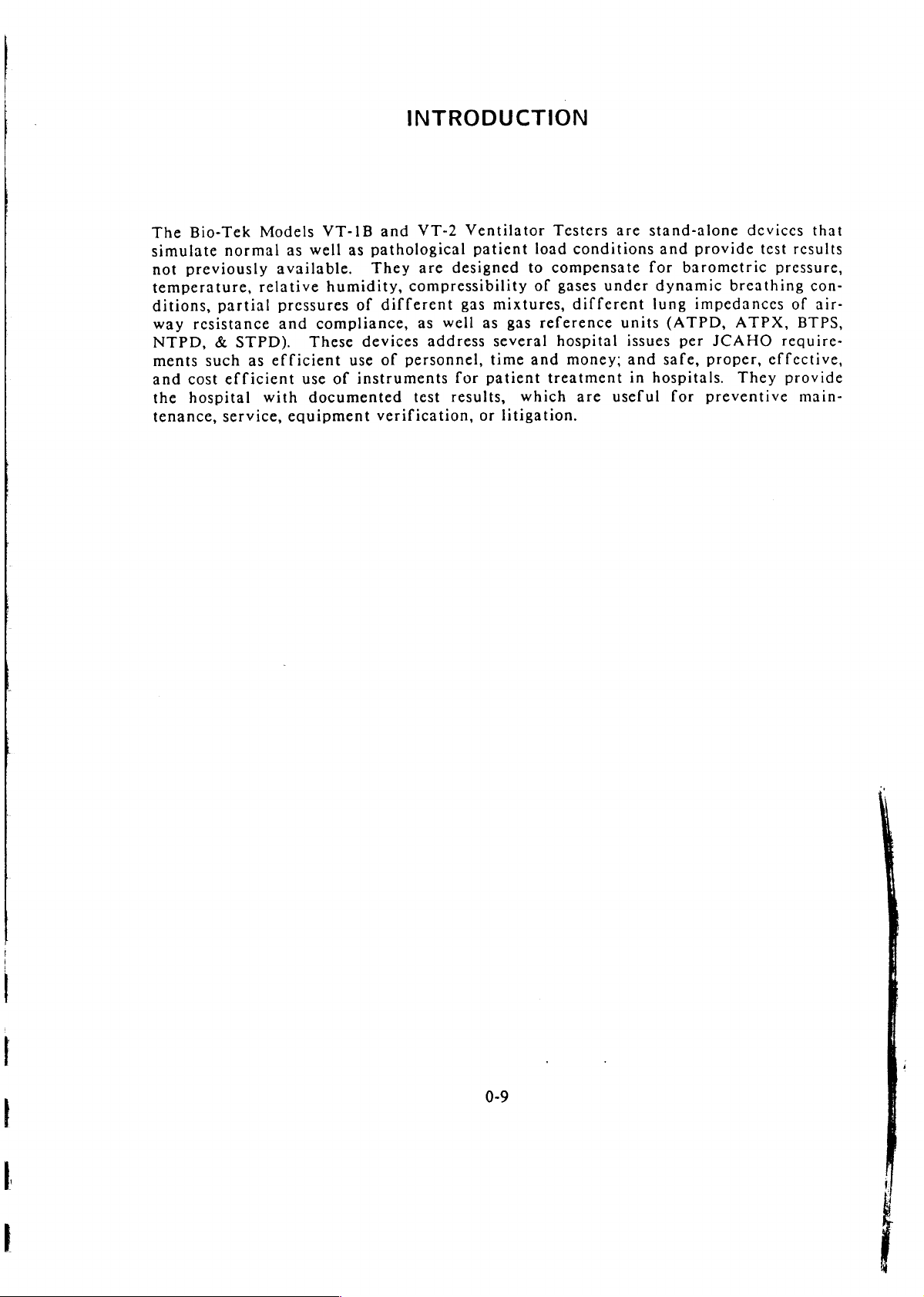
The
Bio-Tek
simulate
not
temperature,
ditions,
way
NTPD,
ments
and
the
tenance,
normal
previously
partial
resistance
&
such
cost
efficient
hospital
service,
Models
relative
STPD).
as
efficient
with
VT-1B
as
well
available.
humidity,
pressures
and
compliance,
These
use
of
documented
equipment
INTRODUCTION
and
as
pathological
They
compressibility
of
different
devices
use
of
personnel,
instruments
verification,
VT-2
are
as
well
address
test
Ventilator
patient
designed
gas
mixtures,
as
several
time
for
patient
results,
or
litigation.
to
gas
which
Testers
load
conditions
compensate
of
gases
different
reference
hospital
and
money;
treatment
are
are
under
units
issues
and
in
useful
stand-alone
and
provide
for
barometric
dynamic
lung
impedances
(ATPD,
per
JCAHO
safe,
proper,
hospitals.
for
preventive
devices
test
pressure,
breathing
ATPX,
require-
effective,
They
provide
that
results
con-
of
air-
BTPS,
main-
0-9
Page 12

Page 13
1.1
To
Unpacking
prevent
I.
2.
3.
4.
5.
1
and
Inspection
damage
Lay
name
Open
Use
If
you
rying
Inspect
physical
instructions,
Department
the
plate
the
both
do
case
to
carrying
face-up
snap
hands
not
top
the
Model
damage
UNPACKING
the
ventilator
case
and
locks
of
to
lift
anticipate
and
bottom
VT-1B
and/or
call
the
Bio-Tek
at:
1-800-24-BIOTK.
AND
tester,
on a vibration-free
the
the
carrying
the
instrument
repacking
in
or
missing
handle
the
VT-2
Customer
always
pointed
case
out
the
shipping
lung,
items.
unit
To
INSPECTION
unpack
and
of
box.
electronics
report
Service
it
in
work
toward
the
within a short
remove
carrying
damage
at
surface
you.
the
unit,
1-800-451-5172
the
top.
following
with
case
bottom.
time,
store
and
accessories
and
receive
manner:
the
or
Bio-Tck
the
car-
for
further
Service
6.
To
report
ice,
Biomedical
missing
Department.
items,
call
Bio-Tek
Instruments
and
ask
for
Customer
Serv-
1-1
Page 14

Page 15
2
MODELS
VT-1B
&
VT-2
DESCRIPTION
Bio-Tek
Model
the
Other
and
following
2.1
VT-2
Model
than
VT-2
1.
2.
3.
4.
5.
6.
7.
Summary
manufactures
Adult/Infant
VT-1B
that,
differ
additional
Enhanced
Trend
External
External
Auto-Zero,
Computer
Carrying
Test,
of
Features
by
the
from
Pressure
Flow,
Pressure,
Control
Case
and
sells
Ventilator
having
two
units
the
Bio-Tek’s
features:
Accuracy,
provided
with
and
the
an
infant
are
identical
wheels.
Potential
Model
Tester.
previous
by a bi-directional
lung
Users
VT-IB
The
assembly
in
design
models
Adult
latter
and
model
with
operation.
because
RS232,
Ventilator
differs
2
infant
they
and
Tester
physically
lung
compliances.
The
Model
incorporate
and
VT-1B
the
from
the
I.
The
Models
simple
2.
The
tests
3.
Fourteen
compensate
ATPX,
the
4.
The
as
5.
Volume,
recorder
6. A printer
7.
A
collection
to
user
and
BTPS,
unit.
display
well
as
bi-directional
VT-IB
operate.
interface
enters
parameters
data
flow,
via
is
and
data
for
differences
NTPD,
allows
in
and
the
tester’s
provided
specialized
and
VT-2
is a keyboard
by
responding
can
be
STPD)
the
user
tabular
RS232
form.
pressure
analog
for
hard
interface
performance
ventilators
of
measured
between
and
to
observe
waveforms
output
copy
2-1
are
pressure-sensitive
to
prompts
in
reference
actual
volume,
jacks.
of
test
provides
analyses.
on
automated
unit
test
conditions
flow,
may
also
results
computer
cost-effective,
pads;
an
LCD
test
conditions
and
be
and
other
the
display.
modes;
by
preprogramming
pressure
recorded
data.
control
portable
user
initiates
the
user
(ATPD,
waveforms
on a chart
for
and
can
ATPS,
data
Page 16
The
following
*
Dedicated
*
Provides
*
Test
results
*
Corrects
*
Choice
*
Volume,
*
Volume,
*
Status/quick
*
Full
Test/Auto-Repeat
*
General
*
Printer
*
Complies
The
Bio-Tek
adultand
28
in
for
of
6
reference
flow,
flow,
flow
port
with
ventilator
list
highlights
infant
measurements
2-to-4
atmospheric
2
airway
test
and
with
ANSI,
breath
pressure
to
check
pressure
printer,
ISO,
testers
the
ventilator
through
cycles
and
units
for
waveform
pressure
ventilator
for
15
measurements
RS232
ASTM
features
13
gas
conditions
volumes
displays
analog
controls
measurements
computer
standards
can
be
used
of
the
tester
test
modes
&
flows
outputs
control
by
Models
the
following
VT-1B
*
Trending
*
Tests
*
Tests
*
*
Microprocessor
*
6-linc
*
Menu
*
Self
*
*
*
Upgradcable
*
Carrying
with
with
Leak
&
LCD
driven
test/diagnostic
Easy
calibration
Auto-zero
organizations
and
VT-2
of
Tidal
lung
any
gas
compliance
based
graphic
and
for
transducer
design
case
with
testers:
Volume
impedance
mixture
tests
display
user
friendly
software
check
whecls.
and
agencies:
drift
l.
2.
3.
4.
5.
6.
7.
8.
9.
2.2
Applications
Ventilators
performance
Laboratory
better
than
available,
according
Federal
regulatory
Organizations
Respiratory
Hospital
Equipment
quality
Colleges
Training
Preventive
Ventilator
are
studies
the
there
to
clinical
biomedical
control,
and
organizations
maintenance
dealers and
used
be
clinically
indicate
older
was
criteria.
agencies
evaluation
for
therapists
manufacturers,
production
professional
and
and
manufacturers’
as
life-support
acceptable,
that
models;
no
however,
convenient
pulmonary
clinical
sales
and
schools
and
service
devices;
new
generation
medical
of
engineers
and
design,
without
until
method
devices
physiologists
technicians
and
marketing,
service
departments
organizations
representatives.
therefore,
potential
of
ventilators
the
Bio-Tek
to
evaluate
inspection
it
is
important
risks
perform
Ventilator
ventilator
and
calibration,
that
to
the
substantially
Testers
performance
their
patients.
were
The
Models
of:
neonatal,
ventilators.
VT-IB
and
pediatric,
Additional
VT-2
ventilator
adult
critical
applications
are
testers
care,
listed
home
as
are
dedicated
the
care,
anesthesia,
following
to
test
the
performance
and
items 1 through
transport
19,
Page 17
bacteria
filters
lt.
pressure
gauges/meters
breathing
calibration
compressors
CPAP/PEEP
demand
flow
flow
9.
10.
These
available
ventilation
IPPB
patient
testers
1.
The
2.
The
ensure proper
actual
about
on
circuit
syringes
valves
meters
regulators
machines
breathing
are
also
a
ventilator’s
patients,
tester
tester
patient
can
could
valves
devices
circuits
capable
for
example:
help
diagnose
be
operation
conditions.
of
providing
performance,
ventilator
used
by
during
long-term
12.
13.
14.
15.
16.
17.
18.
19.
valuable
as
failure
ventilator
pressure
pressure
pulmonary
equipment
resuscitators
respirometers
spirometers
ventilators
wall
air/gas
information
well
as
the
at
the
manufacturers
treatment
regulators
relief
of
valves
function
outlets
effects
patient’s
and
patients
test
not
previously
of
artificial
bedside.
physicians
by
simulating
to
The
synchronometer
instability
The
their
Studies
perfusion
percentage
respiratory
of
The
determine
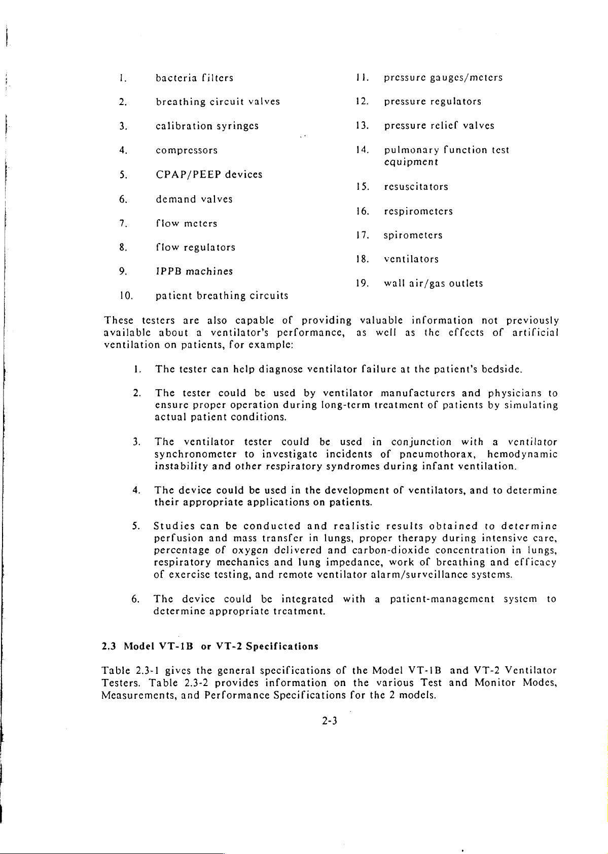
2.3
Model
Table
Testers.
Measurements,
2.3-1
Table
ventilator
device
appropriate
exercise
device
VT-1B
gives
2.3-2
and
and
other
could
can
be
and
mass
of
oxygen
mechanics
testing,
could
appropriate
or
VT-2
the
general
provides
Performance
tester
to
be
applications
conducted
Specifications
could
investigate
respiratory
used
in
transfer
delivered
and
lung
and
remote
be
integrated
trcatment.
specifications
information
Specifications
be
used
incidents
syndromes
the
development
on
patients.
and
realistic
in
lungs,
and
impedance,
ventilator
of
on
2-3
in
conjunction
of
pneumothorax,
during
of
results
proper
carbon-dioxide
with
the
the
for
therapy
work
alarm/surveillance
a
patient-management
Model
various
the 2 models.
infant
ventilators,
of
VT-IB
Test
ventilation.
obtained
during
concentration
breathing
and
and
with
hemodynamic
and
to
intensive
systems.
VT-2
Monitor
a
ventilator
to
determine
determine
in
and
efficacy
system
Ventilator
care,
lungs,
to
Modes,
Page 18
The
following
*
Dedicated
*
Provides
*
Test
results
*
Corrects
*
Choice
*
Volume,
*
Volume,
*
Status/quick
*
Full
Test/Auto-Repcat
*
General
*
Printer
*
Complies
The
Bio-Tek
1.
2.
3.
4.
list
highlights
adult
28
for
of 6 reference
flow, 2 pressure
flow,
flow
port
with
Federal
Organizations
Respiratory
Hospital
and
measurements
in
2-to-4
atmospheric
airway
test
to
check
and
pressure
with
printer,
ANSI,
ventilator
regulatory
biomedical
the
infant
breath
ISO,
testers
therapists
ventilator
through
cycles
and
units
for
waveform
pressure
ventilator
for
15
measurements
RS232
ASTM
agencies
for
evaluation
features
gas
conditions
volumes & flows
analog
measurements
computer
standards
can
be
and
and
clinical
of
tester
13
test
displays
outputs
controls
used
of
medical
pulmonary
the
Modcis
modes
control * Upgradcable
by
the
following
physiologists
engineers
VT-1B
*
Trending
.*
Tests
*
Tests
*
*
Microprocessor
*
6-linc
*
Menu
*
Self
*
*
*
Carrying
devices
and
with
with
Leak & compliance
LCD
driven
test/diagnostic
Easy
calibration
Auto-zero
organizations
technicians
and
of
case
VT-2
Tidal
lung
any
graphic
and
for
transducer
design
with
testers:
Volume
impedance
gas
mixture
tests
based
display
user
friendly
software
check
whecls.
and agencics:
drift
5.
6.
7.
8.
9.
2.2
Applications
Ventilators
performance
Laboratory
better
available,
according
The
of:
ventilators.
than
Models
neonatal,
Equipment
quality
Colleges
Training
Preventive
Ventilator
studies
there
to
control,
are
used
be
clinically
the
older
was
clinical
VT-1B
pediatric,
Additional
manufacturers,
production
and
professional
organizations
maintenance
dealers
as
indicate
criteria.
and
and
life-support
that
models;
no
convenient
VT-2
adult
applications
sales
and
schools
and
service
manufacturers’
devices;
acceptable,
new
however,
ventilator
critical
are
and
design,
organizations
without
generation
until
method
testers
care,
listed
as
marketing,
service
representatives.
therefore,
potential
of
ventilators
the
Bio-Tek
to
evaluate
are
dedicated
home
the
care,
following
inspection
departments
it
and
is
important
risks
Ventilator
ventilator
to
anesthesia,
items | through
to
perform
test
the
calibration,
that
their
the
patients.
substantially
Testers
performance
performance
and
were
transport
19.
2-2
Page 19

Table
2.3-1.
Models
VT-IB
and
VT-2
Specifications
Analog
Compliances
Outputs
(C)
(L/cmH,O)
(per
ANSI)
Awy
Resistor
(cmH,O/L/min)
(per
ANSI)
Set-Up
(R,)
Choices
Volume
Fiow
Airway
ADULT
.05
02
01
NOTE:
(or
altitude
Pressure
(VT-IB/VT-2)
(C50)
(020)
(C10)
Infant
717
to
777
in
the
specification
ADULT
(VT-IB/VT-2)
50
20
5
NOTE:
All
resistors
Time:
Date:
Equipment
ID:
Atmospheric
Relative
Room/Gas
Pressure
Reference
Humidity:
Temp.:
Units:
Units:
1
1
À
compliances
mmHg).
two
models,
from
Bio-Tek.
INFANT
are
Pres.:
Volt = I
Volt = 50
Volt = 20
INFANT
.003
(C3)
001
(CI)
are
within
Although
customers
500
200
parabolic
12-hour
Entry
Up
to
600
0
to
15
to
cmH,O
Pressure;
for
others.)
ATPX, ATPD,
or
NTPD,
measurements,
liter
(Adult
only)
LPM
(Adult
only)
cmH O (Adult 4 Infant)
(VT-2)
ANSI
specifications
readings
may
and
accuracies
obtain
higher
altitude
(VT-2
types.
format,
in
Month/Day/Year
16
numeral
to
800
mmHg
AM
or
digits
PM
format
100%
50°C
or
psi for
(cmH,O,
ATPS,
for
all
External
mmHg,
volume
High
or
BTPS,
and
from
are
not
infant
kPa
STPD,
flow
sea
level
affected
lungs
to
885
above
per
feet
this
ANSI
Auto-Zero
Audible
Pressure
Over-
Alarm
Every
time a TEST
every
10
minutes
lung
pressure
pressure.
Over
125
cmH, O in
or
MONITOR
if
still
in
any
transducers.
Infant
Manual
or
2-44
one
Adult
key
is
mode,
ZERO
lungs.
selected
for
for
and/or
airway
external
and
Page 20
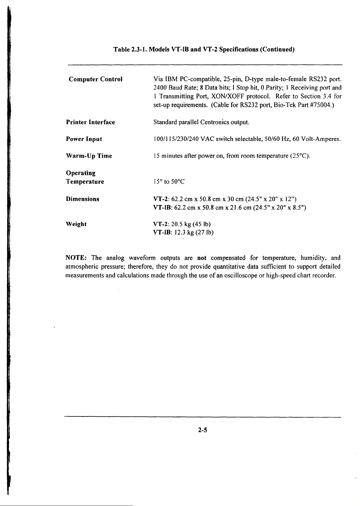
Computer
Table
Control
2.3-1.
Models
VT-IB
Via
IBM
PC-compatible,
2400
Baud
Rate; 8 Data
1
Transmitting
set-up
requirements.
and
Port,
VT-2
Specifications
25-pin,
bits; I Stop
XON/XOFF
(Cable
for
(Continued)
D-type
protocol.
RS232
male-to-female
bit, 0 Parity; | Receiving
Refer
to
port,
Bio-Tek
RS232
Section
Part
#75004.)
port.
port
3.4
and
for
Printer
Power
Warm-Up
Operating
Temperature
Dimensions
Weight
NOTE:
atmospheric
measurements
Interface
Input
Time
The
pressure;
analog
and
waveform
therefore,
calculations
Standard
100/115/230/240
15
15°
VT-2:
VT-IB:
VT-2:
VT-IB:
outputs
they
made
parallel
minutes
to
50°C
62.2
62.2
20.5
12.3
do
not
through
after
cm x 50.8
kg
are
Centronics
VAC
power
cm x 50.8
(45
Ib)
kg
(27
Ib)
not
compensated
provide
the
use
of
output.
switch
on,
cm x 30
cm x 21.6
quantitative
an
selectable,
from
room
cm
(24.5" x 20" x 12")
cm
data
oscilloscope
50/60
Hz,
60
temperature
(24.5" x 20" x 8.5")
for
temperature,
sufficient
or
high-speed
(25°C).
to
support
chart
Volt-Amperes.
humidity,
recorder.
and
detailed
Page 21

Table
MEASUREMENTS
I:E
RATIO
INSP.
EXP.
EXP.
CYCLE
RESPIRATION
TIME
TIME
INSP.
HOLD
HOLD
TIME
PRESSURE
2.3-2.
βατε]φίοφιο
Test
and
Monitor
[TEST
Oi<i
atras
<|
-lelolulololsizlilxix
0100
o
5
uo
0/0
ee
oje
oje
oje
MODESÍ
Jel
<|
MONITOR
出
WAVEFORMS
<
wii
zl
i|
Modes,
(gis)
<|
Measurements,
MODES | RANGE/UNITS
lu
[SE
Lio
al
lolrir
1:99 & 39:1
O
TO
O
TO
ο
ΤΟ
ο
TO
O
TO
O
TO 75
and
60
60
15
99
120
Performance
SECS
SECS
SECS
SECS
SECS
BPM
ACCURACY
+
2.5% + 1
Specifications
|
RESOLN
(DISPLAY)
LSD
0.1
PEAK/MAX
MIN
MEAN
INSTANT
PEAK/MAX
MIN
INSTANT
ASSIST
EXTERNAL
COMPL
VOLUME
ADULT
INFANT
x
TV
INSTANTANEOUS
BASELINE,
MİNUTE VOLUME
FLOW
INSP
EXP
INSTANT
LEAK
EXT
DEFAULT:
(MANAS
Note:
AWY
AWY
PRES,EEP
AWY
PRESSURE
AWY
LUNG
LUNG
PRESSURE
LUNG
PRES
HIGH
LANCE
TIDAL
TIDAL
VARIATION
PEEP
FLOW
FLOW
FLOW
RATE
GAS
FLOW
C=.05
KANUNGÜ)
Infant
PRES
PRES
PRES
PRES
PRES
VOLUME | @|
VOL
VOL
VOL
oje
61006
ee
o
oje
ο
@/@
1@/@/@
©
eee
ee
oje
ο
(AIR,
O2.N,0.CO, & (02)
L/emH20:
respiration
ATM
rates
PR=760
are
e
0
ο
ο o
e
ο
e
ο
©
© 0.05
o
0
©
o
ο
©
ο
-15
0
@ | 0
O
0.005
3
TV
TV
0
10
mmHg:
Rh=S0X;
dependent
on
pressure,
TEMP»
TO
125
cmH20f
TO 7 psi(cm,0)
TO
250
ml/cmH,O
TO
2.2
LITERS | £33
TO
0.3
LITERS | +42
TO
993
OF TV
RANGE
RANGE
TO
199
LITERS
O
TO
250
LPM
TO
75
LPM
NTPO
25*C;
volume
AIR | +51
MV:BTPS;
and
flow
21%f.s. ょ LSD
#21f.s.
TV
TV
TV & FLOW:ATPX:
settings.
ει
5Ό
+
21
RDG
RDG + 4LSD | 0.001
RDG + 4LSD | 0.001
ACCURACY
ACCURACY
RDG ¢ 4LSD
0.1
l
0.001
0.001
ο.οι
1
0.1
l
PRES:cmH20
2-6
Page 22
2.4
Model
The
Models
under
infant
human
explanation
physiologic
ventilators.
adult
VT-1B
of
Adult
VT-IB
and
and
load
These
pediatric
how a ventilator
Lung
and
VT-2
conditions;
lungs
lungs.
have
closely
interfaces
Model
built-in
the
Model
Refer
VT-2
Adult/Infant
adult
VT-2
approximate
to
Section
with
Bio-Tek’s
lung
also
the
A.3:
Lungs
models
has
physiological
to
built-in
Theory
ventilator
test
adult
infant
characteristics
of
Operation,
testers.
ventilators
lungs
to
for
test
of
an
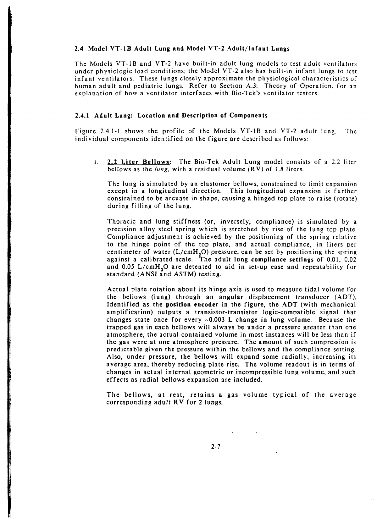
2.4.1
Figure
individual
Adult
2.4.1-1
1.
Lung:
components
2.2
bellows
The
except
constrained
during
Thoracic
precision
Compliance
to
the
centimeter
against a calibrated
and
standard
Actual
the
Identified
amplification)
changes
trapped
atmosphere,
the
predictable
Also,
average
changes
effects
Location
shows
Liter
lung
0.05
bellows
gas
under
the
identified
Bellows:
as
the
lung,
is
simulated
in a longitudinal
to
filling
hinge
plate
state
gas
were
area,
in
as
of
and
alloy
adjustment
point
of
water
L/cmH,O
(ANSI
rotation
(lung)
as
the
once
in
each
the
at
given
pressure,
thereby
actual
radial
profile
be
arcuate
the
lung
steel
and
position
outputs
actual
one
the
internal
bellows
and
Description
of
the
on
the
The
Bio-Tek
with a residual
by
an
elastomer
direction.
in
shape,
lung.
stiffness
spring
of
(L/cmH,O)
scale.
are
detented
ASTM)
about
through
for
every
bellows
contained
atmosphere
pressure
the
reducing
(or,
which
is
achieved
the
top
The
testing.
its
an
encoder
a
transistor-transistor
~0.003 L change
will
within
bellows
geometric
expansion
of
Components
Models
figure
inversely,
plate,
pressure,
adult
to
hinge
angular
always
volume
pressure.
will
plate
VT-1B
are
described
Adult
volume
bellows,
This
causing a hinged
is
stretched
by
the
and
can
lung
aid
in
axis
in
the
be
in
the
bellows
expand
rise.
or
incompressible
are
included.
and
VT-2
as
follows:
Lung
is
figure,
The
The
model
(RV)
of
constrained
longitudinal
compliance)
by
positioning
actual
be
set
compliance
set-up
used
displacement
logic-compatible
in
under a pressure
most
instances
amount
some
volume
consists
1.8
liters.
top
rise of
of
compliance,
by
positioning
ease
and
to
measure
the
ADT
lung
volume.
of
and
the
radially,
readout
lung
adult
to
limit
expansion
plate
to
is
simulated
the
lung
the
spring
settings
repeatability
tidal
transducer
(with
greater
will
be
such
compression
compliance
is
volume,
lung.
of a 2.2
expansion
is
further
raise
(rotate)
by
top
plate.
relative
in
liters
the
spring
of
0.01,
volume
(ADT).
mechanical
signal
Because
than
less
than
setting.
increasing
in
terms
and
such
The
liter
a
per
0.02
for
for
that
the
one
if
is
its
of
The
bellows,
corresponding
at
adult
rest,
RV
for 2 lungs.
retains
2-7
a
gas
volume
typical
of
the
average
Page 23
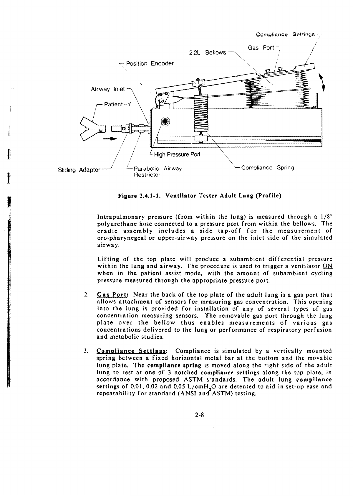
Airway
Patient-Y
—
ο
Inlet
Position
Encoder
©
2.2L
Bellows
X
Compliance
Gas
x
、
Port
7
Settings
/
/
一
7
|
|
Sliding
Adapter
Intrapulmonary
polyurethane
cradle
oro-pharynegeal
airway.
Lifting
within
when
pressure
2.
Gas
allows
into
concentration
plate
concentrations
and
—
Port:
the
metabolic
/
/
parabolic
L
Restrictor
Figure
the
in
attachment
over
2.4.1-1.
hose
assembly
of
the
lung
the
patient
measured
Near
lung
the
studies.
is
measuring
delivered
High
Airway
pressure
connected
includes
or
upper-airway
top
plate
and
airway.
through
the
back
of
sensors
provided
bellow
Pressure
Ventilator
(from
to a pressure
will
The
assist
mode,
the
of
the
for
for
sensors.
thus
to
the
Port
—
Compliance
Tester
within
a
side
pressure
produce a subambient
procedure
appropriate
top
measuring
installation
enables
lung
Adult
the
tap-off
with
plate
‘he
removable
or
performance
Lung
lung)
port
from
for the
on
the
is
used
the
amount
pressure
of
the
adult
gas
concentration.
of
any
measurements
Spring
(Profile)
is
measured
within
inlet
side
differential
to
trigger a ventilator
of
port.
lung
of
several
gas
port
of
respiratory
through
the
measurement
of
subambient
is a gas
through
of
bellows.
the
simulated
pressure
port
This
opening
types
the
various
perfusion
a
1/8"
The
of
ON
cycling
that
of
gas
lung
gas
3.
Compliance
spring
lung
lung
accordance
settings
repeatability
Settings:
between a fixed
plate.
to
rest
of
The
at
with
0.01,
for
compliance
one
proposed
0.02
standard
Compliance
horizontal
spring
of 3 notched
ASTM
and
0.05
L/cmH,0
(ANSI
metal
is
moved
compliance
s:andards.
and
ASTM)
2-8
is
simulated
bar
are
at
the
along
settings
The
detented
testing.
by a vertically
bottom
the
along
adult
to
right
aid
and
side
the
lung
in
set-up
mounted
the
movable
of
the
adult
top
plate,
compliance
ease
in
and
Page 24
Compliance
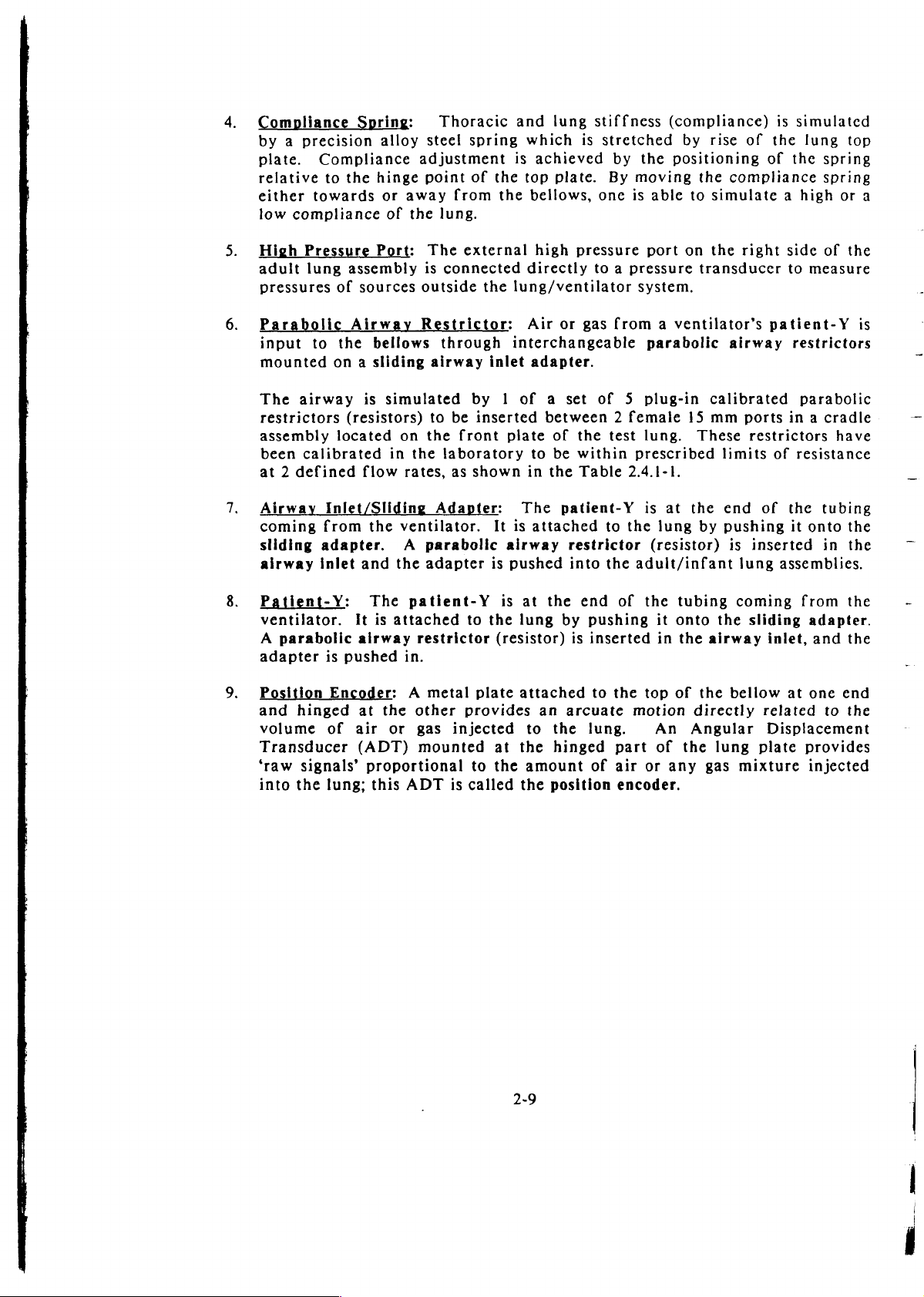
4.
by a precision
plate.
relative
either
low
compliance
5.
High
adult
pressures
Spring:
Compliance
to
the
towards
Pressure
lung
assembly
of
sources
alloy
hinge
or
of
Port:
Thoracic
steel
adjustment
point
away
the
lung.
The
is
connected
outside
from
external
and
spring
of
which
is
the
top
the
bellows,
directly
the
lung/ventilator
lung
is
achieved
plate.
high
pressure
stiffness
stretched
by
By
one
to a pressure
(compliance)
the
positioning
moving
is
able
port
system.
by
rise
of
of
the
compliance
to
simulate a high
on the
right
transducer
is
simulated
the
lung
the
side
to
measure
top
spring
spring
or
a
of
the
Parabolic
input
mounted
The
restrictors
assembly
been
at 2 defined
Airway
coming
sliding
airway
Patient-Y:
ventilator.
A
adapter
Position
and
volume
Transducer
‘raw
into
to
the
on a sliding
airway
located
calibrated
Inlet/Sliding
from
adapter.
inlet
parabolic
is
En
hinged
of
signals’
the
lung;
Airway
bellows
is
(resistors)
flow
the
and
The
It
airway
pushed
at
air
(ADT)
proportional
this
Restrictor:
simulated
on
in
the
rates,
ventilator.
A
the
patient-Y
is
attached
restrictor
in.
er: A metal
the
other
or
gas
mounted
ADT
through
airway
to
the
Adapter:
parabolic
adapter
inlet
by 1 of a set
be
inserted
front
laboratory
as
shown
is
to
the
plate
provides
injected
to
is
called
Air
or
gas
interchangeable
adapter.
between 2 female
plate
of
the
to
be
within
in
the
Table
The
patient-Y
It is
attached
airway
pushed
is
lung
(resistor)
attached
at
the
the
the
at
the
by
an
to
the
hinged
amount
position
restrictor
into
end
is
arcuate
from a ventilator’s
parabolic
of 5 plug-in
15
test
lung.
prescribed
2.4.1-1.
to
the
the
adult/infant
of
pushing
inserted
to
the
motion
lung.
part
of
air
encoder.
is
the
top
or
These
at
the
lung
by
(resistor)
tubing
it
onto
in
the
airway
of
the
directly
An
Angular
of
the
any
gas
patient-Y
airway
calibrated
mm
ports
restrictors
limits
end
pushing
the
lung
of
of
is
inserted
lung
assemblies.
coming
sliding
inlet,
bellow
related
Displacement
plate
mixture
is
restrictors
parabolic
in a cradle
have
resistance
the
tubing
it
onto
the
in
the
from
at
the
adapter.
and
the
one
end
to
the
provides
injected
=.
2-9
—
πο.
WE
Page 25
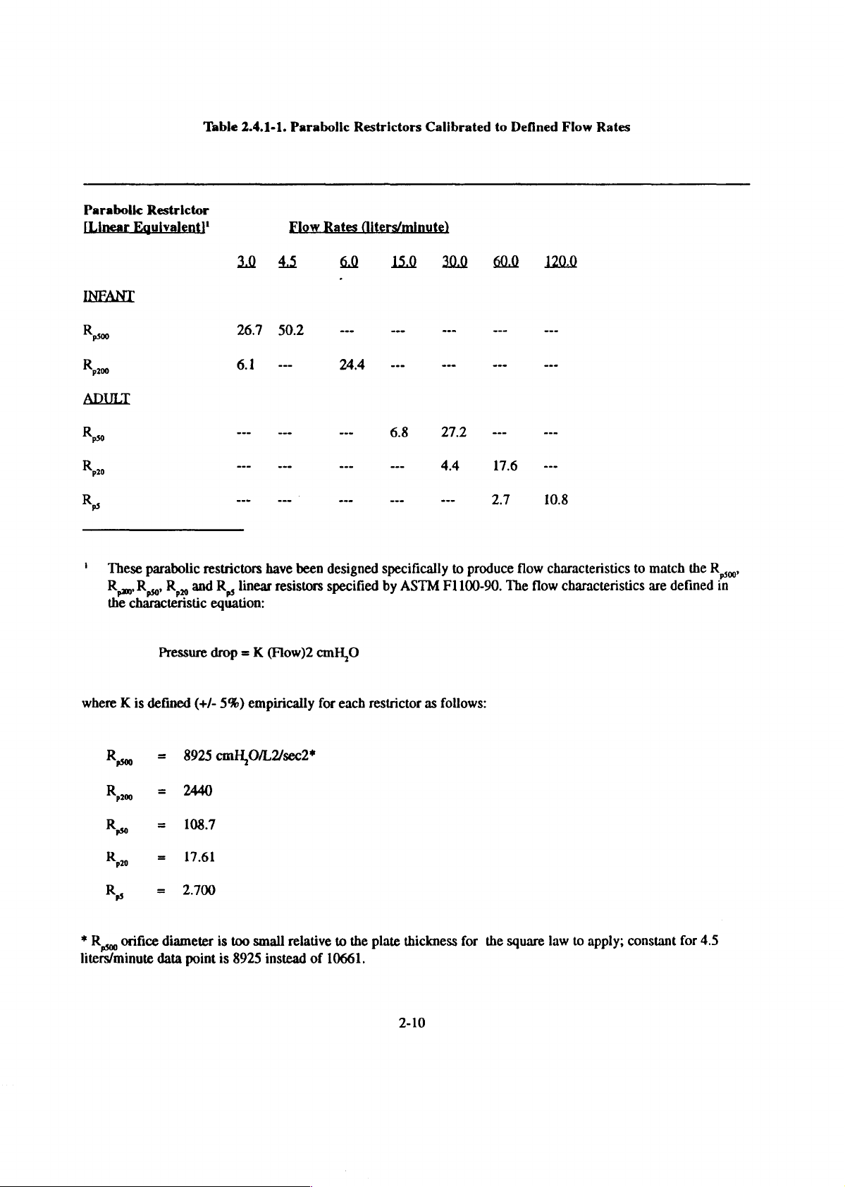
Table
2.4.1-1.
Parabolic
Restrictors
Calibrated
to
Defined
Flow
Rates
Parabolic
[Linear
R
R
R
R
'
These
R,
ro R so
the
characteristic
Restrictor
Eguivalent)'
parabolic
Ryn.
and
restrictors
R,,
equation:
Flow
26.7
50.2
61
---
ーー ーー
—
ue
have
linear
resistors
Rates
(liters/minute)
ーー
24.4
ーー
ーー
---
ーー
oo
been
designed
specified
specifically
by
ASTM
---
---
4.4
---
---
176
27.
to
produce
F1100-90.
---
---
---
108
flow
characteristics
The
flow
characteristics
to
match
are
the
R,
defined
in
Pressure
where K is
*
Rso
liters/minute
К»
К»
Ro
R
в,
orifice
defined
=
=
=
=
=
diameter
data
drop = K
(+/-
5%)
8925
cmH,
2440
1087
1761
2.700
is
too
point
is
8925
(Flow)2
empirically
cmH,O
for
each
O/L2sec2*
small
relative
instead
of
10661.
to
restrictor
the
plate
2-10
as
follows:
thickness
for
the
square
law
to
apply;
constant
for
45
Page 26
The
position
uncompensated
calculated.
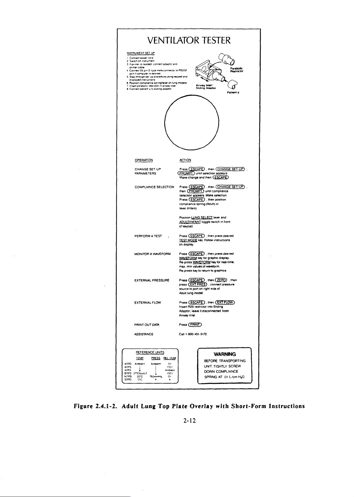
11.
Short-Form
that
user-programmable
Section
2.4.1-2.
provides
encoder
Instructions
3:
Installation
translates
measurement
Overlay:
a
handy
parameters
and
angular
of
the
gas
On
summary
and
for
Operation).
displacement
in
the
the
top
of
instructions
performing
This
overlay
lung
plate
of
the
from
of
ventilator
is
which
the
lung
for
reproduced
bellows
is
an
setting
tests
into
volume
overlay
(refer
as
Figure
an
is
up
to
2.4.2
By
mounting
ventilator
Figure
that
and
the
this
ANSI
Figure
adult
lung.
Infant
mounting
2.4.2-1
are
used
nconatal
keypad
portion
and
2.4.2-2
and
1.
2.
Lung:
the
electronics
testers
to
(0.001
and
is
ASTM
infant
ADULT/INFANT
whether
transducer
ADULT/INFANT
the
toggle
and
that
Location
the
infant
can
is a cut-away
obtain
display
not
shown
standards.
shows
lung
the
switch
air
and
Description
)
lung
assembly
assembly
be
packaged
view
the 2 compliances
L/cmH,0)
must
in
the
and
adult
is
used
from
be
the
switch
between
Toggle
lung
for
Lung
to
ensure
the
lungs.
removed
figure.
settings
measurement.
ventilator
of
on
the
over
the
infant
in
the
same
of
the
infant
required
Note
that
to
expose
These
that
the 2 compliance
Switch:
pressure
Select
that
Lever:
the
desired
is
directed
Components
same
carrying
fixed
enable
transducer
lung,
lung
to
the
The
This
base
showing
simulate
portion
the
lungs
the
settings
toggle
lever
lung
to
plate
the
case.
infant
are
user
or
is
is
it.
as
the
overall
designed
switch
the
used
chosen
size
the 2 internal
infant
of
available
the
lung
to
choose
position
infant
in
in
(0.003
tester
compartment
conjunction
adult
of
to
confirm
on
lung
the
the
between
Model
lung,
L/cm
that
the
determines
and
Bio-Tek
canisters
H,0)
houses
and
with
the
infant
pressure
with
VT-2
3.
Infant
compliance
0.003
canisters
and
Compliance
of
the
0.001.
as
shown
lung
These
in
Selector
must
compliance
Figure
Lever:
also
be
2.4.2-1.
When
selected.
values
the
are
infant
The
user
determined
lung
can
by
is
selected
choose
the
between
size
of
the
the
Page 27
INSTAUMENT
6
7
8
Connect
Switch
1
printer
ane
printer
Connect
a
port
Step
w
displayed
Position
Insert
Connect
power
on
instrument
13
needed
cable
25-pin D type
computer
through
instructions
comphance
parabolic
patient y to
SET-UP
set-up
OPERATION
CHANGE
PARAMETEAS
COMPLIANCE
PERFORM A TEST
MONITOR A WAVEFORM
EXTERNAL
EXTERNAL
PRINT
OUT
ASSISTANCE
VENTILATOR
cord
connect
adaptor
and
mais
connector
to
is
desired
procedure
spring/lever
restrictor
in
shamg
SET-UP
SELECTION
PRESSURE
FLOW
DATA
using
away
adaptor
on
・
R$232
keypad
and
lung
modes
inlet
ACTION
Press
(PROMPT ) unul
Make
then
selection
Press
compliance
lever
Position
ADULTINFANT
of
keypad
Press
TEST
on
display.
Press
WAVEFORM
Re-press
max,
Re-press
Press
press
source
Adult
Press
Insert
Adaptor;
Airway
Press
Сай
3-800-451-5172.
(ESCAPE) . then
change
(Infant)
WING
(ESCAPE ) ,
MODE
min
to
lung
(ESCAPE).
A20
intet
TESTER
Airway
inlet/
Sliding
Adaptor
selaction
and
then
until
appears.
Make
„then
spring
(Adult)
SELECT
toggle
then
key.
Follow
,
than
key
for
graphic
WAVEFORM
values
of
waveform.
key
to
return
.
men
port
on
right
model.
then
restrictor
into
leave
it
disconnected
(CHANGE
appears
compliance
selection
position
or
lever
and
switch
in
press
instructions
press
display.
key
for
real-time,
to
graphics.
CZERO) . then
:
connect
pressure
side
of
Sliding
from
Parabolic
Restrictor
Pationt-y
SET-UP)
front
desired
desired
.
Figure
2.4.1-2.
ATPD
Arpx
BTPS
37"Clbody)
NTPD
STPO
Adult
REFERENCE
TEMP
Ambient
| |
20°C
xe
Lung
UNITS
PRESS
Ambient
760mmHg
REL
Ambient
Top
HUM
OF
1008
1008
о,
+
Plate
Overlay
2-12
WARNING
BEFORE
UNIT,
TIGHTLY
DOWN
COMPLIANCE
SPRING
with
TRANSPORTING
SCREW
AT
01
Lem
НЮ
Short-Form
Instructions
Page 28
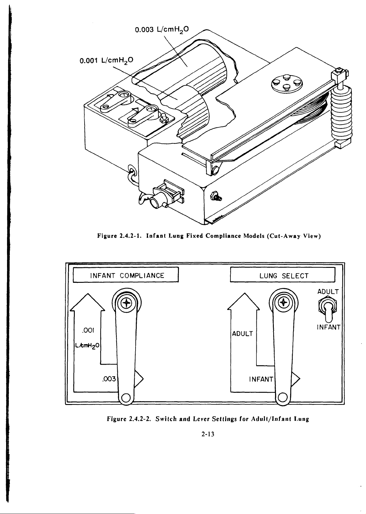
0.003
L/cmH,0
INFANT
001
LAmH20
Figure
003
2.4.2-1.
COMPLIANCE
>
©
Infant
Lung
Fixed
Compliance
ADULT
Models
LUNG
INFANT
(Cut-Away
SELECT
>
O
View)
ADULT
INFANT
Figure
2.4.2-2.
Switch
and
Lever
2-13
Settings
for
Adult/Infant
Lung
Page 29
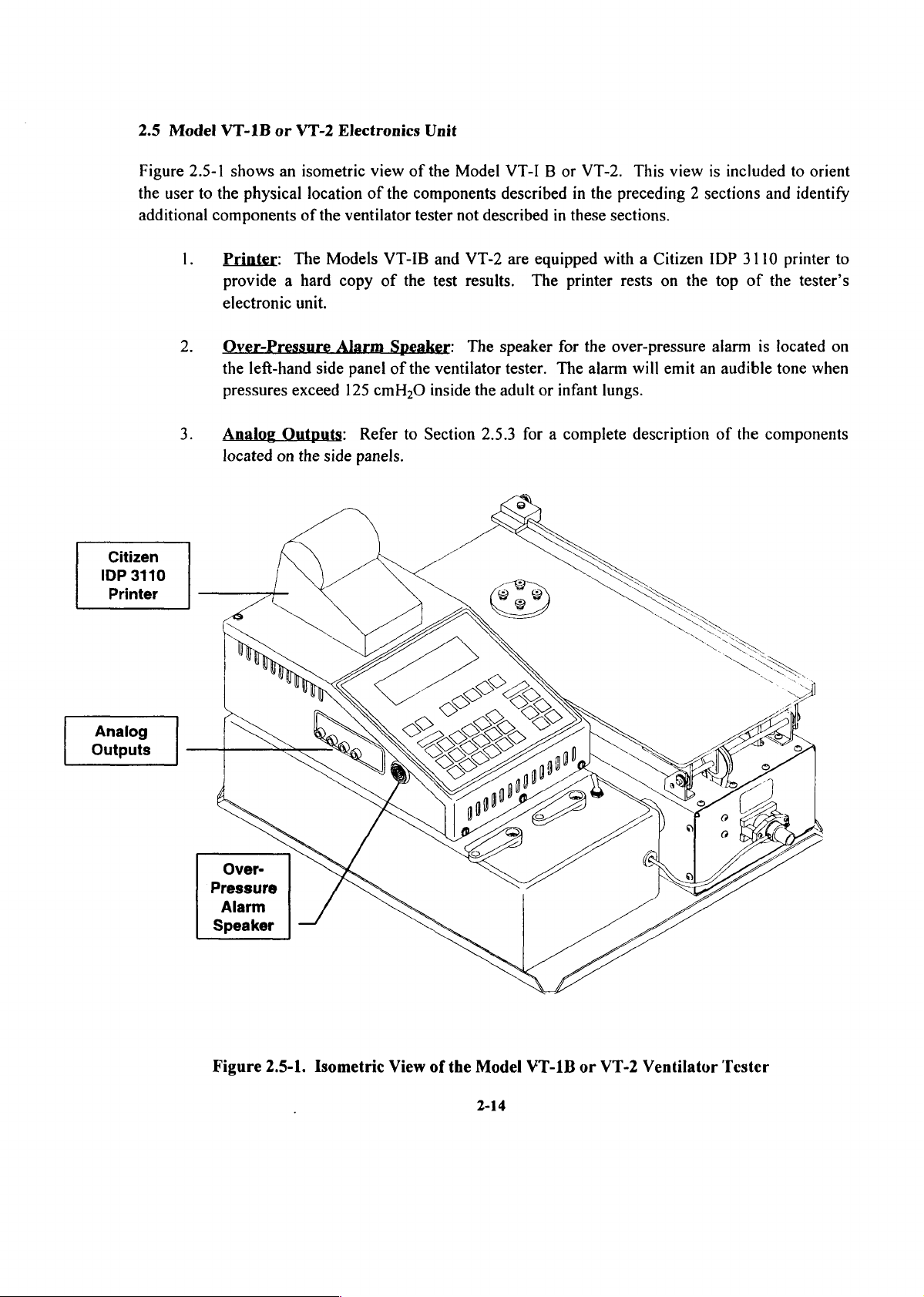
2.5
Model
VT-1B
or
VT-2
Electronics
Unit
Figure
the
additional
Citizen
IDP
3110
Printer
2.5-1
user
1.
2.
3.
shows
to
the
components
Printer:
provide a hard
electronic
Over-Pressure
the
pressures
Analog
located
an
physical
left-hand
Outputs:
on
isometric
location
of
the
ventilator
The
Models
copy
unit.
Alarm
side
panel
exceed
the
125
side
view
of
the
VT-IB
of
the
Speaker:
of
cmH,O
Refer
to
panels.
of
the
Model
components
tester
not
described
and
VT-2
test
results.
The
the
ventilator
inside
the
Section
2.5.3
VT-I B or
described
are
speaker
tester.
adult
for a complete
in
in
these
equipped
The
printer
for
The
or
infant
VT-2.
the
This
view
the
preceding 2 sections
sections.
with a Citizen
rests
on
the
over-pressure
alarm
will
emit
lungs.
description
is
included
IDP
top
alarm
an
audible
of
and
3110
printer
of
the
is
located
tone
the
components
to
orient
identify
to
tester’s
on
when
Analog
Outputs
Pressure
Alarm
Speaker
Figure
2.5-1.
Isometric
View
of
the
Model
2-14
VT-1B
or
VT-2
Ventilator
Tester
Page 30
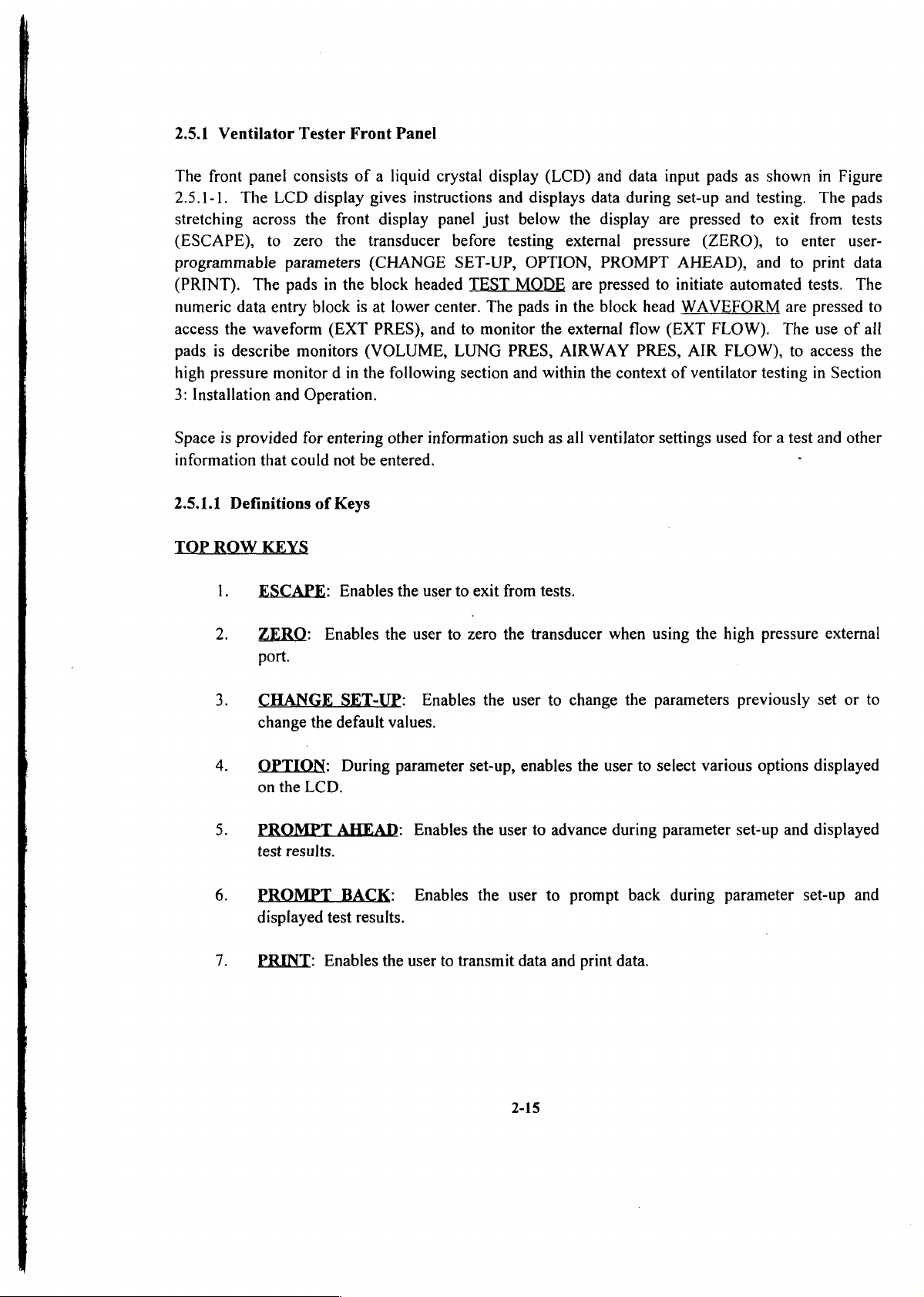
2.5.1
Ventilator
The
front
panel
2.5.1-1.
stretching
(ESCAPE),
programmable
(PRINT).
numeric
access
pads
high
3:
Installation
Space
information
The
across
The
data
the
waveform
is
describe
pressure
is
provided
that
Tester
consists
LCD
to
zero
parameters
pads
entry
monitors
monitor d in
and
for
could
Front
display
the
front
the
in
the
block
(EXT
Operation.
entering
not
Panel
of a liquid
gives
instructions
display
transducer
(CHANGE
block
headed
is
at
lower
PRES),
(VOLUME,
the
be
entered.
and
following
other
information
crystal
panel
center.
display
just
before
SET-UP,
TEST
The
to
monitor
LUNG
section and
and
displays
below
testing
OPTION,
MODE
pads
PRES,
such
(LCD)
the
external
are
in
the
the
external
AIRWAY
within
as
all
and
data
input
data
during
display
PROMPT
pressed
block
the
ventilator
are
pressure
to
head
flow
(EXT
PRES,
context
settings
pads
set-up
AHEAD),
initiate
of
and
pressed
(ZERO),
automated
WAVEFORM
FLOW).
AIR
FLOW),
ventilator
used
as
shown
testing.
to
exit
to
enter
and
to
are
The
to
testing
for a test
in
Figure
The
pads
from
tests
user-
print
data
tests.
The
pressed
use
of
access
in
Section
and
other
to
ail
the
2.5.1.1
TOP
ROW
1.
2.
3.
4.
5.
6.
Definitions
KEYS
ESCAPE:
ZERO:
port.
CHANGE
change
OPTION:
on
the
LCD.
PROMPT
test
results.
PROMPT
displayed
of
Keys
Enables
Enables
SET-UP:
the
default
During
AHEAD:
BACK:
test
the
the
user
values.
parameter
Enables
results.
user
to
to
zero
Enables
set-up,
Enables
exit
the
the
the
from
tests.
the
transducer
user
enables
user
to
user
to
to
change
the
advance
prompt
when
the
user
during
back
using
the
parameters
to
select
various options
parameter
during
high
pressure
previously
set-up and
parameter
external
set
or
displayed
displayed
set-up
and
to
7.
PRINT:
Enables
the
user
to
transmit
data
2-15
and
print data.
Page 31

gi
BIO-TEK
ESCAPE} | ZERO
TEST
sassi
MODE
VENTILATOR
CHANGE]
o
|} 1 |] 2 ||
TESTER
[OPTION]
|FROMET]
3
[PROMETI | PRINT
wue|
WAVEFORM
|
時
TEST | |
REPERTI | TEST | |
Test | |
LEAR | |
ENTER
Figure
4
7
2.5.1-1.
Ventilator
2-16
5
8
6
9
Tester
Keypad
“Pres | |
PRES
tou
FLOW
Page 32

Page 33

TEST
MODE
1.
KEYS
STATUS
some
Minute
readings
adjust
and
2.
FULL
readings
to
the
3.
AUTO-REPEAT:
feature
performance
to
troubleshoot
at
user
4.
ASSIST
Assist-Control
the
lung
the
Minimum
TEST:
key
and
Volume
are
ventilator
can
use
TEST:
pertaining
ones
in
for
preprogrammed
TEST:
would
Assist
Pressure,
Airway
The
commonly
(MV),
updated
controls
this
feature
By
using a single
to
STATUS
Because
other
parameters
over
several
intermittent
The
modes
trigger a breath
of
Pressure.
unit
provides
required
Breath
continuously
to
the
Rate,
to
determine
calibrate
characteristics
TEST.
of
the
and a need
hours
problems,
intervals
tester
tests
ventilators
cycle
positive
or
the
means
information
and
Inspiratory
for
every
optimum
the
ventilator.
key
operation,
of
the
unavailability
to
continuously
or
days
for
repeatability/endurance
the
tester
of
from 5 to
the
120
Sensitivity
where a breathing
from
the
negative
End
of
obtaining
such
as
breath
so
settings
the
delivered
of
the
carries
minutes.
Control
ventilator.
Expiratory
and
Tidal
Flow
user
that
and
can
Volume
Rate.
the
performance
breaths
percentage
monitor
out
the
FULL
and
effort
The
simulated
tester
Pressure,
displaying
(TV),
These
user
can
obtain
in
addition
variation
ventilator
tests
TEST
Assisted
displays
and
all
or
or
by
5.
6.
WAVEFORM
1.
2.
3.
LEAK
lung
and
patient
TREND
instances
between
feature
Tidal
tester
Volume
prints
KEYS
VOLUME:
is
displayed
same
key a second
values
AIRWAY
EXT
mode,
PRES:
from
TEST:
the
tubing
TEST:
where
the
to
monitor
of
the
PRES:
Measures
Model
(use'the
an
user
Variation
out
the
On
selecting
and
selected
Description
General
0-75
psi
the
VT-2
adult
Even
intermittent
programmed
Tidal
with
Volume.
with
Full
Test
any
continuously
time,
Instantaneous,
parameter
purpose
or
equivalent
leak
infant
lung
the
fault
time
respect
values
one
updated
are
the
pressure
rate
of
lung.
only
for
AUTO-REPEAT
in
intervals.
Based
to
the
for a faulty
of
these
every
displayed.
same
as
in
cmH,0.
the
Model
Measures
this
type
ventilator
The
on a user
first
reading
breath.
keys,
the
other
Maximum,
for
VOLUME,
measurements
VT-1B
the
leak
of
LEAK
feature,
performance
tester
programmed
as
corresponding
breath.
and
Minimum
preceding.
can
and
rate
TEST).
there
may
therefore
percentage
the
reference,
By
pressing
be
made
VT-2
of
external
may
occur
waveform
Numeric
in
adult
be
in
has
of
the
the
this
a
4.
LUNG
PRES:
Description
the
same
2-17
as
for
VOLUME,
preceding.
Page 34

5.
6.
AIR
EXT
from
FLOW:
FLOW:
10-75
Description
General
Ipm.
the
purpose
same
flow
VOLUME,
for
as
measurements
preceding.
can
be
made
in
this
mode,
NUMERI
2.5.2
KEY
0,
1.
2.
3.
Ventilator
1.9:
mode.
CLEAR:
ENTER:
advances
Fuses:
(Refer
Power
the
correspond
RS232
female
of
the
This
to
Tester
The
to
Section
Input
line
voltage
Serial
connector.
ventilator
These
key
This
the
Rear
fuses
Jack:
to
common
keys
clears
key
next
Panel
are
2.6:
(on
Port:
This
tester.
can
be
used
wrong
enters
step.
located
Accessories,
The
the
in
power
the
line
usage
in
The
RS232
is a bi-directional
(Refer
to
enter
entries
numeric
the
upper
for
input
voltage
the
user’s
serial
to
Section
preferred
made
values
lefthand
fuse part
jack
that
select
locale.
port
RS232
3.4
during
selected
numbers.)
is
installed,
dial)
on
the
to
for
installation
values
the
set-up
corner
should
rear
enable
during
mode.
during
(see
Figure
the
fuse
be
panel
computer
procedures.)
the
set-up
set-up,
selected
is a 25-pin
2.
>.
size,
control
and
2-1).
and
to
2.5.3
The
faces
Lung.
Ventilator
components
the
1,
Printer
select
ON/OFF
the
display
Analog
electronics
arranged
ver-Pressure
audible
The
Port:
switch
rear
Tester
on
and
alarm
speaker
This
located
Switch:
panel.
Side
the
right
front
Outputs:
unit
are
and labeled
Alarm
in
case
is
shown
is a 36-pin
at
this
The
main
Panels
side
panel
panel
On
the
as
shown
Speaker:
of
in
keypad)
the
analog
lung
Figure
parallel
port.)
power
of
left
outputs
in
The
over-pressurization
2.5-1.
2-18
is
the
have
side
Figure
Centronics
toggled
Model
been
panel
for
2.5.3-1.
speaker
connector.
ON
and
VT-1B
described
connection
on
of
or
the
the
(greater
OFF
VT-2
in
Section
Model
to a chart
left
side
(Note
by
(when
VT-1B
panel
than
the
switch
the
2.4.1:
125
the
mode
on
viewer
Adult
or
VT-2
recorder,
emits
an-
cmH,0).
o
Page 35

Figure
2.5.3-1.
Model
VT-1B
2-19
or
VT-2
Analog
Outputs
Page 36

2.6
Accessories
Accessories
included
Bio-Tek
2.7
Optional
in
Table
in
part
Optional
accessories
2.7-1.
for the
an
accessories
numbers
Accessories
(not
Model
to
be
VT-IB
pouch
used
provided
that
for
with
or
ordering
VT-2
accompanies
the
(with
are
unit
the
the
listed
unless
exception
unit.
requested
in
The
Table
of
this
accessories
2.6-1.
by
the
user)
manual)
and
are
are
their
listed
2-20
Page 37

Bio-Tek
Part
Number
Quantity
Supplied
Table
2.6-1.
Description
Models
VT-IB
and
VT-2
Accessories
6770042
91068
8802025
75004
97128
97129
8810114
48129
48130
48131
48163
48323
1
1
hs
ui
=
—
Accessories
Shipping
Carrying
IBM
Printer
Citizen
Printer
Centronics
Parabolic
Rps
Rp20
p50
Rp200
Rpsoo
box
case
male-female
Şu
IDP
paper
Airway
(for
VT-2)
(for
VT-2)
box
serial
t
3110
printer,
roll
for
printer
Restrictors:
Citizen
cable
interface
with
(parallel,
cable
instruction
male-male)
manual
and
power
supply
75010
75011
75012
75013
48023
46028
8810131
49342
8801000
Power
Cord
European
(one
of
(“Schuko”
the
following):
and
French)
U.S.
United
Kingdom
Australian
Fu
.75A
3AG
ya
—
375A
On/off
Adapter,
Operator's
Slo-Blo
3AG
valve
rubber
Manual
Slo-Blo
(for
h
(100
(230
patient
hose
and
125
VAC
tubing)
VAC
usage)
usage)
2-21
Page 38

!
Bio-Tek
Part
Number
Table
2.7-1.
Description
Models
VT-1B
and
VT-2
Optional
Accessories
|
|
--
48133
48134
INFANT
The
compliance
VT-2,
can
specifications
Model
however,
be
purchased
LUNG
VT-2
between
meet
at
Port
Adapters:
Hudson
Ohio
OPTIONS
normally
717
our
on a made-to-order
other
VT-2
VT-2
VT-2B
VT-2C
VT-2D
VT-2E
VT-2F
VT-2G
VT-2H
O,
O,
port
TO
supplied
and
777
published
altitudes
Model
(Standard)
port
adapter
adapter
MEET
has
mmHg
specifications.
are
needed.
ANSI
infant
only.
basis
COMPLIANCE
lungs
if
Atmospheric
717
699
681
664
646
628
611
593
Actual
The
infant
--777
--
757
--
738
--
719
--
700
--
680
--
661
--
642
that
FOR
meet
readings
following
lungs
Pressure
mmHg
mmHg
mmHg
mmHg
mmHg
mmHg
mmHg
mmHg
HIGH
ANSI
obtained
models
that
Range
ALTITUDES:
specifications
by the
(B
through
comply
with
for
Model
H)
ANSI
2-22
Page 39

3
INSTALLATION
AND
OPERATION
Before
should
1.
2.
3.
4.
3.1
Preparation
Follow
overlay
installing
observe
Ensure
Ensure
Remember
temperature,
provide
through
Remember
front
accepts
accept
the
user
is
sounded.
VT-2
the
procedure
on
the
and
the
following:
that
that
quantitative
the
that
panel,
the
the
input
wishes
has
not
for
Use
Model
operating
the
tester
all
safety
that
the
humidity,
use
of
when
an
audible
user’s
input, a high
(because
to
enter
Absence
detected
below
to
VT-1B
the
is
inspected
precautions
analog
and
data
an
oscilloscope
the
is
of
any
any
prepare
or
VT-2
Model
VT-1B
as
are
waveform
atmospheric
sufficient
or
user
presses
tone
is
produced.
beep
an
inappropriate
out
of
the
audible
input.
the
instrument
electronics
or
VT-2
described
followed
outputs
pressure;
to
support
high-speed
any
keypad
is
sounded.
key
acceptable
tone
signifies
for
unit
as
Ventilator
in
Section
(refer
If
are
therefore,
detailed
chart
on
the
If
the
is
pressed
range
to
recorder.
Model
that
use.
(Refer
described
Tester,
1.
Section
not
compensated
measurements
the
ventilator
VT-IB
instrument
or
because
of
values), a low
the
Model
to
the
in
Section
4.1).
they
VT-1B
rear
2.5.2.)
the
do
or
does
the
user
for
not
made
tester
VT-2
not
data
beep
or
panel
1.
Remove
2.
Using a coin
Model
3.
Connect
VT-1B
4.
Flip
to
ON.
second,
VT-1B
the
the
the
or
VT-2
ON/OFF
The
then
power
or
or
power
display
the
cord
from
screw
VT-2
driver,
electronic
cord
from
electronics
switch
should
display
SET-UP
Use
Use
should
numeric
PROMPT
the
accessories
unit
at
select
the
the
unit.
to
back
the
power
the
wall
of
show a copyright
show:
Time:
keys
key
12:00
to
to
3-1
bag.
proper
input
outlet.
the
ventilator
AM
enter
value.
advance.
line
voltage
jack
at
message
at
the
back
the
back
of
tester
electronics
for a fraction
the
of
the
Model
unit
of
a
Page 40

If
it
does
Make
plate
are
Make
adult
If
you
1)
Plug
2)
Connect
the
not,
sure
the 4 screws
tightly
sure
the
lung
is
will
be
the
back
the
unit
may
on
screwed
transparent
not
loose.
using
the
printer:
printer
the
of
power
printer
the
printer.
cable
be
malfunctioning.
the
round
plate
on.
tubing
attached
supply
to
the
into
printer
the
Call
sealing
to
the
sliding
wall
outlet.
port
on
1-800-451-5172
the
gas
port
on
the
airway
back
adapter
of
the
for
help.
the
top
of
the
on
the
electronics
adult
front
of
unit
and
lung
the
to
NOTE:
3)
Turn
the
check
the
the
printer's
NOTE:
If
desired,
electronic
connections.
Record
temperature
humidity
3.2
Operating
The
Models
microprocessor-based
Precautions
VT-IB
Select a vibration-free
Avoid
attach a chart
unit.
(or
approximate)
of
and
technologies.
operating
The
connector
printer
Ensure
of
the
VT-2
ON
connections
operator's
that
The
overlay
the
gas
air.
incorporate
the
tester
will
and
push
made
manual.
the
printer
recorder
on
the
atmospheric
to
be
used.
sensitive
Observe
surface
in
on
an
engage
PAPER
above.
is
to
the
the
unit
If
you
the
following
which
area
with
in
only
one
FEED.
If
the
printer
on-line.
analog
near
mechanical,
to
output
the
jacks
pressure
will
be
precautions
place
the
high
electromagnetic
orientation.
If
the
printer
still
does
jacks
on
shows
of
the
environment.
using
room
pneumatic,
to
Model
VT-IB
does
not
not
work
the
left
side
where
to
make
Record
air,
record
electronic,
ensure
interference.
proper
or
VT-2
the
work
properly,
properly,
of
the
the
the
relative
and
and
safe
tester.
refer
to
3-2
Page 41

3.3
3.
Set-Up
Do
not
test a ventilator
will
cause
VT-1B
or
of
User-Programmable
incorrect
VT-2
lungs.
while a heated
readings
and
Parameters
humidifier
condensation
is
connected
problems
within
to
the
it.
Model
This
Before
be
used
1.
2.
3.
4.
5.
6.
7.
8.
The
parameters
VT-1B
display.
should
testing
by
the
Date
Compliance
Ventilator
Atmospheric
Relative
Temperature
Reference
Units
or
VT-2
Once
take
less
the
ventilator,
tester
and
humidity
in
which
are
unit
the
user
than
to
make
time
setting
ID
pressure
of
units
entered
front
one
the
calculations
of
the
ventilator
(ATPD,
pressure
by
panel
is
familiar
minute.
user
the
ventilator
ATPS,
values
pressing
in
response
with
must
source
define
and
ATPX,
are
the
the
the
to
display
source
to
light
to
procedure,
gas
STPD,
be
displayed
grey
prompts
gas
following
data:
BTPS,
(cmH,O
numeric
on
the
the
complete
parameters,
NTPD)
or
keypads
Model
mmHg).
on
VT-1B
sequence
which
the
or
of
will
Model
VT-2
steps
NOTE:
BACK
Follow
state
of
i.
At
key
the
the
Make
3.3.
for use
any
to
go
to a previous
sequence
Model
sure
If
time
during
of
VT-IB
you
you
are
(Section
the
page.
steps
below
or
VT-2
have
completed
entering
3.3),
SET-UP
the
SET-UP
Use
Use
to
set
display
the
this
set-up
following
numeric
PROMPT
procedure,
up
the
is
shown
procedures
sequence
display
Time:
key
key
3-3
the
user
can
user-programmable
before
should
12:00
to
to
each
defined
directly
AM
enter
advance.
step.
in
after
appear:
value.
press
parameters.
Sections
preparing
the
3.1
PROMPT
through
the
The
unit
|
e
E
Page 42

a.
If
interacting
you
want
to
with
enter
the
this
unit,
set-up
press
sequence
ESCAPE.
to
change a parameter
The
display
should
after
show:
2.
b.
Press
the
Press
ENTER
example:
CLEAR
EXAMPLE:
The
display
CHANGE
last
0:xx
to
re-enter
set-up
to
enter
will
Time
should
SELECT
SET-UP.
procedure.
the
be
read
the
correct
is
2:06
PM.
SET-UP
Use
Use
show:
SET-UP
The
time
in a 12-hour
as
12:xx.
time.
Enter
numeric
PROMPT
TEST
time
206.
Time:
Time:
displayed
If
an
02:06
key
to
key
to
12:00
will
format
invalid
AM
enter
value.
advance.
AM
be
(i.e.,
time
the
time
0:00
to
12:59).
was
entered , press
entered
in
For
3.
If
applicable,
press
OPTION
EXAMPLE:
NOTE:
changed
Once
by
change
again).
PM
the
is
set,
user
Invalid
"AM"
desired.
SET-UP
the
internal
or
until
TO
Press
the
time
"PM"
OPTION,
Time:
clock
unit
3-4
was
by
pressing
will
is
switched
entered.
02:06
PM
keep
OPTION.
running
off.
(To
return
until
the
to
AM,
time
is
Page 43

4.
Press
PROMPT
AHEAD
or
ENTER
to
enter
the
date.
Enter
from
Ol
month
CLEAR
Press
CLEAR
EXAMPLE:
6-digit
to
12.
entered.
and
date
in
Date
Any
re-enter;
and
enter
Date
is
SET-UP
Use
Use
the
form
number
2-digit
the
display
SET-UP
Invalid
correct
September
Date:
numeric
Prompt
must
year
24,
keys
to
advance.
[Month/Day/Year].
be
is
acceptable.
will
show:
Date:
date
was
date.
1985.
MM/DD/YY
to
enter
within
MM/DD/YY
entered.
Enter
value.
maximum
If
you
092485.
Month
number
number
make a mistake,
of
must
days
be
for
press
Press
PROMPT
Move
required.
step.
asterisk
If
AHEAD
next
the
asterisk
SET-UP
SET-UP
Units
Use
Use
to
or
ENTER.
OPTION
PROMPT
desired
is
already
Date:
The
Compliance:
in
L/cmH,O
key
compliance
next
09/24/85
display
to
key
to
to
should
*.05
02
01
003
001
change
advance.
value
the
desired
show:
setting.
by
pressing
value,
OPTION
go
to
the
as
next
Page 44

NOTE:
VT-2
settings,
By
lung
The
only.
selecting
conditions
.003
If
you
these
test
appropriate
and
.001
have a Model
readings
compliance
such
as
those
compliance
VT-IB
will
not
be
shown
in
values
Adult
Ventilator
displayed.
and
resistor
Table
are
for
values,
3.3-1.
the
infant
Tester and
the
user
lung
application
you
select
can
simulate a spectrum
the
of
the
.003
Model
or
.001
of
|
Condition
AdulvPediatri
Normal
Pneumothorax
Asthma
COPD
Collapsed
Emphysema
Normal
Infant
Newborn
|
Post-operative
Hyalin
Intubated
Premature
Premature
or
Bronchitis
(Chronic
Pulmonary
Lung
Pediatric
(2.8
Disease
(1.35 — 2
3 — 4.5
Ib)
Extreme
Obstructive
Disease)
kg, 6 Ib)
kg,
Table
3,3-1.
Simulated
Compliance
0.05
0.02
or
0.05
0.02
0.01 20
0.01
0.01
0.003
0.003
or
0.001
0.003
0.003
0.001
0.01
0.001
Patient
(C)
Conditions
Airway
Resistor
20
20
50
50
50
20
50
50
200
200
or
500
50
200
(R)
ГО
Lhm
Page 45

EXAMPLE:
Compliance
desired
is
0.02
L/cmH,0.
Press
OPTION
once.
Ensure
compliance
a.
Adult:
ADULT/INFANT
see
Figure
1.
Move
matching
appropriate
2.
Move
of
one
that
the
quarter
the
you
the
the
spring;
Ensure
2.4,2-2)
adult
selected
that
lung
are
compliance
compliance
compliance
spring
unscrew
of a full
SET-UP
Units
or
in
Step
selector
in
by
unscrewing
turn.
Compliance:
in
L/cmH,O
infant
7,
the
ADULT/INFANT
the
ADULT
spring
by
position
the
lung
compliance
preceding.
(located
positions.
on
the
right
positioning
on
the
the
knob
counterclockwise
under
top
black
05
*02
01
003
001
side
the
of
knob
setting
toggle
the
of
spring
the
on
VT-2
the
adult
the
(towards
matches
switch
electronics
adult
lung
pointer
lung.
righthand
the
and
box
to
the
to
the
side
yourself)
3.
Hold
the
spring
assembly
position
4.
Tighten
position
NOTE:
the
other
too
tight,
been
compliances.
unit
set
has
years.
If
you
inaccurate,
the
problem.
Department
1-800-451-5172
recalibration.
top
and
is
in a vertical
until
and
the
as
the
black
you
the
do
Under
screws
or
has
with
Unlcss
been
dropped,
suspect
that
first
If
Hotline
bottom
spring
top
assembly
knob;
this.
NO
conditions
or
mechanical
extra
precision
the
refer
this
to
determine
space
your
to
at:
portions
position);
pointer
clicks
ensure
that
should
parts
below
at
the
spring
the
was
lung
volume,
Section
is
not
successful,
1-800-24-BIOTK
of
the
spring
use
both
is
over
the
into a notch.
the
spring
you
cven
if
its
lower
factory
damaged
should
5:
whcther
remain
flow,
Troubleshooting,
your
assembly
hands.
appropriate
remains
unscrew
the
guide
to
attain
or
calibrated
and
pressure
call
or
Customer
adult
or
spring
rail.
bent
the
(note
Then
in
the
tighten
appears
The
correct
in
transit
readings
to
try
Bio-Tek
Service
lung
that
the
move
compliance
the
vertical
any
loose,
spring
for
or
several
to
locate
Service
has
lung
the
are
requires
of
at:
Page 46

9.
b.
Infant:
Press
1.
Switch
lung
2.
Switch
3.
Switch
underneath
SET-UP.
PROMPT
The
the
selector
the
the
AHEAD
following
ADULT/INFANT
lever
under
ADULT/INFANT
INFANT
the
electronic
or
steps
apply
the
COMPLIANCE
ENTER;
to
toggle
clectronic
airway
box)
to
the
the
Model
switch
lever
lever
the
compliance
display
box
to
should
VT-2
and
the
to
the
INFANT.
(located
show:
only.
ADULT/INFANT
infant
you
positions.
in
front
selected
of
in
and
이
an
ene
10.
11.
Enter
mistake,
EXAMPLE:
Press
ID
PROMPT
number
press
Ventilator
(up
CLEAR
AHEAD
SET-UP
Use
numeric
Use
PROMPT
to
16
and
ID
SET-UP
or
SET-UP
Vent.
key
digits)
re-enter.
is
#1256.
Vent.
ENTER.
Atmos.
ID:
to
key
to
of
ventilator
Enter
ID:
1256
Pressure:
enter
advance.
1256.
value.
to
be
760
tested.
mmHg
If
you
make
a
12.
Enter
mistake,
already
atmospheric
press
CLEAR
shown
on
Use
Use
pressure
and
the
display,
numeric
PROMPT
of
re-enter.
go
keys
key
test
environment
to
the
3-8
to
enter
to
advance.
If
the
following
value.
in
atmospheric
Step
mmHg.
pressure
13.
If
you
is
make
the
a
value
Page 47

NOTE:
using
lung
displayed
specifications
lungs
It is
the
infant
compliances
readings
necd
to
very
at
mect
important
lung
section
mect
even
other
ANSI
to
enter
of
ANSI
atmospheric
standards
if
the
infant
standards
the
the
Model
up
lungs
conditions.
beyond
correct
VT-2.
to
777
themselves
these
atmospheric
The
mmHg
Call
Bio-Tek
limits.
Model
and
may
pressure
VT-2
will
not
mect
if
your
not
when
infant
affect
ANSI
infant
EXAMPLE:
show:
NOTE:
show:
If
you
wish
pressure.
Atmospheric
If
you
you
SET-UP
Use
Use
enter
SET-UP
Value
can
pressure
Atmos.
numeric
PROMPT
outside
Atmos.
entered
use
the
is
Pressure:
keys
key
of
the
Pressure:
was
default
720
mmHg.
to
enter
to
advance.
valid
invalid.
value
720
values.
range
of
Enter
mmHg
(600
760
720;
to
800)
mmHg
the
display
the
display
for
atmospheric
will
will
13.
Press
relative
NOTE:
50%,
PROMPT
as
humidity:
The
range
shown
in
AHEAD
SET-UP
Use
Use
for
the
or
R.H.:
numeric
PROMPT
relative
preceding
ENTER;
50%
keys
key
humidity
display.
3-9
the
to
enter
to
advance.
display
value.
is 0 to
100%
will
and
show
the
the
prompt
default
value
for
is
ーー
Page 48

a.
If
you
enter a number
exceeding
this
range,
the
display
will
show:
14.
b.
Enter a valid
Enter
if
mistake,
value
CAUTION:
EXAMPLE:
relative
you
relative
are
(50%)
humidity
using a wall
press
CLEAR
already
Do
Room
humidity
SET-UP
Value
number
shown
not use a heated
air
is
75%.
SET-UP
RH:
entered
and
of
the
outlet
and
on
is
to
Enter
RH:
press
or
re-enter.
the
be
was
invalid.
ENTER.
ventilator
tank(s)
If
display,
humidifier
used
as
75.
75%
source
as
the
the
go
at
the
gas
gas
source(s).
relative
to
the
following
any
time.
ventilator
(from 0 to
humidity
Step
gas
source,
100).
If
is
you
the
15.
Enter
make
default
and
its
0
a
15.
16.
Press
Enter
CLEAR
PROMPT
Only
shown
EXAMPLE:
the
AHEAD
SET-UP
Use
Use
the
temperature
values
and
on
the
15°
re-enter.
display),
Gas
temperature
SET-UP
or
numeric
PROMPT
(in
to
50°
If
go
ENTER.
Gas
degrees
will
the
to
the
Gas
Temp:
keys
key
be
gas
temperature
next
is
30°
Temp:
3-10
25
deg
to
enter
value.
to
advance.
centigrade)
accepted.
is
step.
centigrade.
30
deg
C
C
If
of
you
the
Enter
the
ventilator
make a mistake,
default
value
30.
source
(25°
gas.
press
already
Page 49

17.
Press
PROMPT
AHEAD
or
ENTER.
NOTE:
to a ventilator’s
the
ventilator.
with
this
18.
Move
example)
asterisk
acceptable,
reference
EXAMPLE:
twice
asterisk
to
When
information;
for
is
units.
move
comparing
The
next
Minute
already
go
to
If
the
settings,
ATPD
SET-UP
Minute
Use
OPTION
Use
PROMPT
ventilator
if
to
Volume
next
to
the
next
asterisk
SET-UP
Minute
Ref.
Vol.
Only
Model
it
is
important
not,
call
desired
the
units
step.
reference
next
to
Ref.
Vol.
Only
Units:
key
key
VT-1B
manufacturer
Bio-Tek’s
reference
by
Refer
units
ATPD.
Units:
ATPD
ATPS
ATPX
to
change
to
advance.
to
pressing
desired
to
are
*ATPD
ATPS
ATPX NTPD
or
STPD
*BTPS
NTPD
setting.
VT-2
select
Biomedical
units
OPTION
or
Table
desired,
volume
the
should
(defined
if
the
3.3-2
STPD
BTPS
and
flow
same reference
be
able
to
Product
as
default
for
press
Manager.
in
the
required.
setting
definitions
the
OPTION
readings
units
provide
following
If
(BTPS)
of
as
you
the
is
the
key
19.
Press
PROMPT
AHEAD
SET-UP
Other
Use
Use
or
ENTER.
Ref.
Vol & Flows
OPTION
PROMPT
Units:
key
to
key
ATPD
ATPS
*ATPX
change
to
advance.
STPD
BTPS
NTPD
setting.
Page 50

Table
3.3-2.
Reference
Units
Defined
|
|
Reference
Unit
ATPD
ATPS
ATPX
BTPS
|
NTPD
STPD
|
|
|
ATPD
ATPS
ATPX
BTPS
NTPD
STPD
=>
=>
=>
=>
=>
=>
20.
Ambient
Ambient
Ambient
Body
Normal
Standard
Move
readings
Flow)
units
Temperature
Ambient
Ambient
Ambient
37° C (body)
20°
C
ος
temperature
temperature
temperature
temperature,
temperature
temperature
asterisk
(¢.g.,
by
desired
next
Tidal
pressing
or
ambient
OPTION
if
the
and
and
and
and
pressure,
and
to
desired
Volume,
default
pressure,
pressure,
pressure,
pressure,
pressure,
reference
Baseline
as
required.
(ATPX)
Pressure
Ambient
Ambient
Ambient
Ambient
760
mmHg
760
mmHg
dry
air
saturated
existing
saturated
dry
air
dry
air
Volume,
If
is
acceptable,
air
humidity
air
units
the
asterisk
for
Inspiration
Relative
Humidity
0%
100%
Ambient
100%
0%
0% (Dry)
other
is
proceed
(Dry)
(Saturated)
(Saturated)
(Dry)
volume
and
already
to
the
and
flow
Expiration
next
to
the
next
step.
NOTE:
to a ventilator’s
the
ventilator.
with
EXAMPLE:
the
asterisk
When
this
information;
NTPD
moves
comparing
settings,
The
ventilator
if
reference
next
SET-UP
Other
Model
it is
important
manufacturer
not,
call
units
to
NTPD.
Ref.
Units:
Vol & Flows
3-12
VT-1B
Bio-Tek’s
are
or
to
desired.
ATPD
ATPS
ATPX
VT-2
select
Biomedical
volume
the
should
Press
STPD
BTPS
*NTPD
same
be
able
Product
OPTION
and
flow
reference
to
provide
Manager.
3
readings
units
times
as
you
until
Page 51

21.
Press
PROMPT
AHEAD
or
ENTER.
22.
Move
except
asterisk
acceptable,
EXAMPLE:
Press
asterisk
High
is
already
proceed
OPTION
SET-UP
Use
Use
next
to
External
next
to
It is
desired
key
twice.
SET-UP
Pres.
OPTION
PROMPT
the
units
Pressure
to
the
next
to
Pres.
the
have
Units:
key
key
desired
by
units
step.
all
Units:
mmHg
*cmH20
kPa
to
change
to
advance.
pressing
desired
pressure
mmHg
*cmH20
kPa
for
setting.
all
measured
OPTION
or
if
readings
the
pressure
as
required.
default
displayed
readings
If
(cmH,0)
in
mmHg.
the
is
23.
24.
Press
If
you
a.
b.
PROMPT
desire a printout
Make
Section
Make
sure
3.1).
sure
AHEAD
Print
Use
Use
the
the
Set-Up?
OPTION
PROMPT
of
printer
printer
or
ENTER.
the
is
correctly
contains
‘yes
key
key
set-up
3-13
no
to
change
to
advance.
parameters:
hooked
at
least 4 inches
setting.
up
and
of
powered
paper.
on
(refer
to
Page 52

c.
Press
PROMPT
Citizen
printer
AHEAD.
included
with
The
printout
the
will
take
ventilator
tester.
less
than
20
seconds
using
the
25.
If
you
NOTE:
data,
the
Section
A
printout
do
not
If a computer
computer
3.4
for
installation
of
the
desire a printout
is
screen
sample
SETAP
Vent.
ID:
Compliance = .05
Atmos.
RH.
=50%
Gas
Temperature = 25
Ref.
Units
Ref.
Units
Pres.
Units = caM20
Figure
connected
will
procedures.)
set-up
132645
Pressure = 760
(Minute
(Other
3.3-1.
of
to
display
just
completed
Vol.
Vol 4 Flows) = ATPX
Set-Up
the
set-up
the
Model
the
same
ang
deg
C
У) = BTPS
Printout
parameters:
VT-1B
messages
is
shown
02/04/96
2:29
M
or
VT-2
as
in
Figure
and
the
printout.
3.3-1.
set
up
to
accept
(Refer
to
26.
a.
b.
The
Press
OPTION
Press
PROMPT
display
should
to
advance
AHEAD.
now
show
asterisk
the
message:
Please
warm-up
wait
Time
next
to
"no"
until
15-minute
period
remaining:
is
complete.
xx:xx.
on
display.
3-14
Page 53

The
time
remaining
is
updated
every
second.
NOTE:
up
longer
15
was
transported
If
sufficient
he
ventilator
been
bypass
step.
At
appear
The
27.
The
is
about
it
will
minutes
recently
the
unit
cannot
warmed
the
the
end
automatically.
following
temperature
38°
C.
take
is
recommended
switched
in a very
has
recently
warm-up
wait
the
connection
up
sufficiently,
warm-up
of
the
message
PLEASE
The
to
reach
ON
cold
period,
full
and
period,
warm-up
should
inside
colder
environment,
this
from
and
is
been
or
if
15
minutes,
testing
however,
press
period,
now
ZERO
the
the
temperature.
room
still
switched
the
(Sections
ESCAPE,
THE
electronics
unit
temperature
warm.
a
longer
user
decides
it
test
the
display
appear:
TRANSDUCERS
is
when
off
is
possible
3.5
results
then
unit
A
minimum
If
the
warm-up
after
and
shown
when
it
(25°
unit
for
3.6).
may
ZERO,
it is
is
first
C),
has
is
having
some
to
proceed
If
not
and
in
the
fully
turned
warm-up
unless
been
stored
recommended.
been
on
other
the
be
accurate.
go
next
reason
directly
unit
to
step
warmed
on, the
time
the
unit
for
that
has
not
the
next
will
of
or
a
to
To
28.
29.
Any
or
following
1.
2.
Make
to
the
Press
followed
Proceed
VT-2
Section
all
of
the
Press
Press
sure
lung,
ZERO.
by
to
lung.
3.6:
the
sequence
ESCAPE.
CHANGE
Vent
the
then
press
the
lungs
disconnect
SELECT
Section
If
Ventilator
user-programmable
of
The
you
steps
SET-UP
are
TEST.
3.5:
have
below:
vented
it.
message
already
Tests.
to
lung
to
ZERO.
to
atmosphere.
TRANSDUCERS
Connecting
properly
parameters
enter
the
atmosphere;
the
ventilator
connected
can
set-up
sequence.
If
patient
be
ZEROED
to
the
the
ventilator,
changed
tubing
should
Model
at
is
connected
proceed
any
appear,
VT-IB
time
or
to
by
3-15
Page 54

3.
Press
wish
4.
Make
5.
Press
changes,
6.
Press
3.4
Setting
The
Model
Tester
switching
computer
TEST,
automatically
function
cannot
have
can
and
key.
be
displayed
PROMPT
to
the
PROMPT
ESCAPE
Up
the
VT-1B
computer
the
testers
be
MONITOR
on
The
change.
desired
proceed
Models
Adult
control
ON,
used
to
modes.
the
computer
waveforms
on
AHEAD
change.
AHEAD
to
Step
to
exit
VT-1B
Ventilator
capability
either
control
AIl
the
computer
repeatedly
to
6,
below.
from
the
and
Tester
the
tester
or
access
readings
screen
displayed
screen.
continue
sequence
VT-2
for
and
(provided
information
appearing
so
that
on
to
through
Computer
the
front
it is
the
page
through
the
entirely.
Control
Model
by
panel
Models
VT-2
the
bi-directional
keys
from
on
the
mot
necessary
to
sequence
Adult/Infant
or
the
tester
tester
VT-IB
the
parameter
to
make
Applications
RS232).
specified
during:
display
to
and
also
press
VT-2,
you
other
Ventilator
After
keys
on
SET-UP,
appear
the
PRINT
however,
a
Table
feature
computer
You
have
Description,
ready
3.4-1
as
are
now
used a Bio-Tek
to
begin
gives
well
as
keyboard
ready
to
learn
operating
pertinent
the
data
input
to
set
Ventilator
the
information
communication
commands
up
the
ventilator
Tester,
location
the
unit,
and
please
and
proceed
about
protocol
the
waveform
test
function
to
Section
the
ventilator
required.
parameters.
read
Section
of
all
3.5.
monitor
If
2:
of
the
tester
Table
modes.
this
Models
components.
computer
3.4-2
is
the
identifies
first
VT-1B
time
and
If
control
the
you
VT-2
you
are
3-16
Page 55

Table
3.4-1.
Data
Communication
Protocol
and
Computer
Control
Requirements
Table
Keyboard
Baud
Receiving
Transmitting
RS232
Program:
3.4-2.
Rate
Port:
Computer
VT-1B/VT-2
TOP
DATA
Port
Port
COMPUTER
IBM
RS232
Use any
MESSAGE,
Keyboard
COMPUTER
LINE
COMMUNICATION
2400
1
1
CONTROL
PC
compatible,
25-pin
D-type
Asynchronous/Serial
O-MODEM,
Input
KEYBOARD
REQUIREMENTS
25-pin
male-female
CROSSTALK)
Commands
INPUT
K
b
PROTOCOL
Parity
Data
Stop
D-type
female
(Bio-Tek
Communications
and
Waveform
COMMANDS
Γ
ou
Bits
Bits
ton
connector.
part
program
Monitor
VT-1B/VT-2
NUMERICAL
(Light
Grey
oo
#75004)
(e.g.,
Modes
SECTION
Area)
の
内
ヨガ
ゴ
の
で
zo>zmw
<
ог
ESCAPE
ZERO
CHANGE
OPTION
PROMPT
PROMPT
PRINT
TEST
MODES
STATUS
FULL
AUTO
ASSIST
TEST
REPEAT
TEST
LEAK/COMP
TREND
VOLUME
LUNG
PRESSURE
AIRWAY
SET-UP
FORWARD
BACK
TEST
TEST
TEST
WAVEFORM
PRESSURE
ロー
ら
ー
らら
よら
は
ひみ
oo
MONITOR
J
H
o
3-17
MODES
CLEAR
ENTER
NUMBER
NUMBER
NUMBER
NUMBER
NUMBER
NUMBER
NUMBER
NUMBER
NUMBER
NUMBER
AIR
EXT.
EXT.
0
I
2
3
4
5
6
7
8
9
FLOW
PRESSURE
FLOW
Page 56

3.5
Connecting
the
Ventilator
to
the
Model
VT-IB
or
VT-2
Lung
NOTE:
testers
Follow
.
The
will
the
Model
display
sequence
ilator:
Connect
Remove
IT
TIENT- Y TO
If
restrictor
both
If
R,
minute.
are
Refer
illustration
VT-IB
or
readings,
of
steps
the
the
IS
RECOMMENDED
you
will
to
ends
and a length
you
are
not
200
Ryser
Refer
provided
to
the
VT-2
cannot
test
high
although
below
patient
breathing
be
be
R,,
in
Figure
to
their
accuracies
to
connect
tubing
mask
AVOID
following a ventilator
used
with a lung
following
And
R,,)
to
Table
Section
3.5-1
perform
the
the
circuit
from
TO
CROSS-CONTAMINATION
comparable
such a protocol,
from
the
3.3-1
for
2,
Table
for
an
following
frequency
ventilator
to
the
ATTACH A STANDARD
manufacturer’s
model,
to
accessories
simulated
2.4.1-1.
illustration
Steps 7 through
(>75
BPM)
cannot
be
guaranteed.
to
be
tested
the
ventilator
patient-Y
select a connector
that
of
select
patient
of
as
of
the
the
parabolic
one
of
box.
The
conditions.
the
restrictor
test
10.
ventilators
to
the
Model
required.
patient
the
tubing
BACTERIA
BETWEEN
protocol
piece
baving a 15mm
airway
parabolic
restrictor
Parabolic
and patient-y
or
Jet
ventilators;
VT-IB
circuit.
FILTER
VENTILATORS.
that
does
not
restrictors.
airway
values
restrictors
are
given
restrictor
connection.
or
VT-2
TO
call
outer
in
pressure
however,
lung
THE
for
any
diameter
(R_.,
cmH.
Refer
the
before
PA
airway
at
Oftiter/
drops
to
this
10.
11.
12.
Pull
out
It
should
the
airway
Insert
either
Push
in
so
that
it
Connect
Select
the
LATOR
Proceed
the
sliding
pull
inlet.
the
sliding
is
snugly
the
desired
HUMIDIFIER.
to
Section
adapter
out
far
end
of
the
adapter
connected
patient-y
settings
3.6
enough
parabolic
until
to
the
on
to
test
on
the
to
allow
airway
the
to
the
sliding
the
ventilator
the
ventilator.
front
of
the
the
parabolic
restrictor
resistor’s
parabolic
adapter.
and
Model
airway
or 15
center
airway
switch
VT-IB
or
restrictor
mm
connector
is
flush
inside
restrictor
it
on.
DO
VT-2
of
or
15
NOT
adult
lung
or
15
mm
into
the
adult
mm
connector).
SWITCH
as
far
connector
the
airway
lung
front
ON
as
THE
it
will
to
fit
inlet.
inlet
(i.e.,
VENTI
go.
into
3-18
Page 57

Parabolic
Restrictor
Airway
Airway
dina
Sliding
Inlet/
A
Adapter
Figure
3.5-1.
Restrictor
and
Patient-Y
Connection
Patient
-Y
3-19
Page 58

3.6
Ventilator
This
section
VT-1B
3.6.1
Status
3.6.2
Full
3.6.3
Auto-repeat
3.6.4
Trend
3.6.5
Assist
3.6.6
Leak
3.6.6.1
3.6.6.2
3.6.6.3
3.6.6.4
Tests
describes
and
VT-2:
test
test
test
test
and
compliance
Model
leak
test
Patient
Patient
Ventilator + patient
compliance
full
VT-1B
tubing
tubing
the
test
test
various
tests
or
VT-2
leak
test
compliance
tubing
test
lung
and
test
monitor
3.6.7
3.6.7.1
3.6.7.2
3.6.7.3
3.6.7.4
3.6.8
3.6.8.1
3.6.8.2
modes
Waveform
Volume
Airway
monitor
Lung
monitor
Air
External
External
External
and
flow
available
monitor
waveform
pressure
pressure
waveform
tests
pressure
flow
for
the
tests
monitor
waveform
waveform
monitor
test
test
Models
NOTE:
the
(STATUS
TEST).
waveform
LUNG
After 3 synchronizing
tone
except
breath
erroneous.
test
at
cycle,
1.
2.
The
mode
TEST,
The
pads
PRES,
the
the
Press
Press
tests
keypads
tests
AIRWAY
start
leak
the
Should
ESCAPE.
ZERO.
described
ASSIST
described
on
the
of
and
Model
this
on
the
TEST,
right
PRES,
breaths,
the
inspiratory
compliance
VT-1B
occur:
The
following
PLEASE
Vent
then
in
in
Sections
side
AIR
the
or
Sections
left
side
FULL
of
the
FLOW,
Model
phase
tests.
VT-2
message
ZERO
the
lung
press
ZERO.
3.6.1
of
TEST,
3.6.7
Model
EXT
VT-!B
of
If
the
is
not
THE
to
through
the
Model
LEAK
and
3.6.8
VT-1B
PRES,
or
each
breath
tone
occurs
triggering
should
TRANSDUCERS
atmosphere;
3.6.6
VT-IB
TEST,
are
or
VT-2
EXT
VT-2
appear:
should
detected
at
properly
are
performed
or
AUTO
performed
front
FLOW).
some
and
VT-2
REPEAT,
by
panel
produce
in
all
other
readings
by
pressing
front
TREND
pressing
(VOLUME,
an
audible
test
point
may
panel
the
modes
in
the
be
3.
4.
Unhook
lung.
Wait
the
until
patient-Y
the
lung
from
plate
the
comes
sliding
to
rest.
3-20
adapter
on
the
Model
VT-1B
or
VT-2
Page 59

5.
6.
7.
8.
It
may
be
ventilator
values
available
are
Press
ZERO.
followed
Reconnect
Press
the
If
the
unit
warmed
(Customer
convenient
under
given
modes
test
in
are
by
SELECT
the
desired
still
up
for
Service)
to
to
Table
shown
The
message
TEST.
patient-Y.
test
pad
appears
the
minimum
or
1-800-24-BIOTK
begin
testing
simulate
3.6-1.
in
the
TRANSDUCERS
to
resume
not
to
be
recommended
by
normal
Parameters
Table
2.3-1
testing.
triggering
(Service
adjusting
breathing
that
in
the
ZEROED
properly
15
minutes,
Hotline)
the
Model
VT-1B
in a normal
can
be
measured
Specifications
and
the
call:
for
help.
or
patient.
for
Section.
should
1-800-451-5172
unit
VT-2
appear,
has
and
Appropriate
cach
of
been
the
the
Table
Model
VT-1B
Compliance
Resistance
Ventilator
Tidal
Rate
LE
3.6-1.
or
VT-2
(R,)
volume
Settings
(L/cmH,0)
for
Simulated
800
Normal
ADULT
0.05
20
mL
10
BPM
1:1.5
3-21
Breathing
INFANT
0.003
50
50
mL
30
BPM
1:2.33
in a Normal
PEDIATRIC
0.01
20
250
20
1:2
Patient
mL
BPM
Page 60

The
following
with
the
All
volumes
exhaled
Model
l.
2.
3.
4.
volumes.
items
VT-1B
You
may
changed
after
selecting a test
A
ventilator
control
the
Unless
BTPS;
There
pressure,
waveform
continuous
settings.
settings.
ventilator
default
other
is
displayed
Waveform
should
or
VT-2:
get
erroneous
after
selecting
may
output
values
volume
continuous
and
flow
and tabular
analog
in
the
be
remembered
any
other
take
some
It
is
recommended
to
the
are
and
analog output
waveforms
output
automated
monitors
when
readings
test
than
time
Model
changed
flow
readings
(uncompensated)
(Section
if
or
if
STATUS
before
VT-1B
during
readings
for
during
test
beginning
the
PEEP
any
control
TEST
delivering
to
wait
5-to-10
or
VT-2
set-up,
are
given
(uncompensated)
Adult
monitor
for
modes
3.6.7)
(Sections
display
the
setting
on
the
on
the
the
breaths
Ventilator
minute
in
NTPD.
settings;
modes.
airway
inhaled
testing
ventilator
Model
output
of
pressure
3.6.1
of a ventilator
on a ventilator
VT-1B
specified
before
Tester.
volume
volume,
on-line
There
for the
through
volumes.
is
changed
or
VT-2.
on
connecting
is
given
airway
display
is
only
Infant
3.6.6)
are
is
its
in
of
BREATHING
TIME
Figure
3.6-1.
——
CYCLE
Breath
3-22
ni
|
Cycle
ТЕН
Diagram
Page 61

3.6.1
Status
The
status
Both
The
status
performing
a
patient.
To
perform a status
test
I.
Breath
2.
Tidal
3.
Minute
4.
Inspiratory/expiratory
volumes
test
1.
Make
Test
measures 4 key
rate
(in
volume
volume
measured
can
be
more
extensive
test:
sure
you
BPM)
(in
(in
are
used
have
parameters
the
reference
the
reference
(IE)
ratio.
exhaled
as a reference
tests
completed
volumes.
(such
units
as
the
of
the
selected)
units
in
OVP's)
procedures
ventilator:
selected)
setting
or
the
before
defined
ventilator
connecting
in
Sections
controls
the
ventilator
3.3
before
and
to
3.4.
2.
Press
ESCAPE
i
3.
Press
STATUS
if
SELECT
TEST.
STATUS
Please
breaths
The
wait
TEST
are
is
following
TEST
while
sampled.
not
displayed.
message
two
should
appear:
3-23
Page 62

This
message
while
raw
displayed:
the
data.
Model
At
the
will
start
remain
VT-IB
of
or
the
on
VT-2
the
third
display
determines
breath
cycle,
during 2 complete
the
sampling
the
following
rate
breath
and
data
cycles
collects
should
be
where:
aa.a
b.bbb
CC.CC
d:
dd
STATUS
Breath
Tidal
Minute
EE
Ratio
=
breath
=
tidal
flow"
=
minute
selected
=
inspiratory/expiratory
or
TEST
Rate
Volume
Volume
rate,
in
volume,
measurements
volume,
by
user
Il
breaths
in
reference
in
in
aa.a
BPM
b.bbb L [reference
cc.cc L [reference
d:
d.d
[or
d.d:
d)
per
minute
units
for
selected
reference
latest
ratio
by
units
set-up
user
for
units]
units]
“other
in
latest
minute
volume
set-up
volume
and
d.d: d =
The
display
subsequent
Do
not
change
after
pressing
NOTE:
settings,
STATUS.
Press
appearing
as
NOTE:
computer
A
PRINT
often
sample
expiratory/inspiratory
will
be
breath.
the
positive end
STATUS
To
test
at
wait
until
at
any
on
the
display
as
desired.
If a computer
screen.
status
test
updated
TEST.
different
ventilator
time,
at
the
is
connected,
printout
at
expiratory
PEEP
has
if
desired.
time
is
shown
3-24
ratio.
the
start
of
the
pressure
levels,
delivered a few
PRINT
The
the
same
Figure
press
data
is
pressed.
3.6.1-1.
inspiratory
setting
ESCAPE,
breaths,
printed
This
message
on
change
will
may
will
phase
the
and
be
be
appear
of
each
ventilator
ventilator
then
press
the
data
repeated
on
the
Page 63

Manually
spaces
Press
NOTE:
sigh
VT-1B/VT-2
provided
ESCAPE
control
record
This
on
Figure
the
for
at
any
test
the
will
correspond
3.6.1-1.
parabolic
that
purpose
time
can
also
ventilator
to
be
Status
resistor
on
exit
used
is
to
the
Test
value
the
printout.
from
the
to
measure
pressed,
sigh
volume.
Printout
and
status
the tidal
test.
SIGH
ventilator
Volumes:
volume
settings
If
reading
the
in
the
manual
on
the
3-25
Page 64

3.6.2
The
ventilator
tests
analyze
For
Full
full
and
ventilator
each
Test
test
provides
for a given
varying
full
test
the
the
user
set
of
the
ventilator
performance
following
with
detailed
ventilator
settings
throughout a spectrum
ventilator
control
from
parameters
information
settings.
test
to
By
test,
of
are
on
the
performance
performing a series
the
user
can
obtain
clinical
calculated
patient
and
conditions.
displayed:
of
of
data
the
full
to
Breath
Inspiratory/expiratory
Inspiration
Inspiration
Expiration
Expiration
Cycle
Tidal
Minute volume
10.
Peak
1.
Peak
12.
End
13.
Mean
rate
time
hold time
time
hold
time
volume
airway
lung
pressure+
expiration
pressure/cycle
time
(exhaled)*
(exhaled)*
pressure+
pressure+
+
(I:E)
ratio
*
in
+
in
positive
reference
pressure
or
units
units
selected,
negative
selected
values
14.
15.
To
perform a full
Inspiratory
Expiratory
Make
3.4.
Completion
Press
Attach
Inlet/Sliding
test:
sure
you
ESCAPE
the
flow
flow
rate*
rate*
have
completed
of a status
if
SELECT
ventilator
Adapter.
to
test
TEST
be
the
procedures
(Section
is
not
tested
3-26
3.6.1)
displayed.
to
the
defined
is
also
Model
in
Sections
recommended.
VT-IB
or
3.3
VT-2
through
Airway
Page 65

e
4.
5.
Turn
Press
the
ventilator
FULL
TEST.
on.
The
following
message
should
appear:
This
message
performs
a.
The
determine
b.
The
subsequent
Values
output
parameters.
by
measured
in
pressing
the
Model
Model
stages
The
PROMPT
FULL
Please
displayed
will
remain
following:
VT-1B
the
sampling
VT-IB
breaths.
or
calculated
of 4 displays.
user
may
AHEAD.
TEST
wait.
or
or
Data
after 4 breaths.
on
the
VT-2
VT-2
rate
then
uses
and
then
for the
The
step
will
display
the
collect
calculates
first
through
be
while
first 2 complete
parameters
display
the
the
raw
all
the
Model
data.
readings
"page"
subsequent
given
VT-1B
breath
above
shows
display
during
the
or
VT-2
cycles
the
are
then
first
"pages"
to
2
4
6.
7.
Do
not
readings
The
readings
data:
a.
Reset
b.
Return
Press
PRINT
NOTE:
is
used.
A
sample
change
are
displayed.
are
the
ventilator
to
if
Data
will
full-test
any
not
Step
desired
ventilator
updated
controls
2,
preceding.
while
be
automatically
printout
viewing
is
shown
setting
as
they
as
desired.
output
in
3-27
after
are
any
of
Figure
pressing
in
the
the
via the
3.6.2-1.
FULL
status
displays.
RS232
test.
port
TEST,
To
until
obtain
if a computer
the
new
Page 66

CUITE
da.
ME
in
in
ča
OU
8.
Manually
spaces
Press
ESCAPE
¿cia
ak
Airway
Peax
Lung
End
Expir,
Mean
Airway
Insp.
Exp,
Flow
Figure
record
provided
at
the
for
any
parabolic
that
time
Time
Pr,
Pr,
Flow
3.6.2-1.
purpose
to
Pr.
Pr,
exit
=
3
=
39
=
28,48
=
Я. 2 смН20
=
č.3
=
=
Full
resistor
on
the
from
cmH20
cmHzo
56
LPM
ETPS
22
LPM
STPS
Test
Printout
value
printout.
the
full
and
test.
ventilator
settings
in
the
3-28
Page 67

3.6.3
The
Auto
full
Repeat
test
automatically
performance
ventilator
To
begin a full
1.
2.
3.
problems.
Make
3.4.
Press
Press
auto-repeat
at
specific
during
test
sure
Completion
ESCAPE
AUTO
in
you
burn-in,
the
REPEAT.
mode
time
is
intervals.
endurance
auto-repeat
have
completed
of a status
if
SELECT
used
TEST
The
when
It is
testing,
mode:
the
procedures
test
(Section
is
not
following
it
is
desired
useful
3.6.1)
displayed.
message
for
and
to
have a full
monitoring
for
investigating
defined
is
also
recommended.
should
drift
in
Sections
appear:
test
repeated
of
ventilator
intermittent
3.3
through
4.
5.
6.
7.
3.6.4
Trend
NOTE:
The
TREND
prescribed
and
for
Use
the
to
120).
Press
(see
ENTER.
Section
results,
Press
ESCAPE
Manually
space
provided
Test
This
test
TEST
limit.
obtaining
numeric
If
you
3.6.2),
and
outputting
record
can
be
is
used
It
is
data
AUTO
Enter
pads
REPEAT
interval
to
enter
make a mistake,
The
Model
automatically
data
at
any
time
the
parabolic
for
that
purpose
used
to
test
to
monitor
useful
on/y
for
when
monitoring
such a variation
the
VT-1B
via
to
exit
sighs.
any
in
minutes:
interval
press
or
CLEAR
VT-2
desired
and
will
then
performing a full
the
RS232
from
resistor
on
the
Tidal
port
this
mode.
value
printout.
Volume
performance
each
and
occurs.
for
full
re-enter.
operate
test,
printing
time
ventilator
variation
based
on
test,
in
the
interval
above
delivered
in
minutes
full
test
out
settings
or
(5
mode
the
test
elapses.
in
the
below
volume
a
To
begin a TREND
1.
Make
3.6.
sure
TEST:
you
have
completed
the
procedures
3-29
defined
in
Sections
3.4
through
Page 68

Select
and
operate
test).
Press
Press
desired
ESCAPE.
TREND
ventilator
ventilator
TEST.
The
settings;
until
its
following
connect
output
message
patient
stabilizes
will
tubing
(determine
appear
to
on
VT-airway
by
using
the
display:
inlet;
status
Use
the
variation
mistake
Press
ENTER.
2
breaths
the
FULL
Tidal
to
Press
display
the
Press
or
greater
PRINT
RS232
ESCAPE
Volume
appropriate
(from 3 to
and
entered
The
to
sample,
TEST):
variation
than
if
desired.
at
the
time
port
if a computer
to
TREND
Enter
Use
Use
100%).
an
tester
The
the
PRINT
exit
TEST
T.V. % Variation:
numeric
PROMPT
numeric
invalid
process,
unit
value
desired
The
from
Press
will
then
is
the
keys
key
keys
value.
operate
display,
and
Tidal
data
pressed.
is
attached.
TREND
to
enter
to
advance.
to
CLEAR
in
and
monitors
FULL
Volume
printed
Data
mode.
value.
enter
to
re-enter
the
TREND
print
each
TEST
variation.
will
will
the
the
breath
readings
be
be
desired
the
reference
the
automatically
%
value
mode
and
if a breath
data
appearing
Tidal
if
and
use
readings
prints
you
the
out
output
Volume
made
first
(as
the
is
equal
on
the
via
a
in
%
Manually
provided
record
on
the
the
resistor
printout
(see
values
Figure
3-30
and
ventilator
3.6.4-1).
settings
in
the
spaces
Page 69

Insp.
Flow
Exp,
Flow
一
一
一
Figure
一
3.6.4-1.
=
Ξ
=
-
=
.
=
= n
=
=
一
一
Trend
3-31
8
3
1
4
E
回
i
DI
一
一
Test
一
一
Printout
一
一
Page 70

3.6.5
The
mode
operate.
and
Assist
assist
and
an
Test
test
to
calibrate
See
Figure
assisted
is
used
3.6.5-1
breath.
to
the
determine
full
range
for a diagram
the
of
assist
sensitivity
pressures
of
the
of
the
under
difference
ventilator
which
between
in
patient
the
ventilator
a
normal
assist
can
breath
AIRWAY
PRESSURE
|
3.6.5.1
To
Assist
perform
Test
an
assist
Figure
with
test:
3.6.5-1.
Adult
NORMAL
BREATH
TIME
Lung
Normal
ASSISTED
BREATH
—
versus
Assisted
Breaths
MINIMUM
PRESSURE
AIRWAY
1.
Make
3.4.
2.
Adjust
during
the
NOTE:
mode
provides
You
back
triggers
between a triggered
sure
Completion
the
the
ventilator.
Use
or
it.
will
need
of
the
as
you
have
completed
of a status
ventilator
expiration
the
Synchronized
Intermittent
to
test
Model
desired.
VT-1B
Set a low
assist
test
controls
hold
period
Demand
the
control
or
breath
the
procedures
(Section
so
that
an
of
the
Intermittent
Ventilation
setting
VT-2
lung
breath
rate
and a mandatory
3-32
defined
3.6.1)
effort
plate
is
also
(negative
ventilator’s
Mandatory
(IDV)
by
applying
and
observing
to
allow
in
Sections
recommended.
pressure)
breath
Ventilation
mode
upward
the
distinction
breath
(see
cycle
if
the
if
Figure
3.3
at
will
ventilator
force
the
ventilator
to
through
the
lung
trigger
(SIMV)
at
the
be
made
3.6.5-1).
Page 71

You
pneumatic
Press
may
performance
ESCAPE
wish
actuator
study,
if
to
attach
to
such
SELECT
the
as
TEST
an
external,
top
to
determine
is
plate
not
displayed.
motor-driven
to
carry
the
work
out
of
breathing.
cam
a
system,
more
Or
repeatable
。
Press
Allow 2 breaths
plate
negative
must
different
trigger
The
inspiration
calculate
ASSIST
during
pressure.
be
less
forces
the
Model
and display
TEST.
the
than
ventilator.
VT-!B
and
The
ASSIST
Please
breaths
wait
to
be
expiratory
The
15
to
approximate
or
expiration
the
following
TEST
while
are
sampled.
generated.
hold
absolute
cmH,0
VT-2
to
will
hold
following:
display
two
Then
period
value
avoid
the
monitor
phases
should
gently
in a smooth,
of
error.
minimum
the
of
lift
airway
each
appear:
the
steady
negative
Repeat
patient
pressure
breath
back
pressure
several
effort
cycle
of
pull
the
lung
to
generated
times
required
during
and
top
create
using
to
the
will
where:
All
pressures
latest
ΧΧΧ.
yyy.y
zzz.z
set-up.
ASSIST
End
Min.
Assist
=
=
=
are
These
TEST
Expir.
Airway
end
minimum
assist
displayed
values
Pr. = xxx.x
Pr. = yyy.y
Pressure = zzz.z
expiratory
airway
pressure
in
are
[cmH20
[cmH20
[(cmH2O
pressure
pressure
(EEP - APmin)
the
pressure
updated
at
3-33
(EEP)
(APmin)
units
the
or
or
end
mmHg]
or
mmHg]
mmHg]
selected
of
each
by
the
breath
user
cycle.
in
the
Page 72

6.
Press
appearing
automatically
A
sample
PRINT
assist
on
at
any
the
display
output
test
time
at
this
data
printout
if
desired.
the
time
via
is
shown
the
The
PRINT
RS232
Figure
data
printed
is
pressed.
port.
3.6.5.1-1.
will
Pressing
be
the
PRINT
data
will
7.
Manually
spaces
Press
provided
ESCAPE
record
at
the
for
any
parabolic
that
purpose
time
to
resistor
on
exit
the
from
value
printout.
the
assist
and
test.
ventilator
settings
in
the
esistor
cest
End
Min.
Assist
TNT
Figure
Value!
Settinag:
Expir.
Airway
Pressure
3.6.5.1-1.
Pr.
Pr.
ünü
Assist
3-34
A
Test
|
Printout
Page 73

3.6.6
The
Each
Leak
leak
I.
of
and
and
The
infant
The
The
The
(if
these
Compliance
compliance
leak
rate
lung;
leak
rate
compliance
compliance
the
ventilator
tests
is
described
tests
of
of
of
Tests
can
the
Model
the
external
the
external
of
all
attached
design
in a separate
be
used
VT-1B
patient
allows).
to
determine:
and
tubing
patient
tubing,
subsection:
VT-2
adult
circuit;
tubing
circuit;
including
lung
tubing
and
the
inside
Model
the
ventilator
VT-2
I
3.6.6.1
3.6.6.2
3.6.6.3
3.6.6.4
To
perform
sequence
user
from
3.6.6.1
To
measure
infant
Lung
leak
Patient
Patient
tubing
tubing
Ventilator + patient
any
leak
to
perform a leak
omitting
Lung
Leak
the
Test
leak
one
rate
lung:
Make
If
you
sure
have
you
using a compliance
L/cmH,O
procedure
or
0.003
for
but
L/cmH,O
test
leak
test
compliance
tubing
or
compliance
test
or
the
of
have
not
yet
the
first,
other
the
compieted
performed
value
infant
test,
then a compliance
test.
Model
of
lung.
entered a compliance
(infant):
test
compliance
the
user
(Refer
VT-1B
the
the
0.01
If
to
and
procedures
set-up
L/cmH,O
you
value
test.
will
the
VT-2
procedure
have
other
be
prompted
test.
This
following
adult
in
Sections
(Section
for the
previously
than
in
does
not
procedures.)
lung
and
Model
3.4
through
3.3),
adult
lung
completed
0.01
L/cmH,O
the
display
prevent
3.6.
do
so
or
the
set-up
(adult)
the
VT-2
now
0.003
a.
b.
c.
d.
Press
ESCAPE
Press
CHANGE
Press
PROMPT
Press
OPTION
(adult)
or
0.003
if
SELECT
SET-UP.
AHEAD
until
L/cmH,0
the
TEST
until
the
asterisk
(infant).
3-35
is
not
displayed.
compliance
comes
to
rest
setting
next
to
display
0.01
L/cmH,O
appears.
Page 74

e.
Press
Set
the
a.
Set
b.
Move
c.
Ensure
positioned
lever
ESCAPE.
compliances.
the
ADULT/INFANT
the
ADULT/INFANT
that
the
at
0.01
for the
infant
compliance
L/cmH,O
lung
toggle
selector
spring
for
the
1s
positioned
switch
lever
on
the
adult
at
to
the
to
right
lung
0.003
desired
the
desired
side
or
that
L/cmH,O.
position.
position.
of
the
the
adult
lung
compliance
is
Replace
lung
with
VT-1B
into
connected
Set
Press
Press
or
the
the
ventilator’s
ESCAPE
LEAK
the
parabolic
the
Ros
VT-2
airway
to
TEST.
lung
inlet.
the
restrictor.
if
SELECT
airway
(if
it
sliding
Then
respiration
The
following
LEAK/COMPLIANCE
To
perform a leak
some
air
eguipment
Press
is
not
adapter
TEST
into
push
to
ENTER
restrictor
mode
already
and
in
to
is
not
display
test,
the
lung
be
tested.
on
the
in
place)
inserting
the
sliding
manual.
displayed.
should
TEST
inject
and
when
ready.
seal
Model
by
either
adapter
appear:
VT-1B
pulling
end
so
or
out
of
that
VT-2
the
the
restrictor
it
is
adult
Model
snugly
—
Attach
Open
10.
Connect
11.
Generate a single
VT-1B
lung
lung.
12.
Close
the
the
the
or
plate
the
ON/OFF
ON/OFF
patient
VT-2
about 2 inches
ON/OFF
valve
valve.
tubing
inspiration
lung.
valve
to
from
The
inspiration
at
to
the
from
the
trap
airway
the
back
the
3-36
inlet/sliding
ventilator
the
ventilator
should
or
approximately
air
in
the
to
the
to
be
sufficient
lung.
adapter.
ON/OFF
partially
to
200
mL
valve.
fill
raise
for
the
the
the
Model
adult
infant
Page 75

13.
Press
ENTER
to
begin
the
test.
The
following
display
should
appear:
During
leak
rate
volume
should
the
by
change
then
next
taking
be
displayed:
LEAK/COMPLIANCE
Testing
10
to
15
seconds,
10
volume
for
5-second
Leak
Rate
Lung
Pres.
To
perform
to
seal
inflated
Press
ENTER
the
Model
readings
intervals
=
0.0
=
yy.y
compliance
lung.
TEST
at
is
LPM
[cmH2O
when
VT-1B
one-second
measured
or
test,
use
ready.
or
VT-2
intervals.
and
mmHg]
valve
will
the
calculate
The
average
following
the
data
14.
where:
Press
Manually
spaces
PRINT
of
the
patient
the
above
The
data
PRINT
computer
A
sample
provided
xx.x
=
leak
yy.y = lung
determined,
to
record
tubing
leak
rate
printed
is
pressed.
is
attached.
leak
test
record
the
for
rate
of
pressure
this
circuit
value
will
be
Data
will
printout
parabolic
that
purpose
Model
in
leak
from
the
is
VT-1B
(lung
be
interior)
pressure
rate.
in
subsequent
the
leak
data
appearing
automatically
shown
in
resistor
on
the
3-37
or
VT-2
at
units
selected.
If
you
testing,
rate
of
Figure
value
printout.
tung,
which
wish
the
output
3.6.6.1-1.
and
leak
to
you
entire
on
the
ventilator
in
LPM
rate
determine
will
need
system.
display
via
the
RS232
was
the
leak
to
subtract
at
the
port
settings
in
rate
time
if
a
the
Page 76

LEAK/COMPLIANCE
Vent.
ID:
Resistor
Test
Leak
Lung
Resistor
Tast
818354
Value:
Settings:
Rate
Pras,
Value:
Settings:
TEST
8.1
14.4
LPM
caH20
93/14/39
3:94
PM
3:95
PM
15.
16.
If
you
a.
b.
Press
wish
Open
Proceed
ESCAPE
Leak
Rate
Lung
Pres.
Compliance
Starting
Final
ο
Figure
to
proceed
the
ON/OFF
to
Step 2 of
at
any
Pres, = 14,1
Pras,
NN
3.6.6.1-1.
directly
valve.
Section
time
to
to a compliance
exit
=
0.8 LPN
=
{4,2
=
5,9
=
12.7
Leak
3.6.6.3
from
caH20
nl/cnH20
caH20
caH2i
Test
or
3.6.6.4.
the
leak
Printout
test:
test.
ㅣ
3-38
Page 77

3.6.6.2
Use
the
1-12.
13.
14.
15.
16.
17.
Patient
adult
lung
Follow
Disconnect
Disconnect
been
Plug
Open
Press
Tubing
disconnected.
all
the
ENTER
Leak
only
to
Steps I through
the
patient
the
exhalation
patient
ON/OFF
tubing
to
begin
Test
find
valve.
the
leak
12
of
tubing
valve
openings.
the
test.
rate
of
Section
from
on
the
3.6.6.1.
the
ventilator.
the
patient
external
tubing
patient
if
tubing:
it
has
not
already
NOTE:
encountered
The
During
leak
pressure drop
It
is
following
the
next
rate
from
recommended
during
in
normal
display
LEAK/COMPLIANCE
Testing
10
to
volume
cmH,0/minute.
Leak
Lung
to
ventilation.
should
15
seconds,
changes
Rate
Pres.
perform
appear:
the
at
=
x.xx
=
yy.y
this
test
TEST
Model
specific
LPM
[cmH20,
at a lung
VT-1B
intervals,
mmHg
or
pressure
VT-2
as
or
will
well
kPa}
that
may
calculate
as
rate
be
the
of
To
perform
valve
Press
to
compliance
seal
inflated
ENTER
3-39
when
test,
lung.
ready.
use
Page 78

where:
18.
19.
xx.x = leak
These
Press
patient
adult
obtained
The
PRINT
computer
A
Manually
spaces
If
values
PRINT
lung
data
sample
provided
you
wish
rate
liters
yy.y = system
will
be
to
record
tubing
here.
is
circuit,
(found
printed
pressed.
is
attached.
leak
test
record
to
proceed
in
will
Data
printout
the
for
that
of
patient
per
minute
pressure
continually
this
leak
subtract
the
test
defined
be
the
will
be
is
shown
parabolic
purpose
directly
tubing + Model
(lung
interior),
updated.
rate.
the
data
automatically
resistor
to a compliance
on
the
To
determine
leak
rate
in
Section
appearing
in
Figure
value
printout.
VT-IB
in
pressure
the
for the
3.6.6.1)
on
the
output
3.6.6.1-1.
and
test:
via
ventilator
or
units
leak
Model
from
display
the
VT-2
selected
rate
VT-1B
the
at
RS232
settings
lung,
of
just
or
leak
the
port
in
VT-2
rate
time
in
the
if
the
a
20.
3.6.6.3
Use
the
1.
a.
b.
c.
Press
Patient
adult
If
you
test:
a.
b.
Unplug
Re-attach
Proceed
ESCAPE
Tubing
lung only
Follow
Press
the
are
not
steps 1 through
ENTER.
patient
the
patient
to
Step 2
at
any
Compliance
to
find
entering
Wait
tubing
tubing
of
Section
time
to
Test
the
compliance
this
until
ends.
3.6.6.3
exit
sequence
10
of
the
to
the
from
of
Section
leak
test
ventilator.
or
3.6.6.4.
the
leak
test.
the
patient
immediately
3.6.6.1.
results
tubing:
after
appear.
performing a leak
Ignore
them.
|
3-40
Page 79

2.
Generate
VT-1B
lung
3.
Close
lung.
4.
Disconnect
5.
Disconnect
6.
Seal
7,
Press
or
plate
the
all
patient
ENTER.
a
single
VT-2
about 2 inches
ON/OFF
the
the
inspiration
adult
patient
exhalation
tubing
The
lung.
valve
following
from
The
at
the
to
trap
tubing
openings.
from
valve
display
the
ventilator
inspiration
back.
the
air
the
ventilator.
if
it
has
not
should
should
in
the
already
appear:
or
be
Model
been
partially
sufficient
VT-1B
disconnected.
fill
or
the
to
raise
VT-2
Mo
.
adult
|
i
8.
9.
Open
Press
the
ON/OFF
ENTER.
LEAK/COMPLIANCE
Attach
the
valve.
The
following
LEAK/COMPLIANCE
Compliance
Starting
Final
equipment
valve
Press
Pres.
Pres.
and
ENTER
display
open
=
=
=
to
be
the
when
should
xx.x
yy.y
77.2
TEST
tested
valve.
ready.
appear:
TEST
mi/cmH20
[cmH20,
[стН2О,
to
mmHg,
mmHg,
or
or
kPa]
kPa]
where:
XX.X = compliance
yy.y
=
lung
pressure
22.2 = lung
pressure
of
patient
before
after
3-41
tubing,
opening
opening
in
ml/cmH,O
ON/OFF
ON/OFF
valve
valve
Page 80

NOTE:
encountered
It
is
recommended
during
normal
to
perform
ventilation.
this
test
at a lung
pressure
that
may
be
10.
11.
Press
Press
PRINT
display
the
RS232
A
sample
ESCAPE
if
at
the
port
compliance
desired.
time
if a computer
at
any
LEAK/COMPLIANCE
Vent.
Resistor
Tast
Leak
Luna
PRINT
test
time
10:
Value:
Settings:
Rate
Pras,
The
printout
to
019354
data
is
pressed.
is
attached.
exit
TEST
=
=
printed
is
from
8.1
{4.4
Data
shown
the
LPM
cmH20
will
be
the
will
be
in
Figure
compliance
43/14/39
3:04
PM
data
appearing
automatically
3.6.6.3-1.
test.
on
output
the
via
Resistor
Jest
Leak
Lung
Compliance = 5.0
Starting
Final
UL
一
一
Figure
Value:
Settings:
Rate
Pres.
Pras. = 14.1
Pras,
一
3.6.6.3-1.
=
=
=
一
Compliance
B.A
LPM
14.2
cmH20
ml/cnH20
cmH20
12,7
cmH20
3-42
3:45
一 一
Test
FH
Printout
Page 81

3.6.6.4
This
To
ventilator:
Ventilator + Patient
test
find
the
1.
2.
3.
can
be
performed
compliance
If
you
are
test:
a.
Follow
b.
Press
readings.
Generate a single
VT-1B
lung
Close
lung.
or
plate
the
of
not
entering
Steps | through
ENTER.
VT-2
adult
about 2 inches
ON/OFF
Tubing
only
the
Wait
inspiration
valve
Compliance
on a ventilator
entire
this
until
lung.
at
to
patient
sequence
10
of
Section
the
from
The
inspiration
the
back.
trap
Test
having a closed
tubing
leak
the
the
circuit,
immediately
3.6.6.1.
test
results
ventilator
should
air
in
the
internal
including
after
appear.
to
partially
be
sufficient
Model
tubing
tubing
performing a leak
Ignore
fill
VT-IB
or
circuit.
inside
these
the
to
raise
VT-2
the
Model
the
adult
4.
Disconnect
5.
Disconnect
end.
6.
Seal
7.
Press
all
remaining
ENTER.
the
expiration
the
exhalation
The
tube
of
valve
patient
following
LEAK/COMPLIANCE
Attach
the
equipment
valve
Press
tubing
display
and
ENTER
the
patient
and
seal
|
openings.
should
to
open
the
when
the
TEST
be
valve.
tested
tubing
expiration
appear:
to
ready.
from
the
tube
ventilator
at
the
ventilator
end.
3-43
Page 82

8.
Open
appear:
the
ON/OFF
valve
and
press
ENTER.
The
following
display
should
9.
where:
Press
PRINT
display
the
RS232
A
sample
LEAK/COMPLIANCE
Compliance
Starting
Final
хх.х = compliance
yy.y = lung
zz.z = lung
if
desired.
at
the
time
port
if a computer
compliance
Pres.
pressure
pressure
PRINT
test
=
xx.x
Pres.
of
The
is
printout
=
yy.y
=
Zz.z
ventilator + patient
before
after
data
pressed.
is
opening
opening
printed
Data
attached.
is
shown
TEST
ml/cmH20
[стН2О,
[cmH20,
ON/OFF
ON/OFF
will
will
in
Figure
mmHg,
mmHg,
tubing,
valve
valve
be
the
data
be
automatically
3.6.6.3-1.
or
kPa]
or
kPa]
in
ml/cmH,0
in
units
in
units
appearing
selected
selected
on
output
the
via
Manually
spaces
10.
Press
3.6.7
The
parameters:
Waveform
Model
1.
Volume
2.
Airway
3.
Lung
4.
Air
ESCAPE
VT-1B
pressure
flow
record
provided
Monitor
or
(inhaled)
pressure
(from
the
parabolic
for
that
purpose
at
any
time
Tests
VT-2
allows
(measured
(measured
differentiating
to
exit
the
at
the
inside
resistor
on
the
from
user
to
Model
the
Model
the
volume
3-44
value and
printout.
the
compliance
monitor
VT-1B
VT-1B
readings)
ventilator
test.
waveforms
or
VT-2
or
VT-2
of
airway
lung)
settings
the
following
inlet)
in
the
Page 83

Each
of
these
waveform
monitors
is
described
in a separate
subsection:
3.6.7.1
3.6.7.2
3.6.7.3
3.6.7.4
1.
The
side
LUNG
2.
Corresponding
keypad
3.
The
calculations
behind.
4.
There
that
numeric
5.
If
the
instantaneous,
waveform.
Volume
Airway
Lung
pressure
Air
flow
waveform
of
the
PRES
is
pressed
graphic
is
no
are
displayed,
equivalent
previously
waveform
pressure
waveform
waveform
monitors
Model
and
AIR
graphic
for the
waveform
made
be
RS232
selected
maximum,
monitor
waveform
monitor
are
VT-IB
FLOW.
waveforms
first
displays
internal
or
printer
although
values
monitor
accessed
or
VT-2
if
will
keypad
and
monitor
front
time.
are
not
software
output
PRINT
be
printed
is
pressed a second
minimum
by
are
at
pressing
panel:
displayed
in
real
and
may
any
time
key
is
out
instead
numeric
the
VOLUME,
on
time;
they
be
for
pressed
values
keypads
the
are
up
to 2 breath
any
of
during
of
the
time,
the
of
the
on
the
AIRWAY
screen,
generated
the
waveforms
this
mode,
waveform.
tester
corresponding
right
PRES,
when
from
cycles
the
displays
a
3.6.7.1
To
monitor
Volume
1.
2.
3.
4.
NOTE:
PRINT
the
Make
3.4.
Set
the
Press
Press
NOTE:
herein
These
key
is
Waveform
volume
sure
delivered
you
Completion
ventilator
ESCAPE
VOLUME.
The
depending
readings
depressed.
Monitor
have
completed
of a status
controls
if
SELECT
The
graphic
graphic
on
display
the
are
available
by a ventilator:
the
procedures
test
(Section
as
desired.
TEST
type
is
not
display
may
of
ventilator
shown
vary
via
the
RS232
defined
3.6.1)
is
displayed.
in
Figure
slightly
being
and
in
also
recommended.
3.6.7.1-1
from
tested.
printer
Sections
the
display
ports
3.3
should
if
the
through
appear
depicted
3-45
Page 84

The
axes
2
breaths
breath.
appear,
remain
for the
Re-press
tidal
volume,
Volume
Tidal
Baseline
Volume
will
are
The
with
fixed
infant
VOLUME
Volume
Figure
appear
detected.
x-axis
each
at a maximum
lung.
and
3.6.7.1-1
immediately
will
division
for
baseline
=
instantaneous
=
maximum
=
volume
to
PEEP.
A
new
rescale
representing
2.2 L for
tabular
volume.
in
Volume
and
waveform
to
display
volume
volume
lung
at
Waveform
the
waveform
will
allow
at
0.5
second.
the
adult
of
real-time
reading
measured
atmospheric
Display
be
least
lung
during
will
be
generated
one
complete
The
vertical
and a maximum
instantaneous
the
test
pressure
or
generated
every
breath
axis
volume,
volume
after
second
to
will
0.2
L
due
The
following
display
VOLUME
Volume
Tidal
Baseline
should
Volume
Volume
appear:
MONITOR
3-46
x.xx L [reference
y.yy L [reference
z.zz L [reference
units]
units]
units]
Page 85

Press
VOLUME
again
to
return
to
the
graphic
display.
Press
Tidal
graph
complete
attached,
A
Manually
space
PRINT
and
will
sample
provided
Baseline
result
breath
numeric
volume
record
at
any
time
volumes
in a printout
analyzed;
data
monitor
the
parabolic
for
that
“VOLUME
Vent.
ID:
Resistor
Tast
Settings:
for a printout
will
graphs
will
be
automatically
printout
resistor
purpose
MONITOR
919354
Value!
on
be
printed.
of
numeric
cannot
is
the
shown
value
printout.
of
numeric
Pressing
data
be
printed.
transferred
in
Figure
and
93/14/89
3:88
data
in
PRINT
corresponding
3.6.7.1-2.
ventilator
РМ
while
If a computer
via
the
tabular
viewing
to
the
RS232
settings
form.
last
port.
in
the
a
is
Press
NOTE:
other
be
re-zeroed.
lungs.
ESCAPE
If,
without
than
zero
Return
Volume
)
Tidal
Baseline
Figure
at
any
values
Press
to
the
Volume
Volume
3.6.7.1-2.
time
to
any
input
on
the
ESCAPE,
mode
you
ини
Volume
exit
from
to
top
instantaneous
then
were
3-47
4
o
=
=
»
waveform
either
press
in.
CD
Monitor
of
the
ZERO
Printout
monitoring.
lungs,
line,
twice
you
the
with
notice a reading
transducers
no
input
need
to
to
the
Page 86

3.6.7.2
To
monitor
I.
2.
3.
4.
Airway
airway
Make
3.4.
Adjust
Press
Press
appear.
Pressure
pressure:
sure
you
Completion
the
ventilator
ESCAPE
AIRWAY
75
Waveform
have
completed
of a STATUS
as
if
SELECT
PRES.
Monitor
the
test
desired.
TEST
The graphic
is
procedures
(Section
not
display
3.6.1)
displayed.
defined
is
shown
in
Sections
also
recommended.
in
Figure
3.3
3.6.7.2-1
through
should
AP
cmH20
The
axes
breaths
breath.
appear,
remain
_ 1 5 1
Figure
will
are
detected.
The
with each
fixed
3.6.7.2-1.
appear
x-axis
division
between
Airway
immediately;
A
new
will
rescale
representing
-15
to
75
y
Pressure
the
waveform
to
cmH,0.
waveform
allow
Waveform
will
at
0.5
『
be
least
second.
ď
Display
will
be
generated
one
complete
The
i
generated
every
vertical
after
second
breath
axis
2
to
will
3-48
Page 87

5.
Re-press
pressure
test.
The
AIRWAY
and
following
the
PRES
maximum
display
AP
MONITOR
for
tabular display
and
minimum
should
appear:
of
lung
real-time
pressures
instantaneous
measured
during
lung
the
NOTE:
system.
6.
Press
AIRWAY
7.
Press
Maximum
viewing a graph
the
attached,
NOTE:
other than
be
lungs.
A
Manually
space
PRINT
last
re-zeroed.
sample
provided
The
minimum
and
complete
data
If,
without
zero
Return
airway
record
PRES
at
any
minimum
will
breath
will
values
Press
to
the
pressure
the
for
Airway
Max
Airway
Min
Airway
Airway
again
time
result
analyzed;
be
automatically
any
on
ESCAPE,
mode
parabolic
that
purpose
Pressure
Pres. = yy.y
Pres.
Pressure
to
return
for a printout
pressures
in a printout
input
the
top
you
monitor
will
graphs
transferred
to
either
instantaneous
then
press
were
in.
printout
resistor
on
the
=
xx.x
zz.z
[pressure
corresponds
to
the
graphic
of
be
printed.
of
cannot
of
the
ZERO
is
value
printout.
[pressure
[pressure
to
display.
numeric
numeric
be
printed.
via the
lungs,
line,
twice
shown
and
in
ventilator
units]
units]
units)
any
PEEP
data
Pressing
data
RS232
you
the
transducers
with
Figure
in
the
in
tabular
PRINT
corresponding
If a computer
output.
notice a reading
no
input
3.6.7.2-2.
settings
form.
while
need
to
in
to
is
to
the
the
8.
Press
ESCAPE
at
any
time
to
exit
3-49
from
waveform
monitoring.
Page 88

3.6.7.3
To
monitor
1.
2.
3.
4.
Lung
Make
3.4.
Adjust
Press
Press
appear:
(EFS
Pressure
lung
pressure:
sure
Completion
the
ESCAPE
LUNG
Airway
Max
Min
Figure
Waveform
you
ventilator
PRES.
Pressure
Airway
irwau
3.6.7.2-2.
Monitor
have
completed
of a status
as
if
SELECT
The
=
Pres
=
Pres
=
Airway
the
test
desired.
TEST
graphic
Pressure
procedures
(Section
is
not
display
Monitor
defined
3.6.1)
displayed.
is
shown
Printout
also
recommended.
in
Te
in
Sections
Figure
3.3
through
3.6.7.3-1
should
757
LP
cmH2O
-15
-
|
-
Figure
3.6.7.3-1.
Lung
3-50
Pressure
Waveform
Display
Page 89

The
axes
breaths
breath.
appear
remain
will
appear
are
detected.
The
x-axis
with each
fixed
between
immediately;
A
will
rescale
division
-15
to
the
new
waveform
to
allow
representing
75
cmH,O.
waveform
will
at
least
0.5
second.
will
be
generated
one
be
complete
The
generated
every
vertical
afte’
second
breath
axis
to
will
Re-press
pressure
test.
|
ì
NOTE:
Press
Press
Maximum
viewing a graph
the
attached,
The
LUNG
PRINT
last
LUNG
and
maximum
following
The
minimum
PRES
at
and
complete
data
PRES
display
LP
Lung
Max.
Min.
again
any
minimum
will
breath
will
be
for
tabular
and
minimum
should
MONITOR
Pressure
Lung
Pres. = yy.y
Lung
Pres. = xx.x
Lung
Pressure
to
return
time
for a printout
pressures
result
automatically
in a printout
analyzed;
display
lung
appear:
=
xx.x
[pressure
[pressure
[pressure
will
correspond
to
the
graphic
of
will
be
of
graphs
transferred
of
real-time
pressures
display.
numeric
printed.
numeric
cannot
via
instantaneous
measured
units]
units]
units)
to
PEEP
data
Pressing
data
printed.
the
RS232
during
in
the
system.
in
tabular
PRINT
corresponding
If a computer
output.
form.
while
lung
the
to
is
A
sample
lung
pressure
Figure
monitor
LP
MONITOR
Yant,
19:
Resistor
Test
Lung
Max.
Min.
3.6.7.3-2.
Value!
Settinas!
Pressure
Lung
Lung
919354
Pres,
Pres,
Lung
3-51
printout
=
14.3
=
24,5
=
-9。3
Pressure
is
shown
omH20
cmH29
cmH20
Monitor
in
Figure
93/14/39
3:49
PA
Printout
3.6.7.3-2.
Page 90

8.
Manually
space
Press
provided
ESCAPE
record
for
at
the
that
any
parabolic
purpose
time
to
exit
resistor
on
the
printout.
from
value and
waveform
ventilator
monitoring.
settings
in
the
3.6.7.4
To
monitor
1.
2.
3.
4.
NOTE:
other
be
lungs.
Air
Make
3.4.
Adjust
Press
Press
than
re-zeroed.
Return
Flow
Waveform
the
air
sure
Completion
the
ESCAPE
AIR
150
If,
without
zero
values
Press
to
flow
to
you
have
ventilator
if
FLOW.
any
input
on
the
ESCAPE,
the
mode
Monitor
the
lung:
completed
of a status
as
desired.
SELECT
TEST
The graphic
you
test
to
either
top
instantaneous
then
press
were
in.
the
procedures
(Section
is
not
display
of
the
ZERO
defined
3.6.1)
is
displayed.
in
Figure
lungs,
line,
the
twice
in
also
recommended.
3.6.7.4-1
you
notice a reading
transducers
with
no
input
Sections
should
3.3
appear:
need
to
the
through
to
Low
|
рт
-150
The
axes
breaths
breath.
appear,
remain
LPM
for
will
are
The
with
fixed
infant.
LTD
T
Figure
appear
detected.
x-axis
each
division
between
す
『
3.6.7.4-1.
immediately;
A
new
will
rescale
representing
-150
to
Air
Flow
waveform
to
+150
3-52
y
the
allow
LPM
ㅣ
y
Waveform
waveform
will
at
0.5
second.
for
adult
Y y
be
least
Display
will
be
generated
one
complete
The
and
between
O
1
y
generated
every
vertical
-100
一
y
after
second
breath
axis
to
2
to
will
+100
Page 91

5.
Re-press
and
maximum
The
following
AIR
FLOW
and
display
for
minimum
should
tabular display
flow
rates
appear:
of
real-time
measured
instantaneous
during
the
test.
flow
rate
6.
7.
Press
AIR
Press
Pressing
data
printed.
NOTE:
other
be
lungs.
A
PRINT
corresponding
than
re-zeroed.
Return
sample
FLOW
PRINT
If,
zero
air
FLOW
Flow
Insp.
Exp.
again
at
any
while
without
values
Press
to
the
flow
monitor
MONITOR
Rate
Flow
Rate
Flow
Rate
to
return
time
to
any
ESCAPE,
mode
for a printout
viewing a graph
the
last
complete
input
on
to
the
top
then
you
were
printout
xxx
yyy
zzz
to
the
graphic
will
breath
either
instantaneous
press
in.
is
shown
of
ZERO
LPM
LPM
LPM
of
numeric
result
the
in
[reference
[reference
[reference
display.
data
in a printout
analyzed;
lungs,
line,
the
twice
Figure
3.6.7.4-2.
units]
units]
units]
in
tabular
of
graphs
you
notice a reading
transducers
with
no
input
form.
numeric
cannot
need
to
be
to
the
FLOW
Vent.
Flow
Insp.
Exp.
一
一
Figure
MONITOR
1):
219354
Rate
Flow
Flow
3.6.7.4-2.
©
Air
3-53
z
=
=
-4
56
32
Flow
33/14/29
Stat
LPM
8TPS
LPM
9795
LPM
37195
LL
Monitor
PM
O
Printout
Page 92

8.
Manually
space
Press
provided
ESCAPE
record
at
for
any
the
that
parabolic
purpose
time
to
resistor
on
exit
the
from
value
printout.
waveform
and
ventilator
monitoring.
settings
in
the
3.6.8
This
gases
useful
pressure/flow
3.6.8.1
LOW
source
and
display
airway
HIGH
be
External
section
outside
in
External
PRESSURE
pressure
selecting
will
inlet/sliding
PRESSURE
made
with
1.
Connect
located
necessary.
2.
Press
psi
Tests
describes
the
Ventilator
verifying
regulators,
Pressure
measurements
to
the
Airway
indicate
the
Model
on
EXT
as
well
methods
and
performances
compressure
Test
the
transparent
Pressure
instantaneous
adapter
measurements
the
the
PRES
as
after
VT-1B
high
right
monitor
cmH,O.
of
measuring
patient
of
of
air
tubing
monitor
pressure.
completing
of
air
or
VT-2:
pressure
side
of
keypad.
(See
Figure
tubing
related
output,
up
to
attached
keypad.
up
to
source
the
general
loop.
devices,
etc.
125
cmH,O
to
The
Reconnect
your
measurements.
75
psi
to
the
adult
3.6.8.1-1
The
lung.
display
external
These
such
can
the
top
(or
equivalent
EXTERNAL
for
the
pressures
features
as
be
made
airway
line
the
transparent
Use
the
will
indicate
printout.)
and
are
intended
wall
air/gas
by
connecting
inlet/sliding
reading
adapter
in
cmH,0)
PRESSURE
the
on
tubing
flows
to
outlets,
adapter,
the
tester’s
to
can
port
supplied
pressure
of
be
the
the
also
if
in
Figure
.
一 一
3.6.8.1-1.
HIGH
PRESSURE
Vent,
ID:
919354
Pressure
Pressure
External
MONITOR
=
=
High
3-54
1.4
PSI
115
cmH20
Pressure
93/14/39
3:93
Monitor
PM
Printout
|
Page 93

3.6.8.2
External
Flow
Test
General
sources:
flows
Pull
Connect
push
Switch
cmH,O
Press
Remove
Apply a flow
NO,,
Press
various
of
out
the
the В 20
the
adapter
on
as
ESCAPE,
the
CO。,
EXT
gases.
various
pressure
or
sliding
the
Ventilator
then
gas
pressure
of
CO).
FLOW.
(See
gases
Parabolic
back
gas
can
adapter
into
units,
ZERO
port
through
The
Figure
be
measured
in
front
Airway
the
lung
Tester,
twice.
cover
the
resistor
display
3.6.8.2-1
of
the
Resistor
inlet.
follow
on
top
will
for
the
by
the
adult
o“
for
indicate
printout.)
lung
to
the
the
set-up
the
adult
at
least 5 seconds
VT-1B/2,
as
far
sliding
procedure,
lung
flow
in
from
as
adapter.
plate.
liters/minute
it
will
(air,
diff:
Do
selecting
go.
O,,
NOT
N,,
for
EXTERNAL
Vent.
Pressure
àir/C9
-.
02
N2
N20/C02
ŞA
Figure
3.6.8.2-1.
1D:
FLOW
MONITOR
914554
Drop
External
=
=
2
=
=
21.9
58
56
59
4?
Flow
cmH20
LPN
LPM
LP"
LPN
Monitor
3/14/39
3:02
PM
Printout
|
A
3-55
Page 94

Page 95

4
This
section
4.1
Electrical
4.2
Cleaning
4.3
Storage
4.1
Electrical
The
Ventilator
electrical
microamps,
The
simplicity;
user
personnel.
unit
(Service
4.2
safety
Model
should
through
Cleaning
VT-IB
however,
never
Ifa
Hotline)
and
the
SAFETY,
contains
instructions
and
Safety
Tester
to
meet
its
ground
or
VT-2
there
open
problem
ventilation
for
assistance.
MAINTENANCE,
for:
safety
shipping
should
be
tested
AAMI/AISO/JCAHO
wire
resistance
is
especially
are
several
either
the
electronics
arises
that
requires
grating),
call:
periodically
requirements.
should
free
of
electrical
shock
hazards
box
or
opening
1-800-451-5172
STORAGE
with a Bio-Tek
Its
be
fess
than
0.5
hazard
inside
the
the
the
lung
before
electronics
(Customer
&
Electrical
chassis
ventilator
leakage
ohms.
during
use
consulting
unit
(such
Service)
tester
SHIPPING
Safety
because
Analyzer
should
electronics
with
as
or | -800-24-BIOTK
not
of
Bio-Tek
debris
exceed
its
external
falling
for
unit.
The
service
into
500
the
To
clean
1.
2.
3.
parts
of
the
Unplug
Use a mild
Remove
electronics
the
unit.
soap
on a damp
soap
residue
unit
casing
with a clean,
(not
and
wet)
dry
front
cloth
for
cloth.
panel:
cleaning.
Page 96

4.3
To
Storage
store
1.
2.
or
Pack
Set
(0.01
and
ship
the
Shipping
the
Model
all
accessories
adult
L/cmH,0).
lung
VT-1B
in
the
compliance
or
VT-2
accessories
spring
unit
after
pouch.
at
the
use:
upper
end
of
the
lung’s
top
plate
Wedge
the
When
the
Securely
Store
with
the
adult
lung
replacing
outside
fasten
the
the
top
Model
recommended.
have
reasonably
warmer
To
1.
ship
Call
environments
the
the
Number.
2.
Put
the
orientation
face
of
small
foam
side.
the
are
oriented
all
of
the
Most
large
Model
Bio-Tek
(Call:
carrying
(with
the
box).
sguare
top
of
as
clasps
VT-1B
on
or
carrying
electronic
temperature
should
VT-1B
or
Service
1-800-24-BIOTK
case
in
the
top
Seal
the
provided
the
carrying
shown
the
outside
VT-2
case
not
VT-2:
Department
the
original
of
the
box
with
case,
in
Figure
of
(in
the
face
up.
components
tolerances;
cause
component
to
for
the
shipping
carrying
with
reinforced
the
unit
between
make
sure
4.3-1.
the
carrying
original
Storage
obtain a Return
Service
case
shipping
at
in
the
Model
short-term
failure.
Hotline.)
box,
in
corresponding
tape.
the
spring
the 4 stand-off’s
case.
box,
if
desired)
room
temperature
VT-1B
storage
Authorization
the
original
to
in
the
or
colder
top
and
on
is
VT-2
or
Bio-Tek
carton
the
shipping
Part
#91068).
may
other
not
than
box,
accept
the
please
the
Model
original
order
VT-1B
shipping
another
4-2
or
box.
from
VT-2
If
you
Bio-Tek
if
it
is
shipped
have
Instruments
lost
back
or
damaged
(Bio-Tek
in
a
a
Page 97

Stand-Off's
4
Figure
4.3-1.
Repack
ing the
Model
VT-1B
4-3
or
ΥΤ-2
Ventilator
Tester
Page 98

Page 99

5
TROUBLESHOOTING
PROBLEM
DISPLAY
No
display
only
after
or
power
Table
display
ON.
5-1.
Troubleshooting
ON
for
short
time
Bio-Tek
SOLUTION
Switch
tion.
Ensure
it
is
Ensure
at
both
Ensure
on
back
If
source
selector
Switch
Ventilator
VT!
power
not
fluctuating
power
ends.
voltage
of
VT
voltage
switch
VT
power
Testers
power
is
available
cord
selector
is
set
position,
switch
to
at
significantly.
is
properly
switch
to
source
is
higher
switch
than
check
ON.
OFF
source,
connected
position
voltage.
voltage
fuses.
posi-
and
No
long
1
VT
readings
delay.
refera
to
or
both
readings
Model
VT-1B
displayed
and
Model
after
VT-2
Ventilator
5-1
Ensure
and
LUNG
position
selected
test.
Press
ESCAPE,
STATUS
controls
breaths
For
Status
STATUS
ting
on
waiting
tilator
test
other
changed
Testers.
ADULT/INFANT
SELECT
corresponding
in
SET-UP
repeat
test)
after
and
waiting
for
ventilator
test,
press
test
after
the
ventilator
for
five
output
if
to
ventilator
desired,
lever
and
ventilator
test
selecting
for
output
ESCAPE,
fixing
to
ten
breaths
stabilize.
controls
except
toggle
are
to
compliance
(other
five
to
the
if
desired
During
for
switch
in
desired
under
than
ventilator
to
ten
stabilize.
and
select
PEEP
set-
and
for
ven-
this
can
be
PEEP.
Page 100

Table
5-1.
Troubleshooting
Bio-Tek
Ventilator
Testers
(Continued)
PROBLEM
DI
No
readings
PRINTER
Printer
Y
does
or
readings
not
power
displayed
up
or
operate.
after
long
delay.
‘SOLUTION
For
EXT.
pressure
For
pressure
port,
sliding
way
flow
least
Check
position.
Check
correct
Ensure
printer
is
EXT.
tubing
proper
adapter
towards
from
three
if
printer
to
see
line
proper
port
PRES.
FLOW
measurements,
connected
measurements,
is
connected
restrictor
with
you,
and
source
seconds.
ON/OFF
if
the
power.
printer
of
VT
through
printer
to
to
VT
is
connected
the
adapter
that
switch
cable
the
printer.
ensure
input.
to
airway
pulled
there
is
the
restrictor
is
plugged
is
connected
ensure
pressure
to
the
all
constant
for
is
in
ON
into
source
airway
the
at
the
from
If a printer
it
should
Check
follow
Ensure
other
than
be
Parallel
for
paper
instructions
there
is
Centronics.
jam
in
paper
the
one
in
the
printer.
printer
in
the
printer.
supplied
If
manual.
is
so,
used,
 Loading...