

Page 1
Operator’s Manual
Multi-Mode Microplate Reader
Synergy
™
HTX
Page 2

Page 3

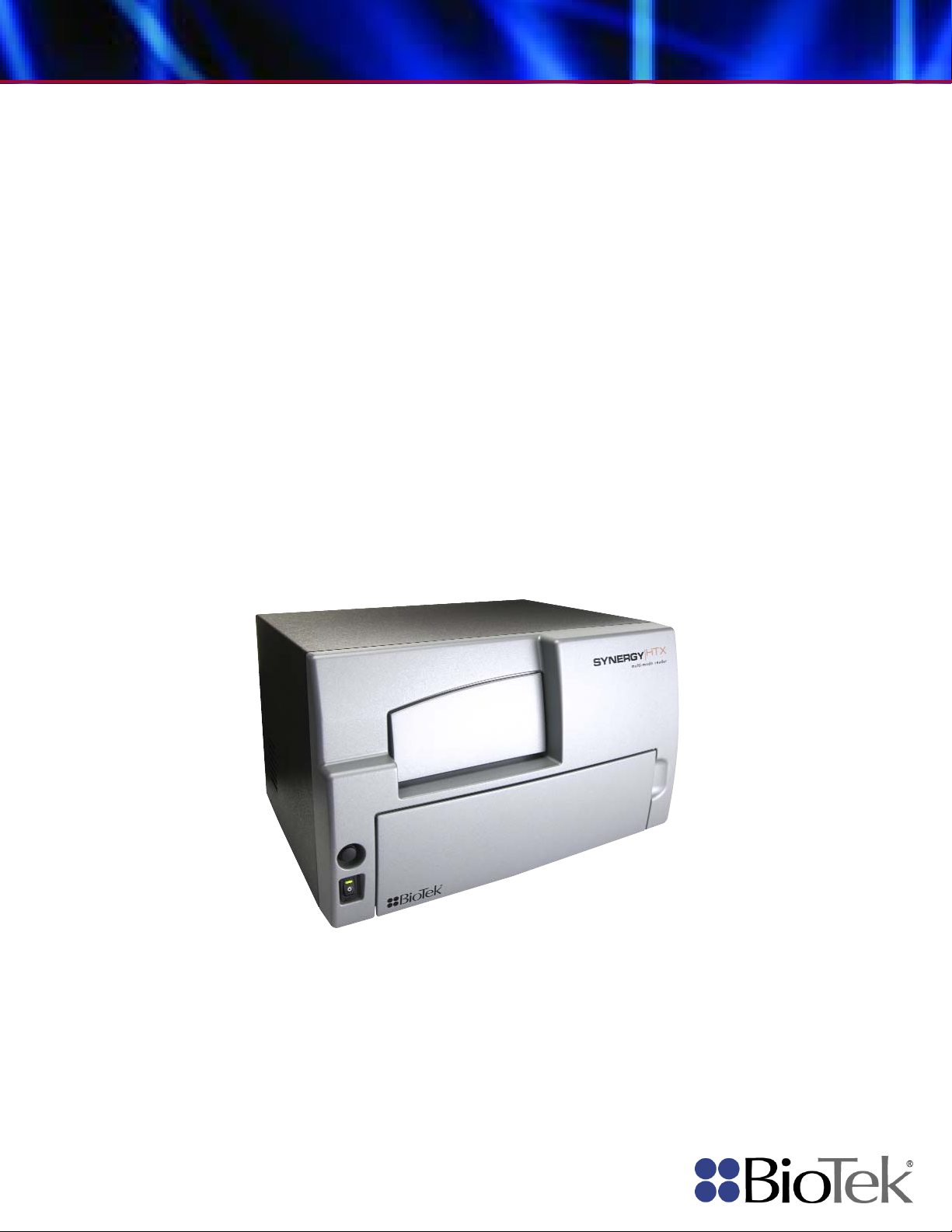
Synergy HTX
Multi-Mode Microplate Reader
Operator’s Guide
July 2014
2014
Part Number 1341000
Revision A
BioTek Instruments, Inc.
Page 4

ii | Preface
Notices
BioTek Instruments, Inc.
Highland Park, P.O. Box 998
Winooski, Vermont 05404-0998 USA
All Rights Reserved
© 2014, BioTek® Instruments, Incorporated. No part of this publication may be
reproduced, transcribed, or transmitted in any form, or by any means electronic or
mechanical, including photocopying and recording, for any purpose other than the
purchaser’s use without written permission of BioTek Instruments, Inc.
Trademarks
BioTek® is a registered trademark, and Synergy™, Gen5™, BioCell™, 4-Zone™ and
BioStack™ are trademarks of BioTek Instruments, Inc. Harta™ is a trademark of Harta
Instruments.
Microsoft
Microsoft Corporation in the United States and/or other countries.
All other trademarks are the property of their respective holders.
®
, Windows®, and Excel® are either registered trademarks or trademarks of
Restrictions and Liabilities
Information in this document is subject to change and does not represent a
commitment by BioTek Instruments, Inc. Changes made to the information in this
document will be incorporated in new editions of the publication. No responsibility is
assumed by BioTek for the use or reliability of software or equipment that is not
supplied by BioTek or its affiliated dealers.
BioTek Instruments, Inc.
Page 5

Contents
Contact Information ........................................................... v
Document Conventions ...................................................... vii
Revision History .............................................................. viii
Intended Use Statement .....................................................ix
Quality Control ..................................................................ix
Warranty and Product Registration .......................................ix
Repackaging and Shipping .................................................. x
Warnings .......................................................................... x
Hazards ............................................................................ x
Precautions ...................................................................... xii
CE Mark ......................................................................... xiii
Electromagnetic Interference and Susceptibility ................... xiv
User Safety ...................................................................... xv
Safety Symbols ............................................................... xvi
Introduction ......................................................................... 1
Synergy HTX Multi-Mode Microplate Reader ........................... 2
Package Contents .............................................................. 3
Optional Accessories .......................................................... 4
Product Support & Service .................................................. 5
Installation ........................................................................... 7
Product Registration ........................................................... 8
1: Unpack and Inspect the Reader ....................................... 8
2: Remove the Shipping Panel ........................................... 10
3: Remove the Microplate Carrier Shipping Screw ................. 11
4: Install the Fluorescence Lamp Assembly .......................... 12
Contents | iii
Customer Service and Sales ............................................ v
Global Service and Support ............................................. v
Directive 2004/108/EC: Electromagnetic Compatibility ..... xiii
Directive 2006/95/EC Low Voltage (Safety) ..................... xiii
Directive 2002/96/EC: Waste Electrical and Electronic
Equipment ................................................................. xiv
Directive 98/79/EC: In Vitro Diagnostics (if labeled for this
use) .......................................................................... xiv
USA FCC CLASS A ....................................................... xiv
Canadian Department of Communications Class A ............ xiv
Technical Assistance Center (TAC) ................................... 5
Returning Instruments for Service/Repair ......................... 5
Applications Support ...................................................... 5
Synergy HTX Operator’s Manual
Page 6

iv | Preface
Getting Started ................................................................... 31
Preventive Maintenance ..................................................... 51
5: Select an Appropriate Location ....................................... 13
6: Connect the Power Supply............................................. 14
7: Unpack and Inspect the Dispense Module ........................ 15
8: Install the Dispense Module ........................................... 18
Record Syringe Calibration Values .................................. 18
Install the Dispenser .................................................... 18
9: Connect the Host Computer .......................................... 20
10: Install Gen5 Software ................................................. 20
11: Turn on the Reader .................................................... 20
12: Establish Communication ............................................ 21
13: Set the Dispenser Calibration Values ............................. 22
14: Run a System Test ..................................................... 23
15: Test the Injector System ............................................. 24
Operational/Performance Qualification ................................ 26
Repackaging and Shipping Instructions ............................... 26
Key Components ............................................................. 32
Power Switch, Carrier Eject Button, Microplate Carrier ...... 32
Lamp Assembly and Filter Wheel Access ......................... 33
Excitation and Emission Filter Wheels ............................. 34
Installing the Time-Resolved Fluorescence Cartridge ........ 37
Configuring the System for Luminescence Measurements .. 38
The External Dispense Module ....................................... 39
Gen5 Software ................................................................ 41
Viewing/Updating the Filter and Wavelengths Tables ........ 42
Creating Protocols and Experiments ............................... 43
Controlling the Dispense Module .................................... 45
Recommendations for Optimum Performance ....................... 48
Incubation and Partial Plates ......................................... 49
Recommended Maintenance Schedule ................................. 52
Overview ................................................................... 52
Daily Cleaning for the Dispense Module .......................... 52
Recommended Maintenance Schedule ............................ 53
Warnings and Precautions ................................................. 54
Cleaning Exposed Surfaces ................................................ 55
Inspect/Clean Excitation and Emission Filters ....................... 56
Flush/Purge the Fluid Path ................................................ 57
Running a Dispense Protocol (Optional) .............................. 58
Empty/Clean the Tip Priming Trough .................................. 59
Clean the Priming Plate ..................................................... 59
Clean the Internal Components .......................................... 60
BioTek Instruments, Inc.
Page 7

Contents | v
Required Materials ....................................................... 61
Removing the Reader’s Shroud ...................................... 62
Removing the Internal Tubes and Injector Heads ............. 64
Cleaning the Internal Tubes and Injector Heads ............... 67
Cleaning the Optical Probes .......................................... 68
Cleaning the Reader’s Internal Surface ........................... 76
Reassembling the Components ...................................... 77
Performance Check ...................................................... 79
As-Needed Maintenance ..................................................... 81
Purpose .......................................................................... 82
Required Materials ........................................................... 83
Procedure for Models without Injectors ............................... 84
Routine Procedure for Models with Injectors ........................ 85
Clean Exposed Surfaces ............................................... 85
Decontaminate the Fluid Lines ....................................... 86
Rinse the Fluid Lines .................................................... 87
Clean the Internal Tubing and Injector Heads .................. 87
Clean the Tip Priming Trough and Priming Plate ............... 88
Alternate Procedure for Models with Injectors ...................... 89
Instrument Qualification .................................................... 91
Overview ........................................................................ 92
IQ/OQ/PQ ....................................................................... 92
Recommended Qualification Schedule ................................. 94
System Test .................................................................... 95
Absorbance Plate Test ..................................................... 100
Test Plate Certificates ................................................. 100
Define Absorbance Test Plate Parameters ...................... 100
Run the Absorbance Plate Test ..................................... 101
Results and Troubleshooting Tips .................................. 104
Luminescence Tests ........................................................ 105
Harta Plate Test ......................................................... 106
Gen5 Protocol Reading Parameters ............................... 107
Troubleshooting ......................................................... 109
Absorbance Liquid Tests .................................................. 109
Absorbance Liquid Test 1 ............................................. 110
Absorbance Liquid Test 2 ............................................. 112
Absorbance Liquid Test 3 (optional) .............................. 114
Fluorescence Tests .......................................................... 116
Required Materials ...................................................... 117
Test Solutions ............................................................ 118
Procedure ................................................................. 119
Results Analysis ......................................................... 119
Synergy HTX Operator’s Manual
Page 8

vi | Preface
Specifications ................................................................... 143
Error Codes ...................................................................... 151
Troubleshooting ......................................................... 120
Pipette Map ............................................................... 121
Gen5 Protocol Reading Parameters ............................... 122
Fluorescence Tests Using Methylumbelliferone ................ 126
Dispense Module Tests .................................................... 131
Required Materials ...................................................... 132
Alternate Test Solutions .............................................. 133
Procedure for Models with Absorbance Capabilities .......... 133
Procedure for Models without Absorbance Capabilities ..... 135
Results Analysis ......................................................... 136
Gen5 Test Protocols for Models with Absorbance Capabilities137
Gen5 Test Protocols for Models without Absorbance
Capabilities ............................................................... 139
Create the Dispense Protocols ...................................... 139
General Specifications ..................................................... 144
Absorbance Specifications ................................................ 145
Fluorescence Specifications .............................................. 147
Luminescence Specifications ............................................. 148
Models with Injectors ...................................................... 149
Error Codes Overview ...................................................... 152
Contact Info: BioTek Service/TAC ................................. 152
Error Codes ................................................................... 153
BioTek Instruments, Inc.
Page 9
Contact Information | v
Mailing Address:
Winooski, VT 05404
Room 304, Tower D
Phone: (800) 242-4685
Phone: +86 (10) 85865569
Email: TAC@biotek.com
Website: www.biotek.com
Email: infochina@biotek.com
Website: www.biotekchina.com.cn
Kocherwaldstrasse 34 D-74177
Germany
50 avenue d'Alsace
France
Phone: +49 (0) 71369680
Fax: +49 (0) 7136968111
Phone: +33 (3) 89206329
Fax: +33 (3) 89204379
Email: info@biotek.de
Website: www.biotek.de
Email: info@biotek.fr
Website: www.biotek.fr
BioTek India
BioTek Singapore
Unit 223, Linkway Estate
Mumbai 400064
20 Science Park Road #01-08A
Singapore 117674
Contact Information
Customer Service and Sales
Internet: www.biotek.com
Phone: 888-451-5171 (toll-free in the U.S.)
802-655-4740 (outside the U.S.)
Fax: 802-655-7941
Email: customercare@biotek.com
Global Service and Support
BioTek instrument service and repair is available worldwide at one of BioTek's
International Service Centers and in the field at your location. For technical assistance,
contact the Technical Assistance Center (TAC) at BioTek World Headquarters US. To
arrange for service or repair of your instrument, contact the office nearest you.
BioTek World Headquarters US BioTek China
PO Box 998, Highland Park
Winooski, VT 05404-0998
United States
Service Shipping Address:
15 Tigan Street
Outside US: (802) 655-4740
Fax: (802) 654-0638
BioTek Germany Service Center &
European Coordination Center
Bad Friedrichshall
Ocean International Center
62 Middle 4th East Ring Road
Chaoyang District
Beijing 100025
P.R. China
Fax: +86 (10) 85861829
BioTek Instruments SAS
Bureau de liaison France
68025 Colmar Cedex
New Link Road, Malad West
Synergy HTX Operator’s Manual
Teletech Park
Page 10
vi | Preface
India
Phone: +91 (22) 28789966
Fax: +91 (22) 28759944
Phone: +65 65922100
Fax: +65 67772611
Email: biotek@biotek.in
Website: www.biotek.in
Email: singapore@biotek.com
Website: www.biotek.com
3F, Gyungnam building, 830-48
Seoul, South Korea (135-936)
Zentrum Fanhöfli 8
Switzerland
Phone: +82 (0) 2-562-4740
Fax: +82 (0) 2-562-4750
Phone: +41 (41) 2504060
Fax: +41 (41) 2505064
Email: korea@biotek.com
Website: www.biotekinstruments.co.kr
Email: info@biotek.ch
Website: www.biotek.ch
6 Bull Street
United Kingdom
Phone: +44 (1767) 262000
Fax: +44 (1767) 262330
Email: info@biotek.uk.com
Website: www.biotek.uk.com
BioTek South Korea BioTek Switzerland
Yeoksam-dong, Gangnam-gu
BioTek United Kingdom (UK)
Potton, Bedfordshire SG19 2NR
6014 Luzern
BioTek Instruments, Inc.
Page 11
Document Conventions
This icon calls attention to important safety notes.
Document Conventions | vii
Warning!
Caution
Note:
italic
A Warning indicates the potential for bodily harm and
tells you how to avoid the problem.
A Caution indicates potential damage to the instrument
and tells you how to avoid the problem.
Bold text is primarily used for emphasis.
Topics that apply only to specific Synergy HTX models are
preceded by a notice in italics, for example: Applies only to
Synergy HTX models with injectors.
This icon calls attention to important information.
Synergy HTX Operator’s Manual
Page 12

viii | Preface
Rev
Date
Changes
Revision History
A 7/2014 Initial release
BioTek Instruments, Inc.
Page 13

Intended Use Statement
• The Synergy HTX is a single-channel absorbance, fluorescence, and luminescence
microplate reader that uses a dual-optics design to perform measurements of
samples in a microplate format. The performance characteristics of the data
reduction software have not been established with any laboratory diagnostic assay.
The user must evaluate this instrument and Gen5 software in conjunction with
their specific assay(s). This evaluation must include the confirmation that
performance characteristics for the specific assay(s) are met.
• If the instrument has an “IVD” label, it may be used for clinical and non-clinical
purposes, including research and development. If there is no such label, the
instrument may be used only for research and development or other non-clinical
purposes.
Quality Control
Intended Use Statement | ix
It is considered good laboratory practice to run laboratory samples according to
instructions and specific recommendations included in the assay package insert for the test
to be conducted. Failure to conduct Quality Control checks could result in erroneous test
data.
Warranty and Product Registration
Take a moment to review the Warranty information that shipped with your product.
Please also register your product with BioTek to ensure that you receive important
information and updates about the product(s) you have purchased. You can register online
through the Customer Resource Center at www.biotek.com or by calling 888/451-5171 or
802/655-4740.
Synergy HTX Operator’s Manual
Page 14
x | Preface
Operate the instrument on a level, stable surface away from excessive humidity.
removing its top case.
receptacle may produce electrical shock and fire hazards.
cord directly to an appropriate receptacle with a functional ground.
Repackaging and Shipping
If you need to ship the instrument to BioTek for service or repair,
contact BioTek for a service authorization number, and be sure to
use the original packing materials. Other forms of commercially
available packaging are not recommended and can void the
warranty. If the original packing materials have been damaged or
lost, contact BioTek for replacement packing.
Warnings
Bright sunlight or strong incandescent light can reduce the linear performance range
of the instrument.
Measurement values may be affected by extraneous particles (such as dust) in the
microplate wells. A clean work area is necessary to ensure accurate readings.
When operated in a safe environment according to the instructions in this document,
there are no known hazards associated with the instrument. However, the operator
should be aware of certain situations that could result in serious injury; these may
vary depending on the instrument model. See
Hazards and Precautions.
Hazards
The following hazard warnings are provided to help avoid injury:
Warning! Internal Voltage. Always turn off the power switch and unplug
the power supply before cleaning the outer surface of the instrument or
Warning! Power Rating. The instrument’s power supply or power cord
must be connected to a power receptacle that provides voltage and current
within the specified rating for the system. Use of an incompatible power
Warning! Electrical Grounding. Never use a plug adapter to connect
primary power to the external power supply. Use of an adapter disconnects
the utility ground, creating a severe shock hazard. Always connect the power
BioTek Instruments, Inc.
Page 15
Hazards | xi
specifications shall be used with the instrument.
people when lifting and carrying the instrument.
carrier path and cause the instrument to produce an error.
instrument if internal components have been exposed to fluid.
hazardous condition.
.
thoroughly analyzed by the operator.
chemically resistant rubber gloves and apron.
attempting replacement.
when the instrument is operating.
Warning! Service.
Only qualified technical personnel should perform
service procedures on internal components.
Warning! Accessories. Only accessories that meet the manufacturer’s
Warning! The instrument weighs approximately 38 pounds (17 kg). Use two
Warning! Lubricants. Do not apply lubricants to the microplate carrier or
carrier track. Lubricant on the carrier mechanism or components in the carrier
compartment will attract dust and other particles, which may obstruct the
Warning! Liquids. Avoid spilling liquids on the instrument; fluid seepage
into internal components creates a potential for shock hazard or instrument
damage. If a spill occurs while a program is running, abort the program and
turn the instrument off. Wipe up all spills immediately. Do not operate the
Warning! Unspecified Use. Failure to operate this equipment according to
the guidelines and safeguards specified in this manual could result in a
Warning! Software Quality Control. The operator must follow the
manufacturer’s assay package insert when modifying software parameters
and establishing reading, washing, or dispensing methods.
conduct quality control checks could result in erroneous test data
Failure to
Warning! Reader Data Reduction Protocol. No limits are applied to the
raw absorbance data. All information exported via computer control must be
Warning! Potential Biohazards. Some assays or specimens may pose a
biohazard. Adequate safety precautions should be taken as outlined in the
assay’s package insert. This hazard is noted by the symbol shown here.
Always wear safety glasses and appropriate protective equipment, such as
Warning! Hot Surface. The lamp assembly is hot when the instrument is
turned on. Turn off the reader and allow the lamp to cool down before
Warning! Pinch Hazard. Some areas of the dispense module can present
pinch hazards when the instrument is operating. The module is marked with
one of the symbols shown here. Keep hands/fingers clear of these areas
Synergy HTX Operator’s Manual
Page 16

xii | Preface
and potentially impair instrument performance or cause damage to the instrument.
limits are broader.
and thoroughly wipe all surfaces.
Operate this power supply within the range of line voltages listed on it.
“on waste electrical and electronic equipment (WEEE),” or local ordinances.
the warranty.
shipment.
intended.
RF sources), because these may interfere with the proper operation.
Precautions
The following precautions are provided to help avoid damage to the instrument:
Caution: Service. The instrument should be serviced by BioTek authorized service
personnel. Only qualified technical personnel should perform troubleshooting and
service procedures on internal components.
Caution: Spare Parts. Only approved spare parts should be used for maintenance.
The use of unapproved spare parts and accessories may result in a loss of warranty
Caution: Environmental Conditions. Do not expose the instrument to
temperature extremes. For proper operation, ambient temperatures should remain
within the range listed in the
affected if temperatures fluctuate above or below this range. Storage temperature
Caution: Sodium Hypochlorite. Do not expose any part of the instrument to the
recommended diluted sodium hypochlorite solution (bleach) for more than 20
minutes. Prolonged contact may damage the instrument surfaces. Be certain to rinse
Specifications section. Performance may be adversely
Caution: Power Supply. Only use the power supply shipped with the instrument.
Caution: Disposal. Dispose of the instrument according to Directive 2002/96/EC,
Caution: Warranty. Failure to follow preventive maintenance protocols may void
Caution: Shipping Hardware. All shipping hardware must be removed before
operating the instrument and reinstalled before repackaging the instrument for
Caution: Electromagnetic Environment. Per IEC 61326-2-6 it is the user’s
responsibility to ensure that a compatible electromagnetic environment for this
instrument is provided and maintained in order that the device will perform as
Caution: Electromagnetic Compatibility. Do not use this device in close
proximity to sources of strong electromagnetic radiation (e.g., unshielded intentional
BioTek Instruments, Inc.
Page 17
CE Mark
Based on the testing described below and information contained
herein, this instrument bears the CE mark
See the Declaration of Conformity for more information.
Directive 2004/108/EC: Electromagnetic Compatibility
Emissions—Class A
The system has been type-tested by an independent, accredited testing laboratory
and found to meet the requirements of EN 61326-1: Class A for Radiated Emissions
and Line Conducted Emissions. Verification of compliance was conducted to the
limits and methods of EN 55011 – (CISPR 11) Class A. In a domestic environment it
may cause radio interference, in which case you may need to mitigate the
interference.
CE Mark | xiii
Immunity
The system has been type-tested by an independent, accredited testing laboratory
and found to meet the requirements of EN 61326-1 and EN 61326-2-6 for Immunity.
Verification of compliance was conducted to the limits and methods of the
following:
EN 61000-4-2, Electrostatic Discharge
EN 61000-4-3, Radiated EM Fields
EN 61000-4-4, Electrical Fast Transient/Burst
EN 61000-4-5, Surge Immunity
EN 61000-4-6, Conducted Disturbances from RFI
EN 61000-4-11, Voltage Dips, Short Interruptions and Variations
Directive 2006/95/EC Low Voltage (Safety)
The system has been type-tested by an independent testing laboratory and was found
to meet the requirements of this Directive. Verification of compliance was conducted to
the limits and methods of the following:
EN 61010-1. “Safety requirement for electrical equipment for measurement, control and
laboratory use. Part 1, General requirements.”
EN 61010-2-081, “Particular requirements for automatic and semi-automatic laboratory
equipment for analysis and other purposes.”
Synergy HTX Operator’s Manual
Page 18

xiv | Preface
EN 61010-2-010, “Particular requirements for laboratory equipment for the heating of
materials.”
Directive 2002/96/EC: Waste Electrical and Electronic Equipment
Disposal Notice: Dispose of the instrument according to Directive 2002/96/EC, “on
waste electrical and electronic equipment (WEEE)” or local ordinances.
Directive 98/79/EC: In Vitro Diagnostics (if labeled for this use)
• Product registration with competent authorities.
• Traceability to the U.S. National Institute of Standards and Technology (NIST).
• EN 61010-2-101, “Particular requirements for in vitro diagnostic (IVD) medical
equipment.”
Electromagnetic Interference and Susceptibility
USA FCC CLASS A
RADIO AND TELEVISION INTERFERENCE
Note:
This equipment has been tested and found to comply with the limits for a
Class A digital device, pursuant to Part 15 of the FCC Rules. These limits are
designed to provide reasonable protection against harmful interference when the
equipment is operated in a commercial environment. Like all similar equipment,
this equipment generates, uses, and can radiate radio frequency energy and, if not
installed and used in accordance with the instruction manual, may cause harmful
interference to radio communications. Operation of this equipment in a residential
area is likely to cause interference, in which case users will be required to correct
the interference at their own expense.
In order to maintain compliance with FCC regulations, shielded cables must be
used with this equipment. Operation with non-approved equipment or unshielded
cables is likely to result in interference to radio and television reception.
Canadian Department of Communications Class A
This digital apparatus does not exceed Class A limits for radio emissions from
digital apparatus set out in the Radio Interference Regulations of the Canadian
Department of Communications.
Le present appareil numerique n'emet pas de bruits radioelectriques depassant les
limites applicables aux appareils numerique de la Class A prescrites dans le
Reglement sur le brouillage radioelectrique edicte par le ministere des
Communications du Canada.
BioTek Instruments, Inc.
Page 19

User Safety | xv
User Safety
This device has been type-tested by an independent laboratory and found to meet the
requirements of the following:
• Underwriters Laboratories UL 61010-1, “Safety requirements for electrical
equipment for measurement, control and laboratory use; Part 1: General
requirements.”
• Canadian Standards Association CAN/CSA C22.2 No. 61010-1, “Safety
requirements for electrical equipment for measurement, control and laboratory
use; Part 1: General requirements.”
• EN 61010 Standards, see
CE Mark starting on page xiii.
Synergy HTX Operator’s Manual
Page 20
xvi | Preface
Safety Symbols
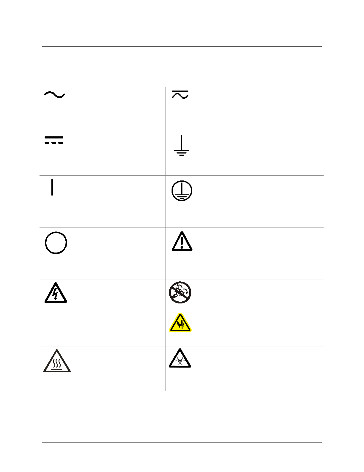
Some of these symbols appear on the instrument or accessories:
Alternating current
Courant alternatif
Wechselstrom
Corriente alterna
Corrente alternata
Both direct and alternating current
Courant continu et courant alternatif
Gleich - und Wechselstrom
Corriente continua y corriente alterna
Corrente continua e corrente alternata
Direct current
Courant continu
Gleichstrom
Corriente continua
Corrente continua
On (Supply)
Marche (alimentation)
Ein (Verbindung mit dem
Netz)
Conectado
Chiuso
Off (Supply)
Arrêt (alimentation)
Aus (Trennung vom Netz)
Desconectado
Aperto (sconnessione dalla
rete di alimentazione)
Warning, risk of electric shock
Attention, risque de choc
électrique
Gefährliche elektrische schlag
Precaución, riesgo de
sacudida eléctrica
Attenzione, rischio di scossa
elettrica
Earth ground terminal
Borne de terre
Erde (Betriebserde)
Borne de tierra
Terra (di funzionamento)
Protective conductor terminal
Borne de terre de protection
Schutzleiteranschluss
Borne de tierra de protección
Terra di protezione
Caution (refer to accompanying documents)
Attention (voir documents d’accompanement)
Achtung siehe Begleitpapiere
Atención (vease los documentos incluidos)
Attenzione, consultare la doc annessa
Warning, risk of crushing or pinching
Attention, risque d’écrasement et pincement
Warnen, Gefahr des Zerquetschens und
Klemmen
Precaución, riesgo del machacamiento y
sejeción
Attenzione, rischio di schiacciare ed
intrappolarsi
Warning, hot surface
Attention, surface chaude
Warnen, heiße Oberfläche
Precaución, superficie caliente
Attenzione, superficie calda
BioTek Instruments, Inc.
Warning, potential biohazards
Attention, risques biologiques potentiels
Warnung! Moegliche biologische Giftstoffe
Atención, riesgos biológicos
Attenzione, rischio biologico
Page 21

Safety Symbols | xvii
In vitro diagnostic medical
device
Dispositif médical de
diagnostic in vitro
Medizinisches In-VitroDiagnostikum
Dispositivo médico de
diagnóstico in vitro
Dispositivo medico
diagnostico in vitro
Separate collection for electrical and
electronic equipment
Les équipements électriques et
électroniques font l’objet d’une collecte
sélective
Getrennte Sammlung von Elektro- und
Elektronikgeräten
Recogida selectiva de aparatos eléctricos y
electrónicos
Raccolta separata delle apparecchiature
elettriche ed elettroniche
Consult instructions for use
Consulter la notice d’emploi
Gebrauchsanweisung beachten
Consultar las instrucciones de
uso
Consultare le istruzioni per
uso
Synergy HTX Operator’s Manual
Page 22

xviii | Preface
BioTek Instruments, Inc.
Page 23

Chapter 1
Introduction
This chapter introduces the Synergy HTX, describes its key
features, lists its package contents, and provides contact
information for technical assistance.
Synergy HTX Multi-Mode Microplate Reader ............................... 2
Package Contents ................................................................... 3
Optional Accessories ............................................................... 4
Product Support & Service ....................................................... 5
Technical Assistance Center (TAC) ........................................ 5
Returning Instruments for Service/Repair .............................. 5
Applications Support .......................................................... 5
Page 24

2 | Chapter 1: Introduction
Synergy HTX Multi-Mode Microplate Reader
The Synergy HTX is a single-channel microplate reader available with absorbance,
fluorescence, and luminescence detection. It is computer-controlled using BioTek’s Gen5
software for all operations including data reduction and analysis. Synergy HTX is robot
accessible and compatible with BioTek’s BioStack Microplate Stacker.
When making fluorescence determinations, the Synergy HTX uses a tungsten quartz
halogen lamp with interference filters for wavelength specificity in conjunction with a
photomultiplier (PMT) tube detector. The Synergy HTX has both top and bottom probes
for fluorescence measurements. The top probe can be adjusted vertically for the correct
reading height, via Gen5’s Read Height reading parameter (see
Started
Luminescence is measured by the low-noise PMT detector through an empty filter position
in the Emission filter wheel. A filter can also be left in place if light filtering is necessary.
Absorbance measurements are made by switching to a xenon flash lamp and a
monochromator for wavelength selection. The use of a xenon flash lamp allows for both
UV and visible light absorbance measurements. The monochromator provides wavelength
selection from 200 to 999 nm in 1-nm increments.
).
Chapter 3, Getting
The Synergy HTX has a 4-Zone temperature control from 4°C over ambient to 50°C,
controlled via a software-adjustable gradient. Internal plate shaking, with both linear and
orbital modes, is supported to ensure that reagents are properly mixed prior to reading.
Both Synergy HTX models support the reading of 6-, 12-, 24-, 48-, 96-, and 384-well
microplates with standard 128 x 86 mm geometry, as well as the BioTek Take3 and Take3
Trio Micro-Volume Plates. Absorbance mode reads plates up to 0.8" (20.3 mm) in height;
fluorescence mode reads plates up to 1.25" (31.75 mm). Polymerase Chain Reaction (PCR)
tubes up to 1.25" (31.75 mm) are also readable with the use of existing adapter plates.
For models with time-resolved fluorescence (TRF) capability, the TRF option allows
measurements by using the xenon flash light source in conjunction with the PMT
measurement detector. A special cartridge installed in the Excitation filter wheel location is
required.
Models with injectors support dual-reagent dispensing to 6-, 12-, 24-, 48-, 96-, and 384-well
microplates with standard 128 x 86 mm geometry. An external dispense module pumps
fluid from the supply bottles to the two injectors located inside the instrument. Both
injectors are positioned directly above the bottom probe, and fluid is injected into one well
at a time.
BioTek Instruments, Inc.
Page 25

Package Contents | 3
Item
Part #
Package Contents
Part numbers and package contents are subject to change. Contact
BioTek Customer Care with any questions.
Synergy HTX Operator’s Manual 1341000
Power supply 76061
Power cord set (specific to installation environment):
Europe (Schuko)
USA/International
United Kingdom
Australia/New Zealand
RS-232 serial cable 75034
USB cable
with USB Driver Software
Wrench 7772028
Fluorescence lamp assembly* (Note: The replacement lamp assembly is
PN 7080500)
Filter “plugs” (2) (also referred to as “dummy filters” or “blanks”)* 7082073
Plastic storage bag and fastener strips —
Time-Resolved Fluorescence cartridge assembly (“T” models only) 7090523
Models with injectors, an external dispense module (packed
separately), with the following accessories:
Outlet tubes (2, plus 2 spare) from dispense module to instrument
Inlet tubes (2) from supply bottles to syringe drives
250 µl syringes (2)
Syringe thumbscrews (2)
Priming plate
Injector tip priming trough
Dispense module communication cable
Dispense module front cover
Supply bottles (2, 30 mL)
Supply bottle holder assemblies (2)
Injector tip cleaning stylus and plastic storage bag
* If applicable to your reader model.
7090204
7080501
7082120
7082121
7083000
7132158
1342017
7082137
7122609
7090564
2872304
75010
75011
75012
75013
75108
19511
75107
Synergy HTX Operator’s Manual
Page 26

4 | Chapter 1: Introduction
Item
Part #
Optional Accessories
Accessory availability and part numbers are subject to change. Contact
BioTek Customer Care with questions or visit www.biotek.com and use
the Accessories search tool.
7-filter Absorbance Test Plate
Fluorescence Test Plate
Product Qualification (IQ-OQ-PQ) package
PCR Tube Adapter Plates
Terasaki Adapter Plate
Take3 Micro-Volume Plate
Take3 Trio Micro-Volume Plate
BioCell Quartz Vessel and Adapter Plate
Additional Fluorescence Filters; contact BioTek for part numbers and availability
The Synergy HTX is compatible with the BioStack Microplate Stacker. Contact BioTek or
visit our website to learn more.
7260522
7092092
1340508
6002072 and
6002076
7330531
TAKE3
Take3Trio
7272051/7270512
For Use with Liquid Tests (see Chapter 5) Part #
Absorbance Liquid Test Solutions:
BioTek Wetting Agent Solution
BioTek QC Check Solution #1
25 mL
125 mL
Dispense Module Liquid Test Solution:
BioTek Green Test Dye
BioTek Blue Test Dye
BioTek QC (Yellow) Test Dye
Individual Fluorescence Liquid Test Solutions:
Sodium Fluorescein Powder
Liquid Test Kit using Sodium Fluorescein
Liquid Test Kit using Methylumbelliferone (“MUB”)
7773002
7120779
7120782
7773003
7773001
7120782
98155
7160013
7160012
BioTek Instruments, Inc.
Page 27

Product Support & Service
Technical Assistance Center (TAC)
If your instrument(s) or software fails to function properly, if you have questions about
how to use or maintain our products, or if you need to send an instrument to BioTek
for service or repair, please contact our Technical Assistance Center. BioTek’s “TAC” is
open from 8:30 AM to 5:30 PM (EST), Monday through Friday, excluding standard U.S.
holidays. You can send a fax or an e-mail any time. You can also request technical
assistance via our website:
Phone: (800) 242-4685 or Fax: (802) 654-0638 E-Mail: tac@biotek.com
(802) 655-4740
Please be prepared to provide the following information:
• Your name and company information, along with a daytime phone or fax
number, and/or an e-mail address
• The product name, model, and serial number
www.biotek.com.
Product Support & Service | 5
Web: www.biotek.com
• The onboard software part number and version (available through Gen5 at
System > Instrument Configuration > Get Basecode Information)
• Gen5 software version information (
Help > About Gen5)
• For troubleshooting assistance or instruments needing repair, the specific steps
that produce your problem and any error codes displayed in Gen5
(see also
Appendix C, Error Codes)
• A text file of the diagnostic history of the instrument (available via Gen5 by
selecting
file and clicking
System > Diagnostics > History, then selecting the appropriate
Export)
Returning Instruments for Service/Repair
If you need to return an instrument to BioTek for service or repair, please contact the
TAC for a service authorization number before shipping the instrument. Repackage the
instrument properly (see
Chapter 2, Installation), write the number on the shipping
box, and ship to BioTek.
Applications Support
BioTek’s fully equipped Application Laboratory provides our on-staff scientists with
the means to assist you with the integration of our instrumentation and software with
your unique scientific applications. If you are having difficulty with optimizing
fluorescence sensitivity or integrating a unique data reduction transformation, or you
are just looking for a recommendation on an appropriate fluorophore, contact us.
Phone: (888) 451-5171 E-Mail: applications@biotek.com
Synergy HTX Operator’s Manual
Page 28

6 | Chapter 1: Introduction
BioTek Instruments, Inc.
Page 29

Chapter 2
Installation
This chapter includes instructions for unpacking and setting up
the Synergy HTX and, if applicable, the external dispense module.
Instructions are also included for repackaging the reader and
dispense module for shipment.
Product Registration ............................................................... 8
1: Unpack and Inspect the Reader ............................................ 8
2: Remove the Shipping Panel ............................................... 10
3: Remove the Microplate Carrier Shipping Screw ..................... 11
4: Install the Fluorescence Lamp Assembly .............................. 12
5: Select an Appropriate Location ........................................... 13
6: Connect the Power Supply ................................................. 14
7: Unpack and Inspect the Dispense Module ............................ 15
8: Install the Dispense Module ............................................... 18
9: Connect the Host Computer ............................................... 20
10: Install Gen5 Software ...................................................... 20
11: Turn on the Reader ......................................................... 20
12: Establish Communication ................................................. 21
13: Set the Dispenser Calibration Values ................................. 22
14: Run a System Test ......................................................... 23
15: Test the Injector System ................................................. 24
Operational/Performance Qualification ..................................... 26
Repackaging and Shipping Instructions ................................... 26
Page 30

8 | Chapter 2: Installation
Product Registration
Please register your product with BioTek to ensure that you receive important information
and updates about the products you have purchased. Contact the Customer Resource
Center (CRC) at www.biotek.com or by calling 888-451-5171 or 802-655-4740.
1: Unpack and Inspect the Reader
Important! Save all packaging materials. If you need to ship the
reader to BioTek for repair or replacement, you must use the
original materials. Using other forms of commercially available
packaging, or failing to follow the repackaging instructions, may
void your warranty. Improper packaging that results in damage
to the instrument may lead to additional charges.
During the unpacking process, inspect the packaging, reader, and
accessories for shipping damage. If the reader is damaged, notify
the carrier and your BioTek representative. Keep the shipping
boxes and the packaging materials for the carrier’s inspection.
BioTek will arrange for repair or replacement of your reader
immediately.
1. Open the outer shipping box. Remove the foam blocks to access the inner box.
2. Carefully open the inner shipping box. Remove the accessories box and set it aside.
Remove the vertical supports.
Warning! The instrument weighs approximately 38 pounds (17 kg).
Use two people when lifting and carrying the instrument.
3. The Synergy HTX is attached to a shipping panel that has two handles for lifting.
Locate and grasp the handles. Carefully lift the reader out of the box and place it on
a level surface. Remove the protective plastic bag.
4. Place all packing material back into the shipping box for reuse if the reader needs to
be shipped again.
See Package Contents in Chapter 1 for assistance with identifying
the contents of the accessories box.
BioTek Instruments, Inc.
Page 31

1: Unpack and Inspect the Reader | 9
accessories box
Figure 1: Unpacking the reader
Synergy HTX Operator’s Manual
Page 32

10 | Chapter 2: Installation
2: Remove the Shipping Panel
1. Carefully tip the reader onto its back.
2. Using a screwdriver, remove the four screws and washers attaching the shipping
panel to the bottom of the reader. See
3. Carefully set the reader upright.
4. Locate the supplied plastic tool storage pocket. Place the screws and washers inside
the bag. Use the supplied fastener strips to attach the pocket to the back of the reader
for storage. Do not block any air vents. See Figure 2 on the next page.
5. Place the panel back into the inner shipping box for storage.
Important: Reattach the shipping panel before
repackaging the Synergy HTX for shipment.
Figure 2 on the next page.
BioTek Instruments, Inc.
Page 33

3: Remove the Microplate Carrier Shipping Bolt | 11
Figure 2: Removing the shipping panel
3: Remove the Microplate Carrier Shipping Bolt
Important: Remove the microplate carrier shipping bolt
1. Pull down the microplate loading door on the front of the reader.
2. Using the supplied wrench, remove the carrier shipping bolt with its o-ring and
warning tag.
Synergy HTX Operator’s Manual
before turning on the Synergy HTX.
Page 34

12 | Chapter 2: Installation
3. Store the wrench, bolt, o-ring, and tag in a safe place, in case you need to ship the
instrument back to BioTek.
shipping bolt
o-ring
shipping bolt
warning tag
Figure 3: Removing the microplate carrier shipping bolt
Important: Replace the microplate carrier shipping bolt
before repackaging the Synergy HTX for shipment. Please
contact BioTek if you have misplaced the bolt (PN
1342008) and/or its o-ring (PN 49259).
4: Install the Fluorescence Lamp Assembly
Applies only to Synergy HTX models with fluorescence capability.
Important: Do not touch the glass lenses! Fingerprints on
the condenser lens or heat absorber may negatively affect
performance.
BioTek Instruments, Inc.
Page 35

5: Select an Appropriate Location | 13
Warning! The fluorescence lamp assembly is hot when the
instrument is powered on. If the instrument is on, turn it off and
allow the lamp to cool down before attempting to replace it.
1. Locate the lamp assembly in the accessories box. The lamp is attached to a metal
bracket that also holds a condenser lens and a heat absorber. Two cables are attached
to the back of the lamp.
2. Open the hinged door on the front of the reader by pressing on its lower left and
right corners. The lamp compartment is on the far left.
3. Orient the lamp assembly as shown below. Slide the assembly all the way into the
compartment.
4. Plug the lamp cables into the power source located to the right of the lamp. Either
cable can be plugged into either socket.
5. Close the hinged door.
Figure 4: Installing the fluorescence lamp assembly (replacement lamp PN 7080500)
5: Select an Appropriate Location
Install the Synergy HTX on a level surface in an area where ambient temperatures between
18ºC (64ºF) and 40ºC (104ºF) can be maintained.
The reader is sensitive to extreme environmental conditions. Avoid the following:
Synergy HTX Operator’s Manual
Page 36

14 | Chapter 2: Installation
• Excessive humidity: Condensation directly on the sensitive electronic circuits
can cause the reader to fail internal self-checks. The specified relative humidity
range for this reader is from 10% to 85% (non-condensing).
Excessive ambient light: Bright sunlight or strong incandescent light may affect
•
the reader’s optics and readings, reducing its linear performance range.
Dust: Readings may be affected by extraneous particles (such as dust) in the
•
microplate wells. A clean work area is necessary to ensure accurate readings.
If you will be installing BioTek’s BioStack Microplate Stacker for
operation with the Synergy HTX, you may wish to seat the BioStack
and the reader in their aligning plates at this time. Refer to the
BioStack Operator’s Manual for more information.
6: Connect the Power Supply
Warning! Power Rating. The power supply must be
connected to a power receptacle that provides voltage and
current within the specified rating for the system. Use of an
incompatible power receptacle may produce electrical shock
and fire hazards.
Warning! Electrical Grounding. Never use a plug adapter to
connect primary power to the external power supply. Use of an
adapter disconnects the utility ground, creating a severe shock
hazard. Always connect the power cord directly to an
appropriate receptacle with a functional ground.
1. Plug the rounded end of the power supply’s cord into the power inlet on the rear of
the reader.
2. Connect the power cord to the external power supply.
3. Plug the power cord into an appropriate power receptacle.
BioTek Instruments, Inc.
Page 37

7: Unpack and Inspect the Dispense Module | 15
7: Unpack and Inspect the Dispense Module
Applies only to Synergy HTX models with injectors.
Important! Save all packaging materials. If you need to ship
the dispense module to BioTek for repair or replacement, you
must use the original materials. Using other forms of
commercially available packaging, or failing to follow the
repackaging instructions, may void your warranty.
During the unpacking process, inspect the packaging, module,
and accessories for shipping damage. If the reader is damaged,
notify the carrier and your BioTek representative. Keep the
shipping boxes and the packaging materials for the carrier’s
inspection. BioTek will arrange for repair or replacement of
your reader immediately.
1. Open the outer shipping box. Remove the foam cap, inner shipping box, and
accessories box.
Figure 5: Unpacking the dispense module’s outer shipping box
Synergy HTX Operator’s Manual
Page 38

16 | Chapter 2: Installation
Shipping insert
Inner
shipping box
Dispense
module
module
box
2. Using no sharp tools, open the box containing the dispense module. Remove the
two reagent bottle holders and the cardboard shipping insert. Lift out the module
and place it on a level surface.
Reagent
bottle holders
(2)
Cardboard insert
Dispense
Inner shipping
Figure 6: Unpacking the dispense module’s inner shipping box
3. Open the accessories box. Remove and identify its contents (see
next page):
• 2 inlet tubes, packaged in plastic cylinders
• 4 outlet tubes, packaged in plastic bags
• 2 syringes, packaged in boxes
• 1 priming plate
• 2 reagent bottles
• 1 injector tip priming trough (small, plastic cup)
• 1 plastic tool storage bag with fastener strips
• 2 metal thumbscrews
• 1 stylus (wire) packaged in a small plastic cylinder
Figure 7 on the
• 1 dispense module cover
• 1 dispense module cable
BioTek Instruments, Inc.
Page 39

7: Unpack and Inspect the Dispense Module | 17
end cap (with
Top foam
end cap
Inlet tubes (2)
Outlet tubes (4)
Dispense module
cable
Dispense
module cover
Syringes (2)
Accessories
box
Bottom foam
cutouts)
Figure 7: Unpacking the dispense module’s accessories
Synergy HTX Operator’s Manual
Page 40

18 | Chapter 2: Installation
8: Install the Dispense Module
Applies only to Synergy HTX models with injectors.
Record Syringe Calibration Values
If applicable, perform these steps to record calibration information and then install the
dispenser.
1. Record the syringe calibration values that were set at BioTek:
a. On the back panel of the dispenser box, locate the two labels that show
the six target volumes (200, 80, 40, 20, 10, and 5) and the six
corresponding calibration values.
b. Record the 12 calibration values in the IQ Checklist.
Install the Dispenser
1. Place the module to the left side or on top of the reader.
2. On the rear panel of the reader, identify the SYRINGE 1 and SYRINGE 2 tubing
ports. Remove the nylon screws from both ports and set them aside.
3. Open two of the plastic bag containing the injector tubes and tips. Remove the
clear plastic shrouds from the tubes. Put the other two bags in a safe place; they
are spares.
4. Remove the two inlet tubes from their plastic canisters.
5. Identify the two syringe valves on the dispense module. Each is labeled with a
left-pointing arrow.
When installing the inlet and outlet tubes, do not use any tools.
Finger-tighten only!
6. Screw the fitting of one inlet tube into the right side of the Syringe 1 valve.
7. Screw one end of one outlet tube into the left side of the Syringe 1 valve.
8. Screw the other end of the outlet tube into the SYRINGE 1 port on the rear of
the reader.
9. Repeat these steps to attach the inlet and outlet tubing for Syringe 2.
It is critical that the tubing is installed in the correct ports. Otherwise,
injected fluid may miss the intended well.
10. Remove the two syringes from their protective boxes. They are identical and
interchangeable. Each syringe should already be assembled in one piece, but if
for some reason there are two separate pieces, assemble them now: Insert the
BioTek Instruments, Inc.
Page 41

8: Install the Dispense Module | 19
white tip of the syringe plunger into the barrel of the syringe, and gently push
it all the way into the barrel.
11. Install both syringes:
a. Hold the syringe vertically with the threaded end at the top.
b. Screw the top of the syringe into the bottom of the syringe valve. Finger-
tighten only.
c. Carefully pull down the bottom of the syringe until it rests inside the hole
in the bracket.
d. Pass a thumbscrew up through this hole, and thread it into the bottom of
the syringe. Hold the syringe to prevent it from rotating while tightening
the thumbscrew. Finger-tighten only.
12. Locate the dispenser cable. Plug one end into the port on the left side of the
dispenser. Plug the other end into the dispenser port on the rear of the reader.
13. Locate the injector-tip-cleaning stylus, packaged in a small cylinder. Attach the
cylinder to the back of the dispenser for storage.
Synergy HTX Operator’s Manual
Page 42

20 | Chapter 2: Installation
9: Connect the Host Computer
The Synergy HTX is equipped with two types of communication ports: Serial (RS-232) and
USB. Both ports are located on the rear panel of the reader.
• Both types of cables are included in the accessories box. Determine which cable is
supported by the host computer.
• Connect one end to the appropriate port on the reader (see photo below) and the
other end to the appropriate port on the host computer.
Figure 8: RS-232 serial and USB ports on the rear panel (injector model shown)
10: Install Gen5 Software
The Synergy HTX is controlled by BioTek’s Gen5 software running on a host computer.
There is a certain sequence of events that must be followed to ensure that the software is
properly installed and configured. Please follow the instructions provided in the Gen5
Getting Started Guide to install the software.
11: Turn on the Reader
Locate the power switch on the front panel and turn on the Synergy HTX. The reader will
automatically initiate a System Test and eject the microplate carrier.
BioTek Instruments, Inc.
Page 43

12: Establish Communication | 21
Figure 9: Carrier eject button (top) and power ON/OFF switch
12: Establish Communication
Important: If you are using the USB cable, refer to the instructions
that shipped with the USB Driver Software to install the necessary
drivers and identify the Com Port number.
1. Start Gen5 and log in if prompted. The default System Administrator password is
admin.
2. From the Task Manager, select
3. Select
4. Set the
5. Set the
System > Instrument Configuration, and click Add.
Reader Type to Synergy HTX.
Com Port to the computer’s COM port to which the reader is connected.
• If using the USB cable, the information can be found via the Windows Control
Panel, under Ports in the Hardware/Device Manager area of System Properties
(e.g., USB Serial Port (COM5)).
Setup > Go to System Menu.
6. Click the
Test Comm button. Gen5 will attempt to communicate with the reader. If
the communication attempt is successful, return to Gen5’s main screen.
Synergy HTX Operator’s Manual
Page 44

22 | Chapter 2: Installation
If the communication attempt is not successful, try the following:
• Is the reader connected to the power supply and turned on?
• Is the communication cable firmly attached to both the reader
and the computer?
• Did you select the correct Reader Type in Gen5?
• Try a different COM port.
• If using the USB cable, did you install the driver software?
If you remain unable to get Gen5 and the reader to communicate with
each other, contact BioTek’s Technical Assistance Center.
13: Set the Dispenser Calibration Values
Applies only to Synergy HTX models with injectors.
Before you use the dispenser with the Synergy HTX, you must set the calibration values in
Gen5.
1 Power on the instrument, and establish communication.
2 In Gen5, go to
and click
3 Click
Setup, and then select the Dispenser 1 tab.
System > Instrument Configuration, select the Synergy HTX,
View/Modify.
4 On the keyboard, press CTRL+SHIFT+M to enter maintenance mode for the
Dispenser 1 window.
5 Enter the syringe calibration values from the label on the rear of the dispenser box.
6 Click
Send Volumes, and then click Get Volumes to verify that the entered values
were sent to the instrument.
7 Select the
Dispenser 2 tab, and repeat steps 4 through 6 for Dispenser 2.
BioTek Instruments, Inc.
Page 45

14: Run a System Test | 23
values
values
Dispenser 1 calibration
Please contact BioTek’s Technical Assistance Center with any questions,
Dispenser 2 calibration
tac@biotek.com.
14: Run a System Test
Running a System Test will confirm that the reader is set up and running properly, or will
provide an error code if a problem has been detected.
1. Select
select the
2. When the test is complete, a dialog will appear requesting additional information.
Enter the information (if required) and click
3. The results report will appear, with text that reads “SYSTEM TEST PASS.”
• You may wish to print the report and store it with your Installation records.
• The software stores system test information in its database; you can retrieve it
If an error code is returned, turn to Appendix C, Error Codes and
System > Diagnostics > Run System Test. If prompted to select a reader,
Synergy HTX and click OK.
OK.
at any time.
look up the code. If the problem is something you can fix, do so now
and run another System Test. If the problem is something you cannot
fix, or if the test continues to fail, contact BioTek’s Technical
Assistance Center.
Synergy HTX Operator’s Manual
Page 46

24 | Chapter 2: Installation
4. Models with injectors: Keep the software open and proceed to
All other models: The installation and setup process is complete!
15: Test Injector System.
Close the software and turn to page 26 to read
about
Operational/Performance Qualification.
15: Test the Injector System
Applies only to Synergy HTX models with injectors.
1. If necessary, press the button above the power switch to eject the microplate carrier.
2. Place the tip priming trough in the left-rear pocket of the carrier.
3. Place the priming plate on the carrier.
tip priming
trough
Figure 10: Installing the tip priming trough and
priming plate on the microplate carrier
4. Fill the two reagent bottles with distilled or deionized water. Place the bottles in
their holders, and place the holders directly in front of the syringes. Insert the inlet
tubes into the bottles.
BioTek Instruments, Inc.
Page 47

15: Test the Injector System | 25
The dispense module’s setup should resemble the photo in Figure 11.
Make any final adjustments, if necessary.
Figure 11: The fully assembled dispense module
5. Select System > Instrument Control > Synergy HTX.
6. Click the
7. With
Prime tab.
Dispenser set to 1, set the Volume to 5000 µL and click Prime.
The syringe should move down and up repeatedly, drawing fluid from the bottle.
The fluid should pump through the tubing and dispense into the priming plate.
Examine the fittings; no leaks should be detected.
If leaks are detected, tighten all fittings and repeat the prime. If leaks are still
detected, contact BioTek’s Technical Assistance Center.
8. When the prime finishes, set
Volume to 2000 µL and click Purge to clear the fluid
lines.
9. Set
Dispenser to 2 and repeat steps 7 and 8.
10. When finished, remove and empty the priming plate.
11. Close the software.
Synergy HTX Operator’s Manual
Page 48

26 | Chapter 2: Installation
Operational/Performance Qualification
Your Synergy HTX Multi-Detection Microplate Reader was fully tested at BioTek prior to
shipment and should operate properly following the successful completion of the
installation and setup procedures described throughout this chapter.
If you suspect that problems occurred during shipment, if you received the reader back
from BioTek following service or repair, and/or if regulatory requirements dictate that
Operational/Performance Qualification is necessary, turn to
Qualification
Synergy HTX.
An Installation-Operational-Performance Qualification (IQ/OQ/PQ)
now to learn about BioTek’s recommended OQ/PQ procedures for the
package for the Synergy HTX is available for purchase (PN 1340508).
Contact your local BioTek dealer for more information.
Chapter 4, Instrument
Repackaging and Shipping Instructions
Warning! If the reader and/or dispense module has been exposed to
potentially hazardous material, decontaminate it to minimize the risk
to all who come in contact with the reader during shipping, handling
and servicing. Decontamination prior to shipping is required by the
U.S. Department of Transportation regulations. See Appendix A for
decontamination instructions.
Caution! Remove the microplate and tip prime trough (if equipped)
from the carrier before shipment. Spilled fluids can contaminate the
optics and damage the instrument.
BioTek Instruments, Inc.
Page 49

Repackaging and Shipping Instructions | 27
Important!
The instrument’s packaging design is subject to change. If the
instructions in this section do not appear to apply to the packaging
materials you are using, please contact BioTek’s Technical Assistance
Center for guidance.
Replace the microplate carrier shipping screw and the shipping panel
before repackaging the reader for shipment. Please contact BioTek if
you have misplaced either of these items.
If you need to ship the Synergy HTX and/or the dispense module to
BioTek for service or repair, be sure to use the original packaging
materials. Other forms of commercially available packaging are not
recommended and can void the warranty.
The shipping materials are designed to be used no more than five
times. If the original materials have been damaged, lost, or used more
than five times, contact BioTek to order replacements (PN 7093001 for
the reader, PN 7083001 for the dispense module). See page 6 for
contact information.
Perform these steps to prepare the reader for shipment:
1. Contact BioTek’s Technical Assistance Center for a service authorization
number before returning equipment for service. See page 6 for contact
information.
2. Decontaminate the reader and, if attached, the dispense module, according to
the instructions provided in
3. If you will also be shipping the dispense module, perform these steps now:
a. With the reader on, start Gen5 and select
> Synergy HTX
b. Click the
c. Click the
d. The Syringe 1 bracket will lower. Remove the thumbscrew from underneath
the bracket. Carefully unscrew the top of the syringe from the syringe
valve. Lift out the syringe and store it in its original box.
e. Set the Dispenser number to 2. Repeat steps
f. Fully detach the dispense module from the reader. Replace the two nylon
screws into the Syringe 1 and 2 tubing ports on the rear of the reader. (The
screws should be stored in the plastic bag attached to the back of the
module.) Set the module aside for the moment.
Prime tab. Ensure that “Dispenser” is set to 1.
Maintenance button.
.
Chapter 5.
System > Instrument Control
c and d for Syringe 2.
Synergy HTX Operator’s Manual
Page 50

28 | Chapter 2: Installation
If you have not already done so, retract the microplate carrier and then turn off
4.
and unplug the reader.
5. Remove the lamp assembly and pack it in bubble wrap (see p. 12).
6. Replace the microplate carrier shipping screw (see p. 11).
7. Tip the reader onto its back feet. Attach the shipping panel to the bottom of the
reader using the four screws and washers (see p. 10).
8. Wrap the plastic bag around the reader and shipping panel.
9. Locate the original outer shipping box. Place four foam blocks in the four
bottom corners of the box. Place the inner shipping box inside the outer box
(see p. 8 and 9).
10. Grasp the handles on the shipping panel and carefully lower the reader into the
inner shipping box.
11. Slide the foam vertical supports into place around the reader. Place the
accessories box on top.
12. Close and seal the inner box with tape.
13. Place four foam corner blocks around the inner shipping box. Close and seal
the outer box with tape.
14. Write the service authorization number in large, clear numbers on the outside
of the box. Ship the box to BioTek.
Perform these steps to prepare the dispense module for shipment:
1. If you have not already done so:
• Contact BioTek’s Technical Assistance Center for a service authorization
number and shipping address before returning equipment for service. See
page 6 for contact information.
• Decontaminate the module according to the instructions in
Chapter 5.
• Remove the two syringes (see step 3 on the previous page) and store them
in their original boxes.
• Detach the dispense module outlet tubes and communication cable from the
reader. Replace the two nylon screws into the Syringe 1 and 2 tubing ports
on the rear of the reader.
Refer to the illustrations in 7: Unpack and Inspect the Dispense
Module starting on page 15 when performing these steps.
2. Remove the two inlet tubes from the syringe valves and store them in their
plastic canisters.
3. Remove the two outlet tubes from the syringe valves. Attach the clear plastic
fitting covers to the fittings of the outlet tubes. Place the tubes in a plastic bag.
BioTek Instruments, Inc.
Page 51

Repackaging and Shipping Instructions | 29
4. Place the dispense module inside the inner shipping box. Slide the cardboard
shipping insert down around the module. Pack the reagent bottle holders in
bubble wrap and place them on top of the module. Seal the box with tape.
5. Locate the original accessories shipping box and foam end caps. Place the
bottom foam end cap into the box.
6. Place the syringes, the inlet tubes, and the outlet tubes inside the cutouts of the
bottom foam end cap in the accessories box. Place the dispense module cover
on top of the accessories.
7. Cover the accessories with the top foam end cap, place the dispense module
cable inside the top of the end cap, and seal the box with tape.
8. Locate the original outer shipping box and foam end caps. Insert the bottom
foam end cap. Lower the dispense module box into the end cap.
9. Insert the accessories box alongside the dispense module box.
10. Insert the top foam end cap. Close and seal the outer box with tape.
11. Write the service authorization number in large, clear numbers on the outside
of the box. Ship the box to BioTek.
Synergy HTX Operator’s Manual
Page 52

30 | Chapter 2: Installation
BioTek Instruments, Inc.
Page 53

Chapter 3
Getting Started
This chapter describes some of the Synergy HTX’s key components
and provides an introduction to using Gen5 to control the
instrument.
Key Components .................................................................. 32
Power Switch, Carrier Eject Button, Microplate Carrier ........... 32
Lamp Assembly and Filter Wheel Access .............................. 33
Excitation and Emission Filter Wheels ................................. 34
Installing the Time-Resolved Fluorescence Cartridge ............. 37
Configuring the System for Luminescence Measurements ...... 38
The External Dispense Module ........................................... 39
Gen5 Software ..................................................................... 41
Viewing/Updating the Filter and Wavelengths Tables ............. 42
Creating Protocols and Experiments.................................... 43
Controlling the Dispense Module ........................................ 45
Recommendations for Optimum Performance ........................... 48
Incubation and Partial Plates ............................................. 49
Page 54

32 | Chapter 3: Getting Started
Key Components
Power Switch, Carrier Eject Button, Microplate Carrier
microplate carrier
access door
filter wheel and
lamp access door
carrier eject button
power switch
Figure 12: Power switch, carrier eject button, microplate carrier
• The power switch contains an LED, which is illuminated green when the power is
on.
• The microplate carrier eject button can be used to move the microplate carrier into
or out of the measurement chamber and also to stop the instrument from
“beeping” when it encounters an error.
• The microplate carrier supports microplates and adapter plates as described in
Appendix A, Specifications. The plate is positioned so that well A1 is in the left
rear corner of the carrier. A spring clip holds the plate securely in place. The
microplate loading door helps to ensure a light-impermeable measurement
chamber. When a plate read is initiated, the carrier slides into the measurement
chamber and then moves on the X and Y axes to align each microwell with the top
or bottom fluorescence probe, or bottom absorbance probe, as specified in the Gen5
procedure. When the read is complete, the plate carrier slides to its full-out
position.
BioTek Instruments, Inc.
Page 55

Key Components | 33
For fluorescence and luminescence reading modes, the height of the
top optical probe can be adjusted. Use the Read Height option to
define how far the top probe shall be offset from the top surface of the
plate during the read. In Gen5, this option is found in a Read step
within a Procedure. Refer to the Gen5 Help for further instructions.
Lamp Assembly and Filter Wheel Access
Applies only to Synergy HTX models with fluorescence and luminescence capability.
cartridge, when used)
Fluorescence
lamp assembly
Figure 13: Accessing the fluorescence lamp assembly and filter wheels
Excitation
filter wheel (TRF
Emission
filter wheel
• The fluorescence lamp assembly and the excitation and emission filter wheels are
accessible via a hinged door on the front of the instrument. To open the door, slip
your finger into the notch on the right side and pull the door downward. A
diagram showing the location of the lamp assembly and the orientation of the
excitation and emission filter wheels is printed on the inside of the hinged door.
• For models with the Time-Resolved Fluorescence feature, remove the excitation
filter wheel and replace it with the “TR” cartridge before running a time-resolved
fluorescence assay. See page 37 for more information on the TR cartridge.
Synergy HTX Operator's Manual
Page 56

34 | Chapter 3: Getting Started
The Synergy HTX has two lamps: one for standard fluorescence, one
for absorbance and time-resolved fluorescence:
Standard Fluorescence: The 20-watt tungsten halogen lamp’s life is
rated at an average of 1000 hours, and it is user-replaceable. The
intensity of the bulb will slowly drop over time until the instrument’s
run-time self-check detects a low lamp current signal and Gen5
displays an error message. The lamp (PN 7080500) should be replaced
at this time. Keeping a spare lamp on hand is recommended.
Absorbance and Time-Resolved Fluorescence: This bulb should
outlive the useful life of the reader. If there is a problem with the
lamp, however, the intensity may drop and the run-time self-check will
detect a low signal level and generate an error message. If this
happens, the instrument will require service. Contact BioTek for
assistance (this lamp is not user-replaceable).
Excitation and Emission Filter Wheels
Synergy HTX models with fluorescence capability are equipped with one excitation
filter wheel and one emission filter wheel; readers with luminescence capability use an
emission filter wheel only. (A monochromator is used for absorbance measurements.)
A filter in the excitation wheel selects the narrow band of light to which the sample
will be exposed. A filter in the emission wheel selects the band of light with the
maximum fluorescence signal, to be measured by the photomultiplier (PMT).
Each filter wheel is labeled EX or EM, and can contain up to four filters and/or black
“plugs.” A filter can be used in either wheel, but it must be oriented properly, as
described below. Each filter and plug is held securely in place with a C-clip filter
retainer.
Each filter has its wavelength and bandpass values printed on its side,
with an arrow to indicate the proper direction of light through the
filter.
We recommend placing filters in the wheels in ascending wavelength
order from position 1 to 4 (no holes in EX2 or EM3), particularly if the
reader has generated a 4E18 (saturation) error.
BioTek Instruments, Inc.
Page 57

Key Components | 35
485/20
ing metal
528/20
Support
bracket
Thumbscrew
Direction
of light
Direction
of light
EXCITATION
Filter wheel
EMISSION
Filter wheel
Note the difference in filter orientation between the
excitation and emission filter wheels
Figure 14: Profiles of the excitation and emission filter wheels, showing proper filter orientation
Important! The Synergy HTX is shipped with a set of excitation
and emission filters installed, and the Synergy HTX’s onboard
software is preconfigured with the filter values and their
locations.
If you change the contents of a filter wheel, you must update
Gen5’s filter table and then download the information to the
reader. The Synergy HTX does not automatically detect which
filters are installed.
See page 42 for information on updating Gen5’s filter table.
Removing the Filter Wheels
The filter wheels can be removed if different filter wheels need to be installed.
It is important to note that:
Synergy HTX Operator's Manual
Page 58

36 | Chapter 3: Getting Started
• The excitation and emission filter wheels are not interchangeable
and are labeled as follows: EX = Excitation, EM = Emission.
(TR = Time-Resolved Cartridge; see page 37.)
• Filter direction within a filter wheel is important, and the direction differs
depending on the filter wheel. There is a diagram on the inside of the front
panel door indicating this.
• Each filter is marked with an arrow indicating the proper direction of light.
Refer to the figures on the previous page for proper filter orientation.
To remove a filter wheel:
1. Important!
2. Open the filter wheel access door using the depression on the right side of
the door.
3. Observe the two thumbscrews within the compartment. The left
thumbscrew holds the excitation filter wheel in place; the right secures the
emission filter wheel.
4. Remove the thumbscrew and slide the filter wheel’s supporting metal
bracket straight out of the compartment.
will “spring” out when removed. (This is because a shutter behind the
wheel closes quickly to protect the PMT.)
Turn off the instrument.
Note: The emission filter wheel
Important! When removing or replacing a filter or C-clip
filter retainer, do not use a sharp instrument! Use several
layers of lens paper and your finger to remove and replace
filters and clips. Using a sharp instrument, such as a flat
screwdriver, will scratch the filter surface and make it
unusable.
Do not touch the filters with your bare fingers!
To remove a filter or plug:
1.
Turn the filter wheel to align the desired filter with the hole in the
supporting bracket.
2. Place the bracket on a flat surface, with the filter wheel facing down.
3. Prepare a multi-layered “cushion” of lens paper. Using your finger covered
with the lens paper, gently push against the filter and its C-clip retainer
until they pop out.
To replace a filter or plug:
1.
Hold the metal bracket with the filter wheel facing up.
BioTek Instruments, Inc.
Page 59

Key Components | 37
2. Properly orient the filter or plug (see page 34), and then drop it into the
desired filter wheel location.
3. Using your fingers, squeeze the sides of the C-clip filter retainer, and then
insert it into the top of the hole containing the new filter. Cover your finger
with several layers of lens paper, and then push down on all sides of the Cclip until it sits flush against the filter.
4. Clean both sides of the filter with lens paper.
To reinstall a filter wheel:
1.
Ensure that all filters and/or plugs are inserted properly (see above).
2. Slide the filter wheel back into its chamber.
3. Replace the thumbscrew.
4. Close the front door.
5. Turn on the instrument.
Installing the Time-Resolved Fluorescence Cartridge
For Synergy HTX models that support time-resolved fluorescence, the “TR” cartridge
must be installed in place of the excitation filter wheel before a TRF assay can be run.
The TR cartridge allows light from the xenon flash bulb to be input to the fluorescence
optical system within the Synergy HTX. Excitation wavelengths are selected by
adjusting the monochromator from 200 to 999 nm in 1-nm increments, with a fixed
bandwidth of 10 nm.
The Synergy HTX automatically detects the presence of the TR
cartridge. At the start of a time-resolved fluorescence assay, the
operator will be prompted to install the TR cartridge if it is missing.
1. Important! Turn off the instrument.
2. Open the filter wheel access door using the depression on the right side of
the door. Observe the two thumbscrews within the compartment. The left
thumbscrew holds the Excitation filter wheel in place. See the figure on
page 33.
3. Remove the left thumbscrew and slide the filter wheel’s supporting metal
bracket straight out of the compartment.
4. Slide the TR cartridge into the compartment and replace the thumbscrew.
Close the front door and turn on the instrument.
See page 43 for more information on creating Gen5 protocols.
Synergy HTX Operator's Manual
Page 60

38 | Chapter 3: Getting Started
Figure 15: The “TR” cartridge, for time-resolved fluorescence assays
Configuring the System for Luminescence Measurements
• For best results when taking luminescence measurements, the excitation filter
wheel should have no empty locations, and it should have at least one “plug” (also
referred to as a “dummy filter”) installed to prevent light from reaching the
samples. Remove the excitation filter wheel (see page 35) and examine its contents;
ensure that there are no empty locations and there is at least one plug installed.
• If your tests require that the light emitted from the samples remain unfiltered, the
emission filter wheel should have an empty location in it. Remove the emission
filter wheel and examine its contents; ensure that there is an empty location.
• If you made any changes to either filter wheel, you must update Gen5’s filter table.
Select “PLUG” to indicate the presence of a plug and “HOLE” to indicate an empty
location. Click
Send Values to download the information to the reader.
Updating Gen5’s filter table; for complete instructions, see page 42.
BioTek Instruments, Inc.
Page 61

Key Components | 39
• When defining a filter set in a Read
step in a Gen5 procedure, selecting
“Hole” indicates the empty location in
the emission filter wheel. See page 43
for information on Read steps and
procedures.
The External Dispense Module
Applies only to Synergy HTX models with injectors.
The dispense module pumps fluid from the supply bottles to injector heads located
inside the instrument. Fluid is injected into one well at a time.
Figure 16: Dispense module components
• Two 250-µL syringes draw fluid from the supply bottles.
• Inlet tubes transport fluid from the supply vessels to the syringes. These tubes
are short pieces of opaque PTFE (Teflon) tubing connected to stainless-steel
probes on one end and threaded fittings on the other end.
Synergy HTX Operator's Manual
Page 62

40 | Chapter 3: Getting Started
Syringe 1
Syringe 2
Bottom probe
• Three-way valves switch the syringe flow from the inlet tubes to the outlet
tubes.
• Outlet tubes transport fluid from the syringes into the instrument, through the
tubing ports on the Synergy HTX’s rear panel. The outlet tubes are opaque
PTFE tubes with threaded fittings on each end that are used to deliver fluid
from the syringes to the instrument.
Inside the Synergy HTX, two Teflon tubes transport fluid from the tubing ports on
the rear of the instrument to the two injectors. As shown below, both injectors are
positioned directly above the bottom fluorescence optical probe.
The tubing and injectors should be cleaned at least quarterly. See
Figure 17: Close-up view of the injectors inside the instrument
Chapter 4, Preventive Maintenance for more information.
BioTek Instruments, Inc.
Page 63

Gen5 Software | 41
Priming the System
Before an assay requiring fluid dispense is run, the system should be fully primed
with the reagent or other fluid used by the assay. At the start of the assay (and
optionally at the start of each dispense to a well), an additional injector tip prime
can be performed. The tip prime compensates for any fluid loss at the injector tip
due to evaporation since the last dispense. All priming activities are controlled via
Gen5 (see page 46).
Both types of primes require a fluid reservoir to be present on the microplate
carrier:
• The priming plate is about the same size as a standard microplate and is
placed on the microplate carrier for a Prime operation (to prime the
dispense system with fluid).
• The tip priming trough is a small, removable priming cup located in the left
rear of the carrier, and is used for performing the Tip Prime before
dispensing. The trough holds up to 1.5 mL of liquid and must be
periodically emptied and cleaned by the user.
tip priming
trough
Figure 18: Priming plate and tip priming trough
Gen5 Software
BioTek’s Gen5 software supports all Synergy HTX reader models. Use Gen5 to control the
reader and the dispense module, perform data reduction and analysis on the measurement
Synergy HTX Operator's Manual
Page 64

42 | Chapter 3: Getting Started
Regarding the
Absorbance
Wavelengths table:
The Synergy HT
performs
reads in the range of
200 to 9
Click the Absorbance
tab to specify and
calibrate 6 wavelengths
to be made available as
default selections within
a protocol’s Reading
Parameters dialog.
values, print /export results, and more. This section provides brief instructions for
creating experiments and reading plates. It also explains how to use Gen5 to perform some
functions that are specific to the dispense module.
Viewing/Updating the Filter and Wavelengths Tables
If configured with fluorescence or luminescence capability, the Synergy HTX ships
with a set of excitation and emission filters installed, and the reader’s onboard software
is preconfigured with the filter values and their locations. When Gen5 establishes
communication with the reader, it “asks” for this information and then stores it in a
filter table on the computer.
To view this table in Gen5, select
the Synergy HTX reader, and click
System > Instrument Configuration, highlight
View/Modify. Click Setup and then click the
Fluorescence/Luminescence tab.
To change the settings and download them to the instrument:
1. Select Band Pass, Plug, or Hole for the excitation and emission filter
wheels.
X
absorbance
99 nm.
2. For each filter type, enter the wavelength value and its accompanying
bandwidth. (The bandwidth is printed on the side of each filter.)
3. When finished, click Send Values to download the information to the
reader. (Clicking
Get Values uploads information from the reader.)
4. Click OK to save the settings and close this dialog. The settings become
available for selection in the Read step dialog in a Procedure.
BioTek Instruments, Inc.
Page 65

Gen5 Software | 43
Creating Protocols and Experiments
In Gen5, a protocol contains instructions for controlling the reader and (optionally)
instructions for analyzing the data retrieved from the reader. At a minimum, a protocol
must specify the procedure for the assay you wish to run. After creating a protocol,
create an experiment that references the protocol. You’ll run the experiment to read
plates and analyze the data.
Figure 19: Defining the procedure within a Gen5 protocol
Synergy HTX Operator's Manual
Page 66

44 | Chapter 3: Getting Started
Figure 20: An experiment (containing measurement data),
based on a predefined protocol
The instructions below briefly describe how to create a simple protocol in Gen5.
For more information, or if the instructions below do not match what you see in
Gen5, refer to the Gen5 Getting Started Guide or Help system.
1. To create a new protocol, from the Task Manager, select Protocols >
Create New
2. Select Protocol > Procedure. If prompted to select a reader, select the
Synergy HTX and click OK.
3. Select a plate type.
The assay plate must match the plate type selected in Gen5.
Otherwise, the results of the read may be invalid.
4. Add steps to the procedure for shaking or heating the plate, dispensing
fluid, reading the plate, and more. Click
supports the defined steps, and then click
Tips:
.
Validate to verify that the reader
OK.
• Add a Dispense step to define the volume and rate at which fluid will
be dispensed, and from which dispenser.
BioTek Instruments, Inc.
Page 67

Gen5 Software | 45
• Add a Read step to specify the detection method and filter sets or
wavelength values, enable time-resolved fluorescence, and set the Top
Probe Vertical Offset value.
• To define a Kinetic read, place an Endpoint Read step inside a Kinetic
Start/End loop.
5. Open the Plate Layout dialog and assign blanks, samples, controls, and/or
standards to the plate.
6. Open the Data Reduction dialog to add data reduction steps. Categories
include Transformation, Well Analysis, Curve Analysis, and more.
7. Create a report or export template, via one of the Report/Export Builder
options.
8. Save the file with an identifying name.
The instructions below briefly describe how to create an Experiment based on an
existing protocol and then read a plate. See Gen5’s Help system for complete
instructions.
1. To create a new experiment, from the Task Manager click, Experiments >
Create using an existing protocol
.
2. Select the desired protocol and click OK.
3. Select Plate > Read or click the Read Plate icon.
4. Click OK when the Load Plate dialog appears. The plate will be read.
5. When the read is complete, measurement values will appear in Gen5. To
view them, select the desired data set (e.g., “528/20,645/40”) from the Data
drop-down list.
6. If you have not already done so, save the file with an identifying name.
Controlling the Dispense Module
Applies only to Synergy HTX models with injectors.
Gen5 is used to perform several dispense module-specific functions, including
initializing, priming, and purging. Gen5 also contains certain configuration items that
must be set before using the dispense module. Read the following sections to become
familiar with these functions and configuration items.
Initialization
If the dispense module was connected to the reader before the reader was turned
on, or if a System Test was run via Gen5, the dispense module should initialize
automatically. If for any reason the module does not initialize automatically, you
can initialize it from Gen5:
1. In Gen5, select System > Instrument Control > Synergy HTX and click
Prime tab.
the
Synergy HTX Operator's Manual
Page 68

46 | Chapter 3: Getting Started
2. Select the desired Dispenser number (1 or 2) and click Initialize. The
syringe drive will move to its home position and its sensors will be verified.
Upon successful completion, the Initialized field should show “Yes”.
Prime Utility
Before running an experiment with a Dispense step, the dispense module and its
associated tubing must be primed with the fluid to be used. Gen5 provides a
special utility for this task. To prime the dispense module:
1. Fill the supply bottle with a sufficient volume of the fluid to be used for the
prime and the assay. Insert the appropriate inlet tube into the bottle.
2. Important! Place the priming plate on the carrier.
3. In Gen5, select System > Instrument Control > Synergy HTX and
click the
4. Select the Dispenser number (1 or 2) associated with the supply bottle.
5. Enter the Volume to be used for the prime, from 5 to 5000 µL.
The minimum recommended prime volume is 1100 µL.
Prime tab.
6. Select a prime Rate, in µL/second.
7. Click Prime to start the process.
8. When the process is complete, carefully remove the priming plate from the
carrier and empty its contents. If the priming plate is empty, the prime
volume was too low.
Purge Utility
Gen5 provides a special utility to purge fluid from the dispense tubing and syringe
by pumping the fluid in reverse, back into the supply bottle. To purge the dispense
module:
1. In Gen5, select System > Instrument Control > Synergy HTX and
click the
2. Select the Dispenser number (1 or 2) associated with the supply bottle.
3. Enter the desired purge Volume in µL.
4. Select a prime Rate in µL/second.
5. Click Purge to start the process.
Prime tab.
BioTek Instruments, Inc.
Page 69

Gen5 Software | 47
Syringe Maintenance Position
Gen5 provides access to special syringe setup functions for maintenance and
calibration purposes. If a syringe needs to be installed or replaced, it must first be
moved to its “Maintenance Position.” To do this using Gen5:
1. Select System > Instrument Control > Synergy HTX and click the
Prime tab.
2. Select the appropriate Dispenser number (1 or 2) associated with the
syringe.
3. Click Maintenance. The syringe plunger will move to its furthest-from-
home position. The syringe can then be disconnected from the drive bracket
and unscrewed from the valve.
4. See “Install Dispense Module Components” in Chapter 2, Installation
for information on installing/removing the syringes.
Important! Do not change the syringe positions or
calibrate the dispensers unless instructed to do so as part
of installation, upgrade, or maintenance.
Synergy HTX Operator's Manual
Page 70

48 | Chapter 3: Getting Started
Recommendations for Optimum Performance
• Microplates should be perfectly clean and free from dust or bottom scratches. Use
new microplates from sealed packages. Do not allow dust to settle on the surface of
the solution; use microplate covers or seals when not reading the plate. Filter
solutions to remove particulates that could cause erroneous readings.
• Before preparing your microplates, make sure the instrument is on and
successfully communicating with the controlling software. You may want to run a
System Test if the instrument has not been turned off/on in a few days. Design
your Gen5 protocol in advance as well, to ensure that the intended reading
parameters are used and to avoid any last-minute corrections.
• Although the Synergy HTX supports standard flat, U-bottom, and V-bottom
microplates, the reader achieves optimum performance with optically clear, flatbottomed wells. See
supported plates.
• Non-uniformity in the optical density of the well bottoms can cause loss of
accuracy, especially with U- and V-bottom polyvinyl microplates. Check for this by
reading an empty microplate. Dual wavelength readings can eliminate this
problem, or bring the variation in density readings to within acceptable limits for
most measurements.
Appendix A, Specifications for more information on the
• Inaccuracy in pipetting has a large effect on measurements, especially if smaller
volumes of liquid are used. For best results, use at least 100 µL per well in a 96-well
plate and 25 µL in a 384-well plate.
• Dispensing solution into 384-well plates often traps air bubbles in the wells, which
may result in inaccurate readings. A dual-wavelength reading method usually
eliminates these inaccuracies; however, for best results, remove the air bubbles by
degassing the plate in a vacuum chamber before reading.
• The inclination of the meniscus can cause loss of accuracy in some solutions,
especially with small volumes. Agitate the microplate before reading to help bring
this problem within acceptable limits. Use Tween 20, if possible (or some other
wetting agent) to normalize the meniscus for absorbance measurements. Some
solutions develop menisci over a period of several minutes. This effect varies with
the brand of microplate and the solution composition. As the center of the
meniscus drops and shortens the light path, the density readings change. The
meniscus shape will stabilize over time.
BioTek Instruments, Inc.
Page 71

Recommendations for Optimum Performance | 49
• To keep the dispense system in top condition, flush and purge the fluid lines with
deionized (DI) water every day or upon completion of an assay run, whichever is
more frequent. Some reagents may crystallize or harden after use, clogging the
fluid passageways. Flushing the tubing at the end of each day, letting the DI water
soak them overnight, and then purging the lines at the beginning of each day
ensures optimal performance of the dispense system. See
Maintenance
For models with injectors: When dispensing volumes less than or equal to 20
•
for more information.
Chapter 4, Preventive
µL/well, we recommend specifying a tip prime volume that is equal to the
dispense volume. For dispense volumes greater than 20 µL/well, we recommend a
tip prime volume of 20 µL.
Incubation and Partial Plates
When performing a partial plate read that includes an incubation step, the following
recommendations can reduce the effects of evaporation of your samples:
• Use microplate lids.
• Fill unused wells with fluid.
• Cluster your sample wells rather than spacing them throughout the plate.
• Place your sample wells in the center of the plate. This placement may lead to less
evaporation than if you place the samples in wells on the edge of the plate.
Synergy HTX Operator's Manual
Page 72

50 | Chapter 3: Getting Started
BioTek Instruments, Inc.
Page 73

Chapter 4
Preventive Maintenance
This chapter provides step-by-step instructions for maintaining the
Synergy HTX and external dispense module (if used) in top
condition, to ensure that they continue to perform to specification.
Recommended Maintenance Schedule ..................................... 52
Overview ........................................................................ 52
Daily Cleaning for the Dispense Module ............................... 52
Recommended Maintenance Schedule ................................. 53
Warnings and Precautions ..................................................... 54
Cleaning Exposed Surfaces .................................................... 55
Inspect/Clean Excitation and Emission Filters ........................... 56
Flush/Purge the Fluid Path ..................................................... 57
Running a Dispense Protocol (Optional) ................................... 58
Empty/Clean the Tip Priming Trough ....................................... 59
Clean the Priming Plate ......................................................... 59
Clean the Internal Components .............................................. 60
Required Materials ........................................................... 61
Removing the Reader’s Shroud .......................................... 62
Removing the Internal Tubes and Injector Heads ................. 64
Cleaning the Internal Tubes and Injector Heads ................... 67
Cleaning the Optical Probes ............................................... 68
Cleaning the Reader’s Internal Surface ............................... 76
Reassembling the Components .......................................... 77
Performance Check .......................................................... 79
Page 74

52 | Chapter 4: Preventive Maintenance
Recommended Maintenance Schedule
Overview
A general Preventive Maintenance (PM) regimen for all Synergy HTX models
includes periodically cleaning all exposed surfaces and inspecting/cleaning the
Excitation and Emission filters. For models with the external dispense module,
additional tasks include flushing/purging the fluid path and cleaning the tip prime
trough, priming plate, supply bottles, internal dispense tubing, and injector heads.
Daily Cleaning for the Dispense Module
To keep the dispense module and injectors in top condition, flush and purge the fluid
lines with deionized (DI) water every day or upon completion of an assay run,
whichever is more frequent. Some reagents may crystallize or harden after use,
clogging the fluid passageways. Flushing the tubing at the end of each day, letting the
DI water soak them overnight, and then purging the lines at the beginning of each day
ensures optimal performance of the dispense system. Perform a visual inspection of the
dispensing accuracy before conducting an assay that requires a dispense step to verify
instrument performance.
It is important to keep the dispensing lines scrupulously clean at all times. Take special
care when using molecules active at very low concentrations (e.g., enzymes,
inhibitors). Remove any residual reagent in the dispensing lines using a suitable
cleaning solution (review the reagent’s package insert for specific recommendations).
A daily cleaning regimen is the best way to ensure accurate performance and a long
life for your instrument and dispense module. BioTek also recommends flushing the
module with DI water before conducting the decontamination procedure described in
Chapter 5, As-Needed Maintenance.
BioTek Instruments, Inc.
Page 75

Recommended Maintenance Schedule | 53
Recommended Maintenance Schedule
The following charts recommend Preventive Maintenance tasks and the frequency
with which each task should be performed.
It is important to note that the risk and performance factors associated
with your assays may require that some or all of the procedures be
performed more frequently than presented in the schedule.
Task Page Daily Quarterly As Needed
All models:
Clean exposed surfaces 55
Inspect/clean excitation and emission
filters (if equipped)
Decontamination
Models with injectors only:
Flush/purge the fluid path 57
(Optional) Run Dispense protocol 58
Empty/clean tip prime trough 59
Clean priming plate 59
Clean internal components tubing and
injector heads
Clean optical probes 68
Clean internal surfaces 76
56
see
Chapter
5
67
before shipment or storage
Synergy HTX Operator's Manual
Page 76

54 | Chapter 4: Preventive Maintenance
Warnings and Precautions
Warning! Internal Voltage. Turn off and unplug the instrument for
all maintenance and repair operations.
Warning! Wear protective gloves when handling contaminated
instruments. Gloved hands should be considered contaminated at all
times; keep gloved hands away from eyes, mouth, nose, and ears.
Warning! Mucous membranes are considered prime entry routes for
infectious agents. Wear eye protection and a surgical mask when there
is a possibility of aerosol contamination. Intact skin is generally
considered an effective barrier against infectious organisms; however,
small abrasions and cuts may not always be visible. Wear protective
gloves when handling contaminated instruments.
Important! Do not immerse the instrument, spray it with liquid, or
use a “wet” cloth on it. Do not allow water or other cleaning solution
to run into the interior of the instrument. If this happens, contact
BioTek’s Technical Assistance Center.
Important! Do not apply lubricants to the microplate carrier or
carrier track. Lubrication on the carrier mechanism or components in
the carrier compartment will attract dust and other particles, which
may obstruct the carrier path and cause the reader to produce an error.
Caution! The buildup of deposits left by the evaporation of spilled
fluids within the read chamber can impact measurements. Be sure to
keep System Test records before and after maintenance so that changes
can be noted.
Caution! Models with injectors. Before removing the reader’s
cover to expose internal parts, purge the dispense module, turn off the
instrument, and disconnect the fluid line, power cable, and PC cable.
Warning! The fluorescence lamp assembly is hot when the
instrument is powered on. If the instrument is on, turn it off and allow
the lamp to cool down before attempting to replace it.
BioTek Instruments, Inc.
Page 77

Cleaning Exposed Surfaces | 55
Cleaning Exposed Surfaces
Important! Turn off and unplug the instrument for all
Exposed surfaces may be cleaned (not decontaminated) with a cloth moistened
(not soaked) with water or water and a mild detergent. You will need:
• Deionized or distilled water
• Clean, lint-free cotton cloths
cleaning operations.
Important! Do not immerse the instrument, spray it with
liquid, or use a “wet” cloth. Do not allow the cleaning
solution to run into the interior of the instrument. If this
happens, contact BioTek’s Service Department.
• Mild detergent (optional)
To clean the exposed surfaces:
1. Turn off and unplug the instrument.
2. Moisten a clean cotton cloth with water, or with water and mild detergent.
Do not soak the cloth.
3. Wipe the plate carrier and all exposed surfaces of the instrument.
4. Wipe all exposed surfaces of the dispense module (if used).
5. If detergent was used, wipe all surfaces with a cloth moistened with water.
6. Use a clean, dry cloth to dry all wet surfaces.
7. Reassemble the instrument as necessary.
Models with injectors: If the Tip Priming Trough overflows, wipe the
carrier and the surface beneath the carrier with a dry cotton cloth. If
overflow is significant, you may have to remove the shroud of the
instrument to better access the surface beneath the carrier.
See page 62 for instructions on removing the shroud.
See page 76 for instructions for cleaning the surface beneath the
carrier.
Synergy HTX Operator's Manual
Page 78

56 | Chapter 4: Preventive Maintenance
Inspect/Clean Excitation and Emission Filters
Applies only to Synergy HTX models with fluorescence and luminescence capability.
Laboratory air is used to cool the lamp, and the filters can become dusty as a result. The
filters should be inspected and cleaned at least every three months. You will need:
• Isopropyl, ethyl, or methyl alcohol
• Lens-cleaning tissue
Do not touch the filters with your bare fingers!
To inspect and clean the excitation and emission filters:
1. Turn off and unplug the instrument.
2. Pull down the hinged door on the front of the instrument. Observe the two
thumbscrews within the compartment. The left thumbscrew holds the
excitation (EX) filter wheel in place; the right secures the emission (EM) filter
wheel. Remove each thumbscrew and slide the filter wheel’s supporting metal
bracket straight out of the compartment.
Chapter 3, Getting Started contains illustrations for identifying the
filter wheels and their unique characteristics. This chapter also
contains instructions for replacing filters if necessary.
3. Inspect the glass filters for speckled surfaces or a halo effect. This may indicate
deterioration due to moisture exposure over a long period of time.
• If you have any concerns about the quality of the filters, contact your
BioTek representative.
4. Clean the filters using lens-cleaning tissue moistened with a small amount of
isopropyl, ethyl, or methyl alcohol. Ensure that the filters remain in their
current locations.
5. Replace the filter wheel brackets in their respective positions and replace the
thumbscrews. Close the hinged door.
BioTek Instruments, Inc.
Page 79

Flush/Purge the Fluid Path | 57
Flush/Purge the Fluid Path
Applies only to Synergy HTX models with injectors.
At the end of each day that the dispense module is in use, flush the fluid path using Gen5’s
priming utility. Leave the fluid to soak overnight or over a weekend, and then purge the
fluid before using the instrument again.
This flushing and purging routine is also recommended before
disconnecting the outlet tubes from the rear of the reader, and before
decontamination to remove any assay residue prior to applying
isopropyl alcohol or sodium hypochlorite.
To flush the fluid path:
1. Fill two supply bottles with deionized or distilled water. Insert the supply
(inlet) tubes into the bottles.
2. Place the priming plate on the carrier.
3. From Gen5’s main screen, select System > Instrument Control. Select the
appropriate reader if prompted.
4. Click the Prime tab and select Dispenser 1.
5. Set the Volume to 5000 µL. Keep the default prime Rate.
6. Click Prime to start the process. When the process is complete, carefully
remove the priming plate from the carrier and empty it.
7. Repeat the process for Dispenser 2.
Leave the water in the system overnight or until the instrument will be used
again. Purge the fluid from the system (see below) and then prime with the
dispense reagent before running an assay.
To purge the fluid from the system:
1. Place the inlet tubes in empty supply bottles or a beaker.
2. Select System > Instrument Control. Select the appropriate reader if
prompted.
3. Click the Prime tab and select Dispenser 1.
4. Set the Volume to 2000 µL.
5. Click Purge to start the process.
When the purge is complete, repeat the process for
After purging the system, you may wish to run a quick Dispense
protocol to visually verify the dispense accuracy. See the next page
for instructions for creating the protocol.
Synergy HTX Operator's Manual
Dispenser 2.
Page 80

58 | Chapter 4: Preventive Maintenance
Running a Dispense Protocol (Optional)
Applies only to Synergy HTX models with injectors.
After flushing/purging the system (page 57) and before running an assay that requires
dispense, take a moment to visually inspect the dispensing accuracy.
Use a DI H2O–Tween solution to check for dispense
Select a Plate Type in the Protocol that matches the plate you are
using.
1. Create a new protocol and then select Protocol > Procedure.
2. Add a Dispense step with the following parameters:
accuracy following maintenance: e.g., add 1 mL Tween 20
to 1000 mL of deionized water.
• Select
• Set Tip Priming to
• Set the Dispense Volume to
protocol).
• Select a
• Click
3. Add another Dispense step with the same parameters, selecting Dispenser 2.
4. Add a quick Read step with the following parameters (Gen5 requires that a
Read step follow the Dispense step):
• Define a
• Set the Detection Method to
• Set the Read Type to
• Set the Read Speed to
• Select any
5. Click OK to close the dialog and add the Read step to the list.
6. Click OK to close the Procedure.
Dispenser 1
Before this dispense step and Volume to 10 µL.
100 µL (or an amount to match your assay
Rate (adjust the rate to support the dispensing volume).
OK to close the dialog and add the Dispense step to the list.
partial plate read on just one well (e.g., A1)
Absorbance
Endpoint
Normal
wavelength
7. Save the protocol with an identifying name, such as “Dispense Observation.”
8. Create a new experiment to run the Dispense Observation protocol.
9. Initiate the plate read and follow the prompts.
BioTek Instruments, Inc.
Page 81

Empty/Clean the Tip Priming Trough | 59
10. When the procedure is complete, visually assess the fluid level in the wells for
accuracy. If the well volume appears to be unevenly distributed, clean the
internal dispense tubes and injector heads as described in
Components
on page 60.
Cleaning Internal
Empty/Clean the Tip Priming Trough
Applies only to Synergy HTX models with injectors.
The tip priming trough is a small, removable priming cup located in the left rear of the
microplate carrier, used for performing the Tip Prime. The trough holds about 1.5 mL of
liquid and must be periodically emptied and cleaned by the user.
To empty/clean the tip prime trough:
1. Extend the microplate carrier and carefully remove the tip priming trough from
its pocket in the left rear of the carrier.
2. Wash the trough in hot, soapy water. Use a small brush to clean in the corners.
3. Rinse the trough thoroughly and allow it to dry completely.
4. Replace the trough in the microplate carrier.
When starting a Gen5 experiment that includes dispensing, Gen5 will prompt you to
empty the tip prime trough. Follow the instructions provided.
Clean the Priming Plate
Applies only to Synergy HTX models with injectors.
Clean the priming plate regularly to prevent bacteria growth and residue buildup. Wash
the plate in hot soapy water, using a small brush to clean in the corners if necessary. Rinse
thoroughly and allow it to dry completely.
Synergy HTX Operator's Manual
Page 82

60 | Chapter 4: Preventive Maintenance
Clean the Internal Components
Applies only to Synergy HTX models with injectors.
The Synergy HTX’s internal components that require routine cleaning include:
• Optical probes
• Surface beneath the microplate carrier
• Internal dispense tubes and injector heads
The internal components should be cleaned at least quarterly. In addition, if fluid has
spilled inside the instrument and/or if an unusually high background signal has been
flagged by the assay controls (typically blanks or negative controls), the optical probes and
the surface beneath the microplate carrier should be cleaned.
The procedures in this section should be performed in succession.
Start with Removing the Reader’s Shroud and execute the
procedures that meet your needs, in the order in which they are
presented. Finish with Reassembling the Components.
We recommend running a System Test in Gen5 before and after performing these cleaning
procedures. This will verify that all systems are functioning properly and allow you to
compare results before and after maintenance.
Caution! The buildup of deposits left by the evaporation
of spilled fluids within the read chamber can impact
performance of both the fluorescence and absorbance
functions. Be sure to perform a System Test before and
after maintenance so that any changes in performance can
be noted.
BioTek Instruments, Inc.
Page 83

Required Materials
Warning! Always wear protective gloves and safety
glasses when performing cleaning/maintenance
For all tasks:
• Protective gloves
• Safety glasses
For removing the shroud and some of the internal components:
• Screwdriver
• 1/8" hex key
• 3/32" hex key
procedures.
Clean the Internal Components | 61
For cleaning the internal dispense tubes and injector heads, as well as for wiping
the surface under the plate carrier:
• Mild detergent
• Clean, lint-free cotton cloths
• Deionized or distilled water
• Stylus (stored in a plastic cylinder affixed to the rear of the dispense
module or reader) (PN 2872304)
For cleaning the optical probes:
• Clean cotton swabs
• Isopropyl alcohol
• Lens-cleaning tissue
Synergy HTX Operator's Manual
Page 84

62 | Chapter 4: Preventive Maintenance
Removing the Reader’s Shroud
Caution! Before removing the shroud: Purge the
dispense module (see page 57 for instructions), and then
The reader’s shroud (cover) must be removed to expose the internal components.
1. If you have not already done so, purge the dispense module of fluid.
2. Clear the work surface around the reader so you can easily access all sides
of the instrument.
3. Disconnect power and all cables. Set the dispense module aside.
4. Remove four black mounting screws: one at the bottom rear corner on each
side, and two at the top center of the rear panel.
turn off and disconnect the reader from its power supply,
the PC, and the dispense module.
Remove two screws from the
top center of the rear panel
Remove two
side screws
When reinstalling the shroud, press down firmly on the top to maintain
a good seal while tightening the top screws.
BioTek Instruments, Inc.
Page 85

Clean the Internal Components | 63
5. Stand facing the front of the instrument. Grasp both sides of the shroud,
slide it toward you, and pull it straight off the instrument. Set the shroud
aside.
Synergy HTX Operator's Manual
Page 86

64 | Chapter 4: Preventive Maintenance
SYRINGE 1 SYRINGE 2
fluid into microwells
Removing the Internal Tubes and Injector Heads
Take a moment to identify the components described in this section:
Internal tubes
(2, black) for
delivering fluid
to the injector
heads
Cable clamp
for holding the
tubes in place
Injector heads
(2, white) for dispensing
Tubing ports (2) for connecting
the two internal dispense tubes to
the two external dispense tubes
Figure 20: Internal components for the injection system
Important! When reinstalling the
internal dispense tubes, be sure to
align the tubing ports with the injector
heads as shown in this diagram. Look
for the SYRINGE 1 and SYRINGE 2
labels on the instrument’s rear panel.
BioTek Instruments, Inc.
Page 87

Clean the Internal Components | 65
Cable
Perform these steps to remove both sets of internal dispense tubes and injector
heads:
1. Open the cable clamp to release the tubes.
2. Locate the tubing ports on the reader’s rear wall. Turn each tube’s
thumbscrew counterclockwise and gently pull the tube from the port.
clamp
3. Locate the injector heads. Turn each tube’s thumbscrew counterclockwise to
disconnect the tube from the injector head.
Synergy HTX Operator's Manual
Page 88

66 | Chapter 4: Preventive Maintenance
Turn the injector heads counterclockwise and gently pull them out of their
4.
sockets.
Be sure to seat the injector tips securely when reinstalling. See the
photo on page 77.
BioTek Instruments, Inc.
Page 89

Clean the Internal Components | 67
Cleaning the Internal Tubes and Injector Heads
As discussed on page 52,
some reagents can crystallize
and clog the tubing and
injector heads.
Daily flushing and purging
can help to prevent this, but
more rigorous cleaning may
be necessary if reagent has
been allowed to dry in the
tubing and/or injectors.
To clean the tubes:
1. Soak the internal tubes in hot soapy water to soften and dissolve any
hardened particles.
2. Flush each tube by holding it vertically under a stream of water from a
faucet.
To clean the injector heads:
Do not remove the o-ring from the injector head (see photos below).
1. Gently insert the stylus into each injector head pipe to clear any blockages.
(The stylus should be stored in a plastic cylinder affixed to the rear of the
dispense module or reader.)
2. Stream water from a faucet through the pipe to be sure it is clean. If the
water does not stream out, try soaking the heads in hot soapy water and
then reinserting the stylus.
O-ring; do
not remove
Synergy HTX Operator's Manual
Page 90

68 | Chapter 4: Preventive Maintenance
Cleaning the Optical Probes
The optical probes should be cleaned at least quarterly. They should also be cleaned
if reagent has spilled and/or if an unusually high background signal has been
flagged by the assay controls (typically blanks or negative controls).
Contaminated probes can lead to a loss of sensitivity (e.g., instead of being able to
meet the 10 pg/mL concentration detection limit, the instrument may only be able
to meet 20 pg/mL). Another indicator is the %CV in the Corners liquid test—it
may increase due to the “Noise” in the chamber from any spilled fluorescing
compounds.
• To access the optical probes, the first step is to unplug the reader and
remove its shroud (cover). If you haven’t already done this, turn to page 62
now for instructions.
• We recommend cleaning the internal tubes and injector heads along with
the optical probes. Instructions for removing and cleaning these
components are provided on pages 64 through 67.
• Before starting this procedure, gather some supplies:
Small container of isopropyl alcohol
Small container of deionized or distilled water
Lens-cleaning tissue
Cotton swabs
BioTek Instruments, Inc.
Page 91

Clean the Internal Components | 69
connectors (2)
housing in place
Screw for lowering
two shoulder screws
Incubator
Take a moment to identify the components discussed in this section:
Thumbscrew
to access
ground wire
housing
Heater/thermistor
Thumbscrews (2, black)
for holding the incubator
Top optical probe
and raising the top
optical probe
Top probe hanger, with
Figure 21: Internal components to be removed/adjusted for cleaning the optic probes
Synergy HTX Operator's Manual
Page 92

70 | Chapter 4: Preventive Maintenance
the connectors
Once the shroud has been removed and the internal tubes and injector heads have
been removed and cleaned (see page 67), follow these instructions to remove a few
more components and then clean the optical probes:
1. Disconnect the heater and thermistor wires. To do this, depress the small
tab (pictured below) and separate the connectors.
Depress tab to separate
2. Remove the thumbscrew located in the left rear of the instrument and set it
aside. This exposes the ground wire.
BioTek Instruments, Inc.
Page 93

Clean the Internal Components | 71
3. Lift the ground wire and move it off to the side.
4. Locate the two black thumbscrews that hold the incubator housing in place.
Remove both of them and set them aside.
Synergy HTX Operator's Manual
Page 94

72 | Chapter 4: Preventive Maintenance
Note:
Turn the top probe screw counterclockwise to lower the probe hanger all
5.
the way to the bottom. (Rotate the screw, not the ring around it.)
Rotate
counterclockwise
6. Gently lift the left side of the incubator housing and carefully slide it out.
When replacing the
incubator housing,
the two “forks” on
its right side should
wrap around the
holding screws.
The forks should
not slide under the
fixed foam housing.
BioTek Instruments, Inc.
Page 95

Clean the Internal Components | 73
7. Use a 1/8" hex key to remove the top optical probe’s holding screw.
8. Gently pull the optical probe up and out of its socket to expose it for
cleaning. Soak the end of the probe in alcohol for one minute
maximum.
Wipe with lens-cleaning tissue and set aside.
Synergy HTX Operator's Manual
Page 96

74 | Chapter 4: Preventive Maintenance
lens tissue
Clean with
alcohol and
9. Use a 3/32" hex key to remove the two shoulder screws securing the top
probe hanger. Remove the screws and set them aside.
Shoulder
screws
10. Drop the top probe hanger down and slide to the left to remove it. Turn the
hanger upside down to clean the absorbance lens (see instructions on the
next page).
Do not touch the lens with your fingers! Inspect the block
for spills or other contamination. Carefully clean with mild detergent if
necessary.
BioTek Instruments, Inc.
Page 97

Clean the Internal Components | 75
Absorbance
Lens
Probe hanger
(bottom view)
Important! When cleaning the absorbance lens with the swab, apply
very little pressure to the lens! Applying too much pressure can push
the lens out of its holder; reinstallation must be performed by BioTek
service personnel. If the lens does fall out, contact BioTek TAC.
11. Use a cotton swab moistened with alcohol to gently clean the lens on the
top probe hanger.
12. Slide the microplate carrier out of the way. Use a cotton swab moistened
with alcohol to clean the lens on the instrument surface.
Synergy HTX Operator's Manual
Page 98

76 | Chapter 4: Preventive Maintenance
Cleaning the Reader’s Internal Surface
1. If you have not already done so, unplug the instrument and remove its shroud
(see page 62 for instructions). Follow the instructions under
Optical Probes
ground wire, lower the top optic probe hanger, and remove the incubator
housing (steps 1 through 6).
to (at a minimum) disconnect the incubator wires, detach the
Cleaning the
2. Manually slide the microplate carrier to the left to engage the support pin, and
then away from the center surface.
Microplate carrier,
fully extended
BioTek Instruments, Inc.
Page 99

Clean the Internal Components | 77
3. Moisten (do not soak) a clean cotton cloth with alcohol, water, or with water
and mild detergent. Wipe all sides of the plate carrier. Wipe the instrument’s
horizontal surface.
4. If detergent was used, wipe the surfaces with a cloth moistened with water.
5. Use a clean, dry, lint-free cloth to dry all wet surfaces.
Reassembling the Components
Perform these steps in the order listed to reassemble the components. Refer to the
page numbers shown for further instructions and photos demonstrating the steps.
1. Slide the microplate carrier back into the instrument, page 76.
2. Insert the two injector heads into their sockets in the top probe hanger.
Do not touch the absorbance lens with your fingers! Ensure that the
injector heads are properly seated in the hanger. The knurled plastic should
sit flush against the hanger surface, as shown below.
Synergy HTX Operator's Manual
Page 100

78 | Chapter 4: Preventive Maintenance
3. Attach the two internal dispense tubes to the injector heads, as shown
below.
Do not overtighten the thumbscrews!
Here is the top probe hanger
ready for reinstallation, with
injector heads and internal
dispense tubes attached:
4. Replace the top probe hanger and shoulder screws (using the 3/32" hex
key), page 74.
BioTek Instruments, Inc.
 Loading...