

Page 1
Operator’s Manual
Multi-Mode Microplate Reader
Synergy
™
HT
Page 2

Page 3

Synergy HT
Multi-Mode Microplate Reader
Operator’s Guide
October 2012
© 2012
Part Number 7091000
Revision L
BioTek® Instruments, Inc.
Page 4

ii | Preface
Notices
BioTek® Instruments, Inc.
Highland Park, P.O. Box 998
Winooski, Vermont 05404-0998 USA
All Rights Reserved
© 2012, BioTek® Instruments, Incorporated. No part of this publication may be
reproduced, transcribed, or transmitted in any form, or by any means electronic or
mechanical, including photocopying and recording, for any purpose other than the
purchaser’s use without written permission of BioTek Instruments, Inc.
Trademarks
BioTek® is a registered trademark, and Synergy™ HT, Gen5™, BioCell™, 4-Zone™
and BioStack™ are trademarks of BioTek Instruments, Inc.
Microsoft
Microsoft Corporation in the United States and/or other countries.
All other trademarks are the property of their respective holders.
®
, Windows®, and Excel® are either registered trademarks or trademarks of
Restrictions and Liabilities
Information in this document is subject to change and does not represent a
commitment by BioTek Instruments, Inc. Changes made to the information in this
document will be incorporated in new editions of the publication. No responsibility is
assumed by BioTek for the use or reliability of software or equipment that is not
supplied by BioTek or its affiliated dealers.
BioTek Instruments, Inc.
Page 5

Contents
Contact Information ........................................................... v
Document Conventions .......................................................vi
Revision History ............................................................... vii
Intended Use Statement .....................................................xi
Quality Control ..................................................................xi
Warranty and Product Registration .......................................xi
Repackaging and Shipping ................................................. xii
Warnings ......................................................................... xii
Hazards ........................................................................... xii
Precautions ..................................................................... xiii
CE Mark .......................................................................... xv
Electromagnetic Interference and Susceptibility ................... xvi
User Safety .................................................................... xvii
Safety Symbols ............................................................. xviii
Chapter 1: Introduction ........................................................ 1
Synergy HT Multi-Mode Microplate Reader ............................. 2
Features ........................................................................... 3
Package Contents .............................................................. 4
Optional Accessories .......................................................... 5
Product Support & Service .................................................. 6
Chapter 2: Installation ......................................................... 7
Product Registration ........................................................... 8
1: Unpack and Inspect the Reader ....................................... 8
Contents | iii
Customer Service and Sales ............................................ v
Service/TAC ................................................................. v
European Coordination Center/Authorized European
Representative .............................................................. v
Directive 2004/108/EC: Electromagnetic Compatibility ...... xv
Directive 2006/95/EC Low Voltage (Safety) ...................... xv
Directive 2002/96/EC: Waste Electrical and Electronic
Equipment ................................................................. xvi
Directive 98/79/EC: In Vitro Diagnostics (if labeled for this
use) .......................................................................... xvi
USA FCC CLASS A ....................................................... xvi
Canadian Department of Communications Class A ............ xvi
Technical Assistance Center (TAC) ................................... 6
Returning Instruments for Service/Repair ......................... 6
Contacting BioTek for Applications Support ....................... 6
Synergy HT Operator’s Manual
Page 6

iv | Preface
Chapter 3: Getting Started ................................................. 33
Chapter 4: Instrument Qualification ................................... 53
2: Remove the Shipping Panel ........................................... 10
3: Remove the Microplate Carrier Shipping Screw ................. 12
4: Install the Fluorescence Lamp Assembly .......................... 13
5: Select an Appropriate Location ....................................... 14
6: Connect the Power Supply............................................. 14
7: Unpack and Inspect the Dispense Module ........................ 15
8: Install the Dispense Module ........................................... 19
9: Connect the Host Computer .......................................... 23
10: Install Gen5 Software ................................................. 23
11: Turn on the Reader .................................................... 23
12: Establish Communication ............................................ 24
13: Run a System Test ..................................................... 25
14: Test the Injector System ............................................. 26
Operational/Performance Qualification ................................ 28
Repackaging and Shipping Instructions ............................... 28
Key Components ............................................................. 34
Power Switch, Carrier Eject Button, Microplate Carrier ...... 34
Lamp Assembly and Filter Wheel Access ......................... 35
Excitation and Emission Filter Wheels ............................. 36
Installing the Time-Resolved Fluorescence Cartridge ........ 39
Configuring the System for Luminescence Measurements .. 40
The External Dispense Module ....................................... 41
Gen5 Software ................................................................ 44
Viewing/Updating the Filter and Wavelengths Tables ........ 44
Creating Protocols and Experiments ............................... 45
Controlling the Dispense Module .................................... 49
Recommendations for Optimum Performance ....................... 51
Overview ........................................................................ 54
IQ/OQ/PQ ....................................................................... 54
Recommended Qualification Schedule ................................. 56
System Test .................................................................... 57
Absorbance Plate Test ...................................................... 62
Test Plate Certificates .................................................. 62
Define Absorbance Test Plate Parameters ....................... 62
Run the Absorbance Plate Test ...................................... 63
Results and Troubleshooting Tips ................................... 66
Absorbance Liquid Tests ................................................... 68
rbance Liquid Test 1 .............................................. 69
o
Abs
Absorbance Liquid Test 2 .............................................. 71
Absorbance Liquid Test 3 (optional) ............................... 74
BioTek Instruments, Inc.
Page 7

Contents | v
Fluorescence Tests ........................................................... 76
Required Materials ....................................................... 77
Test Solutions ............................................................. 78
Procedure .................................................................. 79
Results Analysis .......................................................... 79
Troubleshooting .......................................................... 80
Pipette Map ................................................................ 81
Gen5 Protocol Reading Parameters ................................ 82
Fluorescence Tests Using Methylumbelliferone ................. 83
Dispense Module Tests ..................................................... 86
Required Materials ....................................................... 87
Alternate Test Solutions ............................................... 88
Test Setup ................................................................. 89
Test Procedure ............................................................ 89
Results Analysis .......................................................... 91
Creating the Test Protocols ........................................... 92
Chapter 5: Preventive Maintenance .................................... 93
Recommended Maintenance Schedule ................................. 94
Overview ................................................................... 94
Daily Cleaning for the Dispense Module .......................... 94
Recommended Maintenance Schedule ............................ 95
Warnings & Precautions .................................................... 96
Cleaning Exposed Surfaces ................................................ 97
Inspect/Clean Excitation and Emission Filters ....................... 98
Flush/Purge the Fluid Path ................................................ 99
Running a Dispense Protocol (Optional) ............................. 100
Empty/Clean the Tip Priming Trough ................................. 101
Clean the Priming Plate .................................................... 101
Clean the Internal Components ......................................... 102
Required Materials ...................................................... 103
Removing the Reader’s Shroud ..................................... 104
Removing the Internal Tubes and Injector Heads ............ 106
Cleaning the Internal Tubes and Injector Heads .............. 109
Cleaning the Optical Probes ......................................... 110
Cleaning the Reader’s Internal Surface .......................... 118
Reassembling the Components ..................................... 11
Perf
ormance Check ..................................................... 120
9
Appendix A: Decontamination .......................................... 123
Purpose ......................................................................... 124
Required Materials .......................................................... 125
Procedure for Models without Injectors .............................. 126
Routine Procedure for Models with Injectors ....................... 127
Synergy HT Operator’s Manual
Page 8

vi | Preface
Appendix B: Computer Control ......................................... 133
Appendix C: Error Codes ................................................... 135
Appendix D: Specifications ............................................... 179
Appendix E: Instrument Dimensions for Robotic Interface187
Clean Exposed Surfaces .............................................. 127
Decontaminate the Fluid Lines ...................................... 128
Rinse the Fluid Lines ................................................... 129
Clean the Internal Tubing and Injector Heads ................. 129
Clean the Tip Priming Trough and Priming Plate .............. 130
Alternate Procedure for Models with Injectors ..................... 131
Error Codes ................................................................... 136
Fatal Errors ............................................................... 137
Non-Fatal Errors ......................................................... 138
Status String Format ....................................................... 173
Technical Specifications ................................................... 180
General Specifications ................................................. 180
Absorbance Specifications ........................................... 181
Fluorescence Specifications .......................................... 183
Models with Injectors .................................................. 185
Instrument Dimensions for Robotic Interface ...................... 188
BioTek Instruments, Inc.
Page 9

Contact Information
BioTek® Instruments, Inc.
Highland Park, P.O. Box 998
Winooski, Vermont 05404-0998 USA
Customer Service and Sales
Internet: www.biotek.com
Phone: 888-451-5171 (toll-free in the U.S.)
802-655-4740 (outside the U.S.)
Fax: 802-655-7941
E-Mail: customercare@biotek.com
Service/TAC
Contact Information | v
Phone: 800-242-4685 (toll-free in the U.S.)
802-655-4740 (outside the U.S.)
Fax: 802-654-0638
E-Mail: tac@biotek.com
European Coordination Center/Authorized European
Representative
BioTek® Instruments GmbH
Kocherwaldstrasse 34
D-74177 Bad Friedrichshall
Germany
Internet: www.biotek.de
Phone: +49 (0) 7136 9680
Fax: +49 (0) 7136 968 111
E-Mail: info@biotek.de
Synergy HT Operator’s Manual
Page 10
vi | Preface
Document Conventions
This icon calls attention to important safety notes.
Warning!
Caution
Note:
italic
A Warning indicates the potential for bodily harm and
tells you how to avoid the problem.
A Caution indicates potential damage to the instrument
and tells you how to avoid the problem.
Bold text is primarily used for emphasis.
Topics that apply only to specific Synergy HT models are
preceded by a notice in italics, for example: Applies only to
Synergy HT models with injectors.
This icon calls attention to important information.
BioTek Instruments, Inc.
Page 11

Revision History | vii
Revision History
Rev Date Changes
A 4/2002 First issue
B 8/2002 Added Time-Resolved Mode
C 8/2003 Added Dual Fluid Dispense Feature
Ch. 1, Introduction: Updated specifications, accessories, and technical support.
Ch. 2, Instrument Description: Updated component descriptions and added
drawings.
Ch. 3, Installation: Revised Dispenser Module setup instructions and KC4 launch
procedure. Revised unpacking/repackaging instructions.
Added new Chapter 4, “Getting Started With KC4.”
Ch. 5, Performance Verification/Qualification Tests (formerly Chapter 4): Revised
test procedures.
Reformatted Appx A, Decontamination, and Appendix B, Computer Control.
Updated Appx C, Error Codes. Renamed Appx D, Microplate Location Dimensions
to “Instrument Dimensions.”
D 12/2003 Preface: Updated safety symbols and text (p. ix and x). Updated Intended Use
Statement (p. xi). Revised Warranty (p. xii).
Chapter 1: Modified Introduction (p. 1-3). Updated list of optional accessories (p.
1-4). Revised absorbance reading speed information (p. 1-5). Clarified
fluorescence specifications (p. 1-8 and 1-9). Added specifications for injector
model (p. 1-10).
Chapter 2: Clarified description of external and internal components of the
injector model and updated drawings. Moved procedure for replacing the lamp
assembly to Ch. 6.
Chapter 5: Added note regarding the availability of the Installation-OperationalPerformance (IQ-OQ-PQ) package (PN 7090521) (p. 5-2). Updated liquid test
procedures.
Added new Chapter 6, Maintenance and Troubleshooting, which includes: Sample
reproducible page from maintenance logbook; Procedures for maintenance and
routine cleaning; Instructions for changing injector positions.
Updated decontamination procedure (Appendix A). Modified Appendix B,
Computer Control. Corrected Appendix C, Error Codes. Changed “Dispenser
Module” to “Dispense Module” throughout.
E 2/2004 Chapter 1, Introduction: Removed reference to “NB” version (p. 1-3). Added
specifications to reflect the use of an additional PMT type (R4220PHA) to
Hardware Features (p. 1-3). Moved filter plug (7082073) from Optional
Accessories list to Package Contents (p. 1-4). Added required specifications for
microplates used in “Luminescence” mode
(p. 1-5). Added “6- to 96-well plates” and “fluorescence and luminescence read
modes” to Injector Model features (p. 1-10). Removed “option” from reference to
Incubation specifications (p. 1-11).
Chapter 3, Installation: Removed references to “NB” version from description of
reader model options (Setting Communication Parameters in KC4, p. 3-12).
Chapter 5, Performance Verification/Qualification Tests: Updated Figure 5-1,
Sample System Test (p. 5-6 and 5-7).
Updated Appendix C, Error Codes.
Synergy HT Operator’s Manual
Page 12

viii | Preface
Rev Date Changes
F 7/2004 General: Edited and reformatted text according to new template. Added
photographs for clarification as needed.
Chapter 1: Updated Optional Accessories list.
Chapter 2: Updated text and graphics to describe/illustrate: Removal of the front
injector. Redesign of the priming plate, to limit splatter. Improved system design
to reduce need for periodic maintenance. Elimination of the right-front tip priming
trough, and redesign of the left-rear trough. Improved bottle holder setup.
Chapter 3: Updated diagram showing removal of Dispense Module from inner
shipping box. Updated procedure for setting up Dispense Module on the Injector
Model.
Chapter 4: Removed instructions for setting injector position.
Chapter 6: Added preventive maintenance procedure for periodic cleaning of the
top/bottom fluorescence optical probes and the absorbance read channel optical
path.
Appendix A: Updated drawing of tip priming trough and priming plate.
G 8/2005 Updated Warranty information.
Moved “Specifications” from Chapter 1 to Appendix D. Corrected operating
temperature (18-40°C) and injector accuracy (±1 µl at 5-50 µl) to match
published specifications.
Removed Chapter 2, “Instrument Description” and distributed the information and
photos among the remaining chapters.
Reorganized the flow of the “Installation” chapter to better represent actual
practice. Added test to verify the injector system setup.
Changed the former “Getting Started with KC4” chapter to a broader “Getting
Started” chapter that includes information on the key instrument components.
Added new topic for configuring the system for luminescence reads.
Renamed the “Performance Verification/Qualification Tests” chapter to
“Instrument Qualification.” Replaced former Dispense Precision & Accuracy Tests
with new tests that use a single green dye solution and a single microplate.
Restructured the “Preventive Maintenance” chapter to better represent actual
practice. Added a recommended maintenance table for models without injectors.
Added new photos to help with identification of the various components.
Updated the “Error Codes” appendix with recent information.
Additional minor corrections and improvements throughout.
H 5/2006 Redesigned the front cover. Removed unnecessary Warranty information; a
Warranty card ships with every instrument. Added warning to shut down
instrument and wait for the fluorescence lamp to cool down before replacing it.
Added the PN for a replacement fluorescence lamp (7080500).
For models with injectors: Simplified the installation and setup steps for the
Dispense Module. Added recommendation to set a tip prime volume equal to the
per-well dispense volume for volumes < 20 µl.
Updated Absorbance Plate Test instructions related to Peak Wavelength, to
support the modified 7-filter test plate.
Simplified the process for creating Titration Dyes for the Fluorescence (SF)
Sensitivity Test. Added information to the pass/fail criteria table for the (SF)
Sensitivity Test.
Clarified that for models without injectors, the reader’s internal chamber and
optical probes are not user-accessible for cleaning.
Updated the “Error Codes” appendix with recent information.
Additional minor cosmetic changes throughout.
Added/modified instructions throughout to support Gen5™, including:
Chapter 2, Installation - Added instructions for installing software, establishing
BioTek Instruments, Inc.
Page 13

Revision History | ix
Rev Date Changes
(H) communication with the reader, installing/testing dispense module components.
Chapter 3, Getting Started - Added introductory information for new Gen5 users.
Chapter 4, Instrument Qualification - Added instructions for performing the
System Test, Absorbance Plate Test, and Dispense Accuracy & Precision Test.
Chapter 5, Preventive Maintenance - Added instructions for creating the optional
Dispense protocol in Gen5.
I 11/2008 Throughout: Changed product description from “Multi-Detection” to “Multi-Mode”.
Changed “Bio-Stack” to “BioStack.”
Preface: Corrected Service/TAC fax number. Updated the Intended Use section
with respect to IVD labeling. Added cautions for Electromagnetic Environment and
Compatibility. Updated Directives. Added ‘Pinch hazard’ to Hazards and
Precautions. Added ‘Consult Instructions for use’ and ‘IVD’ to Safety Symbols.
Chapter 1, Introduction: In the product introduction section, added note that
Synergy HT basecode software version 2.24 or greater is required for use with
Gen5™. Under ‘Package Contents’ added notice that part numbers are subject to
change over time, and updated part numbers for the priming plate and tip priming
trough.
Chapter 2, Installation: Added section “Product Registration.”
Chapter 4, Instrument Qualification: Modified sample System Test Report and
Absorbance Test Plate Results to reflect more current date and minimum
basecode for Synergy HT to work with Gen5. Absorbance Liquid Tests section:
Liquid Test 3, removed instructions for creating the rarely used Buffer Solution A.
Fluorescence Liquid Tests section: Added option to use Sodium Borate instead of
PBS with sodium fluorescein.
Reconfigured the SF test solutions, dilutions, and pipette maps for efficiency and
consistency with other BioTek products. Added option to use Methylumbelliferone
to test the top optics. Dispense Module Tests section: Corrected the formula for
Accuracy % Error.
Chapter 5, Preventive Maintenance: Removed unnecessary “Clean Supply Bottle”
section. Modified the Running a Dispense Protocol procedure to include running
the experiment and inspecting the plate. Added a missing word to the Cleaning
the Optical Probes section.
Appendix C, Error Codes: Corrected the range of error codes under Home Sensor
Initial Find Errors. Removed some text from the Status String Format section that
was misleading.
J 7/2011 General: Removed references to outdated software KC4. Updated instructions for
Gen5 2.x.
Preface: Updated Trademarks, the Intended Use Statement, Hazards, CE Mark,
and sequence.
Chapter 1: Introduction: Added info on BioTek SF and MUB liquid test kits to
optional accessories. Updated Power Supply part number.
Chapter 3: Getting Started: Added a recommendation regarding filter positions in
the wheels (p. 36).
Chapter 4: Instrument Qualification: Under test solutions, corrected the stock
solution unit of measure (nM to mM). Added references to BioTek SF and MUB
liquid test kits.
Appendix C: Error Codes: Added new Probable Cause to code 0508.
Synergy HT Operator’s Manual
Page 14

x | Preface
Rev Date Changes
K 7/2012 General: Updated instructions to include terminology changes in Gen5 v2.x;
added support for the Take3 and Take3 Trio plates; added text to indicate
sections that apply only to certain models (i.e., models with a dispenser)
Preface: Updated date and revision on title page and in Notices; in “Hazards,”
added “Service” and “Accessories” warnings; in “Precautions,” added “Spare
Parts” caution; updated CE Mark text.
Chapter 1, Introduction: Updated the format of “Package Contents” and “Optional
Contents”.
Chapter 2, Installation: Added “Try a different COM Port” to “12: Establish
Communication.”
Chapter 4, Qualification: Updated the Absorbance Plate Test section
L 10/2012 Preface: Added a warning to use two people to lift/carry the instrument. Updated
the dispense module pinch hazard warning text and symbols. Updated the CE
Mark information to include EN 61010-2-081 and EN 61010-2-010.
Chapter 2, Installation: Added a warning to use two people to lift/carry the
instrument.
BioTek Instruments, Inc.
Page 15

Intended Use Statement
• The Synergy HT is a single-channel absorbance, fluorescence, and luminescence
microplate reader that uses a dual-optics design to perform measurements of
samples in a microplate format. The performance characteristics of the data
reduction software have not been established with any laboratory diagnostic assay.
The user must evaluate this instrument and Gen5 software in conjunction with
their specific assay(s). This evaluation must include the confirmation that
performance characteristics for the specific assay(s) are met.
• If the instrument has an “IVD” label, it may be used for clinical and non-clinical
purposes, including research and development. If there is no such label, the
instrument may be used only for research and development or other non-clinical
purposes.
Quality Control
Intended Use Statement | xi
It is considered good laboratory practice to run laboratory samples according to
instructions and specific recommendations included in the assay package insert for the test
to be conducted. Failure to conduct Quality Control checks could result in erroneous test
data.
Warranty and Product Registration
Take a moment to review the Warranty information that shipped with your product.
Please also register your product with BioTek to ensure that you receive important
information and updates about the product(s) you have purchased. You can register online
through the Customer Resource Center at www.biotek.com or by calling 888/451-5171 or
802/655-4740.
Synergy HT Operator’s Manual
Page 16
xii | Preface
Repackaging and Shipping
If you need to ship the instrument to BioTek for service or repair,
contact BioTek for a Return Materials Authorization (RMA)
number, and be sure to use the original packing materials. Other
forms of commercially available packaging are not recommended
and can void the warranty. If the original packing materials have
been damaged or lost, contact BioTek for replacement packing.
Warnings
Operate the instrument on a level, stable surface away from excessive humidity.
Bright sunlight or strong incandescent light can reduce the linear performance range
of the instrument.
Measurement values may be affected by extraneous particles (such as dust) in the
microplate wells. A clean work area is necessary to ensure accurate readings.
When operated in a safe environment according to the instructions in this document,
there are no known hazards associated with the instrument. However, the operator
should be aware of certain situations that could result in serious injury; these may
vary depending on the instrument model. See
Hazards and Precautions.
Hazards
The following hazard warnings are provided to help avoid injury:
Warning! Internal Voltage.
power supply before cleaning the outer surface of the instrument or removing its top
case.
Warning! Power Rating.
connected to a power receptacle that provides voltage and current within the
specified rating for the system. Use of an incompatible power receptacle may
produce electrical shock and fire hazards.
Always turn off the power switch and unplug the
The instrument’s power supply or power cord must be
BioTek Instruments, Inc.
Warning! Electrical Grounding.
power to the external power supply. Use of an adapter disconnects the utility
ground, creating a severe shock hazard. Always connect the power cord directly to
an appropriate receptacle with a functional ground.
Never use a plug adapter to connect primary
Page 17
Hazards | xiii
Warning! Service.
Only qualified technical personnel should perform service
procedures on internal components.
Warning! Accessories. Only accessories that meet the manufacturer’s
specifications shall be used with the instrument.
Warning!
when lifting and carrying the instrument.
Warning! Lubricants.
The instrument weighs approximately 38 pounds (17 kg). Use two people
Do not apply lubricants to the microplate carrier or carrier
track. Lubricant on the carrier mechanism or components in the carrier compartment
will attract dust and other particles, which may obstruct the carrier path and cause
the instrument to produce an error.
Warning! Liquids.
Avoid spilling liquids on the instrument; fluid seepage into
internal components creates a potential for shock hazard or instrument damage. If a
spill occurs while a program is running, abort the program and turn the instrument
off. Wipe up all spills immediately. Do not operate the instrument if internal
components have been exposed to fluid.
Warning! Unspecified Use.
Failure to operate this equipment according to the
guidelines and safeguards specified in this manual could result in a hazardous
condition.
Warning! Software Quality Control.
The operator must follow the
manufacturer’s assay package insert when modifying software parameters and
establishing reading, washing, or dispensing methods.
control checks could result in erroneous test data
Failure to conduct quality
.
Warning! Reader Data Reduction Protocol.
No limits are applied to the raw
absorbance data. All information exported via computer control must be thoroughly
analyzed by the operator.
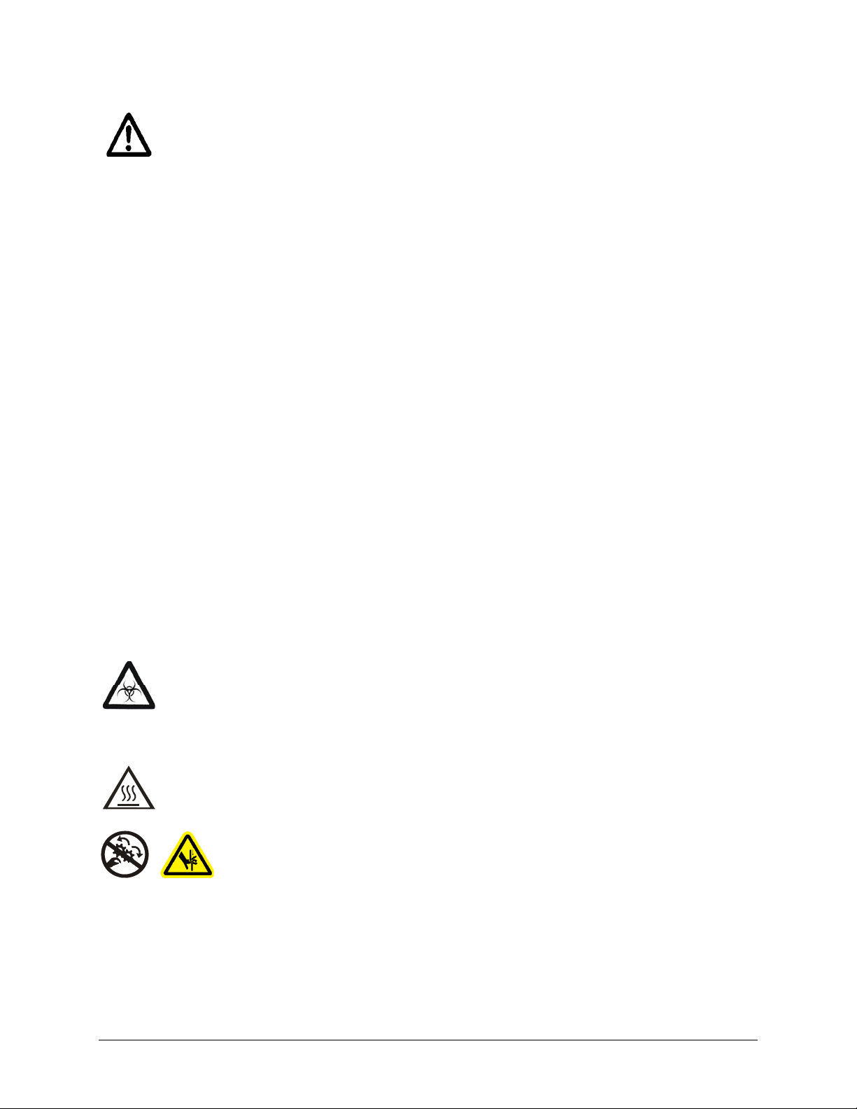
Warning! Potential Biohazards.
Some assays or specimens may pose a
biohazard. Adequate safety precautions should be taken as outlined in the assay’s
package insert. This hazard is noted by the symbol shown here. Always wear safety
glasses and appropriate protective equipment, such as chemically resistant rubber
gloves and apron.
Warning! Hot Surface.
The lamp assembly is hot when the instrument is turned
on. Turn off the reader and allow the lamp to cool down before attempting
replacement.
Warning! Pinch Hazard. Some areas of the dispense module can present
pinch hazards when the instrument is operating. The module is marked with
one of the symbols shown here. Keep hands/fingers clear of these areas
when the instrument is operating.
Synergy HT Operator’s Manual
Page 18

xiv | Preface
Precautions
The following precautions are provided to help avoid damage to the instrument:
Caution: Service.
The instrument should be serviced by BioTek authorized service
personnel. Only qualified technical personnel should perform troubleshooting and
service procedures on internal components.
Caution: Spare Parts.
Only approved spare parts should be used for maintenance.
The use of unapproved spare parts and accessories may result in a loss of warranty
and potentially impair instrument performance or cause damage to the instrument.
Caution: Environmental Conditions.
Do not expose the instrument to
temperature extremes. For proper operation, ambient temperatures should remain
within the range listed in the
Specifications section. Performance may be adversely
affected if temperatures fluctuate above or below this range. Storage temperature
limits are broader.
Caution: Sodium Hypochlorite.
Do not expose any part of the instrument to the
recommended diluted sodium hypochlorite solution (bleach) for more than 20
minutes. Prolonged contact may damage the instrument surfaces. Be certain to rinse
and thoroughly wipe all surfaces.
Caution: Power Supply.
Only use the power supply shipped with the instrument.
Operate this power supply within the range of line voltages listed on it.
Caution: Disposal.
This instrument contains printed circuit boards and wiring with
lead solder. Dispose of the instrument according to Directive 2002/96/EC, “on waste
electrical and electronic equipment (WEEE),” or local ordinances.
Caution: Warranty.
the warranty
Caution: Shipping Hardware.
.
Failure to follow preventive maintenance protocols may void
All shipping hardware must be removed before
operating the instrument and reinstalled before repackaging the instrument for
shipment.
Caution: Electromagnetic Environment.
Per IEC 61326-2-6 it is the user’s
responsibility to ensure that a compatible electromagnetic environment for this
instrument is provided and maintained in order that the device will perform as
intended.
Caution: Electromagnetic Compatibility.
Do not use this device in close
proximity to sources of strong electromagnetic radiation (e.g., unshielded intentional
RF sources), because these may interfere with the proper operation.
BioTek Instruments, Inc.
Page 19

CE Mark
Based on the testing described below and information contained
herein, this instrument bears the CE mark
See the Declaration of Conformity for more information.
Directive 2004/108/EC: Electromagnetic Compatibility
Emissions—Class A
The system has been type-tested by an independent, accredited testing laboratory
and found to meet the requirements of EN 61326-1: Class A for Radiated Emissions
and Line Conducted Emissions. Verification of compliance was conducted to the
limits and methods of EN 55011 – (CISPR 11) Class A. In a domestic environment it
may cause radio interference, in which case you may need to mitigate the
interference.
CE Mark | xv
Immunity
The system has been type-tested by an independent, accredited testing laboratory
and found to meet the requirements of EN 61326-1 and EN 61326-2-6 for Immunity.
Verification of compliance was conducted to the limits and methods of the
following:
EN 61000-4-2, Electrostatic Discharge
EN 61000-4-3, Radiated EM Fields
EN 61000-4-4, Electrical Fast Transient/Burst
EN 61000-4-5, Surge Immunity
EN 61000-4-6, Conducted Disturbances from RFI
EN 61000-4-11, Voltage Dips, Short Interruptions and Variations
Directive 2006/95/EC Low Voltage (Safety)
The system has been type-tested by an independent testing laboratory and was found
to meet the requirements of this Directive. Verification of compliance was conducted to
the limits and methods of the following:
EN 61010-1. “Safety requirement for electrical equipment for measurement, control and
laboratory use. Part 1, General requirements.”
EN 61010-2-081, “Particular requirements for automatic and semi-automatic laboratory
equipment for analysis and other purposes.”
Synergy HT Operator’s Manual
Page 20

xvi | Preface
EN 61010-2-010, “Particular requirements for laboratory equipment for the heating of
materials.”
Directive 2002/96/EC: Waste Electrical and Electronic Equipment
Disposal Notice: This instrument contains printed circuit boards and wiring with
lead solder. Dispose of the instrument according to Directive 2002/96/EC, “on waste
electrical and electronic equipment (WEEE)” or local ordinances.
Directive 98/79/EC: In Vitro Diagnostics (if labeled for this use)
• Product registration with competent authorities.
• Traceability to the U.S. National Institute of Standards and Technology (NIST).
• EN 61010-2-101, “Particular requirements for in vitro diagnostic (IVD) medical
equipment.”
Electromagnetic Interference and Susceptibility
USA FCC CLASS A
RADIO AND TELEVISION INTERFERENCE
Note:
This equipment has been tested and found to comply with the limits for a
Class A digital device, pursuant to Part 15 of the FCC Rules. These limits are
designed to provide reasonable protection against harmful interference when the
equipment is operated in a commercial environment. Like all similar equipment,
this equipment generates, uses, and can radiate radio frequency energy and, if not
installed and used in accordance with the instruction manual, may cause harmful
interference to radio communications. Operation of this equipment in a residential
area is likely to cause interference, in which case users will be required to correct
the interference at their own expense.
In order to maintain compliance with FCC regulations, shielded cables must be
used with this equipment. Operation with non-approved equipment or unshielded
cables is likely to result in interference to radio and television reception.
Canadian Department of Communications Class A
This digital apparatus does not exceed Class A limits for radio emissions from
digital apparatus set out in the Radio Interference Regulations of the Canadian
Department of Communications.
Le present appareil numerique n'emet pas de bruits radioelectriques depassant les
limites applicables aux appareils numerique de la Class A prescrites dans le
Reglement sur le brouillage radioelectrique edicte par le ministere des
Communications du Canada.
BioTek Instruments, Inc.
Page 21

User Safety | xvii
User Safety
This device has been type-tested by an independent laboratory and found to meet the
requirements of the following:
• Underwriters Laboratories UL 61010-1, “Safety requirements for electrical
equipment for measurement, control and laboratory use; Part 1: General
requirements.”
• Canadian Standards Association CAN/CSA C22.2 No. 61010-1, “Safety
requirements for electrical equipment for measurement, control and laboratory
use; Part 1: General requirements.”
• EN 61010 Standards, see
CE Mark starting on page xv.
Synergy HT Operator’s Manual
Page 22
xviii | Preface
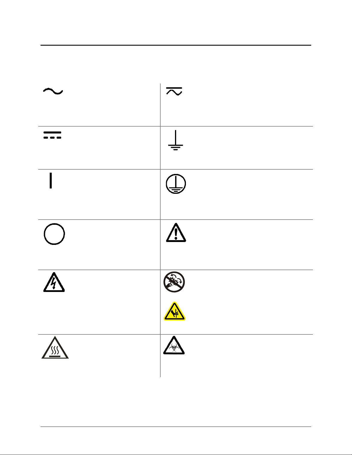
Safety Symbols
Some of these symbols appear on the instrument or accessories:
Alternating current
Courant alternatif
Wechselstrom
Corriente alterna
Corrente alternata
Both direct and alternating current
Courant continu et courant alternatif
Gleich - und Wechselstrom
Corriente continua y corriente alterna
Corrente continua e corrente alternata
Direct current
Courant continu
Gleichstrom
Corriente continua
Corrente continua
On (Supply)
Marche (alimentation)
Ein (Verbindung mit dem
Netz)
Conectado
Chiuso
Off (Supply)
Arrêt (alimentation)
Aus (Trennung vom Netz)
Desconectado
Aperto (sconnessione dalla
rete di alimentazione)
Warning, risk of electric shock
Attention, risque de choc
électrique
Gefährliche elektrische schlag
Precaución, riesgo de
sacudida eléctrica
Attenzione, rischio di scossa
elettrica
Earth ground terminal
Borne de terre
Erde (Betriebserde)
Borne de tierra
Terra (di funzionamento)
Protective conductor terminal
Borne de terre de protection
Schutzleiteranschluss
Borne de tierra de protección
Terra di protezione
Caution (refer to accompanying documents)
Attention (voir documents d’accompanement)
Achtung siehe Begleitpapiere
Atención (vease los documentos incluidos)
Attenzione, consultare la doc annessa
Warning, risk of crushing or pinching
Attention, risque d’écrasement et pincement
Warnen, Gefahr des Zerquetschens und
Klemmen
Precaución, riesgo del machacamiento y
sejeción
Attenzione, rischio di schiacciare ed
intrappolarsi
Warning, hot surface
Attention, surface chaude
Warnen, heiße Oberfläche
Precaución, superficie caliente
Attenzione, superficie calda
BioTek Instruments, Inc.
Warning, potential biohazards
Attention, risques biologiques potentiels
Warnung! Moegliche biologische Giftstoffe
Atención, riesgos biológicos
Attenzione, rischio biologico
Page 23
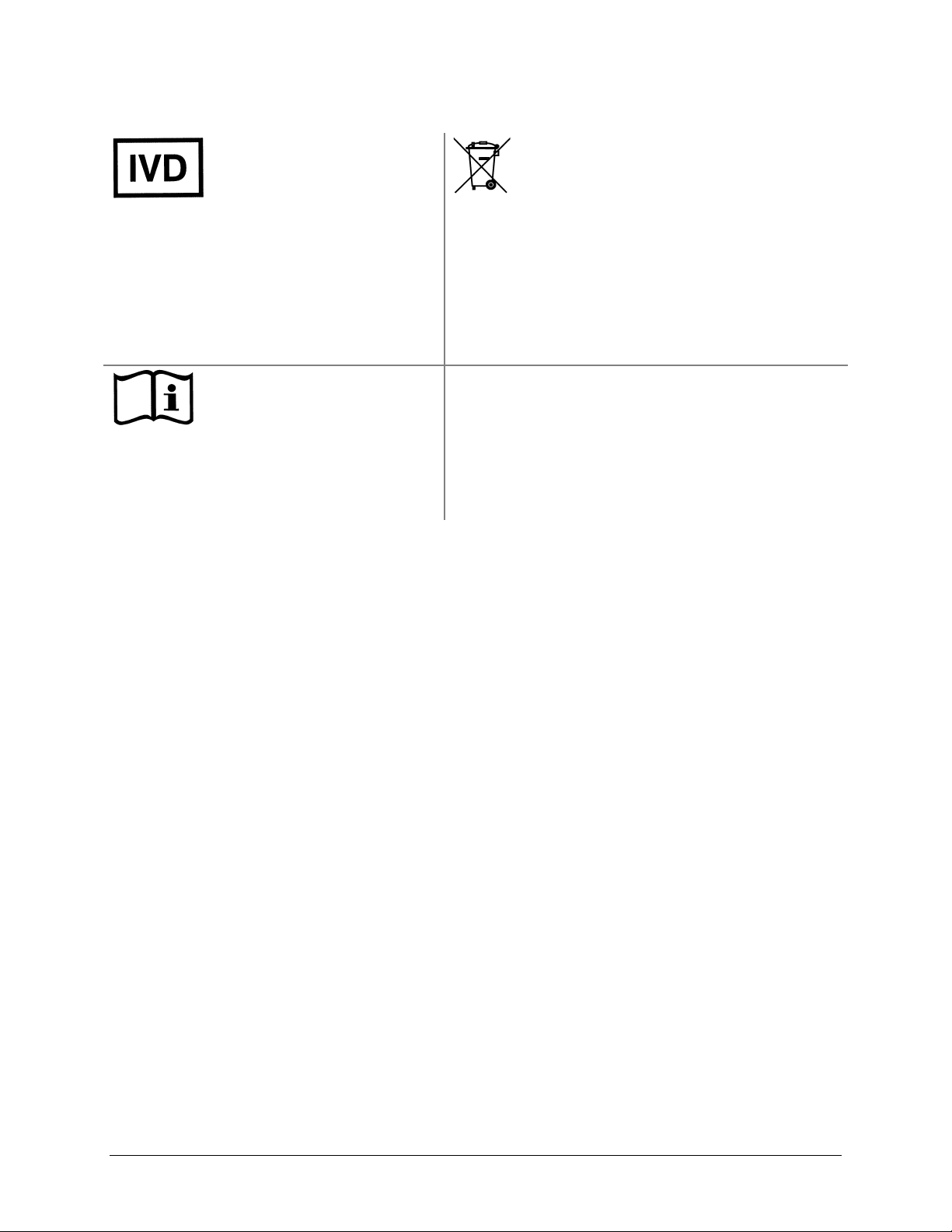
Safety Symbols | xix
In vitro diagnostic medical
device
Dispositif médical de
diagnostic in vitro
Medizinisches In-VitroDiagnostikum
Dispositivo médico de
diagnóstico in vitro
Dispositivo medico
diagnostico in vitro
Separate collection for electrical and
electronic equipment
Les équipements électriques et
électroniques font l’objet d’une collecte
sélective
Getrennte Sammlung von Elektro- und
Elektronikgeräten
Recogida selectiva de aparatos eléctricos y
electrónicos
Raccolta separata delle apparecchiature
elettriche ed elettroniche
Consult instructions for use
Consulter la notice d’emploi
Gebrauchsanweisung beachten
Consultar las instrucciones de
uso
Consultare le istruzioni per
uso
Synergy HT Operator’s Manual
Page 24

xx | Preface
BioTek Instruments, Inc.
Page 25

Chapter 1
Introduction
This chapter introduces the Synergy HT, describes its key features,
lists its package contents, and provides contact information for
technical assistance.
Synergy HT Multi-Mode Microplate Reader ................................. 2
Features ............................................................................... 3
Package Contents ................................................................... 4
Optional Accessories ............................................................... 5
Product Support & Service ....................................................... 6
Technical Assistance Center (TAC) ........................................ 6
Returning Instruments for Service/Repair .............................. 6
Contacting BioTek for Applications Support ............................ 6
Page 26

2 | Chapter 1: Introduction
Synergy HT Multi-Mode Microplate Reader
The Synergy HT is a single-channel absorbance, fluorescence, and luminescence
microplate reader. It is computer-controlled using BioTek’s Gen5 software for all
operations including data reduction and analysis.
version
2.24 or greater is required for use with Gen5. The Synergy HT is robot
accessible and compatible with BioTek’s BioStack Microplate Stacker.
Note: Synergy HT basecode software
When making
fluorescence determinations, the Synergy HT uses a tungsten quartz
halogen lamp with interference filters for wavelength specificity in conjunction with a
photomultiplier (PMT) tube detector. The Synergy HT has both top and bottom probes for
fluorescence measurements. The top probe can be adjusted vertically for the correct
reading height, via Gen5’s Read Height reading parameter (see
Started
Luminescence is measured by the low-noise PMT detector through an empty filter
).
Chapter 3, Getting
position in the Emission filter wheel. A filter can also be left in place if light filtering is
necessary.
Absorbance measurements are made by switching to a xenon flash lamp and a
monochromator for wavelength selection. The use of a xenon flash lamp allows for both
UV and visible light absorbance measurements. The monochromator provides wavelength
selection from 200 to 999 nm in 1-nm increments.
The Synergy HT has a 4-Zone
temperature control from 4°C (39.2°F) over ambient to
50°C (122°F) that ensures superior temperature uniformity necessary for kinetic assays.
Internal plate shaking is also supported.
All Synergy HT models support the reading of 6-, 12-, 24-, 48-, 96-, and 384-well
microplates with standard 128 x 86 mm geometry, as well as the BioTek Take3 and Take3
Trio Micro-Volume Plates. Absorbance mode reads plates up to 0.8” (20.3 mm) in height;
fluorescence mode reads plates up to 1.25” (31.75 mm). Polymerase Chain Reaction (PCR)
tubes up to 1.25” (31.75 mm) are also readable with the use of existing adapter plates.
The Time-Resolved (TR) option allows
time-resolved fluorescence measurements by
using the xenon flash light source in conjunction with the PMT measurement detector. A
special cartridge installed in the Excitation filter wheel location is required.
Models with
microplates with standard 128 x 86 mm geometry. An
injectors support dual-reagent dispensing to 6-, 12-, 24-, 48-, and 96-well
external dispense module
pumps fluid from the supply bottles to the two injectors located inside the instrument.
Both injectors are positioned directly above the bottom probe, and fluid is injected into one
well at a time.
BioTek Instruments, Inc.
Page 27

Features | 3
Features
• Operated using BioTek’s Gen5 Data Analysis Software
• Dual-optics design, with separate fluorescence and absorbance channels
• 3 mm top and 5 mm bottom fluorescence probes (standard configuration)
• Optional 1.5 mm top/bottom, 3 mm bottom fluorescence probes (custom
configurations)
• Optional Time-Resolved Fluorescence (TRF) capability (“T” models, e.g., SIAFRT)
• Fluorescence λ ranges:
Standard low-noise PMT
Optional red-extended PMT
• Absorbance λ range of 200 to 999 nm
¾ Excitation: 300 to 650 nm (200 to 700 nm with “T” models)
¾ Emission: 300 to 700 nm
¾ Excitation: 300 to 650 nm (200 to 800 nm with “T” models)
¾ Emission: 300 to 800 nm
• Absorbance OD range from 0.000 to 4.000 OD
• Low, Medium, High and Variable plate-shaking speeds with adjustable durations
• All models read 6-, 12-, 24-, 48-, 96- and 384-well microplates
• Injector models dispense to 6-, 12-, 24-, 48-, and 96-well microplates
• Operates from 100 to 240 V~ (± 10%) @ 50 to 60 Hz
• One serial COM port (9-pin female connector)
• One USB port
• 4-Zone incubation to 50ºC (122ºF)
• Optional dual-reagent dispensing capability
Synergy HT Operator’s Manual
Page 28

4 | Chapter 1: Introduction
Package Contents
Part numbers and package contents are subject to change. Contact
BioTek Customer Care with any questions.
Item Part #
Synergy HT Operator’s Manual 7091000
injectors:
Power supply
Power cord set (specific to installation environment):
Europe (Schuko)
USA/International
United Kingdom
Australia/New Zealand
RS-232 serial cable 75034
USB cable
with USB Driver Software
Wrench 48576
Fluorescence lamp assembly (Note: The replacement lamp assembly is
PN 7080500)
Filter “plugs” (2) (also referred to as “dummy filters” or “blanks”) 7082073
Plastic storage bag and fastener strips —
Time-Resolved Fluorescence cartridge assembly (“T” models only) 7090523
Models with injectors (“SIAFRTD” “SIAFRTD-CUSTOM”), an external
dispense module (packed separately), with the following accessories:
Outlet tubes (2, plus 2 spare) from dispense module to instrument
Inlet tubes (2) from supply bottles to syringe drives
250 µl syringes (2)
Syringe thumbscrews (2)
Priming plate
Injector tip priming trough
Dispense module communication cable
Dispense module front cover
Supply bottles (2, 30 mL)
Supply bottle holder assemblies (2)
Injector tip cleaning stylus and plastic storage bag
7090204
7080501
7082120
7082121
7083000
7132158
7132169
7082137
7122609
7090564
2872304
models
with
76061
all other
models:
76077
75010
75011
75012
75013
75108
19511
75107
BioTek Instruments, Inc.
Page 29
Optional Accessories | 5
Optional Accessories
Accessory availability and part numbers are subject to change. Contact
BioTek Customer Care with questions or visit www.biotek.com and use
the Accessories search tool.
Item Part #
7-filter Absorbance Test Plate
7260522
Fluorescence Test Plate
Product Qualification (IQ-OQ-PQ) package
PCR Tube Adapter Plates
Terasaki Adapter Plate
Take3 Micro-Volume Plate
Take3 Trio Micro-Volume Plate
BioCell Quartz Vessel and Adapter Plate
Additional Fluorescence Filters; contact BioTek for part numbers and availability
The Synergy HT is compatible with the BioStack Microplate Stacker. Contact BioTek or
visit our website to learn more.
7092092
7090521
6002072 and
6002076
7330531
TAKE3
Take3Trio
7272051/7270512
For Use with Liquid Tests (see Chapter 5) Part #
Absorbance Liquid Test Solutions:
BioTek Wetting Agent Solution
BioTek QC Check Solution #1
25 mL
125 mL
Dispense Module Liquid Test Solution:
BioTek Green Test Dye
BioTek Blue Test Dye
BioTek QC (Yellow) Test Dye
Individual Fluorescence Liquid Test Solutions:
Sodium Fluorescein Powder
Liquid Test Kit using Sodium Fluorescein
Liquid Test Kit using Methylumbelliferone (“MUB”)
7773002
7120779
7120782
7773003
7773001
7120782
98155
7160013
7160012
Synergy HT Operator’s Manual
Page 30

6 | Chapter 1: Introduction
Product Support & Service
Technical Assistance Center (TAC)
If your instrument(s) or software fails to function properly, if you have questions about
how to use or maintain our products, or if you need to send an instrument to BioTek
for service or repair, please contact our Technical Assistance Center. BioTek’s “TAC” is
open from 8:30 AM to 5:30 PM (EST), Monday through Friday, excluding standard U.S.
holidays. You can send a fax or an e-mail any time. You can also request technical
assistance via our website:
Phone: (800) 242-4685 or Fax: (802) 654-0638 E-Mail: tac@biotek.com
(802) 655-4740
Please be prepared to provide the following information:
• Your name and company information, along with a daytime phone or fax
number, and/or an e-mail address
• The product name, model, and serial number
www.biotek.com.
Web: www.biotek.com
• The onboard software part number and version (available through Gen5 at
System > Instrument Control > Information)
• Gen5 software version information (
Help > About Gen5)
• For troubleshooting assistance or instruments needing repair, the specific steps
that produce your problem and any error codes displayed in Gen5
(see also
Appendix C, Error Codes)
Returning Instruments for Service/Repair
If you need to return an instrument to BioTek for service or repair, please contact the
TAC for a Return Materials Authorization (RMA) number before shipping the
instrument. Repackage the instrument properly (see
Chapter 2, Installation), write
the RMA number on the shipping box, and ship to BioTek.
Contacting BioTek for Applications Support
BioTek’s fully equipped Application Laboratory provides our on-staff scientists with
the means to assist you with the integration of our instrumentation and software with
your unique scientific applications. If you are having difficulty with optimizing
fluorescence sensitivity or integrating a unique data reduction transformation, or you
are just looking for a recommendation on an appropriate fluorophore, contact us.
Phone: (888) 451-5171 E-Mail: applications@biotek.com
BioTek Instruments, Inc.
Page 31

Chapter 2
Installation
This chapter includes instructions for unpacking and setting up
the Synergy HT and, if applicable, the external dispense module.
Instructions are also included for repackaging the reader and
dispense module for shipment.
Product Registration ............................................................... 8
1: Unpack and Inspect the Reader ............................................ 8
2: Remove the Shipping Panel ............................................... 10
3: Remove the Microplate Carrier Shipping Screw ..................... 12
4: Install the Fluorescence Lamp Assembly .............................. 13
5: Select an Appropriate Location ........................................... 14
6: Connect the Power Supply ................................................. 14
7: Unpack and Inspect the Dispense Module ............................ 15
8: Install the Dispense Module ............................................... 19
9: Connect the Host Computer ............................................... 23
10: Install Gen5 Software ...................................................... 23
11: Turn on the Reader ......................................................... 23
12: Establish Communication ................................................. 24
13: Run a System Test ......................................................... 25
14: Test the Injector System ................................................. 26
Operational/Performance Qualification ..................................... 28
Repackaging and Shipping Instructions ................................... 28
Page 32

8 | Chapter 2: Installation
Product Registration
Please register your product with BioTek to ensure that you receive important information
and updates about the products you have purchased. Contact the Customer Resource
Center (CRC) at www.biotek.com or by calling 888-451-5171 or 802-655-4740.
1: Unpack and Inspect the Reader
Important! Save all packaging materials. If you need to ship the
reader to BioTek for repair or replacement, you must use the
original materials. Using other forms of commercially available
packaging, or failing to follow the repackaging instructions, may
void your warranty. Improper packaging that results in damage
to the instrument may lead to additional charges.
During the unpacking process, inspect the packaging, reader, and
accessories for shipping damage. If the reader is damaged, notify
the carrier and your BioTek representative. Keep the shipping
boxes and the packaging materials for the carrier’s inspection.
BioTek will arrange for repair or replacement of your reader
immediately.
1. Open the outer shipping box. Remove the foam blocks to access the inner box.
Corner shipping block
Inner shipping box
Outer shipping box
Figure 1-A: Unpacking the reader’s outer shipping box
BioTek Instruments, Inc.
Page 33

1: Unpack and Inspect the Reader | 9
V
2. Carefully open the inner shipping box. Remove the accessories box and set it aside.
Remove the vertical supports.
Warning! The instrument weighs approximately 38 pounds (17 kg).
Use two people when lifting and carrying the instru ment.
3. The Synergy HT is attached to a shipping panel that has two handles for lifting.
Locate and grasp the handles. Carefully lift the reader out of the box and place it on
a level surface. Remove the protective plastic bag.
4. Place all packing material back into the shipping box for reuse if the reader needs to
be shipped again.
See Package Contents in Chapter 1 for assistance with identifying
the contents of the accessories box.
Accessories box
ertical supports
Shipping panel
Inner shipping box
Figure 1-B: Unpacking the reader’s inner shipping box
Synergy HT Operator's Manual
Page 34

10 | Chapter 2: Installation
2: Remove the Shipping Panel
1. Carefully tip the reader onto its back.
2. Using a screwdriver, remove the four screws and washers attaching the shipping
panel to the bottom of the reader. See
3. Carefully set the reader upright.
4. Locate the supplied plastic tool storage pocket. Place the screws and washers inside
the bag. Use the supplied fastener strips to attach the pocket to the back of the reader
for storage. Do not block any air vents. See
5. Place the panel back into the inner shipping box for storage.
Important: Reattach the shipping panel before
repackaging the Synergy HT for shipment.
Figure 2 on the next page.
Figure 3 on the next page.
BioTek Instruments, Inc.
Page 35

2: Remove the Shipping Panel | 11
Figure 2: Removing the shipping panel
Figure 3: Storage pocket on the rear of the instrument
(wrench, carrier shipping screw, and warning tag shown)
Synergy HT Operator's Manual
Page 36

12 | Chapter 2: Installation
3: Remove the Microplate Carrier Shipping Screw
Important: Remove the microplate carrier shipping
1. Pull down the microplate loading door on the front of the reader.
2. Using the supplied wrench, remove the carrier shipping screw with its o-ring and
warning tag.
3. Place the wrench, screw, o-ring, and tag in the plastic tool storage bag that you
attached to the back of the reader.
Shipping screw
screw before turning on the Synergy HT.
(with o-ring)
Wrench
Shipping screw
warning tag
Figure 4: Removing the microplate carrier shipping screw
Important: Replace the microplate carrier shipping
screw before repackaging the Synergy HT for shipment.
Please contact BioTek if you have misplaced the screw (PN
7092071) and/or its o-ring (PN 49259).
BioTek Instruments, Inc.
Page 37

4: Install the Fluorescence Lamp Assembly | 13
4: Install the Fluorescence Lamp Assembly
Important: Do not touch the glass lenses! Fingerprints on
1. Locate the lamp assembly in the accessories box. The lamp is attached to a metal
bracket that also holds a condenser lens and a heat absorber. Two cables are attached
to the back of the lamp.
2. Open the hinged door on the front of the reader by pressing on its lower left and
right corners. The lamp compartment is on the far left.
the condenser lens or heat absorber may negatively affect
performance.
Warning! The fluorescence lamp assembly is hot when the
instrument is powered on. If the instrument is on, turn it off and
allow the lamp to cool down before attempting to replace it.
3. Orient the lamp assembly as shown below. Slide the assembly all the way into the
compartment.
4. Plug the lamp cables into the power source located to the right of the lamp. Either
cable can be plugged into either socket.
5. Close the hinged door.
Figure 5: Installing the fluorescence lamp assembly (replacement lamp PN 7080500)
Synergy HT Operator's Manual
Page 38

14 | Chapter 2: Installation
5: Select an Appropriate Location
Install the Synergy HT on a level surface in an area where ambient temperatures between
18ºC (64ºF) and 40ºC (104ºF) can be maintained.
The reader is sensitive to extreme environmental conditions. Avoid the following:
•
Excessive humidity: Condensation directly on the sensitive electronic circuits
can cause the reader to fail internal self-checks. The specified relative humidity
range for this reader is from 10% to 85% (non-condensing).
•
Excessive ambient light: Bright sunlight or strong incandescent light may affect
the reader’s optics and readings, reducing its linear performance range.
•
Dust: Readings may be affected by extraneous particles (such as dust) in the
microplate wells. A clean work area is necessary to ensure accurate readings.
If you will be installing BioT ek’s BioStack Microplate Stacker for
operation with the Synergy HT, you may wish to seat the BioStack and
the reader in their aligning plates at this time. Refer to the BioStack
Operator’s Manual for more information.
6: Connect the Power Supply
Warning! Power Rating. The power supply must be
connected to a power receptacle that provides voltage and
1. Connect the power cord to the external power supply.
2. Locate the power inlet on the rear of the reader.
current within the specified rating for the system. Use of an
incompatible power receptacle may produce electrical shock
and fire hazards.
Warning! Electrical Grounding. Never use a plug adapter to
connect primary power to the external power supply. Use of an
adapter disconnects the utility ground, creating a severe shock
hazard. Always connect the power cord directly to an
appropriate receptacle with a functional ground.
3. Plug the rounded end of the power supply’s line cord into the power inlet.
4. Plug the power cord into an appropriate power receptacle.
BioTek Instruments, Inc.
Page 39

7: Unpack and Inspect the Dispense Module | 15
Power inlet for injector
models (as shown):
Power inlet for noninjector models:
Figure 6: Power inlet on the rear of the instrument
24 VDC
130 W
24 VDC
center positive
7: Unpack and Inspect the Dispense Module
Applies only to Synergy HT models with injectors.
Important! Save all packaging materials. If you need to ship
the dispense module to BioTek for repair or replacement, you
must use the original materials. Using other forms of
commercially available packaging, or failing to follow the
repackaging instructions, may void your warranty.
During the unpacking process, inspect the packaging, module,
and accessories for shipping damage. If the reader is damaged,
notify the carrier and your BioTek representative. Keep the
shipping boxes and the packaging materials for the carrier’s
inspection. BioTek will arrange for repair or replacement of
your reader immediately.
1. Open the outer shipping box. Remove the foam cap, inner shipping box, and
accessories box.
Synergy HT Operator's Manual
Page 40

16 | Chapter 2: Installation
Top foam end
cap
Inner shipping box
(Dispense module)
Bottom foam
end cap
Accessories
box
Outer
shipping box
Figure 7: Unpacking the dispense module’s outer shipping box
2. Using no sharp tools, open the box containing the dispense module. Remove the
two reagent bottle holders and the cardboard shipping insert. Lift out the module
and place it on a level surface.
Cardboard insert
Shipping insert
Reagent
bottle holders
Dispense
Dispense
module
module
Inner shipping
Inner
shipping box
box
Figure 8: Unpacking the dispense module’s inner shipping box
BioTek Instruments, Inc.
Page 41

7: Unpack and Inspect the Dispense Module | 17
3. Open the accessories box. Remove and identify its contents (see
next page):
• 2 inlet tubes, packaged in plastic cylinders
• 4 outlet tubes, packaged in plastic bags (PN 7082120)
• 2 syringes, packaged in boxes
• 1 priming plate
• 2 reagent bottles
• 1 injector tip priming trough (small, plastic cup)
• 1 plastic tool storage bag with fastener strips
• 2 metal thumbscrews
• 1 stylus (wire) packaged in a small plastic cylinder
• 1 dispense module cover
• 1 dispense module cable
Figure 9 on the
Synergy HT Operator's Manual
Page 42

18 | Chapter 2: Installation
Top foam
end cap
Inlet tubes (2)
Outlet tubes (4)
Dispense module
cable
Dispense
module cover
Syringes (2)
Accessories
box
Bottom foam
end cap (with
cutouts)
Figure 9: Unpacking the dispense module’s accessories
BioTek Instruments, Inc.
Page 43

8: Install the Dispense Module
Applies only to Synergy HT models with injectors.
Refer to the figures on the next two pages for guidance while
performing these steps.
1. Place the dispense module to the left side or on top of the reader. See the photos on
the next page.
8: Install the Dispense Module | 19
2. On the rear panel of the Synergy HT, identify the
SYRINGE 1 and SYRINGE 2
tubing ports. Remove the nylon screws from both ports.
3. Open two
of the plastic bags containing the outlet tubes (labeled as PN 7082120).
Remove the clear plastic fitting covers from the tubes. Put the other two bags in a
safe place; they are spares.
4. Place the nylon screws and the plastic fitting covers in the plastic tool
storage bag.
Use the supplied fastener strips to attach the bag to the rear panel of the dispense
module.
5. Remove the two
6. Identify the two circular
with a left-pointing arrow. See
When installing the inlet and outlet tubes, do not use any tools.
Finger-tighten only!
inlet tubes from their protective plastic canisters.
syringe valves on the dispense module. Each is labeled
Figure 12 on the next page.
7. Screw the fitting of one inlet tube into the right side of the Syringe 1 valve.
8. Screw one end of one outlet tube into the left side of the Syringe 1 valve.
Screw the other end of the outlet tube into the SYRINGE 1 port on the rear of the
9.
Synergy HT.
10. Repeat steps 7 through 9 to attach the inlet and outlet tubing for Syringe 2.
11. Seat the outlet tubes in the
Synergy HT Operator's Manual
clip to the left of the Syringe 2 valve.
Page 44

20 | Chapter 2: Installation
Figures 10 and 11: Possible locations for the dispense module,
to the left or on top of the instrument.
Outlet
tubes
Figure 12: Initial setup of the dispense module
Inlet
tubes
Syringe
valves
BioTek Instruments, Inc.
Page 45

8: Install the Dispense Module | 21
12. Remove the two syringes from their protective boxes. They are identical and
interchangeable. Each syringe should already be assembled in one piece, but if for
some reason there are two separate pieces, assemble them now: insert the white tip
of the syringe plunger into the barrel of the syringe and gently push it all the way
into the barrel.
13. Install both syringes:
• Hold the syringe vertically with the threaded end at the top and the knurled
steel end at the bottom.
• Screw the threaded end of the syringe into the bottom of the
syringe valve.
Finger-tighten only.
• Carefully pull down the knurled steel end of the syringe until it is resting
inside the hole in the
• Pass a metal
thumbscrew up through this hole and thread it into the bottom
bracket.
of the syringe. Hold the syringe from rotating while tightening the
thumbscrew. Finger-tighten only.
The installed syringes should resemble the following:
Syringes
Syringe
brackets
Thumbscrews
Figure 13: The dispense module with the syringes installed
Synergy HT Operator's Manual
Page 46

22 | Chapter 2: Installation
14. Locate the dispense module cable. Plug one end into the port on the left side of the
dispense module. Plug the other end into the “Dispenser Port” on the rear panel of
the Synergy HT.
One end of the cable
connected to the port on
the side of the dispense module
The other end
connected to
the reader’s
Dispenser Port
Figure 14: Dispense module connected to the reader (rear view)
15. Locate the injector tip-cleaning stylus, packaged in a small plastic cylinder. Attach
the cylinder to the back of the dispense module for storage.
BioTek Instruments, Inc.
Page 47

9: Connect the Host Computer | 23
9: Connect the Host Computer
The Synergy HT is equipped with two types of communication ports: Serial (RS-232) and
USB. Both ports are located on the rear panel of the reader.
• Both types of cables are included in the accessories box. Determine which cable is
supported by the
• Connect one end to the appropriate port on the reader (see photo below) and the
other end to the appropriate port on the host computer.
host computer.
Figure 15: RS-232 serial and USB ports on the rear panel (injector model shown)
10: Install Gen5 Software
The Synergy HT is controlled by BioTek’s Gen5 software running on a host computer.
There is a certain sequence of events that must be followed to ensure that the software is
properly installed and configured. Please follow the instructions provided in
Getting Started Guide
to install the software.
11: Turn on the Reader
Locate the power switch on the front panel and turn on the Synergy HT. The reader will
automatically initiate a System Test and eject the microplate carrier.
Gen5’s
Synergy HT Operator's Manual
Page 48

24 | Chapter 2: Installation
Figure 16: Carrier eject button (top) and power ON/OFF switch
12: Establish Communication
Important: If you are using the USB cable, refer to the instructions
that shipped with the “USB Driver Software” CD to install the
necessary drivers and identify the Com Port number.
1. Start Gen5 and log in if prompted. The default System Administrator password is
admin.
2. Go to the Gen5 main screen:
• Gen5 version 2.x users: From the Task Manager, select
Menu
• Gen5 version 1.x users: From the Welcome screen, select
3. Select
4. Set the
.
System > Instrument/Reader Configuration and click Add.
Reader Type to Synergy.
Setup > Go to System
System Menu.
5. Set the
Com Port to the computer’s COM port to which the reader is connected.
• If using the USB cable, the information can be found via the Windows
Panel, under Ports in the Hardware/Device Manager area of System Properties
(e.g., USB Serial Port (COM5)).
BioTek Instruments, Inc.
®
Control
Page 49

13: Run a System Test | 25
6. Click the Test Comm button. Gen5 will attempt to communicate with the reader. If
the communication attempt is successful, return to Gen5’s main screen.
If the communication attempt is
not successful, try the following:
• Is the reader connected to the power supply and turned on?
• Is the communication cable firmly attached to both the reader
and the computer?
• Did you select the correct Reader Type in Gen5?
• Try a different COM port.
• If using the USB cable, did you install the driver software?
If you remain unable to get Gen5 and the reader to communicate with
each other, contact BioTek’s Technical Assistance Center.
13: Run a System Test
Running a System Test will confirm that the reader is set up and running properly, or will
provide an error code if a problem has been detected.
1. Select
select the Synergy HT and click
System > Diagnostics > Run System Test. If prompted to select a reader,
OK.
2. When the test is complete, a dialog will appear to request additional information.
Enter the information (if required) and click
OK.
3. The results report will appear. Scroll down toward the bottom, the text should read
“SYSTEM TEST PASS.”
• You may wish to print the report and store it with your Installation records.
• The software stores system test information in its database; you can retrieve it
at any time.
If an error code is returned, turn to Appendix C, Error Codes and
look up the code. If the problem is something you can fix, do so now
and run another System Test. If the problem is something you cannot
fix, or if the test continues to fail, contact BioTek’s Technical
Assistance Center.
4. Models with injectors: Keep the software open and proceed to
All other models: The installation and setup process is complete!
14: Test Injector System.
Close the software and turn to page 28 to read
about
Operational/Performance Qualification.
Synergy HT Operator's Manual
Page 50

26 | Chapter 2: Installation
14: Test the Injector System
Applies only to Synergy HT models with injectors.
1. If necessary, press the button above the power switch to eject the microplate carrier.
2. Place the
3. Place the
tip priming trough in the left-rear pocket of the carrier.
priming plate on the carrier.
Priming plate
Tip priming trough
Figure 17: Installing the tip priming trough and
priming plate on the microplate carrier
4. Fill the two
reagent bottles with distilled or deionized water. Place the bottles in
their holders, and place the holders directly in front of the syringes. Insert the inlet
tubes into the bottles.
The dispense module’s setup should resemble the photo in Figure 18.
Make any final adjustments, if necessary.
BioTek Instruments, Inc.
Page 51

14: Test the Injector System | 27
Figure 18: The fully assembled dispense module
5. Select System > Reader/Instrument Control > Synergy (Com<#>)
6. Click the
7. With
Dispenser tab.
Dispenser set to 1, set the Volume to 5000 µl and click Prime.
The syringe should move down and up repeatedly, drawing fluid from the bottle.
The fluid should pump through the tubing and dispense into the priming plate.
Examine the fittings; no leaks should be detected.
If leaks are detected, tighten all fittings and repeat the prime. If leaks are still
detected, contact BioTek’s Technical Assistance Center.
8. When the prime finishes, set
Volume to 2000 µL and click Purge to clear the fluid
lines.
9. Set
Dispenser to 2 and repeat steps 7 and 8.
10. When finished, remove and empty the priming plate.
11. Close the software.
The installation and setup process is complete! Turn to the next page to read about
Operational/Performance Qualification.
Synergy HT Operator's Manual
Page 52

28 | Chapter 2: Installation
Operational/Performance Qualification
Your Synergy HT Multi-Detection Microplate Reader was fully tested at BioTek prior
to shipment and should operate properly following the successful completion of the
installation and setup procedures described throughout this chapter.
If you suspect that problems occurred during shipment, if you received the reader back
from BioTek following service or repair, and/or if regulatory requirements dictate that
Operational/Performance Qualification is necessary, turn to
Qualification
Synergy HT.
An Installation-Operational-Performance (IQ/OQ/PQ) package for the
now to learn about BioTek’s recommended OQ/PQ procedures for the
Synergy HT is available for purchase (PN 7090521). Contact your local
BioTek dealer for more information.
Chapter 4, Instrument
Repackaging and Shipping Instructions
Warning! If the reader and/or dispense module has been exposed to
potentially hazardous material, decontaminate it to minimize the risk
to all who come in contact with the reader during shipping, handling
and servicing. Decontamination prior to shipping is required by the
U.S. Department of Transportation regulations. See Appendix A for
decontamination instructions.
Caution! Remove the microplate and tip prime trough (if equipped)
from the carrier before shipment. Spilled fluids can contaminate the
optics and damage the instrument.
BioTek Instruments, Inc.
Page 53

Repackaging and Shipping Instructions | 29
Important!
The instrument’s packaging design is subject to change. If the
instructions in this section do not appear to apply to the packaging
materials you are using, please contact BioTek’s Technical Assistance
Center for guidance.
Replace the microplate carrier shipping screw and the shipping panel
before repackaging the reader for shipment. Please contact BioTek if
you have misplaced either of these items.
If you need to ship the Synergy HT and/or the dispense module to
BioTek for service or repair, be sure to use the original packaging
materials. Other forms of commercially available packaging are not
recommended and can void the warranty.
The shipping materials are designed to be used no more than five
times. If the original materials have been damaged, lost, or used more
than five times, contact BioTek to order replacements (PN 7093001 for
the reader, PN 7083001 for the dispense module). See page 6 for
contact information.
Perform these steps to prepare the
1. Contact BioTek’s Technical Assistance Center for an RMA (Return Materials
Authorization) number before returning equipment for service. See page 6 for
contact information.
2. Decontaminate the reader and, if attached, the dispense module, according to
the instructions provided in
3. If you will also be shipping the dispense module, perform these steps now:
a. With the reader on, start Gen5 and select
Control > Synergy (COM<#>)
b. Click the
c. Click the
d. The Syringe 1 bracket will lower. Remove the thumbscrew from underneath
the bracket. Carefully unscrew the top of the syringe from the syringe
valve. Lift out the syringe and store it in its original box.
e. Set the Dispenser number to 2. Repeat steps
f. Fully detach the dispense module from the reader. Replace the two nylon
screws into the Syringe 1 and 2 tubing ports on the rear of the reader. (The
screws should be stored in the plastic bag attached to the back of the
module.) Set the module aside for the moment.
reader for shipment:
Appendix A.
System > Reader/Instrument
.
Dispenser tab. Ensure that “Dispenser” is set to 1.
Maintenance button.
c and d for Syringe 2.
Synergy HT Operator's Manual
Page 54

30 | Chapter 2: Installation
4. If you have not already done so, retract the microplate carrier and then turn off
and unplug the reader.
5. Remove the lamp assembly and pack it in bubble wrap (see p. 13).
6. Replace the microplate carrier shipping screw (see p. 12).
7. Tip the reader onto its back feet. Attach the shipping panel to the bottom of
the reader using the four screws and washers (see p. 10).
8. Wrap the plastic bag around the reader and shipping panel.
9. Locate the original outer shipping box. Place four foam blocks in the four
bottom corners of the box. Place the
(see p. 8 and 9).
10. Grasp the handles on the shipping panel and carefully lower the reader into the
inner shipping box.
11. Slide the foam vertical supports into place around the reader. Place the
accessories box on top.
12. Close and seal the inner box with tape.
inner shipping box inside the outer box
13. Place four foam corner blocks around the inner shipping box. Close and seal
the outer box with tape.
14. Write the RMA number in large clear numbers on the outside of the box. Ship
the box to BioTek.
Perform these steps to prepare the
1. If you have not already done so:
• Contact BioTek’s Technical Assistance Center for an
dispense module for shipment:
RMA (Return Materials
Authorization) number and shipping address before returning equipment
for service. See page 6 for contact information.
• Decontaminate the module according to the instructions in
Appendix A.
• Remove the two syringes (see step 3 on the previous page) and store them
in their original boxes.
• Detach the dispense module outlet tubes and communication cable from the
reader. Replace the two nylon screws into the Syringe 1 and 2 tubing ports
on the rear of the reader.
Refer to the illustrations in 7: Unpack and Inspect the Dispense
Module starting on page 15 when performing these steps.
2. Remove the two inlet tubes from the syringe valves and store them in their
plastic canisters.
3. Remove the two outlet tubes from the syringe valves. Attach the clear plastic
fitting covers to the fittings of the outlet tubes. Place the tubes in a plastic bag.
BioTek Instruments, Inc.
Page 55

Repackaging and Shipping Instructions | 31
4. Place the dispense module inside the inner shipping box. Slide the cardboard
shipping insert down around the module. Pack the reagent bottle holders in
bubble wrap and place them on top of the module. Seal the box with tape.
5. Locate the original accessories shipping box and foam end caps. Place the
bottom foam end cap into the box.
6. Place the syringes, the inlet tubes, and the outlet tubes inside the cutouts of the
bottom foam end cap in the accessories box. Place the dispense module cover
on top of the accessories.
7. Cover the accessories with the top foam end cap, place the dispense module
cable inside the top of the end cap, and seal the box with tape.
8. Locate the original outer shipping box and foam end caps. Insert the bottom
foam end cap. Lower the dispense module box into the end cap.
9. Insert the accessories box alongside the dispense module box.
10. Insert the top foam end cap. Close and seal the outer box with tape.
11. Write the RMA number in large clear numbers on the outside of the box. Ship
the box to BioTek.
Synergy HT Operator's Manual
Page 56

32 | Chapter 2: Installation
BioTek Instruments, Inc.
Page 57

Chapter 3
Getting Started
This chapter describes some of the Synergy HT’s key components
and provides an introduction to using Gen5 to control the
instrument.
Key Components .................................................................. 34
Power Switch, Carrier Eject Button, Microplate Carrier ........... 34
Lamp Assembly and Filter Wheel Access .............................. 35
Excitation and Emission Filter Wheels ................................. 36
Installing the Time-Resolved Fluorescence Cartridge ............. 39
Configuring the System for Luminescence Measurements ...... 40
The External Dispense Module ........................................... 41
Gen5 Software ..................................................................... 44
Viewing/Updating the Filter and Wavelengths Tables ............. 44
Creating Protocols and Experiments.................................... 45
Controlling the Dispense Module ........................................ 49
Recommendations for Optimum Performance ........................... 51
Page 58

34 | Chapter 3: Getting Started
Key Components
Power Switch, Carrier Eject Button, Microplate Carrier
Microplate
Well A1
Carrier eject button
Power switch
carrier
Figure 19: Power switch, carrier eject button, microplate carrier
• The power switch is labeled “I/O,” indicating on and off, respectively. An LED
on the switch indicates that the power is on.
• The
microplate carrier eject button can be used to move the microplate carrier
into or out of the measurement chamber, and also to stop the instrument from
“beeping” when it encounters an error.
• The
microplate carrier supports microplates and adapter plates as described in
Appendix D, Specifications . The plate is positioned so that well A1 is in the left
rear corner of the carrier. A spring clip holds the plate securely in place. The
microplate loading door helps to ensure a light-impermeable measurement
chamber. When a plate read is initiated, the carrier slides into the measurement
chamber and then moves in the X and Y axes to align each microwell with the top
or bottom fluorescence probe, or bottom absorbance probe, as specified in the Gen5
procedure. When the read is complete, the plate carrier slides to its full-out
position.
For fluorescence and luminescence reading modes, the height of the
top optical probe can be adjusted. Use the Read Height option to
define how far the top probe shall be offset from the top surface of the
plate during the read. In Gen5, this option is found in a Read step
within a Procedure. Refer to the software documentation for further
instructions.
BioTek Instruments, Inc.
Page 59

Lamp Assembly and Filter Wheel Access
Fluorescence
lamp assembly
(slides in, see
instructions on
page 13)
Figure 20: Accessing the fluorescence lamp assembly and filter wheels
Cartridge for time-resolved fluorescence
(replaces the Excitation filter wheel)
Excitation
filter wheel
Key Components | 35
Emission
filter wheel
• The fluorescence lamp assembly and the excitation and emission filter
wheels
are accessible via a hinged door on the front of the instrument. To open
the door, press on its lower-left and -right corners until the door opens downward.
A diagram showing the location of the lamp assembly and the orientation of the
excitation and emission filter wheels is printed on the inside of the hinged door.
• For models with the
Time-Resolved Fluorescence feature, remove the excitation
filter wheel and replace it with the “TR” cartridge before running a time-resolved
fluorescence assay. See page 39 for more information on the TR cartridge.
The Synergy HT has two lamps: one for standard fluorescence, one for
absorbance and time-resolved fluorescence:
Standard Fluorescence: The 20-watt tungsten halogen lamp’s life is
rated at an average of 1000 hours, and it is user-replaceable. The
intensity of the bulb will slowly drop over time u ntil the instrument’s
run-time self-check detects a low lamp current signal and Gen5
displays an error message. The lamp (PN 7080500) should be replaced
at this time.
Absorbance and Time-Resolved Fluorescence: The xenon flash
lamp life is rated at an average of 1 billion flashes. This bulb should
outlive the useful life of the reader. If there is a problem with the
lamp, however, the intensity may drop and the run-time self-check will
detect a low signal level and generate an error message. If this
happens, the instrument will require service. Contact BioT ek for
assistance (this lamp is not user-replaceable).
Synergy HT Operator's Manual
Page 60

36 | Chapter 3: Getting Started
Excitation and Emission Filter Wheels
All Synergy HT models are equipped with one Excitation filter wheel and one
Emission filter wheel, for use with fluorescence and luminescence measurements. (A
monochromator is used for absorbance measurements.)
A filter in the Excitation wheel selects the narrow band of light to which the sample
will be exposed. A filter in the Emission wheel selects the band of light with the
maximum fluorescence signal, to be measured by the photomultiplier (PMT).
Each filter wheel is labeled
“plugs.” A filter can be used in either wheel, but it must be oriented properly, as
described below. Each filter and plug is held securely in place with a C-clip filter
retainer.
Each filter has its wavelength an d bandpass values printed on its side,
We recommend placing filters in the wheels in ascend ing wavelength
Supporting metal
bracket
Thumbscrew
EX or EM, and can contain up to four filters and/or black
with an arrow to indicate the proper direction of light through the
filter.
order from position 1 to 4 (no holes in EX2 or EM3), particularly if t he
reader has generated a 0508 (saturation) error.
Direction
of light
EXCITATION
Filter wheel
485/20
Direction
of light
528/20
Note the difference in filter orientation between the
Excitation and Emission filter wheels
EMISSION
Filter wheel
Figure 21: Profiles of the Excitation and Emission filter wheels, showing proper filter orientation
BioTek Instruments, Inc.
Page 61

Important! The Synergy HT is shipped with a set of Excitation
and Emission filters installed, and the Synergy’s onboard
software is pre-configured with the filter values and their
locations.
If you change the contents of a filter wheel, you must update
Gen5’s filter table and then download the information to the
reader. The Synergy does not automatically detect which filters
are installed.
See page 44 for information on updating Gen5’s filter table.
Removing the Filter Wheels
The filter wheels can be removed if their contents need to be changed.
It is important to note that:
• The Excitation and Emission filter wheels are not interchangeable
and are labeled as follows: EX = Excitation, EM = Emission.
(TR = Time-Resolved Cartridge; see page 39.)
Key Components | 37
• Filter direction within a filter wheel is important, and the direction differs
depending on the filter wheel. There is a diagram on the inside of the front
panel door indicating this.
• Each filter is marked with an arrow indicating the proper direction of light.
Refer to the figures on the previous page for proper filter orientation.
To remove a filter wheel:
1. Important!
2. Using your thumbs, push down on the bottom corners of the hinged door
on the front of the instrument.
3. Observe the two thumbscrews within the compartment. The left
thumbscrew holds the Excitation filter wheel in place; the right secures the
Emission filter wheel.
4. Remove the thumbscrew and slide the filter wheel’s supporting metal
bracket straight out of the compartment.
will “spring” out when removed. (This is because a shutter behind the
wheel closes quickly to protect the PMT.)
Turn off the instrument.
Note: The Emission filter wheel
Synergy HT Operator's Manual
Page 62

38 | Chapter 3: Getting Started
To remove a filter or plug:
1.
Turn the filter wheel to align the desired filter with the hole in the
supporting bracket.
2. Place the bracket on a flat surface, with the filter wheel facing down.
3. Prepare a multi-layered “cushion” of lens paper. Using your finger covered
with the lens paper, gently push against the filter and its C-clip retainer
until they pop out.
To replace a filter or plug:
1.
Hold the metal bracket with the filter wheel facing up.
Important! When removing or replacing a filter or C-clip
filter retainer, do not use a sharp instrument! Use several
layers of lens paper and your finger to remove and replace
filters and clips. Using a sharp instrument, such as a flat
screwdriver, will scratch the filter surface and make it
unusable.
Do not touch the filters with your bare fingers!
2. Properly orient the filter or plug (see page 36), and then drop it into the
desired filter wheel location.
3. Using your fingers, squeeze the sides of the C-clip filter retainer, and then
insert it into the top of the hole containing the new filter. Cover your finger
with several layers of lens paper, and then push down on all sides of the Cclip until it sits flush against the filter.
4. Clean both sides of the filter with lens paper.
To reinstall a filter wheel:
1.
Ensure that all filters and/or plugs are inserted properly (see above).
2. Slide the filter wheel back into its chamber.
3. Replace the thumbscrew.
4. Close the front door.
5. Turn on the instrument.
BioTek Instruments, Inc.
Page 63

Key Components | 39
Installing the Time-Resolved Fluorescence Cartridge
For Synergy HT models that support time-resolved fluorescence, the “TR” cartridge
must be installed in place of the Excitation filter wheel before a TRF assay can be run.
The TR cartridge allows light from the xenon flash bulb to be input to the fluorescence
optical system within the Synergy instrument. Excitation wavelengths are selected by
adjusting the monochromator from 200 to 999 nm in 1-nm increments, with a fixed
bandwidth of 10 nm.
The Synergy HT automatically detects the presence of the TR
cartridge. At the start of a time-resolved fluorescence assay, the
operator will be prompted to install the TR cartridge if it is missing.
1. Important! Turn off the instrument.
2. Using your thumbs, push down on the bottom corners of the hinged door
on the front of the instrument. Observe the two thumbscrews within the
compartment. The left thumbscrew holds the Excitation filter wheel in
place. See the figure on page 35.
3. Remove the left thumbscrew and slide the filter wheel’s supporting metal
bracket straight out of the compartment.
4. Slide the TR cartridge into the compartment and replace the thumbscrew.
Close the front door and turn on the instrument.
To specify time-resolved fluorescence in a Gen5 protocol, check the
‘Time Resolved’ box in a Read step in the procedure. Click the Options
button to specify the length of time to delay before collecting readings
and the length of time for which readings will be taken.
See page 45 for more information on creating Gen5 protocols.
Figure 22: The “TR” cartridge, for time-resolved fluorescence assays
Synergy HT Operator's Manual
Page 64

40 | Chapter 3: Getting Started
Configuring the System for Luminescence Measurements
• For best results when taking luminescence measurements, the Excitation filter
wheel should have no empty locations, and it should have at least one “plug” (also
referred to as a “dummy filter”) installed to prevent light from reaching the
samples. Remove the Excitation filter wheel (see page 37) and examine its contents;
ensure that there are no empty locations and there is at least one plug installed.
• If your tests require that the light emitted from the samples remain unfiltered, the
Emission filter wheel should have an empty location in it. Remove the Emission
filter wheel and examine its contents; ensure that there is an empty location.
• If you made any changes to either filter wheel, you must update Gen5’s filter table.
Select “PLUG” to indicate the presence of a plug and “HOLE” to indicate an empty
location. Click
reader.
Send Values (or Filters) to download the information to the
Updating Gen5’s filter table; for complete instructions, see page 44.
• When defining a filter set in a Read
step in a Gen5 procedure, selecting
“Hole” indicates the empty location in
the Emission filter wheel. See page 45
for information on Read steps and
procedures.
BioTek Instruments, Inc.
Page 65

Key Components | 41
The External Dispense Module
Applies only to Synergy HT models with injectors.
The dispense module pumps fluid from the supply bottles to injector heads located
inside the instrument. Fluid is injected into one well at a time.
e
f
c
d
Figure 23: Dispense module components
c
d
e
f
Two 250-µL
Inlet tubes transport fluid from the supply vessels to the syringes. These
tubes are short pieces of opaque PTFE (Teflon) tubing connected to
stainless steel probes on one end and threaded fittings on the other end.
Three-way valves switch the syringe flow from the inlet tubes to the
outlet tubes.
Outlet tubes transport fluid from the syringes into the instrument,
through the tubing ports on the Synergy HT’s rear panel. The outlet tubes
are opaque PTFE tubes with threaded fittings on each end that are used to
deliver fluid from the syringes to the instrument.
syringes draw fluid from the supply bottles.
Synergy HT Operator's Manual
Page 66

42 | Chapter 3: Getting Started
Inside the Synergy HT, two Teflon tubes transport fluid from the tubing ports on
the rear of the instrument to the two injectors. As shown below, both injectors are
positioned directly above the bottom fluorescence optical probe.
Syringe 1
Syringe 2
Bottom probe
Figure 24: Close-up view of the injectors inside the instrument
The tubing and injectors should be cleaned at least quarterly. See
Chapter 5, Preventive Maintenance for more information.
BioTek Instruments, Inc.
Page 67

Key Components | 43
Priming the System
Before an assay requiring fluid dispense is run, the system should be fully primed
with the reagent or other fluid used by the assay. At the start of the assay (and
optionally at the start of each dispense to a well), an additional injector tip prime
can be performed. The tip prime compensates for any fluid loss at the injector tip
due to evaporation since the last dispense. All priming activities are controlled via
Gen5 (see page 49).
Both types of primes require a fluid reservoir to be present on the microplate
carrier:
• The
priming plate is about the same size as a standard microplate, and is
placed on the microplate carrier for a Prime operation (to prime the
dispense system with fluid).
• The
tip priming trough is a small, removable priming cup located in the
left rear of the carrier, and is used for performing the Tip Prime before
dispensing. The trough holds up to 1.5 ml of liquid and must be
periodically emptied and cleaned by the user.
Priming plate
Tip priming trough
Figure 25: Priming plate and tip priming trough
Synergy HT Operator's Manual
Page 68

44 | Chapter 3: Getting Started
Gen5 Software
BioTek’s Gen5 software supports all Synergy HT reader models. Use Gen5 to control the
reader and the dispense module, perform data reduction and analysis on the measurement
values, print /export results, and more. This section provides brief instructions for
creating experiments and reading plates. It also explains how to use Gen5 to perform some
functions that are specific to the dispense module.
Viewing/Updating the Filter and Wavelengths Tables
The Synergy HT ships with a set of Excitation and Emission filters installed, and the
reader’s onboard software is pre-configured with the filter values and their locations.
When Gen5 establishes communication with the reader, it “asks” for this information
and then stores it in a filter table on the computer.
To view this table in Gen5, select
highlight the Synergy HT reader, and click
Fluorescence/Luminescence tab.
the
System > Reader/Instrument Configuration,
View/Modify. Click Setup and then click
Regarding the
Absorbance
Wavelengths table:
The Synergy HT
performs absorbance
reads in the range of
200 to 999 nm.
Click the Absorbance
tab to specify and
calibrate 6 wavelengths
to be made available as
default selections within
a protocol’s Reading
Parameters dialog.
To change the settings and download them to the instrument:
1. Enter bandpass filter values in the Center fields, or use the drop-down
boxes to select ‘PLUG’ or ‘HOLE’.
2. For each Center wavelength value, enter its accompanying Bandwidth.
(The Bandwidth is printed on the side of each filter.)
3. When finished, click Send Values to download the information to the
reader. (Clicking
4. Click OK to save the settings and close this dialog. The settings become
Get Values uploads information from the reader.)
available for selection in the Read step dialog in a Procedure.
BioTek Instruments, Inc.
Page 69

Gen5 Software | 45
Creating Protocols and Experiments
In Gen5, a Protocol contains instructions for controlling the reader and (optionally)
instructions for analyzing the data retrieved from the reader. At a minimum, a protocol
must specify the
create an
Experiment that references the protocol. You’ll run the experiment to read
plates and analyze the data.
Procedure for the assay you wish to run. After creating a protocol,
Figure 26: Defining the Procedure within a Gen5 Protocol
Figure 27: An Experiment (containing measurement data),
based on a pre-defined protocol
Synergy HT Operator's Manual
Page 70

46 | Chapter 3: Getting Started
The instructions below briefly describe how to create a simple protocol in Gen5.
For more information, or if the instructions below do not match what you see in
Gen5, refer to the
1. Create a New Protocol.
Gen5 Getting Started Guide or help system.
• Gen5 version 2.x users: From the Task Manager, select
Create New
.
• Gen5 version 1.x users: From the Welcome screen, select
2. Select Protocol > Procedure. If prompted to select a reader, select the
Synergy HT and click
3. Select a plate type.
The assay plate must match the plate type selected in Gen5.
Otherwise, the results of the read may be invalid.
4. Add Steps to the procedure for shaking or heating the plate, dispensing
fluid, reading the plate, and more. Click
supports the defined steps, and then click
Tips:
OK.
Validate to verify that the reader
OK.
Protocols >
Protocol.
• Add a Dispense step to define the volume and rate at which fluid will
be dispensed, and from which dispenser.
• Add a
Read step to specify the detection method and filter sets or
wavelength values, enable time-resolved fluorescence, and set the Top
Probe Vertical Offset value.
• To define a
Start/End loop.
Kinetic read, place an Endpoint Read step inside a Kinetic
BioTek Instruments, Inc.
Page 71

Gen5 Software | 47
Synergy HT Operator's Manual
Page 72

48 | Chapter 3: Getting Started
Figure 28: Clockwise from upper left: defining a Dispense step, defining a Read step,
defining a Kinetic read (Kinetic + Endpoint Read steps).
5. Open the Plate Layout dialog and assign blanks, samples, controls, and/or
standards to the plate.
6. Open the Data Reduction dialog to add data reduction steps. Categories
include Transformation, Well Analysis, Curve Analysis, and more.
7. Create a report or export template, via one of the Report/Export Builder
options.
8. Save the file with an identifying name.
The instructions below briefly describe how to create an Experiment based on an
existing protocol and then read a plate. See Gen5’s Help system for complete
instructions.
1. Create a New Experiment.
• Gen5 version 2.x users: From the Task Manager,
Create using an existing protocol
.
• Gen5 version 1.x users: From the Welcome screen, select
2. Select the desired protocol and click OK.
3. Select Plate > Read or click the Read Plate icon.
Experiments >
Experiment.
• Gen5 version 1.x only: The Plate Reading dialog will open. Enter any
desired information, place the plate on the carrier, then click
READ to
begin the plate read. If the Save As dialog opens, enter a File name,
choose a file location (Save in:) and click
4. Click OK when the Load Plate dialog appears. The plate will be read.
Save.
5. When the read is complete, measurement values will appear in Gen5. To
view them, select the desired data set (e.g., “528/20,645/40”) from the
Data
drop-down list.
6. If you have not already done so, save the file with an identifying name.
BioTek Instruments, Inc.
Page 73

Gen5 Software | 49
Controlling the Dispense Module
Applies only to Synergy HT models with injectors.
Gen5 is used to perform several dispense module-specific functions, including
initializing, priming, and purging. Gen5 also contains certain configuration items that
must be set before using the dispense module. Read the following sections to become
familiar with these functions and configuration items.
Initialization
If the dispense module was connected to the reader before the reader was turned
on, or if a System Test was run via Gen5, the dispense module should initialize
automatically. If for any reason the module does not initialize automatically, you
can initialize it from Gen5:
1. In Gen5, select System > Reader/Instrument Control > Synergy HT
(Com<#>)
2. Select the desired Dispenser number (1 or 2) and click the Initialize
button. The syringe drive will move to its home position and its sensors will
be verified. Upon successful completion, the
“Yes”.
and click the Dispenser tab.
Initialized field should show
Prime Utility
Before running an experiment with a Dispense step, the dispense module and its
associated tubing must be primed with the fluid to be used. Gen5 provides a
special utility for this task. To prime the dispense module:
1. Fill the supply bottle with a sufficient volume of the fluid to be used for the
prime and the assay. Insert the appropriate inlet tube into the bottle.
2. Important! Place the priming plate on the carrier.
3. In Gen5, select System > Reader/Instrument Control > Synergy HT
(Com<#>)
4. Select the Dispenser number (1 or 2) associated with the supply bottle.
5. Enter the Volume to be used for the prime, from 5 to 5000 µL.
The minimum recommended prime volume is 1100 µL.
6. Select a prime Rate, in µL/second.
7. Click Prime to start the process.
8. When the process is complete, carefully remove the priming plate from the
carrier and empty its contents. If the priming plate is empty, the prime
volume was too low.
and click the Dispenser tab.
Synergy HT Operator's Manual
Page 74

50 | Chapter 3: Getting Started
Purge Utility
Gen5 provides a special utility to purge fluid from the dispense tubing and syringe
by pumping the fluid in reverse, back into the supply bottle. To purge the dispense
module:
1. In Gen5, select System > Reader/Instrument Control > Synergy HT
(Com<#>)
2. Select the Dispenser number (1 or 2) associated with the supply bottle.
3. Enter the desired purge Volume in µL.
4. Select a prime Rate in µL/second.
5. Click Purge to start the process.
and click the Dispenser tab.
Syringe Maintenance Position
Gen5 provides access to special syringe setup functions for maintenance and
calibration purposes. If a syringe needs to be installed or replaced, it must first be
moved to its “Maintenance Position.” To do this using Gen5:
1. Select System > Reader Control/Instrument > Synergy HT
(Com<#>)
2. Select the appropriate Dispenser number (1 or 2) associated with the
syringe.
3. Click Maintenance. The syringe plunger will move to its furthest-from-
home position. The syringe can then be disconnected from the drive bracket
and unscrewed from the valve.
4. See “Install Dispense Module Components” in Chapter 2, Installation
for information on installing/removing the syringes.
and click the Dispenser tab.
Important! Do not change the syringe positions or
calibrate the dispensers unless instructed to do so as part
of installation, upgrade, or maintenance.
BioTek Instruments, Inc.
Page 75

Recommendations for Optimum Performance | 51
Recommendations for Optimum Performance
• Microplates should be perfectly clean and free of dust or bottom scratches. Use
new microplates from sealed packages. Do not allow dust to settle on the surface of
the solution; use microplate covers or seals when not reading the plate. Filter
solutions to remove particulates that could cause erroneous readings.
• Before preparing your microplates, make sure the instrument is on and
successfully communicating with the controlling software. You may want to run a
System Test if the instrument has not been turned off/on in a few days. Design
your Gen5 protocol in advance as well, to ensure that the intended reading
parameters are used and to avoid any last-minute corrections.
• Although the Synergy HT supports standard flat, U-bottom, and V-bottom
microplates, the reader achieves optimum performance with optically clear, flatbottomed wells. See
supported plates.
• Non-uniformity in the optical density of the well bottoms can cause loss of
accuracy, especially with U- and V-bottom polyvinyl microplates. Check for this by
reading an empty microplate. Dual wavelength readings can eliminate this
problem, or bring the variation in density readings to within acceptable limits for
most measurements.
Appendix D, Specifications for more information on the
• Inaccuracy in pipetting has a large effect on measurements, especially if smaller
volumes of liquid are used. For best results, use at least 100 μl per well in a 96-well
plate and 25 µL in a 384-well plate.
• Dispensing solution into 384-well plates often traps air bubbles in the wells, which
may result in inaccurate readings. A dual-wavelength reading method usually
eliminates these inaccuracies; however, for best results, remove the air bubbles by
degassing the plate in a vacuum chamber before reading.
• The inclination of the meniscus can cause loss of accuracy in some solutions,
especially with small volumes. Agitate the microplate before reading to help bring
this problem within acceptable limits. Use Tween
®
20, if possible (or some other
wetting agent) to normalize the meniscus for absorbance measurements. Some
solutions develop menisci over a period of several minutes. This effect varies with
the brand of microplate and the solution composition. As the center of the
meniscus drops and shortens the light path, the density readings change. The
meniscus shape will stabilize over time.
Synergy HT Operator's Manual
Page 76

52 | Chapter 3: Getting Started
• To keep the dispense system in top condition, flush and purge the fluid lines with
deionized (DI) water every day or upon completion of an assay run, whichever is
more frequent. Some reagents may crystallize or harden after use, clogging the
fluid passageways. Flushing the tubing at the end of each day, letting the DI water
soak them overnight, and then purging the lines at the beginning of each day
ensures optimal performance of the dispense system. See
Maintenance
•
For models with injectors: When dispensing volumes less than or equal to 20
for more information.
µL/well, we recommend specifying a tip prime volume that is equal to the
dispense volume. For dispense volumes greater than 20 µL/well, we recommend a
tip prime volume of 20 µL.
Chapter 5, Preventive
BioTek Instruments, Inc.
Page 77

Chapter 4
Instrument Qualification
This chapter contains procedures for qualifying the initial and
ongoing performance of the Synergy HT and the external dispense
module (if used).
Overview ............................................................................ 54
IQ/OQ/PQ ........................................................................... 54
Recommended Qualification Schedule ..................................... 56
System Test ........................................................................ 57
Absorbance Plate Test ........................................................... 62
Absorbance Liquid Tests ........................................................ 68
Fluorescence Tests ............................................................... 76
Dispense Module Tests .......................................................... 86
Page 78

54 | Chapter 4: Instrument Qualification
Overview
This chapter contains BioTek Instruments’ recommended Installation Qualification (IQ),
Operational Qualification (OQ), and Performance Qualification (PQ) procedures for all
models of the Synergy HT Multi-Mode Microplate Reader.
Every Synergy HT reader and external dispense module is fully tested at BioTek prior to
shipment and they should operate properly upon initial setup. If you suspect that a
problem occurred during shipment, if you have received the equipment after returning it
to the factory for service, and/or if regulatory requirements dictate that you qualify the
equipment on a routine basis, you should perform the procedures outlined in this chapter.
A Product Qualification Package (PN 7090521) for the Synergy HT
is available for purchase. The package contains complete procedures
for performing Installation Qualification, Operational Qualification,
Performance Qualification, and Preventive Maintenance procedures.
Microsoft Excel spreadsheets are provided for performing the
calculations, and checklists, data sheets, and logbooks are provided for
recording results. Contact your local BioTek dealer for more
information.
IQ/OQ/PQ
Installation Qualification confirms that the reader and its components have been
supplied as ordered and ensures that they are assembled and configured properly for your
lab environment.
• The recommended IQ procedure consists of setting up the instrument and its
components as described in
Test. For models with injectors, a quick “Injector Test” is also performed, to ensure
that the dispense module is properly installed and there are no leaks.
• The IQ procedure should be performed initially (before the reader is used for the
first time).
• The successful completion of the IQ procedure verifies that the instrument is
installed correctly. The Operational Qualification procedure should be performed
immediately following the successful IQ.
Chapter 2, Installation and performing the System
BioTek Instruments, Inc.
Page 79

IQ/OQ/PQ | 55
Operational Qualification confirms that the equipment operates according to
specification initially and over time.
• The recommended OQ procedure consists of performing the System Test,
Absorbance Plate Test, a series of Liquid Tests, and, if the external dispense
module is used, the Dispense Accuracy and Precision Tests.
• The OQ procedure should be performed initially (before first use) and then
routinely; the recommended interval is annually. It should also be performed after
any major repair or upgrade to the hardware or software.
• Although out-of-tolerance failures will be detected by the OQ tests, results should
be compared with those from the routine Performance Qualification tests and
previous OQ tests to monitor for trends.
• The successful completion of the OQ procedure, in combination with results that
are comparable to previous PQ and OQ tests, confirms that the equipment is
operating according to specification initially and over time.
Performance Qualification confirms that the reader consistently meets the
requirements of the tests performed at your laboratory.
• The recommended PQ procedure consists of performing the System Test,
Absorbance Plate Test, a series of Liquid Tests, and, if the external dispense
module is used, the Dispense Accuracy and Precision Tests.
• Your facility’s operating policies may also require that you routinely perform an
actual assay, to confirm that the reader will consistently give adequate results for
the assays to be run on it.
• These tests should be performed routinely; the recommended interval is monthly or
quarterly, depending on the test. This frequency may be adjusted depending on the
trends observed over time.
• The successful completion of the PQ procedure confirms that the equipment is
performing consistently under normal operating conditions.
Synergy HT Operator's Manual
Page 80

56 | Chapter 4: Instrument Qualification
Recommended Qualification Schedule
The schedule below defines the factory-recommended intervals for qualifying a Synergy
HT used two to five days a week. The actual frequency, however, may be adjusted
depending on your usage of the instrument. This schedule assumes the reader is properly
maintained as outlined in
Tests
Chapter 5, Preventive Maintenance.
IQ OQ PQ
Initially
Initially/
Annually
Monthly Quarterly
System Test
Absorbance Tests
Absorbance Plate Test
Liquid Test 1 or Liquid Test 2*
Liquid Test 3**
Fluorescence Tests
Corners Test
Sensitivity/Linearity Tests
Tests for Injector Models
Injector System Test
Dispense Accuracy and
Precision Tests
* Regarding Liquid Tests 1 and 2:
• If you have an Absorbance Test Plate, run Liquid Test 1.
• If you do not
have an Absorbance Test Plate, run Liquid Test 2.
9 9 9
9 9
9
9
9 9
9 9
9
9
9
9
9
** Liquid Test 3 is optional; it is provided for sites requiring verification at
wavelengths lower than those attainable with the Absorbance Test Plate.
Important! The risk factors associated with your assays may
require that the Operational and Performance Qualification
procedures be performed more frequently than shown above.
BioTek Instruments, Inc.
Page 81

System Test
The System Test begins with a check of the stepper motor-driven transmission axes
within the instrument; each is sequentially homed and verified. The two measurement
systems (Absorbance and Fluorescence) are checked for noise and signal levels. The
incubation system is monitored to make sure all zones have thermistor readings within
expected ranges. The analog power supply levels are measured to make sure all are
within expected limits. A configuration data area in memory is tested to make sure all
of the calibration information is present and checksums correctly.
If any area tests outside of programmed limits, the reader will beep and the failure will
be indicated on the test report generated by Gen5. The report also contains the reader’s
serial number and the part number and version number of the basecode software.
When the instrument is turned on the System Test automatically runs, but no report is
generated. To run the test and generate a report, you must use Gen5.
The absorbance measurement system is checked using the six wavelengths specified in
the reader’s internal absorbance wavelength table. Before running the test, set these
wavelengths to the ones you most frequently use (if they are not already set). To
view/modify the wavelength table via Gen5, see the instructions in the
Started
chapter.
System Test | 57
Getting
The System Test runs automatically when the instrument is turned on.
If this “power-up” System Test fails, the instrument will beep
repeatedly. If this happens, press the carrier eject button to stop the
beeping and then initiate a System Test through Gen5 to retrieve the
error code.
1. Turn on the reader and launch Gen5.
2. If necessary, set Gen5’s wavelength table to the six wavelengths you most
frequently use. See the
3. If your assays use incubation, we recommend enabling Temperature
Getting Started chapter for instructions.
Control and allowing the incubator to reach its set point before running the
System Test. To access this feature, select
Control > Synergy HT (COM #)
4. Select System > Diagnostics > Run System Test.
If the test fails during execution, a message box will appear in the
software. Close the box; the test report will contain the error code
that was generated by the failure.
5. When the test is complete, a dialog will appear, requesting additional
and click the Pre-Heating tab.
information. Enter the information (if desired) and then click
System > Reader/Instrument
OK.
6. The test report will appear. Scroll down toward the bottom of the report; it
will show either “SYSTEM TEST PASS” or “SYSTEM TEST FAIL *** ERROR
(error code) DETECTED.”
Synergy HT Operator's Manual
Page 82

58 | Chapter 4: Instrument Qualification
7. Print the report if required.
¾ A sample test report is shown on the next few pages.
¾ Gen5 stores the results in a database, so the results can be
retrieved/printed at any time. We recommend that you print and save
the reports to document that the test was performed.
8. If the test failed, look up the error code in Appendix C, Error Codes to
determine its cause. If the cause is something you can fix, turn off the
reader, fix the problem, and then turn the reader back on and retry the test.
If the test continues to fail, or if the cause is not something you can fix,
contact BioTek’s Technical Assistance Center (see page 6 for contact
information.)
9. Turn off the incubator.
BioTek Instruments, Inc.
Page 83

System Test | 59
Gen5 System Test Report
Reader: Synergy (Serial Number: 128787 )
Basecode: P/N 7090202 (v2.24)
Date and Time: 07/08/2012 10:12:58 AM
User: Administrator
Company: BioTek
Comments: System Test run during the IQ
Test Results
Operator ID:______________________________________________________________
Notes:____________________________________________________________________
SYSTEM SELF TEST
7090202 Version 2.23 128787 1111 1110
Bias current offset -0.9 counts PASS
Offset voltage 1541 counts PASS
750V measurement 90.1 counts PASS
750V noise 66 counts
500V measurement 4.6 counts
500V noise 3 counts
Lambda: 200 Gain: 1.80 Resets: 1
Channel: Ref 1
Air: 14235 39595
Dark: 9869 9889
Delta: 4366 29706
Lambda: 340 Gain: 1.95 Resets: 2
Channel: Ref 1
Air: 12954 39951
Dark: 9871 9885
Delta: 3083 30066
Lambda: 405 Gain: 1.61 Resets: 2
Channel: Ref 1
Air: 12755 38902
Dark: 9871 9883
Delta: 2884 29019
Lambda: 550 Gain: 1.63 Resets: 1
Channel: Ref 1
Air: 12783 39796
Dark: 9869 9887
Delta: 2914 29909
Lambda: 630 Gain: 2.81 Resets: 1
Channel: Ref 1
Air: 12705 39020
Dark: 9868 9896
Delta: 2837 29124
Lambda: 999 Gain: 4.49 Resets: 1
Channel: Ref 1
Air: 13084 39360
Dark: 9865 9911
Delta: 3219 29449
Figure 29: Sample output for the System Test
Synergy HT Operator's Manual
Page 84

60 | Chapter 4: Instrument Qualification
Channel: Ref 1
Noise Max: 9866 9919
Noise Min: 9865 9918
Delta: 1 1
Voltage Reference: Lamp 24V Mtr Min Low High Max TR
1710 1932 2045 1425 1734 2157 2465 3333
INCUBATOR SELF TEST
Temperature Setpoint: 37.0 Current Average: 37.0 A/D Test: PASS
Zone 1: 37.0 Min: 36.9 Max: 37.0 Range: PASS Thermistor: PASS
Zone 2: 37.0 Min: 36.9 Max: 37.0 Range: PASS Thermistor: PASS
Zone 3: 37.0 Min: 36.7 Max: 37.0 Range: PASS Thermistor: PASS
Zone 4: 36.9 Min: 36.9 Max: 37.0 Range: PASS Thermistor: PASS
AUTOCAL ANALYSIS
PROBE: TOP
Upper Left Corner: x= 9732 y= 360
Lower Left Corner: x= 9720 y= 5896
Lower Right Corner: x= 1044 y= 5888
Upper Right Corner: x= 1056 y= 356
Delta 1: 9732 - 9720= +12
Delta 2: 1056 - 1044= +12
Delta 3: 356 - 360= -4
Delta 4: 5888 - 5896= -8
PROBE: BOTTOM
Upper Left Corner: x= 9724 y= 1844
Lower Left Corner: x= 9716 y= 7376
Lower Right Corner: x= 1040 y= 7380
Upper Right Corner: x= 1040 y= 1852
Delta 1: 9724 - 9716= +8
Delta 2: 1040 - 1040= +0
Delta 3: 1852 - 1844= +8
Delta 4: 7380 - 7376= +4
PROBE: ABSORB
Upper Left Corner: x= 11244 y= 1856
Lower Left Corner: x= 11232 y= 7376
Lower Right Corner: x= 2544 y= 7376
Upper Right Corner: x= 2552 y= 1852
Delta 1: 11244 -11232= +12
Delta 2: 2552 - 2544= +8
Delta 3: 1852 - 1856= -4
Delta 4: 7376 - 7376= +0
Probe Height: 32.48
Middle Sensor: y= 11976
Tested: 11972
Delta: -4
Back Sensor: x= 11588 y= 7964
Tested: 11580 7976
Delta: -8 +12
The INCUBATOR SELF TEST shows the PASS or FAIL
condition of the heating zones in the incubator (if
equipped).
AUTOCAL ANALYSIS provides coordinates of
the last Autocal performed on the instrument.
AUTOCAL verification is not included in the
SYSTEM TEST
result given below.
BioTek Instruments, Inc.
Page 85

System Test | 61
SYSTEM TEST PASS
0000
Reviewed/Approved By: __________________________________ Date: ________________
For Technical Support
In the U.S.: In Europe:
BioTek Instruments, Inc. BioTek Instruments GmbH
Tel: 800 242 4685 Tel: 49 (0) 7136-9680
Fax: 802 655 3399 Fax: 49 (0) 7136-968-111
All Others:
Tel: 802 655 4040
Fax: 802 655 3399
email: TAC@biotek.com
Product support center: www.biotek.com/service
The SYSTEM TEST result will be either PASS or
FAIL. If it fails, an error code is included.
Synergy HT Operator's Manual
Page 86

62 | Chapter 4: Instrument Qualification
Absorbance Plate Test
This test uses BioTek’s Absorbance Test Plate (PN 7260522) to confirm the mechanical
alignment; optical density accuracy, linearity, and repeatability; and wavelength accuracy
of the Synergy HT. The Absorbance Plate Test compares the reader’s optical density and
wavelength measurements to NIST-traceable values.
An alternate method that may be used to determine accuracy,
linearity, and repeatability is Liquid Test 2, described on page 71.
Test Plate Certificates
To run this test, you will need BioTek’s Absorbance Test Plate (PN 7260522), with its
accompanying data sheet.
• The Absorbance OD Standards section contains NIST-traceable standard OD
values for the filters at several different wavelengths. We recommend testing at six
wavelengths—those at or close to the wavelengths used in your assays.
• The Wavelength Accuracy Standards section contains Expected Peak wavelength
values for the filter in position C6 on the plate. Each value has a valid test range
associated with it. For example, an Expected Peak value may be 586 nm with
tolerance values of –6/+4 (or a test range of 580 to 590 nm).
The instructions provided below and on the following page are
guidelines. Refer to the Gen5 Help system for more information.
Define Absorbance Test Plate Parameters
Gen5 version 1.07 and earlier users only: The Gen5 Reader
Diagnostics Utility must be installed to run the Absorbance Plate Test.
Before the Absorbance Plate Test can be performed, the standard OD
values and the peak wavelength value(s) must be entered into Gen5.
You’ll enter and save these values once initially, and then update them
each time the test plate is recertified by BioTek (typically annually).
1. Obtain the data sheet that came with the Test Plate.
2. Start Gen5 and select System > Diagnostics > Test Plates > Add/Modify
Plates
.
3. Click Add.
4. Select the appropriate Plate Type and enter the plate’s Serial Number.
5. Enter the Last Certification and Next Certification dates from the calibration
sticker on the Test Plate.
BioTek Instruments, Inc.
Page 87

Absorbance Plate Test | 63
6. If the wavelength values in the top row of the grid are appropriate for your
tests, enter the OD values from the data sheet into the grid. Make sure you
enter the correct value for each well/wavelength combination.
• If you need to change the wavelength values, click
the Gen5
7. Select the number of Peak Wavelength tests to run (1 to 4), based on the
Help button for assistance.
Wavelength List. Click
number of peak wavelength values provided on the data sheet.
8. Enter the Expected Peak value(s) from the data sheet. (If multiple values are
given for a wavelength, use those in the 2.4 nm Spectral Bandpass table.) For
each value, define the expected Test Range by selecting the minus/plus
tolerance values. The range must span at least 8 nm.
For certificates that have only one peak wavelength and a fixed
wavelength range of 580 to 590 nm, enter the Expected Peak
wavelength value and adjust the Test Range values so the range
displayed in parentheses is 580 to 590 (as demonstrated above).
9. Review all of the values you entered, and then click OK to save the data.
The information you just entered will be available in Gen5 each time the
Absorbance Plate Test is performed. It may need to be modified after the annual
recertification of your test plate.
Run the Absorbance Plate Test
1. In Gen5, select System > Diagnostics > Test Plates > Run.
2. If prompted, select the desired Test Plate and click OK.
3. When the Absorbance Test Plate Options dialog appears, check Perform Peak
Wavelength Test
4.
Highlight the wavelength(s) to be included in this test.
You need to select only those wavelengths most appropriate for
your use of the reader.
5. (Optional) Enter any Comments.
6. Click Start Test.
7. Place the Test Plate in the microplate carrier so that well A1 is in the left rear
corner of the carrier (as you are facing the carrier).
8. Click OK to run the test.
Synergy HT Operator's Manual
if it is not already checked.
Page 88

64 | Chapter 4: Instrument Qualification
9. When the test completes, the results report will appear. Scroll down through
the report; every result should show “PASS”. See page 66 for information on
results and troubleshooting tips in the event of failures.
• A sample test report is shown on page 65.
• Gen5 stores the results in a database; they can be retrieved and printed at
any time. We recommend you print and save the report to document that
the test was performed.
BioTek Instruments, Inc.
Page 89

Absorbance Plate Test | 65
Absorbance Test Plate Results
Reader: Synergy (Serial Number: 128787)
Basecode: P/N 7090202 (v2.24)
Date and Time: 07/08/2012 03:03:36 PM
Absorbance Plate: 7 Filter Test Plate (P/N 7260522) - S/N 161259
Last Plate Certification: January 2012
Next Plate Certification Due: January 2013
User: Administrator
Comments: Test performed during Initial OQ
Peak Absorbance Results
Well C6
Reference 586
Tolerance 3
Read 587
Result PASS
Alignment Results
Wells A1 A12 H1 H12
Read 0.001 0.002 0.001 0.002
Tolerance 0.015 0.015 0.015 0.015
Result PASS PASS PASS PASS
Wavelength = 405 nm
Accuracy Results
Wells C1 E2 G3 H6 F5 D4
Reference 0.147 0.618 1.133 1.701 2.279 2.945
Min Limit 0.124 0.586 1.090 1.647 2.168 2.807
Max Limit 0.170 0.650 1.176 1.755 2.390 3.083
Read 1 0.144 0.615 1.128 1.696 2.284 2.908
Result PASS PASS PASS PASS PASS PASS
Repeatability Results
Wells C1 E2 G3 H6 F5 D4
Read 1 0.144 0.615 1.128 1.696 2.284 2.908
Min Limit 0.138 0.604 1.112 1.674 2.210 2.816
Max Limit 0.150 0.626 1.144 1.718 2.358 3.000
Read 2 0.144 0.615 1.128 1.695 2.285 2.903
Result PASS PASS PASS PASS PASS PASS
Wavelength = 630 nm
Accuracy Results
Wells C1 E2 G3 H6 F5 D4
Reference 0.136 0.568 1.040 1.560 1.865 2.400
Min Limit 0.113 0.537 0.999 1.509 1.808 2.284
Max Limit 0.159 0.599 1.081 1.611 1.922 2.516
Read 1 0.134 0.566 1.037 1.557 1.866 2.385
Result PASS PASS PASS PASS PASS PASS
Figure 30: Sample output for the Absorbance Plate Test
Synergy HT Operator's Manual
Page 90

66 | Chapter 4: Instrument Qualification
Repeatability Results
Wells C1 E2 G3 H6 F5 D4
Read 1 0.134 0.566 1.037 1.557 1.866 2.385
Min Limit 0.128 0.555 1.022 1.536 1.842 2.308
Max Limit 0.140 0.577 1.052 1.578 1.890 2.462
Read 2 0.135 0.566 1.037 1.558 1.867 2.385
Result PASS PASS PASS PASS PASS PASS
Reviewed/Approved By: _______________________________________
Date: ________________
For Technical Support
In the U.S.: In Europe:
BioTek Instruments, Inc. BioTek Instruments GmbH
Tel: 800 242 4685 Tel: 49 (0) 7136-9680
Fax: 802 655 3399 Fax: 49 (0) 7136-968-111
All Others:
Tel: 802 655 4040
Fax: 802 655 3399
email: TAC@biotek.com
Product support center: www.biotek.com/service
Results and Troubleshooting Tips
The Absorbance Test Plate Report contains results for the following:
•
Peak Absorbance: When the test is performed, the C6 filter is scanned at the
test range(s) defined by the user in the Absorbance Test Plate dialog. To verify
wavelength accuracy, the wavelength of the maximum absorbance is compared
with the peak wavelength value entered in the software, which comes from the
data sheet supplied with the Test Plate. The accuracy of the wavelength should
be ± 3 nm (± 2 nm instrument, ± 1 nm filter allowance).
If the test fails:
¾ Check the C6 filter to make sure it is clean. If needed, clean it with lens
paper.
not use alcohol or other cleaning agents.
¾ Make sure the information entered into Gen5 matches the information on
the Test Plate’s data sheet.
¾ Make sure the Test Plate is within its calibration certification period. The
calibration sticker is affixed directly to the plate. If it is out of date, contact
BioTek to schedule a recertification.
Important! Do not remove the filter from the Test Plate, and do
¾ Check the microplate carrier to ensure it is clear of debris.
BioTek Instruments, Inc.
Page 91

Absorbance Plate Test | 67
• Alignment: This portion of the test measures the alignment of the microplate
carrier with the optical path. A reading greater than 0.015 OD in the four corner
holes represents an out-of-alignment condition.
If the test fails:
¾ Ensure that the Test Plate is correctly seated in the microplate carrier.
¾ Check the four alignment holes (A01, A12, H01, H12) to ensure they are
clear of debris.
¾ Check the microplate carrier to ensure it is clear of debris.
•
Accuracy: Accuracy is a measure of the optical density of the neutral-density
filters in wells C01, D04, E02, F05, G03, and H06 as compared with known
standard values contained in the test plate’s data sheet.
Since there are several filters with differing OD values, the accuracy across a
range of ODs can be established. Once it is proven that the reader is accurate at
these OD values, the reader is also considered linear. To further verify this, you
can perform a regression analysis on the Test Plate OD values in a program
such as Microsoft
®
Excel. An R Square value of at least 0.990 is expected.
If the test fails:
¾ Check the filters in the Test Plate to ensure they are clean. If necessary,
clean them with lens paper. Do not remove the filters from the test plate,
and do not use alcohol or other cleaning agents.
¾ Verify that the filter calibration values entered in Gen5 are the same as
those on the Test Plate’s data sheet.
¾ Verify that the Test Plate is within its calibration certification period. The
calibration sticker is affixed directly to the plate. If it is out of date, contact
BioTek to schedule a recertification.
•
Repeatability: Repeatability is a measure of the instrument’s ability to read
the same well with minimum variation between two reads with the well in the
same location.
If the test fails:
¾ Check the neutral-density filters on the Test Plate to ensure there is no
debris that may have shifted between readings and caused changes.
¾ Check the microplate carrier to ensure it is clear of debris.
Synergy HT Operator's Manual
Page 92

68 | Chapter 4: Instrument Qualification
Absorbance Liquid Tests
Conducting Liquid Tests confirms the Synergy HT’s ability to perform to specification
with liquid samples. Liquid testing differs from testing with the Absorbance Test Plate in
that liquid in the wells has a meniscus, whereas the Test Plate’s neutral density glass filters
do not. The optics characteristics may differ in these two cases, thus alerting the operator
to different types of problems.
•
Liquid Test 1 confirms repeatability and alignment of the reader when a solution
is used in the microplate. If these tests pass, then the lens placement and optical
system cleanliness are proven.
•
Liquid Test 2 can be used to test the alignment, repeatability, and linearity of the
reader if an Absorbance Test Plate is not available.
•
Liquid Test 3 is provided for sites requiring proof of linearity at wavelengths
lower than those attainable with the Absorbance Test Plate. This test is optional
because the reader has good “front end” linearity throughout its wavelength range.
For Liquid Tests 1 and 2, the tester is instructed to prepare the stock dye solution described
on the next page. The purpose of the formulation is to create a solution that absorbs light
at ~2.0 OD full strength when dispensed at 200 μL in a flat-bottom microplate well.
Alternatively, any solution that gives a stable color will suffice. (This includes substrates
incubated with an enzyme preparation and then stopped with an acidic or basic solution.)
Some enzyme/substrate combinations that may be used as alternates to the described dye
are shown below:
Typical Enzyme-Substrate Combinations and Stopping Solutions
Enzyme Substrate Stopping Solution
Alkaline
Phosphate
betaGalactosidase
Peroxidase
Peroxidase o-phenylenediamine 0.03N sulfuric acid
o-nitrophenyl phosphate 3N sodium hydroxide
o-nitrophenyl -beta-D
galactopyranoside
2,2'-Azino di-ethylbenzothiazolinesulfonic acid (ABTS)
1M sodium carbonate
citrate-phosphate buffer, pH 2.8
BioTek Instruments, Inc.
Page 93

Absorbance Liquid Test 1
Materials
Manufacturer part numbers are subject to change.
• New 96-well, clear, flat-bottom microplate (Corning Costar #3590
recommended)
• Stock Solution A or B, which may be formulated by diluting a dye solution
available from BioTek (A) or from the ingredients listed below (B).
Solution A
• BioTek QC Check Solution No. 1 (PN 7120779, 25 mL; PN 7120782, 125 mL)
• Deionized water
• 5-mL Class A volumetric pipette
• 100-mL volumetric flask
Absorbance Liquid Tests | 69
1. Pipette a 5-mL aliquot of BioTek QC Check Solution No. 1 into a 100-mL
volumetric flask.
2. Add 95 mL of DI water; cap and shake well. The solution should measure
approximately 2.000 OD when using 200 µL in a flat-bottom microwell.
Solution B
• Deionized water
• FD&C Yellow No. 5 dye powder (typically 90% pure)
• Tween 20 (polyoxyethylene (20) sorbitan monolaurate)
agent (PN 7773002) (a 10% Tween solution)
• Precision balance with capacity of 100 g minimum and readability of 0.001 g
• Weigh boat
• 1-liter volumetric flask
1. Weigh out 0.092 g of FD&C Yellow No. 5 dye powder into a weigh boat.
2. Rinse the contents into a 1-liter volumetric flask.
3. Add 0.5 mL of Tween 20, or 5 mL of BioTek’s wetting agent.
4. Fill to 1 liter with DI water; cap and shake well. The solution should
measure approximately 2.000 OD when using 200 µL in a flat-bottom
microwell.
or BioTek wetting
Synergy HT Operator's Manual
Page 94

70 | Chapter 4: Instrument Qualification
Prepare the Plate
Be sure to use a new microplate, because fingerprints or scratches
may cause variations in readings.
1. Using freshly prepared stock solution (Solution A or B), prepare a 1:2
dilution using deionized water (one part stock, one part deionized water;
the resulting solution is a 1:2 dilution).
2. Pipette 200 μL of the concentrated solution (A or B) into the first column of
wells in the microplate.
3. Pipette 200 µL of the diluted solution into the second column of wells.
After pipetting the diluted test solution into the microplate and before
reading the plate, we strongly recommend shaking the plate for four
minutes. This will allow any air bubbles in the solution to settle and the
meniscus to stabilize. Alternatively, wait 20 minutes after pipetting the
test solution before reading the plate.
Read the Plate
1. Using Gen5, read the microplate five times at 405 nm using the Normal
read mode, single wavelength, no blanking. Save the data after each read
(“Normal” plate position).
2. Without delay, rotate the microplate 180 degrees so that well A1 is in the
“H12” position. Read the plate
read (“Turnaround” plate position).
3. Print out the ten sets of raw data, or export them to an Excel spreadsheet.
Calculations
1. Calculate the mean value for each physical well location in columns 1 and 2
for the five plates read in the Normal position, and then again for the five
plates read in the Turnaround position. This will result in 32 mean values.
2. Perform a mathematical comparison of the mean values for each microwell
in its Normal and Turnaround positions (that is, compare A1 to H12, A2 to
H11, B1 to G12,… H2 to A11). To pass this test, the differences in the
compared mean values must be within the accuracy specification for the
instrument.
five more times, saving the data after each
Example: If the mean value for well A1 in the Normal position is 1.902 with a
specified accuracy of ± 1.0% ± 0.010 OD, then the expected range for the
mean of the same well in its Turnaround (H12) position is 1.873 to 1.931 OD.
1.902 x 0.010 + 0.010 = 0.029; 1.902 - 0.029 = 1.873; 1.902 + 0.029 = 1.931
BioTek Instruments, Inc.
Page 95

• Accuracy Specification. The following accuracy specifications are
18 16 14 12 10
2
2 4 6 8 10
applied using Normal mode and a 96-well microplate:
± 1.0% ± 0.010 OD from 0.000 to 2.000 OD
± 3.0% ± 0.010 OD from 2.000 OD to 3.000 OD
Absorbance Liquid Test 2
Materials
• A new 96-well, flat-bottom microplate, such as Corning Costar #3590
• Ten test tubes, numbered consecutively, set up in a rack
• Calibrated hand pipette (Class A volumetric pipette recommended)
• Stock solution A or B (see page 69)
• A 0.05% solution of deionized water and Tween 20
Prepare the Dilutions
Absorbance Liquid Tests | 71
Create a percentage dilution series, beginning with 100% of the original concentrated
stock solution (A or B) in the first tube, 90% of the original solution in the second tube,
80% in the third tube, all the way to 10% in the tenth tube. Dilute using the 0.05%
solution of deionized water and Tween 20. This solution can also be made by diluting
the BioTek wetting agent 200:1.
Test Tube Dilutions
Tube Number: 1 2 3 4 5 6 7 8 9 10
Volume of Original
Concentrated Solution (mL)
Volume of 0.05% Tween
Solution (mL)
Absorbance expected if original
solution is 2.0 at 200 µL
The choice of dilutions and the absorbance of the original solution can
be varied. Use this table as a model for calculating the expected
absorbances of a series of dilutions, given a different absorbance of
the original solution.
20
0
2.0
1.8 1.6 1.4 1.2 1.0 0.8 0.6 0.4 0.2
8 6 4
12 14 16 18
Prepare the Plate
• Pipette 200 µL of the concentrated solution from Tube 1 into each well of the
first column, A1 to H1, of a new flat-bottom microplate.
Synergy HT Operator's Manual
Page 96

72 | Chapter 4: Instrument Qualification
• Pipette 200 µL from each of the remaining tubes into the wells of the
corresponding column of the microplate (Tube 2 into wells A2 to H2, Tube 3
into wells A3 to H3, and so on).
Linearity and Repeatability Tests
1. Using Gen5, read the microplate prepared above five times using Normal
mode, dual wavelength at 450/630 nm. Save the data after each read.
Do not discard the plate; you will use it for the Alignment test.
2. Print out the five sets of Delta OD data, or export them to an Excel
spreadsheet.
3. Calculate the results for Linearity:
• Calculate the mean absorbance for each well, and average the means for
each concentration.
• Perform a regression analysis on the data to determine if there is
adequate linearity.
Since it is somewhat difficult to achieve high pipetting accuracy when
conducting linear dilutions, an R Square value of at least 0.99 is considered
adequate.
4.
Calculate the results for Repeatability:
• Calculate the mean and standard deviation for the five readings taken in
Step 1 at each concentration. Only one row of data needs to be analyzed.
• For each mean below 2.000 OD, calculate the allowed deviation using
the repeatability specification for a 96-well plate of ± 1.0% ± 0.005 OD. If
above 2.000 OD, apply the ± 3.0% ± 0.005 specification.
• The standard deviation for each set of readings should be less than the
allowed deviation.
Example: Absorbance readings of 1.950, 1.948, 1.955, 1.952, and 1.950 will result
in a mean of 1.951, and a standard deviation of 0.0026. The mean (1.951)
multiplied by 1.0% (1.951 x 0.010) = 0.0195, which, when added to the 0.005
(0.0195 + 0.005) = 0.0245 OD, which is the allowable deviation. Since the
standard deviation is less than this value, the reader meets the test criteria.
Repeatability Specification:
± 1.0% ± 0.005 OD from 0.000 to 2.000 OD
± 3.0% ± 0.005 OD from 2.000 OD to 3.000 OD
BioTek Instruments, Inc.
Page 97

Alignment Test
1. Using the plate prepared for the Linearity Test on the previous page,
conduct a Turnaround test by reading the plate
in the H12 position. Save the data after each read.
This test results in values for the four corner wells that can be used to
determine alignment.
2. Calculate the means of the wells A1 and H1 in the Normal plate position
(data from Linearity Test) and in the Turnaround position (from Step 1
above).
3. Compare the mean reading for well A1 to its mean reading when in the H12
position. Next, compare the mean values for the H1 well to the same well in
the A12 position. The difference in the values for any two corresponding
wells should be within the accuracy specification for the instrument.
Example: If the mean of well A1 in the normal position is 1.902, where the
specified accuracy is ± 1.0% ± 0.010 OD, then the expected range for the
mean of the same well in the H12 position is 1.873 to 1.931 OD. (1.902 x
1.0% = 0.019 + 0.010 = 0.029, which is added and subtracted from 1.902 for
the range.)
Absorbance Liquid Tests | 73
five times with the A1 well
If the four corner wells are within the accuracy range, the reader is in
alignment.
Synergy HT Operator's Manual
Page 98

74 | Chapter 4: Instrument Qualification
Absorbance Liquid Test 3 (optional)
Materials
• New 96-well, flat-bottom microplate (Corning Costar
®
#3590 is
recommended)
• Calibrated hand-pipette(s)
• Beakers and graduated cylinder
• Precision balance with readability to 0.01 g
• Buffer Solution described below
Read a sample of the buffer solution at 340 nm. This solution should
have an optical density of approximately 0.700 to 1.000. This value is
not critical, but it should be within this range.
If low, adjust up by adding β-NADH powder until the solution is at
least at the lower end of this range. Do not adjust if slightly high.
Buffer Solution
• Deionized water
• Phosphate-Buffered Saline (PBS), pH 7.2–7.6, Sigma tablets, #P4417
(or equivalent)
• β-NADH Powder (β-Nicotinamide Adenine Dinucleotide, Reduced Form)
Sigma bulk catalog number N 8129, or preweighed 10-mg vials, Sigma
number N6785-10VL (or BioTek PN 98233).
Note: Manufacturer part
numbers are subject to change.
Store the β-NADH Powder according to the guidelines on its packaging.
1. Prepare a PBS solution from the Sigma tablets.
2. In a beaker, mix 50 mL of the PBS solution with 10 mg of the β-NADH
powder and mix thoroughly. This is the
100% Test Solution.
BioTek Instruments, Inc.
Page 99

Prepare the Plate
1. Prepare a 75% Test Solution by mixing 15 mL of the 100% Test Solution
with 5 mL of the PBS solution.
2. Prepare a 50% Test Solution by mixing 10 mL of the 100% Test Solution
with 10 mL of the PBS solution.
3. Pipette the three solutions into a new 96-well microplate:
• 150 µL of the 100% Test Solution into all wells of columns 1 and 2
• 150 µL of the 75% Test Solution into all wells of columns 3 and 4
• 150 µL of the 50% Test Solution into all wells of column 5 and 6
Read the Plate
1. Using Gen5, read the microplate five times using Normal mode, single
wavelength at 340 nm, no blanking. Save the data after each read.
2. Print out the five sets of raw data, or export them to an Excel spreadsheet.
Absorbance Liquid Tests | 75
Analyze the Results
1. For each well, calculate the mean and standard deviation of the five
readings.
2. For each mean calculated in step 1, calculate the allowed deviation using
the repeatability specification for a 96-well plate of ±1.0% ± 0.005 OD
(Mean x 0.010 ± 0.005). For each well, its standard deviation should be less
than its allowed deviation.
Example: Five readings in well A1 of 0.802, 0.802, 0.799, 0.798, and 0.801
will result in a mean of 0.8004 and a standard deviation of 0.0018. The mean
multiplied by 1.0% (0.8004 * 0.010) equals 0.008, and when added to the
0.005 (0.008 + 0.005) equals
A1. Since the standard deviation for well A1 is less than 0.013, the well
meets the test criteria.
• Repeatability Specification:
± 1.0% ± 0.005 OD from 0.000 to 2.000 OD
± 3.0% ± 0.005 OD from 2.000 OD to 3.000 OD
3. Calculate the results for Linearity:
• For each of the three Test Solutions, calculate the mean absorbance for
the wells containing that solution (mean of wells A1 to H2, A3 to H4,
and A5 to H6).
0.013, which is the allowed deviation for well
• Perform a regression analysis on the data to determine if there is
adequate linearity on a program such as Microsoft
Synergy HT Operator's Manual
®
Excel:
Page 100

76 | Chapter 4: Instrument Qualification
Since it is somewhat difficult to achieve high pipetting accuracy when
conducting linear dilutions, an
considered adequate.
Fluorescence Tests
• The Corners Test uses fluorescent compounds to verify that the plate carrier is
properly aligned in relation to the optical probe(s). (Because the Synergy HT’s
fluorescence optics are different from the absorbance optics, the Corners Test is
also required.) We recommend running the test for both the top and bottom probes
(if equipped).
R Square value of at least 0.99 is
• The
• The
Sensitivity Test uses fluorescent compounds of varying concentrations to
test the fluorescence reading capability of the reader. The ability to detect specific
compounds at low concentrations ensures that the filters, optical path, and PMT
are all in working order. This test verifies that the difference between the means of
wells with known lower limits of concentration of the substance under
investigation is statistically distinguishable from the mean of wells with pure
diluent.
Linearity Test verifies that the system is linear; that is, signal changes
proportionally with changes in concentration. Proving that the system is linear
allows the Sensitivity Test to be run on two points instead of using serial dilutions.
Important! The tests presented in this section require specific
microplates, solutions, and EX/EM filters. Your laboratory
may require a deviation from some of these tests. For example,
you may wish to use a different fluorescing solution and/or
microplate.
If deviation from the tests as presented in this section is
required, the following steps should be taken the first time
each test is run (e.g., during the Initial OQ):
1. Perform the tests exactly as described on the following
pages.
2. Rerun the tests using your particular solutions, filters,
microplates, etc. If results are comparable, then the results
from these tests will be your baseline for future tests.
3. Be sure to document your new test procedure(s), and save
all test results.
BioTek Instruments, Inc.
 Loading...