

Page 1
Operator’s Manual
Hybrid Multi-Mode Microplate Reader
Synergy
™
H1
Page 2

Page 3

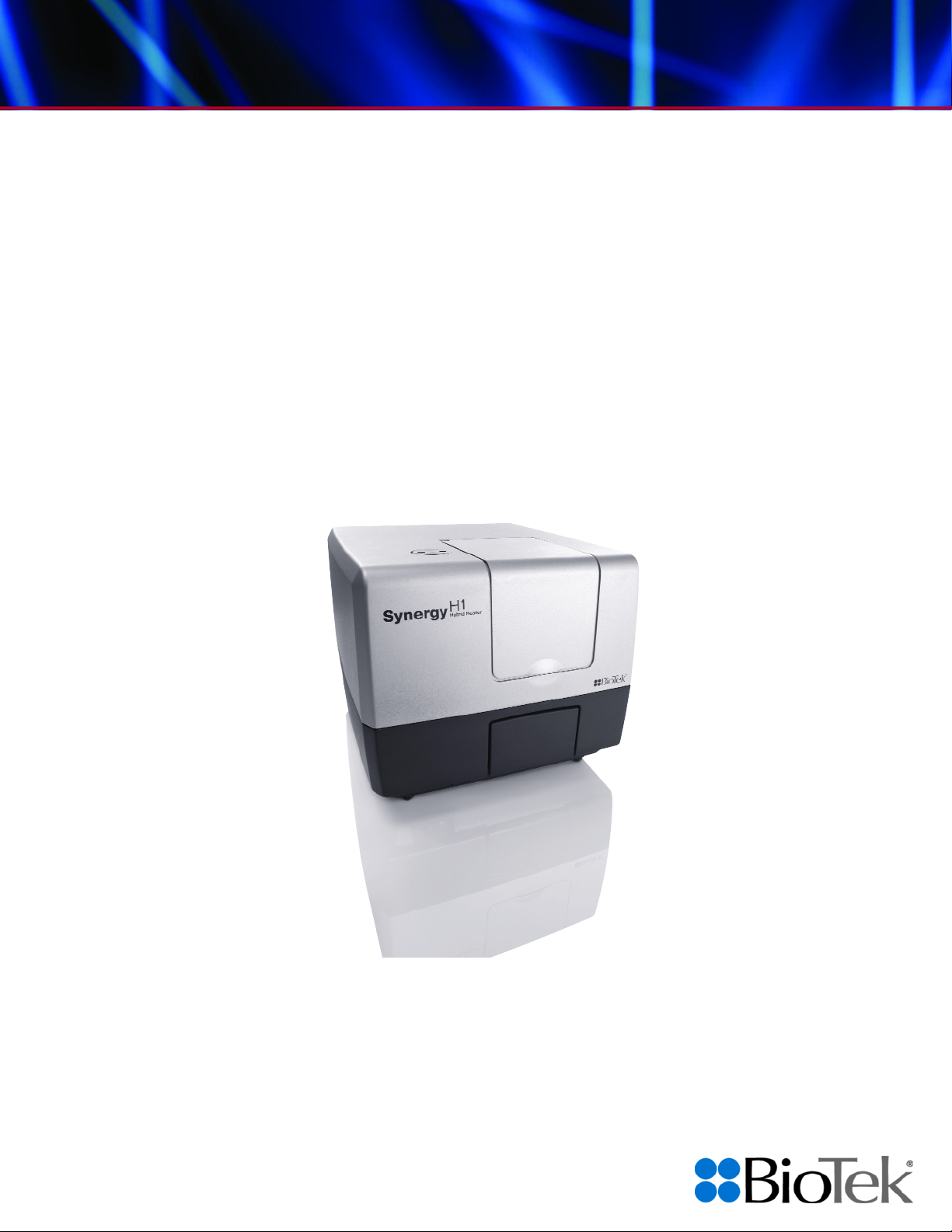
Synergy H1™
Hybrid Multi-Mode Microplate Reader
Operator’s Manual
March 2014
© 2014
Part Number 8041000
Revision G
BioTek® Instruments, Inc.
Page 4

ii | Notices
Notices
BioTek® Instruments, Inc.
Highland Park, P.O. Box 998
Winooski, Vermont 05404-0998 USA
All Rights Reserved
© 2014, BioTek® Instruments, Incorporated. No part of this publication may be
reproduced, transcribed, or transmitted in any form, or by any means electronic or
mechanical, including photocopying and recording, for any purpose other than the
purchaser’s use without written permission of BioTek Instruments, Inc.
Trademarks
BioTek® is a registered trademark, and Synergy™ H1, Gen5™, BioStack™, and
Take3™ and Take3Trio™ Micro-Volume Plates are trademarks of BioTek Instruments,
Inc. Harta™ is a trademark of Harta Instruments. Glowell™ is a trademark of LUX
Biotechnology, Ltd.
Microsoft
®
, Windows®, and Excel® are either registered trademarks or trademarks of
Microsoft Corporation in the United States and/or other countries.
®
Kalrez
is a registered trademark of DuPont Performance Elastomers, L.L.C. (DPE).
All other trademarks are the property of their respective holders.
Restrictions and Liabilities
Information in this document is subject to change and does not represent a
commitment by BioTek Instruments, Inc. Changes made to the information in this
document will be incorporated in new editions of the publication. No responsibility is
assumed by BioTek for the use or reliability of software or equipment that is not
supplied by BioTek or its affiliated dealers.
BioTek Instruments, Inc.
Page 5

Contents
Global Service and Support ................................................................ v
Revision History ............................................................................. vii
Document Conventions .................................................................... ix
Intended Use Statement .................................................................. ix
Quality Control ................................................................................ x
Warranty and Product Registration ..................................................... x
Repackaging and Shipping ................................................................. x
Warnings ........................................................................................ x
Hazards ......................................................................................... xi
Precautions ................................................................................... xii
CE Mark ....................................................................................... xiii
Electromagnetic Interference and Susceptibility ................................. xiv
User Safety ................................................................................... xv
Safety Symbols ............................................................................. xvi
Introduction ........................................................................................ 1
Product Description ......................................................................... 2
Package Contents & Accessories ........................................................ 3
Optional Accessories ........................................................................ 4
Product Support & Service ................................................................ 6
0BInstallation ......................................................................................... 7
Product Registration ........................................................................ 8
Important Information ..................................................................... 8
1: Unpack and Inspect the Reader ..................................................... 9
2: Unpack and Inspect the Dispense Module ...................................... 10
3: Unpack and Inspect the Gas Controller .......................................... 11
4: Select an Appropriate Location ..................................................... 11
5: Remove the Shipping Hardware .................................................... 12
6: Install the Power Supply .............................................................. 13
7: Connect the Gas Controller .......................................................... 13
8: Install the Dispense Module ......................................................... 13
9: Connect the Host Computer ......................................................... 17
10: Install Gen5 on the Host Computer ............................................. 18
11: Turn on the Reader ................................................................... 18
12: Establish Communication ........................................................... 18
13: Run a System Test ................................................................... 19
14: Test the Injector System ........................................................... 20
Operational/Performance Qualification ............................................... 22
Repackaging and Shipping Instructions ............................................. 22
Getting Started .................................................................................. 29
Modular Design .............................................................................. 30
External Components ...................................................................... 31
Internal Components ...................................................................... 31
Contents | iii
Synergy H1 Operator’s Manual
Page 6

iv | Contents
Gen5 Software ............................................................................... 36
Recommendations for Optimum Performance ..................................... 39
Filters and Mirrors ............................................................................. 43
Filter Cube Overview ...................................................................... 44
Filters and Mirrors .......................................................................... 48
Preventive Maintenance .................................................................... 53
Preventive Maintenance .................................................................. 54
Warnings and Precautions ............................................................... 55
Clean Exposed Surfaces .................................................................. 56
Inspect/Clean Excitation and Emission Filters ..................................... 57
Inspect/Clean Mirrors ..................................................................... 58
Flush/Purge the Fluid Path ............................................................... 60
Run a Dispense Protocol (Optional) ................................................... 61
Empty/Clean the Tip Priming Trough ................................................. 62
Clean the Priming Plate ................................................................... 62
Clean the Dispense Tubes and Injectors ............................................ 63
As-Needed Maintenance .................................................................... 65
Decontamination ............................................................................ 66
Dispense Module: Syringe Replacement ............................................. 72
0BInstrument Qualification ................................................................... 75
Overview ...................................................................................... 77
IQ/OQ/PQ ..................................................................................... 77
Recommended Qualification Schedule ............................................... 78
System Test .................................................................................. 79
Absorbance Plate Test ..................................................................... 85
Absorbance Liquid Tests .................................................................. 91
Fluorescence Liquid Tests ................................................................ 99
Luminescence Test ....................................................................... 122
Dispense Module Tests .................................................................. 129
Specifications .................................................................................. 141
General Specifications ................................................................... 142
Absorbance Specifications ............................................................. 144
Dispense/Read Specifications ......................................................... 145
Fluorescence Specifications (Mono-Based) ....................................... 145
Fluorescence Specifications (Filter-Based) ........................................ 146
Luminescence Specifications .......................................................... 147
Error Codes ..................................................................................... 149
Overview .................................................................................... 150
Error Codes ................................................................................. 151
Instrument Dimensions for Robotic Interface ................................. 155
BioTek Instruments, Inc.
Page 7

Global Service and Support | v
Mailing Address:
Winooski, VT 05404
Room 304, Tower D
Phone: (800) 242-4685
Phone: +86 (10) 85865569
Email: TAC@biotek.com
Website: www.biotek.com
Email: infochina@biotek.com
Website: www.biotekchina.com.cn
Kocherwaldstrasse 34 D-74177
Germany
50 avenue d'Alsace
France
Phone: +49 (0) 71369680
Fax: +49 (0) 7136968111
Phone: +33 (3) 89206329
Fax: +33 (3) 89204379
Email: info@biotek.de
Website: www.biotek.de
Email: info@biotek.fr
Website: www.biotek.fr
BioTek India
BioTek Singapore
Unit 223, Linkway Estate
India
20 Science Park Road #01-08A
Phone: +91 (22) 28789966
Fax: +91 (22) 28759944
Phone: +65 65922100
Fax: +65 67772611
Email: biotek@biotek.in
Website: www.biotek.in
Email: singapore@biotek.com
Website: www.biotek.com
Global Service and Support
See also Product Support & Service on page 6.
BioTek instrument service and repair is available worldwide at one of BioTek's
International Service Centers and in the field at your location. For technical assistance,
contact the Technical Assistance Center (TAC) at BioTek World Headquarters US. To
arrange for service or repair of your instrument, contact the office nearest you.
BioTek World Headquarters US BioTek China
PO Box 998, Highland Park
Winooski, VT 05404-0998
United States
Service Shipping Address:
15 Tigan Street
Outside US: (802) 655-4740
Fax: (802) 654-0638
BioTek Germany Service Center &
European Coordination Center
Bad Friedrichshall
Ocean International Center
62 Middle 4th East Ring Road
Chaoyang District
Beijing 100025
P.R. China
Fax: +86 (10) 85861829
BioTek Instruments SAS
Bureau de liaison France
68025 Colmar Cedex
New Link Road, Malad West
Mumbai 400064
Synergy H1 Operator’s Manual
Teletech Park
Singapore 117674
Page 8

vi | Global Service and Support
3F, Gyungnam building, 830-48
Seoul, South Korea (135-936)
Zentrum Fanhöfli 8
Switzerland
Phone: +82 (0) 2-562-4740
Fax: +82 (0) 2-562-4750
Phone: +41 (41) 2504060
Fax: +41 (41) 2505064
Email: korea@biotek.com
Website: www.biotekinstruments.co.kr
Email: info@biotek.ch
Website: www.biotek.ch
6 Bull Street
United Kingdom
Phone: +44 (1767) 262000
Fax: +44 (1767) 262330
Email: info@biotek.uk.com
Website: www.biotek.uk.com
BioTek South Korea BioTek Switzerland
Yeoksam-dong, Gangnam-gu
BioTek United Kingdom (UK)
Potton, Bedfordshire SG19 2NR
6014 Luzern
BioTek Instruments, Inc.
Page 9

Revision History | vii
Chapter 1, Introduction: Added information about the incubation
Revision History
Rev Date Changes
A 11/10 Initial release
B 8/11
C 11/11
D 5/12
E 9/12 Preface: Added EN 61010-2-010 to Directive 2006/95/EC.
F 10/13 Preface: Updated contact information to include global information.
General: Updated instructions for new Gen5 version 2.x. Updated
Absorbance Plate Test information.
Preface: Updated Intended Use Statement.
Chapter 1: Introduction: Updated Package Contents to remove
wrench, plugs, clip, and storage bag; added screwdriver. Added
Take3Trio Micro-Volume plate to list of supported plates and
Optional Accessories. Updated Solutions for Liquid Tests in Optional
Accessories.
Chapter 4: Filter and Mirrors: Figure 2, corrected the caption by
reversing the “EM” and “EX” filter designations.
Chapter 7: Instrument Qualification: Updated Absorbance Plate Test
definition instructions to support the Erbium glass filter in location
C6. Updated Fluorescence Liquid Test information to include preconfigured TRF filter cube.
Appendix A: Specifications: Corrected Incubation specification.
Chapter 2: Installation: Updated the Carrier Shipping Bracket photo
in Figure 1. Updated the BioTek part number for the shipping
hardware. Updated the Dispense Module installation instructions.
Chapter 7: Instrument Qualification: For the Absorbance Plate Test,
removed the restriction on the use of the peak closest to 243 nm for
the Erbium glass (any peak may be used). In the Fluorescence
Liquid Tests section, for the Corners/Sensitivity/Linearity tests,
added information on Sodium Fluorescein Kit, BioTek PN 7160013.
Chapter 9: Specifications: Clarified the test methods used for
Absorbance performance and incubation temperature.
Preface: Updated the Intended Use Statement and the heading for
the In Vitro Diagnostics directive to refer to the instrument’s IVD
label (if one exists). Added ‘Service’ and ‘Accessories’ hazard
warnings. Added ‘Spare Parts’ precaution. Added warning to have
two people lift and carry the instrument.
Chapter 1, Introduction: Corrected the power supply part number.
Added support for the gas controller.
Chapter 3, Getting Started: Added gas controller modules. Updated
the chemical compatibility table for the dispense module.
Appendix B, Error Codes: Added new information to the “Description
and Possible Remedy” sections for several codes.
Section 1, Introduction: Added information on patent for dual light
path capability.
Appendix A, Specifications: Updated flash lamp specifications.
Synergy H1 Operator’s Manual
Page 10

viii | Revision History
gradient.
Chapter 3, Getting Started: Added the workarounds for kinetic
assays with continuous shake.
Chapter 4, Filters and Mirrors: Added a note that the polarizer filters
are keyed to fit in the correct alignment in the filter cube.
Chapter 7, Instrument Qualification: Added “filter-based” to TRF
descriptions.
Appendix A, Specifications: Added information about the incubation
gradient.
G 3/2014
Chapter 4, Filters and Mirrors: Add photos to procedure for installing
the filter cube; added a table of mirrors with their wavelength
ranges.
BioTek Instruments, Inc.
Page 11

Document Conventions
See also Safety Symbols on page xvi.
This icon calls attention to important safety notes.
Document Conventions | ix
Warning!
Caution
Note:
italic
A Warning indicates the potential for bodily harm and
tells you how to avoid the problem.
A Caution indicates potential damage to the instrument
and tells you how to avoid the problem.
Bold text is primarily used for emphasis.
Topics that apply only to specific Synergy H1 models are
preceded by a notice in italics, for example: Applies only to
Synergy H1 models with injectors.
This icon calls attention to important information.
Intended Use Statement
• The Synergy H1 is a hybrid multi-mode microplate reader. The performance
characteristics of the data reduction software have not been established with any
laboratory diagnostic assay. The user must evaluate this instrument and PC-based
software in conjunction with their specific assay(s). This evaluation must include
the confirmation that performance characteristics for the specific assay(s) are met.
• If the instrument has an “IVD” label it may be used for clinical and non-clinical
purposes, including research & development. If there is no such label the
instrument may only be used for research and development or other non-clinical
purposes.
Synergy H1 Operator’s Manual
Page 12

x | Quality Control
Precautions.
Quality Control
It is considered good laboratory practice to run laboratory samples according to
instructions and specific recommendations included in the assay package insert for the test
to be conducted. Failure to conduct Quality Control checks could result in erroneous test
data.
Warranty and Product Registration
Take a moment to review the warranty information that shipped with your product.
Please also register your product with BioTek to ensure that you receive important
information and updates about the product(s) you have purchased. You can register online
through the Customer Resource Center (CRC) at www.biotek.com or by calling 888-4515171 or 802-655-4740.
Repackaging and Shipping
If you need to ship the instrument to BioTek for service or repair,
contact BioTek for a Return Materials Authorization (RMA)
number, and be sure to use the original packing materials. Other
forms of commercially available packaging are not recommended
and can void the warranty. If the original packing materials have
been damaged or lost, contact BioTek for replacement packing.
Warnings
Operate the instrument on a level, stable surface away from excessive humidity.
Bright sunlight or strong incandescent light can reduce the linear performance
range of the instrument.
Measurement values may be affected by extraneous particles (such as dust) in the
microplate wells. A clean work area is necessary to ensure accurate readings.
When operated in a safe environment according to the instructions in this
document, there are no known hazards associated with the instrument. However,
the operator should be aware of certain situations that could result in serious
injury; these may vary depending on the instrument type. See
Hazards and
BioTek Instruments, Inc.
Page 13

Hazards
Warning! Internal Voltage. Always turn off the power switch and unplug the
case.
shock and fire hazards.
appropriate receptacle with a functional ground.
procedures on internal components.
shall be used with the instrument.
kg). Use two people when lifting and carrying the instrument.
components have been exposed to fluid. Contact BioTek TAC for assistance.
condition.
data.
analyzed by the operator.
appropriate protective equipment, such as chemical-resistant rubber gloves and apron.
The following hazard warnings are provided to help avoid injury:
power supply before cleaning the outer surface of the instrument or removing its top
Warning! Power Rating. The instrument’s power supply or power cord must be
connected to a power receptacle that provides voltage and current within the specified
rating for the system. Use of an incompatible power receptacle may produce electrical
Hazards | xi
Warning! Electrical Grounding. Never use a plug adapter to connect primary
power to the external power supply. Use of an adapter disconnects the utility ground,
creating a severe shock hazard. Always connect the power cord directly to an
Warning! Service. Only qualified technical personnel should perform service
Warning! Accessories. Only accessories that meet the manufacturer’s specifications
Warning! The instrument with all available modules weighs up to 55 pounds (24.95
Warning! Liquids. Avoid spilling liquids on the instrument; fluid seepage into
internal components creates a potential for shock hazard or instrument damage.
If a spill occurs while a program is running, abort the program and turn the instrument
off. Wipe up all spills immediately. Do not operate the instrument if internal
Warning! Unspecified Use. Failure to operate the equipment according to the
guidelines and safeguards specified in this manual could result in a hazardous
Warning! Software Quality Control. The operator must follow the manufacturer’s
assay package insert when modifying software parameters and establishing reading
methods. Failure to conduct quality control checks could result in erroneous test
Warning! Reader Data Reduction Protocol. No limits are applied to the raw
measurement data. All information exported via computer control must be thoroughly
Warning! Potential Biohazards. Some assays or specimens may pose a biohazard.
This hazard is noted by the symbol shown here. Adequate safety precautions should be
taken as outlined in the assay’s package insert. Always wear safety glasses and
Synergy H1 Operator’s Manual
Page 14

xii | Precautions
operating.
service procedures on internal components.
potentially impair instrument performance or cause damage to the instrument
broader. .
thoroughly wipe all surfaces.
within the range of line voltages listed on it.
electrical and electronic equipment (WEEE)” or local ordinances.
the warranty.
reinstalled before repackaging the instrument for shipment.
intended.
because these may interfere with the proper operation.
Warning! Pinch Hazard. Some areas of the dispense module can present pinch
hazards when the instrument is operating. The module is marked with one of the
symbols shown here. Keep hands/fingers clear of these areas when the instrument is
Precautions
The following precautions are provided to help avoid damage to the instrument:
Caution: Service. The instrument should be serviced by BioTek-authorized
personnel. Only qualified technical personnel should perform troubleshooting and
Caution: Spare Parts. Only approved spare parts should be used for maintenance.
The use of unapproved spare parts and accessories may result in a loss of warranty and
Caution: Environmental Conditions. Do not expose the system to temperature
extremes. For proper operation, ambient temperatures should remain within the range
listed in the
temperatures fluctuate above or below this range. Storage temperature limits are
Specifications section. Performance may be adversely affected if
Caution: Sodium Hypochlorite. Do not expose any part of the instrument to the
recommended diluted sodium hypochlorite solution (bleach) for more than 20 minutes.
Prolonged contact may damage the instrument surfaces. Be certain to rinse and
Caution: Power Supply. Use only the power supply shipped with the instrument
Caution: Disposal. This instrument contains printed circuit boards and wiring with
lead solder. Dispose of the instrument according to Directive 2002/96/EC, “on waste
Caution: Warranty. Failure to follow preventive maintenance procedures may void
Caution: Shipping Hardware. All shipping hardware (e.g., carrier shipping screw,
filter reader shipping bracket) must be removed before operating the instrument and
Caution: Electromagnetic Environment. Per EN 61326-2-6 it is the user’s
responsibility to ensure that a compatible electromagnetic environment for this
instrument is provided and maintained in order that the device will perform as
Caution: Electromagnetic Compatibility. Do not use this device in close proximity
to sources of strong electromagnetic radiation (e.g., unshielded intentional RF sources),
BioTek Instruments, Inc.
Page 15

CE Mark
Based on the testing described below and information
contained herein, this instrument bears the CE mark.
See the Declaration of Conformity for more specific information.
Directive 2004/108/EC: Electromagnetic Compatibility
Emissions—CLASS A
The system has been type-tested by an independent, accredited testing laboratory
and found to meet the requirements of EN 61326-1: Class A for Radiated Emissions
and Line Conducted Emissions.
Verification of compliance was conducted to the limits and methods of EN 55011–
(CISPR 11) Class A. In a domestic environment it may cause radio interference, in
which case you may need to mitigate the interference.
CE Mark | xiii
Immunity
The system has been type-tested by an independent, accredited testing laboratory
and found to meet the requirements of EN 61326-1 and EN 61326-2-6 for Immunity.
Verification of compliance was conducted to the limits and methods of the
following:
EN 61000-4-2, Electrostatic Discharge
EN 61000-4-3, Radiated EM Fields
EN 61000-4-4, Electrical Fast Transient/Burst
EN 61000-4-5, Surge Immunity
EN 61000-4-6, Conducted Disturbances from RFI
EN 61000-4-11, Voltage Dips, Short Interruptions and Variations
Directive 2006/95/EC Low Voltage (Safety)
The system has been type-tested by an independent testing laboratory and was found
to meet the requirements of this Directive. Verification of compliance was conducted to
the limits and methods of the following:
EN 61010-1, “Safety requirement for electrical equipment for measurement, control and
laboratory use. Part 1, General requirements.”
EN 61010-2-081, “Requirements for automatic and semi-automatic laboratory
equipment for analysis and other purposes.”
EN 61010-2-010, “Particular requirements for laboratory equipment for the heating of
materials.”
Synergy H1 Operator’s Manual
Page 16

xiv | Electromagnetic Interference and Susceptibility
Directive 2002/96/EC: Waste Electrical and Electronic Equipment
Disposal Notice: This instrument contains printed circuit boards and wiring with lead
solder. Dispose of the instrument according to Directive 2002/96/EC, “on waste
electrical and electronic equipment (WEEE)” or local ordinances.
Directive 98/79/EC: In Vitro Diagnostics (if labeled for this use)
• Product registration with competent authorities
• Traceability to the U.S. National Institute of Standards and Technology (NIST).
• EN 61010-2-101, “Particular requirements for in vitro diagnostic (IVD) medical
equipment.”
Electromagnetic Interference and Susceptibility
USA FCC CLASS A
RADIO AND TELEVISION INTERFERENCE
NOTE: This equipment has been tested and found to comply with the limits for a Class
A digital device, pursuant to Part 15 of the FCC Rules. These limits are designed to
provide reasonable protection against harmful interference when the equipment is
operated in a commercial environment. This equipment generates, uses, and can
radiate radio frequency energy and, if not installed and used in accordance with the
instruction manual, may cause harmful interference to radio communications.
Operation of this equipment in a residential area is likely to cause harmful interference,
in which case the user will be required to correct the interference at their own expense.
In order to maintain compliance with FCC regulations shielded cables must be used
with this equipment. Operation with non-approved equipment or unshielded cables is
likely to result in interference to radio and television reception.
Canadian Department of Communications Class A
This digital apparatus does not exceed Class A limits for radio emissions from digital
apparatus set out in the Radio Interference Regulations of the Canadian Department of
Communications.
Le present appareil numerique n'émet pas de bruits radioélectriques depassant les
limites applicables aux appareils numérique de la Class A prescrites dans le Réglement
sur le brouillage radioélectrique édicté par le ministère des Communications du
Canada.
BioTek Instruments, Inc.
Page 17

User Safety
This device has been type-tested by an independent laboratory and found to meet the
requirements of the following:
• Underwriters Laboratories UL 61010-1, “Safety requirements for electrical
equipment for measurement, control and laboratory use; Part 1: general
requirements.”
• Canadian Standards Association CAN/CSA C22.2 No. 61010-1, “Safety
requirements for electrical equipment for measurement, control and laboratory
use; Part 1: general requirements.”
User Safety | xv
• EN 61010 standards, see
CE Mark starting on page xiii.
Synergy H1 Operator’s Manual
Page 18

xvi | Safety Symbols
Safety Symbols
Some of these symbols may appear on the instrument or accessories:
Alternating current
Courant alternatif
Wechselstrom
Corriente alterna
Corrente alternata
Direct current
Courant continu
Gleichstrom
Corriente continua
Corrente continua
On (Supply)
Marche (alimentation)
Ein (Verbindung mit dem Netz)
Conectado
Chiuso
Off (Supply)
Arrêt (alimentation)
Aus (Trennung vom Netz)
Desconectado
Aperto (sconnessione dalla
rete di alimentazione)
Both direct and alternating current
Courant continu et courant alternatif
Gleich - und Wechselstrom
Corriente continua y corriente alterna
Corrente continua e corrente alternata
Earth ground terminal
Borne de terre
Erde (Betriebserde)
Borne de tierra
Terra (di funzionamento)
Protective conductor terminal
Borne de terre de protection
Schutzleiteranschluss
Borne de tierra de protección
Terra di protezione
Caution (refer to accompanying documents)
Attention (voir documents
d’accompanement)
Achtung siehe Begleitpapiere
Atención (vease los documentos incluidos)
Attenzione, consultare la doc annessa
Warning, risk of electric shock
Attention, risque de choc
électrique
Gefährliche elektrische schlag
Precaución, riesgo de sacudida
eléctrica
Attenzione, rischio di scossa
elettrica
Warning, hot surface
Attention, surface chaude
Warnen, heiße Oberfläche
Precaución, superficie caliente
Attenzione, superficie calda
Warning, risk of crushing or pinching
Attention, risque d’écrasement et
pincement
Warnen, Gefahr des Zerquetschens und
Klemmen
Precaución, riesgo del machacamiento y
sejeción
Attenzione, rischio di schiacciare ed
intrappolarsi
Warning, potential biohazards
Attention, risques biologiques potentiels
Warnung! Moegliche biologische Giftstoffe
Atención, riesgos biológicos
Attenzione, rischio biologico
BioTek Instruments, Inc.
Page 19

Safety Symbols | xvii
In vitro diagnostic medical
device
Dispositif médical de
diagnostic in vitro
Medizinisches In-VitroDiagnostikum
Dispositivo médico de
diagnóstico in vitro
Dispositivo medico diagnostico
in vitro
Consult instructions for use
Consulter la notice d’emploi
Gebrauchsanweisung beachten
Consultar las instrucciones de
uso
Consultare le istruzioni per uso
Separate collection for electrical and
electronic equipment
Les équipements électriques et
électroniques font l’objet d’une collecte
sélective
Getrennte Sammlung von Elektro- und
Elektronikgeräten
Recogida selectiva de aparatos eléctricos y
electrónicos
Raccolta separata delle apparecchiature
elettriche ed elettroniche
Laser radiation: Do not stare into beam
Rayonnement laser: Ne pas regarder dans
le faisceau
Laserstrahlung: Nicht in den strahl blicken
Radiación de láser: No mire fijamente al
rayo
Radiazione di laser: Non stare nel fascio
Synergy H1 Operator’s Manual
 Loading...