

Page 1
Operator’s Manual
Microplate Spectrophotometer
PowerWave
™
Page 2

Page 3

TM
PowerWave
Microplate Spect rophotometer
Operator's Manual
June 2011
© 2011
Part Number 7281000
Revision F
BioTek® Instruments, Inc.
Page 4

2 | Preface
Notices
BioTek® Instruments, Inc.
Highland Park, P.O. Box 998
Winooski, Vermont 05404-0998 USA
All Rights Reserved
© 2011, BioTek® Instruments, Incorporated. No part of this publication may be
reproduced, transcribed, or transmitted in any form, or by any means electronic or
mechanical, including photocopying and recording, for any purpose other than the
purchaser’s use without written permission of BioTek Instruments, Inc.
Trademarks
BioTek® is a registered trademark, and PowerWave™, Gen5™, 4-Zone™ and
BioStack™ are trademarks of BioTek Instruments, Inc. BioCell™ is a trademark of
BioTek Instruments and is patented under U.S. patent number 5,963,318.
Microsoft®, and Windows®, are either registered trademarks or trademarks of
Microsoft Corporation in the United States and/or other countries.
All other trademarks are the property of their respective holders.
Restrictions and Liabilities
Information in this document is subject to change and does not represent a
commitment by BioTek Instruments, Inc. Changes made to the information in this
document will be incorporated in new editions of the publication. No responsibility is
assumed by BioTek for the use or reliability of software or equipment that is not
supplied by BioTek or its affiliated dealers.
BioTek Instruments, Inc.
Page 5

Contents
Preface ........................................................................................... 2
Notices ....................................................................................... 2
Contents ..................................................................................... 3
Contact Informat i on ..................................................................... 5
Revision History ........................................................................... 6
Document Conventions ................................................................. 8
Intended Use Statement ............................................................... 8
Quality Control ............................................................................. 9
Warranty and Product Registration ................................................. 9
Repackaging and Shipping ............................................................. 9
Warnings .................................................................................... 9
Hazards .................................................................................... 10
Precautions ............................................................................... 11
CE Mark .................................................................................... 12
Electromagnetic Interference and Sus ceptibility ............................. 13
User Safety ............................................................................... 14
Safety Symbols .......................................................................... 15
Chaper 1: Introduction ................................................................. 17
Product Description ....................................................................
Package Contents ....................................................................... 18
Optional Accessories ................................................................... 19
Specifications ............................................................................ 20
Product Support & Service ........................................................... 23
Contents | 3
All Rights Reserved.................................................................. 2
Trademarks ............................................................................ 2
Restrictions and Liabilities ........................................................ 2
Customer Service and Sales ..................................................... 5
Service/TAC ........................................................................... 5
European Coordination Center/Authorized European Representative5
Directive 2004/108/EC: Electromagnetic Compatibility ............... 12
Directive 73/23/EEC Low Voltage (Safety) ................................ 12
Directive 2002/96/EC: Waste Electrical and Electronic Equipment 12
Directive 98/79/EC: In Vitro Diagnostics .................................. 13
USA FCC CLASS A ................................................................. 13
Canadian Department of Communications Class A ..................... 13
18
Microplates ........................................................................... 20
Speed of Reading .................................................................. 20
Optical Specifications ............................................................. 21
Optical Performance .............................................................. 21
Hardware and Enviro nmental S pecifications .............................. 22
Contacting the Technical Assistance Center .............................. 23
Returning Instruments for Service/Repair ................................. 23
PowerWave Operator’s Manual
Page 6

4 | Preface
Chapter 2: Installation ................................................................. 25
Product Registration ................................................................... 26
1: Unpack and Inspect the Instrument .......................................... 26
2: Remove the Carrier Shipping Bracket........................................ 26
3: Select an Appropriate Location ................................................. 27
4: Connect the Power Supply ....................................................... 28
5: Connect the Host Computer ..................................................... 29
6: Install Gen5 ........................................................................... 29
7: Turn on the Reader ................................................................ 29
Operational/Performance Qua lification .......................................... 30
Repackaging and Shipping Instructions ......................................... 31
Chapter 3: Operation .................................................................... 35
Operating the PowerWave ........................................................... 36
Getting Started with Gen5 ........................................................... 36
Recommendations for Optimum Performance................................. 37
Where to Go Next ...................................................................... 38
Chapter 4: Instrument Qualification ............................................. 39
Overview................................................................................... 40
Recommended Qualification Schedule ........................................... 40
Qualification Procedures .............................................................. 41
System Test .............................................................................. 41
Sample System Test Report.................................................... 42
Absorbance Plate Test ................................................................. 44
Test Plate and Certificates ...................................................... 44
Enter the Absorbance Test Plate Data ...................................... 44
Run the Absorbance Plate Test ................................................ 44
Sample Absorbance Plate Test Report ...................................... 45
Test Results .......................................................................... 46
Liquid Testing ............................................................................ 47
Absorbance Liquid Test 1 ....................................................... 48
Absorbance Liquid Test 2 .......................................................
50
Absorbance Liquid Test 3 (Optional) ........................................ 53
Chapter 5: Decontamination ......................................................... 57
Purpose .................................................................................... 58
Clean Plate Carrier and Exposed Surfaces ...................................... 59
Decontamination ........................................................................ 60
Tools and Supplies ................................................................ 60
Chapter 6: Troubleshooting .......................................................... 61
Error Codes ............................................................................... 62
Error Codes During Operation with the BioStack ........................ 62
General Errors ........................................................................... 63
Fatal Errors ............................................................................... 67
Chapter 7: Instrument Dimensions .............................................. 69
Instrument Dimensio ns ............................................................... 70
BioTek Instruments, Inc.
Page 7

Internet:
www.biotek.com
Phone:
888-451-5171 (toll free in the U.S.)
802-655-4740 (outside the U.S.)
Fax:
802-655-7941
E-Mail:
customercare@biotek.com
Phone:
800-242-4685 (toll free in the U.S.)
802-655-4740 (outside the U.S.)
Fax:
802-654-0638
E-Mail:
tac@biotek.com
Internet:
www.biotek.de
Phone:
+49 (0) 7136 9680
Fax:
+49 (0) 7136 968 111
E-Mail:
info@biotek.de
Contact Information
BioTek® Instruments, Inc.
Highland Park, P.O. Box 998
Winooski, Vermont 05404-0998 USA
Customer Service and Sales
Contact Inform ation | 5
Service/TAC
European Coordination Center/Authorized European
Representative
BioTek® Instruments GmbH
Kocherwaldstrasse 34
D-74177 Bad Friedrichshall
Germany
PowerWave Operator’s Manual
Page 8

6 | Preface
Microplate Stacker,’and ‘Abs’ to ‘OD’. Removed ‘Scanning’ from ‘PowerWave™
Revision History
Revision Date Changes
A 12/2001 First issue.
B 2/2002 For the Optical Perf or mance Specific a tions, changed the maximum allowa ble
Gain on Optics from 6.0 to 10.0 (page 1-5).
Replaced Figures 3-1a and 3-1b, Sample Output for the System Test (pages
3-4 and 3-5).
Updated technical support contact information (pages iii, 1-6, and 1-7).
Made editorial changes.
C 8/2003 Updated TAC information in Preface and Ch. 1, and Customer Servic e a nd
European contact information, Hazards, Standards, Safety Symbols, Intended
Use Statement, and Warranty in Preface.
Updated Introduction, Variations, Hardware Features, Software Features,
Package Contents, Optional Accessories, and Specifications, Ch. 1.
Enhanced Unpackin g/ R epack a ging sections, Ch. 2; added Fig. 2-5, 2-6.
Revised Ch. 3 se c tions: System Test, Universal Plate Test, Liquid Testing.
Enhanced Decontaminatio n section; added Cleaning section in App. A.
Enhanced section on KC4™ , added section on KCjunior™ in App. B, and
replaced previou s s e r ia l control section w ith a reference to Bio-Tek’s serial
communication pr otocol specifica tion 7266201-SP.
Replaced Error Codes tables in App. C with more detailed tables from the
PowerWave™ HT Service Manual.
Added information about t he optional barcode scanner in Ch. 1, and added
new App. E, Barcode Scanner .
Referenced new version s of PowerWave™, PowerWave™ 340, a nd
PowerWave™ HT 340 through out manual.
Included refer e nces to KCjunior as a n additional primary operating software
and substitute for KC4.
Included information about the compa tibility of the Power Wave with the BioStack™ Automated Microplate Stacking System, and brief paragraphs
concerning ins tallation, serial cab le connections, er r or codes, and align ment
when operating the PowerWave with the Bio-Stack; referenced the Bio Stack
Operator’s Manual.
D 5/2006 Updated prim arily to support introduction of Gen5™ Software.
General: Added Gen5 referen c es a nd instructions wherever KC4™ and
KCjunior™ references a nd instructions were present. Changed ‘Bio-Tek’ to
‘BioTek,’ ‘Bio-Stack™ Automated Microplate S tacking System’ to ‘Bio-Stack
Microplate Scanning Spectrophot om e ter’.
Cover: Replaced existing c ov er with new design.
BioTek Instruments, Inc.
Page 9

Revision Date Changes
Throughout: Removed references to models ‘PowerWav e’ a nd ‘PowerWave HT
General: Removed references to outdated software KC4 and KCjunior.
(D) Preface: Updated contact information, Warnings, Hazards, Pre-cautions,
Safety Symbols. Removed Warranty and Registration Card.
Chapter 1, Introduction: Added clarification (in Inte r nal Barcode Scann er
section) that some older models of the reader may include the scanner.
Updated Package Conten ts, Optional Accessories, and replac ed pr ev ious
Technical Support pages w ith a P r oduct Support and Service page.
Chapter 2, Insta llation: Rearran ged installation steps to better reflect actu a l
practice.
Chapter 3, Performance Verificati on/Qualification T es ts : Added Gen5™
instructions for the Self Test and Absorbance Plate Test. In Recommended
Qualification Schedule, moved Absorbance Plate Test and Liquid Tests from
IQ to initial/ann ual OQ, changed PQ sem ia nnual frequency to quarterly, and
clarified criteria for running Liquid Tests 1, 2, or 3. Changed ‘Universal’ to
‘Absorbance’ in ‘Universal Test Pla te’ and ‘Universa l Plate Test’. In Liquid
Test 1, added BioTek wetting agent (7773002) to list of ingr edien ts . In Liquid
Test 3, changed Sigma® ‘P 3563 pac kets’ to ‘PBS tablets (#4417, or
equivalent).’ In Liqu id T es ts 1 a nd 3, changed ‘Analytical balance’ to
‘Precision balan ce.’ In all Liquid T ests, added ‘Cornin g” to “Costar’
(microplates), and added n ote to sh a ke plate or wait after pipetting and
before reading the plate.
Appendix A, Decontamination and C leaning: Corrected dilu tion mixtures for
bleach on page A-3 by changin g ‘ 20: 1’ r a tio f or c ommercial bleach to ‘1:20’,
and ‘10:1’ ratio for househ old bleach to ‘1:10’.
Appendix B, Computer Control: Added n ew section, “Controlling the Reader
with Gen5.”
E 12/2009
340’ (PowerWave HT and PowerW a ve 340 remain). Emphasized use of Gen5
instead of KC4 an d K Cjunior (which are no longer available fr om BioTek).
Removed references to the A c tiv eX component.
Preface: Updated Tradema r ks, Intended Use Statement, H azards,
Precautions, CE Mark information, and Safety Symbols. Removed lists of
illustrations and tables.
Ch 1 Introduction : Removed ‘Variations’ and ‘Internal Barcode Scanner’.
Updated Package Contents and Optional Accessories.
Ch 2 Installation: Simplified unpacking and setup ins tru c tions. Removed
Serial Pinout Desc r iption.
Ch 3 Operation: New chapter.
Ch 4 Instrument Q ualification: Moved recommendations for optimum
performance to ne w chapter 3. Clarif ie d instructions for the various
qualification tasks.
F 5/2011
Former Appendix B, Computer Control: Deleted this section . Moved Gen5
instructions to n ew chapter 3.
Former Appendices A and C: Ch a nged to Chapters 5 and 6.
Former Appendices D and E: Ch a nged to Appendices A and B.
Updated Gen5 ins tr uctions for Gen5 version 2.x.
Introduction: Deleted redundant “Hardware Features” and “Softwa re
Features” sections.
Liquid Testing: Updated Liquid Test 3; remov ed in s tructions for creating the
10x concentration PBS solution.
Appendices: Removed former Appendix B: Barcode Scanner .
Revision History | 7
PowerWave Operator’s Manual
Page 10
8 | Preface
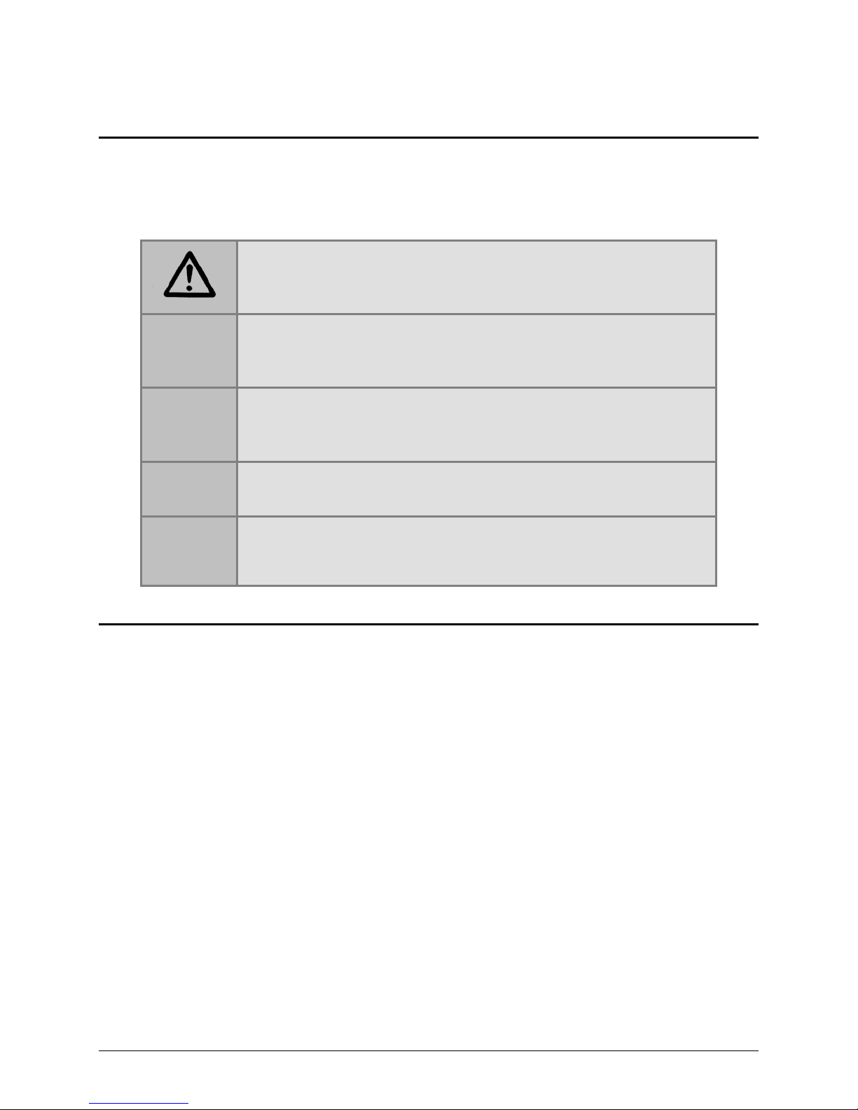
Document Conventions
This manual uses the following typographic conventions:
This icon calls attention to important safety notes.
Warning!
Caution
Note:
A Warning indicates the potential for bodily harm and
tells you how to avoid the problem.
A Caution indicates potential damage to the instrument
and tells you how to avoid the problem.
Bold text is primarily used for emphasis.
This icon calls attention to important inform ation.
Intended Use Statement
The PowerWave is an eight-channel, automated, benchtop, general-purpose Microplate
Spectrophotometer that performs optical density measurements of samples in a microplate
format. The user must evaluate this instrument with PC-based software in conjunction
with the specific assay. This evaluation must include the confirmation that performance
characteristics for the specific assay are met.
• BioTek Gen5 software package provides the user with instrument control and data
reduction capabilities.
• This product can operate with standard robotic systems, such as the BioStack
Microplate Stacker.
• This product may be used for In Vitro Diagnostic, research and development, or
other non-clinical purposes.
BioTek Instruments, Inc.
Page 11

Quality Control | 9
Operate the instrument on a level surface away from excessive humidity.
Quality Control
It is considered good laboratory practice to run laboratory samples according to
instructions and specific recommendations included in the package insert or standard
laboratory protocol for the test to be conducted. Failure to conduct Quality Control checks
could result in erroneous test data.
Warranty and Product Regist rat ion
Review the Warranty information that shipped with your product. Register your
product(s) with BioTek to ensure that you receive important information and updates.
Contact the Customer Resource Center (CRC) at www.biotek.com or by calling 888/4515171 or 802/655-4740.
Repackaging and Shipping
If you need to ship the instrument to BioTek for service or
repair, contact BioTek for a Return Materials Authorization
(RMA) number, and be sure to use the original packing
materials. Other forms of commercially available packaging are
not recommended and can void the warranty. If the original
packing materials have been damaged or lost, contact BioTek for
replacement packing.
Warnings
Strong light can reduce the linear performance range of the instrument.
Measurement values may be affected by extraneous particles (such as dust) in the
microplate wells. A clean work area is necessary to ensure accurate readings.
When operated in a safe environment according to the instructions in this
document, there are no known hazards associated with the instrument. However,
the operator should be aware of certain situations that could result in serious injury;
these may vary depending on the instrument model. See Hazards and Precautions.
PowerWave Operator’s Manual
Page 12

10 | Preface
Warning! Power Rating. The instrument’s power supply cord must be connected
Warning! Internal Voltage. Always turn off the power switch and unplug the
Warning! Potential Biohazards. Some assays or specimens may pose a
Hazards
The following hazard warnings are provided to help avoid injury:
to a power receptacle that provides voltage and current within the specified rating
for the system. Use of an incompatible power receptacle may produce electrical
shock and fire hazards.
Warning! Electrical Grounding. Never use a two-prong plug adapter to connect
primary power to the external power supply. Use of an adapter disconnects the
utility ground, creating a severe shock hazard. Always connect the power supply
directly to an appropriate receptacle with a functional ground.
power supply before cleaning the outer surface of the instrument.
Warning! Liquids. Avoid spilling liquids on the reader; fluid seepage into internal
components creates a potential for shock hazard or instrument damage. If a spill
occurs while a program is running, abort the program and turn off the instrument.
Wipe up all spills immediately. Do not operate the instrument if internal
components have been exposed to fluid.
Warning! Unspecified Use. Failure to operate this equipment according to the
guidelines and safeguards specified in this manual could result in a hazardous
condition.
Warning! Software Quality Control. The operator must follow the
manufacturer’s assay package insert when modifying software parameters and
establishing reading methods. Failure to conduct quality control checks could result
in erroneous test data.
Warning! Reader Data Reduction Protocol. No limits are applied to the raw
absorbance data. All information exported via computer control must be thoroughly
analyzed by the operator.
biohazard. Adequate safety precautions should be taken as outlined in the assay’s
package insert. Always wear safety glasses and appropriate protective equipment,
such as chemically resistant rubber gloves and an apron.
BioTek Instruments, Inc.
Page 13

Precautions
Caution: Ser v ic e. The instrument should be serviced by BioTek authorized service
Caution: Carrier Shipping Bracket. The microplate carrier shipping bracket
The following precautions are provided to help avoid damage to the instrument:
personnel. Only qualified technical personnel should perform troubleshooting and
service procedures on internal components.
Caution: Environmental Conditions. Do not expose the system to temperature
extremes. For proper operation, ambient temperatures should remain within the
range listed in the Specifications section of Chapter 1. Performance may be
adversely affected if temperatures fluctuate above or below this range. Storage
temperature limits are broader.
Caution: Sodium Hypochlorite. Do not expose any part of the instrument to the
recommended diluted sodium hypochlorite solution (bleach) for more than 20
minutes. Prolonged contact may damage the instrument surfaces. Be certain to rinse
and thoroughly wipe all surfaces.
Precautions | 11
Caution: External Power Supply. Only use the power supply shipped with the
instrument. Operate this power supply within the range of line voltages listed on it.
must be removed before operating the instrument and reinstalled before
repackaging the instrument for shipment.
Caution: Disposal. This instrument contains printed circuit boards and wiring
with lead solder. Dispose of the instrument according to Directive 2002/96/EC, “on
waste electrical and electronic equipment (WEEE)” or local ordinances.
Caution: Warranty. Failure to follow preventive maintenance protocols may void
the warranty. See Chapter 5 for preventive maintenance procedures.
Caution: Electromagnetic Environment. Per IEC 61326-2-6 it is the user’s
responsibility to ensure that a compatible electromagnetic environment for this
instrument is provided and maintained in order that the device will perform as
intended.
Caution: Electromagnetic Compatibility. Do not use this device in close
proximity to sources of strong electromagnetic radiation (e.g., unshielded
intentional RF sources), because these may interfere with the proper operation.
PowerWave Operator’s Manual
Page 14

12 | Preface
CE Mark
Based on the programs described below and info rmation contained herein,
this product bears the CE mark.
See the Declaration of Conformity for more information.
Directive 2004/108/EC: Electromagnetic Compatibility
Emissions—CLASS A
The system has been type-tested by an independent, accredited testing laboratory
and found to meet the requirements of EN 61326-1 and EN 61326 2 6: Class A for
Radiated Emissions and Line Conducted Emissions.
Verification of compliance was conducted to the limits and methods of EN 55011—
(CISPR 11) Class A. In a domestic environment it may cause radio interference, in
which case you may need to mitigate the interference.
Immunity
The system has been type-tested by an independent, accredited testing laboratory
and found to meet the requirements of EN 61326-1 and EN 61326-2-6 for Immunity.
Verification of compliance was conducted to the limits and methods of the
following:
EN 61000-4-2, Electrostatic Discharge
EN 61000-4-3, Radiated EM Fields
EN 61000-4-4, Electrical Fast Transient/Burst
EN 61000-4-5, Surge Immunity
EN 61000-4-6, Conducted Disturbances from RFI
EN 61000-4-11, Voltage Dips, Short Interruptions and Variations
Directive 73/23/EEC Low Voltage (Safety)
The system has been type-tested by an independent testing laboratory and was found
to meet the requirements of EC Directive 73/23/EEC for Low Voltage. Verification of
compliance was conducted to the limits and methods of EN 61010-1, “Safety
requirement for electrical equipment for measurement, control and laboratory use. Part
1, General requirements.”
Directive 2002/96/EC: Waste Electrical and Electronic Equipment
Disposal Notice: This instrument contains printed circuit boards and wiring with lead
solder. Dispose of the instrument according to Directive 2002/96/EC, “on waste
electrical and electronic equipment (WEEE)” or local ordinances.
BioTek Instruments, Inc.
Page 15

Electromagnetic Interference and Susceptibility | 13
Directive 98/79/EC: In Vitro Diagnostics
• Product registration with competent authorities.
• Traceability to the U.S. National Institute of Standards and Technology (NIST):
Optical density measurements are traceable to NIST.
Electromagnetic Interference and Susceptibility
USA FCC CLASS A
Warning: Changes or modifications to this unit not expressly approved by the
manufacturer could void the user's authority to operate the equipment.
This equipment has been tested and found to comply with the limits for a Class A
digital device, pursuant to Part 15 of the FCC Rules.
These limits are designed to provide reasonable protection against harmful
interference when the equipment is operated in a commercial environment. Like all
similar equipment, this equipment generates, uses, and can radiate radio frequency
energy and, if not installed and used in accordance with the instruction manual, may
cause harmful interference to radio communications. Operation of this equipment in a
residential area is likely to cause interference, in which case the user will be required to
correct the interference at his own expense.
Canadian Department of Communications Class A
This digital apparatus does not exceed Class A limits for radio emissions from digital
apparatus set out in the Radio Interference Regulations of the Canadian Department of
Communications.
Le present appareil numerique n'emet pas de bruits radioelectriques depassant les
limites applicables aux appareils numerique de la Class A prescrites dans le Reglement
sur le brouillage radioelectrique edicte par le ministere des Communications du
Canada.
PowerWave Operator’s Manual
Page 16

14 | Preface
User Safety
This device has been type-tested by an independent laboratory and found to meet the
requirements of the following:
North America
• Canadian Standards Association CAN/CSA C22.2 No. 61010-1, “Safety
Requirements for Electrical Equipment for Measurement, Control, and Laboratory
Use, Part 1: General Requirements”
• UL 61010-1, “Safety Requirements for Electrical Equipment for Measurement,
Control, and Laboratory Use, Part 1: General Requirements”
International
• EN 61010-1, “Safety Requirements for Electrical Equipment for Measurement,
Control, and Laboratory Use, Part 1: General Requirements”
BioTek Instruments, Inc.
Page 17
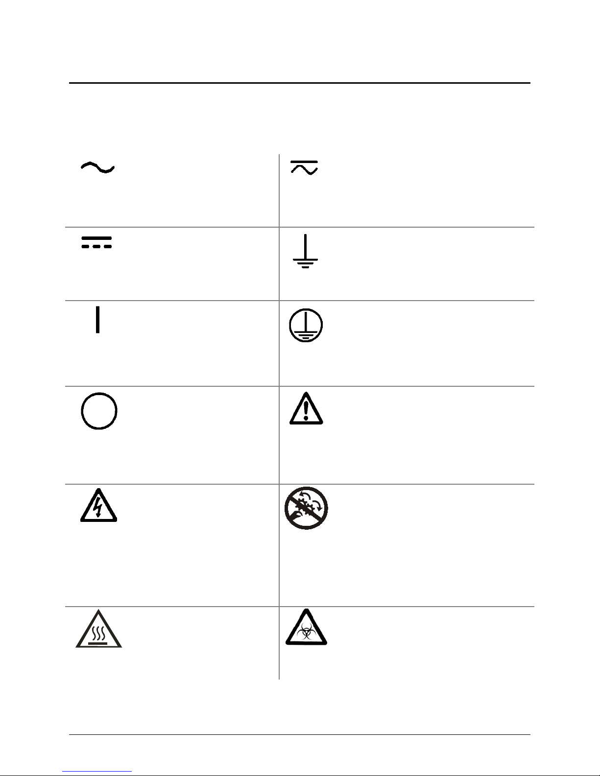
Safety Symbols
Some of these symbols appear on the instrument or accessories:
Alternating current
Courant alternatif
Wechselstrom
Corriente alterna
Corrente alternata
Both direct and alternating current
Courant continu et courant alternatif
Gleich - und Wechselstrom
Corriente continua y corriente alterna
Corrente continua e corrente alternata
Safety Symbols | 15
Direct current
Courant continu
Gleichstrom
Corriente continua
Corrente continua
On (Supply)
Marche (alimentation)
Ein (Verbindung mit dem
Netz)
Conectado
Chiuso
Off (Supply)
Arrêt (alimentation)
Aus (Trennung vom Netz)
Desconectado
Aperto (sconnessione dalla rete
di alimentazione)
Warning, risk of electric shock
Attention, risque de choc
électrique
Gefährliche elektrische schlag
Precaución, riesgo de sacudida
eléctrica
Attenzione, rischio di scossa
elettrica
Earth ground terminal
Borne de terre
Erde (Betriebserde)
Borne de tierra
Terra (di funzionamento)
Protective conductor terminal
Borne de terre de protection
Schutzleiteranschluss
Borne de tierra de protección
Terra di protezione
Caution (refer to accompanying
documents)
Attention (voir documents
d’accompanement)
Achtung siehe Begleitpapiere
Atención (vease los documentos incluidos)
Attenzione, consultare la doc annessa
Warning, risk of crushing or pinching
Attention, risque d’écrasement et
pincement
Warnen, Gefahr des Zerquetschens und
Klemmen
Precaución, riesgo del machacamiento y
sejeción
Attenzione, rischio di schiacciare ed
intrappolarsi
Warning, hot surface
Attention, surface chaude
Warnen, heiße Oberfläche
Precaución, superficie caliente
Attenzione, superficie calda
PowerWave Operator’s Manual
Warning, potential biohazards
Attention, risques biologiques potentiels
Warnung! Moegliche biologische Giftstoffe
Atención, riesgos biológicos
Attenzione, rischio biologico
Page 18

16 | Preface
In vitro diagnostic medical
device
Dispositif médical de
diagnostic in vitro
Medizinisches In-VitroDiagnostikum
Dispositivo médico de
diagnóstico in vitro
Dispositivo medico
diagnostico in vitro
Separate collection for electrical and
electronic equipment
Les équipements électriques et
électroniques font l’objet d’une collecte
sélective
Getrennte Sammlung von Elektro- und
Elektronikgeräten
Recogida selectiva de aparatos eléctricos y
electrónicos
Raccolta separata delle apparecchiature
elettriche ed elettroniche
Consult instructions for use
Consulter la notice d’emploi
Gebrauchsanweisung beachten
Consultar las instrucciones de
uso
Consultare le istruzioni per
uso
BioTek Instruments, Inc.
Page 19

Chapter 1
Introduction
This chapter introduces the PowerWave Microplate
Spectrophotometer, describes its features and specifications, and
provides contact information for technical assistance.
Product Description .................................................................. 18
Package Contents .................................................................... 18
Optional Accessories ................................................................. 19
Specifications .......................................................................... 20
Product Support and Service ..................................................... 23
Page 20

18 | Chapter 1: Introduction
Product Description
The PowerWave offers tunable wavelength selection and wavelength scanning without the
need for interference filters. The eight-channel reader is computer controlled via BioTek’s
Gen5 software. Key features include:
• A variety of read methods including endpoint, kinetic, multiwavelength, and
spectral scanning.
• A monochromator for continuous wavelength selection from 200 to 999 nm (or 340
to 999 nm for the PowerWave 340), in 1-nm increments
• A xenon flash lamp for both UV and visible light absorbance measurements.
• Superior optical specifications, with an extended dynamic range of up to 4.000 OD.
• Ability to read standard 96- and 384-well (PowerWave HT) microplates and
BioTek’s patented BioCell quartz vessel for 1 cm measurements.
• Three reading speeds: normal, rapid, and sweep mode.
• A unique 4-Zone™ temperature control from 4º over ambient to 50ºC that ensures
superior temperature uniformity necessary for kinetic assays.
• Low, medium, high, and variable plate shake speeds with adjustable durations.
• Robot accessible carrier. Compatible with BioTek’s BioStack Microplate Stacker.
If you purchased the BioStack to operate with the PowerWave, refer to
the BioStack Operator’s Manual for installation, setup, and operation
instructions. If you are interested in purchasing the BioS t ack, contact
your local BioTek dealer or visit www.biotek.com.
Package Contents
Package contents and part numbers are subject to change. Please contact
BioTek Customer Care if you have any questions.
• Gen5 Software (PN 5320200)
• Power supply (PN 76053) and power cord (PN varies according to country of use)
• Serial cable (PN 75053)
• PowerWave Operator’s Manual (PN 7281000)
BioTek Instruments, Inc.
Page 21

Optional Accessories
Accessories and part numbers are subject to change. Please contact
BioTek Customer Care if you have any question s, or vi sit www.biotek.com
and use the Accessories search feature.
• USB to Serial Adapter (PN 75104)
• Absorbance Test Plate (PN 7260522)
• BioCell Quartz vessel for 1 cm wavelength fixed pathlength absorbance
measurements (PN 7272051); adapter plate for up to eight BioCells (PN 7270512)
• PowerWave Product Qualification (IQ-OQ-PQ) package (7280520)
• Liquid Test Solutions:
BioTek Wetting Agent (PN 7773002)
BioTek QC Check Solution No. 1 (PN 7120779 for 25 ml; PN 7120782 for 125 ml)
• BioStack Microplate Stacker (contact Customer Care)
Optional Accessories | 19
PowerWave Operator’s Manual
Page 22

20 | Chapter 1: Introduction
Specifications
Microplates
• All models accommodate standard 96-well microplates, and up to 8 BioCells.
• The PowerWave HT also accommodates standard 384-well microplates.
Speed of Reading
The plate read time and accuracy are dependent on the method of reading:
• Normal mode is the slowest of the three available modes. After positioning the
well over the beam, the instrument waits 100 milliseconds before taking the
measurement (8-flash data collection). Note: The 100 ms delay is to allow for
more complete fluid settling.
• Rapid mode is faster than Normal mode because the instrument does not wait
before taking the measurement (8-flash data collection).
• Sweep is the fastest of the three available modes. The plate carrier sweeps each
row past the optics channel without stopping, and collects data with a single
flash at each well as it goes by.
The following read times are based on a single or dual wavelength measurement.
Actual reading speeds may vary, depending upon the reading wavelength selected.
Each wavelength has a unique location within the monochromator, and the different
locations require varying amounts of time to position.
96-Well Read Timing 630 nm 630/450 nm
Normal Read Mode Single Dual
Endpoint 16 to 25 sec. 26 to 44 sec.
Rapid Read Mode Single Dual
Endpoint 16 sec. 26 sec.
Sweep Read Mode Single Dual
Endpoint 11 sec. 16 sec.
Kinetics: All three read modes are available in Kinetics mode. Single wavelength
reads are limited to the following minimum times.
20 seconds from A1 to A1 in Normal mode, single wavelength, depending
upon density of solution.
11 seconds from A1 to A1 in Rapid mode, single wavelength.
5 seconds from A1 to A1 in Sweep mode, single wavelength.
BioTek Instruments, Inc.
Page 23

Specifications | 21
384-Well Read Timing 630 nm 630/450 nm
Normal Read Mode Single Dual
Endpoint 32 to 67 sec. 57 to 129 sec.
Rapid Read Mode Single Dual
Endpoint 28 sec. 49 to 51 sec.
Sweep Read Mode Single Dual
Endpoint 17 sec. 28 sec.
Kinetics: All three read modes are available in Kinetics mode. Single wavelength
reads are limited to the following minimum times.
66 seconds from A1 to A1 in Normal mode, single wavelength, depending
upon density of solution.
23 seconds from A1 to A1 in Rapid mode, single wavelength.
11 seconds from A1 to A1 in Sweep mode, single wavelength.
Optical Specifications
λ range: 200 to 999 nm (PowerWave HT)
340 to 999 nm (PowerWave 340)
λ accuracy: ± 2 nm
λ repeatability: ± 0.2 nm
λ bandpass: 5 nm
Optical Performance
Flat- and round-bottom full-well plates
Absorbance Measurement Range: 0.000 to 4.000 OD
Accuracy:
0.000 to 2.000 OD ± 1.0% ± 0.010 OD Normal and Rapid modes, all plates
2.000 to 2.500 OD ± 3.0% ± 0.010 OD Normal and Rapid modes, all plates
2.500 to 3.000 OD ± 3.0% ± 0.010 OD Normal 96-well plates only
0.000 to 1.000 OD ± 1.0% ± 0.010 OD Sweep mode, all plates
Linearity:
0.000 to 2.000 OD ± 1.0% Normal and Rapid modes, 96-well plates
0.000 to 2.000 OD ± 2.0% Normal and Rapid modes, 384-well plates
2.000 to 2.500 OD ± 3.0% Normal and Rapid modes, all plates
2.500 to 3.000 OD ± 3.0% Normal mode, 96-well plates only
0.000 to 1.000 OD ± 1.0% Sweep mode, all plates
PowerWave Operator’s Manual
Page 24

22 | Chapter 1: Introduction
Repeatability:
0.000 to 2.000 OD ± 1.0% ± 0.005 OD Normal and Rapid modes, 96-well plates
0.000 to 2.000 OD ± 2.0% ± 0.010 OD Normal and Rapid modes, 384-well plates
2.000 to 2.500 OD ± 3.0% ± 0.005 OD Normal and Rapid modes, all plates
2.500 to 3.000 OD ± 3.0% ± 0.005 OD Normal mode, 96-well plates only
0.000 to 1.000 OD ± 2.0% ± 0.010 OD Sweep mode, all plates
For the above performance, the Gain on Optics test should be below 10.0.
Hardware and Environmental Specifications
Light Source: Xenon flash light source
- 10 W max. average power
- Life: 1 billion flashes
Dimensions: 16.0" deep x 8.5" wide x 8.5" high
(40.6 cm deep x 21.6 cm wide x 21.6 cm high)
Weight: 24 lb. (10.9 kg)
Environment: Operational temperature 18° - 40°C
Humidity: 10% to 80%, non-condensing
Power Source: 24-volt external power supply compatible with
100-240 V~ ± 10% @50-60 Hz
Power Consumption: 100 VA max
Temperature Control: 4°C over ambient to 50°C
Temperature Variation: ± 0.5C across the plate @ 37°C (250 µL per well with the
plate sealed)
BioTek Instruments, Inc.
Page 25

Product Support & Service
Contacting the Technical Assistance Center
If your instrument(s) or software fails to function properly, if you have questions about
how to use or maintain your products, or if you need to send an instrument to BioTek
for service or repair, please contact our Technical Assistance Center (TAC).
The TAC is open from 8:30 AM to 5:30 PM (EST), Monday through Friday, excluding
standard U.S. holidays.
Phone: (800) 242-4685 or Fax: (802) 654-0638 E-Mail: tac@biotek.com
(802) 655-4740
Please be prepared to provide the following information:
• Your name and company information, along with a daytime phone or fax
number, and/or an e-mail address
• The product name, model, and serial number
Product Support & Service | 23
Web: www.biotek.com
• The onboard software part number and version (available via Gen5 by selecting
System > Reader Control > Information)
• Gen5 software version information (
Help > About Gen5)
• For troubleshooting assistance or instruments needing repair, the specific steps
that produce your problem and any error codes displayed in Gen5 (see also
Chapter 6)
Returning Instruments for Service/Repair
If you need to return an instrument to BioTek for service or repair, please contact the
TAC for a Return Materials Authorization (RMA) number and the shipping address.
Repackage the instrument properly (see Chapter 2), write the RMA number on the
shipping box, and ship to BioTek.
PowerWave Operator’s Manual
Page 26

24 | Chapter 1: Introduction
BioTek Instruments, Inc.
Page 27

Chapter 2
Installation
This chapter provides instructions for unpacking and setting up the
PowerWave.
Product Registration ................................................................. 26
1: Unpack and Inspect the Instrument ....................................... 26
2: Remove the Carrier Shipping Bracket ..................................... 26
3: Select an Appropriate Location .............................................. 27
4: Connect the Power Supply .................................................... 28
5: Connect the Host Computer .................................................. 29
6: Install Gen5 ........................................................................ 29
7: Turn on the Reader .............................................................. 29
Operational/Performance Qualification ........................................ 30
Repackaging and Shipping Instructions ....................................... 31
Page 28

26 | Chapter 2: Insta lla tion
Product Registration
Register your product(s) with BioTek to ensure that you receive important information
and updates. Register online through BioTek’s Customer Resource Center (CRC) at
www.biotek.com or by contacting BioTek Customer Care.
1: Unpack and Inspect the Instrument
Important! Save all packing materials. If you are sending
the reader to BioTek for repair or replacement, use the original
packing materials. Using other forms of commercially
available packing materials, or failure to follow the packaging
instructions at the end of this chapter, may void your
warranty. If the original materials have been damaged or lost,
replacements are available from BioTek (PN 7283000).
Carefully unpack the reader and accessories. Retain the packing materials for future use.
Inspect the shipping box(es), reader, and accessories for signs of damage.
If the reader is damaged, notify the carrier and your manufacturer’s representative. Keep
the shipping cartons and packing material for the carrier’s inspection. The manufacturer
will arrange for repair or replacement of your reader.
See Preparing the PowerWave for Shipment at the end of this chapter for repacking and
shipping instructions.
2: Remove the Carrier Shipping Bracket
Important! The PowerWave ships with a microplate carrier
shipping bracket that must be removed before the reader is
used. See Figure 1.
1. On the front of the reader, pull down the door to the carrier compartment.
2. Using a screwdriver, remove the three screws that secure the shipping bracket.
3. Secure the bracket to the back of the reader for storage.
BioTek Instruments, Inc.
Page 29

Shipping bracket
3: Select an Appropriate Location | 27
Figure 1: Remove the carrier shipping bracket and store i t on the back of the reader
3: Select an Appropriate Location
Install the reader on a level surface in an area where ambient temperatures remain
between 18°C (64°F) and 40°C (104°F). The reader is sensitive to extreme environmental
conditions; avoid these conditions:
•
Excessive hum idity: Condensation directly on the sensitive electronic circuitry
can cause the reader to fail internal self-checks.
•
Excessive amb ie n t lig h t: Strong light can reduce the linear performance range
of the reader.
•
Dust: Optical density readings may be affected by extraneous particles in the
microplate wells. A clean work area is necessary to ensure accurate readings.
PowerWave Operator’s Manual
Page 30

28 | Chapter 2: Insta lla tion
4: Connect the Power Su pply
Warning! Power Rating. The power supply must be
connected to a power receptacle that provides voltage and
current within the specified rating for the system. Use of an
incompatible power receptacle may produce electrical shock
and fire hazards.
Warning! Electrical Grounding. Never use a plug adapter
to connect primary power to the power supply. Use of an
adapter disconnects the utility ground, creating a severe shock
hazard. Always connect the power supply cord directly to an
appropriate receptacle with a functional ground.
1. Connect the power cord to the power supply.
2. Locate the power inlet on the back of the reader. Insert the power supply’s
plug into the reader’s inlet. Tighten the plug barrel.
3. Plug the cord into an appropriate power receptacle.
Serial por t
Power inlet
Figure 2: Serial port and power supply inlet
BioTek Instruments, Inc.
Page 31

5: Connect the Host Computer | 29
5: Connect the Host Computer
1. Turn the computer off. If the reader is on, turn it off.
2. Connect one end of the supplied serial cable to an appropriate port on the computer.
BioTek offers a USB to Serial Adapter (PN 75104) to connect the serial
cable to a USB port on your computer. Contact BioTek Customer Care.
3. Connect the other end of the cable to the serial port on the back of the reader.
6: Install Gen5
The PowerWave is controlled by Gen5 software running on a
host computer. There is a certain sequence of events that must
be followed to ensure that the software is properly installed
and configured. Please follow the instructions provided in
Gen5 Getting Sta rted Guide to install the software.
7: Turn on the Reader
1. Locate the power on/off switch on the front of the instrument, below the carrier eject
button. See Figure 3 on the next page. Turn on the power. The reader will perform an
internal self-test and carrier homing sequence.
2. Verify that the following occur while the reader performs the self-test:
• The carrier should eject outside the PowerWave, then retract to its home
position inside the reader before it ejects again.
• The LED light on the switch should remain illuminated while the power is
on.
3. Press the carrier eject button. The carrier should retract and the door should close. Press
it again; the carrier should eject.
4. If the test completes successfully, the reader is ready for use.
5. If the test fails, the reader will “beep” continuously. Press the carrier eject button to stop
the beeping. Run a System Test using Gen5 to retrieve an error code (see Chapter 6). If
the test continues to fail, contact BioTek.
PowerWave Operator’s Manual
Page 32

30 | Chapter 2: Insta lla tion
Microplate A1
position
On/off switch
Carrier eject button
Figure 3: Power on/off switch and c a r r ie r ej ect button
Operational/ Pe rformance Qualifica t i on
Your PowerWave Microplate Spectrophotometer was fully tested at BioTek prior to
shipment and should operate properly following the successful completion of the
installation and setup procedures described throughout this chapter.
If you suspect that problems occurred during shipment, if you received the reader back
from BioTek following service or repair, and/or if regulatory requirements dictate that
Operational/Performance Qualification is necessary, turn to
Qualification
now to learn about BioTek’s recommended OQ/PQ procedures for the
PowerWave.
An Installation/Operational/Performance Qualification (IQ/OQ/PQ)
package for the PowerWave is available for purchase (PN 7280520).
Contact your local BioTek dealer for more information.
Chapter 4, Instrument
BioTek Instruments, Inc.
Page 33

Repackaging and Shipping Instructions | 31
Repackaging and Shipping Instructions
Important! Please read all of the information provided below
before preparing the PowerWave for ship ment.
If the reader has been exposed to potentially hazardous material,
decontaminate it to minimize the risk to all who come in contact with
the reader during shipping, handling, and servicing. Decontamination
prior to shipping is required by the U.S. Department of
Transportation regulations. See Chapter 5 for decontamination
instructions.
Remove the microplate from the carrier before shipment. Spilled
fluids can contaminate the optics and damage the instrument.
The instrument’s packaging design is subject to change. If the
instructions in this section do not apply to the packaging materials
you are using, please contact BioTek’s Technical Assistance Center for
guidance.
Replace the shipping hardware before repackaging the reader. Please
contact BioTek if you have misplaced the microplate carrier shipping
bracket (PN 7282014) or mounting screws (3, PN 19186).
If you need to ship the reader to BioTek for service or repair, be sure
to use the original packaging materials. Other forms of commercially
available packaging are not recommended and can void the
warranty.
The shipping materials are designed to be used no more than five
times. If the original materials have been damaged, lost, or used more
than five times, contact BioTek to order replacements.
1. Contact BioTek’s Technical Assistance Center for an
Authorization) number and the shipping address before returning equipment for
service.
2. Decontaminate the reader according to the instructions provided in
3. Install the carrier shipping bracket (refer to
Bracket
• If the carrier is extended, press the carrier eject button to retract it.
on page 26):
Remove the Carrier Shipping
RMA (Return Materials
Chapter 4.
• Turn off the reader.
PowerWave Operator’s Manual
• Disconnect the power supply and serial cable from the back of the reader.
Page 34

32 | Chapter 2: Insta lla tion
• Refer to Figure 1 on page 27. Using a screwdriver, remove the carrier
shipping bracket and screws from the back of the reader.
• Pull down the door to the carrier compartment.
• Install the carrier shipping bracket to the front of the carrier and mounting
block.
Refer to
Figure 4 on page 33 when performing these steps:
1. Place two foam caps into the bottom of the shipping container.
2. Slide the accessories box into the shipping container.
3. Place the reader inside its plastic bag and carefully lower it into the two
foam caps in the bottom of the box. Note the orientation of the reader in the
box.
4. Place two foam caps over the reader.
5. Place the power supply, cord, and communication cables into the
accessories box.
6. Close the top of the box and secure it with shipping tape. When finished,
write the RMA number on the outside of the box and ship the box to
BioTek.
BioTek Instruments, Inc.
Page 35

Repackaging and Shipping Instructions | 33
Plastic bag
Bottom foam caps
(2)
Top foam caps (2)
Power cord
PowerWave Operator’s Manual
Figure 4: Packing the PowerWave
Page 36

34 | Chapter 2: Insta lla tion
BioTek Instruments, Inc.
Page 37

Chapter 3
Operation
This chapter briefly describes how to use BioTek’s Gen5 software to
operate the PowerWave. It also contains recommendations for
achieving optimum performance.
Operating the PowerWave ......................................................... 36
Getting Started with Gen5......................................................... 38
Recommendations for Optimum Performance .............................. 37
Where to Go Next .................................................................... 38
Page 38

36 | Chapter 3: Operation
Operating the PowerWave
Most users will operate the PowerWave using BioTek’s Gen5 software. If you have not
already done so, please follow the instructions in Chapter 2 and the Gen5 Getting Started
Guide for connecting the host computer and installing Gen5.
• For custom applications, BioTek provides a serial communication protocol (PN
7266201-SP). Contact your BioTek dealer.
Getting Started with Gen5
These instructions briefly describe how to create and run an Experiment in Gen5. For more
information, or if the instructions below do not match what you see in Gen5, refer to the
Gen5 Getting Started Guide and help system.
For Gen5 version 2.x:
1. Start Gen5.
2. If the Task Manager appears, select Read Now > New and skip to step 4.
Otherwise, select
3. Select Read Now > New. Gen5 will open the procedure dialog. Skip to step 4.
For Gen5 version 1.x:
1. Start Gen5. If the Welcome screen appears, select Read a Plate and skip to
step 4. Otherwise, select
2. Select Default Protocol and click OK. Gen5 will open the Experiment
workspace, which includes the Protocol menu tree and Plate screen.
3. Select Plate > Read or click the Read Plate icon. The Procedure dialog will
open. Go to step 4.
For any version:
4. Select a Plate Type.
5. Click Read to open the Read Step dialog.
Select a Read Type.
6.
7. Select or enter the wavelength(s) at which the plate will be read.
File > New Task from the main view.
File > New Experiment from the main view.
8. Define other reading parameters as desired. Click the Help button for
assistance.
9. When complete, click OK to return to the Procedure dialog.
10. Click OK to save and close the Procedure dialog.
BioTek Instruments, Inc.
Page 39

Recommendations for Optimum Performance | 37
• Gen5 version 1.x only: The Plate Reading dialog will open. Enter any
desired information, place the plate on the carrier, and then click
begin the plate read. If the Save As dialog opens, enter a File name, choose a
file location (Save in:) and click Save.
11. Click OK when the Load Plate dialog appears. The plate will be read.
• To view the raw data results, use the Data drop-down arrow in the Plate
screen to select one wavelength. The results will be displayed for the
selected wavelength. Repeat, for other wavelengths.
• To analyze, manipulate, or print results, Protocol parameters should be
defined. Refer to the Gen5 Help system for instructions.
Recommendations for Optimum Performance
• Microplates should be perfectly clean and free of dust or bottom scratches. Use
new microplates from sealed packages. Do not allow dust to settle on the surface of
the solution; use microplate covers when not reading the plate. Filter solutions to
remove particulates that could cause erroneous readings.
READ to
• Although the PowerWave supports most flat, U-bottom, and V bottom microplates,
the reader achieves optimum performance with optically clear, flat-bottomed wells.
• Non uniformity in the optical density of the well bottoms can cause loss of
accuracy, especially with U- and V-bottom polyvinyl microplates. Check for this by
reading an empty microplate. Dual wavelength readings can eliminate this
problem, or bring the variation in density readings to within acceptable limits for
most measurements.
• Inaccuracy in pipetting has a large effect on measurements, especially if smaller
volumes of liquid are used. For best results, use at least 100 µL per well in a 96-well
plate and 25 µL in a 384-well plate (if supported).
• Dispensing solution into 384-well plates often traps air bubbles in the wells, which
may result in inaccurate readings. A dual-wavelength reading method usually
eliminates these inaccuracies; however, for best results, remove the air bubbles by
degassing the plate in a vacuum chamber before reading.
• The inclination of the meniscus can cause loss of accuracy in some solutions,
especially with small volumes. Agitate the microplate before reading to help bring
this problem within acceptable limits. Use Tween
®
20, if possible (or some other
wetting agent) to normalize the meniscus. Some solutions develop menisci over a
period of several minutes. This effect varies with the brand of microplate and the
solution composition. As the center of the meniscus drops and shortens the light
path, the density readings change. The meniscus shape will stabilize over time.
PowerWave Operator’s Manual
Page 40

38 | Chapter 3: Operation
Where to Go Next
• Refer to the Gen5 Getting Started Guide and help system to learn more about using
Gen5 to operate the PowerWave.
• Review the remaining chapters in this Operator’s Manual to learn how to test the
performance of the PowerWave, clean and maintain the reader, and troubleshoot
problems.
BioTek Instruments, Inc.
Page 41

Chapter 4
Instrument Qualification
This chapter discusses procedures for qualifying the reader’s initial
and ongoing performance.
Recommended Qualification Schedule ......................................... 40
Qualification Procedures ............................................................ 41
System Test ............................................................................ 41
Absorbance Plate Test .............................................................. 44
Liquid Testing .......................................................................... 47
Page 42

40 | Chapter 4: Instrumen t Q ualification
Overview
This chapter contains BioTek Instruments’ recommended Installation Qualification (IQ),
Operational Qualification (OQ), and Performance Qualification (PQ) procedures for the
PowerWave Microplate Spectrophotometer.
Every PowerWave reader is fully tested at BioTek prior to shipment and should operate
properly upon initial setup. If you suspect that a problem occurred during shipment, if
you have received the equipment after returning it to the factory for service, and/or if
regulatory requirements dictate that you qualify the equipment on a routine basis, you
should perform the procedures outlined in this chapter.
Recommended Qualification Schedule
This schedule defines the factory-recommended intervals for qualifying a PowerWave
used two to five days a week. The actual frequency, however, may be adjusted depending
on your usage of the instrument. This schedule assumes the reader is properly maintained
as outlined in
Chapter 5.
The risk factors associated with your tests may require that the
Operational and Performance Qualification procedures be performed
more or less frequ en t ly than indicated here.
Initially
Installation
Qualification
System Test
Absorbance Plate Test
Liquid Test 1*
Liquid Test 2*
Liquid Test 3**
Operational
Qualification
Initially/
Annually
Performance
Qualification
Monthly Quarterly
* Run Liquid Test 1 if you have an Absorbance Test Plate. If you do not have a Test
Plate, run Liquid Test 2.
** Liquid Test 3 is optional; it is provided for sites requiring verification at wavelengths
lower than those attainable with the Absorbance Test Plate.
BioTek Instruments, Inc.
Page 43

Qualification P r oc e dures | 41
Qualification Pr ocedures
Your reader was fully tested at BioTek prior to shipment and should operate properly
upon initial setup. If you suspect that problems occurred during shipment or if regulatory
requirements dictate that Operational and/or Performance Qualification is necessary, you
should perform the following tests.
•
System Test: Verifies proper gains, bulb operation, low electronic noise, and
incubator functionality. The test report includes the reader’s serial number and
basecode software part number and version number.
•
Absorbance Plate Test: Uses BioTek’s Absorbance Test Plate to confirm the
mechanical alignment, optical accuracy/linearity, repeatability, channel-to-channel
variation, and wavelength accuracy of the instrument.
•
Liquid Tests: Uses liquid solutions in a microplate to confirm mechanical
alignment, optical accuracy/linearity, repeatability, and channel-to-channel
variation of the instrument.
System Test
The PowerWave automatically runs the System Test each time it is powered on. The test
can also be run (and a report generated) using Gen5. The System Test report should be
printed to document periodic testing and for troubleshooting purposes. See a sample
System Test report on page 42.
If the power-up System Test fails, the reader will beep. If this happens, press the carrier
eject button to stop the beep and then attempt to run the System Test using Gen5 to
retrieve an error code from the instrument.
See Chapter 6 for a list of possible error codes and their probable causes.
1. Adjust the wavelength table, if desired:
• From Gen5’s main screen, select
• Highlight the PowerWave and click
• Click the
• Enter the desired wavelength values and click
download them to the reader.
2. Run the test:
Absorbance tab.
System > Reader Configuration.
View/Modify > Setup.
Send Wavelengths to
• Select
System > Diagnostics > Run System Test.
• The test will run and results will appear in a pass/fail format.
PowerWave Operator’s Manual
Page 44

42 | Chapter 4: Instrument Qualification
Sample System Test Report
Test Date/Time: 11/06/2009 10:33:27 AM
Reader: 123456
Operator: System Administrator
Comments: System Test performed during IQ
Operator ID:______________________________________________________________
Notes:____________________________________________________________________
__________________________________________________________________________
SYSTEM SELF TEST
7280201 Version 1.20 128790
Lambda: 200 Gain: 3.28 Resets: 1
Channel: Ref 1 2 3 4 5 6 7 8
Air: 20506 35689 37068 35775 39588 36708 32962 35604 34634
Dark: 9911 10002 10031 9880 9980 9904 9930 9869 9974
Delta: 10595 25687 27037 25895 29608 26804 23032 25735 24660
Lambda: 405 Gain: 2.53 Resets: 2
Channel: Ref 1 2 3 4 5 6 7 8
Air: 20072 35592 39355 36205 38232 37636 33564 36682 36095
Dark: 9914 9960 9975 9900 9945 9915 9928 9895 9948
Delta: 10158 25632 29380 26305 28287 27721 23636 26787 26147
Lambda: 490 Gain: 1.72 Resets: 2
Channel: Ref 1 2 3 4 5 6 7 8
Air: 20280 35642 39779 36310 38486 37962 33494 36949 36219
Dark: 9919 9949 9960 9909 9939 9919 9928 9905 9942
Delta: 10361 25693 29819 26401 28547 28043 23566 27044 26277
Lambda: 550 Gain: 2.51 Resets: 1
Channel: Ref 1 2 3 4 5 6 7 8
Air: 20248 35530 39702 36099 38344 37862 33339 36781 36154
Dark: 9914 9985 10007 9891 9967 9910 9930 9881 9963
Delta: 10334 25545 29695 26208 28377 27952 23409 26900 26191
Lambda: 630 Gain: 3.94 Resets: 1
Channel: Ref 1 2 3 4 5 6 7 8
Air: 20230 35302 39381 35837 38113 37659 33193 36503 35852
Dark: 9907 10018 10053 9870 9990 9900 9931 9854 9984
Delta: 10323 25284 29328 25967 28123 27759 23262 26649 25868
Lambda: 999 Gain: 5.33 Resets: 1
Channel: Ref 1 2 3 4 5 6 7 8
Air: 19977 34186 39376 35131 37500 36779 32458 36029 35249
Dark: 9900 10050 10095 9849 10010 9888 9934 9831 10004
Delta: 10077 24136 29281 25282 27490 26891 22524 26198 25245
BioTek Instruments, Inc.
Page 45

System Test | 43
Channel: Ref 1 2 3 4 5 6 7 8
Noise Max: 9878 9980 10018 9847 9923 9893 9919 9836 9964
Noise Min: 9877 9978 10017 9846 9922 9891 9917 9835 9962
Delta: 1 2 1 1 1 2 2 1 2
INCUBATOR SELF TEST
Temperature Setpoint: 37.0 Current Average: 37.1 A/D Test: PASS
Zone 1: 37.1 Min: 37.0 Max: 37.1 Range: PASS Thermistor: PASS
Zone 2: 37.0 Min: 37.0 Max: 37.1 Range: PASS Thermistor: PASS
Zone 3: 37.1 Min: 37.1 Max: 37.1 Range: PASS Thermistor: PASS
Zone 4: 37.1 Min: 37.0 Max: 37.1 Range: PASS Thermistor: PASS
AUTOCAL ANALYSIS
Upper Left Corner: x= 1676 y= 9220
Lower Left Corner: x= 2448 y= 8944
The INCUBATOR SELF TEST shows
the PASS or FAIL condition of the
four heating zones in the incubator.
Lower Right Corner: x= 11140 y= 8912
Upper Right Corner: x= 10364 y= 9172
Delta 1: 1676 - 2448= -772
Delta 2: 10364 -11140= -776
Delta 3: 9172 - 9220= -48
Delta 4: 8912 - 8944= -32
Middle Sensor: x= 13852
AUTOCAL ANALYSIS provides coordinates of the
last autocalibration procedure perfo r med on the
instrument. AUTOCAL is not included in the
SYSTEM TEST result given below.
Tested: 13852
Delta: +0
SYSTEM TEST PASS
The SYSTEM TEST result will be either PASS or FAIL and
refers only to the optics portion of the test.
PowerWave Operator’s Manual
Page 46

44 | Chapter 4: Instrumen t Q ualification
Absorbance Plate Test
This test uses BioTek’s Absorbance Test Plate to confirm the mechanical alignment, optical
density accuracy/linearity, repeatability, channel-to-channel variation and wavelength
accuracy of the PowerWave. The test compares the reader’s optical density and
wavelength measurements to NIST-traceable values.
If you do not have an absorbance test plate, you c an run Liquid Test 2
to test accuracy/linearity, repea tability, and alignment. See page 50.
Test Plate and Certificates
To run the Absorbance Plate Test, you will need BioTek's Absorbance Test Plate (PN
7260522), with its accompanying certificates.
• The
Standards Cert ificate contains standard OD values for the filters at
several different wavelengths.
• The
Peak Wavelength Certificate contains one or more peak wavelength
values for the glass filter in position C6 on the plate. Each value has a valid test
range associated with it. For example, a Peak Wavelength value may be 586 nm
with a test range of 580 to 590 nm (or tolerance values of –6/ +4).
The instructions provided below and on the following page are
guidelines. Refer to the Gen5 Help system for more information.
Enter the Absorbance Test Plate Data
Before performing the Absorbance Plate Test for the first time (and after the plate is
recalibrated by BioTek), enter data from the Standards and Peak Wavelengths
Certificates into Gen5:
• Select
System > Diagnostics > Test Plates > Add/Modify Plates and
click
Add. Click Help for guidance when setting the wavelengths and entering
the OD and peak wavelength value(s).
Run the Absorbance Plate Test
Place the Absorbance Test Plate in the carrier so that well A1 is in the right rear corner
of the carrier.
• Select
System > Diagnostics > Test Plates > Run.
• If the Instrument Selection dialog appears, select the appropriate reader.
• If the Select Test Plate dialog appears, select the appropriate test plate.
• Enable ‘Perform peak wavelength test’ and enter any required information
• Click
Start Test.
BioTek Instruments, Inc.
Page 47

Absorbance Plate Test | 45
Sample Absorbance Plate Test Report
Universal Test Plate Analysis
Wavelength: 405
Alignment Results
A1= 0.000 PASS A12= 0.000 PASS H1= 0.000 PASS H12= 0.000 PASS
Accuracy Results
C01 D04 E02 F05 G03 H06
STANDARD 0.147 2.945 0.618 2.279 1.133 1.701
DATA 0.139 2.914 0.613 2.265 1.128 1.694
RESULT PASS PASS PASS PASS PASS PASS
F12 E09 D11 C08 B10 A07
STANDARD 0.147 2.945 0.618 2.279 1.133 1.701
DATA 0.145 2.910 0.613 2.264 1.125 1.692
RESULT PASS PASS PASS PASS PASS PASS
Repeatability Results
C01 D04 E02 F05 G03 H06
READ1 0.139 2.914 0.613 2.265 1.128 1.694
READ2 0.141 2.913 0.616 2.265 1.128 1.694
RESULT PASS PASS PASS PASS PASS PASS
F12 E09 D11 C08 B10 A07
READ1 0.145 2.910 0.613 2.264 1.125 1.692
READ2 0.140 2.914 0.614 2.265 1.126 1.692
RESULT PASS PASS PASS PASS PASS PASS
Turnaround Results
C01 D04 E02 F05 G03 H06
READ1 0.139 2.914 0.613 2.265 1.128 1.694
F12 E09 D11 C08 B10 A07
READ2 0.145 2.910 0.613 2.264 1.125 1.692
RESULT PASS PASS PASS PASS PASS PASS
Spectral Scan Results
580nm= 1.933 586nm= 2.892
581nm= 1.956 587nm= 2.753
582nm= 2.059 588nm= 2.516
583nm= 2.253 589nm= 2.334
584nm= 2.511 590nm= 2.186
585nm= 2.785
Test Plate Standard=587nm
Calculated Peak=586nm PASS
PowerWave Operator’s Manual
Page 48

46 | Chapter 4: Instrumen t Q ualification
Test Results
For the Accuracy, Linearity, Repeatability, and Channel-to-Channel
Variation te sts, there may not be a pass/fail indication for filter values
that are beyond the specified accuracy range of the instrument.
The Absorbance Test Plate Analysis contains results for the following:
• Mechanical Alignment: This portion of the test measures the alignment of the
microplate carrier with the optical path. A reading greater than 0.015 OD
represents an out-of-alignment condition.
• Accuracy/Linearity: Accuracy is a measure of the absorbance (optical density)
of Test Plate wells C01, D04, E02, F05, G03, and H06 as compared with known
standard values contained in the plate’s Standards Certificate. Linearity of the
optical density readings is confirmed by default if the readings are accurate. To
further verify this, perform a regression analysis on the Test Plate OD values in
a program such as Microsoft
expected.
®
Excel. An R Square value of at least 0.99 is
• Repeatability: Repeatability is a measure of the instrument’s ability to read the
same well with minimum variation between the two reads with the well in the
same location.
• Channel-to-Channel Variation: This test ensures that selected channels read
the same value for a filter as their paired channel when the plate is rotated 180°
in the plate carrier. The channel/well “pairs” for the turnaround test are:
C01/F12; D04/E09; E02/D11; F05/C08; G03/B10; H06/A07.
• Wavelength Accuracy: If ‘Perform peak wavelength test’ is enabled as part of
the Absorbance Plate Test, the C6 filter is scanned across a specified
wavelength range in 1-nm increments. The wavelength of the maximum
absorbance is compared with the peak wavelength value(s) entered in the
software. The accuracy of the wavelength should be ± 3 nm (± 2 nm
instrument, ± 1 nm filter allowance).
For example, if the test range is 580 to 590 nm, the Certificate value is 587 nm,
and the reader reports a peak value of 590 nm, then the reader meets
specifications. If the reader reports 591 nm, then the reader does not meet
specifications.
BioTek Instruments, Inc.
Page 49

Liquid Testing | 47
Liquid Testing
Conducting Liquid Tests confirms the reader’s ability to perform to specification with
liquid samples. Liquid testing differs from testing with the Absorbance Test Plate in that
liquid in the wells has a meniscus, whereas the Test Plate’s neutral density glass filters do
not. The optics characteristics may differ in these two cases, thus alerting the operator to
different types of problems.
• If you have the Absorbance Test Plate, you only need to perform Liquid Test 1 for
routine testing.
• If you do not have the Absorbance Test Plate, you can test the accuracy/linearity,
repeatability, and alignment of the reader by performing Liquid Test 2.
• If you must test the reader’s performance at 340 nm, perform Liquid Test 3.
• BioTek offers a dye solution (PN 7120779, 25 mL; or 7120782, 125 mL) that may be
used in the stock solution formulation for Liquid Tests 1 and 2, or, if you prefer,
you may use Solution A described on the next page. The purpose of the
formulation is to create a solution that absorbs light at approximately 2.000 OD full
strength when dispensed at 200 µL in a flat-bottom microplate well.
• Alternatively, any solution that gives a stable color will suffice. (This includes
substrates incubated with an enzyme preparation and then stopped with an acidic
or basic solution.) Some enzyme/substrate combinations that may be used as
alternates to the described dye are shown below.
Typical Enzyme-Substrate Combinations and Stopping Solutions
Enzyme Substrate Stopping Solution
Alkaline Phosphate o-nitrophenyl phosphate 3N sodium hydroxide
beta-Galactosidase o-nitrophenyl -beta-D
1M sodium carbonate
galactopyranoside
Peroxidase 2,2'-Azino di-ethylbenzothiazoline-
sulfonic acid (ABTS)
citrate-phosphate buffer,
pH 2.8
Peroxidase o-phenylenediamine 0.03N sulfuric acid
PowerWave Operator’s Manual
Page 50

48 | Chapter 4: Instrumen t Q ualification
Absorbance Liquid Test 1
Absorbance Liquid Test 1 confirms repeatability and alignment of the reader when a
solution is used in the microplate. If these tests pass, then the lens placement and optical
system cleanliness are proven.
Materials
Manufacturer part numbers are subject to change.
• New 96-well, clear, flat-bottom microplate (Corning Costar
®
#3590
recommended)
• Stock Solution A or B, which may be formulated by diluting a dye solution
available from BioTek (A) or from the ingredients listed below (B).
Solution A
• BioTek QC Check Solution No. 1 (PN 7120779, 25 mL; PN 7120782, 125 mL)
• Deionized water
• 5-mL Class A volumetric pipette
• 100-mL volumetric flask
1. Pipette a 5-mL aliquot of BioTek QC Check Solution No. 1 into a 100-mL
volumetric flask.
2. Add 95 mL of DI water; cap and shake well. The solution should measure
approximately 2.000 OD when using 200 µL in a flat-bottom microwell.
Solution B
• Deionized water
• FD&C Yellow No. 5 dye powder (typically 90% pure)
®
• Tween
20 (polyoxyethylene (20) sorbitan monolaurate) or BioTek wetting
agent (PN 7773002) (a 10% Tween
• Precision balance with capacity of 100g minimum and readability of 0.001g
• Weigh boat
• 1-liter volumetric flask
1. Weigh out 0.092 g of FD&C Yellow No. 5 dye powder into a weigh boat.
2. Rinse the contents into a 1-liter volumetric flask.
3. Add 0.5 mL of Tween 20, or 5 mL of BioTek’s wetting agent.
4. Fill to 1 liter with DI water; cap and shake well. The solution should measure
approximately 2.000 OD when using 200 µL in a flat-bottom microwell.
®
solution)
BioTek Instruments, Inc.
Page 51

Prepare the Plate
A 96-well, flat-bottom microplate is required for this test (Corning
Costar® #3590 is recommended). Use a new microplate; any
fingerprints or scratches may cause variations in readings.
1. Using a freshly prepared stock solution (Solution A or B), prepare a 1:2
dilution using deionized water (one part stock, one part deionized water;
the resulting solution is a 1:2 dilution).
2. Pipette 200 µL of the concentrated solution into the first column of wells in
the new 96-well microplate.
3. Pipette 200 µL of the diluted solution into the second column of wells.
Important! After pipetting the diluted test solution into
the microplate and before reading the plate, we strongly
recommend shaking the plate at Variable speed for four
minutes. This will allow any air bubbles in the solution
to settle and the meniscus to stabilize. Alternatively,
wait 20 minutes after pipetting the diluted test solution
before reading the plate.
Liquid Testing | 49
Read the Plate
1. Read the microplate five times at 405 nm using normal reading mode,
single wavelength, no blanking (“Normal” plate position).
2. Rotate the microplate 180° so that well A1 is now in the H12 position. Read
the plate five more times (“Turnaround” plate position).
3. Print out the ten sets of raw data, or export them to an Excel spreadsheet.
Calculations
1. Calculate the mean value for each physical well location in columns 1 and 2
for the five plates read in the Normal position, and then again for the five
plates read in the Turnaround position. This will result in 32 mean values.
2. Perform a mathematical comparison of the mean values for each microwell
in its Normal and Turnaround positions (A1/H12, A2/H11, B1/G12,
B2/G11, and so on). In order to pass this test, the differences in the
compared mean values must be within the accuracy specification for the
instrument.
For Example:
If the mean value for well A1 in the Normal position is 1.902, where the
PowerWave Operator’s Manual
specified accuracy is ± 1.0% ± 0.010 OD, then the expected range for the
Page 52

50 | Chapter 4: Instrumen t Q ualification
mean of the same well in its Turnaround (H12) position is 1.873 to 1.931
OD.
1.902 * 0.01 + 0.010 = 0.029; 1.902 – 0.029 =
1.873; 1.902 + 0.029 = 1.931
If any set of mean values is out of the expected range, review the other three
sets of mean values for the same channel pair. For example, if the A1/H12
comparison fails (the wells are not within the expected range of each other),
review the comparisons of A2/H11, H1/A12, and H2/A11. If two or more
sets of mean values for a channel pair are out of the expected range, there is
a problem with one of the eight read channels. If only one of the four mean
values results in a failure, check the well for debris and the plate for
scratches or fingerprints.
Accuracy Specification:
For comparison in this test, the following accuracy specifications are
applied, using Normal/Standard read mode and a 96-well microplate.
± 1.0% ± 0.010 OD from 0.000 to 2.000 OD
± 3.0% ± 0.010 OD from 2.000 OD to 3.000 OD
Absorbance Liquid Test 2
The recommended method of testing the instrument performance is to use the
Absorbance Test Plate to confirm alignment, accuracy/linearity, and repeatability. If a
Test Plate is not available, Liquid Test 2 can be used for these tests.
Materials
• A new 96-well, flat bottom microplate (Corning Costar
recommended)
• Ten test tubes, numbered consecutively, stored in a rack
• Calibrated hand pipette (Class A volumetric pipette recommended)
• Solution A or B (these are the same solutions as for Liquid Test 1)
• A 0.05% solution of deionized water and Tween
Prepare the Dilutions
Create a percentage of dilution series, beginning with 100% of the original
concentrated stock solution (A or B) in the first tube, 90% of the original
solution in the second tube, 80% in the third tube, all the way to 10% in the
tenth tube. Dilute using the 0.05% solution of deionized water and Tween
This solution can also be made by diluting the BioTek wetting agent 200:1.
®
20
®
#3590 is
®
20.
BioTek Instruments, Inc.
Page 53

Liquid Testing | 51
Test Tube Dilutions
Tube Number 1 2 3 4 5 6 7 8 9 10
Volume of Original
20 18 16 14 12 10 8 6 4 2
Solution (mL)
Volume of 0.05%
0 2 4 6 8 10 12 14 16 18
Tween solution (mL)
Absorbance expected
2.0 1.8 1.6 1.4 1.2 1.0 0.8 0.6 0.4 0.2
if original solution is
2.000 OD at 200 µL
The choice of dilution s and the absorbance of the original solution can
be varied. Use this table as a model for calculating the expected
absorbances of a series of dilutions, given a different absorba n c e of
the original solutio n.
Prepare the Plate
1. Pipette 200 µL of the concentrated solution from tube 1 into each well of the
first column, A1 to H1, of a new flat-bottom microplate.
2. Pipette 200 µL from each of the remaining tubes into the wells of the
corresponding column of the microplate (tube 2 into wells A2 to H2, etc.).
After pipetting the diluted test solution into the microplate and
before reading the plate, we strongly recommend shaking the
plate at Variable speed for four minutes. This will allow any air
bubbles in the solution to settle and the meniscus to stabilize.
Alternatively, wait 20 minutes after pipet ting the diluted test
solution before reading the plate.
Linearity and Repeatability Tests
1. Read the microplate prepared above using a normal mode dual wavelength
at 450 nm with 630 nm as the blank. Repeat the read four times for a total of
five reads. Retain the plate for the Alignment test.
2. Print out the five sets of Delta OD data, or export them to an Excel
spreadsheet.
3. Calculate the results for Linearity:
• Calculate the mean absorbance for each well, and average the means for
each concentration.
• Perform a regression analysis on the data to determine if there is
adequate linearity.
PowerWave Operator’s Manual
Page 54

52 | Chapter 4: Instrumen t Q ualification
Since it is somewhat difficult to achieve high pipetting accuracy when
conducting linear dilutions, an R Square value of at least 0.99 is
considered adequate.
4. Calculate the results for Repeatability:
• Calculate the mean and standard deviation for the five readings taken in
Step 1 at each concentration. Only one row of data needs to be analyzed.
• For each mean below 2.000 OD, calculate the allowed deviation using
the repeatability specification for a 96-well plate of ± 1.0% ± 0.005 OD. If
above 2.000 OD, apply the ± 3.0% ± 0.005 specification.
• The standard deviation for each set of readings should be less than the
allowed deviation.
Example: Absorbance readings of 1.950, 1.948, 1.955, 1.952, and 1.950
will result in a mean of 1.951, and a standard deviation of 0.0026. The
mean (1.951) multiplied by 1% (1.951 * 0.010) = 0.0195, which, when
added to the 0.005 (0.0195 + 0.005) = 0.0245 OD, which is the allowable
deviation. Since the standard deviation is less than this value, the reader
meets the test criteria.
Repeatability Spec ification:
± 1% ± 0.005 OD from 0.000 OD to 2.000 OD
± 3% ± 0.005 OD from 2.000 OD to 3.000 OD
Channel-to-Channel Variation and Alignment
1. Using the plate prepared for the tests above, conduct a turnaround test by
reading the plate with the A1 well in the H12 position five times. This test
results in four comparisons of each channel to its corresponding channel,
two in column 1, and two in column 2.
2. Calculate the means of the wells in columns 1 and 2 in the normal plate
position (data is from the tests above) and in the turnaround position (from
Step 1 above). Compare the mean reading for well A1 to its mean reading
when in the H12 position.
3. Compare the mean values for the other wells to their corresponding mean
values with the well in the turnaround position. (Compare B1 to G12, C1 to
F12, D1 to E12, E1 to D12, F1 to C12, G1 to B12, H1 to A12, A2 to H11, and
B2 to G11, etc.). The difference in the values for any two corresponding
wells should be within the accuracy specification for the instrument.
For example: If the mean of well A1 in the normal position is 1.902, where
the specified accuracy is ± 1.0% ± 0.010 OD, then the expected range for the
mean of the same well in the H12 position is 1.873 to 1.931 OD. (1.902 * 1% =
0.019 + 0.010 = 0.029, which is added and subtracted from 1.902 for the
range.)
BioTek Instruments, Inc.
Page 55

If any set of well values is out of the expected range, review the other three
sets for the same channel pair. Thus, if A1 and H12 are not within range of
each other, review the compliance of H1 to A12, A2 to H11, and H2 to A11.
This will confirm that there is a problem in one of the eight read channels,
or indicate that the result of one set of wells was in error. If any two sets of
well values for a channel pair are out of the allowed accuracy range, there
may be contamination on, or a problem with, one of the lenses.
4. If the four corner wells are within the accuracy range, the reader is also in
alignment.
Absorbance Liquid Test 3 (Optional)
Materials
Liquid Testing | 53
• A new 96-well, flat-bottom microplate (Corning Costar
recommended)
• Calibrated hand pipette(s)
• Beakers and graduated cylinder
• Precision balance with a readability of 0.01 g
• Buffer solution as described below
Buffer Solution
• Deionized water
• Phosphate-buffered saline (PBS), pH 7.2-7.6, Sigma
equivalent)
• β-NADH Powder (β-Nicotinamide Adenine Dinucleotide, Reduced Form)
Sigma bulk catalog number N 8129, or preweighed 10-mg vials, Sigma
number N6785-10VL (or BioTek PN 98233). Store the powder according to
the guidelines on its packaging.
1. Prepare a PBS solution using Sigma
2. In a beaker, mix 50 mL of the PBS solution with 10 mg of the β-NADH
powder and mix thoroughly. This is the
®
tablets #P4417 (or
®
tablets.
100% Test Solution.
®
#3590 is
PowerWave Operator’s Manual
Page 56

54 | Chapter 4: Instrument Qualification
Prepare the Plate
1. Prepare the 75% Test Solution by mixing 15 mL of the 100% Test Solution
with 5 mL of the PBS solution.
2. Prepare the 50% Test Solution by mixing 10 mL of the 100% Test Solution
with 10 mL of the PBS solution.
3. Pipette the three solutions into the new 96-well microplate:
¾ 150 µL of the 100% Test Solution into all wells of columns 1 and 2
¾ 150 µL of the 75% Test Solution into all wells of columns 3 and 4
¾ 150 µL of the 50% Test Solution into all wells of columns 5 and 6
Important! After pipetting the diluted test solution
into the microplate and before reading the plate, we
strongly recommend shaking the plate at Variable
speed for four minutes. This will allow any air bubbles
in the solution to settle and the meniscus to stabilize.
Alternatively, wait 20 minutes after pipetting the
diluted test solution before reading the plate.
Read the Plate
1. Read the microplate five times using Normal mode, single wavelength at
340 nm, no blanking (or blank on air).
2. Print the five sets of raw data or export it to an Excel spreadsheet using
Gen5.
BioTek Instruments, Inc.
Page 57

Liquid Testing | 55
Analyze the Results
1. For each well, calculate the mean and standard deviation of the five readings.
2. For each mean calculated in step 1, calculate the allowed deviation using the
repeatability specification for a 96-well plate of ± 1.0% ± 0.005 OD (mean * 0.01
+ 0.005).
3. For each well, compare the standard deviation calculated in step 1 with the
allowed deviation calculated in step 2. The standard deviation should be less
than the allowed deviation.
Example: Five readings in well A1 of 0.802, 0.802, 0.799, 0.798, and 0.801 will
result in a mean of 0.8004, and a standard deviation of 0.0018. The mean
multiplied by 1.0% (0.8004 * 0.010) = 0.008, which, when added to the 0.005 (0.008
+ 0.005) = 0.013, which is the allowable deviation for well A1. Since the standard
deviation for well A1 is less than 0.013, the reader meets the test criteria.
4. Calculate the results for Linearity:
• For each of the three dye concentrations, calculate the mean absorbance
for the wells containing that solution (mean of wells A1 to H2, A3 to H4,
and A5 to H6).
• Perform a regression analysis on the data to determine if there is
adequate linearity.
Expected Results: Since it is somewhat difficult to achieve high
pipetting accuracy when conducting linear dilutions, an R-Square value
greater than or equal to 0.990 is considered adequate.
PowerWave Operator’s Manual
Page 58

56 | Chapter 4: Instrumen t Q ualification
BioTek Instruments, Inc.
Page 59

Chapter 5
Decontamination
This chapter contains procedures for decontaminating and cleaning
the PowerWave.
Purpose .................................................................................. 58
Clean Plate Carrier and Exposed Surfaces ................................... 58
Decontamination ...................................................................... 59
Page 60

58 | Chapter 5: Decon ta m ination
Purpose
Any laboratory instrument that has been used for research or clinical analysis is
considered a biohazard and requires decontamination prior to handling. Intact skin is
generally considered an effective barrier against infectious organisms; however, small
abrasions and cuts may not always be visible.
Decontamination minimizes the risk to all who come in contact with the instrument during
shipping, handling, and servicing. Decontamination is required by the U.S. Department of
Transportation regulations.
Persons performing the decontamination process must be familiar with the basic setup and
operation of the instrument.
BioTek Instruments, Inc. recommends the use of the
following decontamination solutions and methods based on
our knowledge of the instrument and recommendations of
the Centers for Disease Control and Prevention (CDC).
Neither BioTek nor the CDC assumes any liability for the
adequacy of these solutions and methods. Each laboratory
must ensure that decontamination procedures are adequate
for the Biohazard(s) they handle.
Warning! Internal Voltage. Turn off and disconnect the
PowerWave from its power supply for all cleaning and
decontamination operations.
Warning! Wear prophylactic gloves when handling
contaminated instruments. Gloved hands should be
considered contaminated at all times; keep gloved hands
away from eyes, mouth, nose, and ears. Eating and drinking
while decontaminating instruments is not advised.
BioTek Instruments, Inc.
Page 61

Clean Plate Carrier and Exposed S urfaces | 59
Warning! Mucous membranes are considered prime entry
routes for infectious agents. Wear eye protection and a
surgical mask when there is a possibility of aerosol
contamination. Intact skin is generally considered an
effective barrier against infectious organisms; however, small
abrasions and cuts may not always be visible. Wear
protective gloves when handling contaminated instruments.
Important! Do not immerse the instrument, spray it with
liquid, or use a “wet” cloth. Do not allow water or other
cleaning solution to run into the interior of the instrument. If
this happens, contact BioTek’s Technical Assistance Center.
Clean Plate Carrier and Exposed Surfaces
Important! Turn off the PowerWave and disconnect it
A regular cleaning regimen is recommended to keep the instrument free of dust and
particulates that can cause erroneous readings. Exposed surfaces may be cleaned (not
decontaminated) with a cloth moistened (not soaked) with water or water and a mild
detergent. You will need:
• Deionized or distilled water
• Clean lint-free cotton cloths
• Mild detergent (optional)
1. Turn on the PowerWave and press the carrier eject button to eject the microplate
carrier.
2. Turn off and unplug the reader from the power supply.
from the power supply for the cleaning procedure.
3. Moisten a clean, lint-free cloth with water, or with water and the mild detergent.
not soak the cloth
4. Wipe the plate carrier and all exposed surfaces of the instrument.
5. If detergent was used, wipe all surfaces with a cloth moistened with water.
6. Use a clean, dry lint-free cloth to dry all wet surfaces.
PowerWave Operator’s Manual
Do
.
Page 62

60 | Chapter 5: Decon ta m ination
Decontamination
Tools and Supplies
• Sodium hypochlorite (NaClO, or bleach)
• Deionized or distilled water
• Safety glasses
• Surgical mask
• Protective gloves
• Lab coat
• Biohazard trash bags
• 125-mL beakers
• Clean, lint-free cotton cloths
Warning! The bleach solution is caustic; wear gloves and eye
protection when handling the solution.
1. Turn on the PowerWave and press the carrier eject button to eject the carrier.
2. Turn off and unplug the instrument from the power supply.
3. Prepare an aqueous solution of 0.5% sodium hypochlorite (NaClO, or bleach).
Check the % NaClO of the bleach you are using; this information is
printed on the side of the bottle. Commercial blea ch is typically 10%
NaClO; if this is the c ase, pr epare a 1:20 dilution. House hold bleach is
typically 5% NaClO; if this is the case, prepa re a 1:10 dilution.
4. Moisten a clean, lint-free cloth with the bleach solution. Do not soak the cloth.
5. Wipe the plate carrier and all exposed surfaces of the instrument.
6. Allow the instrument to dry for 20 minutes for thorough decontamination by
the bleach.
7. Moisten a cloth with deionized or distilled water and wipe all surfaces of the
instrument that have been cleaned with the bleach solution.
8. Use a clean, dry lint-free cloth to dry all wet surfaces.
9. Discard the used gloves and cloths, using a Biohazard trash bag and an
approved Biohazard container.
BioTek Instruments, Inc.
Page 63

Chapter 6
Troubleshooting
This chapter lists error codes that may appear during operation of
the PowerWave, and provides troubleshooting tips.
Error Codes ............................................................................. 62
General Errors ......................................................................... 63
Fatal Errors (A###) ................................................................. 67
Page 64

62 | Chapter 6: Trou ble s hooting
Error Codes
An error code is displayed in the software as a four-digit identifier. The first digit will
be 0, 1, 2, 3, or A.
• 0, 1, 2, or 3 denote a noncritical error, which means it is still possible for the
PowerWave to communicate with the controlling software and run a reader
system test (see below). See General Errors starting on page 63.
• “A” denotes a more serious error with the memory or processing, which
requires the reader to be turned off/on before any diagnostics can be
performed. If the error reappears, contact BioTek TAC for troubleshooting
assistance (see page 23). See Fatal Errors on page 67.
If an error code is displayed in Gen5, run a System Self-Test for diagnostic purposes:
• From the main screen, select
System > Diagnostics > Run System Test.
Error Codes During Operation with the BioStack
Error codes may appear in Gen5 during operation of the PowerWave with the BioStack
Microplate Stacker.
• Gen5 error codes display in a negative value format, for example: -8, -100.
Refer to the Bio Stack Operator’s Manual for a list of error codes and their descriptions.
See Product Support and Service in Chapter 1 for contact information
for BioTek’s Technical Assistance Center (“TAC”).
BioTek Instruments, Inc.
Page 65

General Errors
Code Description and Probable Causes
0200 X-axis opto sensor failed to transition.
This error indica tes that a motor was not a ble to move to its “home” position, as registered
by feedback from an optical sensor, or it failed to trans ition after moving awa y from the
home position.
• Dirty x-axis ra il or dr y bearings are cau sing too much friction.
• Defective or broken optical sensor.
• Defective motor controller PCB.
0201 Order sorting (bandpass) filter wheel did not home.
• Filter wheel is loose .
• Filter wheel is obs tr ucted by too close proximity to the motor gear.
• Defective or broken optical sensor.
• Defective motor, m otor controller PCB, or cable.
0202 Y-axis opto senso r failed to transition.
This error indica tes that a motor was not a ble to move to its “home” position, as registe red
by feedback from an optical sensor, or it failed to trans ition after moving awa y from the
home position.
• Dirty y-axis rail or dry bearings are causing too much friction.
• Defective or broken optical sensor.
• Defective motor controller PCB.
Note: In cases where a sensor is not fun c tioning, the motor will d r ive the axis to its
mechanical stop and generate substantial noise.
0303 Monochromator did not find home.
During the instr ument initialization, the monochromator is homed by rota ting the
monochromator mirror until the wh ite lig ht (full light) is detected. This requires a fully
functional fla sh lamp/detection s ystem.
• Defective analog PCB.
• Defective flash lamp and or flash lamp power supply (inconsistent flashes) (high
probability).
• Defective motor/power PCB.
• Defective monoch romator (low proba bility).
0400 Carrier x-axis failed positional verify.
Motor x-axis failed to reach the same position w hen moved a known number of steps fr om
the home position a nd back.
• Dirty rail or dry bear ings are causing too much friction.
0401 Order sorting (bandpass) fi lter wheel failed positional verify.
• Filter wheel obstructed by motor gear.
• Motor gear loose on m otor shaft.
0402 C arrier y-a xis failed positional verify.
• Dirty rail or dry bear ings are causing too much friction.
General Errors | 63
PowerWave Operator’s Manual
Page 66

64 | Chapter 6: Trou ble s hooting
Code Description and Probable Causes
0403 Monochromator failed to find the zero order position ( white light).
The order sorting (bandpas s ) filter wheel is homed and m oved to the open hole position.
The monochroma tor is moved until the op tic al system detects sa turation (home). It is then
moved to a known number of s teps a way from home and then moved back th e same
number of steps, expecting to see light saturation point. The error is indicating the
saturation did not clear or appear.
• Flash lamp is missing flashes or is not flashing.
• The optic system does not detect the saturation.
• Defective monoch romator.
0500 Measurement or reference channel is saturated during a spectral sc an.
This error indica tes the light signa l le vel in one of the cha nnels reached 65,535 c ounts
during Lambda calibration within the spectral scan.
0501-
0508
0503 Monochromator failed positional verify due to saturati on.
0511-
0568
0600 Gain out of range for the target ai r readings. Reference channel = hot chan nel.
0701-
0708
0801-
0808
0901-
0908
Measurement or reference channel is saturated durin g a spectral scan.
This error indicates th e light signal level in the channel indicat e d by the last digit (1
through 8) of the error code reac hed 65,535 counts during th e s pec tra l s c a n or calibration.
• The lamp is not proper ly aligned and there is too much light.
• The A/D reference voltage is not at the 4. 5 V.
• The analog PCB is defective.
• Order sorting filter has degra ded.
This error indica tes that, during initialization, the m onochromator fa iled positional verify, or
channel 3 failed during calibration or spectral scan.
Measurement channel A/D signal saturated.
This error indicates the light signal level reached 65,535 counts for one of the lambda
values in the table a fter calibration, pr ior to a read, or during a read or optics test.
This error indica tes that the measu r ement channel signa l gain is out of range nece s sary to
ensure the reader’s perfor m a nce to specifications. During reader calibra tion, the gain
selected is 36.56.
• Flash lamp
• Monochromator
• Lamp power supply
Channel failed noise test greater tha n 20 counts during optics test.
This error indica tes significant v a riations in background electronic noise were detected,
when blocking the light and increasin g the gain to maximum.
• Electrical noise ma y be penetrating the m easurement chamber. The bottom and top
shrouds are par t of the electrical shiel ding.
• The coaxial cable ground may be floating or disconnected .
• There may be an ambient light leak . Ensure that the plate carrier door is properly closed.
• Analog PCB failure; noisy photo-detector.
• Internal electronic noise may be c a used by a faulty analog P CB or faulty internal
grounding.
Channel failed noise offset < 10 and > 2000 during optics test.
This error indica tes that background electronic signal detected is outside of acceptable
limits at maximu m gain when blocking th e lig ht.
• The photo-detector is not connected or is def ec tive, yielding a noise reading of zero.
• The photo-detector is too noisy and is defective.
Channel dark range is < 100 or > 200 00 during calibration, or < 100 during a
filter test.
BioTek Instruments, Inc.
Page 67

General Errors | 65
This error occurs when the controllin g PC requests the Lam bd a wavelength calib r a tion data,
Code Description and Probable Causes
0911-
0968
0A00-
0A68
0A10 Reference cha nnel air / blank out of ran ge for the first wave length in a scan, or
0F00-
0F08
0F10 Re ference channel out o f range during a spectral scan.
0F10-
0F60
0F10-
0F68
1100-
1101
1200 Lambda cal ibration data missi ng prior to a spectral scan, or autocalibration data
1201-
1206
Measurement channel dark range is < 1 00 during a read in enhanc ed mode (64
flashes), or prio r to a read or optics test.
The reference chann el dark c urrent value has changed since the last opt ics test
measurement by more than 10%, or the dark value is less than 100. The la s t nu m ber in
the error code is the channel number used during the failure.
• The photo-detector is more sensitive to temperature changes.
• Ambient light leakage durin g the read.
Measurement channel air / blank out of r a nge prior to a read.
This error is indic a ting the air reading at the time of the pla te rea d was 50% less than the
air reading at the time of the optic test. T he last number of the err or code represents the
channel at the time of failure.
filter / refe rence channel air / blank out of range prior to a read.
This error is indic a ting the air reading at th e time of the plate read wa s 50% less than the
air reading at the time of the optic test. T he last number of the err or c ode r epresents the
channel at the time of failure.
• Flash lamp has missed flashes during the read.
• Dirty optics or spilled substance on the optics.
Channel Delta out of range during calibr a tion.
The Delta of the air / dark is out of range during the calibration at a wavelength reference
channel < 500 or measuremen t c hannel < 8000.
Reference channel < 500 du r ing a spectral scan and only chec king the first wavelength.
Reference cha nnel out of range durin g a r ead.
Reference channel < 500 du r ing a read.
This error indicates that the reading has failed. The last number of the error code
represents the channel.
Channel out of ran ge prior to a read.
Reference channel < 500 or m ea s urement channel < 8000 during an optics test or prior to
a read. Reference channel out of range (< 50% or > 200%).
• The flash lamp ma y be out of alignment.
• The order sorting (bandpa s s ) filter is degraded, and does not allow enough light energy
to pass through.
• Damaged reference chann el optic spray.
• The reference channel photodiode detection circuit is defective.
Failed configur a tion checksum test for reader protocol or system configurati on
prior to a read or opti c s test. Last digit can be either a 0 or 1.
• The flash memory on the PCB is defective or corrupt. The basecode sof tw a r e a nd/or
assays may need to be re-downloaded.
is missing.
The instrument calibration values are not loaded into the flash memory.
• The PCB was changed and the f las h memory does not have the calibration values loaded.
• Failure in Main PCB memory. Contact BioTek TAC for more inf or mation.
Lambda table calibration data missi ng from reader.
and one of the wav ele ngths does not have calibration data in m em ory (not calibrated) . The
last digit represents the Lambda.
PowerWave Operator’s Manual
Page 68

66 | Chapter 6: Trou ble s hooting
Code Description and Probable Causes
1300 Carrier not homed in the x-axis.
This error is only seen if an er r or 0200 is ign or ed. See the probable causes for 0200.
1301 Order sorting (bandpass) filter wheel not homed.
This error is only seen if an er r or 0201 is ign or ed. See the probable caus es f or 0201.
1302 Carrier not homed in the y-axis.
This error is only seen if an er r or 0202 is ign or ed. See the probable causes for 0202.
1501-
1504
1511-
1514
1520 A/D conver ter failed; incubator PCB defective.
1600 Computer control assay def inition error.
1700 Kineti c interval too short for se lected options, or kinetic interval = 0.
1900 Memory allocation failed.
1C00 A/D calibration standby signal on the ana log board never went low, or A/D
2000 Barcode sc a nner did not see 10 c h a ra c t e rs from barcode.
2100 Invalid parameter value selected.
2400 Middle se n sor position incorre c t .
2500
2502
2800-
2803
Temperature zone out of range (the la st digit is the zone number failing).
Thermistor failed – resistance out of ra nge (the last digit is the zone number).
This error will occur for the following d efinitions: Well s et, Wave scan, Checksum at the
protocol sent from computer, Plate geometry, Filter(s), Features available, Mono
This error indica tes that the kinetic interval in the cur r e nt assay is too short. Increase the
kinetic interval.
This error is typic a lly used only for sof tware development purposes. If it occurs, however,
try turning the instrument off and then on again after a wa it of 30 seconds. If the err or
persists, contact BioTek Techn ical Support.
calibration stan dby line went low but ne v er transitioned to a hi gh.
This error indica tes there is a failure with the absorbance analog board initialization, or the
cable to the PCB is defective.
• Barcode positione d incorrectly on plate .
• Insufficient ca rbon black in barcode label.
• Barcode label not in Code 39 format.
This error can occur only during compu te r c ontrol, indicating that one of the following
invalid assay c onfigurations wa s s en t to the instrument:
• Temperature out of range
• Wavelength not in ASCII format
• Incorrect plate geometry
• Incorrect row range or column range selected
• Kinetic interval = 0
• Incorrect range or order selected for start wavelength / end wavelength
• Incorrect well s ele c ted for scanning
This error occurs when homing to the middle sensor and the optical flag is in a different
position since the la st autocalibration was performed.
Sweep mode read missed well location; last digit is the motor number.
Motor currently in use; last digit indi c a t es motor.
BioTek Instruments, Inc.
Page 69

Code Description and Probable Causes
2F00 Re sults data being is sent not a cknowledged by host P C .
This error indicates the handshaking between the host PC s of tware and the reader did not
complete. This is a lost data condition.
3200-
3201
Never saw A/D ready transition.
This error indica tes there is a failu r e with the absorbance analog board or the cable to the
PCB is defective.
Fatal Errors
Fatal errors indicate conditions that require immediate attention. If a fatal error is
displayed, contact BioTek’s Technical Assistance Center for further instructions.
Code Description
A100 Task control block not available.
A200 Read already in progress.
A300 Motors not available.
A301 Real time clock n ot a vailable.
A302 Display not availa ble.
A303 Flash not available.
A400 Failed code checksum test on power-up.
A600 Data flash write timed out.
A700 Data flash readback did not match write.
A800 Code flash write tim ed out.
A900 Memory allocation heap corrupted.
Fatal Errors | 67
PowerWave Operator’s Manual
Page 70

68 | Chapter 6: Trou ble s hooting
BioTek Instruments, Inc.
Page 71

Chapter 7
Instrument Dimensions
This chapter contains the PowerWave’s dimensions, for use with
robotic interfaces.
Page 72

70 | Chapter 7: Instr ument Dimensions
Instrument Dimensions
The figure below shows the location of the microplate carrier in reference to the exterior
surfaces of the PowerWave, and the mounting holes on the bottom of the reader. This
should facilitate system setup with a robotic unit.
If you purchased the BioStack to operate with the PowerWave, alignment hardware is
included for positioning the instruments. For more information, refer to the BioStack
Operator’s Manual.
BioTek Instruments, Inc.
 Loading...