

Page 1
Operator’s Manual
Microplate Dispenser
MultiFlo™ FX Microplate
Dispenser
Page 2

Page 3

MultiFlo™ FX Multi-Mode Dispenser
Operator's Manual
BioTek Instruments, Inc.
May 2014
© May 2014
Part Number 1261000
Revision B
Page 4

ii | MultiFlo FX Operator's Manual
Notices
BioTekInstruments, Inc.
Highland Park, P.O. Box 998
Winooski, Vermont 05404-0998 USA
All Rights Reserved
© 2014, BioTek®Instruments, Incorporated. No part of this publication may be
reproduced, transcribed, or transmitted in any form, or by any means electronic
or mechanical, including photocopying and recording, for any purpose other
than the purchaser’s use without written permission of BioTek Instruments, Inc.
Trademarks
BioTek®is a registered trademark and MultiFlo™ FX Multi-Mode Dispenseris a
trademark of BioTek Instruments, Inc.
Microsoft®, Internet Explorer®, Windows®, Windows 7, Windows 8, Windows
Vista®, Windows XP, and Excel®are either registered trademarks or trademarks
of Microsoft Corporation in the United States and/or other countries.
All other trademarks are the property of their respective holders.
Restrictions and Liabilities
Information in this document is subject to change and does not represent a
commitment by BioTek Instruments, Inc. Changes made to the information in
this document will be incorporated in new editions of the publication. No
responsibility is assumed by BioTek for the use or reliability of software or
equipment that is not supplied by BioTek or its affiliated dealers.
MultiFlo™ FX Multi-Mode Dispenser
Page 5

Notices|iii
Contents
Notices ii
All Rights Reserved ii
Trademarks ii
Restrictions and Liabilities ii
Global Service and Support ix
Revision History x
Document Conventions xi
Intended Use Statement xi
Quality Control xi
Warranty and Product Registration xii
Dispense Cassette Warranty xii
Repackaging and Shipping xii
Warnings xii
Hazards and Precautions xiii
Hazards xiii
Precautions xiv
CE Mark xvi
Directive 2004/108/EC: Electromagnetic Compatibility xvi
Directive 2006/95/EC Low Voltage (Safety) xvi
Directive 2002/96/EC: Waste Electrical and Electronic Equipment xvii
Directive 98/79/EC: In Vitro Diagnostics (if labeled for this use) xvii
Electromagnetic Interference and Susceptibility xvii
USA FCC CLASS A xvii
Canadian Department of Communications Class A xviii
User Safety xviii
Safety Symbols xix
Introduction 1
Introducing the MultiFlo™ FX Dispenser 2
Features of the MultiFlo FX 3
Washer 3
Peri-pump Dispenser 4
Syringe Dispensers 4
Liquid Handling Control™ (LHC) Software 5
RAD™ Technology Features 5
MultiFlo FXModels 6
MultiFlo FX Dispenser Comparison 7
Plate Types Table 9
BioStack Compatibility 10
Package Contents 12
Optional Accessories 13
Peri-pump Optional Accessories 13
Syringe Dispenser Optional Accessories 14
BioTek Instruments, Inc.
Page 6

iv | MultiFlo FX Operator's Manual
Strip Washer Optional Accessories 15
Physical Specifications 18
Performance Specifications 21
Peri-Pump Dispenser 21
Syringe Dispensers 22
Strip Washer 23
Space Requirements 25
BioTek's Customer Resource Center 26
Installation 27
Unpack and Inspect the Instrument 28
Install the Waste Tubing 29
Remove the Shipping Hardware 31
Set up the Strip Washer 34
Strip Washer accessories 34
Attach washer module and connect its cable 35
Install the tubing bracket 37
Install the Fluid Supply 38
Install the Waste Bottle 39
Install the muffler 41
Install Washer Manifolds 41
Set Up the Peri-pump Dispenser 44
Attach the Peri-pump Cover Panel 44
Install the Secondary Peri-Pump 46
Install RAD Technology Components 51
Install the Tubing Bracket and RADModule 51
Install the tubing bracket 52
Attach the RADModule to the Tubing Bracket 52
Install RAD Dispense Head 53
Dispense Cassette Diagram 54
Install the Dispense Cassette 56
Install RAD Technology Cassette 58
Prime Trough Inserts 59
Peri-pump Reservoir Holder 60
Shorten the Dispense Cassette Tubing 61
Install the Syringe Dispenser Component 62
Syringe Dispenser Placement Options 63
Install the Syringe Dispenser on Back Shelf 64
Install the Syringe Dispenser on Top 65
Install Tubing and Manifolds for Syringe Dispenser 68
Syringe Dispenser Check Valves 70
Install Inline Filter for 32-Tube Dispensers 71
Install Software/Connect to Computer 71
Connect to Host Computer 72
Connect Power Cable 72
Define Instrument Settings 73
LHC Users Only 73
Enable Waste Sensor 73
MultiFlo™ FX Multi-Mode Dispenser
Page 7

Notices|v
Update the Instrument to use the Syringe Dispenser 74
Change the Syringe Dispenser Manifold 75
Change the cassette type setting 76
Setting the Time and Date 77
Define Startup Preferences (LHC users only) 77
Verify Performance 79
Verify the Peri-Pump Dispenser 80
Verify the Syringe Dispensers 80
Verify the Washer Component 81
Repacking the MultiFlo FX 82
Install the Shipping Hardware 83
Repacking the Secondary Peri-pump 85
MultiFlo FX Repacking 86
Repacking the Syringe Dispenser 89
Repacking the Strip Washer 90
Operation 91
Touch Screen Basics 92
Quick Prime 93
Quick Dispense 94
Quick Wash 95
Add protocols to the Home screen 95
Remove protocols from the Home screen 95
Get protocols from a memory stick - USB drive 96
Hardware Change Detected 96
Optimize Performance 98
Recommended prime volumes for the Strip Washer 99
Recommended prime volumes for the Peri-pump 99
Recommended prime volumes for the Syringe dispensers 101
Optimize protocols to improve evacuation 101
Add a secondary aspiration to a wash cycle 101
Create or Modify a Protocol 102
Protocol Parameters Tables 103
Wash Parameters Table 108
Washer Flow Rates 111
Pre-Dispense 113
Minimum Prime Volumes for the Strip Washer 114
Bottom Wash 114
Change the Plate Type 115
Rename a protocol 115
Shake/Soak Step Parameters 116
Repeat steps in a Loop 116
Delay the Protocol 117
Timer Activated Delay 118
RUN: Running Predefined Protocols 120
LHC Users Only: Customize the Predefined Protocols 120
Predefined Protocols Listing 121
Predefined Sample Protocols 122
Operating with the BioStack 124
BioTek Instruments, Inc.
Page 8

vi | MultiFlo FX Operator's Manual
Use the BioStack 125
Re-stack plates in the BioStack 127
Nth Plate to perform special process 127
About the Nth Plate Step 128
Advanced Plate Sequencing with the BioStack 129
Plate Types and Processing Patterns 133
Handling Special Plates and Mini-tubes 134
1536F - 1536-well Flanged Plates 134
Peri-pump Special Plate Handling 134
Special Plate Carrier for Mini-tubes 136
Mini-Tube Racks 137
Dispensing to Mini-Tubes 137
Dispense Processing Patterns 138
8-Channel Dispenser Dispense Pattern 139
Dispense Pattern with Both Syringes 140
Washer Operation 141
About the MultiFlo FX Wash Step 141
Cell Wash 142
Define a Cell Wash Protocol 142
Cell Wash Strategies 143
Biomagnetic Separation - Magnetic Bead Assays 145
Perform Magnetic Bead Assays 146
Optimize Magnetic Bead Protocols 147
Flat Magnets 147
Ring Magnets 148
How to determine the Magnet Adapter Height Offset 149
Magnet Height Offset 150
Special Procedure for Magnetic Bead Assays 151
Peri-pump Peristaltic Dispenser 152
Peri-pump: How it works 153
Release the tension on the dispense cassette 154
Peri-pump Dispense Step 155
RADTip Tracking 156
RAD Well Map 157
Require a Specific Peri-pump Cassette 158
Peri-pump Advanced Settings 159
Settings for 0.5 µL Dispense 159
8-to-1 Tube RAD Cassette 159
Dual Syringe Dispenser 160
How to Prime the Syringe dispenser 160
Syringe Prime Step 161
Syringe Dispense Step 163
Change the Syringe Dispenser Manifold 165
Syringe Dispenser Settings 166
Syringe Dispenser- Autoclavable vs. Non-autoclavable 167
Changing the Instrument's Settings 168
Dispense Pattern 168
MultiFlo™ FX Multi-Mode Dispenser
Page 9

Notices|vii
Change the Plate Carrier Setting (Touch screen) 169
Change the Plate Clearance Setting (Touch screen) 169
Plate Carrier Speed 170
Upload-Download Protocols (LHC Only) 170
Transfer Protocols (Touch Screen Only) 170
Transfer Plate Lid Definitions 171
Maintenance 173
Overview 174
Recommended Maintenance Schedule 176
Daily Maintenance 178
Overnight/Multi-Day Maintenance 179
AutoPrime 179
Turn on AutoPrime for the Peri-pump Dispenser 180
Turn on AutoPrime for the Syringe Dispenser 182
Turn on AutoPrime for the Washer 183
Soak the manifold tubes in cleaning fluid 185
Removing Protein Residuals and Fungi Growth 187
Periodic Maintenance 189
Autoclavable Components 190
Clean the Bottles 190
Clean the Plate Carrier 191
Clean the exterior surfaces 191
Peri-pump Dispenser Maintenance 192
Flush the Dispense Cassette 192
Unclog the Dispense Tips 194
RADSingle-tube Cassette - Unclog the Tip 196
RAD8-to-1 Cassette - Unclog the Tips 197
Record the Number of Plates Processed 199
RAD8-to-1 Cassette - Replace Chute 200
Syringe Dispenser and Strip Washer Maintenance 201
Clean the Manifolds 201
Clean the Dispense/Aspirate Tubes 202
Clean or Replace the Check Valves 204
Autoclave the Syringe Head 204
Decontamination 205
Tools and Supplies 206
Decontaminate Exterior Surfaces 207
Decontaminate Tubing and Manifold 208
Long Shutdown (Prepare for Storage or Shipment) 208
Storing the Instrument 210
Replace Components 210
Calibrate the Backlash for Syringe Dispenser 212
Qualification 215
Qualification Overview 216
Washer 216
Peri-pump and Syringe Dispensers 216
Qualification Schedule 217
BioTek Instruments, Inc.
Page 10

viii | MultiFlo FX Operator's Manual
Index..........................................................................................
System Self-Test, Verify Information 218
Record Onboard Software 218
Liquid Testing the MultiFlo™ FX Multi-Mode Dispenser 219
Which Tests to Perform? 219
Important Recommendations for All Liquid Tests 220
Peri-pump Dispense Precision and Accuracy Tests 221
Peri-pump Dispenser Test Materials 223
Peri-pump Dispenser Precision and Accuracy Test Solutions 223
Perform the Peri-Pump Precision and Accuracy Tests 224
Syringe Dispenser Liquid Tests 235
Syringe Dispenser Test Materials 236
Syringe Dispenser Test Solutions 236
Perform the Syringe Dispense Precision & Accuracy Test 236
Washer Qualification Liquid Tests 250
Dispense Precision and Accuracy Test 250
Evacuation Efficiency Test 250
Washer Qualification Test Materials 251
Create Washer Qualification Protocols 252
Dispense Precision and Accuracy Test 253
Evacuation Efficiency Test 254
Evacuation Diagnostic Test 256
Troubleshooting 271
Troubleshooting 272
Syringe Dispenser Troubleshooting 273
Dispense Manifold Movement 273
Fluid Delivery 274
Fluid Leakage 276
Microplate Carrier Movement 276
Syringe Movement 277
Peri-pump Troubleshooting 277
Washer Troubleshooting 278
Fluid Aspiration 278
Fluid Delivery 280
Fluid Leakage 282
Error Codes 283
System Error Codes 284
MultiFlo FX Software Error Codes 294
Chemical Compatibility 306
301
MultiFlo™ FX Multi-Mode Dispenser
Page 11

Global Service and Support| ix
Global Service and Support
BioTek instrument service and repair is available worldwide at several of BioTek’s
International Service Centers and in the field at your location. Contact the office
nearest you to arrange service or to get answers to your technical questions, call the
Technical Assistance Center (TAC) at 802-655-4740 in the US.
BioTek World Headquarters US BioTek China
Mailing Address:
PO Box 998, Highland Park
Winsooki, VT 05404-0998 United States
Service Shipping Address:
15 Tigan Street
Winooski, VT 05404 United States
Phone: (800) 242-4685
Fax: (802) 654-0638
Email: TAC@biotek.com
Website: www.biotek.com
BioTek Germany Service Center
& European Coordination Center
Kocherwaldstrasse 34 D-74177
Bad Friedrichshall
Germany
Phone: +49 (0) 71369680
Fax: +49 (0) 7136968111
Room 304, Tower D
Ocean International Center
62 Middle 4th East Ring Road
Chaoyang District
Beijing 100024
P.R. China
Phone: +86 (10) 85865569
Fax: +86 (10) 85861829
Email: infochina@biotek.com
Website: www.biotekchina.com.cn
BioTek Instruments SAS
Bureau de liaison France
50 avenue d’Alsace
68025 Colmar Cedex
France
Phone: +33 (3) 89206329
Fax: +33 (3) 89204379
Email: info@biotek.de
Website: www.biotek.de
Email: info@biotek.fr
Website: www.biotek.fr
BioTek India BioTek Singapore
Unit 223, Linkway Estate
New Link Road, Malad West
Mumbai 400064
India
Phone: +91 (22) 28789966
Fax: +91 (22) 28759944
Email: biotek@biotek.in Email: singapore@biotek.in
20 Science Park Road #01-08A
Teletech Park
Singapore 117674
Phone: +65 65922100
Fax: +65 67772611
BioTek Instruments, Inc.
Page 12

x | MultiFlo FX Operator's Manual
BioTek India BioTek Singapore
Website: www.biotek.in Website: www.biotek.com
BioTek South Korea BioTek Switzerland
3F, Gyungnam building, 830-48
Yeoksam-dong, Gangnam-gu
Seoul, South Korea (135-936)
Phone: +82 (0) 2-562-4740
Fax: +82 (0) 2-562-4750
Email: korea@biotek.com
Website: www.biotekinstruments.co.kr
Zentrum FanhÖfli 8
6014 Luzern
Switzerland
Phone: +41 (41) 2504060
Fax: +41 (41) 2505064
Email: info@biotek.ch
Website: www.biotek.ch
BioTek United Kingdom (UK) BioTek Japan
6 Bull Street
Potton, Bedfordshire SG19 2NR
United Kingdom
Phone: +44 (1767) 262000
Fax: +44 (1767) 262330
Email: info@biotek.uk.com
Website: www.biotek.uk.com
8F Andoh Building
2-7-1 Taito, Taito-ku
Tokyo 110-0016 Japan
Phone: +81 (0)3 5812 8109
Fax: +81 (0)3 5812 8115
Email: infojapan@biotek.com Website:
www.biotek.com/ja
Revision History
Rev Date Changes
A 10/2013 First Issue
B 5/2014 The manual was updated to add RAD Technology content
throughout. Syringe dispenser installation steps were updated to
add the "Import from USB" calibration data feature. Added
references to new Peri-pump cassette types and new Syringe
dispenser manifolds. Added references to and some instructions
for running the BioStack 4 to process microplates with lids.
Updated the contents of the Cassette Calibration folder to match
improvements made to its separately purchased accessory kit:
PN7170017. Refined the procedure to remove proteins from the
tubing by emphasizing the need to flush first with buffer.
MultiFlo™ FX Multi-Mode Dispenser
Page 13

Document Conventions
This manual uses the following typographic conventions:
n This note format calls attention to important information.
Warnings are presented in this style to call attention to potential hazards and
other safety concerns.
This icon calls attention to important safety information.
Document Conventions| xi
Tips and suggestions for improving performance are formatted this way.
Navigation instructions: how to get to the function being described
Intended Use Statement
l The MultiFlo™ FX Multi-Mode Dispenser provides microplate priming and dispensing, and
when equipped, washing, for ELISA™, fluorescence and chemiluminescence
immunoassays, cellular and agglutination assays.
l If the instrument has an "IVD" label it may be used for clinical and non-clinical purposes,
including research and development. If there is no such label the instrument may only be
used for research and development and non-clinical purposes.
Quality Control
It is considered good laboratory practice to run laboratory samples according to
instructions and specific recommendations included in the assay package insert for
the test to be conducted. Failure to conduct Quality Control checks could result in
erroneous test data.
BioTek Instruments, Inc.
Page 14

xii | MultiFlo FX Operator's Manual
Warranty and Product Registration
Please take a moment to review the Warranty information that shipped with your
product. Please also register your product with BioTek to ensure that you receive
important information and updates about the product(s) you have purchased.
You can register online through BioTek’s Customer Resource Center (CRC) at
www.biotek.com or by calling 888/451-5171 or 802/655-4740.
Dispense Cassette Warranty
The Peri-pump dispense cassettes are backed by BioTek's Confidence-Plus lifetime
warranty. For the lifetime of the cassette, BioTek guarantees the cassette
components (Tip Holder, Center Holder, Tube Tensioner, and Tube Organizer) will
withstand steam autoclave conditions of 121°C and 1 bar (750 mmHg) without
adversely affecting dispense performance. In the event of a failure of any cassette
component previously listed, BioTek will replace the cassette components free of
charge.
Repackaging and Shipping
If you need to ship the instrument to BioTek for service or repair, contact BioTek
for a Return Materials Authorization (RMA) number and use the original packing
materials. Other forms of commercially available packaging are not recommended
and can void the warranty. If the original packing materials have been damaged or
lost, contact BioTek for replacement packing.
Warnings
Operate the instrument on a level, stable surface away from excessive
humidity.
When operated in a safe environment, according to the instructions in this
document, there are no known hazards associated with the MultiFlo FX.
However, the operator should be aware of certain situations that could result in
serious injury; these vary depending on the instrument type. See Hazards and
Precautions.
Strict adherence to instrument maintenance and qualification procedures is
required to ensure accurate dispense volumes and risk-free operation.
MultiFlo™ FX Multi-Mode Dispenser
Page 15

Hazards and Precautions
Hazards
The following hazards are provided to help avoid injury:
Warning! Power Rating. The instrument’s power supply or power cord must
be connected to a power receptacle that provides voltage and current within the
specified rating for the system. Use of an incompatible power receptacle may
produce electrical shock and fire hazards.
Warning! Electrical Grounding. Never use a plug adapter to connect primary
power to the external power supply. Use of an adapter disconnects the utility
ground, creating a severe shock hazard. Always connect the power cord directly
to an appropriate receptacle with a functional ground.
Warning! Service. Only qualified technical personnel should perform service
procedures on internal components.
Hazards and Precautions| xiii
Warning! Accessories. Only accessories which meet the manufacturer’s
specifications shall be used with the instrument.
Warning! Lubricants. Do not apply lubricants to the microplate carrier or
carrier track. Lubricant on the carrier mechanism will attract dust and other
particles, which may obstruct the carrier path and cause the instrument to
produce an error.
Warning! Liquids. Avoid spilling liquids on the instrument; fluid seepage into
internal components creates a potential for shock hazard or instrument
damage. If a spill occurs while a program is running, abort the program and
turn the instrument off. Wipe up all spills immediately. Do not operate the
instrument if internal components have been exposed to fluid.
Warning! Unspecified Use. Failure to operate this equipment according to
the guidelines and safeguards specified in this manual could result in a
hazardous condition.
Warning! Software Quality Control. The operator must follow the
manufacturer’s assay package insert when modifying software parameters and
establishing washing or dispensing methods. Failure to conduct quality
control checks could result in erroneous test data.
Warning! Internal Voltage. Always turn off the power switch and unplug the
power supply before cleaning the outer surface of the instrument.
BioTek Instruments, Inc.
Page 16
xiv | MultiFlo FX Operator's Manual
Warning! Potential Biohazards. Some assays or specimens may pose a
biohazard. Adequate safety precautions should be taken as outlined in the
assay’s package insert. This hazard is noted by the symbol shown here. Always
wear safety glasses and appropriate protective equipment, such as chemically
resistant rubber gloves and apron.
Warning! Pinch Hazard. Some areas of the instrument or its components can
present pinch hazards when the instrument is operating. Depending on the
instrument or component, these areas are marked with the symbol shown here.
Keep hands/fingers clear of these areas when the instrument is operating.
Precautions
The following precautions are provided to help avoid damage to the instrument:
Caution: Service. The instrument should be serviced by BioTek authorized
service personnel. Only qualified technical personnel should perform
troubleshooting and service procedures on internal components.
Caution: Spare Parts. Only approved spare parts should be used for
maintenance. The use of unapproved spare parts and accessories may result in
a loss of warranty and potentially impair instrument performance or cause
damage to the instrument.
Caution: Environmental Conditions. Do not expose the instrument to
temperature extremes. For proper operation, ambient temperatures should
remain within the range listed in the Specifications section. Performance may
be adversely affected if temperatures fluctuate above or below this range.
Storage temperature limits are broader.
Caution: Sodium Hypochlorite. Do not expose any part of the instrument to
the recommended diluted sodium hypochlorite solution (bleach) for more than
20 minutes. Prolonged contact may damage the instrument surfaces. Be certain
to rinse and thoroughly wipe all surfaces.
Caution: Buffer Solution. Although many precautions have been taken to
ensure that the instrument is as corrosion-proof as possible, the instrument is
not sealed and liquids can seep into sensitive components. Make sure that any
spilled buffer solution is wiped off the instrument. Prolonged exposure to salt
solution may corrode parts of the microplate carrier, movement rail, springs,
and other hardware.
Caution: Chemical Compatibility. Some chemicals may cause irreparable
damage to the instrument. The following chemicals have been deemed safe for
use in the instrument: buffer solutions (such as PBS), saline, surfactants,
deionized water, 70% ethyl, isopropyl, or methyl alcohol, 40% formaldehyde,
and 20% sodium hydroxide. Never use acetic acid, DMSO, or other organic
solvents. These chemicals may cause severe damage to the instrument.
MultiFlo™ FX Multi-Mode Dispenser
Page 17

Hazards and Precautions| xv
Contact BioTek for more information and prior to using other questionable
chemicals.
Caution: Bovine Serum Albumin. Solutions containing proteins, such as
bovine serum albumin (BSA), will compromise the instrument’s performance
over time unless a strict maintenance protocol is adhered to. See
Maintenance procedures regarding BSA.
Caution: Power Supply. Only use the power supply shipped with the
instrument. Operate this power supply within the range of line voltages listed
on it.
Caution: Disposal. This instrument contains printed circuit boards and wiring
with lead solder. Dispose of the instrument according to Directive 2002/96/EC,
“on waste electrical and electronic equipment (WEEE),” or local ordinances.
Caution: Warranty. Failure to follow preventive maintenance protocols may
void the warranty.
Caution: Shipping Hardware. All shipping hardware (e.g., shipping bracket
etc.) must be removed before operating the instrument and reinstalled before
repackaging the instrument for shipment.
Caution: Do not run the Peri-pump without a cassette installed on the pump.
Caution: Electromagnetic Environment. Per IEC 61326-2-6 it is the user’s
responsibility to ensure that a compatible electromagnetic environment for this
instrument is provided and maintained in order that the device will perform as
intended.
Caution: Electromagnetic Compatibility. Do not use this device in close
proximity to sources of strong electromagnetic radiation (e.g., unshielded
intentional RF sources), because these may interfere with the proper operation.
BioTek Instruments, Inc.
Page 18
xvi | MultiFlo FX Operator's Manual
CE Mark
Based on the testing described below and information contained
herein, this instrument bears the CE mark.
n Note: See the Declaration of Conformity for specific information.
Directive 2004/108/EC: Electromagnetic Compatibility
Emissions—Class A
The system has been type-tested by an independent, accredited testing
laboratory and found to meet the requirements of EN 61326-1: Class A for
Radiated Emissions and Line Conducted Emissions.
Verification of compliance was conducted to the limits and methods of EN 55011
(CISPR 11) Class A. In a domestic environment it may cause radio interference,
in which case, you may need to mitigate the interference.
Immunity
The system has been type-tested by an independent, accredited testing
laboratory and found to meet the requirements of EN 61326-1 and EN 61326-2-6
for Immunity. Verification of compliance was conducted to the limits and
methods of the following:
EN 61000-4-2, Electrostatic Discharge
EN 61000-4-3, Radiated EM Fields
EN 61000-4-4, Electrical Fast Transient/Burst
EN 61000-4-5, Surge Immunity
EN 61000-4-6, Conducted Disturbances from RFI
EN 61000-4-11, Voltage Dips, Short Interruptions and Variations
Directive 2006/95/EC Low Voltage (Safety)
The system has been type-tested by an independent testing laboratory and was
found to meet the requirements of this Directive. Verification of compliance was
conducted to the limits and methods of the following:
MultiFlo™ FX Multi-Mode Dispenser
Page 19

Electromagnetic Interference and Susceptibility| xvii
EN 61010-1, “Safety requirement for electrical equipment for measurement,
control and laboratory use. Part 1, General requirements.”
EN 61010-2-081, “Particular requirements for automatic and semi-automatic
laboratory equipment for analysis and other purposes.”
Directive 2002/96/EC: Waste Electrical and Electronic Equipment
Disposal Notice: This instrument contains printed circuit boards and wiring with
lead solder. Dispose of the instrument according to Directive 2002/96/EC, “on
waste electrical and electronic equipment (WEEE)” or local ordinances.
Directive 98/79/EC: In Vitro Diagnostics (if labeled for this use)
l Product registration with competent authorities.
l Traceability to the U.S. National Institute of Standards and Technology (NIST).
EN 61010-2-101 Particular requirements for in vitro diagnostic (IVD) medical
equipment.
Electromagnetic Interference and Susceptibility
USA FCC CLASS A
RADIO AND TELEVISION INTERFERENCE
NOTE: This equipment has been tested and found to comply with the limits
for a Class A digital device, pursuant to Part 15 of the FCC Rules. These limits
are designed to provide reasonable protection against harmful interference
when the equipment is operated in a commercial environment. This equipment
generates, uses, and can radiate radio frequency energy and, if not installed
and used in accordance with the instruction manual, may cause harmful
interference to radio communications. Operation of this equipment in a
residential area is likely to cause harmful interference, in which case the user
will be required to correct the interference at their own expense.
In order to maintain compliance with FCC regulations shielded cables must be
used with this equipment. Operation with non-approved equipment or
unshielded cables is likely to result in interference to radio and television
reception.
BioTek Instruments, Inc.
Page 20

xviii | MultiFlo FX Operator's Manual
Canadian Department of Communications Class A
This digital apparatus does not exceed Class A limits for radio emissions from
digital apparatus set out in the Radio Interference Regulations of the Canadian
Department of Communications.
Le present appareil numerique n'émet pas de bruits radioelectriques depassant
les limites applicables aux appareils numerique de la Class A prescrites dans
le Reglement sur le brouillage radioelectrique edicte par le ministere des
Communications du Canada.
User Safety
This device has been type-tested by an independent laboratory and found to meet
the requirements of the following:
l Underwriters Laboratories UL 61010-1 “Safety requirements for electrical
equipment for measurement, control and laboratory use; Part 1: general
requirements.”
l Canadian Standards Association CAN/CSA C22.2 No. 61010-1 “Safety
requirements for electrical equipment for measurement, control and
laboratory use; Part 1: general requirements.”
l EN 61010 Standards, see CE Mark on page xvi.
MultiFlo™ FX Multi-Mode Dispenser
Page 21
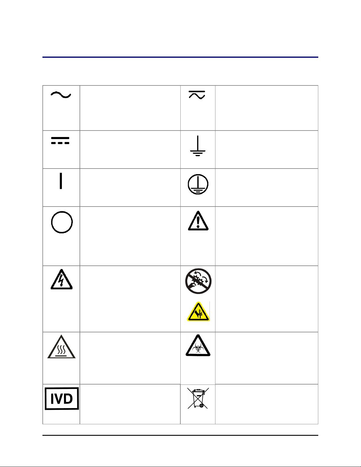
Safety Symbols
Some of these symbols appear on the instrument or accessories:
Alternating current
Courant alternatif
Wechselstrom
Corrientealterna
Correntealternata
Safety Symbols| xix
Both direct and alternating current
Courant continu et courant alternatif
Gleich - und Wechselstrom
Corriente continua y corrientealterna
Corrente continua e
correntealternata
Direct current
Courant continu
Gleichstrom
Corriente continua
Corrente continua
On (Supply)
Marche (alimentation)
Ein (VerbindungmitdemNetz)
Conectado
Chiuso
Off (Supply)
Arrêt (alimentation)
Aus (TrennungvomNetz)
Desconectado
Aperto
(sconnessionedallaretedialimentazio
ne)
Warning, risk of electric shock
Attention, risque de choc électrique
Gefährlicheelektrischeschlag
Precaución, riesgo de
sacudidaeléctrica
Attenzione, rischiodiscossaelettrica
Earth ground terminal
Borne de terre
Erde (Betriebserde)
Borne de tierra
Terra (difunzionamento)
Protective conductor terminal
Borne de terre de protection
Schutzleiteranschluss
Borne de tierra de protección
Terra diprotezione
Caution (refer to accompanying
documents)
Attention (voir documents
d’accompanement)
AchtungsieheBegleitpapiere
Atención (vease los
documentosincluidos)
Attenzione, consultare la doc annessa
Warning, risk of crushing or pinching
Attention, risqued’écrasement et
pincement
Warnen, Gefahr des Zerquetschens
und Klemmen
Precaución, riesgo del
machacamiento y sejeción
Attenzione,
rischiodischiacciareedintrappolarsi
Warning, hot surface
Attention, surface chaude
Warnen, heißeOberfläche
Precaución, superficiecaliente
Attenzione, superficiecalda
In vitro diagnostic medical device
Dispositif médical de diagnostic in
vitro
Medizinisches In-Vitro-Diagnostikum
Dispositivo médico de diagnóstico in
Warning, potential biohazards
Attention,
risquesbiologiquespotentiels
Warnung!
MoeglichebiologischeGiftstoffe
Atención, riesgosbiológicos
Attenzione, rischiobiologico
Separate collection for electrical and
electronic equipment
Les équipements électriques et
électroniques font l’objet d’une
collecte sélective
BioTek Instruments, Inc.
Page 22

xx | MultiFlo FX Operator's Manual
vitro
Dispositivo medico diagnostico in
vitro
Consult instructions for use
Consulter la notice d’emploi
Gebrauchsanweisung beachten
Consultar las instrucciones de uso
Consultare le istruzioni per uso
Getrennte Sammlung von Elektround Elektronikgeräten
Recogida selectiva de aparatos
eléctricos y electrónicos
Raccolta separata delle
apparecchiature elettriche ed
elettroniche
MultiFlo™ FX Multi-Mode Dispenser
Page 23

Chapter 1
Introduction
Thank you for purchasing the MultiFlo™ FX Multi-Mode
Dispenser. This chapter describes the instrument's features
and specifications and includes important contact information.
Introducing the MultiFlo™ FX Dispenser 2
Features of the MultiFlo FX 3
MultiFlo FX Dispenser Comparison 7
BioStack Compatibility 10
Package Contents 12
Optional Accessories 13
Physical Specifications 18
Performance Specifications 21
Space Requirements 25
BioTek's Customer Resource Center 26
Page 24
2 | Chapter 1: Introduction
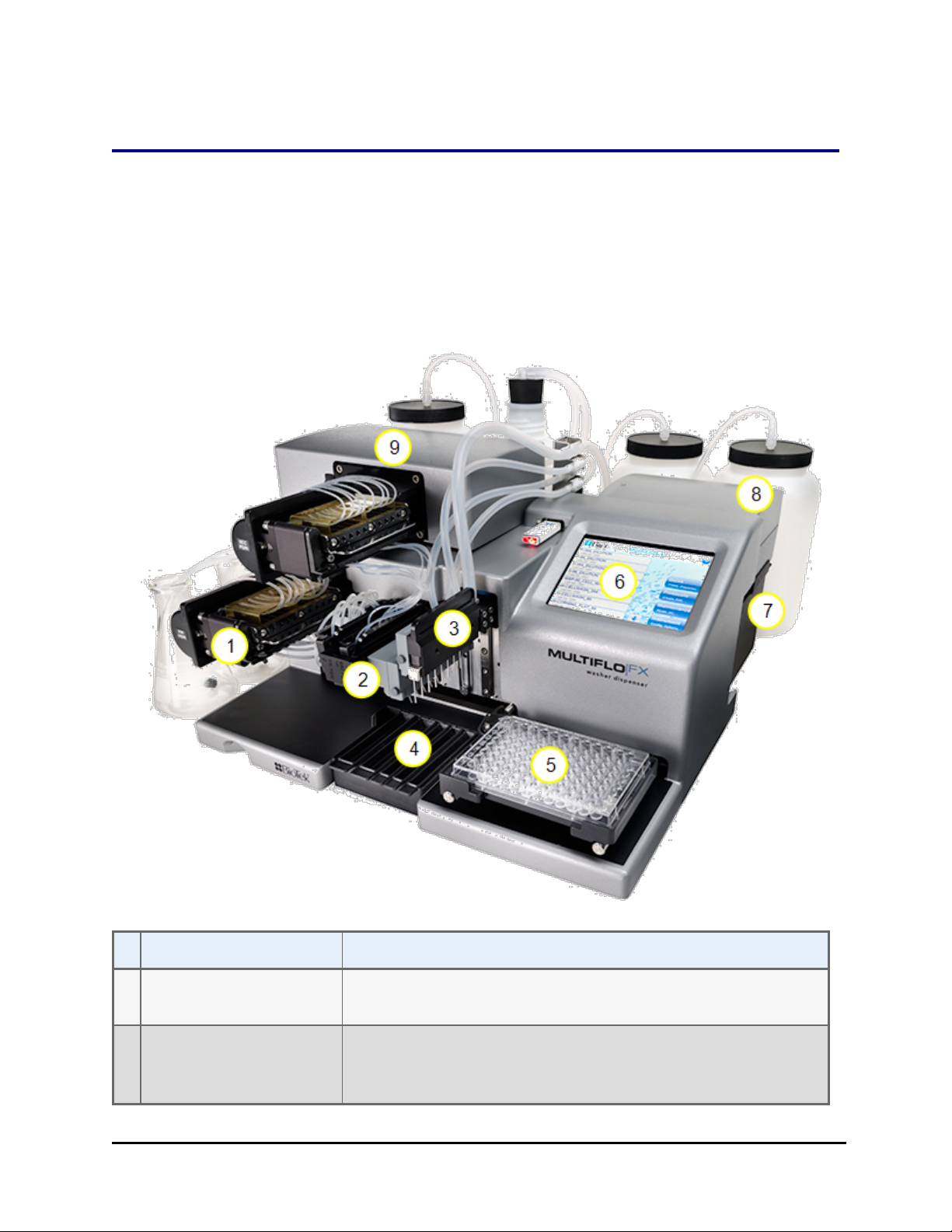
Introducing the MultiFlo™ FX Dispenser
The MultiFlo FX offers several devices in one instrument: one or two peristaltic
pump dispensers called the Peri-pump, a dual Syringe pump dispenser, and either
a strip Washer or a single-channel Random Access Dispenser (RAD) module. The
MutliFlo FX is available in multiple configurations to support numerous
microplate geometries.
Device/Component Description
1 Peri-pump Dispenser Peristaltic, 8-channel dispenser with entirely visible fluid
path.
2 Dispense arm Holds the Peri-pump Tip Holder(s), the Syringe dispenser
manifolds and the washer dispense manifold, when
applicable.
MultiFlo™ FX Multi-Mode Dispenser
Page 25
Features of the MultiFlo FX | 3
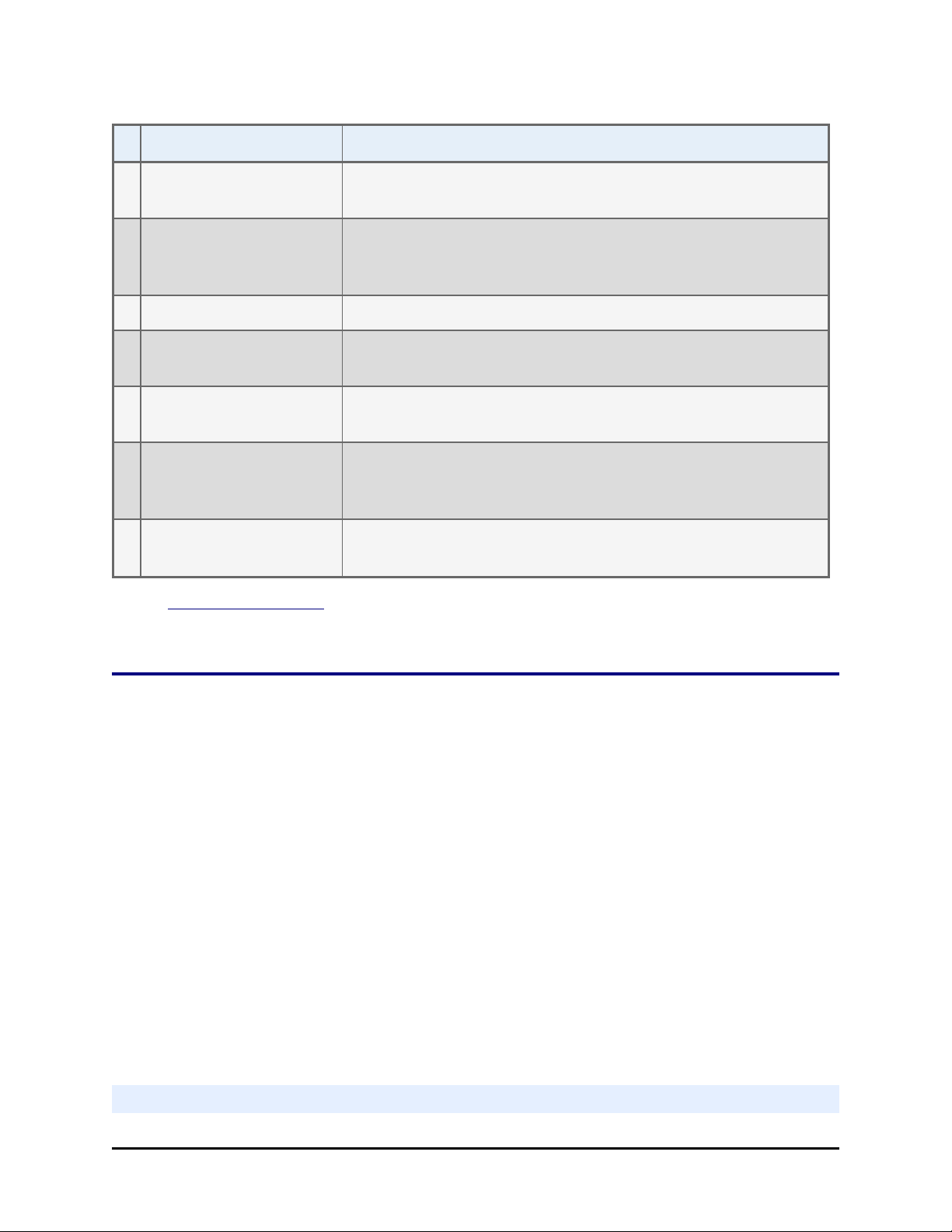
Device/Component Description
3 Aspirate/RAD arm Washer and RAD models only: holds the strip washer's
aspirate manifold or the RAD cassette's tip holder.
4 Priming trough Waste reservoir for collecting or disposing of priming fluid.
Priming trough inserts, for collecting fluid, are shown in this
image.
5 Plate Carrier Holds standard microplates for processing.
6 Touch screen One of two ways to control the MultiFlo FX; the other way is
LHC.
7 Strip Washer An external module containing a syringe-pump dispenser
and vacuum aspiration pump.
8 Syringe Dispenser Another external module with two distinct syringe-pump
dispensers that support a variety of manifold types to
process standard and low-density microplates.
9 Peri-pump Dispenser Secondary or external Peri-pump dispenser (required for
RAD models).
See Plate Types Table on page 9 to review the plate types supported by each
device.
Features of the MultiFlo FX
l Supports all microplate-based assays, including ELISA, fluorescence,
chemiluminescence, RIA, DNA probes, and cellular assays.
l A variety of solutions, including buffered saline and reagents can be dispensed.
l The intuitive onboard software allows you to create and store wash and dispense
protocols. BioTek provides numerous predefined protocols for maintenance and
instrument qualification purposes.
l Two USB flash drive ports facilitate file transfer and storage.
l A low-maintenance design, the result of BioTek’s long history with liquid-handling
instruments.
l Compatible with BioTek’s BioStack™ Microplate Stacker for automated plate processing.
l A robot-accessible carrier that can be interfaced into some robotic systems.
l Computer control using BioTek’s Liquid Handling Control™software (“LHC”).
Washer
BioTek Instruments, Inc.
Page 26

4 | Chapter 1: Introduction
l Programmable dispense volumes, and a wide range of wash options, from gentle
washing for cellular assays to vigorous washing for ELISA.
l A “bottom washing” routine to lower the background absorbance and “crosswise” or
secondary aspiration to reduce residual volumes.
l Supports Wash, Prime, Dispense, and Aspirate steps.
l Several predefined protocols are provided to simplify preventative maintenance, which
should be performed regularly to ensure optimum washer performance.
Peri-pump Dispenser
l A peristaltic pump with eight individual tubes transfers fluid from a supply bottle, or up
to eight different supply bottles, to various vessels. The pump has four rollers over which
the tubing is stretched.
l The tubing is contained in an easy to load and unload cassette that is attached to the
pump head. The pump’s protective cover must be in place to run a dispense routine.
l Three tubing sizes are available: 1 µL, 5 µL, and 10 µL for the most precise dispensing of
volumes from 1 to 30,000 µL and 0.5 µL dispenses when using a 1 µL cassette.
l RAD™ Technology models support "random access dispensing" with several single-
channel cassette options, including a bulk dispensing cassette (8 tubes to one chute) with
flow tracking to minimize turbulence in the wells.
l Autoclavable tubing (steam temperatures and pressures of 121° C and 1 bar
(750 mmHg)) is compatible with 70% ethyl or isopropyl alcohol and 0.5% sodium
hypochlorite (bleach) solution for easy maintenance.
Syringe Dispensers
l The Syringe dispenser has a long-lasting seal that ensures precise and accurate fluid
delivery, as well as reproducibility for repeated dispenses.
l Two syringe pumps support distinct fluid sources and dispense manifolds:
o
16-channel: one tube per well for 384-well plates and two tubes per well for 96well plates.
o
32-channel: one tube per well for 1536-well plates.
o
8-channel (two manifolds in one block): one tube per well for both 96- and 384well plates.
l Autoclavable components can be used with organic solvents and provide easy
maintenance.
l Does not require recalibration
Low-density Microplate-specific Syringe Manifolds
Plate-specific dispense manifolds with angled dispensing for cellular assays:
MultiFlo™ FX Multi-Mode Dispenser
Page 27

Features of the MultiFlo FX | 5
l 6-well plate: 8-channel dispense manifold (4 tubes/well).
l 12-well plate: 9-channel dispense manifold (3 tubes/well).
l 24-well plate: 8-channel dispense manifold (2 tubes/well).
l 48-well plate: 12-channel dispense manifold (2 tubes/well).
Liquid Handling Control™ (LHC) Software
BioTek’s Liquid Handling Control (LHC) software lets you control the instrument
from your computer. You’ll enjoy the convenience of programming assay-specific
wash and dispense protocols in a familiar Windows environment (Microsoft
Windows®7, Windows 8, and Windows XP).
For high-throughput applications, the LHC supports BioStack™ integration.
Please refer to the LHC Installation Guide and Help system to learn about:
o
Installing the LHC software on the controlling computer
o
Running Maintenance protocols
®
o
Running Qualification protocols
o
Special considerations when operating with the BioStack Microplate Stacker
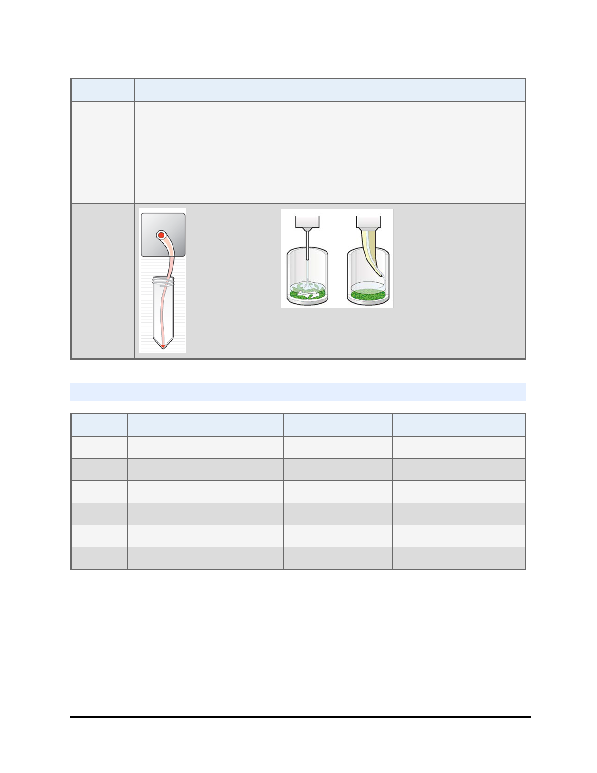
RAD™ Technology Features
Random Access Dispensing or RAD models offer the most gentle dispensing
possible to support sensitive cellular assays. The single-tube cassettes are ideal for
reagent preservation, hit-picking or partial plate filling. The 8-to-1 channel bulk dispensing cassettes are designed to preserve cell monolayers in low-density
plates. An external Peri-pump powers the RAD cassettes, which are not compatible
with the internal Peri-pump.
At a glance:
Features Single-tube 8-to-1 tube
Plate
Types
Cassette
tubing
6- to 384-well 6-, 12-, 24-well
1 µL, 5 µL, or 10 µL 5 µL only
Primary
Uses
Example
Application
Random dispensing in 48-,
96-, and 384-well plates
Dispensing costly reagent lowest dead volume
Fast but gentle dispensing with "Tip Tracking"
Media addition to cells in low-density plates
BioTek Instruments, Inc.
Page 28
6 | Chapter 1: Introduction
Features Single-tube 8-to-1 tube
Other Hit picking: fast, intuitive
selection of individual
wells, rows, or columns;
Access and preserve more
reagent: single tube can
handle minute quantities of
reagent.
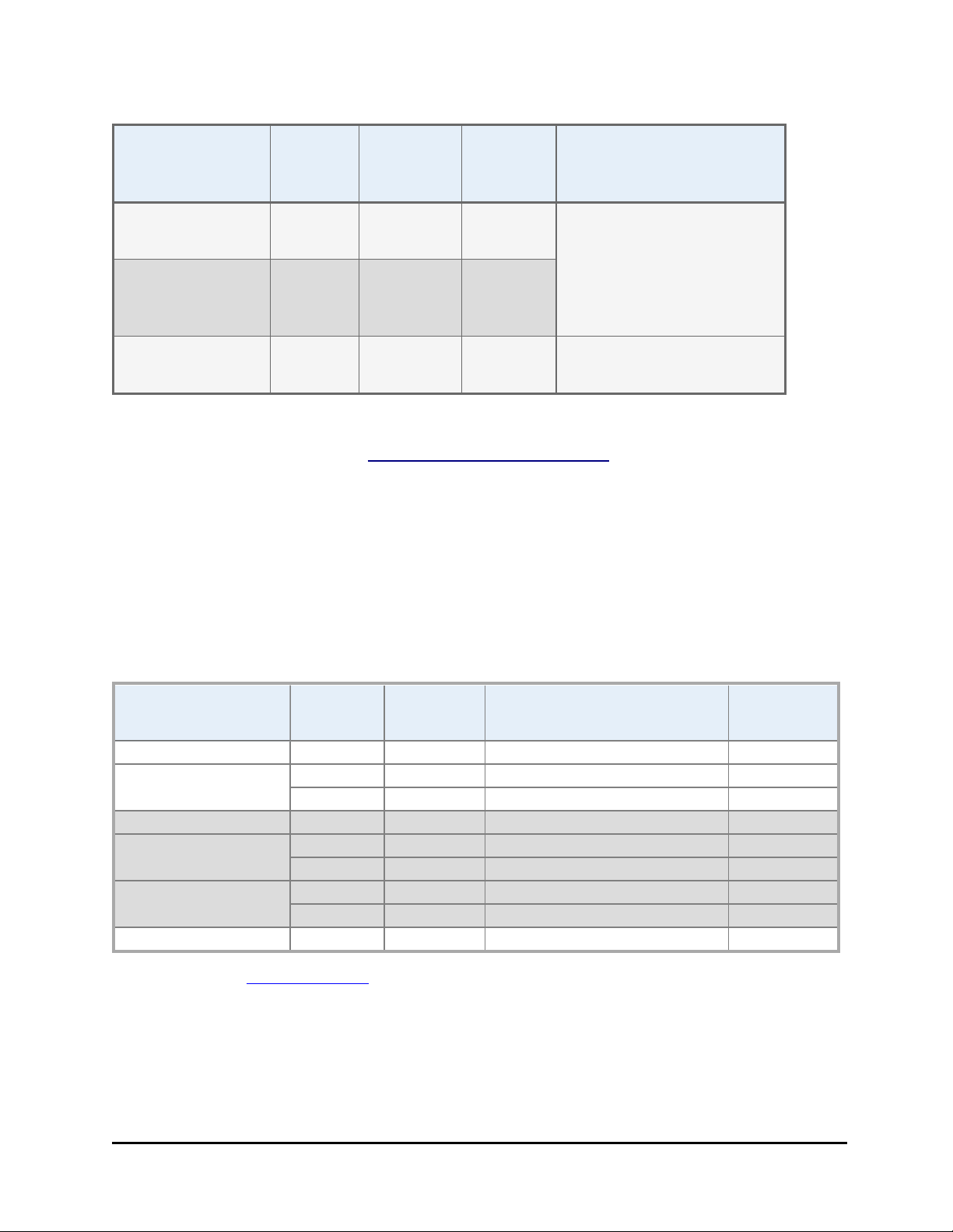
MultiFlo FXModels
Tip Tracking: gradually raises the tip chute as
fluid is dispensed to the well to ensure the least
disturbance possible. See RADTip Tracking on
page 156.
cell monolayer is preserved
Model Internal Peri-pump Strip Washer RAD Technology
MFX
MFXW X
MFXP X
MFXPW X X
MFXR X
MFXPR X X
The Syringe and secondary Peri-pump dispensers are ordered separately. Except
RAD models include the external Peri-pump.
MultiFlo™ FX Multi-Mode Dispenser
Page 29

MultiFlo FX Dispenser Comparison | 7
MultiFlo FX Dispenser Comparison
Counting the washer as a potential dispenser, the MultiFlo FX offers three distinct
dispensers. Here is a comparison of the devices:
n For precious reagents use the Peri-pump to preserve unused fluids. It has
the shortest, most visible fluid path, and a Purge capability to reverse the fluid
flow to recover fluid from the tubing. Another advantage is the ability to
dedicate a dispense cassette to use with one reagent only, reducing the
amount of priming required prior to use. And, you can shorten the tubing to
further reduce the dead volume: See Shorten the Dispense Cassette
Tubing on page 61.
n RAD Technologyoffers the best tools for preserving cells and reagents.
n All MultiFlo FX devices are capable of dispensing up to 30,000 µL. BioTek's
recommended maximum dispense volumes are cited here.
Volume
Device
range
µL/well
Peri-pump 0.5‡, and
1-3000*
RAD
Technology
0.5‡, and
130,000*
Syringe 8-
10-3000 <5% CV @
tube/6-well
Precision Accuracy
<10% CV
@ 1
µL/well
(typical
+/-10%
(typical
+/-3%) @
1 µL/well
<3% CV)
<10% CV
@ 1
µL/well
(typical
+/-10%
(typical
+/-3%) @
1 µL/well
<3% CV)
±2 µL @
20 µL/well
10
µL/well
Approximate Dead
volume
Cassette Type:
1 µL 1.20 mL
5 µL 4.23 mL
10 µL 7.36 mL
Type Dead Vol.
1 µL 150 µL
5 µL 530 µL
10 µL 920 µL
For all manifold types:
12 mL
Syringe 16-tube 5-3000 <10% CV
@ 5
µL/well
±2 µL @
10
µL/well
Syringe 12-/24- 5-30,000 <3% CV @ ±2 µL @
BioTek Instruments, Inc.
Page 30
8 | Chapter 1: Introduction
Volume
Device
/48-well certain
Syringe 32-tube 3-3000 <12% CV
Strip Washer 20 –
*1 µL cassettes' maximum recommended dispense volume is 50 µL/well.
‡ 0.5 µL dispensing is supported when using a 1 µL cassette.
¥Depending on wash manifold, See Performance Specifications on page 21.
range
µL/well
30,000
Precision Accuracy
any
µL/well
@ 6
µL/well
≤3.0 - 5.0
¥
% CV
µL/well
±5% @ 6
µL/well
≤±3.0% 12 mL
Approximate Dead
volume
BioTek recommends priming a dispenser with three times its dead volume to
prepare it for accurate dispensing.
Processing Time
§
Protocols were optimized for speed to obtain the following processing times,
including the fastest flow and travel rates. Some of these parameters are listed in
the Parameters column of the table. Only standard, non-RAD Peri-pump
cassettes are referenced here.
Device Plate
Type
Peri-pump - 5 µL 96 10 High flow rate 3
Peri-pump - 1 µL 384 1 High flow rate 6
1536 1 High flow rate 21
Syringe 8-tube 96 20 Flow rate 1 6.5
Syringe 16-tube 96 20 Flow rate 1 5.25
384 20 Flow rate 1 14
Syringe 32-tube 1536 3 One SB manifold 16.5
1536 14 One LB manifold 27
Strip Washer 96 300 3 cycles <105
Volume
(µL/well)
Parameters Time in
seconds
§ Review the Specifications for more details.
¥ Excluding plate carrier and manifold homing movements.
SB = small bore Syringe manifold; LB = large bore manifold.
¥
MultiFlo™ FX Multi-Mode Dispenser
Page 31

MultiFlo FX Dispenser Comparison | 9
Plate Types Table
Only the Peri-pump can process all plate types. Washer manifolds are named for
plate types they process. Only the 32-tube Syringe dispenser manifolds and the
Peri-pump can dispense to 1536-well plates.
Plate
Height
Columns x
Plate Type
96 Well 12x8 14.35 84 336
96 Deep Well 12x8 41.50 N/A 929
96 Half Well^ 12x8 14.20 84 332
96 Mini Tubes 12x8 49.53 N/A 1105
384 Well 24x16 14.22 64 333
384 Deep Well 24x16 44.08 N/A 986
384 PCR 24x16 9.50 6 230
1536 Well 48x32 10.41 N/A 250
1536 Flanged‡ 48x32 10.26 N/A 196
N/A = Plate washing not supported for this plate type.
Rows
mm Washer Dispensers
Default Aspirate &
Dispense Heights
Low-Density Plates: Peri-pump (non-RAD), Strip Washer, Syringe
Plate
Type
6 Well 3x2 20.20 465 4* 4
12
Well
24
Well
48
Well
Aspirate Ht. default setting = 51 steps (2.07 mm) for all these plate types.
^ Syringe dispenser requires standard 8-channel manifold; washer manifold must be 96/384-well.
‡ Only 1536 Flanged (153F) plates have a "flange height" greater than zero. These plates require
columns
x rows
4x3 20.20 460 2* 3
6x4 20.50 452 2 2
8x6 20.10 460 1* 2
Plate Ht.
(mm)
Dispense Ht.
(steps)
PP tubes/
well
Washer/Syringe
BioTek Instruments, Inc.
tubes/well
¥
Page 32

10 | Chapter 1: Introduction
special handling.
¥
Plate-type specific manifolds: The correct volume-per-tube to meet the specified per-well volume is
dispensed. (Does not apply to non-RAD Peri-pump cassettes!)
*Important: when dispensing to 6-, 12-, 24- and 48-well plates (with a non-RAD cassette) some
dispense tubes must be removed from the Peri-pump's fluid supply vessel. See Handling Special
Plates and Mini-tubes on page 134.
Plate Geometry Diagram
l Plate height = physical measurement
l Default Dispense Height = (plate height - flange height + 1.0 mm)
l Travel Height = (plate height - flange height + Plate Clearance)
n If the Dispense Height is greater than Travel Height, the travel height is
changed to match the dispense height.
BioStack Compatibility
The MultiFlo FX is compatible with BioTek’s BioStack Microplate Stacker. The
BioStack can rapidly transfer microplates one-at-a-time to and from the instrument,
and includes:
l Removable stacks (one input and one output).
l Optional restacking of plates to maintain correct sequencing.
l The ability to continue processing plates following the aborting/failure of
one plate.
l The ability to pause processing to allow the user to add more plates to the
MultiFlo™ FX Multi-Mode Dispenser
Page 33

BioStack Compatibility | 11
input stack or to remove some from the output stack.
l De-lidding and re-lidding capability with BioStack 4.
If you have purchased the BioStack to operate with the MultiFlo FX, refer to the
BioStack Operator’s Manual for instructions on configuring the MultiFlo FX to run
with the BioStack. To help you get started: See Operating with the BioStack on
page 124.
If you are interested in purchasing the BioStack, contact your local BioTek dealer
for more information or visit our website at www.biotek.com.
BioTek Instruments, Inc.
Page 34

12 | Chapter 1: Introduction
Package Contents
n Part numbers and package contents are subject to change and vary according
to instrument model. Please contact BioTek Customer Care if you have any
questions.
Description PN
Power cord (part numbers vary by country of use) Varies
Power supply 76077
RS-232 serial cable 75034
USB cable (USB Virtual COM Port Driver Software & instructions) 75108
Microplate carrier 7170501
Priming trough insert (1 or 2) for Peri-pump 7182043
Priming trough insert for Syringe dispensers (2) and Strip washer
7182044
or RAD dispenser
Strip plate (12x1) 98265
Screwdriver, Phillips 98268
Accessory kit 1260004
Stylus: for cleaning washer and Syringe manifold dispense tubes 2872304
10 cc syringe and tubing for Peri-pump cassette maintenance 7210021
Shipping brackets (2) - model dependent 1262010
1262011
1262115
Hex wrench: 7/64" for removing shipping brackets 48169
Peri-pump Reservoir Holder (2 holders + 4 straps) 7212034
7212035
MultiFlo™ FX Getting Started Guide (and operator’s manual on USB
1261006
- PN 1261000)
n Some components are model specific, they ship only with certain instrument
models.
MultiFlo™ FX Multi-Mode Dispenser
Page 35

Optional Accessories
n Part numbers and package contents are subject to change and vary according
to instrument model. Please contact BioTek Customer Care if you have any
questions.
General Instrument Accessories
Description PN
Optional Accessories | 13
BioTek liquid testing solutions for
instrument qualification tests
Special plate carrier for mini-tubes 7212042
Liquid Handling Control™ Software LHC2
BioStack™ Microplate Stacker and integration kit Biostack
Installation-Operational-Performance Qualification (IQOQ-PQ) package
Wetting
Agent
Blue Test
Dye
7773002
7773001
1260521
Peri-pump Optional Accessories
Secondary Peri-pump assembly: PN 7210010
Dispense cassettes and accessories:
Cassette Type Cassette Tips
Replacement
tubing kit*
Tubing
extension
kit
1 µL plastic tips 7170012 7172150
1 µL 1536-well, plastic tips 7170018 7172150
1 µL sapphire jeweled
stainless steel tips*
1 µL 1536-well, sapphire
jeweled stainless steel tips*
7170015 48692
7170016 48692
7170009 7170022
BioTek Instruments, Inc.
Page 36

14 | Chapter 1: Introduction
Cassette Type Cassette Tips
5 µL plastic tips 7170011 7172059
5 µL stainless steel tips 7170014 7172128
5 µL plastic, large bore tips 7170024 7172039
10 µL plastic tips 7170010 7172059
10 µL stainless steel tips 7170013 7172128
10 µL plastic, large bore tips 7170024 7172039
*Save your stainless steel tips for reuse with a replacement kit, they ship with plastic tips.
RAD‡ Technology Cassettes PN
10 µL Single molded tip 1260015
5 µL Single molded tip 1260016
1 µL Single molded tip 1260017
10 µL Single steel tip 1260018
Replacement
tubing kit*
7170008 7170021
7170007 7170020
extension
Tubing
kit
5 µL Single steel tip 1260019
1 µL Single steel tip 1260021
10 µL Large-bore single molded tip 1260020
Bulk dispenser: 8 tube to 1 chute (5 µL
tubing, molded tips)
1260022
‡Random Access Dispenser (RAD)
Accessory PN
Cassette Calibration Kit 7170017
Peri-pump Reservoir Holder 7210509
40 mL Priming Trough Insert 7182109
Syringe Dispenser Optional Accessories
Accessory PN
Autoclavable Syringe Dispenser Module: 16-Tube Manifold (2) 7180006S
MultiFlo™ FX Multi-Mode Dispenser
Page 37

Optional Accessories | 15
Accessory PN
Non-Autoclavable Syringe Dispenser Module 7210009
Autoclavable Syringe Dispenser Module 7210008
8-Tube (2 x 8 channel) Manifold (1) 7180548S
16-Tube Manifolds (2) 7180543S
32-Tube Small Bore (SB) Manifolds (2) 7180533S
32-Tube Large Bore (LB) Manifolds (2) 7180534S
6-Well-Plate Manifold: 8-tubes (4 tubes/well) 1260537S
12-Well-Plate Manifold: 9-tubes (3 tubes/well) 1260536S
24-Well-Plate Manifold: 8-tubes (2 tubes/well) 1260535S
48-Well-Plate Manifold: 12-tubes (2 tubes/well) 1260534S
Stylus – for cleaning 8-/16-tube dispense manifold tubes 2872304
Stylus – for cleaning 32-tube LB dispense manifold tubes 7182095
Stylus – for cleaning 32-tube SB dispense manifold tubes 7182102
Inline Filters (2) 48705
Hex wrench: 3/32” for removing syringe pumps 48570
Hex wrench: 1/16” for removing magnets from dispense manifolds 48713
Spare tubing sets (2 - 1/dispenser), autoclavable 7183006
DMSO- & Acetonitrile-safe tubing sets (2 - 1/dispenser) 7183002
Special large-bore 8-tube manifold for 96-well plates 7180549S
Strip Washer Optional Accessories
Accessory PN
Fluid Supply Kit 1263007
Waste Bottle and Tubing Kit 1263001
Waste Bottle with Sensor 4070545
BioTek Instruments, Inc.
Page 38

16 | Chapter 1: Introduction
Accessory PN
Spacer Block (substitute for Syringe manifolds) 1262038
Muffler 4073009
Thumb screws 01262
Vacuum Line Filter 48146
Tubing Bracket 1262066
Washer Manifold Kits
Manifold Type Accessory PN
Accessory Kit 1260013
96/384-Well
Dispense Manifold 1262028
Aspirate Manifold 1262029
6-Well Accessory Kit 1260009
Dispense Manifold 1262052
Aspirate Manifold 1262053
12-Well Accessory Kit 1260010
Dispense Manifold 1262050
Aspirate Manifold 1262051
24-Well Accessory Kit 1260011
Dispense Manifold 1262048
Aspirate Manifold 1262049
48-Well Accessory Kit 1260012
Dispense Manifold 1262046
Aspirate Manifold 1262047
Magnetic Bead Assay Accessories
Accessory PN
Magnet Adapter (to support the magnet on the plate carrier) 1262063
Magnets:
MultiFlo™ FX Multi-Mode Dispenser
Page 39

Optional Accessories | 17
Accessory PN
384-well Flat Magnet 7103017
384-well Ring Magnet 7102215
96-well Flat Magnet 7103016
96-well Ring Magnet 7102216
BioTek Instruments, Inc.
Page 40

18 | Chapter 1: Introduction
Physical Specifications
Labware
Microplates 96-well, 384-well, and 1536-well that comply with ANSI/SLAS
microplate standards 1-2004, 2-2004, 3-2004, and 4-2004. 96-well
standard, half-height, deep; 384-well standard, deep, PCR; 1536well standard and flanged. The Peri-pump and plate-type specific
washer and syringe manifolds also support 6- (Corning® 3516), 12(Corning 3513), 24- (Corning 3524), and 48- (Corning 3548) well
plates when special handling instructions are followed. Corning 96Well Cluster Tubes (PN: 4410, 4411), called Mini-tubes in this
application, are supported using a special plate carrier.
Microstrips 1 x 8, 1 x 12
Microwells Flat, round, "V” bottom
Hardware& Environmental
User Interface 5.7" touch screen
Power Supply The instrument uses two internal power supplies: 24-volt 60 watt and
48-volt 60 watt. These supplies are compatible with 100-240 V~; 5060 Hz.
Dimensions
(W x D x H)
Weight (≤) 19.5 lb (8.8 kg)
Operating
Conditions
Relative Humidity The instrument should be operated in a non-condensing humid
Approximately 17.19 x 11.75 x 8.0 inches (44 cm x 29 cm x 20 cm)
base model (without strip washer, external Peri-pump, or Syringe
dispenser).
10° - 40°C (50° - 104°F)
environment having a maximum relative humidity of 80% at
temperatures up to 31°C decreasing linearly to 50% relative humidity
at 40°C.
Peri-Pump
Peristaltic pump: Positive-displacement peristaltic pump with 4 rollers that stretch
the 8 tubes (one per channel) to deliver fluid.
MultiFlo™ FX Multi-Mode Dispenser
Page 41

Physical Specifications | 19
Cassette
Types
1 µL 0.5, 1 - 30,000µL1000 384-well plates @ 5
5 µL 5 - 30,000 µL 1000 96-well plates @ 50
10 µL 10 - 30,000 µL 1000 96-well plates @ 100
Dispense
range
Cassette Life Dead Volume
µL/well
µL/well
µL/well
RAD ™ technology cassettes
Single-tube
(any µL)
8-to-1 tubes
(5 µL)
0.5*, 1 - 30,000µL1 µL: 16,000 wells @ 5 µL
5 µL: 12,000 wells @ 50 µL
10 µL: 12,000 wells @ 100 µL
5 - 30,000 µL N/A 4.2 mL
1.2 mL
4.2 mL
7.4 mL
Type Dead Vol.
1 µL 150 µL
5 µL 530 µL
10 µL 920 µL
* Requires 1 µL tubing
Syringe Dispenser
Two external positive-displacement syringe pump dispensers which support
various manifold types.
Manifold Type
8-Tube 2 x 8-channel non-autoclavable manifold with replaceable stainless
steel tubes to process 96- and 384-well plates.
16-Tube 1 x 16-channel autoclavable manifold with replaceable stainless steel
tubes to process 96- and 384-well plates.
32-Tube 1 x 32-channel manifold cannot be autoclaved, and does not support
non-factory tube replacement. An inline 90-micron filter is included
to minimize clogs. For 1536-well plates only. Two models: large bore
(LB) and small bore (SB).
Plate-Type-Specific Manifolds:
6-Well 1 x 8-channel autoclavable manifold (4 tubes/well) with replaceable
stainless steel tubes to process 6-well plates. Tubes are angled 7
degrees to minimize turbulence in the wells.
12-Well 1 x 9-channel autoclavable manifold (3 tubes/well) with replaceable
BioTek Instruments, Inc.
Page 42

20 | Chapter 1: Introduction
Manifold Type
stainless steel tubes to process 12-well plates. Tubes are angled 7
degrees to minimize turbulence in the wells.
24-Well 1 x 8-channel autoclavable manifold (2 tubes/well) with replaceable
stainless steel tubes to process 24-well plates. Tubes are angled 7
degrees to minimize turbulence in the wells.
48-Well 1 x 12-channel autoclavable manifold (2 tubes/well) with replaceable
stainless steel tubes to process 48-well plates. Tubes are angled 7
degrees to minimize turbulence in the wells.
Supply bottle volume Two 1L bottles: glass for autoclavable models or plastic for
non-autoclavable.
Strip Washer
The external strip washer module uses a non-autoclavable positive-displacement
syringe pump to dispense fluid and a vacuum pump to aspirate fluid. Its dualaction design uses separate, plate-type-specific manifolds for aspirating and
dispensing.
Manifold Type
96/384-Well 1 x 8-channel dispense and aspirate manifolds to process 96- and
384-well plates.
48-Well 1 x 12-channel dispense manifold (2 tubes/well) and 1 x 6-channel
aspirate manifold to process 48-well plates.
24-Well 1 x 8-channel dispense manifold (2 tubes/well) and 1 x 4-channel
aspirate manifold to process 24-well plates.
12-Well 1 x 9-channel dispense manifold (3 tubes/well) and 1 x 3-channel
aspirate manifold to process 12-well plates.
6-Well 1 x 8-channel dispense manifold (4 tubes/well) and 1 x 2-channel
aspirate manifold to process 6-well plates.
Waste bottle volume One 2L vessel; optional accessory includes a waste sensor.
Supply bottle volume Two 2L plastic bottles (non-autoclavable).
MultiFlo™ FX Multi-Mode Dispenser
Page 43

Performance Specifications | 21
Performance Specifications
Peri-Pump Dispenser
Precision is measured for a whole 96-well or 384-well plate (12- or 24-well plate for RAD
technology) using room-temperature deionized or distilled water with 0.1% Tween 20 with
FD&C #1 blue dye. Precision is measured for 1536-well plates by dispensing to 384 wells, 12
columns with a 15% isopropyl alcohol solution. The absorbance of the solution is read at 630
nm and 450 nm reference. Specifications apply to volumes that are full unit increments for the
cassette to which they apply, except the 1 µL cassette also supports 0.5 µL increments when
dispensing this volume. For example: the precision specification for a 10 μL cassette is valid
at 10, 20, 30, ..., 3000 μL; the 1 µL cassette precision specification is valid at 0.5, 1, 2, 3, ...,
30,000 µL.
Accuracy is measured gravimetrically when dispensing room-temperature deionized water.
Specifications apply to volumes that are full unit increments for the cassette to which they
apply. For example: the accuracy specification for a 10 µL cassette is valid at 10, 20, 30, ...
30,000 µL.
Cassette
Precision
Accuracy
1 µL 10%CV @ 1 µL per well ± 10% @ 1 µL per well
5%CV @ 2 µL per well* ± 5% @ 2 µL per well*
10%CV @ 0.5 µL per well n/a
5 µL 5%CV @ 5 µL per well ± 4% @ 5 µL per well
2.5%CV @ 10 µL per well* ± 2% @ 10 µL per well*
10 µL 4%CV @ 10 µL per well ± 4% @ 10 µL per well
2%CV @ 20 µL per well* ± 2% @ 20 µL per well*
* These specifications are for these dispense volumes and higher.
Exception: the accuracy specs above apply to the RAD technology bulk-dispensing cassette, 8
tubes-to-1 (chute) with 5 µL tubing for volumes that are 8 times the full unit increments for
the cassette, e.g. valid at 40, 80, 160, ... 30,000 µL:
l ± 4% when volume is 40 µL/well
l ± 2% when volume is ≥80 µL/well.
BioTek Instruments, Inc.
Page 44

22 | Chapter 1: Introduction
Cassette Expected Lifetime
Cassette Types
1 µL 1000 384-well plates @ 5 µL/well 2,000 mL
5 µL 1000 96-well plates @ 50 µL/well 5,000 mL
10 µL 1000 96-well plates @ 100 µL/well 10,000 mL
Cassette Life
Total Volume
With strict adherence to best practices and maintenance recommendations, this is
the typical longevity of the dispense cassettes.
Syringe Dispensers
Precision is measured for a whole 96-well or 384-well plate using room-temperature
deionized or distilled water with 0.1% Tween 20 with FD&C #1 blue dye. Precision is
measured for 1536-well plates by dispensing to 384 wells, 12 columns with a 15% isopropyl
alcohol solution. The absorbance of the solution shall be read at 630 nm and 450 nm
reference.
Accuracy is measured gravimetrically when dispensing room-temperature deionized water.
Dispense Precision
8-Tube ≤ 2% CV when dispensing 100 µL/well
≤ 5% CV precision at 20 µL/well
≤ 5% CV precision at 40 µL/well **
** Tested in-house to <4.0% CV.
16-Tube ≤ 2% CV when dispensing 100 µL/well
≤ 2.5% CV precision at 80 µL/well***
≤ 5% CV precision at 20 µL/well
≤ 10% CV precision at 5 µL/well*
*unspecified for non-autoclavable syringe pumps.
*** Tested in-house to <1.6% CV.
32-Tube < 12% CV when dispensing 6 µL per tube
Dispense Accuracy
8-Tube Forallvolumes2 µL or 1%, whichever is greater, at flow rate 2.
16-Tube Forallvolumes 2 µL or 1%, whichever is greater, at flow rate 2.
32-Tube ± 5% when dispensing 6 µL/well at flow rate 3.
MultiFlo™ FX Multi-Mode Dispenser
Page 45

Performance Specifications | 23
Low-Density-Plate-Specific Manifolds
Dispense Precision
Refer to the values below for dispense precision when measured in full plates with the
specified volume of deionized water with 0.1% Tween 20 and FD&C#1 blue dye solution
and read at 630 nm/405 nm.
Plate Type Performance Volume (µL/well)
6-Well ≤5.0% CV 5560
12-Well ≤3.0% CV 2240
24-Well ≤3.0% CV 1120
48-Well ≤3.0% CV 560
Dispense Accuracy is measured gravimetrically when dispensing any volume of roomtemperature deionized water using Flow Rate 2. For all plate-specific manifolds, dispense
accuracy shall be 2 µL or 1%, whichever is greater.
Strip Washer
Residual Volume (Evacuation Efficiency)
96Well
6-, 12-,
24-,
48Well
Washer Manifold Volume (µL/well) Travel Rate Residual Volume (µL/well)
Average residual of ≤2.0 µL per well after a 3-cycle wash when dispensing 300
µL per well using a bottom-touching well aspiration and a solution of deionized
water with 0.1% Tween® 20 or equivalent buffer solution. (The aspirate height
adjustment should be optimized for the plate prior to testing.)
Refer to the table below to determine the average residual volume per well after
dispensing the specified µL-per-well using a bottom-touching well aspiration and
a solution of deionized water without Tween in flat-bottomed plates. (The
aspirate height adjustment should be optimized for the plate prior to testing.)
6-well 5560 0 CW 600
12-well 2240 0 CW 150
24-well 1120 0 CW 50
48-well 560 0 CW 25
BioTek Instruments, Inc.
Page 46

24 | Chapter 1: Introduction
Dispense Precision
Refer to the values below for washer dispense precision when measured in full plates with
the specified volume of deionized water with 0.1% Tween 20 and FD&C#1 blue dye
solution and read at 630 nm/405 nm.
Plate Type Performance Volume (µL/well)
96-Well ≤3.0% CV 300
6-Well ≤5.0% CV 5560
12-Well ≤3.0% CV 2240
24-Well ≤3.0% CV 1120
48-Well ≤3.0% CV 560
384-Well ≤3.0% CV 80
Dispense Accuracy
Washer dispense accuracy shall be ≤±3.0% when deionized water with 0.1% Tween 20
(and FD&C#1 blue dye) solution. The weight of the fluid dispensed shall be measured
gravimetrically.
Plate Type Volume (µL/well)
96-Well 300
6-Well 1120
12-Well 2240
24-Well 1120
48-Well 560
384-Well 80
MultiFlo™ FX Multi-Mode Dispenser
Page 47

Space Requirements | 25
Space Requirements
The Physical Specifications on page 18 describe the width (W), depth (D) and height
(H) of the base unit of the MultiFlo FX without an external Peri-pump, Syringe
dispenser, or Washer installed. Likewise, the space required for the bottles, tubing
and power cables is omitted.
Beginning with the base unit dimensions, add space for accessory devices and vessels:
l Expect a depth of 20" (51 cm) when installing a Strip washer and/or Syringe dispenser to
the back. Similarly, expect to add 8" (20 cm) to the depth when installing the RAD
technology dispenser.
l Add 4"-5" to the depth or width for fluid supply and waste bottles, depending on
placement.
l Plan on a height of approximately 12" (31 cm) when installing the washer: the waste
bottle is the tallest accessory, or (if the waste bottle resides elsewhere) at least 10" to
accommodate the washer tubing bracket.
l When an external Peri-pump or Syringe dispenser is installed on top, the height
increases to about 10", which is required for RAD™ technology.
BioTek Instruments, Inc.
Page 48

26 | Chapter 1: Introduction
l Increase the width requirement to include the side tubing bracket and/or supply vessels.
l BioStack integration requires a width of at least 34" in the standard 90° interface. Find
more details in the BioStack Operator's Manual.
BioTek's Customer Resource Center
BioTek's Customer Resource Center (CRC) continues our tradition of superior
service and support. After an easy registration process, you can access lots of
useful information about your BioTek microplate instrumentation and software. On
the secure CRC website, you can:
l Track orders
l Access warranty information, user manuals and software updates
l Download technical and application information
l Maintain equipment inventory (product registration)
l Request service and technical support
l View service history
l And much more!
Register at https://customer.biotek.com
n Dispense cassette data sheets are available for download at the CRC.
MultiFlo™ FX Multi-Mode Dispenser
Page 49

Chapter 2
Installation
This chapter provides detailed installation instructions.
Unpack and Inspect the Instrument 28
Install the Waste Tubing 29
Remove the Shipping Hardware 31
Set up the Strip Washer 34
Set Up the Peri-pump Dispenser 44
Install the Secondary Peri-Pump 46
Install RAD Technology Components 51
Install the Syringe Dispenser Component 62
Install Software/Connect to Computer 71
Connect Power Cable 72
Define Instrument Settings 73
Verify Performance 79
Repacking the MultiFlo FX 82
Install the Shipping Hardware 83
Repacking the Secondary Peri-pump 85
MultiFlo FX Repacking 86
Repacking the Syringe Dispenser 89
Repacking the Strip Washer 90
Page 50

28 | Chapter 2: Installation
Unpack and Inspect the Instrument
Important: Save all packaging materials. If you need to ship the instrument or
accessories to BioTek for repair or replacement, you must use the original packaging.
Using other forms of commercially available packaging is not recommended and can void
the warranty. Improper packaging that results in damage to the instrument may lead to
additional charges. Refer to the operator's manual for repacking instructions.
Inspect the shipping box, packaging, instrument, and accessories for signs of
damage.
If the MultiFlo™ FX Multi-Mode Dispenser is damaged, notify the carrier and your
BioTek representative. Keep the shipping cartons and packing material for the
carrier’s inspection. BioTek will arrange for repair or replacement of your
instrument immediately, before the shipping-related claim is settled.
1. Unpack the boxes containing the instrument and other equipment:
l MultiFlo™ FX Multi-Mode Dispenser and accessories
l Strip Washer and accessories
l Dual Syringe Dispenser and accessories
l Additional Peri-pump Dispenser and accessories, including RAD™
technology components, if applicable.
2. Place all packing materials back into the shipping boxes for reuse if necessary.
3. Syringe Dispenser models: when the Syringe dispenser is a component of your
instrument, review the placement options for it (as described on page 63) and decide
which one best suits your lab before proceeding with the installation.
Refer to the Package Contents on page 12 to make sure you have all expected
equipment.
MultiFlo™ FX Multi-Mode Dispenser
Page 51

Install the Waste Tubing | 29
Install the Waste Tubing
A length of tubing and a bracket to hold it is provided to drain the priming trough
into a waste container. It's safer to perform this task before removing the shipping
hardware.
Underside of MultiFlo showing priming trough waste tubing
Important note: The waste
tubing must lay flat to
properly drain the priming
trough. The side bracket
provided with the instrument
supports this goal, but it may
not be needed in your lab,
depending on where you
position the dispenser and its
waste receptacle.
You will need:
l Philips head screwdriver (small)
l Waste tubing: 4' provided (PN 7213010)
l Possibly scissors or knife to cut tubing to desired length
l Side bracket provided
l Waste vessel: to capture discarded fluid
To install the tubing:
Install Side Bracket for Waste Tubing
BioTek Instruments, Inc.
Page 52

30 | Chapter 2: Installation
1. Turn instrument onto its back to access its
underside.
2. Remove the two screws in the lower left
corner. You will use them to install the
bracket.
3. Align the side bracket with the screw holes
so its hook opens towards you and use the
screws to install the bracket.
You may or may not use the side bracket, depending on where you place the waste
vessel.
Attach the Tubing to the Priming Trough
1. Thread the waste tubing under the
bracket and onto the priming trough's
spout.
Remove the bracket and/or use water or
alcohol to help the tube slide onto the spout.
2. Snake the tubing around the
instrument to the side bracket.
3. Return the instrument to normal
position.
Position Waste Container and Tubing
When all the installation steps are completed:
1. Place the waste container under the instrument's work surface.
2. Position the waste tubing to drain into the waste container, cutting it to the
optimal length, if necessary.
Next, remove the shipping hardware.
MultiFlo™ FX Multi-Mode Dispenser
Page 53

Remove the Shipping Hardware | 31
Remove the Shipping Hardware
Two shipping brackets (and a rubber band when a Peri-pump is included) protect
the MultiFlo FX during shipping. After installing the waste tubing for the priming
trough, place it upright on a level work surface to remove the shipping hardware.
(Store the shipping brackets on the back of the instrument in slots provided for this
purpose.)
You will need:
l Allen (or hex) wrench taped to plate carrier.
The shipping hardware is slightly different than shown above for MultiFlo FX
BioTek Instruments, Inc.
Page 54

32 | Chapter 2: Installation
without a washer or RAD technology:
For these
MultiFlo FX
models:
l MFX
l MFXP
First remove the
plate carrier
shipping bracket
and then remove
the dispense arm
bracket.
Reverse this
order when
reinstalling the
brackets (before
shipping): put the
dispense arm
bracket on the
post first.
Remove shipping brackets:
1. Remove the plate carrier shipping bracket: use the Allen wrench to remove the
two screws that hold it to the plate carrier. Tilt the bracket downwards slightly,
and release it from the post.
2. Remove the dispense arm shipping bracket: use the Allen wrench to remove the
two screws that hold the bracket to the instrument.
3. Attach the shipping brackets to the back of the instrument for storage. They will
be needed if the dispenser must be shipped in the future.
MultiFlo™ FX Multi-Mode Dispenser
Page 55

Remove the Shipping Hardware | 33
Dispense-arm bracket for
MultiFlo FX without a washer or
RAD technology
4. Insert the brackets into their respective slots on the back of the instrument, in
lower right corner. Slide the plate-carrier bracket's longest arm into the slot and
use the Allen wrench to screw it in place. (Exception: The dispense-arm bracket
for MFX and MFXP models does not fit into a slot. Attach it with one screw so
the short end projects out from the instrument. You must first remove the large
support bracket attached to the back panel that is used for an external Peripump. Insert the second screw next to the bracket.)
Store the Allen wrench for future use.
BioTek Instruments, Inc.
Page 56

34 | Chapter 2: Installation
Set up the Strip Washer
Perform these steps:
l Attach washer module and connect its cable on the facing page,
l Install the tubing bracket on page 37,
l Install the Fluid Supply on page 38,
l Install the Waste Bottle on page 39,
l Install the muffler on page 41,
l Install Washer Manifolds on page 41.
Strip Washer accessories
Provided with the strip washer module:
Part Part Description
Aspirate manifold: install on dedicated
aspirate arm. Press the stainless steel tab on
the front of the arm to install (and to remove)
the manifold.
Install this manifold last, after installing
items on the dispense arm.
See Install Washer Manifolds on page 41
Dispense manifold: install on the dispense
arm after installing either the Syringe
dispenser manifolds or the spacer block.
n Several plate-type-specific
manifold sets are offered.
Part
Number
1260510
for 96/384well
(shown)
1260511
for 96/384well
(shown)
MultiFlo™ FX Multi-Mode Dispenser
Page 57

Set up the Strip Washer | 35
Part Part Description
Muffler:install on exhaust tubing to reduce
instrument noise. Finger-tighten only.
Spacer block: to properly position washer
manifolds when the dual Syringe dispenser is
not installed. Put the spacer on the dispense
arm before installing the washer dispense
manifold (in lieu of Syringe dispenser
manifolds).
Thumb screws: to secure dispense manifold
to dispense arm. Especially useful when
performing magnetic bead assays. See
Special Procedure for Magnetic Bead
Assays on page 151.
Part
Number
4073009
1260522
01262
Tubing bracket: to hold tubing in place. 1262066
Vacuum Line Filter: cut the vacuum line
tubing and install the filter to prevent
contaminates from clogging the vacuum pump.
See also Strip Washer Optional Accessories on page 15 for part numbers for
48146
plate-type-specific washer manifolds.
Attach washer module and connect its cable
The MultiFlo FX's optional strip washer is positioned on posts and attached to the
back of the instrument. A bracket holds the fluid supply and waste tubing, keeping
BioTek Instruments, Inc.
Page 58

36 | Chapter 2: Installation
the tubing secure and away from moving parts.
You need a Philips screwdriver.
1. First, remove the screws and
washers that will attach the washer
to the back panel.
2. Align the slots on the side of the
washer module with the two posts
near the base. Simultaneously,
align the screw holes on the top of
washer unit.
3. Use the screws removed in the first
step to attach the module to the
instrument.
4. Connect the serial cable from the
washer module to its port on the
back of the instrument.
back panel
MultiFlo™ FX Multi-Mode Dispenser
Page 59

Set up the Strip Washer | 37
The washer module functions as a shelf for a Syringe dispenser, if desired.
Install the tubing bracket
A stainless steel bracket to keep the tubing away from
moving devices is provided with the washer and RAD
models.
Attach the bracket to the back of the instrument: near the
top, center of the instrument, slightly left of the aluminum
mounting plate as you face the back panel.
You need a small Philips screwdriver.
1. First, remove the two screws you will use to attach
the bracket. Refer to the photo below to locate the
screws on the back of the instrument.
2. Align the bracket to the holes and use the screws to
attach it.
BioTek Instruments, Inc.
Page 60

38 | Chapter 2: Installation
The tubing bracket is designed to snugly hold the check valves of the fluid supply
tubing and the waste tubing's rigid valve.
Install the Fluid Supply
The strip washer's fluid supply
system (PN 1263007) uses a
two-liter plastic supply vessel
and two tubes with check valves,
powered by a non-autoclavable
syringe pump.
1. Locate the tubing with the Luer fitting on one end. Gently screw the Luer fitting
into its connection on the top of the supply bottle. Finger-tighten only.
2. Attach the other end of the fluid supply tubing to the bottom port of the washer
pump. Make sure the arrow on the check valve points towards the pump.
3. Connect the tube without fittings to the top port of the washer pump. Make
MultiFlo™ FX Multi-Mode Dispenser
Page 61

Set up the Strip Washer | 39
sure the arrow on the check valve points away from the pump.
4. Connect the other end of the tube to the dispense manifold.
Fluid supply installed
When you're ready, snake the tubing from the devices mounted on the
back of the instrument to the manifolds on the front: put the supply
tubing check valves and the rigid fixture of the waste tube in the
center of the bracket.
As part of the setup: Install Washer Manifolds on page 41.
Install the Waste Bottle
The washer collects waste fluid during aspiration. The waste bottle is connected to
the vacuum pump (inside the washer module) and the aspirate manifold to
perform this function.
An inline vacuum filter (not shown) is optional but strongly recommended because
(1) the filter prevents waste material aerosols from being released into the air, and
BioTek Instruments, Inc.
Page 62

40 | Chapter 2: Installation
(2) the filter serves as a temporary fluid barrier in the event that the waste bottle is
allowed to overfill. (The filter part number is 48146.)
An optional Waste Sensor bottle, PN 4070545, alerts users to the need to empty the
waste container, preventing overflow problems.
1. Remove the waste bottle cap and replace it with the stopper from the waste
tubing set (PN 1263001).
2. Connect the tube without a fitting to the aspirate manifold.
3. Install the inline vacuum filter on the tubing with a Luer fitting:
o
Cut the tubing about two inches from the Luer fitting,
o
insert the filter to reconnect the tubing.
4. Gently screw on the Luer fitting to the port labeled Vacuum.
5. If applicable, connect the waste sensor cable to the Waste Sensor port and
enable the sensor:
Using the Touch screen Using the LHC
1. Select Instrument>Washer. 1. Select Tools>Instrument
MultiFlo™ FX Multi-Mode Dispenser
Page 63

Using the Touch screen Using the LHC
Set up the Strip Washer | 41
2. Touch the field to enable Waste
detection under Sensors Enabled.
3. Press the Home button.
Install the muffler
Utilities.
2. Under Strip Washer, fill the
checkbox to enable Waste
Detection.
3. Click Send, and then, Exit.
Install the optional vacuum pump muffler (PN 4073009) to reduce noise during
operation: Connect the muffler's Luer fitting to the Exhaust port. Finger tighten,
only.
Install Washer Manifolds
The strip washer has two distinct manifolds: the dispense manifold resides on the
dispense arm, along with the Peri-pump cassette's Tip Holder and the dual Syringe
dispensers manifolds, if equipped. The aspirate manifold resides on its own
dedicated aspirate arm.
Important: Either the dual Syringe dispenser manifolds or the spacer block must be
installed on the dispense arm before the washer dispense manifold can be installed. And,
the washer dispense manifold must be installed before the aspirate manifold is installed.
1. Turn off the MultiFlo FX, if
necessary.
2. Connect the fluid supply tubing
Install the Fluid Supply on page 38
to the dispense manifold.
Install the Waste Bottle on page 39
BioTek Instruments, Inc.
Page 64

42 | Chapter 2: Installation
3. Connect the waste vessel tubing
to the aspirate manifold.
4. Lower the aspirate arm to gain
access to the dispense arm, if
necessary, i.e. move it out of the
way.
5. First, install either the Syringe
dispenser manifolds or the
spacer block on the dispense
arm:
l orient the block so its lip
points down and abuts the
dispense manifold;
l position the Syringe
manifold's tubing closest to
the instrument.
Typically, magnets hold them
securely.
6. With its supply tube closest to
the instrument, guide the
dispense manifold onto the
dispense arm. Its magnet will
hold it securely. Alternatively,
especially when running
magnetic bead assays, remove
the magnet and use the thumb
screws provided. Special
Procedure for Magnetic Bead Assays
on page 151.
7. Lift the aspirate arm to its
highest position. Align the two
pins on the aspirate manifold
with the holes on top of the arm,
and press the "Aspirate arm
release tab" to install the
aspirate manifold.
MultiFlo™ FX Multi-Mode Dispenser
Page 65

Set up the Strip Washer | 43
Install the
Syringe
Dispenser
manifolds on the
dispense arm
instead of the
"Spacer block,"
if applicable.
To remove the washer manifolds:
Reverse the order of the installation steps, i.e. first remove the aspirate manifold: press
the release tab. Then, remove the dispense manifolds.
BioTek Instruments, Inc.
Page 66

44 | Chapter 2: Installation
Set Up the Peri-pump Dispenser
Install these items to use the Peri-pump dispenser:
l Install the external Peri-pump, if applicable
l Install RAD Technology Components
l Or, attach the Peri-pump cover panel
l Dispense cassette
l Fluid supply vessel
l (Optional) Prime trough insert
Attach the Peri-pump Cover Panel
Optionally, if you are not installing an external (or secondary) Peri-pump, install
the cover panel provided to conceal the primary Peri-pump.
Install the cover panel using the two hex screws and the Allen wrench shipped with
the MultiFlo FX.
MultiFlo™ FX Multi-Mode Dispenser
Page 67

Set Up the Peri-pump Dispenser | 45
MultiFlo FX with closed Peri-pump cover panel
BioTek Instruments, Inc.
Page 68

46 | Chapter 2: Installation
Install the Secondary Peri-Pump
An optional secondary or external Peri-pump dispenser is available for the
MultiFlo FX. It ships as a kit with its own accessories and it is required for RAD™
technology. Inspect and unpack the shipping container and follow these installation
instructions if applicable. Otherwise, skip this part of the installation process.
The secondary Peri-pump is designed to sit on top of the MultiFlo FX, above and
slightly right of the internal Peri-pump.
MultiFlo™ FX Multi-Mode Dispenser
Page 69

Install the Secondary Peri-Pump | 47
Kit components include:
l 1 - additional Peri-pump
l 2 - small tab to secure unit to the instrument
l 3 - additional dispense cassette bracket
l 4 - interface cable to connect unit to the instrument
l 5 - MultiFlo FXOnly: extra stainless-steel bracket to replace #2
l Also note the screwdriver, Allen (hex) wrench, and shoulder screw shipped with
the accessories.
You will need:
l Second Peri-pump Kit components (shown above)
l Philips head screwdriver (small)
l Small flat screwdriver
Install the additional Peri-pump:
MultiFlo FX ONLY: Change the bracket on the
front of the Secondary Peri-pump unit:
l Remove the black plastic tab and replace
it with the stainless-steel bracket
shipped in the kit, using the same
screws. (See #5 above.)
BioTek Instruments, Inc.
Page 70

48 | Chapter 2: Installation
1. First, remove the support bracket
stored on the back of the instrument.
It will be used to secure the
dispenser on top of the instrument.
Remove the two screws holding the
bracket in place.
2. Two more screws needed for the
installation are shipped on the back
of the Peri-pump unit. Remove the
two screws and keep with the
bracket.
3. Place the second Peri-pump unit on
top of the dispenser.
4. Position the dispenser so the screw
hole in the small tab or stainlesssteel bracket attached to its front
aligns with the right-hand screw
hole on the primary Peri-pump or
cover plate.
5. Use the Philips screwdriver to fully
tighten the shoulder screw to ensure
the unit is secured.
6. On the back of the instrument,
secure the Peri-pump unit in place
MultiFlo™ FX Multi-Mode Dispenser
The support bracket can be installed two
ways, to provide foot holds for a Syringe
dispenser module, or not.
Page 71

Install the Secondary Peri-Pump | 49
with the support bracket and the
four screws removed from the
instrument earlier. Partially tighten
Hide the bracket's foot holds inside the case
when a Syringe dispenser will not be
installed on top of the second Peri-Pump.
the screws until all 4 are in place,
then tighten all the screws.
Install the additional dispense cassette bracket:
This task is easier to perform when the cassette bracket is well lit. It's a tight space and
the second cassette bracket fits snugly onto the original bracket.
1. First, remove the four screws and
washers from the additional cassette
bracket using the small Allen
wrench supplied in the kit.
2. Slide the plate carrier to the left, out
of the way. Lower the dispense arm
to a workable position.
3. Use the text on the front of the
additional cassette bracket to orient
it correctly and place it around the
original bracket.
4. Use the four screws to secure the
bracket over the existing bracket.
Place and partially tighten the
screws until all four are in place,
then tighten all the screws.
BioTek Instruments, Inc.
Page 72

50 | Chapter 2: Installation
Install cable to connect the dispenser:
1. On the back of the instrument,
connect the interface cable to the
Peri-pump Dispenser port on the
back of the instrument and to the
port on the back of the Peri-pump
unit. Use the small flat screwdriver
to secure the cable.
n If you are installing a Syringe dispenser also, you may find it easier to
complete that installation before connecting the cable, turning on the
instrument, and installing the dispense cassettes.
MultiFlo™ FX Multi-Mode Dispenser
Page 73

Install RAD Technology Components | 51
Install RAD Technology Components
Perform these installation steps for the RAD technology Peri-pump dispenser, if
applicable. Otherwise, skip this section.
RAD™ Technology Components
1 - Secondary
or external
Peri-pump
2 - RAD
dispense head
(with ribbon
cable)
3 - RAD
module and
thumbscrew
4 - Tubing
bracket
5 - Cables (2)
RAD technology uses the secondary or external Peri-pump dispenser, a tubing
bracket, and a dedicated dispense head. After removing and storing the shipping
hardware, install these components:
l Install the Secondary Peri-Pump on page 46
l Install the Tubing Bracket and RADModule below
l RAD: Plug in the cables on page 53
l Install RAD Dispense Head on page 53
l Install RAD Technology Cassette on page 58
Install the Tubing Bracket and RADModule
First, install the tubing bracket and then attach the small RAD module with a serial
port to the bracket.
BioTek Instruments, Inc.
Page 74

52 | Chapter 2: Installation
Install the tubing bracket
A stainless steel bracket to keep the tubing away from
moving devices is provided with the washer and RAD
models.
Attach the bracket to the back of the instrument: near the
top, center of the instrument, slightly left of the aluminum
mounting plate as you face the back panel.
You need a small Philips screwdriver.
1. First, remove the two screws you will use to attach
the bracket. Refer to the photo below to locate the
screws on the back of the instrument.
2. Align the bracket to the holes and use the screws to
attach it.
Attach the RADModule to the Tubing Bracket
View of inside the tubing bracket
MultiFlo™ FX Multi-Mode Dispenser
Page 75

Install RAD Technology Components | 53
1. First, remove the thumbscrew and bolt shipped on the tubing bracket.
2. Use the thumbscrew to attach the RAD module to the tubing bracket.
RAD: Plug in the cables
Plug the cables into their respective ports:
l RAD module to Washer Module port
l Peri-pump to Peri-Pump Dispenser
port
Install RAD Dispense Head
The RAD dispense head resides on the dedicated Aspriate manifold/RAD arm. Its
ribbon cable plugs into the RADmodule (installed in earlier step).
1. Align the two pins on the dispense
head with the two holes on the
RADarm, and press the Release Tab
(on the front of the arm) to install the
dispense head.
BioTek Instruments, Inc.
Page 76

54 | Chapter 2: Installation
2. Plug the ribbon cable on the dispense
head into the RAD module (installed
on the tubing bracket).
Next, install the RADcassette: Install RAD Technology Cassette on page 58.
Dispense Cassette Diagram
1
2 - Center Holder
3 - Tube Tensioner
4 - Tubing Organizer
5 - Tip Guard
(remove before use)
- Tip Holder
MultiFlo™ FX Multi-Mode Dispenser
Page 77

Install RAD Technology Components | 55
Tubing Cassette Diagram
RAD™ Technology tips replace #1 Tip Holder when installing the
cassette.
1. Tip Holder: The cassette’s easiest part to identify, the tip holder fits into the
dispense arm to the right of the pump for positioning above the plate. Except
RAD technology cassette tips fit into a dedicated dispense arm.
2. Center Holder: The center holder is labeled to identify the size of the cassette
tubing. It also has a serial number for tracking purposes. It slides into grooves
on the underside of the pump.
3. Tube Tensioner: The transparent 5-mm scale on its front surface identifies the
tube tensioner. It has internal screws for stretching the tubing, one for each
tube. The tube tensioner’s scale is useful when calibrating the cassette.
4. Tube Organizer: At the opposite end of the cassette from the tip holder, the
tube organizer holds the 8 tubes together for inserting into the fluid vessel.
Except it is omitted from the single-tube cassettes.
5. Tip Guard: Remove the tip guard before installing the cassette. The tip guard
protects the tips during shipping. It is not a permanent part of the cassette. The
RAD single-tube cassette also ships with a tip guard.
BioTek Instruments, Inc.
Page 78

56 | Chapter 2: Installation
Install the Dispense Cassette
Prerequisites:
o
Review the Dispense Cassette Diagram on page 54 to learn the names of the
components.
o
Move the Pump Cover away from the pump to its OFF position.
o
When you have two Peri-pumps installed, put the Primary pump's Tip Holder in the
left bracket and the Secondary pump's Tip Holder in the right bracket.
o
Release the pump’s stainless steel plate: Use your right hand to release the
spring-loaded cassette latch (on the right side of the caution symbol on the pump)
and use your left hand to lift the stainless steel plate up and out.
The BioTek logo on the Tip Holder faces the Peri-pump. The logo on the Center Holder
faces down, away from the pump.
Note: See Install RAD Technology Cassette on page 58 for single-tube and bulk
cassette instructions.
MultiFlo™ FX Multi-Mode Dispenser
Page 79

1. Slide the Tip Holder into the
dispense arm. The Tip Holder’s
front plate with the BioTek logo
or steel plate faces the pump.
Make sure the tip holder is level
and snapped into place.
l Two Peri-pumps: use left bracket for
Primary, right bracket for
Secondary.
l RAD technology exception: attach
the tip holder to the dedicated
dispense head.
2. Extend the rest of the cassette
under the Peri-pump, so you
can slide the Center Holder into
its slot on the underside of the
pump. A tab on the back of the
center holder fits into a notch
on the pump. The label on the
center holder faces down.
Install RAD Technology Components | 57
3. Align the Tube Tensioner with
the stainless steel plate as it
wraps around and up against
the pump. Be sure the knobs on
top of the tensioner fit correctly
into the grooves in the stainless
steel plate as you move both
parts up and around the pump
and click the steel plate into
place.
4. Return the Pump Cover to its RUN position covering the pump.
5. Lift the Tube Organizer over the pump cover. Place it in the fluid vessel, when
you’re ready.
BioTek Instruments, Inc.
Page 80

58 | Chapter 2: Installation
Install RAD Technology Cassette
RAD technology's single-tube and 8-to-1 bulk dispensing cassettes are installed like
standard cassettes with one difference, the tip holder is installed on the dedicated
RAD dispense head. Install the RADcassettes on the external or secondary Peripump only! They are not designed for use on an internal Peri-pump.
Follow instructions to Install the Dispense Cassette on page 56 skipping the first step.
Magnets on the dispense head hold the cassette tip(s) in place:
Single tube RADcassette 8-tube-to-1 Bulk RADcassette
Align the two pins with the holes (above and below the magnets) on the dispense
head.
n You must create a protocol to successfully use the RAD8-to-1 bulk-dispensing
cassette. It is not compatible with Quick Dispense.
MultiFlo™ FX Multi-Mode Dispenser
Page 81

Prime Trough Inserts
Install RAD Technology Components | 59
The MultiFlo FX ships with special reservoirs that fit into the dispensers’ priming
trough to capture expensive reagent after priming, rather than discarding it.
Three types of Prime Trough Inserts may be provided:
l PN 7182043 for the Peri-pump dispenser, holds approximately 12 mL (1 per
dispenser)
l PN 7182044: 2 for the Syringe dispensers, 1 for the washer, holds
approximately 6.5 mL
n Without the prime trough insert, the priming trough empties into the regular
waste bottle.
Important: Remove the priming trough inserts when using the 8-to-1 RAD cassette.
The chute will collide with both the RAD priming cup and the Syringe dispenser insert if they
are left in the priming trough.
BioTek Instruments, Inc.
Page 82

60 | Chapter 2: Installation
Peri-pump Reservoir Holder
MultiFlo FX models with a
Peri-pump dispenser
include the convenient Peripump reservoir holder (PN
7210509). The simple bracket
clips onto the front of the
Peri-pump to hold a variety
of vessels.
You can significantly reduce
the dead volume, saving
precious fluid, by cutting
the cassette tubing to make a
shorter fluid path. See
Shorten the Dispense
Cassette Tubing on the
facing page.
Peri-pump Reservoir Holder attached to Peri-pump
The reservoir holder has two components, a bracket and
a strap.
1. Clip the bracket onto the front of the Peripump. When properly installed the bracket
hides the hazard label.
2. Place the supply vessel (reservoir) on the
bracket and wrap the strap around both the
vessel and the bracket: fit the strap's molded
balls into the round slots.
Depending on the size of the vessel, it may be necessary to tuck the ends of the
strap into the bracket, too, to keep the slack out of the way.
n Important: Always remove the tubing from the fluid before releasing the
tension on the cassette or changing cassettes.
MultiFlo™ FX Multi-Mode Dispenser
Page 83

Install RAD Technology Components | 61
Shorten the Dispense Cassette Tubing
Shortening the fluid path reduces the dead volume when dispensing, which helps
preserve expensive reagents. BioTek offers the Peri-pump Reservoir Holder on the
previous page as an accessory to the Peri-pump dispenser for this purpose. The
cassette tubing can be shortened by as much as 12 inches (30.48 cm) when using the
reservoir holder.
Recommendations for cutting the tubing:
l Prepare a clean, lint-free work area to lay out the cassette;
l Remove the Tube Organizer (not applicable to RAD single-channel cassette);
l Use a ruler as a guide to determine where to cut the tubing;
l Cut one tube at a time using a razor blade, Exacto
clean a cut as possible;
®
knife, or sharp scissors; make as
l Cut the tubing as evenly as possible, limiting the difference between the tubes to less
than 1/4" (6.35 mm) (not applicable to RAD single-channel cassette).
To may make this job easier, use the cassette’s packaging to hold the cassette parts,
keeping them out of your way.
Dead Volume Reduction: If you cut the Peri-pump tubing (and use the reservoir
holder), you can reduce the dead volume:
Standard and RAD 8-to-1 Cassettes
Cassette Std length tubing Cut tubing by 12"
1 uL 1.20 mL 0.96 mL
5 uL 4.23 mL 3.38 mL
10 uL 7.36 mL 5.89 mL
RAD Single-tube Cassettes
Cassette Std length tubing Cut tubing by 12"
1 µL 150 µL 90 µL
5 µL 530 µL 320 µL
10 µL 920 µL 555 µL
BioTek Instruments, Inc.
Page 84

62 | Chapter 2: Installation
Install the Syringe Dispenser Component
The Syringe dispenser is an optional component and ships separately. Inspect and
unpack the shipping container. Skip this part of the installation process if it is not
applicable.
l 1 - Syringe Dispenser module (autoclavable)
l 2 - interface cable
l 3 - tubing bracket
l 4 - priming trough inserts
l 5 - dispense manifolds
l 6 - shelf
l 7 - supply bottles and tubing with check valves
l Not shown: thumbscrews (2) and a USB flash drive.
Review the placement options for the Syringe dispenser and follow the applicable
instructions:
Syringe Dispenser Placement Options on the facing page
MultiFlo™ FX Multi-Mode Dispenser
Page 85

Syringe Dispenser Placement Options
There are two
major placement
options for the
dual Syringe
dispenser
module. First,
behind the
instrument on a
shelf provided for
the purpose or
similarly, on top
of the washer
module. The
second option is
on top of the
instrument, itself.
Install the Syringe Dispenser on Back Shelf on the next page (or on
top of the washer)
Install the Syringe Dispenser Component | 63
When installing
the Syringe
dispenser on top,
placement of the
tubing bracket
varies slightly
depending on
how many other
dispensers are
installed.
Follow the
installation
instructions for
your preferred
placement of the
dispenser:
Install the Syringe Dispenser on Top on page 65
BioTek Instruments, Inc.
Page 86

64 | Chapter 2: Installation
Install the Syringe Dispenser on Back Shelf
Follow these instructions to install the dual Syringe Dispenser module on a shelf
attached to the back of the MultiFlo FX or on top of the washer module.
MultiFlo FX Only: The washer module functions as
a shelf for the syringe dispenser: skip this step,
and use the washer as a shelf, if applicable.
First, reposition the shelf's feet:
1. Remove the shelf shipped with the
Syringe dispenser from its plastic bag
(PN 7212038).
2. Unscrew the rubber feet that are
shipped in the wrong position.
3. Install the feet in the correct position:
screw the feet into the two outer holes
on the bottom of the shelf. (The third
hole is for BioStack integration.)
4. Remove the two screws on the left side
of the back of the instrument.
5. Use the screws to install the shelf.
MultiFlo™ FX Multi-Mode Dispenser
Page 87

Install the Syringe Dispenser Component | 65
Note: For MultiFlo FX washer or RAD
models, use the stainless steel tubing
bracket rather than the black plastic
bracket provided with the Syringe
dispenser.
6. Install the tubing bracket (using the
black-capped screws) in the two holes
next to the shelf. First insert the bottom
screw part way. Position the bracket
over the screw and tighten both screws.
7. Put the syringe pump module on the shelf or the washer module.
8. Plug the serial cable into the back panel of the MultiFlo FX in the port labeled
Syringe Pump Dispenser. Plug the other end into the syringe pump unit.
Next steps:
l Update the instrument to use the Syringe Dispenser on page 74
l Install Tubing and Manifolds for Syringe Dispenser on page 68
Install the Syringe Dispenser on Top
Follow these instructions to install the dual Syringe dispenser module on top of the
instrument.
BioTek Instruments, Inc.
Page 88

66 | Chapter 2: Installation
Support bracket with foot holds
for the Syringe dispenser.
Syringe dispenser on top of secondary Peri-pump
The MultiFlo FX ships with a support bracket attached to the back of the
instrument. The support bracket has foot holds for the Syringe dispenser. The
bracket's flexible design supports either one or two devices, the secondary Peripump and the Syringe dispenser, alone or in combination.
1. Remove the support bracket from the back of the instrument by releasing the
two screws that hold it in place.
2. Align the bracket with the screw holes on the back of the instrument so that the
foot holds sit above the instrument or second Peri-pump's top.
3. Install the tubing bracket in the appropriate location using the two black-capped
screws:
Tubing Bracket
When installing the Syringe dispenser on top of the
instrument, the placement of the tubing bracket
varies slightly depending on how many other
dispensers are installed. Always position the
bracket as close as possible to the syringe pump
unit.
MultiFlo™ FX Multi-Mode Dispenser
Page 89

1 Peri-pump:
Install the bracket using the two
empty screw holes on top of the
Peri-pump.
2 Peri-pumps:
Install the bracket using the
screw holes on top of the
secondary Peri-pump, the
pump closest to the Syringe.
Syringe Only
(no Peri-pump)
Remove the two screws in the
filler plate on the front of the
instrument and replace them
with the tubing bracket.
Install the Syringe Dispenser Component | 67
4. Plug the 26-pin high-density cable into the back panel of the MultiFlo FX in the
port labeled Syringe Pump Dispenser. Plug the other end into the syringe
pump unit.
Next steps:
l Update the instrument to use the Syringe Dispenser on page 74
l Install Tubing and Manifolds for Syringe Dispenser on the next page
BioTek Instruments, Inc.
Page 90

68 | Chapter 2: Installation
Install Tubing and Manifolds for Syringe Dispenser
For each dispense pump, a set of two tubes with check valves and two supply
bottles are provided. The 32-tube dispense manifolds also ship with an optional
inline filter.
n The supply bottles have Luer fittings. Finger-tighten only!
l Place the supply bottles on the same horizontal plane as the instrument. This
ensures optimum pump performance.
l Make sure the tubing is not crimped during installation.
Perform these steps twice, first for Syringe A and then for Syringe B:
1. First install the inline filter for 32tube dispensers, if applicable, (as
described on page 71). Locate the
tubing with a Luer fitting on one
end. Gently screw the Luer fitting
into the top of the supply bottle.
Finger-tighten only.
2. Attach the other end of the tubing
from the supply bottle to the bottom
port of one of the Syringe pumps.
n Make sure the flow-direction arrows point in the direction that the fluid moves.
MultiFlo™ FX Multi-Mode Dispenser
Page 91

Install the Syringe Dispenser Component | 69
3. With the check valve’s flow-direction arrows pointing away from the pump,
connect the other tube (without fittings) to the top port of the Syringe pump.
4. Slide the manifold onto the
two posts on the dispense
arm with the tubing end
closest to the instrument.
Except for the dual 8channel manifold that has
two manifolds in one
block, install Syringe A’s
manifold first. Syringe B’s
manifold must be installed
after Syringe A’s.
5. Connect the supply tube to
the dispense manifold.
n Images of syringes on the instrument, labeled A and B, indicate the placement
of each dispenser’s manifold: A slides on first, then B.
n Specialprocedurerequiredformagneticbeadassays! A magnet holds
the two manifolds in place on the dispense arm. You can remove the magnet
when necessary for certain assays (as described on page 151).
BioTek Instruments, Inc.
Page 92

70 | Chapter 2: Installation
You can install the tubing bracket:
on the front near the Peri-pump on the back next to shelf or share washer/RAD bracket
6. Make sure the manifold has enough slack in the tubing to move down to the
priming trough and then press the tubing into the tubing bracket to keep the
tubing out-of-the-way.
n When the Syringe is installed on the back shelf, you must temporarily move
the pump unit to get access to the tubing bracket.
n When the Syringe in installed on top of the washer, use the washer's tubing
bracket, instead.
7. Repeat the tubing and manifold installation for Syringe B.
8. (Optional) Insert the thumbscrews into the posts that hold the manifolds.
(Magnets keep the manifolds attached to the dispense arm. The thumbscrews
are provided in case the magnets interfere with operation, e.g. for magnetic
bead assays.)
n Important! You must Update the instrument to use the Syringe Dispenser on
page 74.
Syringe Dispenser Check Valves
MultiFlo™ FX Multi-Mode Dispenser
Page 93

Install Software/Connect to Computer | 71
Note the flow direction arrows on the check valves. Some are harder to see than
others. The flow direction arrows are engraved valves into the translucent plastic.
l PN 68083 — Autoclavable valves for use with non-organic substances. The direction
arrows are difficult to see.
l PN 68073 — Check valves recommended for use with organic substances. They cannot be
autoclaved. Direction arrows are easy to see.
n Note: If the check valves are replaced, it may be necessary to recalibrate the
syringe backlash to achieve optimum accuracy performance. See Calibrate
the Backlash for Syringe Dispenser on page 212 for instructions.
Make sure the flow-direction arrows on the check valves point toward the pump
from the supply vessel, and towards the dispense manifold from the pump.
Install Inline Filter for 32-Tube Dispensers
BioTek ships two 90-micron inline filters with the 32-tube dispense manifolds to
reduce the chances of clogging the dispense tubes.It is especially important for the
SB – small bore models.
To install the filters:
1. Locate and layout the length of tubing that goes between the supply bottle and
the Syringe pump; it has the Luer fitting on one end.
2. Cut the tubing approximately one to two inches (3-5 cm) above the Luer fitting.
3. Slide the filter’s nozzle ends into the two ends of the tubing, reconnecting it.
Install Software/Connect to Computer
If you purchased BioTek's Liquid Handling Control™ (LHC) Software to control the
MultiFlo FX using your personal computer (PC), please refer to the LHC
Installation Guide for complete installation and setup instructions.
BioTek Instruments, Inc.
Page 94

72 | Chapter 2: Installation
Connect to Host Computer
Two cables are shipped with the MultiFlo FX:
If using the serial cable: Plug one end into the RS232 serial port on the
instrument and the other end into an available port on the computer.
If using the USB cable: Plug one end into the USB port on the instrument and
the other end into an available port on the computer.
l If the computer is connected to the Internet, turn on the instrument. Let
Windows®automatically locate and install the necessary USB drivers (follow
the online instructions), if applicable or open the link below to download the
drivers.
l Virtual Com Port (VCP) drivers for all Windows operating systems are
available at http://www.ftdichip.com/Drivers/VCP.htm
l If the computer is NOT connected to the Internet, install the drivers using the
supplied “Virtual USB Com Port” driver software CD.
n The Home screen must be displayed for the LHC to communicate with the
instrument.
Technical Note: Only one of the two communication ports (COM port) on the
instrument can be used at a time. They cannot be used simultaneously. You
can use USB to connect the MultiFlo FX to the computer or the RS232 serial port to
connect to a BioStack or similar robotic device. But you cannot use both ports
simultaneously, i.e. make sure only one cable is plugged in at a time.
Connect Power Cable
Warning! Power Rating. The MultiFlo FX must be connected to a power
receptacle that provides voltage and current within the specified rating for the system.
Use of an incompatible power receptacle may produce electrical shock and fire hazards.
Warning! Electrical Grounding. Never use a two-prong plug adapter to
connect primary power to the MultiFlo FX. Use of a two-prong adapter disconnects the
utility ground, creating a severe shock hazard. Always connect the system power cord
directly to a three-prong receptacle with a functional ground.
MultiFlo™ FX Multi-Mode Dispenser
Page 95

Define Instrument Settings| 73
The MultiFlo FX supports voltage in the range of 100-240 V~ at 50-60 Hz.
1. Connect the power cable to the power supply.
2. Plug the power supply cable into the power socket in the side panel of the
MultiFlo FX.
3. Insert the three-prong plug into an appropriate receptacle.
Define Instrument Settings
LHC Users Only
When using the LHC to control the MultiFlo FX, an important first step is
defining your instrument’s settings. After installing the LHC, you can use the
desktop icon or the Windows Start button to launch the LHC:
> All Programs> BioTek> Liquid Handling Control
1. Click the Name link on the main page and, if required, select the MultiFlo FX.
2. Specify the COM Port used to connect the MultiFlo FX to the computer (use
the drop-down list to select the port) and click Test Communication.
o
Pass: proceed to the next step.
o
Fail: check the Com Port setting. See “About Com Ports” in the LHC Help.
3. In the Target Instrument Settings dialog that opens, click Get actual settings
now, and click OK.
Enable Waste Sensor
Wash models only: If you purchased the optional waste sensor accessory, enable
the waste sensor:
Using the Touch screen Using the LHC
1. Select Instrument>Washer.
2. Touch the field to enable Waste
detection under Sensors Enabled.
3. Press the Home button.
1. Select Tools>Instrument
Utilities.
2. Under Strip Washer, fill the
checkbox to enable Waste
Detection.
3. Click Send, and then, Exit.
BioTek Instruments, Inc.
Page 96

74 | Chapter 2: Installation
Update the Instrument to use the Syringe Dispenser
An important part of installing the dual Syringe
Dispenser is updating the instrument's basecode
(internal software) with its calibration data. A data
sheet is affixed to the bottom of the Syringe pump
unit and to the front page of the installation
instructions.
Touch screen users: Use the USB flash drive and
enter both data sets, for the 8- and 16-Tube
Manifolds.
USBFlash Drive: plug in the USB flash drive
containing Syringe calibration data to update the
MultiFlo FX automatically.
LHC
1. Connect the syringe pump unit
to the instrument with its serial
cable.
2. Turn on the instrument, launch
the LHC and make sure it is
communicating with the
MultiFlo FX (define the correct
COM port).
3. Select Tools>Instrument
Utilities>Syringe Dispenser.
4. Under Syringe Dispenser
Assembly, specify the type of
pump and the installed
manifold type and click Send to
download the data to the
instrument.
5. In the Calibration Data section,
enter the data points on the
label in the corresponding
fields, including the Serial
Number or plug the USB flash
Touch screen
1. Connect the syringe pump unit
to the instrument with its serial
cable.
2. Turn on the instrument, and
press Instrument.
3. Select Syringe and specify the
installed manifold type.
4. Under Calibration Data from,
press the link for each
manifold, one at a time, and
either Import from USB
orenter the Serial Number (SN)
and all the data points by
pressing each field to open the
number pad.
n Enter both data sets.
5. Press Save this Data when
done and confirm that the
Checksum displayed onboard
matches the Checksum on the
MultiFlo™ FX Multi-Mode Dispenser
Page 97

Define Instrument Settings| 75
LHC
drive into your computer and
select Import from a file. Lastly,
click Send.
6. Wait for the confirmation
message and verify the
Checksum displayed matches
the Checksum on the label. This
ensures the data was input
correctly.
l Click Retrieve at any time to
check the Checksum.
n Important: If the Checksum does not match there was a data input error and
dispense accuracy will be compromised. Redo the procedure, carefully
comparing the data points on the label to the values entered. When importing
data from the USB flash drive, confirm the serial number on the USB matches
the one on the Syringe unit.
Touch screen
label. This ensures the data
was input correctly.
Change the Syringe Dispenser Manifold
Changing the Syringe manifold requires two steps:
l Physically changing the Syringe dispenser manifold: See Install the Syringe
Dispenser Component on page 62.
l Updating the instrument's manifold setting; as described below.
After physically changing the manifold, perform these steps to tell the instrument
which manifold is installed.
1. LHC: Select Tools> Instrument Utilities> Syringe Dispenser
Touch screen: Select Instrument> Syringe> Manifold
2. Choose the option that represents the installed manifold. Look at the top of the
manifold to identify its type, which is engraved on the top:
BioTek Instruments, Inc.
Page 98

76 | Chapter 2: Installation
8-tube Dual 8-tube manifolds in a single block.
16-tube 16-channel.
32-tube 1536-well plates only;
Model: Large Bore (LB) or Small Bore (SB).
8-tube 6-well plates only; 4 tubes per well.
9-tube 12-well plates only; 3 tubes per well.
8-tube 24-well plates only; 2 tubes per well.
12-tube 48-well plates only; 2 tubes per well.
3. LHC: Click Send to send this setting to the instrument.
Change the cassette type setting
The Peri-pump Cassette Type setting must be correct.
Note: Internal and External Peri-pump Dispensers: When the MultiFlo FX has an internal
or built-in peristaltic pump it is called the Primary Peri-pump and an external pump is
called the Secondary Peri-pump. When an instrument has only one pump, either internal
or external, it is called Primary.
LHC Touch screen
1. Select Tools>Instrument
Utilities
2. Select the Peri-pump tab.
3. Select the correct button for the
Cassette Type installed for the
1. From the home screen, select
Instrument>Peri-pump.
2. Select the Cassette Type for
each dispenser: Primary and
Secondary, as applicable.
primary or secondary Peripump, if applicable.
4. Click Send to update the
instrument.
Tip: You may want to employ the Cassette Requirement Mode feature (as described
on page 158) to automatically update the instrument's Cassette Type setting when you run
a protocol. For advanced users with well organized procedures, the MultiFlo FX provides the
ability to change the cassette type setting on-the-fly. It uses the "Require a specific
cassette" parameter in a Peri-pump step to automatically change the cassette type setting
if it does not match the required cassette.
MultiFlo™ FX Multi-Mode Dispenser
Page 99

Define Instrument Settings| 77
Setting the Time and Date
Set the time and date to permit the MultiFlo FX to record "last run" and "last
modified" data for each protocol. Only the U.S. date format is available
(MM/DD/YYYY). An internal battery keeps the time and date valid when the
instrument is turned off. Always set both the time zone and the actual time, i.e.
selecting the time zone does not synchronise the time setting.
1. Select Instrument from the Home screen, press Next and then, Other.
2. Select Set Time and Date.
3. Update the time zone, date, and time:
l Time Zone: Touch the Select Time Zone button and select the option that
matches your location. GMT = Greenwich Mean Time.
l Time: Touch the time field to open a number pad. Enter the current hour and
minutes to set the 24 hour clock. Touch the number field to put it in edit
mode.
l Date: Touch today's date on the calendar to select it. Press the previous or
next arrows (up or down) to scroll to the correct month.
4. Press Save.
5. Restart the instrument.
Remember to update the time in accordance with annual time shifts, like Daylight
Savings Time, if applicable.
Note: The sort order of the protocol list on the Home screen determines which date is
displayed. When "Last run" is selected, this date is shown, when the list is sorted
"Alphabetically" the last modified date is displayed. Select Instrument>Preferences to
change the sort order.
Define Startup Preferences (LHC users only)
You can save enormous time creating protocols by following these steps to define a
New Protocol template and use it at startup.
Create a protocol template
1.
Click the New button or select File>New.
2. Click Name. Select the MultiFlo FX and define its Port and Settings.
BioTek Instruments, Inc.
Page 100

78 | Chapter 2: Installation
3. Highly Recommended: select the Plate Type, fill in the text fields, and add any
steps that you want all new protocols to include.
4.
Click Save and assign a unique name, e.g. Template.LHC.
5. Select Tools>Preferences>New Protocol.
6. Select the button for Protocol selected below to use as a template.
7. Click selected and select the protocol you created as a template.
Define startup behavior:
8. After completing the steps above, select the Startup Options tab.
9. Select the button for New Protocol.
10. Click OK to save your new preferences.
MultiFlo™ FX Multi-Mode Dispenser
 Loading...