

Page 1
BIO-TEK FL600
FLUORESCENCE
PLATE READER
HARDWARE GUIDE
29?D5;
9>CDBE=5>DC, 9>3
Page 2

29?D5;
HIGHLAND PARK, BOX 998, WINOOSKI, VT 05404-0998 USA.
(800) 451-5172 • (802) 655-4040 • FAX: (802) 655-7941
9>CDBE=5>DC, 9>3
Page 3
BIO-TEK FL600
FLUORESCENCE
PLATE READER
For Research & Development Use Only
HARDWARE GUIDE
™
Part No. 6001000
June, 1998
Revision D
Page 4

Notices
BIO-TEK INSTRUMENTS, INC.
Highland Park, Box 998
Winooski, Vermont, USA
05404-0998
Customer Service & Sales: 888-451-5171
Outside U.S.: 802-655-4040
Service: 800-24-BIOTK
Sales FAX: 802-655-7941
Service FAX: 802-655-3399
E-MAIL: sales@biotek.com
labtac@biotek.com
Internet: http://www.biotek.com
Lionheart Technologies, Europe N.V.
Sneeuwbeslaan 33
B-2610 Wilrijk
Belgium
TEL: (32) 3-8290455
FAX: (32) 3-8254749
Copyright
Copyright 1997, Bio-Tek Instruments, Incorporated. No part of this
publication may be reproduced, transmitted, transcribed, stored in a retrieval
system, or translated into any language without the written permission of Bio-Tek
Instruments, Incorporated.
Trademarks
Bio-Tek® is a registered trademark, and FL600™ and KC4™ are trademarks of
Bio-Tek Instruments, Inc.. Windows® and Windows 95 are trademarks of the
Microsoft Corporation.
Restrictions and Liabilities
Information in this document is subject to change, and does not represent a
commitment by Bio-Tek Instruments, Inc. Changes made to the information in
this document will be incorporated in new editions of the publication. No
responsibility is assumed by Bio-Tek for the use or reliability of software or
equipment that is not supplied by Bio-Tek, or its affiliated dealers.
Bio-Tek Part No. 6001000
Bio-Tek FL600 iii
Page 5

Revision History
Revision Date Changes
A 4/97 Release to production
B 10/97 Added Stay Clear safety symbol. Corrected Electrical, Optical,
and Performance Specifications sections. Added CE Mark
information. Deleted Appendix A.
C3/98
D6/98
Preface: Added warranty. Page 2-1: Modified instructions for
Setting Up the FL600 Reader. Page 5-2: Changed electrical
specification for fuses. Page 5-11: Modified text and data on
serial communications to reflect parity differences between KC4
reader software and FL600 diagnostic software. Page 5-13: On
filter table, modified use of excitation filters and added two new
filter wavelengths.
Preface: Changed phone numbers and e-mail addresses.
Chapter 4: Changed air filter maintenance procedure. Added
lamp replacement procedure.
iv Bio-Tek FL600
Page 6

Warranty
This Warranty is limited and applies only to new products, except for computer-based
software which is covered under a separate Warranty Policy, manufactured by
Bio-Tek® Instruments, Inc. (“Bio-Tek”). Bio-Tek makes no warranty whatsoever
regarding the condition of used products.
Bio-Tek warrants the instrument (hereinafter collectively referred to as “Products” or
“Product”) for a period of one (1) year from the original purchase date against defective
materials or workmanship. This Warranty is limited to the original purchaser (the
“Purchaser”) and cannot be assigned or transferred. All claims under this Limited
Warranty must be made in writing to Bio-Tek, Attention: Service Department.
Purchaser must ship the Product to Bio-Tek, postage pre-paid. Bio-Tek shall either
repair or replace with new or like-new, at its option and without cost to the Purchaser,
any Product which in Bio-Tek’s sole judgment is defective by reason of defects in the
materials or workmanship.
This Warranty is VOID if the Product has been damaged by accident or misuse, or has
been damaged by abuse or negligence in the operation or maintenance of the Product,
including without limitation unsafe operation, operation by untrained personnel, and
failure to perform routine maintenance. This Warranty is VOID if the Product has been
repaired or altered by persons not authorized by Bio-Tek, or if the Product has had the
serial number altered, effaced, or removed. This Warranty is VOID if any of the
Products has not been connected, installed or adjusted strictly in accordance with
written directions furnished by Bio-Tek. Batteries, fuses, lightbulbs, and other
“consumable” items used in any of the Products are not covered by this Warranty.
Software utilized in conjunction with any of the Products is not covered by the terms of
this Warranty but may be covered under a separate Bio-Tek software warranty.
We will continue to stock parts for a maximum period of five (5) years after the
manufacturer of any equipment has been discontinued. Parts shall include all materials,
charts, instructions, diagrams, and accessories that were furnished with the standard
models.
THIS WARRANTY CONTAINS THE ENTIRE OBLIGATION OF BIO-TEK
INSTRUMENTS, INC., AND NO OTHER WARRANTIES, EXPRESSED, IMPLIED,
OR STATUTORY ARE GIVEN. PURCHASER AGREES TO ASSUME ALL
LIABILITY FOR ANY DAMAGES AND/OR BODILY INJURY OR DEATH
WHICH MAY RESULT FROM THE USE OR MISUSE OF ANY EQUIPMENT OR
INSTRUMENT BY THE PURCHASER, HIS EMPLOYEES, AGENTS, OR
CUSTOMERS, OTHER THAN THE EXPRESS WARRANTY CONTAINED
HEREIN. WE SHALL NOT BE RESPONSIBLE FOR ANY DIRECT OR
CONSEQUENTIAL DAMAGES OF ANY KIND. THIS WARRANTY SHALL NOT
BE CHANGED OR MODIFIED IN ANY WAY WITHOUT THE EXPRESS
WRITTEN PERMISSION OF AN OFFICER OF BIO-TEK INSTRUMENTS, INC.
Bio-Tek FL600 v
Page 7

Warnings and Precautions
When operated in a safe environment, according to the instructions in this manual,
there are no known hazards associated with the instrument. However, the
operator should be aware of certain situations which could result in serious injury.
Hazard Warnings
Warning! Power Rating. The instrument must be connected to a power
receptacle that provides voltage and current within the specified rating for the
system. Use of an incompatible power receptacle may produce electrical shock
and fire hazards.
Warning! Electrical Grounding. Never use a two-prong plug adapter to
connect primary power to the instrument. Use of a two-prong adapter disconnects
the utility ground, creating a severe shock hazard. Always connect the system
power cord directly to a three-prong receptacle with a functional ground.
Warning! Internal Voltage. Always turn off the power switch and unplug the
power cord before cleaning the outer surfaces of the instrument or changing
filters.
Warning! Liquids. Avoid spilling liquids on the instrument; fluid seepage into
internal components creates a potential shock hazard. Wipe up all spills
immediately. Do not operate the instrument if internal components have been
exposed to fluid. If the microplate appears to have been exposed to fluid, the
reading chamber may also have been exposed. To protect the incubator, remove
the top cover and clean the interior.
Precautions
The following precautions are provided to help you avoid damaging the system:
Caution: Service. The system should be serviced by Bio-Tek-authorized service
personnel. Only qualified technical personnel should perform troubleshooting and
service procedures on internal components.
Caution: Replacement Fuses. Use replacement fuses with the required current
rating and specification. Improper fuses or short-circuiting the fuse holders may
cause fire or damage the instrument.
vi Bio-Tek FL600
Page 8

Caution: Environmental Conditions. Do not expose the system to temperature
extremes. System performance may be adversely affected.
Caution: Filter Settings. The software filter settings must match the actual
filters used in the reader, in order to prevent possible damage to the
photomultiplier and/or degradation of data.
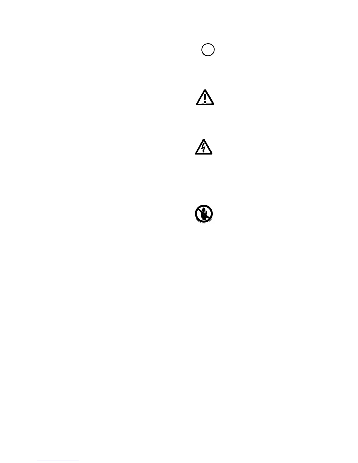
Safety Symbols
The following warning and informational symbols may be found in various
locations on the instrument. Only qualified personnel who recognize shock
hazards and are familiar with the safety precautions should use this instrument.
Read the manual carefully before operating this instrument.
Direct current
Courant continue
Gleichstrom
Corriente continua
Corrente continua
Alternating current
Courant alternatif
Dreiphasen-Wechselstrom
Corriente Atterna
Corrente alternata
Both direct and alternating current
Courant continu et courant alternatif
Allstrom (Gleich - und Wechselstrom
Corriente continua y corriente alterna
Corrente continua e corrente alternata
Earth ground terminal
Borne de terre
Erde (Bettriebserde)
Borne de Tierra
Terra (di funzionamento)
Protective conductor terminal
Borne de terre de protection
Schutzleiteranscluss
Borne de Tierra de Protección
Terra di protezione
On (Supply)
Marche (alimentation)
Ein (Verbindung mit dem Netz)
Connectado
Chiuso
Bio-Tek FL600 vii
Page 9
Off (Supply)
Arrest (alimentation)
Aus (Trennung vom Netz)
Desconectado
Aperto (sconnessione dalla rete di alimentazione)
Caution (Refer to accompanying documents)
Attention (voir documents d'accompanement)
Achtung siehe Begleitpapiere
Atención (vease los documentos incluidos)
Attenzione, consultare la doc annessa
Caution, risk of electric shock
Attention, risque de choc electrique
Gefährliche elektrische Spannung
Atención, riesgo de sacudida eléctrica
Alta tensione (in questo documento
Alta tensione non significa "te nsione pericolosa"
come definito in IEC 417)
Stay clear
Ne pas toucher svp .
Bitte nicht berühren
No tocario por favor
Si prega di non toccare
viii Bio-Tek FL600
Page 10

Contents
1. Introducing the Bio-Tek FL600
Hardware Requirements 1-3
Software Requirements 1-4
2. Getting Started
Setting Up the FL600 Reader 2-1
Installing KC4™ and FL600 Diagnostic Software 2-2
Installing KC4 2-2
Installing the Hardware Key 2-2
Installing the FL600 Diagnostic Software (Diagnostics Use)2-2
Checking the FL600 System 2-4
Using the FL600 Diagnostic Software 2-4
Filter Wavelength Locations 2-5
Checking the COM Port 2-5
Running System Diagnostics 2-7
What to Do if the Tests Fail 2-8
Exiting the FL600 Diagnostic Software 2-9
3. Replacing Filters and Adjusting Probe Height
Adding and Replacing Filters 3-1
Changing the Filters Inside the Reader 3-2
Setting the Filter Positions in KC4 Software 3-6
Utilizing the Filter Adapter System 3-7
Removing the Filter from the Adapter 3-7
Inserting the Replacement Filter into the Adapter 3-8
Adjusting Top Optical Probe Height 3-8
FL600 Interior Configuration Diagrams 3-10
4. Bio-Tek FL600 Maintenance
Maintaining the Reader 4-1
How to Maintain the Exterior 4-1
How to Replace the Air Filter 4-1
How to Replace the Lamp 4-3
Bio-Tek FL600 ix
Page 11

5. Technical Information
Bio-Tek FL600 Fluorescence/Absorbance Plate Reader 5-1
Physical Dimensions 5-1
Operating Conditions 5-1
Electrical Specifications 5-2
Optical Specifications 5-2
Scanning Mechanism 5-3
Temperature Control 5-4
Performance Specifications 5-4
CE Mark Approval 5-8
Computer Specifications for FL600 Diagnostic Software 5-10
FL600 Serial Communications 5-11
Ordering Filters 5-12
Fluorescence Filters 5-12
Absorbance Filters 5-14
x Bio-Tek FL600
Page 12

&KDSWHU
,QWURGXFWLRQ WR WKH
This chapter introduces the Bio-Tek FL600 Fluorescence
Plate Reader. You'll find information on hardware and
,QWURGXFLQJ7KH)/
Thank you for selecting the Bio-Tek FL600. The FL600 is a powerful
fluorescence and absorbance measurement system which measures
through the use of a photomultiplier tube housed inside of a light-
impermeable detection compartment. The FL600 is capable of quantifying
both soluble and cell-associated fluorescence. The system consists of:
%LR7HN
software requirements and optional equipment
)/
suggestions.
• Accessories Kit
Both software packages are for Windows-based PCs and provides the user
with full command of the operation of the X-Y scanner. FL600’s precision
X-Y mechanism scans a microplate with a sensitive optical detection
system to quantify the fluorescence or absorbance in each well.
• The Bio-Tek FL600 Fluorescence Plate Reader
• KC4™ reader control and data reduction software
• FL600 System Software for diagnostics
• Serial Communications Cable (P/N 75034)
Page 13

Virtually any microplate type from 6 to 384 wells can be used with the
FL600. Users can select any microplate from the FL600’s built-in list of
industry-standard plates, or they can define their own unique plate
format(s).
The FL600 is designed to meet international radio frequency emission
standards, EMC immunity standards, and user safety standards.
The Bio-Tek FL600 should be installed in a well-ventilated area, free from
dust and fumes. Keep the system away from direct sunlight and local heat
sources.
1-2
Introduction to the Bio-Tek FL600
Page 14

+DUGZDUH5HTXLUHPHQWV
0LQLPXP&RPSXWHU5HTXLUHPHQWVIRU)/6\VWHP6RIWZDUH
DQG.&6RIWZDUHIRU:LQGRZVDQG
• IBM™ 486 PC or clone 33 MHz clock
• 640 KB base memory, extended to 8 MB
• Color graphics monitor (VGA)
• Color graphics adapter (VGA)
• 120 MB hard drive
• High-density floppy disk drive 3½"
• 1 serial (COM) and 1 parallel (LPT) port
• Mouse and keyboard ports
• Microsoft or compatible mouse
5HFRPPHQGHG&RPSXWHU5HTXLUHPHQWVIRU)/6\VWHP
6RIWZDUHDQG.&6RIWZDUHIRU:LQGRZVDQG
• IBM 486 PC or clone 100 MHz clock
• 640 KB base memory, extended to 8 MB
• Color graphics monitor (VGA)
• Color graphics adapter (VGA)
• 120 MB hard drive
• High-density floppy disk drive 3½"
• 1 serial (COM) and 1 parallel (LPT) port
• Mouse and keyboard ports
• Microsoft or compatible mouse
• Surge/spike protector
Introduction to the Bio-Tek FL600
1-3
Page 15

5HFRPPHQGHG&RPSXWHU5HTXLUHPHQWV)RU:LQGRZV
• IBM 486 / 100 MHz PC or better compatible
• Memory: 640 KB base, extended to 16 MB minimum
• 250 MB hard drive
3ULQWHU
• Microsoft Windows compatible printer
6RIWZDUH5HTXLUHPHQWV
• FL600 System Software, version 2 or higher
• KC4™ reader control and data reduction software
• MS-DOS version 5.0 or later
• Microsoft Windows version 3.1 or later, or Microsoft
Windows 95 (with 16 MB memory)
1-4
Introduction to the Bio-Tek FL600
Page 16
&KDSWHU
*HWWLQJ6WDUWHG
This chapter discusses how to set up the Bio-Tek FL600
hardware, check the communication port and run the
diagnostic tests, install and configure the FL600 software,
6HWWLQJ8S7KH)/5HDGHU
and exit the FL600 system software.
CAUTION: It is recommended that two people lift the FL600, which weighs about 23
kg (50.6 lb.). Care must be taken when moving the device or removing it from the
packaging. Hold the device firmly from the bottom of the case when lifting it.
Setting up the Bio-Tek FL600 Fluorescence Plate Reader is simply a matter of
connecting the system to the computer via the computer’s serial port, installing
the software, and setting up communications parameters. One of the serial ports
most likely already has a mouse connected to it (the FL600 software, since it
operates under Windows, requires a mouse).
Step 1:
Step 2:
Step 3:
Step 4:
Step 5:
110V for 100-120V˜ operation,
220V for 200-240V˜ operation
Set the incubator power switch to the appropriate voltage as
follows:
Turn off the PC.
To connect the FL600, first attach the 9-pin D-type cable into the
computer’s serial port (COM1, COM2, COM3, or COM4).
Plug the other end of the cable into the Serial Data Port located at
the rear of the FL600 Fluorescence Plate Reader.
Connect the power cable to the back of the Plate Reader.
Step 6:
Plug all power cords into grounded, electrical outlets (use of a surge
protector is strongly recommended).
Page 17

The FL600 and all computer hardware must be electrically grounded and
connected to a viable surge protector to avoid dangerous shocks and to
avoid destroying the electronic components through electrical spikes and
surges.
,QVWDOOLQJ.&DQG)/'LDJQRVWLF6RIWZDUH
The FL600 is supplied with two Windows™ software packages, KC4™
and FL600 Diagnostic Software.
KC4 controls the reader, reduces the fluorescence and absorbance data,
and furnishes the reports.
The FL600 Diagnostic software provides diagnostics to test the reader.
Although it contains other functions, these are undocumented and
unsupported.
,QVWDOOLQJ.&
Please consult your KC4™ User’s Guide. Place disk 1 into the floppy
drive. Run Setup.exe by choosing the Run option from the File Menu of
your Windows program. This routine will guide you through the
installation of KC4 onto your hard disk.
,QVWDOOLQJWKH+DUGZDUH.H\
To use KC4 to control the reader and print data, the hardware key needs to
be installed on the parallel port of your computer. Please consult your
KC4 Operations manual for further instruction.
,QVWDOOLQJWKH)/'LDJQRVWLF6RIWZDUH
'LDJQRVWLFV8VH
To install the FL600 software, follow these steps:
Step 1:
Step 2:
Step 3:
Step 4:
Turn on your computer, start Windows, and activate Windows’
Program Manager, if necessary.
Insert the FL600 Setup diskette into the floppy drive.
Select
Run
from the Windows’
File
menu.
Type drive: setup, (i.e., b: setup).
2-2
Getting Started
Page 18

Setup will indicate to you that all FL600 diagnostic software files will be
installed into the drive and directory C:\FL600. You will be given the
opportunity to change either the drive or the directory (or both). Setup
creates a new group called Bio-Tek FL600. Note that this is different from
the KC4™ group created by the KC4™ software.
NOTE: Be sure that TrueType Fonts are enabled in the Fonts Section of the
Windows Control Panel. FL600 requires certain TrueType fonts when
printing reports. For more information on activating TrueType Fonts,
please check your Windows User’s Guide.
Getting Started
2-3
Page 19

&KHFNLQJWKH)/6\VWHP
Before you begin to use the FL600 software, you should first check that
the FL600 settings are correct.
8VLQJWKH)/'LDJQRVWLF 6RIWZDUH
Step 1:
To start the FL600 diagnostic software:
From within Windows, double-click on the FL600 icon.
Depending on your computer speed, the FL600 diagnostic
software should boot up from within 15 to 60 seconds.
Longer than that might indicate that your computer system
needs more RAM or clock speed.
The FL600 Plate Layout screen will appear:
2-4
Figure 2-1: FL600 Plate Layout Screen
Getting Started
Page 20

)LOWHU:DYHOHQJWK/RFDWLRQV
Refer to Chapter 3 for instructions on determining filter locations. Record
the filter locations to be entered into KC4.
&KHFNLQJWKH&203RUW
Next, turn on the FL600 Reader using the switch located on the right side
of the front panel and check the COM Port Setting.
NOTE: When the Reader has been switched on, a green light next the switch
lights up and the plate transport moves out, ready to load a plate.
Step 1:
Pull down the
Instrument
menu and select
Communications
. A
dialog box appears showing you the currently selected
communications port, through which the software is attempting to
communicate with the FL600 Reader:
Figure 2-3: Communications Port Settings Screen
Getting Started
2-5
Page 21

Step 2:
Check to ensure that the correct com port is selected.
You can test the COM port to see if it is connected and
communicating correctly by clicking on
Test.
If the FL600
is switched on and connected correctly, you will see the
following dialog box appear:
Figure 2-4: Plate Model Information Window
NOTE: You will see an error message if any of the following conditions exist: the
FL600 is not correctly connected; it is not switched on; the incorrect
communications port is selected; there is a cable problem. Check that
the reader is switched on and correctly connected to the computer, that
you have selected the correct communications port, and that the cable is
operational. Then close the message window and try the
Click on OK to close the dialog box. You will return to the
test
again.
communications port information dialog box.
Click on OK to save the selected communications port, if
you’ve changed it.
NOTE: If you select
Cancel
, the communications window will close without
recording any changes.
2-6
Getting Started
Page 22

5XQQLQJ6\VWHP'LDJQRVWLFV
The FL600 diagnostic software will automatically test the functionality of
the Plate Reader, using the diagnostic tests.
Step 1:
Step 2:
Pull down the
Instrument
menu and select
Diagnostics
. You will
see the following window.
Figure 2-5: Initial FL600 Diagnostics Screen
To start diagnostic tests, click on the
Start
button. Information
detailing the status of the reader appears in the window as each test
is completed. (To close the window without starting the diagnostic
tests, click on
Close or Cancel
.)
Getting Started
2-7
Page 23

Once the FL600 has completed its self-diagnostic tests,
your screen should look similar to the one that follows:
Figure 2-6: FL600 Diagnostics Screen After Testing
:KDW7R'R,IWKH7HVWV)DLO
If any of the diagnostic tests should fail, click on the
below
the computer and the reader was will display on the screen.
Cancel
. A log showing exactly what the communications between
Print the log by selecting the
Enter the requested details on the fax cover sheet (which
prints automatically with the log) and fax both sheets to
Bio-Tek’s Technical Assistance Center at (802) 655-3399
in the USA or +32-3-825-47-49 in Europe. Technical
Assistance personnel will review the problem and instruct
you on what to do next.
To close the log, select the
Then, to close the diagnostics window and return to the
main screen, click on the
window.
File
menu and choosing
File
menu and choose
Cancel
button on the Diagnostics
Log...
button just
Close
Print
.
.
2-8
Getting Started
Page 24

([LWLQJ7KH)/'LDJQRVWLF6RIWZDUH
Step 1:
Step 2:
Select
unsaved work. Click on
exit without saving changes, or
You will be prompted as to whether or not you want to close the
Exit
from the File menu. You will be prompted to save any
Yes
to save the changes and exit, No to
Cancel
to forget all about exiting.
reader door, thus parking the plate transport inside the reader.
Figure 3-11: The Exit Window
To exit the software and have the door automatically closed, click in the
Close reader door
close the door (make sure you have removed your plate). Click
check box and click on OK to exit the software and
Cancel
continue without exiting.
to
NOTE: You should always opt to close the reader door when you are shutting
down the system to protect the optics from dust. Alternatively, the
carrier can be withdrawn and the reader door closed by pressing the
button located in the recess under the plate carrier.
NOTE: You can remove this software from your system (save the diskettes)
and reload it if you suspect that you are having any problems with the
instrument.
Getting Started
2-9
Page 25

2-10
Getting Started
Page 26

&KDSWHU
5HSODFLQJ)LOWHUVDQG
$GMXVWLQJ3UREH+HLJKW
This chapter discusses how to add and replace filters and
$GGLQJDQG5HSODFLQJ)LOWHUV
adjust probe height for the FL600.
Adding new filters or replacing existing filter sets is a two-step process:
• Changing the excitation and emission or absorption filters in
the filter wheels inside the reader.
• Changing the settings to reflect the filter change in the KC4™.
The settings in the system software must correspond exactly to the
physical location and specification of the filters on the filter wheels. An
error in the system software specification for the filter could damage the
instrument and affect the FL600 warranty.
Page 27

&KDQJLQJ)LOWHUV ,QVLGHWKH5HDGHU
Step 1:
Ensure that the plate carrier is parked inside the reader.
Press the red button located in a recess under the plate
carrier so that the plate carrier moves inside the reader and
stops.
Park Button
Figure 3-1: Parking the Plate Transport Mechanism
(Plate Carrier)
Step 2:
Step 3:
Power down the FL600, and disconnect the reader’s power cord.
Never operate the instrument with the cover off. Operating the reader
without a cover poses a serious shock hazard and may damage the
detection circuit.
Exposing the inside measurement chamber to ambient light for more
than 30 minutes may cause saturation of the measurement device.
Should this occur, please wait 24 hours before reading.
Remove the reader’s cover.
Using a 4 mm Allen wrench (supplied in the Accessories
Kit), remove the five screws (Figure 3-2) that secure the
reader’s cover to the base.
Remove the top cover and set it aside.
3-2
Bio-Tek FL600
Page 28

Figure 3-2: Removing the cover screws
Step 4:
Remove the covers on both filter wheels.
Excitation Filter
Wheel Cover
Locate the two filter assemblies at the rear of the reader,
adjacent to the printed circuit board (Figure 3-3).
Emission Filter
Wheel Cover
Bio-Tek FL600
Figure 3-3: Filter wheel locations
Remove the filter wheel covers by pulling up on the heads
of the plastic snap catches. (Figure 3-4)
3-3
Page 29

Figure 3-4: Removing the cover on the emission filter wheel
Step 5:
Step 6:
Step 7:
Remove the filters you wish to change, being careful not to touch
the filter’s glass surface, or other optical components. Use extreme
care to avoid dropping the filter into the interior of the instrument.
Rotate the filter wheel until you reach the filter you want to
change.
Using filter forceps (available in the Accessory Kit),
remove the filter cell by pulling it straight up and out of the
wheel.
If removing absorbance filters, remove the holder
containing the filter, not the filter itself.
Ensure that the glass surfaces of the filters are free of dust and
smudges.
Insert the new filter, and note its wavelength and position on the
filter wheel.
Fluorescence Filters:
3-4
Align the new filter with the filter wheel, using the
illustration below (Figure 3-5). The arrow on the filter cell
should point away from the center of the filter wheel.
Insert the new fluorescence filter, and seat the filter by
applying gentle, equal pressure on the edges of the filter
housing.
Helpful hint: If the filter is marked 485/20X:
• 485 is the center wavelength;
• 20 is the bandwidth at one-half maximum transmission
(BWHM) of the excitation (X) filter.
Bio-Tek FL600
Page 30

An emission filter has an “M” designation.
y
• A dual-function Excitation/Emission filter has an
“X/M“ designation.
Absorbance Filters:
Insert the filter into the filter holder, and insert this
assembly into the filter wheel.
Absorbance filters do not need to be aligned.
Step 8: Note the filter’s position on the wheel (the molded letters A, B, C
are to the right of each filter), and the wavelength that is printed on
the top or side of each filter cell.
1
1\Y
\YW^
W^]U
]U^
^d
d
1
1b
bb_g
b_g
Figure 3-5: Aligning the filter with the filter wheel
Step 9: Replace the covers on the filter wheels. Put any unused filters in a
secure place.
Secure the filter wheel covers by gently placing the cover
over the access hole and then pressing down on the plastic
snap covers.
Fit the instrument cover, and secure it using the five screws.
Seal the unused filters in a plastic container, and store them
in a cool, dry location.
Step 10: Re-connect the power cable, and power up the reader.
The plate carrier will move to the plate load position.
Bio-Tek FL600
3-5
Page 31

6HWWLQJWKH)LO WHU3RVLWLRQVLQ.&6RIWZDUH
The second and most important step in changing or adding filters to the
reader is changing the KC4 software filter settings to accurately reflect the
new filters and their position on the wheel. The values for filters in the
KC4 software must match the values of the filters in the reader to avoid
damaging the reader and invalidating data.
NOTE 1: Settings are stored on the PC, not the FL600. Remember to reprogram
the filter settings if you move the unit to another PC.
3-6
Bio-Tek FL600
Page 32

8WLOL]LQJWKH)LOWHU$GDSWHU6\VWHP
The FL600 comes equipped with a set of “500 series” fluorescence filters,
which fit directly into the filter wheel. Should your application require
absorbance filters of different wavelengths than those originally supplied
with your instrument, you may order them from Bio-Tek.
Absorbance wavelengths are available only in the smaller “287 series.”
These filters must be fitted into a filter adapter before insertion into the
filter wheel. The following instructions explain how to change the filter in
the adapter.
The “287 series” filter system involves the filter, the filter adapter, a
retaining ring, and a removal-insertion tool. The tool is a cylindrical object
about two inches tall, with nodes protruding from the top and bottom.
5HPRYLQJWKH)LOWHUI URPWKH$GDSWHU
Step 1:
Step 2:
Step 3:
Step 4:
Step 5:
Step 6:
Step 7:
Step 8:
Remove the filter adapter from the filter wheel, as described in the
section entitled Changing Filters Inside the Reader.
Place the adapter on a clean table. Be careful not to work too close
to the edge of the table, and give yourself plenty of space. (The
filter is very small and easy to misplace when it pops out.)
Place the adapter with the wide end face-down against the table.
Insert the longer node of the tool into the top of the adapter.
Place your thumbs on top of the tool and your other fingers along
the edges underneath the adapter.
Lift both objects as a unit, to approximately one inch off the table.
Make sure that you keep the adapter parallel to the table.
Firmly press the tool down into the adapter, until the filter and
retaining ring pop out onto the table.
Put the filter in a safe, clean place for future use.
Bio-Tek FL600
3-7
Page 33

,QVHUWLQJWKH5HSODFHPHQW)L OWHULQWRWKH$GDSWHU
Step 1:
Ensure that the replacement filter is free of dust and smudges. If
not, carefully clean the filter with a cotton swab soaked in alcohol.
Step 2:
Center the replacement filter on top of the retaining ring, and then
place the adapter onto the filter, wide end down. If possible, align
the window on the side of the adapter with the last four digits of
the filter number, so that the four digits will appear in the window.
Step 3:
Place both thumbs on either side of the top edge of the adapter, and
press down very firmly with equal pressure, until the assembly
snaps together.
Step 4:
Insert the shorter node of the tool into the adapter, and press down
firmly to seat the filter.
Step 5:
Install the filter adapter into the filter wheel, as described in the
section entitled Changing Filters Inside the Reader.
$GMXVWLQJ7RS2SWLFDO3UREH+HLJKW
Each FL600 model has been factory-configured with a top probe height
that will provide maximum sensitivity for the specified plate thickness.
Should you wish to change plate types, it may be necessary to reset the
probe height to prevent the probe from hitting the plate, or to maximize
sensitivity.
To achieve maximal sensitivity when using the top optical probe it is
necessary to adjust the probe height as low as possible, while still allowing
free movement of the microplate underneath. Follow the directions below
to adjust the top probe height, referring to the diagrams in Figure 3-6.
Step 1:
To withdraw the plate carrier into the instrument, press the plate
carrier retrieval button located on the front underside of the
instrument. Shut off the instrument, and unplug the power cord.
Step 2:
Using the 4 mm hex screw driver provided in the accessories box,
remove the five machine screws holding down the top cover.
These screws are located in the recessed pockets on the underside
edge of the bottom shroud. (See Figure 3-2.)
NOTE 1: Never operate the instrument with the cover off. Operating
the reader without a cover poses a serious shock hazard and may
damage the detection circuit.
3-8
Bio-Tek FL600
Page 34

NOTE 2: Exposing the inside measurement chamber to ambient light
for more than 30 minutes may cause saturation of the measurement
device. Should this occur, please wait 24 hours before reading.
Step 3:
Step 4:
Step 5:
Step 6:
Step 7:
Step 8:
Reaching into the inside of the instrument, place a microplate on
the plate carrier, ensuring that it is the same type you usually use.
Place the probe height adjustment shim (provided in the
accessories box) on the top of the plate, taking care to center it over
the plate. The end that contains the notch matching the top probe
size must be oriented toward the optical probe.
Using the 2.5 mm hex wrench provided, loosen the two set screws
holding the top probe in place. These two set screws are located on
the front surface of the top probe.
Carefully raise the probe so that the bottom of the top probe is
above the top edge of the plate and shim on the plate carrier.
Turn the X-axis and the Y-axis drive screws so that the appropriate
notch in the shim is located underneath the top probe.
Carefully lower the top probe into the notch of the shim, taking
care not to damage the probe. Make sure that the probe is straight
and vertical, and then tighten the set screws.
Step 9:
Step 10:
Step 11:
Step 12:
Step 13:
Turn the X-axis drive screw so that the plate is no longer located
under the probe. Make sure that the plate carrier has not traveled
so far as to open the door. If it has done so, back the plate up by
turning the X-axis screw.
Remove the microplate and shim from the plate carrier.
Replace the top cover. Carefully align the five 4 mm screws
holding the top shroud in place, and then tighten them.
Check the door for ease of movement. If the door movement is
impeded, try readjusting top shroud, making sure that it is on
properly and that the screws are tightened sufficiently.
Attach the power cord, and turn on the power switch. The plate
carrier should eject.
Bio-Tek FL600
3-9
Page 35

FL 600 IN TER IO R CO N FIG U R ATION
Y-AXIS SCREW
BOTTOM
PROBE
PROBE
MICROPLATE
TOP
INC U BATO R
EMISSION
FILTER
WHEEL
EXCITATION
FILTER
WHEEL
LAMP
PMT
POWER
SUPPLY
SET SCREW S
DOOR
X-AXIS SCREW
TOP PR O BE A DJU STMEN T JIG
(top view )
5 mm probe
1-3 m m probe
Figure 3-6: FL600 interior configuration
FA N
FL600 TO P PRO BE POSITION
(side v iew )
SET SCRE W
TOP PRO BE
PROBE HEIGHT ADJUSTMENT JIG
0,&523/$7(
3-10
Bio-Tek FL600
Page 36

&KDSWHU
%LR7HN)/0DLQWHQDQFH
0DLQWDLQLQJ7KH5HDGHU
The FL600 requires regular, systematic maintenance to guarantee that it
will run in top form. This includes regularly cleaning the reader’s exterior,
changing its air filter, and replacing its lamp.
This chapter explains the preventative maintenance
procedures for the FL600, including how to
replace the air filter and the lamp.
+RZWR&OHDQWKH([WHULRU
Exterior maintenance consists of simply wiping the reader with a damp
cloth and mild detergent.
+RZWR&OHDQDQG 5HSODFHWKH$L U)LOWHU
Dust can affect flourescence values. The FL600 air filter should be
cleaned or replaced once every six months, more often if your site is
especially dusty.
Step 1: To access the air filter, snap the fan cover away from the right hand
underside of the reader (on the same side as the plate transport), by
grabbing it between your thumb and forefinger and pulling
downward. (See
Figure 4-1
Figure 4-2
and
.)
Page 37

DLU ILOWHU
U
Figure 4-1
Step 2: Remove the air filter, a thin, grey piece of material.
DLU ILOWH
IDQ FRYHU
Step 3:
Clean the filter by blowing the dust out with an air blower, and/or
rinsing by hand with sudsy water and then clean water. Be sure to
dry the filter thoroughly before reinserting it into the fan cover.
Step 4:
If the filter is damaged or difficult to clean, or if the fan cover is
damaged, replace the entire fan cover and filter with Bio-Tek P/N
49840.
Step 5:
Return the fan cover to its original position at the underside of the
reader, and snap it back into place.
4-2
Figure 4-2
Bio-Tek FL600
Page 38

Never use the FL600 without an air filter.
+RZWR5HSODFHWKH/DPS
NOTE: Full instructions for lamp replacement are provided with the lamp
replacement kit.
CAUTION! Never touch the surface of the lamp, as any residue could
hamper illumination. We recommend that you wear gloves when
touching a new lamp.
Step 1:
Step 2:
Make sure the plate transport mechanism is “parked.” To do so,
press the red button in the recess under the plate carrier, so that the
plate carrier moves inside the reader and stops.
park button
Shut off the FL600, and then unplug both the power and computer
Figure 4-3
cables from the rear of the device.
Bio-Tek FL600
4-3
Page 39

CAUTION! It is very dangerous to operate the FL600 with the cover
off, as there is a probability of electrical shock.
Step 3:
Step 4:
Using the 4 mm Allen wrench provided in the accessories kit,
unscrew the five screws holding the reader cover to the base.
Remove the top cover, and set it aside.
Figure 4-4
Step 5:
Step 6:
At the back of the FL600, on the left side, you will find the
lamp assembly (as shown below).
Excitation Filter Wheel
Lamp
Assembly
Remove the two PMT wires from the cable harnesses on the lamp
Emission Filter Wheel
Figure 4-5
cover, and disconnect the solenoid cable. (See Figure 4-6.)
Unscrew the two thumb screws that hold the lamp cover onto the
lamp assembly, and lift up the lamp cover. (See Figure 4-7.)
4-4
Bio-Tek FL600
Page 40

Step 7:
Using the 3mm Allen wrench provided in the accessories kit,
unscrew the three screws mounting the lamp assembly to the lamp
housing.
CAUTION! Fingerprints can ruin the FL600 quartz halogen
lamp and render it unusable.
Step 8:
Disconnect the lamp wires, and slide the lamp assembly away from
the PMT base and toward the fan.
VROHQRLG
FDEOH
FDEOH KDUQHVV
ZLUHV
307 EDVH
Step 9:
Step 10:
Step 11:
Step 12:
Step 13:
Step 14:
FDEOH KDUQHVV
Carefully remove the lamp assembly from the lamp housing.
Remove the lamp from the lamp assembly by removing the three
Figure 4-6
3mm hex screws.
Insert the new lamp (P/N 6000556S) into the lamp assembly, and
then replace the three screws.
Remount the lamp assembly to the lamp housing, and screw down
the three 3mm hex screws. Be careful not to over-tighten them.
Reconnect the two lamp wires in any configuration. Polarity is not
an issue.
Replace the lamp cover, making sure that cable attached to the
solenoid is routed through the center hole of the lamp cover.
Bio-Tek FL600
4-5
Page 41

Step 15:
Attach the lamp cover to the lamp assembly, using the two thumb
screws. Be careful not to over-tighten them.
Step 16:
Step 17:
Step 18:
Step 19:
ODPS FRYHU
Reconnect the solenoid cable, and re-route the cables through the
cable harness.
Replace the reader cover, and attach it by screwing in the five
screws.
Plug in the power cable and the computer cable.
Turn on the FL600. The plate transport mechanism will
automatically move into the load position.
WKXPE VFUHZV
ODPS 31 6
IDQ
ODPS DVVHPEO\
ODPS ZLUHV
ODPS KRXVLQJ
Figure 4-7
4-6
Bio-Tek FL600
Page 42

&KDSWHU
7HFKQLFDO,QIRUPDWLRQ
This chapter contains a variety of technical information, including
hardware specifications for the Bio-Tek FL600 Fluorescence Plate
Reader.
%LR7HN)/)OXRUHVFHQFH$EVRUEDQFH3ODWH
5HDGHU
3K\VLFDO'L PHQVLRQV
Height 247 mm (97 in.)
Width 707 mm (278 in.)
Depth 426 mm (168 in.)
Weight 23 kg (50.6 lb.)
Shipping Weight 30 kg (66 lb.)
2SHUDWLQJ&RQGLWLRQV
Temperature +4°C to +35°C
Relative Humidity 20% to 80%, non-condensing
Page 43

(OHFWULFDO6SHFLIL FDWLRQV
Fuse 5.0 amp, time-delay T, glass, 5 mm x 20 mm, 250 volt-type
(Part Number 46055)
Input Voltage 90-132 volts AC
180-240 volts AC
47-63 Hz, 525 VA max
The power supply has a auto ranging power input.
Internal Voltages ±15 volt DC, +24 volt DC, +5 volt DC,
-950 volt DC
2SWLFDO6SHFLILFDWL RQV
Lamp Type M32-Type, Tungsten-Halogen, 75 watt
optically stabilized lamp in fan-cooled assembly
Lamp Life 2000 hours minimum
Excitation Range 300 nm - 650 nm filters
fitted in a motor driven wheel assembly
Emission Range 350 nm - 750 nm filters
fitted in a motor driven wheel assembly (complete
with photomultiplier)
Absorbance Range 340 nm - 750 nm filters
Filter Wheel 6 positions
Detector Photomultiplier Tube
Probe Diameter The fully randomized Quartz fiber bundles are
available in four sizes to meet user needs. Different
probes can be fitted to the upper and lower positions
at the factory.
5.0 mm general purpose probe for all media up to
96 wells.
3.0 mm general-purpose probe suitable for media up
to 96 wells
5-2
Technical Information
Page 44

1.5 mm special probe for 384-well plates with
minimum crosstalk, reduced sensitivity on other
plates
1.0 mm special probe for high-density media.
Probe Selector Probe diameters can be different in the top read and
bottom read positions.
Selection of top or bottom read position is under software
control.
The height of the top reading probe may need to be set by
the user for different plate heights. See the section
entitled Adjusting Top Optical Probe Height in Chapter
3.
6FDQQLQJ0HFKDQLVP
Speed 65 mm/second maximum
Resolution 5 microns
Repeatability within ±25 microns
X Drive 10.0 mm leadscrew
Y Drives 10.0 mm leadscrew
There are two (Y axis) Probe scanning mechanisms fitted for top and bottom
read configurations
Probe Configurations Selection of top or bottom reader or optical density mode
under computer control
Technical Information
5-3
Page 45

7HPSHUDWXUH&RQWURO
The FL600 is fitted with a heater block which can be programmed to heat the
plate to a temperature above ambient.
Temperature Range Ambient +6° Celsius to 50° Celsius
Uniformity Within ±0.5° Celsius across a 96 well Dynatech black plate
measured with thermal probes in the center and four corner
wells and 150 µl of Johnsons Baby Oil per well.
Time to Stabilize Within 30 minutes after switching on
Time to Cool Approx. 2.5 hours from 37° Celsius to 6° Celsius
above the on-board ambient temperature reference
sensor.
3HUIRUPDQFH6SHFLILFDWLRQV
Standard Plate Types All 96-well microplates and most 48- to 6-well
tissue culture plates
High-Density Plate Types 384-well microplates.
Note: Reader performance will be optimized by factory-
fitting of a smaller fibre optic probe 1.0mm or 1.5mm
diameter).
60, 72 and 96 well Terasaki plates
Note: Optimum probe size is 1.0mm or 1.5mm diameter.
A custom plate adapter is required.
Plate Sizes Minimum 126 mm × 84 mm
Maximum 133 mm × 90 mm
5-4
Technical Information
Page 46

Sensitivity (Specified)
Bottom Reading 5.0mm Probe
Top Reading 5.0mm Probe
10 pg/ml solution of Sodium Fluoroscein, in PBS,
150 µl per well Signal to Noise Ratio of 2 or greater.
Excitation 485/20, Emission 530/25
Hellma 96-well quartz plate.
125 ng/ml solution of Propidium Iodide, in PBS,
150 µl per well Signal to Noise Ratio of 2 or greater.
Excitation 485/20, Emission 645/40
Cestar 3603 96-well plate.
20 pg/ml solution of Sodium Fluoroscein, in PBS,
300 µl per well Signal to Noise Ratio of 2 or greater.
Sensitivity (Typical)
Excitation 485/20, Emission 530/25
Dynatech 96-well black plate.
160 pg/ml solution of Methylumbelliferone, in CBB,
300 µl per well Signal to Noise Ratio of 2 or greater.
Excitation 360/40, Emission 460/40
Dynatech 96-well black plate.
125 ng/ml solution of Propidium Iodide, in PBS,
300 µl per well Signal to Noise Ratio of 2 or greater.
Excitation 485/20, Emission 645/40
Dynatech 96-well black plate.
Typical sensitivities can be two to three times
more sensitive than specified
Technical Information
5-5
Page 47

Data Capture
Up to 6 different filter sets and sensitivities per
scan; maximum of 300 scans (1800 repeat reads
of the plate); wait time of up to 9999 seconds
between each read of a plate
Kinetic Speed
End Point Speed
Static Mode
30 seconds/plate, using Rapid Mode
4-6 seconds/column (depending on computer
speed), using Rapid Mode
5-10 reads/second/filter set, using Fast Kinetic
mode
1 read/3 seconds/2 filter sets, using Fast Kinetic
mode
48 seconds/plate including in and out time using
rapid mode, in fluorescence.
The probe will remain stationary under a well 0.1,
0.35, 0.5, or 2 seconds before taking a reading. A
single sample can be taken or 2, 3, 4, 5, 10, 20, 50,
or 100 readings that are averaged. Time between
samples can range from 10 ms to 2550 ms.
Plate Shaker
5-6
Technical Information
The plate may be shaken at three settings for a
period of 1 to 255 seconds. The settings are:
High 25 Hz 0.6 mm travel
Medium 17 Hz 0.9 mm travel
Low 12.5 Hz 1.2 mm travel
Page 48

Fixed References
The instrument contains 4 embedded references
which are optionally read at the start of each scan.
The references are:
1. Black Acetal Reference Disk used for Optical
Density 0% transmission and fluorescence
background
2. Green Reference Disk for fluorescence with
Excitation 485 and Emission 530nm.
3. Brown Reference Disk for fluorescence with
Excitation 590 and Emission 645nm.
4. Clear Optical path used for Optical Density
100% transmission
Technical Information
5-7
Page 49

%DVHG RQ WKH WHVWLQJ EHORZ WKH GHYLFH EHDUV WKH &( PDUN
(OHFWURPDJQHWLF,QWHUIHUHQFHDQG6XVFHSWLELOLW\
EC EMC DIRECTIVE 89/336/EEC
EN 50081-1, CLASS A-EMISSIONS
The device has been type tested by an independent testing laboratory and found
to meet the requirements of EC Directive 89/336/EEC for Radiated Emissions
and Line Conducted Emissions. Verification was to the limits and methods of
EN 55022:1995. The device is classified as EN 55022, Class A.
EN 50082-1 IMMUNITY
The device was also tested and found to meet requirements for Electrostatic
Discharge Susceptibility, Radiated Susceptibility, and Electrical Fast
Transient/Burst Susceptibility. Verification of compliance was conducted to
the limits and methods of EN 50082-1:1992, IEC 1000-4-2:1995, EN 61000-43:1996, and IEC 1000-4-4:1995.
USA FCC CLASS A
Warning: Changes or modifications to this unit not expressly approved by the
manufacturer could void the user's authority to operate the equipment.
This equipment has been tested and found to comply with the limits for a Class
A digital device, pursuant to Part 15 of the FCC Rules.
These limits are designed to provide reasonable protection against harmful
interference when the equipment is operated in a commercial environment.
Like all similar equipment, this equipment generates, uses, and can radiate
radio frequency energy and, if not installed and used in accordance with the
instruction manual, may cause harmful interference to radio communications.
Operation of this equipment in a residential area could cause interference, in
which case the user will be required to correct the interference at his own
expense.
5-8
Technical Information
Page 50

CANADIAN DEPARTMENT OF COMMUNICATIONS CLASS A
6DIHW\
This digital apparatus does not exceed Class A limits for radio emissions from
digital apparatus set out in the Radio Interference Regulations of the Canadian
Department of Communications.
Le present appareil numerique n'met pas du bruits radioelectriques depassant
les limites applicables aux appareils numerique de la Class A prescrites dans le
Reglement sur le brouillage radioelectrique edicte par le ministere des
Communications du Canada.
This device has been type tested by an independent laboratory and found to
meet the requirements of:
EC DIRECTIVE 73/23/EEC, LOW-VOLTAGE DIRECTIVE
EN 61010-1: “Safety requirement for electrical equipment for measurement,
control and laboratory use. Part 1 General requirements.”
Technical Information
5-9
Page 51

&RPSXWHU6SHFLILFDWLRQV)RU)/'LDJQRVWLF6RIWZDUH
0LQLPXP&RPSXWHU 5HTXLUHPHQWV
)RU:LQGRZV DQG
Base Unit IBM 486 PC or clone 33 MHz clock
640 KB base memory, extended to 8 MB
Color graphics monitor (VGA)
Color graphics adapter (VGA)
120 MB hard drive
High-density floppy disk drive 3½"
1 serial and 1 parallel port
Microsoft Windows compatible mouse and keyboard ports
Printer Microsoft Windows compatible printer
5HFRPPHQGHG&RPSXWHU5HTXLUHPHQWV
)RU:LQGRZV DQG
Base Unit IBM 486 DX PC or clone 100 MHz clock or better
640 KB base memory, extended to 8 MB
Color graphics monitor (VGA)
Color graphics adapter (VGA)
120 MB hard drive
High-density floppy disk drive 3½"
1 serial and 1 parallel port
Microsoft Windows compatible mouse and keyboard ports
Surge/spike protector
Printer Microsoft Windows compatible printer
5HFRPPHQGHG&RPSXWHU5HTXLUHPHQWV
IRU:LQGRZV
Base Unit IBM 486 DX PC or clone 100 MHz clock or better
6RIWZDUH5HTXLUHPHQWV
Bio-Tek FL600 System software is compatible with Windows 95 (16 MB of RAM
is recommended)
5-10
Technical Information
640K base memory, extended to 16 MB minimum
250 MB hard drive
MSDOS version 5.0 or higher
Bio-Tek FL600 System software version 2
Bio-Tek KC4 reader control and data reduction software
Microsoft Windows version 3.1 or higher
Page 52

)/6HULDO&RPPXQLFDWLRQV
The reader communicates with the computer via a 9-pin D-type male-female
connector (P/N 75034).
The connector is wired as follows.
PIN Computer FL600
1 DCD Not used
2 RX TX data to computer
3 TX RX data from
4 DTR Not used
5 GND Signal ground
6 DSR Not used
computer
7 RTS Linked to pin 8
8 CTS Linked to pin 7
9 RI Not used
Serial Port
Parameter
KC4 Reader
Control and Data
Reduction
FL600
Diagnostic
Software
Software
Baud rate 9600 9600
Data bits 8 8
Parity Even None
Stop bit 1 1
Note: The FL600 Diagnostic Software settings can not be changed- through
either software or hardware tools.
Technical Information
5-11
Page 53

2UGHULQJ)LOWHUV
The following list reflects standard and custom filters for use with the FL600. For the
latest additions to this list, please contact Bio-Tek’s Customer Service Department.
)OXRUHVFHQFH)LOWHUV
These are high-quality interference filters fitted in 22 mm diameter cells.
NOTE: The positions of each filter in the excitation and emission wheels can be user-
configured for minimum switch time of pairs, in kinetics applications using twocolor fluorescence.
FL500 AND FL600 EXCITATION/EMISSION FILTERS
FL500 use
Wavelength/
Bandwidth
360/40 5002020 Excitation only Standard Filter
380/20 5002028 Excitation only
Part
Number
(std 420-
700+nm
versions)
Comments
400/30 5002005 Excitation only
420/50 5002006 Both
440/30 5002027 Both
440/40 5002007 Both
450/50 5002008 Both
460/40 5002022 Both Standard Filter.
485/20 5002021 Both Standard Filter
485/40 5002009 Both
508/20 5002018 Both
530/25 5002023 Both
tandard Filter, used in both wheels
545/40 5002010 Both
5-12
Technical Information
Page 54

Wavelength/
Part
FL500 use
Comments
Bandwidth
Number
(std 420-700+nm
versions)
560/15 5002015 Both Alamar Blue™ Excitation Filter
560/20 5002011 Both
560/40 5002012 Both
590/20 5002025 Both Standard Filter
590/35 5002024 Both Standard Filter
620/40 5002013 Both
630/32 5002014 Both
633/10 5002017 Both
635/10 5002019 Both
645/40 5002026 Both Standard Filter
680/30 5002029 Both
Excitation Filters
340/30 5002030 Excitation only
410/10 5002001 Excitation only 400/30 filter is preferred in most
cases
540/25 5002004 Excitation only
310/20 5002039 N/A
340/11 5002043 Excitation only
Technical Information
5-13
Page 55

$EVRUEDQFH)LOWHUV
All absorbance filters are placed in the emission filter wheel and require an adapter
(part #6002000). See the section entitled Utilizing the Filter Adapter System in
Chapter 3, for further information. For the latest additions, please contact BioTek’s Customer Service Department.
FL600 ABSORBANCE FILTERS
Wavelength Part Number (2874 plus
340 2874340
380 2874380
405 2874405
410 2874410
415 2874415
wavelength)
440 2874440
450 2874450
465 2874465
470 2874470
490 2874490
515 2874515
530 2874530
540 2874540
550 2874550
562 2874562
570 2874570
5-14
Technical Information
Page 56

Wavelength Part Number (2874 plus
Wavelength)
580 2874580
590 2874590
600 2874600
610 2874610
620 2874620
630 2874630
640 2874640
650 2874650
660 2874660
720 2874720
750 2874750
Technical Information
5-15
Page 57

5-16
Technical Information
 Loading...