

Page 1
Operator’s Manual
Absorbance Microplate Reader
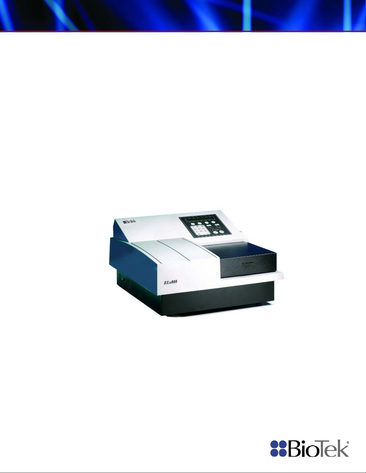
ELx808
™
Page 2

Page 3

ELx808™
Absorbance Microplate Reader, All Models
Operator’s Manual
April 2013
© 2013
Part Number 7341000
Revision P
BioTek® Instruments, Inc.
Page 4

ii | Preface
Notices
BioTek® Instruments, Inc.
Highland Park, P.O. Box 998
Winooski, Vermont 05404-0998 USA
All Rights Reserved
© 2013, BioTek® Instruments, Incorporated. No part of this publication may be
reproduced, transcribed, or transmitted in any form, or by any means electronic or
mechanical, including photocopying and recording, for any purpose other than the
purchaser’s use without written permission of BioTek Instruments, Inc.
Trademarks
BioTek® is a registered trademark, and ELx808™, 4-Zone™ and Gen5™ are trademarks
of BioTek Instruments, Inc. Microsoft
trademarks or trademarks of Microsoft Corporation in the United States and/or other
countries.
®
, Windows®, and Excel® are either registered
All other trademarks are the property of their respective holders.
Restrictions and Liabilities
Information in this document is subject to change and does not represent a
commitment by BioTek Instruments, Inc. Changes made to the information in this
document will be incorporated in new editions of the publication. No responsibility is
assumed by BioTek for the use or reliability of software or equipment that is not
supplied by BioTek or its affiliated dealers.
BioTek Instruments, Inc.
Page 5

Contents
Notices ........................................................................................... ii
All Rights Reserved ...................................................................... ii
Trademarks ................................................................................ ii
Restrictions and Liabilities ............................................................ ii
Contents ........................................................................................ iii
Contact Information ...................................................................... viii
Customer Service and Sales ....................................................... viii
Service/TAC ............................................................................ viii
European Coordination Center/Authorized European Representative viii
Revision History .............................................................................. ix
Document Conventions ................................................................... xii
Intended Use Statement ................................................................. xii
Quality Control .............................................................................. xii
Warranty & Product Registration ...................................................... xiii
Repackaging and Shipping .............................................................. xiii
Warnings ..................................................................................... xiii
Hazards ....................................................................................... xiv
Precautions ................................................................................... xv
CE Mark ....................................................................................... xvi
Directive 2004/108/EC: Electromagnetic Compatibility ................... xvi
Directive 2006/95/EC Low Voltage (Safety) .................................. xvi
Directive 2002/96/EC: Waste Electrical and Electronic Equipment ... xvii
Directive 98/79/EC: In Vitro Diagnostics (if labeled for this use) .... xvii
Electromagnetic Interference and Susceptibility ................................ xvii
USA FCC CLASS A ................................................................... xvii
Canadian Department of Communications Class A ........................ xvii
User Safety ................................................................................. xviii
Safety Symbols ............................................................................. xix
Chapter 1: Introduction ....................................................................... 1
Introducing the ELx808 Absorbance Microplate Reader ......................... 2
Reader Variations ....................................................................... 2
Hardware Features .......................................................................... 2
Software Features ........................................................................... 3
Package Contents ............................................................................ 3
Optional Accessories ........................................................................ 3
Specifications ................................................................................. 4
Microplates ................................................................................ 4
Electrical ................................................................................... 4
Physical .................................................................................... 4
Environmental ........................................................................... 5
Hardware .................................................................................. 5
Reading Speeds ......................................................................... 5
Contents | iii
ELx808 Operator’s Manual
Page 6

iv | Preface
Product Support & Service ................................................................ 7
Chapter 2: Installation ........................................................................ 9
Product Registration ....................................................................... 10
1: Unpack and Inspect the Instrument .............................................. 10
2: Select the Operating Environment ................................................ 11
3: Install the Filter Wheel ................................................................ 12
4: Check/Adjust the Power Input Voltage Setting ................................ 14
5: Connect Power ........................................................................... 14
6: (Optional) Connect Printer ........................................................... 15
7: Turn on Reader and Run System Test............................................ 16
8: Check/Adjust the Reader’s Filter Table .......................................... 17
9: Configure Reader Settings ........................................................... 18
10: Install Software/Connect to a Computer (Optional) ........................ 21
11: Verify Performance ................................................................... 23
Before Repackaging the Instrument .................................................. 24
Chapter 3: Operation ......................................................................... 25
Getting Started with Gen5 ............................................................... 27
Introduction .................................................................................. 28
Defining Assays ............................................................................. 32
Standard Model: ELx808 ............................................................. 5
Ultraviolet/Incubator Model – ELx808IU ......................................... 6
Contacting the Technical Assistance Center .................................... 7
Returning Instruments for Service/Repair ...................................... 7
Printers .................................................................................... 16
SETUP Options .......................................................................... 18
OUTPUT Options ........................................................................ 19
REPORT Type ............................................................................ 19
READ Options ........................................................................... 20
Read Speed .............................................................................. 21
Attach the Cable ....................................................................... 21
Install Gen5 Software on the Host Computer ................................. 21
Establish Communication ............................................................ 22
Changing the Baud Rate on the ELx808 ........................................ 22
The Keypad .............................................................................. 29
The Startup Screen.................................................................... 30
The Main Menu Screen
Quick Read ............................................................................... 31
Selecting an Assay .................................................................... 32
Assay Name ............................................................................. 32
Defining the Method, Map, Formula, and Curve .............................. 33
METHOD .................................................................................. 34
Read Type ........................................................................... 34
Delay in First Read ............................................................... 34
Incubation Temperature ........................................................ 35
Single or Dual Wavelength ..................................................... 35
............................................................... 30
BioTek Instruments, Inc.
Page 7

Contents | v
MEAS Selection .................................................................... 36
Number of Kinetic Reads/Kinetic Duration Selection .................. 36
Kinetic Interval ................................................................... 36
Kinetic Number of Reads ....................................................... 37
Kinetic Duration ................................................................... 37
Shake Mode Selection ........................................................... 37
Shake Time ......................................................................... 38
Shake Speed ....................................................................... 38
Kinetic Data Analysis Selection ............................................... 38
Number of Kinetic Points Selection .......................................... 39
Onset OD Selection ............................................................... 39
Linear Scanning ................................................................... 39
MAP ........................................................................................ 40
Map Generation .................................................................... 41
Mapping Direction ................................................................ 42
Replication Direction ............................................................. 42
Examples of Mapping & Replication Directions .......................... 43
Start Mapping at Well Location ............................................... 44
Selecting a Blank Map ........................................................... 44
Blank Map Definitions............................................................ 45
Constant Blank Value Entry .................................................... 46
Number of Blanks ................................................................. 46
Selecting a Blank Location ..................................................... 46
Number of Standards ............................................................ 47
Number of Standard Replicates .............................................. 47
Average Standards ............................................................... 47
Standard Concentration ......................................................... 48
Reuse of Standard Curves ..................................................... 49
Number of Controls .............................................................. 50
Control Type ........................................................................ 50
Number of Control Replicates ................................................. 51
Location of Controls .............................................................. 51
Valid Well Locations .............................................................. 51
Number of Samples .............................................................. 52
Number of Sample Replicates ................................................. 52
Sample Location ................................................................... 52
FORMULA ................................................................................. 53
Validation Formula Examples .................................................
Formul
a
Type ...................................................................... 53
Validation Type Selection ....................................................... 55
Formula Entry ...................................................................... 55
Number of Required Controls/Blanks ....................................... 57
Cutoff Formulas ................................................................... 58
Greyzone Entry .................................................................... 59
Positive/Negative Calls for Cutoff ............................................ 59
53
ELx808 Operator’s Manual
Page 8

vi | Preface
Reading a Microplate ...................................................................... 70
Printing Reports and Assay Lists ....................................................... 73
Recommendations for Optimum Performance ..................................... 76
Chapter 4: Instrument Qualification .................................................. 79
Overview ...................................................................................... 80
Recommended Qualification Schedule ............................................... 80
Test Descriptions ........................................................................... 81
Perform the Tests
Examples ............................................................................ 60
Transformation Formulas ....................................................... 61
Transformation Formula Definition .......................................... 61
Transformation Scope Variable ............................................... 62
Another Transformation Example ............................................ 63
CURVE ..................................................................................... 64
Curve Fit ............................................................................. 64
Edit Standard Outliers ........................................................... 65
Axis Selection ...................................................................... 66
Extrapolation of Unknowns .................................................... 66
Panel Assays ............................................................................ 67
Select Assay ............................................................................. 70
Run-Time Prompts ..................................................................... 70
Enter Number of Samples ........................................................... 71
Enter Plate ID ........................................................................... 71
Enter Sample ID ....................................................................... 71
Prompts for Well Location ........................................................... 72
Beginning the Plate Read ............................................................ 72
Result ...................................................................................... 74
Editing Standard Outliers ............................................................ 74
Printing Results ......................................................................... 75
Map ......................................................................................... 75
Assay ...................................................................................... 76
List ......................................................................................... 76
System Test ............................................................................. 81
Incubator Self Test ............................................................... 84
Checksum Test ......................................................................... 84
Absorbance Plate Test ................................................................ 85
Empty Carrier Test .................................................................... 88
Liquid Tests .............................................................................. 88
........................................................................... 89
System Tes
Checksum Test ......................................................................... 89
Absorbance Plate Test ................................................................ 89
Define the Test Plate Parameters ........................................... 89
Run the Plate Test ............................................................... 90
Empty Carrier Test .............................................................. 91
Liquid Tests .............................................................................. 92
Prepare Test Solutions ......................................................... 92
t
............................................................................. 89
BioTek Instruments, Inc.
Page 9

Contents | vii
Stock Solution Formulation ......................................................... 92
Solution A ........................................................................... 92
Solution B ........................................................................... 93
Perform Liquid Test 1 ................................................................. 94
Calculations ......................................................................... 94
Accuracy Specifications ......................................................... 95
Perform Liquid Test 2 ................................................................. 95
Perform the Linearity Test (Test A) ......................................... 96
Calculate Repeatability (Test B) .............................................. 97
Channel-to-Channel Variation and Alignment (Test C) ................ 97
Perform Liquid Test 3 (“UV” Models Only) ..................................... 98
Perform the Test .................................................................. 99
Calculate Repeatability .......................................................... 99
Calculate Linearity .............................................................. 100
Chapter 5: Preventive Maintenance ................................................. 101
Recommended Maintenance Schedule ............................................. 102
Warnings and Precautions ............................................................. 102
Clean Exposed Surfaces ................................................................ 103
Inspect and Clean the Wavelength Filters ........................................ 104
(Optional) Lubricate Robotic Components ........................................ 105
Robotic Motor Adjustment Procedure .......................................... 107
Replace the Lamp and Clean the Contacts ........................................ 107
Decontamination .......................................................................... 111
Purpose ................................................................................. 111
Tools and Supplies .................................................................. 112
Decontamination Procedure ...................................................... 112
Chapter 6: Troubleshooting and Error Codes ................................... 115
Overview .................................................................................... 116
Diagnostics ............................................................................ 116
Terms Used in the Error Codes Tables ........................................ 116
Error Codes (General) ................................................................... 117
Error Codes (Fatal) ....................................................................... 121
Appendix A: Sample Reports ........................................................... 123
Appendix B: Instructions for Programming a New Assay ................ 131
Appendix C: Adjusting the Power Input Voltage Setting ................. 141
ELx808 Operator’s Manual
Page 10

viii | Preface
Contact Information
See also Product Support and Service on page 7.
BioTek® Instruments, Inc.
Highland Park, P.O. Box 998
Winooski, Vermont 05404-0998 USA
Customer Service and Sales
Internet: www.biotek.com
Phone: 888-451-5171 (toll free in the U.S.)
802-655-4740 (outside the U.S.)
Fax: 802-655-7941
E-Mail: customercare@biotek.com
Service/TAC
Phone: 800-242-4685 (toll-free in the U.S.)
802-655-4740 (outside the U.S.)
Fax: 802-654-0638
E-Mail: tac@biotek.com
European Coordination Center/Authorized European
Representative
BioTek® Instruments GmbH
Kocherwaldstrasse 34
D-74177 Bad Friedrichshall
Germany
Internet: www.biotek.de
Phone: +49 (0) 7136 9680
Fax: +49 (0) 7136 968 111
E-Mail: info@biotek.de
BioTek Instruments, Inc.
Page 11

Revision History | ix
Revision History
Rev Date Changes
A 1/96 First Release
B 5/96 Revised reader specifications. Added Scanning method to software.
C 1/97
D 2/98
E 8/98 Added printer information. Updated Appendix B: Computer Control.
F 3/99
G 7/99
H 5/00
I 7/02
J 11/03
J 11/03
Added Panel and Reuse of Standard Curve, and rev ised serial port pin-out
description.
Changed Chapter 4, Performance Verification to r eflect changes to the Universal
Test Plate. Added Liquid Tests 1 and 2. Changed Appendix C: Error Codes.
Changed European address. Corrected p rinter compatibility. Corrected the
sequence of steps for processing a curve-fit method.
Added comment about blanking, P-Down and P-Across being inactive in this
version of software. Clarified the need for at least one sample to be defined on a
plate. Added scanning computer control commands.
Updated Chapter 4- Performance Verification to include a Liquid Test 3 to verify
340 nm instruments. Corrected the voltage range for Range 2 in the
Introduction. Corrected Incubation Temperat ure Control range to 6 deg above
ambient. Changed Note on page 4-7 dealing with air readings during Self-Test.
Clarified Liquid Test 1. Changed Table 4-1 to include additional maintenance
items. Reworked Liquid Test 2.
Updated contact information (pages iii, 1-8, 1-9, 2-8, 2-20, and 4-13). Added
IQ/OQ/PQ procedures and updated liqu id testing information (Chapter 4).
Revised lamp replacement procedure (page 2-15).
Preface: Updated contact information in Notices (page iii). Added Document
Conventions (page vi). Updated Warnings section (pages vii and viii). Updated
Electromagnetic Compatibility section (pages ix and x). Added the following
safety symbols and text: “Consult instructions for use” (page xii) “In vitro
diagnostic medical device” (page xii) “Separate col lec tion for (disposal of)
electrical and electronic equipment” (page x iii). Expanded the Intended Use
Statement (page xiv).
Chapter 1: Updated contact information in Technical Support. Removed About
This Manual section (page 1-5). Added “Absorbance Test Plate” to the Optional
Accessories list (page 1-8). Clarifie d lamp replacement procedure (Chapter 2,
pages 2-14 to 2-16). Clarified description of cutoff formulas (Chapter 3, pages 342 to 3-44).
Chapter 4: Changed title to “Performance Verification and IQ , PQ , OQ Tests.”
Added IQ/PQ/OQ test procedure information. Clarified procedures for liquid
tests.
Revised decontamination instructions and added cleaning procedure (Appendix
A). Added KC4 startup information to Append ix B. Added new Appendix E with
two examples of assay kit instructions and directions for programming an assay.
General: Edited and formatted text. Modified appearance of display screens.
Standardized the presentation of significant digits. Changed “Abs” to “OD”
throughout.
ELx808 Operator’s Manual
Page 12

x | Preface
Rev Date Changes
K 4/05
L 4/06
M 3/08
Updated the cover with a current photo of the instrument. Updated contact
information and warranty. Changed “Automated Microplate Reader” to
“Absorbance Microplate Reader” throughout. Changed “Universal Test Plate” to
“Absorbance Test Plate” throughout. Removed references to internal barcode
scanner and “R” models. Removed references to Genera l For m ulas with respect
to open assays. Updated specifications to match product spe c rev D. Added text
from rev J1 insert (Fuse Installation/Replacement). Updated the installation
instructions in Chapter 2 to better reflect actual practice. Updated the
IQ/OQ/PQ/PM steps in Chapter 4 to better reflect actual practice. Created
Appendix F to provide instructions for adju sting the line input voltage range and
replacing fuses for instruments with an older-style power input module than the
one described in Chapter 2.
Updated the manual primarily to support the in troduction of Gen5™ software. In
general, changed ‘Bio-Tek’ to ‘B ioTek,’ and added Gen5 instructions wher ever
KCjunior™ and KC4™ instructions were present.
Cover: Updated BioTek logo to new graphic.
Preface: Added Contact Information section, updated Hazards, Precautions, and
safety standards. Removed Registration Card and Warranty (these items ship
separately).
Chapter 1: Added external power supply to Hardw are Features, Package
Contents, and Specifications. Also added ‘Reading Speeds’ section to specs.
Replaced Technical Support section with one-page Product Support & Service
section.
Chapter 2: Added instructions for connecting the external power supply in
Connect Power section. Moved instructions in Check/Adjust the Power Input
Voltage Setting section to Appendix F.
Chapter 4: Changed chapter title from ‘Performance Verification, Pe riodic
Maintenance, and IQ, PQ, OQ Tests’ to ‘Inst rument Verification’. Moved
maintenance instructions to new Chapter 5, Preventive Maintenance (see below).
For Liquid Tests 1, 2, and 3, added recommendation to shake the plate for four
minutes (or wait for 20 minutes) after pipetting the diluted test solution, before
reading the plate.
Chapter 5 (new chapter): In Recommended Maintenance table, removed 3month interval for cleaning the lamp contacts and changed ‘Replace the Lamp’ to
‘Replace the Lamp and Clean the Contacts.’ Added cleaning instructions from
Appendix A, Decontamination.
Appendix B: Added new section: ‘Controlling the Reader with Gen5’.
General: Applied the BioTek template to the manual. Changed “Bio- Tek” to
“BIOTEK” in startup screens to reflect this change in the reader’s basecode
software.
Preface: Added Microsoft®, Windows®, Windows XP, Windows 2000, Windows
Vista™, and Excel® to the “Trademarks” section. In the “Contacting BioTe k
Instruments” section, updated the TAC fax number and added “Authorized
European Representative” to the “European Coordination Center” heading.
Chapter 1: Added part number disclaimer to “Package Contents” and “Optional
Accessories” and updated the TAC fax number i n the “ Product Support and
Service” section.
Chapter 2: Added a packaging disclaimer to the section “Unpack and Inspect the
Instrument.”
Chapter 3: Enhanced section on the keypad with graphics that illustrate
components of the ELx808™keypad/ display. Updated “Panel Assays” section. In
BioTek Instruments, Inc.
Page 13

Revision History | xi
Rev Date Changes
the “Printing Reports and Assay Lists” section, added a note containing an
explanation of the OUT of range indication on report s.
Chapter 4: Clarified the description of the System Test Report to stat e that the
incubation test is done ‘separately’ and that the overall system test results given
at the bottom of the test report refer only to the Optics portion of the test.
Capitalized the “l” in “μl” and “ml.”
Chapter 5: Merged this chapter with Appendix A, Decontamination.
Reformatted and renamed Appendix C, Error Codes, as “Chapter 6, Error Codes”.
Added a “Fatal Errors” section, and added information on Error Codes 2311 to
2386.
Renamed Appendix B, Computer Control, as Appendix A.
Renamed Appendix D, Reports, as Appendix B, Sample Reports. In the
“Overview,” added a note containing an explanation of the OUT of range
indication on reports.
Renamed Appendix E, Programming a New Assay as Appendix C.
Renamed Appendix F, Adjusting the Power I nput Voltage Setting as Appendix D.
N 6/11 Throughout: Removed references to outdated software KC4 and KCjunior.
Preface: Updated Trademark. Updated Warnings and Precautions. Updated
Intended Use statement.
Chapter 2: Removed Parallel and Serial Port Pinout charts. Added Install
Software/Connect to Computer.
Chapter 3: Added “Getting Started with Gen5”. Gave Baud Rate information for
Gen5. Removed references to outdated software Extensions.
Chapter 4: Removed Installation Qualification. Updated Autocal Analysis.
Updated sample Absorbance Test Plate Results. Updated Stock Solution
Formulation for Liquid Tests 1 and 2. Removed outdated instructions for creating
former Solution A: 10x Concentrate PBS from Liquid Test 3. Simplified test
procedure as a result.
Chapter 5: Updates lamp replacement instructions (added text from former
revision M1 insert).
Chapter 6: Added error code 1201.
Appendices: Removed former Appendix A: Computer Control.
O 9/12
General: Updated Gen5 instructions to reflect terminology in Gen5 v2.x.
Preface: Updated the Intended Use Statement and the heading for the In
Vitro Diagnostics directive to refer to the instrument’s IVD label (if one
exists). Added ‘Service’ and ‘Accessories’ hazard warnings. Added ‘Spare
P 4/13
Parts’ precaution.
Chapter 1, Introduction: Updated part number for the power supply.
Chapter 2, Installation: Added note that improper packaging that results in
damage to the instrument may lead to additional charges.
Chapter 4, Qualification: Added a note to the Absorbance Test Plate section
stating that the test tests the accuracy and repeatab ility of the reader to 2.500
OD. It does not indicate a PASS or FAIL above 2.500 OD.
Preface: Added EN 61010-2-081 and EN 61010-2-010 to Directive 2006/95/EC
Low Voltage (Safety) and EN 61010-2-101 to Directive 98/79/EC In Vitro
Diagnostics.
ELx808 Operator’s Manual
Page 14

xii | Preface
Document Conventions
See also Safety Symbols on page xix.
This icon calls attention to important safety notes.
Warning!
Caution
Note:
A Warning indicates the potential for bodily harm and
tells you how to avoid the problem.
A Caution indicates potential damage to the instrument
and tells you how to avoid the problem.
Bold text is primarily used for emphasis.
This icon calls attention to important information.
Intended Use Statement
• The ELx808 is an absorbance microplate reader. The performance characteristics of the
data reduction software have not been established with any laboratory diagnostic
assay. The user must evaluate this instrument and (if used) PC-based software in
conjunction with their specific assay(s). This evaluation must include the confirmation
that performance characteristics for the specific assay(s) are met.
• If the instrument has an “IVD” label it may be used for clinical and non-clinical
purposes, including research and development. If there is no such label the instrument
may only be used for research and development or other non-clinical purposes.
Quality Control
It is considered good laboratory practice to run laboratory samples according to instructions and specific recommendations included in the assay package insert for the test to be
conducted. Failure to conduct Quality Control checks could result in erroneous test data.
BioTek Instruments, Inc.
Page 15

Warranty & Product Registration | xiii
Warranty & Product Registration
Take a moment to review the warranty information that shipped with your product.
Please also register your product with BioTek to ensure that you receive important
information and updates about the product(s) you have purchased. You can register online
through the Customer Resource Center (CRC) at www.biotek.com or by calling 888-4515171 or 802-655-4740.
Repackaging and Shipping
If you need to ship the instrument to BioTek for service or repair,
contact BioTek for a Return Materials Authorization (RMA)
number, and be sure to use the original packing materials. Other
forms of commercially available packaging are not recommended
and can void the warranty. If the original packing materials have
been damaged or lost, contact BioTek for replacement packing.
Warnings
Operate the instrument on a level, stable surface away from excessive humidity.
Bright light or strong incandescent light can reduce the linear performance range
of the instrument.
Measurement values may be affected by extraneous particles (such as dust) in the
microplate wells. A clean work area is necessary to ensure accurate readings.
When operated in a safe environment according to the instructions in this
document, there are no known hazards associated with the instrument. However,
the operator should be aware of certain situations that could result in serious
injury; these may vary depending on the instrument model. See
Precautions.
Hazards and
ELx808 Operator’s Manual
Page 16

xiv | Preface
Hazards
The following hazard warnings are provided to help avoid injury:
Warning! Internal Voltage
. Always turn off the power switch and unplug the
power cord or power supply before cleaning the outer surface of the instrument or
removing its top case.
Warning! Power Rating
. The instrument’s power supply or power cord must be
connected to a power receptacle that provides voltage and current within the
specified rating for the system. Use of an incompatible power receptacle may
produce electrical shock and fire hazards.
Warning! Electrical Grounding
. Never use a plug adapter to connect primary
power to the external power supply. Use of an adapter disconnects the utility
ground, creating a severe shock hazard. Always connect the power cord directly to
an appropriate receptacle with a functional ground.
Warning! Service.
procedures on internal components.
Warning! Accessories.
specifications shall be used with the instrument.
Warning! Liquids
Only qualified technical personnel should perform service
Only accessories that meet the manufacturer’s
. Avoid spilling liquids on the reader; fluid seepage into
internal components creates a potential for shock hazard or instrument damage.
Wipe up all spills immediately. Do not operate the instrument if internal
components have been exposed to fluid.
Warning! Unspecified Use
. Failure to operate this equipment according to the
guidelines and safeguards specified in this manual could result in a hazardous
condition.
Warning! Software Quality Control
. The operator must follow the
manufacturer’s assay package insert when modifying software parameters and
establishing reading methods. Failure to conduct quality control checks could
result in erroneous test data.
Warning! Reader Data Reduction Protocol
. When the reader is operated in
standalone mode the onboard assay software will flag properly defined controls
when they are out of range. The software will present the data with the
appropriate error flags for the operator to determine control and assay validity.
When operated via computer control, no limits are applied to the raw
measurement data. All information exported via computer control must be
thoroughly analyzed by the operator.
Warning! Hot Surface
. The lamp is hot when the instrument is turned on. Turn
off the reader and allow the lamp to cool for at least 15 minutes before attempting
to replace it.
BioTek Instruments, Inc.
Page 17

Precautions | xv
Warning! Potential Biohazards
. Some assays or specimens may pose a
biohazard. Adequate safety precautions should be taken as outlined in the assay’s
package insert. Always wear safety glasses and appropriate protective equipment,
such as chemically resistant rubber gloves and apron.
Precautions
The following precautions are provided to help avoid damage to the instrument:
Caution: Service. The instrument should be serviced by BioTek-authorized
personnel. Only qualified technical personnel should perform service procedures
on internal components.
Caution: Spare Parts. Only approved spare parts should be used for
maintenance. The use of unapproved spare parts and accessories may result in a
loss of warranty and potentially impair instrument performance or cause damage
to the instrument.
Caution: Environmental Conditions. Do not expose the system to temperature
extremes. For proper operation, ambient temperatures should remain within the
range listed in the
Specifications section. Performance may be adversely affected
if temperatures fluctuate above or below this range. Storage temperature limits are
broader.
Caution: Sodium Hypochlorite. Do not expose any part of the instrument to the
recommended diluted sodium hypochlorite solution (bleach) for more than 20
minutes. Prolonged contact may damage the instrument surfaces. Be certain to
rinse and thoroughly wipe all surfaces.
Caution: Power Supply. Use only the power supply shipped with the
instrument. Operate the power supply within the range of line voltages listed on it.
Caution: Warranty. Failure to follow preventive maintenance protocols may
void the warranty.
Caution: Disposal. This instrument contains printed circuit boards and wiring
with lead solder. Dispose of the instrument according to Directive 2002/96/EC,
“on waste electrical and electronic equipment (WEEE)” or local ordinances.
Caution: Electromagnetic Environment. Per IEC 61326-2-6 it is the user’s
responsibility to ensure that a compatible electromagnetic environment for this
instrument is provided and maintained in order that the device will perform as
intended.
Caution: Electromagnetic Compatibility. Do not use this device in close
proximity to sources of strong electromagnetic radiation (e.g., unshielded
intentional RF sources), because these may interfere with the proper operation.
ELx808 Operator’s Manual
Page 18

xvi | Preface
CE Mark
Based on the testing described below and information
contained herein, this instrument bears the CE mark.
See the Declaration of Conformity for more information.
Directive 2004/108/EC: Electromagnetic Compatibility
Emissions—Class A
The system has been type-tested by an independent, accredited testing laboratory
and found to meet the requirements of EN 61326-1: Class A for Radiated Emissions
and Line Conducted Emissions. Verification of compliance was conducted to the
limits and methods of EN 55011 – CISPR 11, Class A. In a domestic environment it
may cause radio interference, in which case you may need to mitigate the
interference.
Immunity
The system has been type-tested by an independent, accredited testing laboratory
and found to meet the requirements of EN 61326-1 and EN 61326-2-6 for Immunity.
Verification of compliance was conducted to the limits and methods of the
following:
EN 61000-4-2 Electrostatic Discharge
EN 61000-4-3 Radiated EM Fields
EN 61000-4-4 Electrical Fast Transient/Burst
EN 61000-4-5 Surge Immunity
EN 61000-4-6 Conducted Disturbances from RFI
EN 61000-4-11 Voltage Dips, Short Interruptions and Variations
Directive 2006/95/EC Low Voltage (Safety)
The system has been type-tested by an independent testing laboratory and was found
to meet the requirements of this Directive. Verification of compliance was conducted to
the limits and methods of the following:
EN 61010-1, “Safety requirement for electrical equipment for measurement, control and
laboratory use. Part 1, General requirements.”
EN 61010-2-081, “Particular requirements for automatic and semi-automatic laboratory
equipment for analysis and other purposes.”
EN 61010-2-010, “Particular requirements for laboratory equipment for the heating of
materials.”
BioTek Instruments, Inc.
Page 19

Electromagnetic Interference and Susceptibility | xvii
Directive 2002/96/EC: Waste Electrical and Electronic Equipment
Disposal Notice: This instrument contains printed circuit boards and wiring with
lead solder. Dispose of the instrument according to Directive 2002/96/EC, “on
waste electrical and electronic equipment (WEEE)” or local ordinances.
Directive 98/79/EC: In Vitro Diagnostics (if labeled for this use)
• Product registration with competent authorities
• Traceability to the U.S. National Institute of Standards and Technology (NIST)
• EN 61010-2-101, “Particular requirements for in vitro diagnostic (IVD) medical
equipment.”
Electromagnetic Interference and Susceptibility
USA FCC CLASS A
RADIO AND TELEVISION INTERFERENCE
NOTE: This equipment has been tested and found to comply with the limits for a Class
A digital device, pursuant to Part 15 of the FCC Rules. These limits are designed to
provide reasonable protection against harmful interference when the equipment is
operated in a commercial environment. Like all similar equipment, this equipment
generates, uses, and can radiate radio frequency energy and, if not installed and used
in accordance with the instruction manual, may cause harmful interference to radio
communications. Operation of this equipment in a residential area is likely to cause
interference, in which case the user will be required to correct the interference at their
own expense.
In order to maintain compliance with FCC regulations, shielded cables must be used
with this equipment. Operation with non-approved equipment or unshielded cables is
likely to result in interference to radio and television reception.
Canadian Department of Communications Class A
This digital apparatus does not exceed Class A limits for radio emissions from digital
apparatus set out in the Radio Interference Regulations of the Canadian Department of
Communications.
Le present appareil numerique n'émet pas du bruits radioelectriques depassant les
limites applicables aux appareils numerique de la Class A prescrites dans le Reglement
sur le brouillage radioelectrique edicte par le ministere des Communications du
Canada.
ELx808 Operator’s Manual
Page 20

xviii | Preface
User Safety
This device has been type-tested by an independent laboratory and found to meet the
requirements of the following:
• Underwriters Laboratories UL 61010-1, “Safety requirements for electrical
equipment for measurement, control and laboratory use; Part 1: General
requirements.”
• Canadian Standards Association CAN/CSA C22.2 No. 61010-1, “Safety
requirements for electrical equipment for measurement, control and laboratory
use; Part 1: General requirements.”
• EN 61010 Standards, see
CE Mark starting on page xvi.
BioTek Instruments, Inc.
Page 21
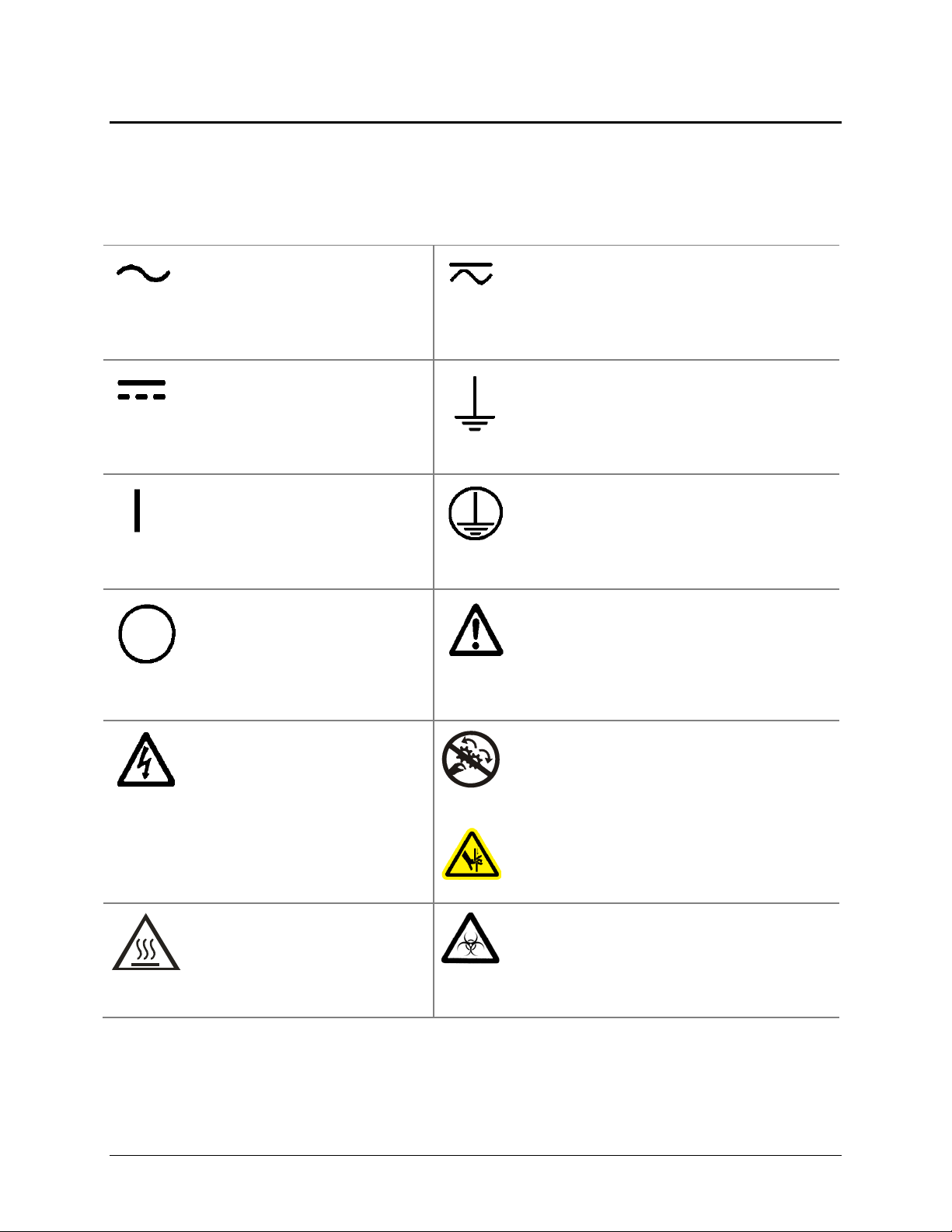
Safety Symbols
Some of these symbols may appear on the instrument or accessories:
Safety Symbols | xix
Alternating current
Courant alternatif
Wechselstrom
Corriente alterna
Corrente alternata
Direct current
Courant continu
Gleichstrom
Corriente continua
Corrente continua
On (Supply)
Marche (alimentation)
Ein (Verbindung mit dem Netz)
Conectado
Chiuso
Off (Supply)
Arrêt (alimentation)
Aus (Trennung vom Netz)
Desconectado
Aperto (sconnessione dalla
rete di alimentazione)
Both direct and alternating current
Courant continu et courant alternatif
Gleich - und Wechselstrom
Corriente continua y corriente alterna
Corrente continua e corrente alternata
Earth ground terminal
Borne de terre
Erde (Betriebserde)
Borne de tierra
Terra (di funzionamento)
Protective conductor terminal
Borne de terre de protection
Schutzleiteranschluss
Borne de tierra de protección
Terra di protezione
Caution (refer to accompanying documents)
Attention (voir documents
d’accompanement)
Achtung siehe Begleitpapiere
Atención (vease los documentos incluidos)
Attenzione, consultare la doc annessa
Warning, risk of electric shock
Attention, risque de choc
électrique
Gefährliche elektrische schlag
Precaución, riesgo de sacudida
eléctrica
Attenzione, rischio di scossa
elettrica
Warning, hot surface
Attention, surface chaude
Warnen, heiße Oberfläche
Precaución, superficie caliente
Attenzione, superficie calda
ELx808 Operator’s Manual
Warning, risk of crushing or pinching
Attention, risque d’écrasement et
pincement
Warnen, Gefahr des Zerquetschens und
Klemmen
Precaución, riesgo del machacamiento y
sejeción
Attenzione, rischio di schiacciare ed
intrappolarsi
Warning, potential biohazards
Attention, risques biologiques potentiels
Warnung! Moegliche biologische Giftstoffe
Atención, riesgos biológicos
Attenzione, rischio biologico
Page 22
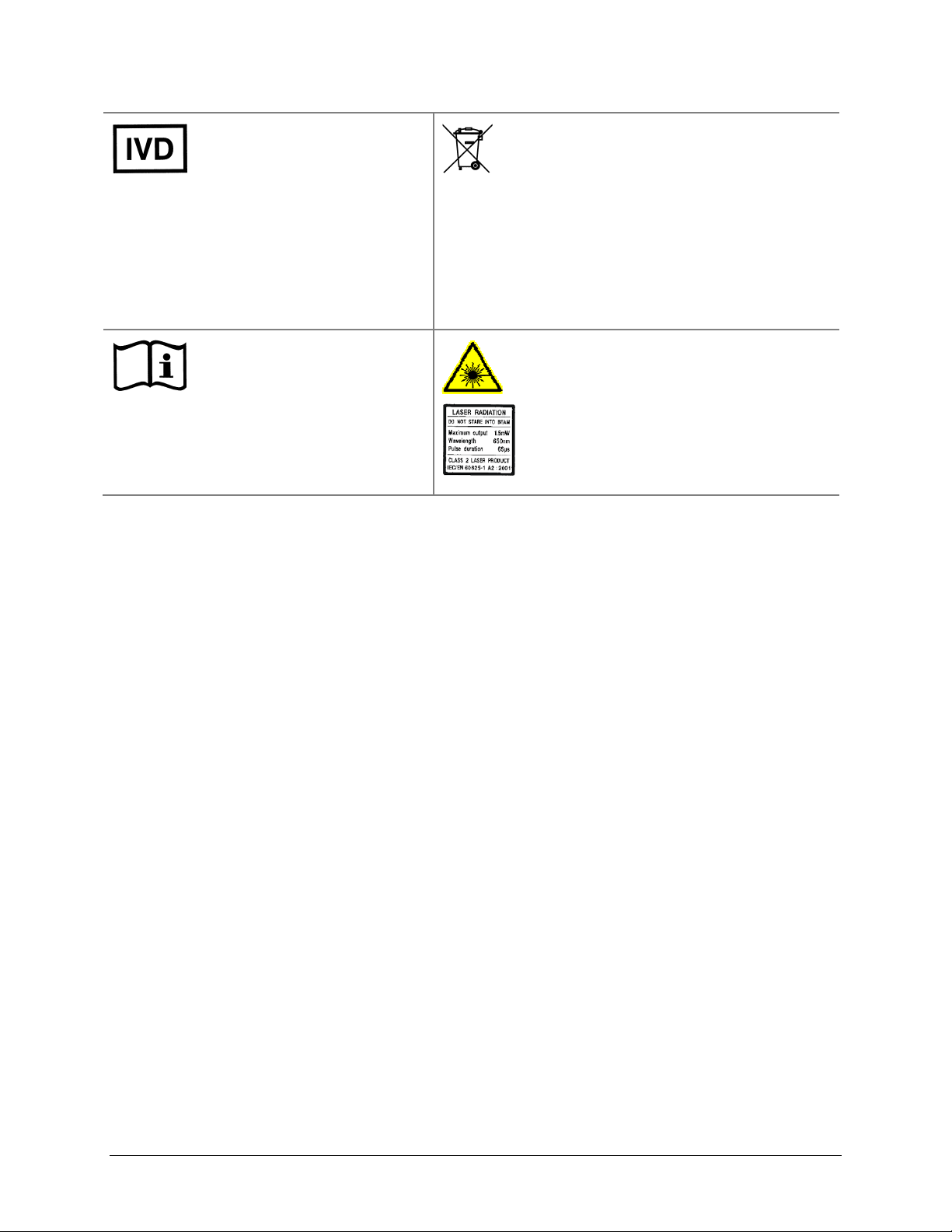
xx | Preface
In vitro diagnostic medical
device
Dispositif médical de
diagnostic in vitro
Medizinisches In-VitroDiagnostikum
Dispositivo médico de
diagnóstico in vitro
Dispositivo medico diagnostico
in vitro
Consult instructions for use
Consulter la notice d’emploi
Gebrauchsanweisung beachten
Consultar las instrucciones de
uso
Consultare le istruzioni per uso
Separate collection for electrical and
electronic equipment
Les équipements électriques et
électroniques font l’objet d’une collecte
sélective
Getrennte Sammlung von Elektro- und
Elektronikgeräten
Recogida selectiva de aparatos eléctricos y
electrónicos
Raccolta separata delle apparecchiature
elettriche ed elettroniche
Laser radiation: Do not stare into beam
Rayonnement laser: Ne pas regarder
dans le faisceau
Laserstrahlung: Nicht in den strahl
blicken
Radiación de láser: No mire fijamente al
rayo
Radiazione di laser: Non stare nel fascio
BioTek Instruments, Inc.
Page 23

Chapter 1
Introduction
This chapter introduces the ELx808 Absorbance Microplate Reader
and describes its hardware and software features, and technical
specifications. Instructions for contacting BioTek are provided on
page 7.
ELx808 Absorbance Microplate Reader .................................. 2
Reader Variations .......................................................... 2
Hardware Features ............................................................. 2
Software Features .............................................................. 3
Package Contents .............................................................. 3
Optional Accessories........................................................... 3
Specifications .................................................................... 4
Microplates ................................................................... 4
Electrical ...................................................................... 4
Physical ....................................................................... 4
Environmental .............................................................. 5
Hardware ..................................................................... 5
Reading Speeds ............................................................ 5
Standard Model: ELx808 ................................................ 5
Incubator/Ultraviolet Model: ELx808IU ............................. 6
Product Support and Service ............................................... 7
Contacting the Technical Assistance Center ....................... 7
Returning Instruments for Service/Repair ......................... 7
Page 24

2 | Chapter 1: Introduction
ELx808 Absorbance Microplate Reader
BioTek’s ELx808 is an eight-channel reader-assay system. The reader can serve as a
standalone system, or can be controlled via BioTek’s Gen5 software.
Designed to automatically perform endpoint and kinetic analysis, the reader can measure
the optical density of solutions in 96-well microplates between 380 nm and 900 nm. The
UV option measures down to 340 nm.
The reader features superior optical specifications, with an extended dynamic range of up
to 4.000 absorbance units.
The instrument’s onboard processor, 2-line x 24-character LCD screen, and membrane
keys allow easy definition and management of assay protocols, templates, formulas, and
data. Results can be output in a printed report format, or exported for use in a variety of
ELISA-based data manipulation applications.
Reader Variations
• ELx808: Absorbance Microplate Reader (standard model).
ELx808IU: Reader with incubation and UV capability. The ELx808IU has a four-
•
zone incubation chamber that controls temperatures up to 50°C, and is capable of
reading plates between 340 nm and 900 nm wavelengths.
Hardware Features
• Eight optics channels, with an additional reference channel
• A wavelength range of 380-900 nm (ELx808), 340-900 nm (ELx808IU)
• A user-accessible, 6-position filter wheel
• A 2-line x 24-character LCD display
• A membrane keypad with alphanumeric keys
• Adjustable plate shake frequency and times
• Reads 96-well microplates with 0.355" (9.017 mm) well centers
• Internal, four-voltage range power input module that can be adjusted for 100, 120,
230, or 240 V~ @ 50-60 Hz (readers manufactured before December 2005)
• 24-volt external power supply compatible with 100-240 V~ ± 10% @ 50-60 Hz
(readers manufactured after December 2005)
• One serial COM port (25-pin male) and one parallel port (25-pin female)
• 4-Zone incubation chamber option (ELx808IU)
BioTek Instruments, Inc.
Page 25

Software Features | 3
Software Features
• Easy-to-use, menu-driven interface
• Endpoint, Kinetic, and Linear Well scanning calculations
• Curve fitting, with 4-parameter, cubic, quadratic, linear, 2-P, cubic-spline and
point-to-point methods
• Transformation and formula calculations for more complex mathematical
operations, including validation and cutoff formulas
• 55 assays are available onboard; up to 75 custom assays can be preprogrammed
and exported to the reader using BioTek’s Define Protocol software.
• Automatically stores results for the last 10 plates.
Package Contents
Package contents and part numbers are subject to change. Please
contact BioTek Customer Care with questions.
• ELx808 Absorbance Microplate Reader
• Power cord (PN varies according to country of use)
• Power supply for readers manufactured after December 2005 (PN 01281)
• Filter wheel with four standard filters: 405 nm, 450 nm, 490 nm, 630 nm and two
blank filters. The ELx808IU also includes a 340 nm filter.
• Operator’s Manual (PN 7341000)
• Serial cable (PN 75053)
• Dust cover (PN 7342066)
Optional Accessories
Accessory availability and part numbers are subject to change. Contact
BioTek Customer Care with questions, or visit www.biotek.com and
use the Accessories search tool.
• Additional filters (please inquire for availability):
¾ 340 to 630 nm, PN 3100XXX (XXX is wavelength in nanometers)
¾ 640 to 900 nm, PN 3404XXX (XXX is wavelength in nanometers)
ELx808 Operator’s Manual
Page 26

4 | Chapter 1: Introduction
• Replacement lamp assembly (PN 3400508)
• Filter wheel plug (PN 3122037)
• Absorbance Test Plate (PN 9000547 or PN 7260522)
• ELx808 IQ/OQ/PQ Package (PN 7340543)
• Gen5 Software (visit biotek.com or contact your local dealer for details)
• Absorbance Liquid Test Solutions:
¾ BioTek QC Check Solution No. 1 (PN 7120779, 25 mL; PN 7120782, 125 mL)
¾ BioTek wetting agent (PN 7773002)
• Adapter to connect the reader to a USB-only printer (PN 75135)
Specifications
Microplates
• Standard 96-well, flat- or round-bottom plates
Electrical
• Power source and voltage range:
¾
Readers manufactured after December 2005: 24-volt external power
supply compatible with 100-240 V~ ± 10% @ 50-60 Hz
¾
Readers manufactured before December 2005: Internal, adjustable
power input module with four voltage ranges accommodated by the voltage
selection switch:
Range 1 100 V~ 90 to 110 V~, 50 to 60 Hz
Range 2 120 V~ 108 to 132 V~, 50 to 60 Hz
Range 3 230 V~ 207 to 253 V~, 50 to 60 Hz
Range 4 240 V~ 216 to 264 V~, 50 to 60 Hz
• Power consumption: 100 VA
Physical
• Dimensions: 16.0" D x 15.5" W x 8.75" H (40.6 cm x 39.37 cm x 22.2 cm)
Weight: 35 lb. maximum (15.87 kg maximum)
•
BioTek Instruments, Inc.
Page 27

Specifications | 5
Environmental
• Operating temperature: 18° to 40°C (64° to 104°F)
Humidity: 10% to 85% noncondensing
•
Hardware
• Light source: Tungsten halogen-filled bulb
Display: 2-line x 24-character LCD
•
Reading Speeds
• Single wavelength: 8 seconds rapid mode; 12 seconds normal/regular mode
Dual wavelength: 13 seconds rapid mode; 20 seconds normal/regular mode
•
Single wavelength higher than 400 nm: 6-second minimum kinetic interval,
•
rapid mode
Standard Model: ELx808
The following specifications apply only to standard 96-well, flat- or
round-bottom microplates.
• Wavelength Range: 380 to 900 nm
Filters: 10 nm half-bandwidth interference filters. User-accessible filter wheel.
•
Up to 6 filters may be installed on the instrument at one time. Filters supplied:
405 nm, 450 nm, 490 nm, 630 nm, and two blank filters.
Absorbance Measurement Range: 0.000 to 4.000 OD
•
Optical specifications for single-wavelength endpoint measurements with a 12second read (normal/regular read mode):
Accuracy: ± 1.0% ± 0.010 OD from 0.000 to 2.500 OD @ 405 nm
Linearity: ± 1.0% from 0.000 to 2.500 OD at 405 nm
± 2.0% from 2.500 OD to 3.500 OD @ 405 nm
Repeatability: ± 0.5% ± 0.005 OD from 0.000 to 2.500 OD @ 405 nm
± 1.5% ± 0.005 OD from 2.500 to 3.500 OD @ 405 nm
± 2.5% ± 0.005 OD from 3.500 to 4.000 OD @ 405 nm
ELx808 Operator’s Manual
Page 28

6 | Chapter 1: Introduction
Optical Specifications for single-wavelength kinetic measurements with read
intervals of less than 12 seconds:
Accuracy: ± 2.0% ± 0.010 OD from 0.000 to 2.500 OD @ 405 nm
Linearity: ± 2.0% from 0.000 to 2.500 OD @ 405 nm
Repeatability: ± 1.0% ± 0.010 OD from 0.000 to 2.500 OD @ 405 nm
The plate can be read at 6-second intervals (rapid mode) with
wavelengths higher than 400 nm.
Incubator/Ultraviolet Model: ELx808IU
The following specifications apply only to standard 96-well,
flat- or round-bottom microplates.
• Wavelength Range: 340 to 900 nm
Filters: 10 nm half-bandwidth interference filters. User-accessible filter wheel.
•
Up to 6 filters may be installed on the instrument at one time. Filters supplied:
340, 405, 450, 490, 630 nm.
Absorbance Measurement Range: 0.000 to 4.000 OD for 400 to 900 nm range,
•
0.000 to 3.000 OD for 340 to 400 nm range
Optical specifications for the 400 to 900 nm range (12-second read in normal/
regular read mode):
Accuracy, Linearity, Repeatability: Same as Standard Model.
Optical specifications for the 340 to 400 nm range (12-second read in normal/
regular mode):
Accuracy: ± 1.0% ± 0.010 OD from 0.000 to 2.000 OD @ 340 nm
Linearity: ± 1.0% from 0.000 to 2.000 OD @ 340 nm
Repeatability: ± 1.0% ± 0.005 OD from 0.000 to 2.000 OD @ 340 nm
•
Incubation: The following specifications apply to a 96-well sealed plate with
200 μL of liquid in all wells:
Temperature Control: Temperature controlled to 50°C
¾
Temperature Variation: ± 0.50°C @ 37°C with the plate sealed
¾
BioTek Instruments, Inc.
Page 29

Product Support and Service | 7
Product Support and Service
If your instrument or software fails to function properly, if you have questions about how
to use or maintain your products, or if you need to send an instrument to BioTek for
service or repair, please contact our Technical Assistance Center (“TAC”).
Contacting the Technical Assistance Center
TAC is open from 8:30 AM to 5:30 PM (EST), Monday through Friday, excluding
standard U.S. holidays. You can send a fax or an e-mail any time.
Phone: 800-242-4685 (in the U.S.) or 802-655-4740 (outside the U.S.)
Fax: 802-654-0638
E-Mail: tac@biotek.com
Web: www.biotek.com
Please be prepared to provide the following information:
• Your name and company information
• A daytime phone or fax number, and/or an e-mail address
• The product name, model, and serial number
• The onboard software part number and version (available via the keypad
by selecting
• Gen5 software version information (
UTIL > TESTS > CHKSUM)
Help > About Gen5).
Returning Instruments for Service/Repair
If you need to return an instrument to BioTek for service or repair, please contact the
TAC for a Return Materials Authorization (RMA) number and the shipping address.
Repackage the instrument according to the instructions at the end of
Installation
.
Chapter 2:
ELx808 Operator’s Manual
Page 30

8 | Chapter 1: Introduction
BioTek Instruments, Inc.
Page 31

Chapter 2
Installation
This chapter includes instructions for unpacking and setting up the
ELx808, and instructions for connecting printers and/or serial
devices.
Product Registration ......................................................... 10
1: Unpack and Inspect the Instrument ................................ 10
2: Select the Operating Environment .................................. 11
3: Install the Filter Wheel .................................................. 12
4: Check/Adjust the Power Input Voltage Setting ................. 14
5: Connect Power ............................................................ 14
6: (Optional) Connect Printer ............................................. 15
Printers ...................................................................... 16
7: Turn on Reader and Run System Test ............................. 16
8: Check/Adjust the Reader’s Filter Table ............................ 17
9: Configure Reader Settings ............................................. 18
SETUP Options ............................................................ 18
OUTPUT Options .......................................................... 19
REPORT Type .............................................................. 19
READ Options ............................................................. 20
Read Speed ................................................................ 21
10: Install Software/Connect to Computer (Optional) ............ 21
Attach the Cable ......................................................... 21
Install Gen5 Software on the Host Computer ................... 21
Establish Communication .............................................. 22
Changing the Baud Rate on the ELx808 .......................... 22
11: Verify Performance ..................................................... 23
Before Repackaging the Instrument .................................... 24
Page 32

10 | Chapter 2: Installation
Product Registration
Please register your product(s) with BioTek to ensure that you receive important
information and updates about the product(s) you have purchased. Register online
through BioTek’s Customer Resource Center (CRC) at www.biotek.com or by contacting
BioTek Customer Care.
1: Unpack and Inspect the Instrument
Important! Save all packaging materials! If you need to
ship the reader to BioTek for repair or replacement, you must
use the original packaging materials. Using other forms of
commercially available packaging materials is not
recommended and can void the warranty. Improper
packaging that results in damage to the instrument may lead to
additional charges.
If the original packaging materials have been damaged or lost,
contact BioTek and ask for PN 7343000. See Product Support
& Service in Chapter 1 for contact information.
See Before Repackaging the Instrument at the end of this
chapter for complete shipping instructions.
The instrument’s packaging is subject to change. If the instructions in this
section do not apply to the packaging materials you are using, please contact
BioTek’s Technical Assistance Center for guidance.
The ELx808 and its accessories are securely packaged inside custom-designed shipping
materials. This packaging should protect the instrument from damage during shipping.
Inspect the shipping box, packaging, instrument, and accessories for signs of damage.
If the shipping box has been damaged: Inspect the instrument for visible dents and
scratches as you unpack it.
If the reader is damaged:
Keep the shipping cartons and the packing materials for the carrier’s inspection. BioTek
will arrange for repair or replacement of your reader immediately.
Notify the carrier and your BioTek sales representative.
1. (Refer to Figure 1 on the next page.) Carefully open the top of the box, and
remove any accessories. These include a power cord and power supply, a filter
wheel in a padded envelope, and an operator’s manual.
2. Remove the end caps from the reader.
BioTek Instruments, Inc.
Page 33

2: Select the Operating Environment | 11
3. Lift the reader out of the box, and place it on a level surface. Remove the reader
from the plastic bag.
4. Remove the filter wheel from the shipping envelope
5. Place all packing material back into the shipping box for reuse if the instrument
needs to be shipped again.
Figure 1: Unpacking the ELx808
2: Select the Operating Environment
For best operation, install the reader on a level surface in an area where ambient
temperatures between 18°C (64°F) and 40°C (104°F) can be maintained.
The reader is sensitive to extreme environmental conditions. Conditions to avoid are:
•
Excessive humidity: Condensation directly on the sensitive electronic
circuits can cause the instrument to fail internal self-checks. The humidity must
be in the range of 10% to 85%, noncondensing.
Excessive ambient light: Bright sunlight or strong incandescent light can
•
reduce the linear performance range and affect the instrument’s readings.
ELx808 Operator’s Manual
Page 34

12 | Chapter 2: Installation
• Dust: Optical density readings may be affected by extraneous particles (such
as dust) in the microplate wells. A clean work area is necessary to ensure
accurate readings.
3: Install the Filter Wheel
The filters that ship with the ELx808 are installed in the six-position filter wheel. For
example, the standard models have 405, 450, 490, 630 nm filters; the UV model’s filter set is
405, 450, 490, 630 and 340 nm.
The filter wheel, which is packaged in a shipping envelope, must be installed before the
reader is used. If you plan to install additional filters, or change the filter locations, use the
following instructions to gain access to the filter wheel (refer to
Figure
2 on page 13):
1. If the reader is on, turn it off and disconnect the power cord or power supply.
2. Remove the seven screws around the perimeter of the shroud with a
screwdriver.
Tip: Bring the reader to the edge of the work surface to access the screws
without having to turn the reader upside down.
3. Carefully lift up the shroud from the front. (Note that the shroud is hinged along
its back edge.) Hold the plate access door steady, or tape it closed as the shroud
is being lifted to prevent the door from moving.
4. Ensure that all locations on the filter wheel contain either a filter or a blank. Each
location on the filter wheel must be occupied for the reader to operate properly.
Take a moment to record the filter values in each location
(e.g., 405 nm in position 1).
Important! Keep track of all filter locations. The physical
location of the filters must match the filter locations mapped in
the reader’s software filter table. The filter wheel must have no
empty locations; all locations must be filled with either a filter
or a blank plug. Install all filters with the arrow denoting the
light direction pointing downward.
5. The filter wheel mount is located in the left-rear corner inside the reader. The
filter wheel is held in place by a magnet on the filter wheel motor hub. To install
the filter wheel:
• Line up the registration notch on the hub and the corresponding peg on the
filter wheel.
• Apply firm pressure to attach the filter wheel to the hub. The peg must be
engaged in the notch for proper installation.
BioTek Instruments, Inc.
Page 35

3: Install the Filter Wheel | 13
• Ensure that the filter wheel is positioned flat against the hub and that it
rotates freely.
• Lower the top shroud back into position and remove tape if used to steady
the plate access door.
• Reinstall the seven screws removed from the perimeter of the shroud.
Important! Be sure to replace the seven perimeter screws;
6. To remove the filter wheel, grasp the center hub of the filter wheel and pull it
toward the lamp. The wheel should easily disconnect from the hub. Lift the
wheel from the instrument.
7. To properly store interference filters for the ELx808 during extended periods of
non-use, package the filters in a light-tight envelope or container, away from
high humidity and direct sunlight. This will ensure the longest life for the filters.
When handling the filters, keep the surfaces clean from fingerprints and debris
by simply wiping with a lens tissue or other lint-free cloth.
they increase the reader’s ability to withstand electrostatic
discharges and electromagnetic interference. In addition, the
screws MUST be installed to hold the shroud in place if you
plan to ship the instrument back to BioTek for service or repair.
Figure 2: Installing the Filter Wheel
ELx808 Operator’s Manual
Page 36

14 | Chapter 2: Installation
4: Check/Adjust the Power Input Voltage Setting
For ELx808 readers manufactured before December 2005 only: The reader is
powered by an internal, adjustable four-voltage range power input module, instead of by
an external power supply. For instructions for checking or adjusting the power input
voltage setting, and for reconfiguring or replacing the fuses, refer to
Adjusting the Power Input Voltage Setting.
Appendix C,
5: Connect Power
ELx808 with the external power supply:
1. Connect the power cord to the external power supply.
2. Locate the power inlet on the right side of the reader.
3. Plug the rounded end of the power supply’s line cord into the power inlet.
4. Plug the other end of the power cord into an appropriate power receptacle.
ELx808 with the internal power input module:
1. Locate the power inlet on the right side of the reader.
2. Plug the rounded end of the power cord into the power inlet.
3. Plug the other end of the cord into an appropriate power receptacle.
Warning! Power Rating. The ELx808 or power supply
must be connected to a power receptacle that provides voltage
and current within the specified rating for the system. Use of
an incompatible power receptacle may produce electrical
shock and fire hazards.
Warning! Electrical Grounding. Never use a plug adapter
to connect primary power to the ELx808 power supply. Use of
an adapter disconnects the utility ground, creating a severe
shock hazard. Always connect the power supply cord directly
to an appropriate receptacle with a functional ground.
BioTek Instruments, Inc.
Page 37

6: (Optional) Connect Printer | 15
6: (Optional) Connect Printer
If the ELx808 will operate in standalone mode (that is, without BioTek’s Gen5 software
running on a host PC), connect a printer directly to the reader using the supplied cable.
Important! To avoid system instability, make sure the printer
1. If the reader and/or printer are on, turn them off. Place the printer in a location
adjacent to the reader.
2. Attach one end of the parallel cable to the printer’s parallel port.
3. Attach the other end of the cable to the reader’s parallel port, located on the
instrument’s rear panel.
4. Make sure the securing screws on both ends of the cable are tightened.
5. Turn on the printer.
and reader are turned OFF before connecting them.
Figure 3: Serial and parallel ports
ELx808 Operator’s Manual
Page 38

16 | Chapter 2: Installation
Printers
The ELx808’s parallel port (LPT1) allows connection to compatible printers. The reader
supports printers using either HP's PCL3 language, such as the HP DeskJet series, or
Epson's LQ language. For a list of compatible printers call BioTek's Technical
Assistance Center or visit our website (refer to
Chapter 1 for contact information).
7: Turn on Reader and Run System Test
If all of the required steps preceding this one have been performed successfully, locate the
reader’s power switch (on the right side) and turn on the reader. The ELx808 will
automatically perform a System Test. The System Test conducts a series of tests at each
wavelength defined in the filter table to confirm adequate light levels, low electronic noise,
adequate photodiode sensitivity, overall system cleanliness, and (if equipped) proper
function of the incubator. The testing verifies that the reader will give in-specification
performance for each set wavelength over the specified OD range.
If a printer is connected to the reader, the test results automatically print. This test can also
be run through Gen5 running on a host PC; consult the Gen5 Help system for instructions.
• If the test passes, the reader will beep once and the display will show the
software’s main menu, which will resemble one of the following:
Standard ELx808:
R E A D Y 0 1 : 3 0 P M 1 0 / 0 9 / 1 0
R E A D D E F I NE R E P O R T U T I L
ELx808IU:
R E A D Y 0 1 : 3 0 P M 3 7 . 0 º C
R E A D D EFINE REPORT U T I L
• If the test fails, the reader will beep repeatedly and the display will show an
error code. If this happens, write down the error code and then press the
key on the keypad to stop the beeping. Look up the error code in
Error Codes to determine its cause.
Chapter 6,
STOP
If the problem is something you can fix (for example, if the error code is 0201
or 0301, indicating that the filter wheel is missing), turn off the reader, fix the
problem, and then turn the reader back on. If the cause is not something you
can fix, contact BioTek’s Technical Assistance Center. See
Introduction
for contact information.
Chapter 1,
BioTek Instruments, Inc.
Page 39

8: Check/Adjust the Reader’s Filter Table | 17
8: Check/Adjust the Reader’s Filter Table
After installing the filter wheel (or new filters), ensure that the ELx808’s filter table
accurately maps the physical location of the filters in the filter wheel.
1. Turn on the reader if it is not already on.
2. At the Main Menu screen, select UTIL.
R E A D Y 0 1 : 3 0 P M 1 0 / 0 9 / 1 0
R E A D D E F I N E R E P O R T U T I L
The SELECT UTILITY OPTION menu appears:
S E L E C T U T I L I T Y O P T I O N :
T E S T S S E T U P O U T P U T R E A D
3. From the Select Utility Option menu, select SETUP. The EDIT SETUP
INFORMATION screen appears:
E D I T S E T U P I N F O R M A T I O N :
D A T E T I M E F I L T E R * M O R E
4. Select FILTER. The wavelength currently defined for Filter #1 appears:
E N T E R
F I L T E R # 1 W A V E L E N G T H : 4 0 5
If you need to change the filter wavelength number, use the numeric keypad to
enter a number at the cursor location. To save the entry and move to the next
filter on the filter table, press the
entered, the software exits the filter routine, and displays the following screen:
Enter key. When the last filter has been
E D I T S E T U P I N F O R M A T I O N :
D A T E T I M E F I L T E R * M O R E
5. Press the Main Menu key to return to the Main Menu.
ELx808 Operator’s Manual
Page 40

18 | Chapter 2: Installation
9: Configure Reader Settings
The ELx808 may be configured a number of ways, depending on user preference.
Configuration options are accessed via the Select Utility Option menu, and include:
SETUP: Set the date and time.
•
OUTPUT: Select whether reports will be output to a Printer, the Computer, or
•
both, choose the Column or Matrix report format, and determine if Curves will
be printed.
READ: Indicate whether prompts shall be displayed at run-time for Plate IDs,
•
Sample IDs, and Sample Counts.
TESTS: Access functions to test reader optics and instrument calibration.
•
Check the version of basecode software installed. See
Instrument Qualification
for more information.
To select the SETUP, OUTPUT, and READ user-configurable options:
Chapter 4,
• At the Main Menu screen, select
S E L E C T U T I L I T Y O P T I O N :
T E S T S S E T U P O U T P U T R E A D
SETUP Options
1. At the Select Utility Option screen, select SETUP.
E D I T S E T U P I N F O R M A T I O N :
D A T E T I M E F I L T E R * M O R E
2. At the Edit Setup Information screen, select DATE.
D A T E : 1 0 / 0 9 / 0 7 M D Y
M M D D Y Y D D M M Y Y
3. Enter the new date, using the numeric keys. The cursor is positioned under the
first editable field, and advances automatically. To change the date format, select
MMDDYY or DDMMYY. The display updates to reflect the new format.
UTIL to access the Select Utility Option menu.
4. Press Enter to return to the Edit Setup Information screen.
T I M E : 0 3 : 1 1 P M 1 2 H R
1 2 H O U R 2 4 H O U R A M / P M
BioTek Instruments, Inc.
Page 41

5. To edit the Time, select TIME. At the Time Entry Screen, use the numeric keys to
enter the correct time.
6. Select a 12- or 24-hour format by pressing the soft key beneath these options. The
display automatically updates with the new time AM/PM format.
7. Press the Previous Screen key to return to the Select Utility Option menu.
OUTPUT Options
1. At the Select Utility Option screen, select OUTPUT to set report output
preferences.
R E P O R T O U T P U T ? B O T H
P R I N T C O M P U T E R B O T H
2. Any previously defined selection appears on the top line of the display. Select
the desired option (PRINT, COMPUTER, BOTH) to change the output device.
9: Configure Reader Settings | 19
3. Press Enter to advance to the Select Printer menu screen. If COMPUTER is
selected, all results will be transferred directly to the computer screen via the
RS232 serial port.
S E L E C T P R I N T E R E P S O N
E P S O N H P
REPORT Type
These selections only apply when the reader is run in standalone mode
(without Gen5). See Appendix A for examples of Reports.
1. At the Select Printer screen, press Enter to advance to the REPORT TYPE menu
screen.
R E P O R T T Y P E : M A T R I X
C O L U M N M A T R I X B O T H
2. The current selection appears on the top line of the display. Select the desired
option (COLUMN, MATRIX, BOTH) to change the Report Type.
ELx808 Operator’s Manual
Page 42

20 | Chapter 2: Installation
3. Press Enter to advance to the SAMPLES ON COL RPT screen.
S A M P L E S O N C O L R P T ? N O
Y E S N O
4. Select YES to print samples on the column report, or NO to omit them.
5. Press Enter to advance to the PRINT CURVE-FIT screen.
P R I N T C U R V E - F I T ? N O
Y E S N O
6. The current selection is displayed on the top line of the screen. To change the
report option, select
(Select YES if there are quantitative assays defined on board and you wish to
print the curve.)
7. Press Enter to return to the Select Utility Option screen.
YES or NO. The display updates to reflect the selection.
READ Options
1. At the Select Utility Option screen, press the soft key beneath READ to set up
Reader Prompt preferences. Select
identifications and sample counts before a microplate is read. The prompts are
shown below.
2. Press Enter after each selection to advance the display.
P R O M P T F O R P L A T E I D ? N O
Y E S N O
3. PROMPT FOR PLATE ID allows the user to enter an alphanumeric name of up
to 10 characters. Select
P R O M P T F OR S A M P L E I D ? N O
Y E S N O
4. PROMPT FOR SAMPLE ID allows the user to identify samples with a
4-character alphanumeric name. The starting ID is entered and automatically
incremented by the software. Select
YES to prompt the operator to enter
YES to present this prompt at run-time.
YES to present this prompt at run-time.
P R O M P T S A M P L E C O U N T ? N O
Y E S N O
BioTek Instruments, Inc.
Page 43

5. PROMPT SAMPLE COUNT allows the user to enter the total number of samples
on the plate at runtime; only those sample results will be printed. Select
present this prompt at run-time.
Read Speed
R E A D I N R A P I D M O D E ? N O
Y E S N O
10: Install Software/Connect to Computer (Optional) | 21
YES to
RAPID MODE
than 400 nm. Selecting NO means a plate with single-wavelength kinetic
measurements will be read in intervals less than 12 seconds (“Regular” or “Normal”
Mode). Specifications for these modes are outlined in
reads a 96-well plate at 6-second intervals with wavelengths higher
Chapter 1.
10: Install Software/Connect to Computer (Optional)
The ELx808 has serial (RS232) port located on back of the reader (see Figure 3 on page 15).
This port allows the reader to communicate with a computer using the BioTek Gen5
software. It also allows for upgrades to the ELx808 basecode (on-board) software.
Attach the Cable
• Turn off the computer and the reader.
• Connect the supplied serial cable to both machines.
Install Gen5 Software on the Host Computer
If applicable, install Gen5 on the host computer. There is a
ELx808 Operator’s Manual
certain sequence of events that must be followed to ensure
that the software is properly installed and configured. Please
follow the instructions provided in Gen5 Getting Started
Guide to install the software.
Page 44

22 | Chapter 2: Installation
Establish Communication
1. Start Gen5 and log in if prompted. The default System Administrator password is
admin.
2. Go to the Gen5 main screen:
• Gen5 version 2.x users: From the Task Manager, select
Menu.
• Gen5 version 1.x users: From the Welcome screen, select
3. Select System > Instrument Configuration and click Add.
4. Set the Reader Type to ELx808.
5. Set the Com Port to the computer’s COM port to which the reader is connected.
6. Click Test Comm. Gen5 attempts to communicate with the reader. If the
Setup > Go to System
System Menu.
communication attempt is successful, return to the Gen5 main screen.
If the communication attempt is
not successful, try the following:
• Is the reader connected to the power supply and turned on?
• Is the communication cable firmly attached to both the reader and the
computer?
• Did you select the correct Reader Type in Gen5?
• Try a different COM port.
• Make sure the reader display is at its Main Menu.
If you remain unable to get Gen5 and the reader to communicate with each other,
contact BioTek’s Technical Assistance Center.
Changing the Baud Rate on the ELx808
Gen5 requires the baud rate to be set to 9600.
If you need to change the baud rate from the default of 9600 to either 1200 or 2400:
1. Turn on the instrument if it is not already on.
R E A D Y 0 1 : 3 0 P M 1 0 / 0 9 / 0 7
R E A D D E F I NE R E P O R T U T I L
2. At the Main Menu screen, select UTIL.
S E L E C T U T I L I T Y O P T I O N :
T E S T S S E T U P O U T P U T R E A D
BioTek Instruments, Inc.
Page 45

11: Verify Performance | 23
3. At the Select Utility Option screen, select SETUP.
E D I T S E T U P I N F O R M A T I O N :
D A T E T I M E F I L T E R * M O R E
4. At the Edit Setup Information screen, select *MORE to advance to the EDIT
SETUP / RS232 option screen.
E D I T S E T U P I N F O R M A T I O N :
R S 2 3 2 C A L P L A T E * M O R E
5. Select RS232 to access the Select Baud Rate menu. The top line of the
display shows the baud rate currently set.
S E L E C T B A U D R A T E : 9 6 0 0
1 2 0 0 2 4 0 0 9 6 0 0 V I E W
6. To change the Baud rate, press the soft key beneath the desired baud rate.
The display (top line) automatically updates to reflect the new choice.
7. To view the reader’s settings for parity, stop bits, and data bits, select
VIEW.
11: Verify Performance
Before using the ELx808 for the first time, verify that the reader is operating properly by
running a System Test and the Absorbance Plate Test. These tests and additional
verification procedures are described in
Chapter 4, Instrument Qualification.
ELx808 Operator’s Manual
Page 46

24 | Chapter 2: Installation
Before Repackaging the Instrument
Important! Use the instrument’s original shipping container
and packaging material. This shipping system was designed to
be used no more than five times. If the container is damaged
and/or has been used more than five times, contact BioTek for
a new set of shipping materials, and ask for PN 7343000.
The instrument’s packaging design is subject to change. If the
instructions in this section do not appear to apply to the
packaging materials you are using, please contact BioTek’s
Technical Assistance Center for guidance.
Warning! If the reader has been exposed to potentially
hazardous material, decontaminate it to minimize the risk to
all who come in contact with the reader during shipping,
handling, and servicing. Decontamination prior to shipping is
required by U.S. Department of Transportation regulations
1. Decontaminate the reader prior before shipping. Refer to Decontamination in
Chapter 5, Preventive Maintenance, for instructions.
2. Once the reader is clean, pack it in its original shipping box, using the original
packing materials (see
3. Contact BioTek’s Technical Assistance Center for a Return Materials
Authorization (RMA) number and shipping instructions.
Figure 1 on page 11).
BioTek Instruments, Inc.
Page 47

Chapter 3
Operation
This chapter includes instructions for operating the ELx808 Reader
and its software.
Getting Started with Gen5 ................................................. 27
Introduction .................................................................... 28
The Keypad ................................................................ 29
The Startup Screen ...................................................... 30
The Main Menu Screen ................................................. 30
Quick Read ................................................................. 31
Defining Assays ............................................................... 32
Selecting an Assay ...................................................... 32
Assay Name ............................................................... 32
Defining the Method, Map, Formula, and Curve ................ 33
METHOD .................................................................... 34
MAP .......................................................................... 40
FORMULA ................................................................... 53
CURVE ....................................................................... 64
Panel Assays .............................................................. 67
Reading a Microplate ........................................................ 70
Select Assay ............................................................... 70
Run-Time Prompts ....................................................... 70
Enter Number of Samples ............................................. 71
Enter Plate ID ............................................................. 71
Enter Sample ID ......................................................... 71
Prompts for Well Location ............................................. 72
Page 48

26 | Chapter 3: Operation
Beginning the Plate Read .............................................. 72
Printing Reports and Assay Lists ......................................... 73
Result ........................................................................ 74
Editing Standard Outliers .............................................. 74
Printing Results ........................................................... 75
Map ........................................................................... 75
Assay ........................................................................ 76
List ........................................................................... 76
Recommendations for Optimum Performance ....................... 76
Some readers have custom programmed assays installed.
Not all features of the software discussed in this chapter are
available on custom instruments. Please contact BioTek’s
Technical Assistance Center (TAC) if you have any questions
about the assays on your reader
All users should read Recommendations for Optimum
Performance on page 76.
BioTek Instruments, Inc.
Page 49

Getting Started with Gen5 | 27
Getting Started with Gen5
These instructions describe how to create and run an Experiment in Gen5. For more
information, or if the instructions below do not match what you see in Gen5, refer to the
Gen5 Getting Started Guide and help system.
Gen5 version 2.x users:
1. Start Gen5.
2. If the Task Manager appears, select Read Now > New and skip to step 4.
Otherwise, select
3. Select Read Now > New. Gen5 will open the procedure dialog. Go to step 4.
Gen5 version 1.x users:
1. Start Gen5. If the Welcome screen appears, select Read a Plate and skip to
step 4. Otherwise, select
2. Click Default Protocol and click OK. Gen5 will open the Experiment
workspace, which includes the Protocol menu tree and Plate screen.
File > New Task from the main view.
File > New Experiment from the main view.
3. Select Plate > Read or click the Read Plate icon. The Procedure dialog will
open. Go to step 4.
For any version:
4. Select a Plate Type.
5. Click Read to open the Read Step dialog.
6. Select a Read Type.
7. Select or enter the wavelength(s) at which the plate will be read.
8. Define other reading parameters as desired. Click Help for assistance.
9. When complete, click OK to return to the Procedure dialog.
10. Click OK to save and close the Procedure dialog.
• Gen5 version 1.x only: The Plate Reading dialog will open. Enter any
desired information, place the plate on the carrier, then click
begin the plate read. If the Save As dialog opens, enter a File name,
choose a file location (Save in:) and click
11. Click OK when the Load Plate dialog appears. The plate will be read.
Save.
• To view the raw data results, use the Data drop-down arrow in the
Plate screen to select one wavelength. The results will be displayed for
the selected wavelength. Repeat, for other wavelengths.
READ to
• To analyze, manipulate, or print results, Protocol parameters should be
defined. Refer to the Gen5 Help system for instructions.
ELx808 Operator’s Manual
Page 50

28 | Chapter 3: Operation
Introduction
The front panel on the ELx808 Reader features a 25-pad keypad and a 2-line x 24-character
LCD display as the user interface (see
port allows computer control of the instrument and provides the means for downloading
additional assay protocols to the instrument.
Figure 4 below). The reader’s bidirectional serial
Figure 4: ELx808 Front Panel with LCD and Keypad
BioTek Instruments, Inc.
Page 51

The Keypad
Introduction | 29
Main
Menu
Options
ENTER
Previous
Screen
CLEAR
Use the four “soft keys,” located directly below the display, to select
options presented on the display. For example, from the
press the leftmost soft key to select
READ, the rightmost to select UTIL.
Main Menu,
Exit the current screen and return to the Main Menu. After defining a
reader program, press the
Main Menu key, then press YES to save the
program.
To scroll through the different options within a program, press the
Options key or the Shift + Options key combination. Press the
Enter key to select the current option.
Pressing
Enter generally saves the current screen settings and
advances to the next screen in a series.
To move to a previous menu, press the
Press
Clear to clear/reset the current value on the reader’s LCD
Previous Screen key.
display.
◄
►
READ
STOP
Press the ◄ (reverse) arrow to move the cursor to the left in the LCD
display.
Press the ► (forward) arrow to move the cursor to the right in the LCD
display.
To start running a reader program, press the
Read key.
To stop running (abort) a reader program, press the
Stop key.
ELx808 Operator’s Manual
Page 52

30 | Chapter 3: Operation
The Startup Screen
To turn on the ELx808, press the on/off switch on the right side of the reader’s
base. The ELx808 will perform a system self-test, displaying the screens shown
below until initialization is complete. During this time, all keys are inactive.
If the self-test fails, the reader will “beep” and display an error code. Press
stop the beep. Refer to
BioTek Instrument’s Technical Assistance Center (see page 7), for further
assistance with troubleshooting.
P O W E R U P S E Q U E N C E V X . X X
I N I T I A L I Z I N G . . .
B I O T E K E L X 8 0 8
S E L F - T E S T . . . . .
The Main Menu Screen
Following successful power-up of the ELx808, the Main Menu screen is displayed.
This screen will vary slightly if the instrument has the Incubation/UV option:
Main Menu screen – ELx808
R E A D Y 0 1 : 3 0 P M 1 0 / 0 9 / 0 7
Stop to
Chapter 6, Error Codes, to interpret these codes. Contact
R E A D D E F I N E R E P O R T U T I L
Main Menu screen – ELx808IU (model with incubation/UV capability)
R E A DY 01:30PM 37. 0 º C
R E A D D E FINE REPORT U T I L
Note: The temperature indicated on the display of incubated models is
the actual averaged temperature of the incubator’s four zones. The
applied setpoint of the last assay is used. To adjust the temperature, a
new setpoint value must be assigned to the assay before running.
BioTek Instruments, Inc.
Page 53

The keyboard’s four “soft keys,” located below the on-screen menu options
(
READ, DEFINE, REPORT and UTIL), are activated, and may be selected. Press
the soft key that corresponds to a displayed menu option to select that option:
•
•
•
•
Quick Read
On some readers, Assay 01 has been designed to allow for quick and simple
assay programming. It appears as
options available in Assays 2 through 55, and described in this section, are
unavailable for programming within Quick Read. You can access the Quick Read
assay when
Introduction | 31
READ option: Initiate a plate read (or, press the key labeled READ on the
keyboard for plate reading prompts). You will be prompted to select from a
list of available assays.
DEFINE option: Create a reading and data reduction protocol. You will be
prompted to select/edit an assay and then define its various parameters.
REPORT option: Print results reports and protocol descriptions. For results
reports, you will be prompted to select a previously run assay with valid
data.
UTIL option: Access various onboard utilities, used for configuring and
testing the reader.
_Quick Read on the display. Most of the
READ is selected from the main menu.
The Quick Read assay
DEFINE settings are shown below, and cannot be edited,
except where noted:
METHOD
• Single Wavelength 405 nm (editable)
MAP
• 96-well plate geometry
• Blank on Air
• Automap
• Map starting location A1
• Samples only (no blanks, standard, or controls)
• Sample count prompted at runtime (can be turned off in
options)
UTIL > READ
ELx808 Operator’s Manual
Page 54

32 | Chapter 3: Operation
Defining Assays
Note: Appendix B, Instructions for Programming a New Assay,
provides two examples of assay kit instructions and step-by-step
directions for programming each assay. The appendix includes two
sample assays: one with a ratio transformation calculation and a
POS/NEG cutoff determination, and another with a standard curve.
The Main Menu option,
stored in the reader’s memory.
• From the Main Menu, press the soft key beneath the
advance to the
Selecting an Assay
At the SELECT ASSAY NUMBER screen:
1. Use the
files stored in the reader’s memory, or use the
assay at a time. The cursor is positioned at the first editable field, and
advances automatically. The numeric range depends on the number of
assays (1-55 or more if custom programmed) programmed in the reader’s
memory.
2. The assay’s name and number are displayed on the screen.
S E L E C T ASSAY NUMBER : 6 5
N A M E : HBS-AG1
NUMERIC keys to enter the number of predefined Assay Definition
DEFINE, allows you to customize previously defined assays
DEFINE menu option to
SELECT ASSAY NUMBER screen.
OPTION key to advance one
3. Press Enter to select the assay and advance to the Name screen. You may
change the default assay name to a more descriptive one (see
on the next page).
4. Press
Assay Name
At the Assay Name screen, edit the name assigned to the Assay. The assay name
can be up to 16 characters.
E D I T > H B S -AG1
- / : SPA C E
Assay Name
Enter to advance to the Edit Assay Name screen.
BioTek Instruments, Inc.
Page 55

Defining Assays | 33
• Press the ALPHA and NUMERIC keys to update the assay name. The cursor
is positioned at the first editable field.
• Press the
OPTION key to sequentially advance the character positioned
above the cursor. The characters will cycle through the alphabet (A-Z), with
a space character following Z.
• Press
• Use the
Clear to clear the assay name from the display.
Left and Right Arrows to move the cursor to the previous or next
editable field. The cursor will wrap around the edit field.
• Press
Soft Keys 1, 2, 3, and 4 when using alphanumeric characters on the
display above the soft key in the assay name.
In addition:
• Press the
• Press
Main Menu key to return to the Main Menu screen.
Previous Screen to save the contents of the display and return to
the previous screen.
• Press
Enter to save the contents of the display and advance to the next
screen.
Defining the Method, Map, Formula, and Curve
The DEFINE Option screen allows you to edit the Method, Map, Formula or Curve
Fit.
D E F I N E
M E T H O D M AP FORMULA CUR V E
Press the soft key beneath the displayed option to access the following functions:
SOFT KEY 1: METHOD is selected, and the user is prompted to select the
•
read method parameters.
SOFT KEY 2: MAP is selected and the user is prompted for plate mapping
•
information.
SOFT KEY 3: FORMULA is selected and the user is prompted to enter a
•
formula.
SOFT KEY 4: CURVE FIT is selected and the user is prompted for curve-fit
•
options.
• In addition, the
MAIN MENU, PREVIOUS SCREEN and ENTER keys are
active, allowing you to move back and advance through the menu
structure.
ELx808 Operator’s Manual
Page 56

34 | Chapter 3: Operation
METHOD
The definition of a method includes selecting:
• Endpoint, Kinetic or Scanning Read Modes
• Delay First Read
• Incubation Parameters
• Filter Wavelengths Applied
• Shake Parameters
• Kinetic Analysis
Note: Some screens shown below and on the following pages may not
appear on some reader models.
Read Type
This option allows you to enter which read type: Endpoint, Kinetic, or Scan.
The following keys are active during this screen:
R E A D T Y P E : K I N E T I C
E N D P O I N T KINETIC SC A N
• Press SOFT KEY 1 to select Endpoint read mode. Press SOFT KEY 2 to
select Kinetic read mode.
• Press
Enter to save the displayed value and advance to the next screen.
Delay in First Read
Selecting the Delay in First Read option allows you to enter a time delay before
the first read.
D E L A Y F IRST READ
T I M E : XX: XX
• Enter the time in minutes and seconds, using the numeric keys.
• Press
Enter to advance to the INCUBATION TEMPERATURE screen.
BioTek Instruments, Inc.
Page 57

Incubation Temperature
The incubation temperature screen allows you to set the assay incubation
temperature.
I N C U B A T I O N T E M P : 3 7 C
A M B I E N T TE MPERATU R E
• Press SOFT KEY 1 or 2 to select ambient incubation.
Defining Assays | 35
• Press
• Use the
SOFT KEY 3 or 4 to select an adjustable temperature.
LEFT and RIGHT ARROW keys to move the cursor between
the two digits on the input temperature.
• Use
• Press
NUMERIC keys to enter the incubation temperature, up to 50°C.
Enter to save and advance to the next screen.
Single or Dual Wavelength
The WAVELENGTH selection screen allows you to select SINGLE or DUAL
wavelength for the assay.
W A V E L E N GTH: DUAL
S I N G L E DUAL
• Press SOFT KEY 1 to select SINGLE wavelength. The reader will
measure the optical density of each well with a single filter.
• Press
SOFT KEY 2 to select DUAL wavelength. Each well will be read
twice, each time with a different filter.
Note: The microplate is not
removed from the reading chamber between the two measurements.
The final reported optical density is the difference between the two
readings. Dual wavelength readings can significantly reduce optical
interference caused by scratched or fingerprinted microplates since the
scratches or fingerprints reduce the amount of light on both
wavelengths.
• Press
Enter to save the selection and advance to the next screen.
ELx808 Operator’s Manual
Page 58

36 | Chapter 3: Operation
MEAS Selection
The MEAS selection screen allows you to select the filter(s) for the assay. The
currently selected filter appears on the top line of the display, and the available
options appear on the bottom.
M E A S : 4 5 0 REF:630
4 0 5 450 490 6 3 0
• Press SOFT KEYS 1, 2, 3, and 4 to select the filter option displayed
above the soft key. The display updates to reflect the selection.
• Press the right arrow key to select the
• Press
ENTER to move to the next screen.
Reference Filter.
Number of Kinetic Reads/Kinetic Duration Selection
This menu allows you to either select the total number of kinetic reads or the
length of time the assay will run (kinetic duration). Any previously defined
value is shown on the top line of the display and the options on the second.
K I N E T I C : TOTAL READS
T O T A L R EAD S D URATION
• Press SOFT KEY 1 to select the total reads option.
• Press
• Press
SOFT KEY 3 to select the duration option.
Enter to save the selection and advance to the next screen.
Kinetic Interval
Use this screen to enter the interval of time between each kinetic read.
K I N E T I C
I N T E R V A L: 01: 23:56
• Use the NUMERIC keys to enter the time duration. Valid ranges are: 0-1
hours, 0-59 minutes and 0-59 seconds. The number of Reads =
Duration/Interval must be less than or equal to 40 and more than or
equal to 2.
BioTek Instruments, Inc.
Page 59

Defining Assays | 37
• Use the LEFT and RIGHT ARROW keys to move to the next or previous
numeric entry fields.
• Press
Enter to save the value and advance to the next screen.
Kinetic Number of Reads
T O T A L N UMBER
O F K I N E TIC READS: 0 6
• Use the NUMERIC keys to enter the number of reads required. The
range is 2 to 40 reads.
• Press
Enter to save the entry and advance to the next screen.
Kinetic Duration
Use this screen to enter the duration of the kinetic reaction.
K I N E T I C
D U R A T I O N: 11:2 3:45
• Use the
NUMERIC keys to enter the time duration in hours, minutes,
and seconds. The maximum duration time is 80 hours.
• Use the
• Press
LEFT and RIGHT ARROW keys to move between entry fields.
Enter to save the entry and advance to the next screen.
Shake Mode Selection
S H A K E : BEFORE EVERY R E A D
F I R S T E V E R Y N O N E
• Press
• Press
• Press
• Press
• Press
SOFT KEY 1 to select shaking for the first read only or endpoint
read.
SOFT KEY 2 to select shaking for every read.
SOFT KEY 3 to select no shaking.
ENTER to save the selection and advance to the next screen.
SCREEN key to save the selection and return to a previous screen.
ELx808 Operator’s Manual
Page 60

38 | Chapter 3: Operation
Shake Time
S H A K E T IME: 00:12:34
C O N T I N U O U S
• Use the
0-1 hours, 0-59 minutes and 0-59 seconds.
NUMERIC keys to enter the shake interval. Valid ranges are:
• Use the
LEFT and RIGHT ARROW keys to move the cursor between
hours, minutes, and seconds.
• Press
Note: "Continuous" appears on the display when a kinetic assay with a
previously specified shake has been selected.
Enter to save the entry and advance to the next screen.
Shake Speed
The shake movement is a repeated 0.021-inch movement from the shake
position and back.
S H A K E S PEED: MEDIUM
L O W M E D I U M H I G H V A R I
• Press
• Press
• Press
SOFT KEY 1 to select low-speed shaking.
SOFT KEY 2 to select medium-speed shaking.
SOFT KEY 3 to select high-speed shaking.
• Press
SOFT KEY 4 to select variable-speed shaking (1 second of each
speed repeated).
• Press
Enter to save the entry and advance to the next screen.
Kinetic Data Analysis Selection
K I N E T I C ANALYSIS: R-S Q R
R A T E R - S Q R O N S E T
• Press
SOFT KEY 1 to select the kinetic rate calculation. This method
will apply a linear fit to calculate the maximum slope based on the
number of kinetic points specified.
BioTek Instruments, Inc.
Page 61

Defining Assays | 39
• Press SOFT KEY 2 to select the R-squared rate calculation. This method
will calculate the R-squared value at the maximum slope, based on the
linear curve fit and the number of kinetic points specified.
• Press
SOFT KEY 3 to select the time calculation, which will calculate
the time for each well to reach the onset optical density.
• Press
ENTER to save the selection and advance.
Number of Kinetic Points Selection
Use this screen to select the number of sequential kinetic points to calculate the
steepest Rate, or the R squared at the steepest Rate.
K I N E T I C POINTS: 3
A L L P O I NTS
• Use the
NUMERIC keys to input the number of points. The range is 2 to
MAX where max is the total number of reads.
• Press
• Press
SOFT KEY 1 or 2 to select ALL POINTS.
Enter to save the entry and advance to the next screen.
Onset OD Selection
Use this screen to enter the onset OD time.
E N T E R
O N S E T O D : 1 . 2 3 4
• Use
value.
• Use the
entered OD field.
• Press the
Linear Scanning
If Scanning is chosen as the Read Type, use the following screen to enter the
total number of points to be read in a line across the center of each well.
E N T E R N UMBER OF
S C A N P O INTS: 1 5
NUMERIC keys to enter the onset OD. 3.000 OD is the maximum
LEFT and RIGHT ARROW keys to move the cursor within the
Enter key to save the entry and advance.
ELx808 Operator’s Manual
Page 62

40 | Chapter 3: Operation
The maximum number of points selectable is 31 (odd numbers only). The 31
scan positions are fixed in the software. You must determine the optimal
number of scans per well. If, for example, 7 scans across the well is chosen, the
reader will read the centermost seven points in the well. The more scan points
chosen, the closer to the well sides reads will be taken.
Note: If too many scans are chosen, the reader may be reading
the sides of the well.
The reader will read the chosen number of points across the well and report
the calculated area under the curve.
MAP
The MAP Definition screen allows you to edit or specify the following options in
the assay:
• Automatic or Manual Map Generation
• Mapping Direction
• Replication Direction
• Blank Map Selection
• Blanking Constant
• Number of Blanks
• Location of Blanks
• Number of Standards
• Number of Standard Replicates
• Averaging of Standards
• Concentration and Location of Standards
• Number of Controls
• Control Type Definition
• Number of Control Replicates
• Control Location
• Number of Samples
• Number of Sample Replicates
• Averaging of Samples
• Sample Location
BioTek Instruments, Inc.
Page 63

Defining Assays | 41
Note: Some of the following screens may not appear, depending on the
reader model. The valid range of the number of standards is 0-12. The
valid range of valid replicate counts for standards is 1-8. The valid range of
the number of controls is 0-8. The range of valid replicate counts for
controls and samples is 1-12.
D E F I N E :
M E T H O D MAP FORMULA CU R V E
• At the DEFINE Options screen, press SOFT KEY 2 to begin the plate MAP
process.
Map Generation
“Map Generation” represents the method by which blanks, controls, standards,
and/or samples are assigned to specific locations on the plate. The currently
selected value appears on the top line of the display, and the available options
appear on the bottom.
M A P G E N ERATION: MANUA L
A U T O M ANUAL
Automatic Plate Map Generation: Select AUTO to instruct the software to
automatically generate a plate map after the blanks, controls, standards,
and/or samples have been defined.
Manual Plate Map Generation: Select MANUAL to indicate that the well
assignments will be performed manually (by the user) at Define and/or Read
time.
• Press
SOFT KEY 1 for automatic sample plate map generation. The
display will update to reflect the selection.
• Press
SOFT KEY 2 for MANUAL plate map generation. The display
updates to reflect the selection.
• Press
Note: Press SHIFT-CLEAR to clear any previously defined
ENTER to save the selection and move to the next screen.
manual map.
ELx808 Operator’s Manual
Page 64

42 | Chapter 3: Operation
Mapping Direction
Use this option to select how the wells are mapped on the plate. Any
previously defined Mapping Direction appears on the top line of the display;
the available options appear on the second line.
M A P P I N G DIRECTION:DOW N
D O W N A CROSS
• Press SOFT KEY 1 to map DOWN the column.
• Press
• Press
SOFT KEY 2 to map ACROSS the row.
ENTER to save the selection and move to the next screen.
Replication Direction
This option allows you to specify how replicates are mapped on the plate. The
currently selected Replication Direction appears on the top line of the display,
and the available options appear on the bottom.
R E P D I R ECTION: ACR O S S
D O W N A CROSS
• Press SOFT KEY 1 to map the replicates DOWN the column, following
the direction of the map listing.
• Press
SOFT KEY 2 to map the replicates ACROSS (in a paired format).
As an example, two replicates can be placed in A1 and A2 wells. The
third replicate would follow in B1. The next standard control, or
sample, would follow in B2.
• Press
ENTER to save the selection and advance.
Examples of mapping and replication directions are shown on the
next page.
BioTek Instruments, Inc.
Page 65

Defining Assays | 43
EXAMPLES OF MAPPING & REPLICATION DIRECTIONS
Map Direction DOWN, Rep Direction DOWN:
1 2 3 4 5 6 7 8 9 10 11 12
A STD1 STD5 SMP
B STD1 STD5 SMP
C STD2 PC SMP
D STD2 PC
E STD3 NC
F STD3 NC
G STD4 SMP
H STD4 SMP
Map Direction ACROSS, Rep Direction ACROSS:
1 2 3 4 5 6 7 8 9 10 11 12
A STD1 STD1 STD2 STD2 STD3 STD3 STD4 STD4 STD5 STD5 PC PC
B NC NC SMP SMP SMP SMP SMP SMP
C
D
E
F
G
H
Map Direction DOWN, Rep Direction ACROSS:
1 2 3 4 5 6 7 8 9 10 11 12
A STD1 STD1
B STD2 STD2
C STD3 STD3
D STD4 STD4
E STD5 STD5
F PC PC
G NC NC
H SMP SMP
Map Direction ACROSS, Rep Direction DOWN:
1 2 3 4 5 6 7 8 9 10 11 12
A STD1 STD2 STD3 STD4 STD5 PC NC SMP SMP
B STD1 STD2 STD3 STD4 STD5 PC NC SMP SMP
C
D
E
F
G
H
ELx808 Operator’s Manual
Page 66

44 | Chapter 3: Operation
Start Mapping at Well Location
The Start Mapping at Well Location screen is only shown if automatic mapping
is selected. This option allows you to enter the location of the well that will be
the starting point for automatic mapping.
S T A R T M APPING
A T W E L L LOCATION: A 0 1
• Use the LEFT and RIGHT ARROW keys to move the cursor to the
previous or next editable field. The cursor will wrap around the edit
field.
• Use the
NUMERIC and ALPHA keys to enter a letter or number at the
cursor location. For all prompts of a well location, only the
are active for the first character and
characters.
• Press
ENTER to save the well location and advance to the next screen.
Selecting a Blank Map
This option allows you to select which blanking method to apply to the assay.
The currently selected Blank Map value appears on the top line of the display,
and the available options appear on the bottom.
The blanking options,
P-ACROSS and P-DOWN are displayed on three screens.
B L A N K M AP: FULL
A I R FULL CONST *M O R E
B L A N K M AP: FULL
ALPHA keys
NUMERIC for the second and third
AIR, FULL and CONSTANT, ROW and COLUMN, and
R O W C OLUMN *M O R E
B L A N K M AP: FULL
P - A C R OSS P-DOWN * M O R E
BioTek Instruments, Inc.
Page 67

Defining Assays | 45
• Press SOFT KEYS 1, 2, or 3 to select the BLANK MAP type above the
soft key. The display updates to reflect the selection.
• Press
• Press
SOFT KEY 4 to access MORE options: ROW or COLUMN, and
P-ACROSS or P-DOWN.
ENTER to save the well location and advance to the next screen.
Blank Map Definitions
• AIR performs an initial reading on “air” just prior to the plate read, and
uses that value as the blank value. This value is subtracted from each
well on the plate.
FULL enables a single blank well or an average of blank wells to be
•
subtracted from the whole plate.
CONST (Constant) allows entry of a user-specified absorbance value.
•
This value will be subtracted from each well on the plate. Use a blank
value from the first plate, or a blanking plate to save space on
subsequent assay plates.
ROW enables a single blank well or an average of blank wells to be
•
selected for each row. The blank (or average) will be subtracted from
each well in the row. Use manual mapping to position blanks, controls,
standards, and samples.
COLUMN enables a single blank well or an average of blank wells to be
•
selected for each column. The blank (or average) will be subtracted
from each well in the column. Use manual mapping to position blanks,
controls, standards, and samples.
P-DOWN enables a blank in every even numbered column to be
•
subtracted from the well to the left of it in every odd column. Manual
mapping is recommended to set up the appropriate map by placing the
standards, controls, and samples in only the odd columns.
P-ACROSS enables a blank in the B, D, F and H rows to be subtracted
•
from the well above in the A, C, E and G rows. Manual mapping is
recommended to set up the appropriate map by placing the standards,
controls, and samples in only the A, C, E, and G rows.
ELx808 Operator’s Manual
Page 68

46 | Chapter 3: Operation
Constant Blank Value Entry
This entry screen only appears when a Constant Blank map is selected. Enter
the value to be subtracted from each well on the plate.
E N T E R
B L A N K I N G CONSTANT: 0 . 0 0 0
• Use the NUMERIC keys to enter the value. The range is 0.000 to 3.000.
The cursor is positioned at the first editable field and advances
automatically.
• Press the
• Press the
CLEAR key to clear the value on the display.
ENTER key to save the value and advance.
Number of Blanks
The Number of Blanks field allows you to enter the number of blank wells in
the assay. This entry screen is only displayed when Full, Column, or Row
blank map is selected.
E N T E R N UMBER OF
B L A N K S : 0 2
• Use the NUMERIC keys to enter the number of blanks. The range is 0 to
48.
• Press the
CLEAR key to clear the Number of Blanks value from the
display.
• Press the
ENTER key to save the value and move to the next screen.
Selecting a Blank Location
The Blank Location screen allows you to define where the blank well is located
on the microplate. This screen only appears if manual map generation has been
selected. Any previously defined value is displayed.
E N T E R T HE LOCATION O F
B L A N K # 1 : A 1 2
• Use the NUMERIC and ALPHA keys to enter a Blank Location, based
upon the plate geometry.
BioTek Instruments, Inc.
Page 69

Defining Assays | 47
• Use the ARROW keys to move the cursor to the next or previous
editable field. The cursor is positioned beneath the first editable field.
• Press the
Number of Standards
Use this option to enter the number of standards that will be used in the assay.
Any previously defined value will be displayed on the screen. If the number of
standards is altered, the number of replicates for the standard automatically
defaults to 1.
E N T E R N UMBER OF
S T A N D A R D S : 0 2
• Use the
range depends on the selected curve fit method. The maximum number
of standards is 12. The minimum is 4 for 4-P fit, cubic, cubic spline, and
2-P; 3 for quadratic; and 2 for linear and point-to-point.
• Press
• Press
NUMERIC keys to enter the Number of Standards. The valid
CLEAR to clear the value on the display.
ENTER to save the value, and move to the next screen.
ENTER key to save the value, and move to the next screen.
Number of Standard Replicates
E N T E R N UMBER O F
S T A N D A R D REPLICATES: 0 2
• Use the NUMERIC keys to enter the Number of Replicates per
Standard. The range is 1 to 8 replicates. The software will verify that the
number of replicates, multiplied by the number of standards, does not
exceed the number of wells on the plate.
• Press
• Press
CLEAR to clear the value on the display.
ENTER to save the value and move to the next screen.
Average Standards
The Average Standards option allows you to select whether or not to average
the Replicates of a Standard. This average is used to calculate the standard
curve instead of using the individual replicate of each standard.
replicate selection is 1, this option is not available.
Note: If the
ELx808 Operator’s Manual
Page 70

48 | Chapter 3: Operation
A V E R A G E STANDARDS? YE S
Y E S N O
• Press SOFT KEY 1 to select YES (average the replicates). The top line
of the display updates to reflect the selection.
• Press
SOFT KEY 2 to select NO (do not average the replicates). The
top line of the display updates to reflect the selection.
• Press the
ENTER key to save the selection, and advance to the next
screen.
Standard Concentration
The Standard Concentration field allows you to enter the predicted or expected
concentration value for each standard group. Any previously defined value is
displayed.
If
Manual Map Generation is selected, the replicate locations must also be
defined.
C O N C N O F LOCATIO N
S T D 1 : 1 . 50 REP# 1: A 0 1
• Use the NUMERIC and ALPHA keys and the DECIMAL POINT key to
enter Standard Concentration values. The range is 0.00001 to 999999.
The entry cannot exceed six characters including the decimal point.
Valid well locations for the defined geometry are listed below.
• Use the
or previous editable field.
• Press the
the display.
• Press the
next screen.
RIGHT ARROW and LEFT ARROW keys to move to the next
CLEAR key to clear the Standard Concentration value from
ENTER key to save the value on the display and move to the
BioTek Instruments, Inc.
Page 71

Reuse of Standard Curves
The ELx808 has the ability to reuse a standard curve that has already been
established.
Defining Assays | 49
Limitations of the Reuse of Standard Curves
• The reuse of standard curves can only be done in assay positions 31
through 55. Each of these positions can only store one standard curve.
• Standard curves cannot be reused on panels (see page 67 for
Assays
).
Panel
• Standard curves will be stored in memory with the Assay Name, Standard
Concentrations, Replicate Counts, and Optical Densities for each standard
replicate.
• Stored standard curves can only be reused for the assay that the curve was
originally generated on (i.e., the curve for assay #53 cannot be applied to
samples on a plate to be run in assay #51).
• To reuse a standard curve, an assay must first be programmed (in positions
31 through 55) and run. During the defining process, you will be prompted
to enter the number of standards, the number of standard replicates, and
the standard concentrations. The following screen has been added after
these prompts:
R E U S E STANDARD CUR V E ? YE S
Y E S NO
• After the assay has been run, the results have been calculated, and the
reports have been generated, the reader will prompt if this standard curve
should be stored in memory. The following display will appear:
S A V E STANDARD CURV E ? YE S
Y E S NO
• Select
YES to store the curve for use at a later time. The next time a plate is
to be read using this assay, the instrument will prompt if there are
standards on the plate. Select
NO to discard the curve.
ELx808 Operator’s Manual
Page 72

50 | Chapter 3: Operation
S T A N DARDS ON PLATE ? NO
Y E S NO
• If
YES is chosen, a new standard curve will be generated. The plate map is
not changed. (If “Prompt for Sample ID” is enabled in the
you will be prompted to enter the number of samples. See page 18 for more
information on the
NO is chosen, the stored standard curve will be used. If Auto mapping
• If
had been used to originally map the standards, blanks, controls, and
samples defined for this assay, the map will be automatically regenerated
without the standards, beginning in well xxx (where xxx was chosen as the
Starting well in the map, usually well A01). If Manual mapping was used to
map the plate, the map is
results for the well positions that originally were standards. Auto mapping
is recommended, if the standards curves will be routinely reused.
Number of Controls
UTIL section,
UTIL options.)
NOT regenerated - the reader will NOT produce
E N T E R N UMBER OF
C O N T R O L S : 0 2
• Use the NUMERIC keys to enter the Number of Controls. The range
depends on the number of locations on the plate that are undefined.
The maximum number of controls is 8.
• Press
• Press
Control Type
C O N T R O L # 1 : P C
P C N C H P C * M O R E
C O N T R O L # 1 : P C
L P C CTL1 CTL2 *M O R E
CLEAR to clear the value on the display.
ENTER to save the value and advance to the next screen.
C O N T R O L # 1 : P C
C T L 3 CTL4 *M O R E
BioTek Instruments, Inc.
Page 73

Defining Assays | 51
• Press the soft keys under the displayed Control Type to select the
option (
Positive Control, CTL1, CTL2, CTL3, CTL4).
Positive Control, Negative Control, High Positive Control, Low
• Press
• Press
CLEAR to clear the Control Type from the display.
ENTER to save the displayed Control Type and advance to the
next screen.
Number of Control Replicates
E N T E R N UMBER OF
R E P L I C A T E S O F P C : 0 2
• Use the NUMERIC keys to enter a value for Number of Control
Replicates. The range is 1 to 12 replicates. The software performs a
check to ensure the number of replicates does not exceed the number of
undefined wells remaining on the plate.
• Press
• Press
CLEAR to clear the displayed Number of Replicates value.
ENTER to save the displayed value and advance to the next
screen.
Location of Controls
The displayed location field can only be edited if manual map generation was
selected.
C O N T R O L #1 LOCATI O N
T Y P E : P C R E P # 1 : A 0 1
• Press the CLEAR key to clear the value on the display.
• Use the
NUMERIC and ALPHA keys to enter values for well locations
on the plate.
Valid Well Locations
For all prompts of a well location, only the ALPHA keys are active for the first
character and
• Press the
and advance through the menu structure.
NUMERIC for the second and third characters.
MAIN MENU and PREVIOUS SCREEN keys to move back
ELx808 Operator’s Manual
Page 74

52 | Chapter 3: Operation
Number of Samples
E N T E R N UMBER OF
S A M P L E S : 2 4
• Use the NUMERIC keys to enter the number of samples in the assay.
The range is 0 to the number of undefined well locations remaining on
the plate. If there are no controls, blanks, or standards defined on a 96well plate, the maximum number of samples is 96, and the minimum
number of samples is 1.
• Press the
• Press
Note: If the number of samples is altered, the number of replicates for
the sample reverts to a value of 1.
Clear key to clear values on the display.
Enter to save the displayed value and advance to the next screen.
Number of Sample Replicates
E N T E R N UMBER OF
S A M P L E REPLICATES: 0 2
• Use the NUMERIC keys to enter the Number of Sample Replicates. The
range is 1 to 12 replicates. The software ensures that the number of
replicates multiplied by the number of samples, multiplied again by the
number of dilutions, does not exceed the number of undefined wells
remaining on the plate.
• Press the
• Press the
screen.
Clear key to clear the value on the display.
Enter key to save the displayed value and advance to the next
Sample Location
If Manual Map Generation is selected, this screen allows you to select the
well location of the sample on the plate. Any previously defined Sample
Location appears on the display.
S A M P L E # 1 LOCATIO N
REP# 1: A 0 1
• Use the NUMERIC, ALPHA, and DECIMAL POINT keys to enter the
sample identifier and its location on the plate.
BioTek Instruments, Inc.
Page 75

• Press the CLEAR key to clear the displayed value.
Defining Assays | 53
• Press
ENTER to save the value and advance to the next screen.
FORMULA
The ELx808 supports three types of formulas (Cutoff, Transformation, and Validation),
as well as the ability to define variables for use within formulas. Up to three types of
Validation formulas may be defined (Blank, Control, and Assay Validation).
Formulas are processed in the following order, with the number of permitted formulas
of each type:
• Blank Validation 0-1
• Control Validation 0-4
• Assay Validation 0-4
• Transformations 0-1
• Cutoff Formulas 0-1
• Curve Fit Analysis (if a curve fit method is defined)
Within any given formula type, the order of processing is the order in which the
formulas are entered.
Validation Formula Examples
• Blank Validation: An assay protocol states that every blank well on a
plate should have an OD of less than 0.050. The formula is entered on the
reader as a Blank Validation Formula: BLK < 0.050.
Negative Control Validation: An assay protocol states that every
•
Negative Control well must have an OD of less than or equal to 0.100. The
formula is entered as a Control Validation Formula: NC < = 0.100.
Positive Control Validation: An assay protocol states that every Positive
•
Control well must have an OD higher than 1.000, but less than 2.500. Two
Control Validation Formulas can be entered: PC > 1.000 AND PC < 2.500.
Or, one formula can be used if the formula is 24 characters or less: PC >
1.000 AND PC < 2.500.
•
Assay Validation: An assay protocol states that in order for an assay to
be valid, the mean of the Negative Control well ODs must be less than
0.100. The Assay Validation formula that should be entered: NC;x < 0.100
(the map identifier NC;x indicates the mean of the NCs).
From the assay
DEFINE Menu, press the arrow corresponding to FORMULA.
ELx808 Operator’s Manual
Page 76

54 | Chapter 3: Operation
Formula Type
The ELx808 supports three types of formulas, as well as the ability to program
variables for use within Transformation formulas.
CUTOFF formulas are used to classify results. During data reduction,
•
results are evaluated against the cutoff formulas, and each well is
assigned a user-specified label or “call” (POS, NEG, or EQUIV).
TRANSformation formulas are applied to the raw data in preparation
•
for further data reduction and/or curve-fit calculation.
VALidation formulas can be used to determine whether or not blanks
•
and/or controls are valid. In addition, Assay Validation formulas can
be used to determine whether or not the entire assay should be
considered valid.
• The
TRANS-VAR option allows you to define a variable to be used in
transformation formulas.
Note: GENERAL formulas are not used in the ELx808 open
assays.
S E L E C T FORMULA TYPE :
C U T O F F TRANS VAL * M O R E
S E L E C T FORMULA TYPE :
G E N E R AL TRAN S-VA R * M O R E
• Press SOFT KEY 1 to select CUTOFF Formula.
• Press
• Press
• Press
SOFT KEY 2 to select TRANSFORMATION Formula.
SOFT KEY 3 to select ASSAY VALIDATION Formula.
*MORE to access additional formula types.
• Press
• Press
screen.
SOFT KEY 3 to select TRANS-VAR.
ENTER to save the selected formula type and advance to the next
BioTek Instruments, Inc.
Page 77

Validation Type Selection
If you selected VAL, this option allows you to choose which Validation
Formula type (
assay.
S E L E C T VALIDATION TYP E :
C O N T R O L ASSAY BL A N K
• Press SOFT KEY 1 to select Control Validation Formula.
Control, Assay, or Blank Validation formulas) to enter for the
Defining Assays | 55
• Press
• Press
• Press
Formula Entry
Note: In formulas, “OD” is used to represent the optical density
value.
F O R M U L A # 1 :
M A T H OTHER MAP F U N C T N
• After a moment, the FORMULA #1: prompt disappears, and the
formula can be entered.
• Each formula can contain a maximum of 24 characters. Spaces are
unnecessary.
• Use the
previous or next editable field.
SOFT KEY 3 to select Assay Validation Formula.
SOFT KEY 4 to select Blank Validation Formula.
ENTER to save the validation type and advance.
LEFT and RIGHT ARROW keys to move the cursor to the
• Press
SOFT KEY 1 to place the next item on the MATH list at the cursor
position. The following table shows the order of items on the
MATH list:
+ Addition sign
- Subtraction sign
* Multiplication sign
/ Division sign
% Percent
ELx808 Operator’s Manual
Page 78

56 | Chapter 3: Operation
Note: The reader software checks the formulas for errors during data
reduction. A syntax error in a formula will result in a “Token Error” on
results reports.
• Press SOFT KEY 2 to place the next item on the OTHER list at the
cursor position. See the table that follows for the order of items on the
OTHER list:
= Equal
> Greater than
>= Greater than or equal to
< Less than
<= Less than or Equal to
( Left parenthesis
) Right parenthesis
AND Logical AND
OR Logical OR
• Press SOFT KEY 3 to place the next defined item on the plate map list
(i.e., STD, NC, PC, BLK) at the cursor position.
• Press
SOFT KEY 4 to place the next option on the FUNCTION list at
the cursor position. The available functions are:
LOG10 Log Base 10
ALOG1
0
AB Absolute Value
PWR Power
ALOG Anti Log
LOG Log
Anti Log Base 10
SQRT Square Root
BioTek Instruments, Inc.
Page 79

Defining Assays | 57
EXAMPLES:
LOG10: Log Base 10 ALOG: Anti Log
Log10 2 = 0.301029995 ALOG (0.69314718) = 2
ALOG10: Anti Log Base 10 LOG: Log
ALOG10 (0.30102995) = 2 LOG 2 = 0.69314718
AB: Absolute Value SQRT: Square Root
AB (-1) = 1 SQRT 2 = 1.4142
PWR: Power
(10 PWR 2) = 100
• Well locations, well types, or numbers in parentheses precede functions.
• Press the
• Press the
• Press
or use the
Clear key to clear the item displayed at the cursor position.
Shift and Clear keys to clear the entire entry.
Enter to save the displayed value and advance to the next screen,
Previous Screen key to move backward through the menu
structure.
Number of Required Controls/Blanks
If a control or blank validation formula is entered, this screen allows you to
enter the number of valid controls / blanks for the assay. Any previously
defined values will appear on the display.
P C : N U M BER OF VALID
R E P L I C A TES REQ UIRED? 0 2
• Use the Numeric keys to enter the Number of Required Controls. The
range is 1 through the number of defined replicates of a control or
blank.
• Press the
Clear key to clear the displayed value.
• Press the
screen, or use the
Enter key to save the displayed value and advance to the next
Previous Screen key to move backward through the
menu structure.
ELx808 Operator’s Manual
Page 80

58 | Chapter 3: Operation
Cutoff Formulas
A cutoff formula calculates a cutoff value that is used for classifying samples.
During data reduction, results are evaluated against the cutoff value (with an
optional greyzone), and each well is assigned a call
(negative), or
• One cutoff formula may be defined per assay.
• If Transformation Formulas are defined, cutoffs are based on the
transformed results. Refer to “FORMULA” on page 53 for the order in
which formulas are processed.
• A cutoff formula can consist of a simple numeric value (1.500), a well
identifier (PC or PC;x to represent the mean), or a formula combining
the two (NC;x+0.050).
• A “greyzone” around the cutoff value can be defined, to indicate
equivocal or indeterminate results.
• Do not use the < or > mathematical symbols in a cutoff formula.
POS (positive), NEG
EQUIV (equivocal).
Tip: Choose to print a Column Report to see the greyzone and cutoff
•
values as well as the equations used to assign calls to samples.
After selecting an assay (page 32), define the Cutoff formula as shown below:
D E F I N E :
M E T H O D M A P F O R M U L A C U R V E
Ï
S E L E C T FORMULA TYPE:
C U T O F F TRANS VAL *M O R E
Ï
F O R M U L A # 1 :
M A T H O THER MAP FUN C T N
After the FORMULA #1: prompt disappears, enter the formula as described in
“Formula Entry” on page 55. Refer to the examples on page 60.
BioTek Instruments, Inc.
Page 81

Greyzone Entry
The greyzone is a definable area around the cutoff value. Samples falling
within an area defined by the greyzone (ex. ± 5.0% of the cutoff value) could be
considered equivocal (EQUIV).
E N T E R G REYZONE: 0 5 %
• Use the NUMERIC keys to enter the greyzone percentage.
• The valid entry range is from 00 to 99%. An entry of 00% indicates no
greyzone, although a sample equal to the cutoff value will still receive
the EQUIV call.
Defining Assays | 59
• See
• Press the
• Press the
POS / NEG Calls below for information on how calls are assigned.
Clear key to clear the displayed value.
Enter key to save the displayed value and advance.
Positive/Negative Calls for Cutoff
After the greyzone is defined, calls for the sample wells (POSitive, NEGative,
EQUIVocal) must be defined.
S A M P L E > C UTO F F + 05%: P O S
P O S NEG
• Select POS or NEG to select the call that will be assigned to samples
greater than the cutoff value plus the greyzone.
• If, for example, POS is selected as shown in the above screen, calls will
be assigned according to the following equations (SMP represents the
sample wells):
EQUIV: SMP <= (CUTOFF+(CUTOFF*GREYZONE)) AND
SMP >= (CUTOFF-(CUTOFF*GREYZONE))
POS: SMP > (CUTOFF+(CUTOFF*GREYZONE))
NEG: SMP < (CUTOFF-(CUTOFF*GREYZONE))
ELx808 Operator’s Manual
Page 82

60 | Chapter 3: Operation
Examples
1: The cutoff between negative and positive calls should be calculated as the
average of the negative controls plus the OD value of 0.500. Samples greater than
the cutoff should be labeled as positive. No greyzone is required.
• For this example, NC;x (the mean of the NC wells) equals 1.000 OD
• The cutoff formula is NC;x+0.5
• The greyzone is 00%
• POS is selected for SAMP>CUTOFF+00%
• Calls are assigned to sample wells as follows:
¾ EQUIV if the sample equals 1.500
¾ POS if the sample is greater than 1.500
¾ NEG if the sample is less than 1.500
2: For a quantitative assay, samples with OD values greater than the STD2 mean
plus a 10% greyzone should be labeled as positive; samples with OD values less
than the STD2 mean minus the 10% greyzone should be labeled as negative. All
other samples should be considered equivocal.
• For this example, STD2;x (the mean of the STD2 wells) equals 2.000 OD
• The cutoff formula is simply STD2;x
• The greyzone is 10%
• POS is selected for SAMP>CUTOFF+10%
• Calls are assigned to sample wells as follows:
¾ EQUIV if the sample is greater than or equal to 1.800 and
less than or equal to 2.200
¾ POS if the sample is greater than 2.200
¾ NEG if the sample is less than 1.800
BioTek Instruments, Inc.
Page 83

Defining Assays | 61
Transformation Formulas
Transformation formulas change the absorbance data of all wells defined in the
Map to another format, in preparation for further data reduction.
Transformation Formula Definition
• From the assay Define Menu, press the arrow corresponding to
Formula.
D E F I N E :
M E T H O D M A P F O R M U L A C U R V E
Ï
• This will bring you to a screen asking to
screen, select
Other, Map and Function keys.
TRANS and then enter the formula using the Math,
Select Formula Type. At this
S E L E C T F O R M U L A T Y P E :
C U T O F F T R A N S V A L * M O R E
Ï
Example: Divide all ODs on the plate by 2 and multiply by 100.
Enter the formula:
This formula will be applied to the ODs of all samples, standards,
controls, and blanks that are present on the plate map.
(OD/2)*100
ELx808 Operator’s Manual
Page 84

62 | Chapter 3: Operation
Transformation Scope Variable
For more complex transformations, a Transformation Scope Variable
(TVar) can be defined for use with a transformation formula. This variable
defines the scope of the transformation: whether to apply the transformation to
just the samples (SMP) or to all wells defined on the plate (OD).
From the assay
Define Menu, press the arrow corresponding to Formula.
D E F I N E :
M E T H O D M A P F O R M U L A C U R V E
Ï
This will bring you to a screen prompting you to
*MORE at this screen.
S E L E C T F O R M U L A T Y P E :
C U T O F F T R A N S V A L * M O R E
Ï
The options displayed now include
TRANS-VAR. Press VAR at this screen.
S E L E C T F O R M U L A T Y P E :
G E N E R A L T R A N S - V A R * M O R E
Ï
The following screen will appear, asking you to choose the
transformation.
Select Formula Type. Press
scope of this
S C O P E V A R I A B L E : O D
S MP OD
If SMP is chosen, the transformation formula will be applied only to the
samples defined in the plate map. If
OD is chosen, the formula definition
screen will appear. Use the formula keys (Math, Other, Map and Function) to
define the
transformation variable (TVar). Once the variable has been
defined, it can be used in a transformation formula. The TVar will be available
as a MAP option when writing the transformation formula.
BioTek Instruments, Inc.
Page 85

Defining Assays | 63
Example: An assay plate map has 2 blanks, 1 control well in duplicate (CTL1),
1 negative control well in triplicate (NC), and 5 standards in duplicate
(STD1-STD5) with varying concentrations.
The assay data reduction states:
• Subtract the mean of CTL1 from the mean of the NC. Subtract the
difference from all ODs on the plate.
• Divide the result of the above by the means of the NC less the means of
CTL1, and then multiply by 100.
On paper, the formula reads:
(OD-(NC;x-CTL1;x))/(NC;x-CTL1;x)*100
• On the reader, define the formula (NC;x-CTL1;x) as the Transformation
Variable, since the transformation will apply to all standards, controls
and samples on the plate.
• At the SCOPE VARIABLE screen, choose
enter the formula (
and
FUNCTION keys. Press the ENTER key.
NC;x-CTL1;x) by using the MATH, OTHER, MAP
• The formula definition screen is displayed. Choose
• Enter the following formula:
MATH, OTHER, MAP, and FUNCTION keys. (TVar is included in Map
(OD-(TVar))/(TVar)*100 using the
options on the formula entry screen.) The transformation formula has
been added to the assay definition.
Another Transformation Example:
In the case of competitive reactions, converting absorbance data to percent
can be: (OD/Std1)*100. This divides all the wells by STD1 (presumably
B/B
0
the 0 standard), and multiplies the results by 100.
• At the
• Select
• Choose
• Enter (
SCOPE VARIABLE screen, choose OD and press Enter.
STD1 from MAP and Press Enter.
TRANS.
OD/TVAR) * 100
OD and press Enter. Now
TRANS.
ELx808 Operator’s Manual
Page 86

64 | Chapter 3: Operation
CURVE
The CURVE entry screens allow editing and entry of:
• Curve-Fit Type
• Editing of Outliers
• Axis Identification
• Extrapolation of Unknowns
These screens are displayed on the ELx808 in the order in which they appear in the
assay. If a closed variable (i.e., an element of the assay definition that you cannot
access or modify) is being used in the assay, the entry screen is omitted.
Curve Fit
The Curve-Fit screen allows you to select the curve-fit method that will be
applied to the assay. Any previously defined curve-fit type appears on the top
line of the display, and available options on the second line.
The
Curve-Fit screen has three sub-menu screens. Each sub-menu screen
provides different curve-fit options for selection. These options include CSpline, Linear, Quadratic, Cubic, 4-P, 2-P (Logit/Log), PT to PT (point to
point), and None.
Linear curve fit: A simple best-fit straight line is plotted using the
•
values of the standards.
Quadratic or “Quad” curve fit: A curve fit which uses the Quadratic
•
equation “ax
2
+ bx + c = y” to plot the standard's values. Utilizing this
curve, any data point for a standard that deviates from the ideal value
will not affect the entire curve.
Cubic curve fit: A curve fit that uses the equation “ax
•
3
+ bx2 + cx + d =
y” to plot the standard's values. This type of curve fit is affected even
less than the quadratic fit when any particular standard has a poor
value.
2-P (LOGIT/LOG): A curve fitted to the standard values, which is
•
characterized by a skewed sigmoidal (S-shaped) plot that eventually
becomes asymptotic to the upper and lower standard values. The
logistic equation is algebraically transformed to a simpler form in which
experimentally determined values are used for the responses at
concentrations of zero and infinity.
Cubic Spline (C-Spline) curve fit: A piecewise polynomial
•
approximation consisting of joining a set of data points by a series of
straight lines, which is then smoothed by using a cubic fit.
BioTek Instruments, Inc.
Page 87

Defining Assays | 65
• 4-Parameter Logistic or “4-P”: A curve fitted to the standard
values, which is characterized by a skewed sigmoidal (S-shaped) plot
that eventually becomes asymptotic to the upper and lower standard
values. The 4 parameters are: Left asymptote, Right asymptote, Slope
and Value at the Inflection point. This fit is most recommended for
immunoassay data, and is more exact than Logit/Log.
Point to Point or “PT to PT”: A plot that connects each standard
•
point with a line, with no averaging of the values to “smooth” the curve
at each standard.
C U R V E - F I T T Y P E : C - S P L I N E
N O N E LINEAR QUAD * M O R E
C U R V E - F I T T Y P E : C - S P L I N E
C U B I C 4 - P 2 - P * M O R E
C U R V E - F I T T Y P E : C - S P L I N E
C - S PLINE PT-PT * M O R E
• Press SOFT KEYS 1, 2, 3, or 4 to select the curve-fit type that is
displayed above the soft key. Select the soft key below the menu option
MORE to display additional options. The top line of the display updates
to reflect this selection.
• Press
ENTER to save the selection and advance to the next screen, or
use the
MAIN MENU and PREVIOUS SCREEN keys to move
backward through the menu structure.
Edit Standard Outliers
This screen allows you to select which method (None or Manual) will be used
to edit Standard Outlier values. After the standard curve has been calculated,
one or more standards can be excluded from the recalculation of the curve.
Any previously defined edit method is displayed.
E D I T S T D OUTLIERS:MAN U A L
N O N E M ANUAL
• Press SOFT KEY 1 or 2 to select the edit option displayed above the
soft key. The display updates to reflect your selection.
• Select
NONE to suppress the Edit Standard Outliers capability for this
assay.
ELx808 Operator’s Manual
Page 88

66 | Chapter 3: Operation
• Choose MANUAL to enable the capability.
¾ If
AVERAGE STANDARDS is set to NO, the individual standard
replicates are available for editing. If set to
YES, the standard groups
are available for editing.
¾ After the assay is run and reports are generated, press
• Use the
screen, or use the
backward through the menu structure.
Axis Selection
This screen allows you to select the X and Y Axis Type. Any previously defined
axis type will be displayed. This option screen appears only if Manual Map
Generation has been selected.
X / Y A X I S TYPE: LIN
L I N L I N/LOG LOG LOG/ L I N
• Press SOFT KEY 1, 2, 3, or 4 to select the method by which the X and
Y-axes will be scaled. The top line of the display updates to reflect the
selection.
REPORT
from the Main Menu. Press
press
ENTER. The EDIT STD OUTLIERS? YES/NO prompt will
appear. See
Editing Standard Outliers on page 74 for further
RESULT, select the assay, and then
instructions.
ENTER key to save the selection and advance to the next
MAIN MENU and PREVIOUS SCREEN keys to move
• This option is not available for the 2-P and 4-P curve-fit types. The X/Y
scaling for these curves is always LIN/LIN.
• Press
ENTER to save the selection and advance to the next screen.
Extrapolation of Unknowns
This screen allows you to choose whether to extrapolate the curve to evaluate
samples outside of the absorbance range defined by the standards. Any
previously defined decision appears on the screen.
E X T R A P O LATE UNKNOWNS? Y E S
Y E S N O
• Press SOFT KEY 1 to select YES (extrapolate the unknowns). The top
line of the display updates to reflect this selection.
• On the printed reports, extrapolated concentrations (RSLT values) are
surrounded by < > (e.g., <44.425>).
BioTek Instruments, Inc.
Page 89

• Press SOFT KEY 2 to select NO. The top line of the display updates to
Note: If extrapolation is chosen for the Point-to-Point curve fit, unknown
concentrations will be extrapolated linearly from the nearest segment of
the curve. If the plot includes both increasing and decreasing segments,
the curve printout will be labeled “Ambiguous.” The resulting values,
which actually are extrapolated, may not be indicated as such. All
calculated results for an “Ambiguous” curve should be considered
unreliable.
Panel Assays
A Panel assay is a collection of up to 8 assays to be run on one plate.
• A common reason to use a Panel assay is when one or more samples are
tested for more than one antigen. An example is an ENA panel, which
could screen dsDNA, Sm, SSA, SSB, Scl-70, and/or Jo-1 on one microplate.
• Only one Panel assay can be defined on the reader at any time.
Defining Assays | 67
reflect this selection.
• The assays specified within the Panel must be predefined in any of the
assay positions 1-55.
• The assays specified within the Panel must all use the Endpoint read
method.
• The assays specified within the Panel must all read at the same
wavelength(s).
• Any curve-fit type, formulas, or standard concentrations previously
defined for each assay will be used when the assay is selected for a Panel.
• Panel assays cannot reuse standard curves.
• Only an Auto map is recognized by a Panel assay. Custom locations
entered using a Manual map will be overwritten by the Panel assay.
• If the Panel runs in a 1*12(ACROSS) configuration, both the Map Direction
and Replication Direction must be set to ACROSS during assay definition.
ACROSS would also then be selected as the direction during Panel
definition.
• The type and number of controls, blanks, standards, and replicates in the
assays chosen for the Panel will be “copied” into the Panel definition. Map
or assay parameters must first be changed in the predefined assay before
they can change in the Panel.
To create a panel assay, start at the Main Menu, select
number
99. Enter the panel assay name.
DEFINE, then choose assay
N A M E : PANEL
ELx808 Operator’s Manual
Page 90

68 | Chapter 3: Operation
- / : SP A C E
• The default name is “PANEL”.
• Use the alpha
• Press
Enter to continue. The Number of Assays entry screen will appear.
and numeric keys to update the assay name, if desired.
N U M B E R OF ASSAYS: 2
• Specify the number of assays to include in the panel (1 to 8).
• Press
Enter to continue. The Mapping Direction selection screen will
appear.
M A P P I N G DIRECTION:DOW N
D O W N A CROSS
• This option ensures that all assays will be mapped in the same direction.
• Select
DOWN or ACROSS.
After selecting the mapping direction of the assays, choose which assays to
include in the panel.
S E L E C T ASSAY NUMBER: 2 2
N A M E : H BS-AG1
• Press the Options key to cycle through the assay numbers and names, or
use the numeric
keys to enter an assay number. Press Enter to make a
selection.
• After an assay is selected, its starting location must be defined.
S T A R T M APPING
A T W E L L LOCATION: A 0 1
• Use the alpha
and numeric keys to choose the well location to begin the
assay.
• Repeat this process for each assay within the panel. Remain aware of the
total number of controls, standards, and blanks that were originally
mapped in each individual assay while mapping for the Panel assay.
BioTek Instruments, Inc.
Page 91

Defining Assays | 69
• For example, to include Assays 1, 8, and 22 in the Panel assay (DOWN
mapping is selected for the Panel):
¾ Assay 1 has a total of 12 wells defined for controls, blanks, and
standards. In the Panel, the mapping for Assay 1 begins in well A01. The
user wants to run 6 samples in Assay 1. Assay 1 now fills wells A01
through B03.
¾ The mapping for Assay 8 can begin in well B04, or any well other than
A01 to B03. The reader will “beep” if you try to map into a well that is
already assigned for use with the Panel.
¾ The mapping for Assay 22 may begin at the next available well location
after Assay 8 mapping is complete.
¾ The Panel Assay results are sorted by Sample (unless a custom assay has
been programmed by BioTek).
Note: The Interpretation of Results reports for each assay in
the Panel will print first, and then the Sample results will print.
ELx808 Operator’s Manual
Page 92

70 | Chapter 3: Operation
Reading a Microplate
Press the READ option, found at the Main Menu, to read a microplate.
• From the
option to access the
• Alternately, press the red
Select Assay
At the Select Assay Number screens:
• Use the
Definition Files stored in the reader’s memory, or the
advance one assay at a time. The cursor is positioned at the first editable
field and advances automatically. The numeric range depends on the
number of assays (1-55) programmed in the reader’s memory.
The assay’s name and number are displayed on the screen.
S E L E C T A SSAY NUMBER: 2 5
N A M E : H B S - A G
• Press Enter to advance to the Run-Time prompts.
MAIN MENU: Returns the display to the Main Menu screen.
•
MAIN MENU screen, press the soft key beneath the READ menu
SELECT ASSAY NUMBER screen.
READ key on the lower right of the keyboard.
NUMERIC keys to enter the number of any predefined Assay
OPTION key to
Run-Time Prompts
After the assay is selected, one or more informational prompts may be presented,
depending on preferences selected in
specifies manual mapping, or if a custom assay database is installed on the reader.
• Prompts enabled via
SAMPLES
• If the assay specifies manual mapping, prompts for information will
include the locations for the sample wells.
• If running a custom assay, typical prompts might include:
Number of samples
Standard concentrations
Assay ID
Fill pattern
Blank method
First well location
Replicate count for each well type
UTIL > READ, whether or not the assay
UTIL > READ can include ENTER NUMBER OF
, PLATE ID, and ENTER SAMPLE ID.
BioTek Instruments, Inc.
Page 93

Wavelength mode
Report preferences
Enter Number of Samples
Use this screen to enter from 00 to the maximum number of samples permitted by
the previously created well map. If there are no controls, standards, or blanks
defined, the minimum number of samples is 1.
This value controls the number of samples reported if Matrix or Column reports
are requested.
E N T E R N U MBER OF
S A M P L E S : 9 1
Enter Plate ID
You can enter a 10-character (maximum) identifier to assign to the plate. Since this
Plate ID will be stored in the reader’s memory, each plate ID should be unique.
Reading a Microplate | 71
Note: Use caution when creating multiple Plate IDs. The reader does
not warn you that you are about to exceed the maximum of 10 plate
IDs stored in memory. If an eleventh Plate ID is added, it will
overwrite the first Plate ID stored in memory.
Note: If the internal bar code scanner option is installed, the reader
will automatically scan the plate/bar code label and use this as the
Plate ID.
P L A T E I D :
- / : S P A C E
• Use the KEYPAD to enter numbers, and the LEFT / RIGHT arrow keys to
move the cursor.
Enter Sample ID
You can start entering a starting sample identification number from 0001 to 9999.
The software will automatically increment each subsequent sample identification
number by 1. Sample IDs will be assigned according to the previously defined
mapping order.
Clear clears the display.
ELx808 Operator’s Manual
Page 94

72 | Chapter 3: Operation
E N T E R
S A M P L E I D : 0 0 0 1
• Use the KEYPAD to enter numbers and the LEFT / RIGHT arrow keys to
move the cursor.
Prompts for Well Location
Well locations can be changed at run time if a Manual Map has been specified, and
you have requested a sample count at run time via the Utilities menu.
S A M P L E # 1 LOCATION
REP# 1:A 0 1
• Use the KEYBOARD to enter the well location, using the SHIFT-LETTER
sequence to key in letters, and press
Clear clears the display.
Enter to specify the desired location.
Beginning the Plate Read
When the following screen appears on the display, the reader is ready to read a
plate:
P L A C E P L ATE IN CARRIER
A N D P R E S S < R E A D > K E Y
• Place the plate in the carrier and press the READ key to initiate the plate
read. After the plate has been read, all requested reports will be generated.
• To halt in read in progress, press the
Note: If using the incubation option, the reader will wait for the
incubator to reach temperature before reading the plate.
STOP key.
BioTek Instruments, Inc.
Page 95

Printing Reports and Assay Lists
Important! The 'OUT' indication on reports means the OD
for an individual well, or the average OD for a group of
wells, falls outside the minimum/maximum OD range
defined for the assay. For the Quick Read assay on the
ELx808, this range is -3.0 OD to +3.0 OD. For assays defined
onboard by a user (Assay02-Assay55), it is -4.0 OD to +4.0
OD.
Printing Reports and Assay Lists | 73
Reports are automatically generated after a plate has been read (see
on page 19 and
reports). To manually regenerate results reports, use the
Main Menu. You can also print Map, Assay, and Assay List reports.
See Appendix A for sample reports.
R E A D Y 9 :45PM 05/09/0 7
R E A D D E F INE REPORT UTI L
P R I N T R E P ORT:
R E S U L T M A P A S S A Y L I S T
• The eight most recent sets of plate data are stored in memory (see next page).
Select
reading.
¾ The form in which the results are presented is determined by the report
REPORT Type on page 19 in Chapter 2 for information on selecting
REPORT option from the
REPORT > RESULT to print an exact copy of results from the plate
settings (Matrix, Column, Curve Fit) specified under
OUTPUT Options
UTIL > OUTPUT.
• Select
Controls, and Samples for a selected assay.
• Select
such as wavelengths, numbers of well types, formulas, and curve-fit
parameters.
• Select
programmed in the ELx808.
ELx808 Operator’s Manual
MAP to print a matrix showing the locations of the Blanks, Standards,
ASSAY to print a plate map and a listing of all of the assay’s settings,
LIST to print a list of all assays (name and number) currently
Page 96

74 | Chapter 3: Operation
Note: The reader stores measurement values for the last 8 plates in
memory.
Result
R E P O R T : H BS-AG
I D : 0 0 1 0 7 / 1 7 / 0 7
• Use the OPTION key to select the appropriate Plate ID and Report. Note
that the
Assay ID will change if the selected Plate ID was read with a
different assay. Once you have found the correct
Editing Standard Outliers
If a standard curve was generated and if EDIT STANDARD OUTLIERS was set to
MANUAL in the assay definition, the option to edit outliers is presented.
Plate ID, press Enter.
E D I T S T D OUTLIERS:
Y E S N O
• Select NO to include all standards in the curve-fit calculations.
• Select
YES to indicate that one or more standard replicates or groups
should be temporarily excluded from curve fit-calculations.
¾ If
AVERAGE STANDARDS was set to NO in the assay definition, one or
more standard replicates can be chosen for exclusion.
E D I T S T D 1 R E P 1 ? Y E S
Y E S N O
• Select YES to exclude the replicate from curve-fit calculations.
• Select
• Press
¾ If
NO to retain the replicate.
ENTER to advance to the next replicate.
AVERAGE STANDARDS was set to YES in the assay definition, one
or more standard groups can be chosen for exclusion.
BioTek Instruments, Inc.
Page 97

Printing Reports and Assay Lists | 75
E D I T S T D 1 ; X ? Y E S
Y E S N O
• Select YES to exclude the group from curve-fit calculations.
• Select
• Press
Note: Each curve-fit type requires a minimum number of standards for
curve generation: 4 for 2-P, 4-P, cubic, and cubic-spline, 3 for
quadratic, and 2 for linear and point-to-point. Exercise caution when
editing outliers. If the assay is left with insufficient standards, the
curve fit will fail.
NO to retain the group.
ENTER to advance to the next group.
Printing Results
After the assay is selected and standard outliers are edited (if necessary), the
results report can be printed.
P R I N T R E SULTS?
Y E S N O
• Ensure that the printer is connected, turned on, and filled with paper.
• Press
YES to print reports, or NO to return to the Main Menu.
Map
• Select REPORT at the Main Menu, and then select MAP.
S E L E C T A S SAY NUMBER:01
N A M E : H B S - A G
• Press
• Press
ELx808 Operator’s Manual
Options to cycle through the list of available assays, or enter the
number of the desired assay.
Enter to print the report.
Page 98

76 | Chapter 3: Operation
Assay
• Select REPORT at the Main Menu, and then select ASSAY.
S E L E C T A S SAY NUMBER:01
N A M E : H B S - A G
• Press
• Press
Options to cycle through the list of available assays, or enter the
number of the desired assay.
Enter to print the report.
List
• Select REPORT at the Main Menu, and then select LIST. The entire list of
assays stored in the ELx808’s memory will be sent to the printer.
Recommendations for Optimum Performance
• Microplates should be perfectly clean and free of dust or bottom scratches. Use
new microplates from sealed packages.
• Do not allow dust to settle on the surface of the solution; use microplate covers
when not reading the plate. Filter solutions to remove particulates that could cause
erroneous readings.
• Although the ELx808 supports standard flat, U-bottom, and V bottom 96-well
microplates, the reader achieves optimum performance with optically clear, flatbottomed wells.
• Non-uniformity in the optical density of the well bottoms can cause loss of
accuracy, especially with U- and V-bottom polyvinyl microplates. Check for this
by reading an empty microplate. Dual wavelength readings can eliminate this
problem, or bring the variation in density readings within acceptable limits for
most measurements.
• Inaccuracy in pipetting has a large effect on measurements, especially if smaller
volumes of liquid are used. For best results, use at least 100 µL per well.
• The inclination of the meniscus can cause loss of accuracy in some solutions,
especially with small volumes. Agitate the microplate before reading to help bring
this problem within acceptable limits. Use Tween 20, if possible (or some other
wetting agent) to normalize the meniscus. Some solutions develop menisci over a
period of several minutes. This effect varies with the brand of microplate and the
BioTek Instruments, Inc.
Page 99

Recommendations for Optimum Performance | 77
solution composition. As the center of the meniscus drops and shortens the light
path, the density readings change. The meniscus shape will stabilize over time.
• Although the effect of ambient light is mathematically quantified and subtracted
from each absorbance reading, the illumination of the instrument by strong
ambient light should be avoided. If interference from ambient light is suspected,
read a microplate of high-density solutions under the suspect conditions, and
again with all ambient light blocked (in a dark room for example), then compare
results. The blocked results will appear as an increase in optical density readings if
light is influencing the readings. Because of the mathematical correction, this
difference under normal conditions should be slight or nonexistent.
• A 10-minute warm-up of the instrument is suggested, prior to reading, to achieve
the best repeatability from microplate-to-microplate measurements.
ELx808 Operator’s Manual
Page 100

78 | Chapter 3: Operation
BioTek Instruments, Inc.
 Loading...