

Page 1

Operator’s Manual
All Models
Microplate Strip Washer
ELx50
™
Page 2

.
Page 3

ELx50™
Microplate Strip Washer
Operator’s Manual
January 2008
© 2008
Part Number 4071000
Revision L
BioTek® Instruments, Inc.
Page 4

ii | Preface
Notices
BioTek Instruments, Inc.
®
Highland Park, P.O. Box 998
Winooski, Vermont 05404-0998 USA
All Rights Reserved
© 2008, BioTek® Instruments, Incorporated. No part of this publication may be
reproduced, transcribed, or transmitted in any form, or by any means electronic or
mechanical, including photocopying and recording, for any purpose other than the
purchaser’s use without written permission of BioTek Instruments, Inc.
Trademarks
BioTek® is a registered trademark, and ELx50™ and Liquid Level Alert™ are
trademarks of BioTek Instruments, Inc. Microsoft
trademarks or trademarks of Microsoft Corporation in the United States and/or
other countries. All other trademarks are the property of their respective holders.
Restrictions and Liabilities
Information in this document is subject to change and does not represent a
commitment by BioTek Instruments, Inc. Changes made to the information in this
document will be incorporated in new editions of the publication. No
responsibility is assumed by BioTek for the use or reliability of software or
equipment that is not supplied by BioTek or its affiliated dealers.
®
and Excel® are either registered
BioTek Instruments, Inc.
Page 5

Contents
Preface................................................................................................i
Notices .......................................................................................... ii
All Rights Reserved..................................................................... ii
Trademarks ............................................................................... ii
Restrictions and Liabilities............................................................ ii
Contact Information........................................................................ ix
Customer Service and Sales........................................................ ix
Service/TAC.............................................................................. ix
European Coordination Center/Authorized European Representative.. ix
Document Conventions .................................................................... x
Revision History ............................................................................. xi
Intended Use Statement.................................................................xiv
Quality Control..............................................................................xiv
Repackaging and Shipping..............................................................xiv
Warnings......................................................................................xiv
Hazards and Precautions .................................................................xv
CE Mark Information..................................................................... xvii
Electromagnetic Interference and Susceptibility ............................... xviii
User Safety ................................................................................ xviii
Safety Symbols.............................................................................xix
Chapter 1: Introduction.....................................................................1
Introducing the ELx50 Microplate Strip Washer....................................2
ELx50 Washer Variations.................................................................. 3
Manifold Variations......................................................................3
Patented Dual-Manifold Design................................................. 4
Carrier Variations........................................................................5
Software Variations.....................................................................5
Hardware Features .......................................................................... 7
Accessories Included........................................................................8
Optional Accessories ........................................................................9
Specifications................................................................................ 10
Microplates .............................................................................. 10
Electrical ................................................................................. 10
Physical................................................................................... 10
Environmental.......................................................................... 10
Hardware ................................................................................ 10
Performance Specifications......................................................... 11
Product Support & Service.............................................................. 12
Contacting the Technical Assistance Center .................................. 12
Returning Instruments for Service/Repair..................................... 12
Contents | iii
ELx50 Operator's Manual
Page 6

iv | Preface
Chapter 2: Installation .................................................................... 13
Unpacking and Inspecting the Instrument......................................... 14
Unpacking the 16-Channel Manifold, Mist Shield, and Bottles .......... 15
Unpacking the 8-, 8s-, or 12-Channel Manifold, Microplate Carrier,
Power Supply, Tubing, In-Line Filter, and Optional Pump Muffler...... 16
Unpacking the Inner Shipping Container and Foam Corner Blocks.... 17
Unpacking the Aspiration Carrier (ELx50/8FMW models only).......... 18
Unpacking the ELx50 Washer ..................................................... 19
Setting Up the ELx50 ..................................................................... 20
Operating Environment.............................................................. 20
Installing the Carrier and Manifold............................................... 20
Microplate Carrier................................................................. 20
8-, 8s-, or 12-Channel Manifold.............................................. 21
16-Channel Manifold............................................................. 22
Aspiration Carrier (ELx50/8FMW) ........................................... 23
Connecting the Tubes and Bottles ............................................... 25
Before Connecting the Tubes and Bottles................................. 25
Waste System ..................................................................... 28
Supply System .................................................................... 31
Liquid Level Alert Option ....................................................... 34
Final Check ......................................................................... 35
Attaching the Mist Shield ........................................................... 35
Connecting the Power Supply and Cord........................................ 36
Serial Port for Communication With Other Devices......................... 36
Verifying Performance.................................................................... 37
Repackaging and Shipping.............................................................. 38
Before Repackaging the Instrument............................................. 38
Repackaging the ELx50 and Its Accessories.................................. 38
Removing the Mist Shield...................................................... 39
Removing the Manifold and Microplate Carrier.......................... 40
Removing the Aspiration Carrier (ELx50/8FMW) ....................... 41
Packing the 8-, 8s-, or 12-Channel Manifold in Its Container ...... 42
Packing the 16-Channel Manifold in Its Container...................... 43
Rotating the Cam................................................................. 44
Placing the Washer into the Inner Shipping Container................ 45
Placing the Aspiration Carrier into the Inner Shipping Container.. 46
Packing the Inner Shipping Container...................................... 47
Packing the 16-Channel Manifold and Mist Shield...................... 48
Packing the 8-, 8s-, or 12-Channel Manifold, Microplate Carrier,
and Power Supply ................................................................ 49
Chapter 3: Operation.......................................................................51
ELx50 Front Panel.......................................................................... 52
Keypad Description........................................................................ 53
Entering Program Names................................................................ 54
BioTek Instruments, Inc.
Page 7

Contents | v
System Startup............................................................................. 54
Main Menu.................................................................................... 55
General Usage Guidelines ............................................................... 56
Before Running Any Program...................................................... 56
Maintenance ............................................................................ 58
Programming Considerations...................................................... 58
Liquid Level Alert Option ....................................................... 59
Wash........................................................................................... 60
Run Wash Program ................................................................... 60
Run Wash Program Options................................................... 60
Define Wash Program................................................................ 61
Define Wash Program Options................................................ 61
Define Wash METHOD Program Options................................... 62
Wash METHOD Defaults and Ranges ....................................... 63
Define Wash DISPENSE (DISP) Program Options ...................... 64
Wash DISPENSE Defaults and Ranges..................................... 66
Define Wash ASPIRATION (ASPIR) Program Options ................. 67
Wash ASPIRATE Defaults and Ranges...................................... 69
Edit Wash Program ................................................................... 71
Copy Wash Program .................................................................. 71
Copy Wash Program Options................................................. 71
Delete Wash Program................................................................ 71
Delete Wash Program Options............................................... 71
Prime........................................................................................... 72
Define Prime Program ............................................................... 72
Define Prime Program Options ............................................... 72
PRIME Program Defaults and Ranges ...................................... 73
Run Prime Program................................................................... 74
Run Prime Program Options.................................................. 74
Edit Prime Program................................................................... 74
Copy Prime Program ................................................................. 75
Copy Prime Program Options ................................................ 75
Delete Prime Program ............................................................... 75
Delete Prime Program Options .............................................. 75
Dispense...................................................................................... 76
Define Dispense Program........................................................... 76
Define Dispense Program Options.......................................... 76
Run Dispense Program .............................................................. 76
Run Dispense Program Options ............................................. 77
Edit Dispense Program .............................................................. 77
Copy Dispense Program............................................................. 77
Copy Dispense Program Options............................................ 78
Delete Dispense Program........................................................... 78
ELx50 Operator's Manual
Page 8

vi | Preface
Delete Dispense Program Options.......................................... 78
Aspiration..................................................................................... 79
Define Aspiration Program.......................................................... 79
Define Aspiration Program Options ......................................... 79
Define Aspirate-only Program Options..................................... 80
Aspirate-only Program Defaults and Ranges............................. 80
Run Aspiration Program............................................................. 80
Run Aspiration Program Options............................................. 81
Edit Aspiration Program............................................................. 81
Copy Aspiration Program ........................................................... 81
Copy Aspiration Program Options ........................................... 82
Delete Aspiration Program.......................................................... 82
Delete Aspiration Program Options ......................................... 82
Soak............................................................................................ 83
Define Soak Program................................................................. 83
Define Soak Program Options ................................................ 83
Edit Soak Program.................................................................... 84
Copy Soak Program .................................................................. 84
Copy Soak Program Options .................................................. 84
Delete Soak Program................................................................. 85
Delete Soak Program Options ................................................ 85
Linking Programs........................................................................... 86
Define Link Program.................................................................. 86
Define Link Program Options.................................................. 86
View Link Program.................................................................... 87
Run Link Program ..................................................................... 87
Run Link Program Options.................................................... 88
Delete Link Program.................................................................. 88
Delete Link Program Options................................................. 88
Utility .......................................................................................... 89
Tests ...................................................................................... 89
Self-Test (SLFCHK) .............................................................. 89
Configuration Information (CHKSUM)...................................... 89
Setup...................................................................................... 90
Manifold (MANIFLD) ............................................................. 90
SENSOR ............................................................................. 90
AutoPrime................................................................................ 91
ELx50™ Microplate Strip Washer Menu Maps ..................................... 92
Chapter 4: Maintenance and Performance Verification
(IQ/OQ/PQ).....................................................................................97
Overview...................................................................................... 98
Recommended Maintenance and Performance Verification Schedules .... 98
Recommended Maintenance Schedule .............................................. 99
Recommended Performance Verification Schedule.............................100
BioTek Instruments, Inc.
Page 9

Contents | vii
Warnings & Precautions.................................................................101
Maintenance Programs..................................................................102
Prime Programs ...........................................................................103
Daily Maintenance ........................................................................104
DAY_RINSE.............................................................................104
AUTOPRIME ............................................................................104
AutoPrime Program Options..................................................105
Overnight Maintenance..................................................................106
OVERNIGHT_LOOP...................................................................106
RINSE_AND_SOAK...................................................................107
Monthly Maintenance ....................................................................108
Tools and Supplies...................................................................108
Cleaning the Bottles.................................................................109
Cleaning the Manifold...............................................................109
Cleaning the Aspirate and Dispense Tubes...................................110
8-, 8s-, or 12-Channel Manifold.............................................110
16-Channel Manifold............................................................110
Cleaning the Carrier.................................................................111
Microplate Carrier................................................................111
Aspiration Carrier (ELx50/8FMW only)....................................112
Cleaning the Check Valves ........................................................114
Long-Term Storage Maintenance ....................................................115
LONG_SHUTDOWN...................................................................115
Disinfect the Aspiration Carrier (ELx50/8FMW).............................116
Storing the ELx50™......................................................................116
Decontamination ..........................................................................117
Purpose..................................................................................117
Tools and Supplies...................................................................118
Decontamination Procedure for External Components....................119
Decontamination Procedure for Tubing and Manifold .....................119
Alternate Decontamination Procedure for Tubing and Manifold........120
Decontamination Procedure for Aspiration Carrier (ELx50/8FMW) ... 120
Performance Verification................................................................122
Installation Qualification (IQ) .........................................................123
Operational Qualification (OQ)........................................................123
Performance Qualification (PQ).......................................................124
Self-Test and Checksum Test .........................................................125
Self-Test ................................................................................125
Configuration Information (CHKSUM)..........................................125
Liquid Tests for the 8-, 8s- and 12-Channel Manifolds........................126
Evacuation Efficiency and Dispense Precision Tests.......................126
Materials............................................................................126
Evacuation Efficiency Test Procedure......................................127
Dispense Precision Test Procedure.........................................128
ELx50 Operator's Manual
Page 10

viii | Preface
Liquid Tests Worksheet (8-, 8s-, and 12-Channel Manifolds) ..........129
Liquid Tests for the 16-Channel Manifold..........................................130
Evacuation Efficiency and Dispense Precision Tests.......................130
Materials............................................................................130
Evacuation Efficiency Test Procedure......................................131
Dispense Precision Test Procedure.........................................132
Liquid Tests Worksheet (16-Channel Manifold).............................133
Liquid Test for the Aspiration Carrier (ELx50/8FMW)..........................134
Evacuation Efficiency Test.........................................................134
Materials............................................................................134
Evacuation Efficiency Test Procedure......................................134
Liquid Test Worksheet (Aspiration Carrier)...................................136
Maintenance/Performance and Operational Logs ...............................137
Chapter 5: Troubleshooting...........................................................141
Overview.....................................................................................142
Troubleshooting Checklist .........................................................142
Troubleshooting Charts .................................................................143
Washer Start-Up......................................................................143
Fluid Aspiration .......................................................................144
Fluid Delivery..........................................................................148
Fluid Leakage.......................................................................... 150
Carrier Movement....................................................................151
Microplate Carrier................................................................151
Aspiration Carrier (ELx50/8FMW) ..........................................151
Washer Manifold Movement....................................................... 151
Microplate Scratches ................................................................152
Syringe Drive Movement...........................................................152
Appendix A: Error Codes................................................................153
Error Codes .................................................................................154
General Errors .............................................................................155
Fatal Errors .................................................................................157
Dispense Volume Invalid for Manifold Type (0F00 Error).....................158
Appendix B: ELx50 Manifold Variations ......................................... 159
ELx50 Manifold Variations..............................................................160
Reconfiguring the Washer .........................................................160
Hardware Steps.......................................................................161
Software Steps........................................................................162
Appendix C: Chemical Compatibility ..............................................163
Components and Materials Composition...........................................164
Appendix D: Default Programs ......................................................165
Default Programs..................................................................... 166
BioTek Instruments, Inc.
Page 11

Contact Information
BioTek® Instruments, Inc.
Highland Park, P.O. Box 998
Winooski, Vermont 05404-0998 USA
Customer Service and Sales
Internet: www.biotek.com
Phone: 888-451-5171 (toll free in the U.S.)
802-655-4740 (outside the U.S.)
Fax: 802-655-7941
E-Mail: customercare@biotek.com
Contact Information | ix
Service/TAC
Phone: 800-242-4685 (toll free in the U.S.)
802-655-4740 (outside the U.S.)
Fax: 802-655-3399
E-Mail: tac@biotek.com
European Coordination Center/Authorized European Representative
BioTek® Instruments GmbH
Kocherwaldstrasse 34
D-74177 Bad Friedrichshall
Germany
Internet: www.biotek.de
Phone: +49 (0) 7136 9680
Fax: +49 (0) 7136 968 111
E-Mail: info@biotek.de
ELx50 Operator's Manual
Page 12

x | Preface
Document Conventions
This manual uses the following typographic conventions:
Example Description
This icon calls attention to important safety notes.
Warning!
A Warning indicates the potential for bodily harm and tells you
how to avoid the problem
.
Caution
DEFINE
Note:
A Caution indicates potential damage to the instrument and tells
you how to avoid the problem.
Text in COURIER font represents menu options as they appear on
the instrument’s display.
Bold text is primarily used for emphasis.
This icon calls attention to important information.
About This Manual
The intent of this Operator’s Manual is to instruct the new user how to set up and
operate BioTek’s ELx50™. To help you read and understand this manual, certain
document conventions have been used.
Major topic headings start a new page (such as
give you a visual and style clue that a new major subject is being introduced. One or
more subheadings may appear below each major heading.
Document Conventions, above) to
BioTek Instruments, Inc.
Page 13

Revision History
Revision Date Changes
A 6/97 First Issue.
B 9/97
C 4/99 Updated menu sequences, addresses.
D 4/99 Revised operator’s manual to reflect BOM revision.
E 6/99 Added support for 16-channel manifold/384-well plates.
F 3/01
G 10/03
H 2/04
I 2/07
Added valve tubing connection diagram. Corrected rear panel
figure.
Revised Chapter 4 maintenance procedures; removed
Appendix B, Performance Verification, and added it to
Chapter 4. Added a log to record maintenance.
Updated Notices to include current company contact
information. Updated Safety Symbols and Intended Use.
Added Chemical Compatibility information to Precautions.
Updated Warranty to include Bio-Tek’s current warranty
statement. Changed operating environment temperature
range from 15°C - 30°C to 15°C - 40°C. Added Registration
Card information. Clarified bleach dilutions for
Decontamination.
Reformatted entire manual according to new template.
Changed selectable ranges for the following throughout
manual to conform to software specs: Prime Volume from 1
to 999 ml to 1 to 200 ml; Shake Duration from 0 to 600
seconds to 1 to 600 seconds, Bottom Dispense Volume from
25 to 3000 µl/well to 50 to 3000 µl/well. Updated
introductory material, enhanced Hardware Features, Package
Contents, and Optional Accessories. Corrected specs for
physical dimensions and storage and operating temperatures.
Updated contact information, enhanced Unpacking and
Packing instructions with new text and 14 new figures.
Enhanced Operation chapter with new sections: Keypad
Description, System Startup, Main Menu, and Utility. Added
new Defaults and Ranges tables for Wash Method, Wash
Dispense, Wash Aspirate, and Prime Programs. Restructured
Chapter 4, Maintenance and Performance Verification for
continuity, enhanced Decontamination section, updated
Liquid Testing section. Enhanced/updated Troubleshooting
and Error Codes. Added two new appendices C, Chemical
Compatibility, and D, Default Programs.
Added instructions and information in all chapters of the
manual for the aspiration carrier (ELx50™/8FMW model).
Removed hyphen from “Bio-Tek” (“BioTek”) and changed
“ELx50 Automated Strip Washer” to “ELx50 Microplate Strip
Washer.” Replaced the previous cover with new cover design
from Marketing.
Cont’d on next page
Revision History | xi
ELx50 Operator's Manual
Page 14

xii | Preface
Revision Date Changes
Updated regulatory/safety information and removed
Warranty and Registration Card sections in the Preface.
Revised ranges for prime flow rate, dispense flow rate,
bottom flow rate, and dispense volume for the 12-channel
manifold in Chapter 3, to reflect recent revisions in the
washer’s software. Revised instructions for flushing BSA in
Chapter 4. Incorporated manual update H2: added dispense
volume ranges for 96- and 384-well plates for the 16-channel
manifold in Chapter 3 and in Appendix A, and revised the
Recommended Maintenance/Performance Verification
Schedule in Chapter 4 by moving the Liquid Tests from the IQ
to the Initial/Annual OQ and monthly PQ.
J 4/07
K 10/07
Revised Chapters 1 through 5 primarily to support a redesign
of the aspiration carrier in the ELx50/8FMW washer: the
vacuum grate is now secured in place (under the plate seal
gasket) by six screws around the perimeter of the top of the
carrier. Also revised vacuum levels for the aspiration carrier:
from –240 mmHg to –64 mmH for the 0.047” diameter hole
of the carrier’s vent port, and from –64 mmHg to –240
mmHg for the 0.020” diameter hole in the black vent plug.
General. Added information on the Liquid Level Alert™ option,
which is available for all ELx50 models. Added information on
the new ‘First Strip’ run-time parameter. Additional cleanup
and clarifications as described below.
Chapter 1, Introduction. Software Variations: Clarified which
features and functions are supported for the different
basecode part numbers. Hardware Features: Simplified the
description of the supply and waste bottles provided with the
instrument. Optional Accessories: Added information on
Liquid Level Alert option.
Chapter 2, Installation. Connecting Tubes and Bottles: Added
information on the Liquid Level Alert option components.
Added Liquid Alert port to drawings. Added instructions for
connecting the sensor cables to the select box, and the select
box to the washer.
Chapter 3, Operation. Throughout: Added information on the
‘First Strip’ run-time parameter. Updated Menu Maps.
General Usage Guidelines: Added section for the Liquid Level
Alert option. Linking Programs: Added troubleshooting tip for
resolving Link program creation issues. Setup: Added
information on new SENSOR option.
Chapter 4, Maintenance/Performance Verification.
Recommended Maintenance and Performance Verification
Schedules: Divided the former Maintenance AND Performance
Verification Schedule table into two separate tables.
Decontamination: Added warning not to prepare a strongerthan-recommended bleach solution.
Appendix A, Error Codes. General Errors: Added error codes
2800 and 2900, related to the Liquid Level Alert option.
BioTek Instruments, Inc.
Page 15

Revision Date Changes
L 1/08
General. Added information on the optional vacuum pump
muffler for ELx50 washers equipped with the new vacuum
pump (washers manufactured after January 2008). Additional
changes are described below.
Preface. Updated Directives in the CE Mark section and added
Unspecified Use Warning to Hazards and Precautions.
Chapter 1, Introduction. Added the optional vacuum pump
muffler to the Hardware Features and Accessories Included
sections. Updated the Performance Specifications section for
the 96-well: changed residual volume specs from ≤ 4.0 µl to
≤ 2.0 µl per well, and dispense precision specs from
≤ 4.0% CV to ≤ 3.0% CV.
Chapter 2, Installation. Updated unpacking/packing artwork
and instructions to reflect new packaging materials, and
added a graphic of the vacuum pump muffler to illustrations
of the washer’s rear panel.
Chapter 4, Maintenance and Performance Verification
(IQ/OQ/PQ). In the Evacuation Efficiency and Dispense
Precision Tests and Worksheets for the 8-, 8s-, and
12-channel manifolds, changed the residual volume specs
from ≤ 0.004 grams per well to ≤ 0.002 grams per well, and
the dispense precision specs from ≤ 4.0% CV to ≤ 3.0% CV.
Chapter 5, Troubleshooting. In the Troubleshooting Charts,
added references to the vacuum pump muffler wherever
references to the in-line vacuum filter were present.
Appendix B, Manifold Variations. Removed instructions for
returning washers to BioTek for reconfiguration to work with
another manifold. (The user can perform all the steps
necessary to reconfigure the washer for a different manifold.)
Revision History | xiii
ELx50 Operator's Manual
Page 16

xiv | Preface
Intended Use Statement
• The ELx50™ Microplate Strip Washer provides microplate priming and washing
for ELISA™, fluorescence and chemiluminescence immunoassays, cellular and
agglutination assays.
• The intended use of this instrument is dependent on the instrument’s rear panel
label. If there is an IVD label, then the instrument may be used for clinical,
research and development, or other non-clinical purposes. If there is no such label,
then the instrument may
non-clinical purposes.
only be used for research and development, or for other
Quality Control
It is considered good laboratory practice to run laboratory samples according to
instructions and specific recommendations included in the assay package insert for the test
to be conducted. Failure to conduct Quality Control checks could result in erroneous test
data.
Repackaging and Shipping
If you need to ship the instrument to BioTek for service or
repair, contact BioTek for a Return Materials Authorization
(RMA) number, and be sure to use the original packing. Other
forms of commercially available packing are not recommended
and can void the warranty. If the original packing materials
have been damaged or lost, contact BioTek for replacement
packing.
Warnings
Operate the instrument on a flat surface and away from excessive humidity.
When operated in a safe environment according to the instructions in this
document, there are no known hazards associated with the ELx50™.
However, the operator should be aware of certain situations that could result
in serious injury; these may vary depending on the instrument model.
BioTek Instruments, Inc.
Page 17

Hazards and Precautions
Hazards
Hazards and Precautions | xv
Warning! Power Rating.
supply must be connected to a power receptacle that provides voltage and
current within the specified rating for the system. Use of an incompatible
power receptacle may produce electrical shock and fire hazards.
Warning! Electrical Grounding.
connect primary power to the ELx50 power supply. Use of a two-prong
adapter disconnects the utility ground, creating a severe shock hazard.
Always connect the power cord directly to a three-prong receptacle with a
functional ground.
Warning! Internal Voltage.
unplug the power supply before cleaning the outer surface of the instrument.
Warning! Liquids.
into internal components creates a potential shock hazard. Wipe up all spills
immediately. Do not operate the instrument if internal components have
been exposed to fluid.
Warning! Potential Biohazards.
biohazard. Adequate safety precautions should be taken as outlined in the
assay’s package insert. Always wear safety glasses and appropriate
protective equipment, such as chemically resistant rubber gloves and apron.
Avoid spilling liquids on the instrument; fluid seepage
The ELx50 Microplate Strip Washer’s power
Never use a two-prong plug adapter to
Always turn off the power switch and
Some assays or specimens may pose a
Warning! Unspecified Use.
the guidelines and safeguards specified in this manual could result in a
Failure to operate this equipment according to
hazardous condition.
Warning! Software Quality Control.
manufacturer’s assay package insert when modifying software parameters
and establishing wash methods, using the washer’s onboard software.
Warning! Pinch Hazard.
operation, as the syringe pump may pinch your fingers.
Do not reach under the instrument during
The operator must follow the
ELx50 Operator's Manual
Page 18

xvi | Preface
Precautions
The following precautions are provided to help avoid damage to the instrument:
Caution: Service.
The washer should be serviced by BioTek authorized
service personnel. Only qualified technical personnel should perform
troubleshooting and service procedures on internal components.
Caution: Environmental Conditions.
Do not expose the instrument to
temperature extremes. For proper operation, ambient temperatures should
remain between 15°-40°C (59°-104°F). Performance may be adversely
affected if temperatures fluctuate above or below this range. Storage
temperature limits are broader (see
Caution: Sodium Hypochlorite.
Storing the ELx50 in Chapter 4).
Do not expose any part of the
instrument to the recommended diluted sodium hypochlorite solution
(bleach) for more than 20 minutes. Prolonged contact may damage the
instrument surfaces. Be certain to rinse and thoroughly wipe all surfaces.
Caution: Chemical Compatibility - Washers.
Some chemicals may
cause irreparable damage to washers. The following chemicals have been
deemed safe for use in washers: buffer solutions (such as PBS), saline,
surfactants, deionized water, 70% ethyl, isopropyl, or methyl alcohol, 40%
formaldehyde, and 20% sodium hydroxide. Never use acetic acid, DMSO, or
organic solvents. Other chemicals may cause severe damage to the
instrument. Contact BioTek prior to using any other chemicals. Refer to
Appendix C, Chemical Compatibility.
Caution: Washers and Wash Buffer Solution.
Although many
precautions have been taken to ensure that the instrument is as corrosionproof as possible, the washer is not sealed and liquids can seep into sensitive
components. Make sure that any spilled wash buffer solution is wiped off the
washer. Prolonged exposure to salt solution may corrode parts of the carrier,
movement rail, springs, and other hardware.
Caution: Bovine Serum Albumin.
Solutions containing proteins, such as
bovine serum albumin (BSA), will compromise the washer’s performance
over time unless a strict maintenance protocol is adhered to. See
Maintenance and Performance Verification (IQ/OQ/PQ) for cleaning
instructions regarding BSA.
Caution: Warranty.
may
void the warranty. See Chapter 4.
Caution: Disposal.
This instrument contains printed circuit boards and
Failure to follow preventive maintenance protocols
Chapter 4,
wiring with lead solder. Dispose of the instrument according to Directive
2002/96/EC, “on waste electrical and electronic equipment (WEEE).”
BioTek Instruments, Inc.
Page 19

Hazards and Precautions | xvii
Based on the testing described below and information contained
herein, this instrument bears the CE mark.
Directive 2004/108/EC: Electromagnetic Compatibility
Emissions - CLASS A
EN 50081-1 and IEC 61326-1
EN 55022 Class A
Immunity
EN 50082-1 and IEC 61326-1
IEC 1000-4-2 Electrostatic Discharge
IEC 1000-4-3 Radiated EM Fields
IEC 1000-4-4 Electrical Fast Transient/Burst
IEC 1000-4-5 Surge Immunity
EN 61000-4-6 Conducted Disturbances
EN 61000-4-11 Voltage Dips, Short Interruptions and Variations
Directive 73/23/EEC Low Voltage
EN 61010-1: “Safety requirement for electrical equipment for measurement, control
and laboratory use. Part 1, General requirements.”
Directive 2002/96/EC: Waste Electrical and Electronic Equipment
Disposal Notice
This instrument contains printed circuit boards and wiring with lead solder. Dispose of
the instrument according to Directive 2002/96/EC, “on waste electrical and electronic
equipment (WEEE).”
Directive 98/79/EC: In Vitro Diagnostics (some models)
• Product registration with competent authorities
• Traceability to the U.S. National Institute of Standards and Technology (NIST):
Dispense precision and average residual volume is traceable to NIST.
Specific data for a particular serial number is available upon request from BioTek
Instruments. See page ix for contact information.
ELx50 Operator's Manual
Page 20

xviii | Preface
Electromagnetic Interference and Susceptibility
USA FCC CLASS A
Warning: Changes or modifications to this unit not expressly approved by the
manufacturer could
This equipment has been tested and found to comply with the limits for a Class A digital
device, pursuant to Part 15 of the FCC Rules.
These limits are designed to provide reasonable protection against harmful interference
when the equipment is operated in a commercial environment. Like all similar equipment,
this equipment generates, uses, and can radiate radio frequency energy and, if not
installed and used in accordance with the instruction manual, may cause harmful
interference to radio communications. Operation of this equipment in a residential area is
likely to cause interference, in which case the user will be required to correct the
interference at his own expense.
Canadian Department of Communications Class A
void the user's authority to operate the equipment.
This digital apparatus does not exceed Class A limits for radio emissions from digital
apparatus set out in the Radio Interference Regulations of the Canadian Department of
Communications.
Le present appareil numerique n'met pas du bruits radioelectriques depassant les limites
applicables aux appareils numerique de la Class A prescrites dans le Reglement sur le
brouillage radioelectrique edicte par le ministere des Communications du Canada.
User Safety
This device has been type tested by an independent laboratory and found to meet the
requirements of the following:
North America
• Canadian Standards Association CAN/CSA C22 .2 No . 61010-1-04
“Safety Requirements for Electrical Equipment for Measurement, Control and
Laboratory Use, Part 1: General Requirements.”
• Underwriters Laboratories UL 61010-1:2004
“Safety Requirements for Electrical Equipment for Measurement, Control and
Laboratory Use, Part 1: General Requirements.”
International
• EN 61010-1
“Safety Requirements for Electrical Equipment for Measurement, Control and
Laboratory Use, Part 1: General Requirements.”
BioTek Instruments, Inc.
Page 21

Safety Symbols
Safety Symbols | xix
Alternating current
Courant alternatif
Wechselstrom
Corriente alterna
Corrente alternata
Direct current
Courant continu
Gleichstrom
Corriente continua
Corrente continua
Both direct and alternating current
Courant continu et courant alternatif
Gleich - und Wechselstrom
Corriente continua y corriente alterna
Corrente continua e corrente alternata
Earth ground terminal
Borne de terre
Erde (Betriebserde)
Borne de tierra
Terra (di funzionamento)
Protective conductor terminal
Borne de terre de protection
Schutzleiteranschluss
Borne de tierra de protección
Terra di protezione
On (Supply)
Marche (alimentation)
Ein (Verbindung mit dem Netz)
Conectado
Chiuso
Off (Supply)
Arrêt (alimentation)
Aus (Trennung vom Netz)
Desconectado
Aperto (sconnessione dalla rete di alimentazione)
ELx50 Operator's Manual
Page 22
xx | Preface
Caution (refer to accompanying documents)
Attention (voir documents d’accompanement)
Achtung siehe Begleitpapiere
Atención (vease los documentos incluidos)
Attenzione, consultare la doc annessa
Warning, risk of electric shock
Attention, risque de choc électrique
Gefährliche elektrische Schlag
Precaución, riesgo de sacudida eléctrica
Attenzione, rischio di scossa elettrica
Warning, risk of crushing or pinching
Attention, risque d’écrasement et pincement
Warnen, Gefahr des Zerquetschens und Klemmen
Precaución, riesgo del machacamiento y sejeción
Attenzione, rischio di schiacciare ed intrappolarsi
Warning, hot surface
Attention, surface chaude
Warnen, heiße Oberfläche
Precaución, superficie caliente
Attenzione, superficie calda
Consult instructions for use
Consulter la notice d’emploi
Gebrauchsanweisung beachten
Consultar las instrucciones de uso
Consultare le istruzioni per uso
In vitro diagnostic medical device
Dispositif médical de diagnostic in vitro
Medizinisches In-Vitro-Diagnostikum
Dispositivo médico de diagnóstico in vitro
Dispositivo medico diagnostico in vitro
Separate collection for electrical and electronic
equipment
Les équipements électriques et électroniques font l’objet
d’une collecte sélective
Getrennte Sammlung von Elektro- und Elektronikgeräten
Recogida selectiva de aparatos eléctricos y electrónicos
Raccolta separata delle apparecchiature elettriche ed
elettroniche
BioTek Instruments, Inc.
Page 23

Chapter 1
Introduction
This chapter introduces the ELx50™ Microplate Strip Washer, and
describes its hardware and software features and technical
specifications. Instructions on how to contact BioTek for Product
Support & Service are included on page 12.
Introducing the ELx50 Microplate Strip Washer ............................. 2
ELx50 Washer Variations ........................................................... 3
Manifold Variations............................................................... 3
Patented Dual-Manifold Design............................................ 4
Carrier Variations ................................................................. 5
Software Variations .............................................................. 5
Hardware Features.................................................................... 7
Accessories Included ................................................................. 8
Optional Accessories ................................................................. 9
Specifications..........................................................................10
Microplates.........................................................................10
Electrical............................................................................10
Physical .............................................................................10
Environmental ....................................................................10
Hardware...........................................................................10
Performance Specifications ...................................................11
Product Support & Service ........................................................12
Contacting the Technical Assistance Center.............................12
Returning Instruments for Service/Repair ...............................12
Page 24

2 | Chapter 1: Introduction
Introducing the ELx50 Microplate Strip Washer
Fast, versatile, and easy to use, the ELx50™ is a user-programmable, fully automated
microplate strip washer. Its key features include the following:
• The precision syringe pump with its long-lasting seal ensures precise fluid
delivery, as well as reproducibility from wash to wash.
• Programmable dispense volumes, flow, and height, and aspiration rates and
depths provide for a wide range of washing capabilities, from gentle washing for
cellular assays to vigorous washing for ELISA™.
• The optional bottom washing routine can be applied to lower the background
absorbance. The optional crosswise aspiration routine can be applied to reduce
residual volumes.
• The ELx50 can be used to wash all microplate-based assays, including ELISA,
fluorescence, chemiluminescence, RIA, DNA probes, and cellular assays.
• The intuitive menu-driven software allows you to create and store up to 75 washer
programs. When you are ready to run a program, simply select the program name
and follow the screen prompts. The ELx50 will then process the plate according to
the program parameters.
• All ELx50 models support Wash, Prime, Dispense, and Aspirate programs. Some
models also support Soak and Link programs.
• Several pre-defined programs are provided to simplify preventative maintenance,
which should be performed regularly to ensure optimum washer performance.
• All ELx50 models can be used to wash standard 96-well microplates, and some
models are also equipped to wash standard 384-well microplates.
• “V” versions of the ELx50 feature automatic wash buffer switching with three
valves.
• The Liquid Level Alert™ option allows users the convenience of continuous
monitoring for both supply and waste bottles. At the beginning and end of a wash
protocol, the liquid level is verified to ensure sufficient wash buffer remains in the
designated dispense bottle to complete a microplate wash. Sufficient storage
capacity in the waste bottle is also verified. Each Liquid Level Alert kit includes a
quantity of supply and waste bottles with level-sensing capability. Up to three
different supply bottles can be connected to the washer through the Liquid Level
Alert Select Box.
• An aspiration carrier is provided with the ELx50/8FMW model for bottom
aspiration of filter-bottom microplates. A vent port on the carrier and two
selectable vent plugs for altering the diameter of the port provide three vacuum
levels: low, medium, and high. Plates with filter pore sizes from 0.45 µm to 1.2 µm
are supported.
BioTek Instruments, Inc.
Page 25

ELx50 Washer Variations | 3
ELx50 Washer Variations
There are several different ELx50™ washer models available: the ELx50/8, ELx50/12,
ELx50/16, and ELx50/8FMW.
Each washer comes with one of four possible washer manifolds (8-, 8s-, 12-, or 16-channel
positioned above the microplates), and “V” version washers include automatic buffer
switching with three valves. All models support the Liquid Level Alert™ option.
The washer manifold, carrier, and software variations are described on the next few pages.
For additional information, contact BioTek Instruments (see
page 12).
Manifold Variations
The manifold is the washer component positioned above the microplate that delivers
fluid to, and removes it from, the microwells. Each ELx50 washer is equipped with a
manifold containing 8, 12, or 16 sets of aspirate and dispense tubes, or “channels.” The
following table shows the washing capabilities of each manifold:
Product Support & Service,
With this manifold: You can wash:
8-channel 8-well strips, 96-well plates
8s-channel 8-well strips, 96-well plates
12-channel 12-well strips, 96-well plates
16-channel 8-well strips, 96-well plates, 384-well plates
The ELx50 supports the washing of standard flat, round, and ‘V’ bottom microwells;
the ELx50/8FMW model also supports bottom aspiration of filter-bottom plates.
The ELx50 can be reconfigured to support a different manifold. See
ELx50 Manifold Variations for more information.
The 8s-channel manifold has shorter dispense tubes for special
applications.
The 16-channel manifold uses two aspirate tubes for each well when
used with 8-well strips and 96-well plates. For these formats, it may be
difficult for the tubes to reach the very bottom of round or ‘V’ bottom
wells, possibly leading to higher residuals.
The ELx50/8FMW model does not support the 16-channel manifold.
Appendix B,
ELx50 Operator's Manual
Page 26
4 | Chapter 1: Introduction
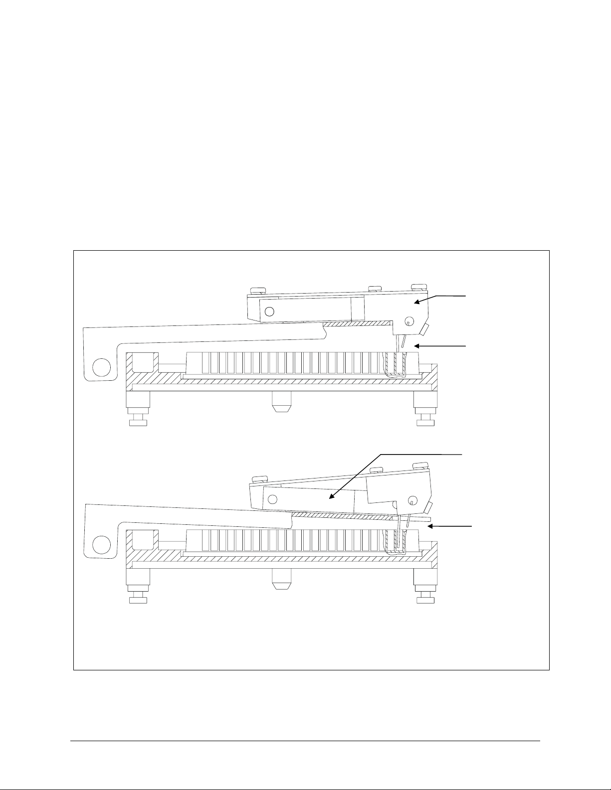
Patented Dual-Manifold Design
The patented Dual-Action™ 16-channel manifold has 16 sets of dispense and
aspirate tubes arranged in a fixed horizontal position relative to each other but
located in two separate manifolds (see
independently of each other on the vertical axis. This dual-manifold design
overcomes the problem of fitting both a dispense and an aspirate tube into the
much smaller 384-well at the same time, yet it allows for overfill washing of the
smaller 384 wells. The dispense tubes are held above the plate when the dispense
manifold reaches a mechanical stop, while the aspirate tubes are able to continue
descending into the wells.
Figure 1 below). The two manifolds move
Dispense
manifold
Figure 1: Patented Design of the 16-Channel Manifold
Tubes are
positioned
for overfill
washing
Aspirate
manifold
Tubes are
positioned
BioTek Instruments, Inc.
Page 27

Carrier Variations
The carrier is the washer component that transports microplates and positions the
wells underneath the manifold tubes. There are three possible carrier types, and their
usage depends on the manifold type installed and the microplate type being used:
• Microplate carrier that supports 8-, 8s-, and 12-channel manifolds and
solid-bottom plates.
• Microplate carrier that supports 16-, 8-, and 8s-channel manifolds and
solid-bottom plates.
• “Aspiration carrier” that supports 8- and 8s-channel manifolds and 96-well
filter-bottom plates. This carrier is used on ELx50/8FMW model only, and
aspirates fluid from below
through the filters at the bottom of the wells.
The basecode software onboard the ELx50/8FMW has been pre-configured to use
either the microplate carrier or the aspiration carrier. The aspirate-only program
parameters ASPIRATE TYPE and BOT ASPIRATE TIME only appear if the washer
model is the ELx50/8FMW, and the manifold is configured as either 8- or 8s-channel.
ELx50 Washer Variations | 5
the microplates, so that fluid is drawn down
Software Variations
The ELx50™ washer is operated by onboard software, controllable through the
washer’s keypad. This onboard software, referred to as the “basecode,” has an
identifying
Your washer is installed with one of three possible ELx50 basecode part numbers:
4070230, 4070261, or 4070201. Each part number in turn has an identifying
number.
be asked for the part number and version of the basecode currently residing on your
washer. See
information from the washer.
The
4070230 basecode supports:
• Compatibility with the 8-, 8s-, 12, and 16-channel manifolds. The 16-channel
• An easy to use, menu-driven interface.
• Ability to create Wash, Prime, Dispense, Aspirate, Soak, and Link programs for
• Storage of up to 75 washer programs.
• User-definable washer program names, for rapid recall at program run time.
part number.
If you need to contact BioTek Instruments for technical assistance, you will
Product Support & Service, page 12, for instructions for retrieving this
manifold supports both 96- and 384-well plate washing.
automated microplate washing.
version
• Configurable program parameters such as variable soaking, multispeed
shaking, bottom washing, and crosswise aspiration.
• Pre-defined washer programs that can be copied and used as the basis for new
programs.
ELx50 Operator's Manual
Page 28

6 | Chapter 1: Introduction
• Pre-defined maintenance programs, including AutoPrime, used to keep the
manifold tubes moist and free from clogging.
• Support for the following languages: English, French, German, Italian, and
Spanish.
Note: Contact BioTek for information on changing to a different
language.
• Compatibility with the ELx50/8FMW washer’s aspiration carrier, for bottom
aspiration of 96-well filter-bottom plates. Note: The 16-channel manifold
cannot be used with the aspiration carrier.
• Compatibility with the Liquid Level Alert™ option.
4070261 basecode supports the above features, but it is not compatible with the
The
Liquid Level Alert option and does not support the 16-channel manifold with the
ELx50/8FMW washer’s aspiration carrier.
The
4070201 basecode is not compatible with the 16-channel manifold, the Liquid
Level Alert option, or the ELx50/8FMW washer’s bottom aspiration carrier. This
basecode does not provide the ability to create Soak or Link programs.
BioTek Instruments, Inc.
Page 29

Hardware Features
• 2-line x 24-character LCD display.
• Membrane keypad with 25 alphanumeric keys.
• Washes:
96-well microplates with 0.355” / 9 mm well centers
384-well microplates with 0.177” / 4.5 mm well centers (washer
model-dependent)
96-well filter-bottom microplates (ELx50™/8FMW model only)
1 x 8 or 1 x 12 microwell strips
• Crosswise aspiration for optimizing washing performance.
• External 24-volt power supply.
• One serial RS-232 COM port (25-pin male connector).
Hardware Features | 7
• Supply and waste systems appropriate for the model/purchased options.
• Internal positive displacement pump provides controllable flow rates and volumes
to make washing cellular assays and immunoassays equally convenient. Settings
are adjustable via the onboard software, for low to high velocity dispensing.
• Internal vacuum pump aspirates liquid from the microwells into the waste
collection vacuum vessel.
• Stepper motors provide accurate and repeatable carrier and manifold positioning.
• Accommodates 1 x 8, 1 x 12, or 1 x 16 manifolds. See
Variations
for more information.
Appendix B, ELx50 Manifold
• Flat, round and ‘V’ bottomed strips and plates are washed.
• Carrier and manifold are easily removed for cleaning.
• Priming/soaking trough built into the carrier.
• Five shaking speeds for more intense washing.
• Programmable aspiration depth: Ensures that the tubes do not touch the well
bottom, allowing the handling of sensitive cell assays.
• ELx50/8FMW model: one vent port (0.047” in diameter) on the aspiration carrier
and two selectable vent plugs (with 0.032” and 0.020” diameter holes) for varying
the amount of vacuum used with the aspiration carrier.
• Mist shield protects the microplate from contaminants.
ELx50 Operator's Manual
Page 30

8 | Chapter 1: Introduction
Accessories Included
• 24 VDC power supply (PN 61062)
• Power cord (part number varies according to country of use)
• 8-, 8s-, 12-, or 16-channel manifold
• Microplate carrier (specific to manifold type)
• Aspiration carrier (ELx50™/8FMW model only) with two vent plugs:
One plug with 0.032” diameter hole (PN 4072100)
One plug with 0.020” diameter hole (PN 4072099)
• Mist shield (PN 4070517)
• Two 2-liter supply bottles (three with “V” version washers) (PN 4070515)
• One 2-liter waste bottle (PN 48140)
• Waste tubing set:
All models except ELx50/8FMW (PN 4070511)
ELx50/8FMW model only (PN 4073002)
• Supply tubing set (PN 4070510)
• Optional in-line vacuum filter (PN 48146)
• Optional vacuum pump muffler (PN 4073009) for ELx50 washers that are
equipped with the new vacuum pump (washers manufactured after January 2008)
• Stylus maintenance kit (PN 4070523)
• Operator’s Manual (PN 4071000)
• Packing instructions (PN 4071015)
• Set of shipping materials (PN 4073001)
• Shipping document (PN 94075) that includes a Warranty Statement and Certificate
of Compliance and Calibration
• Declaration of Conformity (PN 4071006 for clinical models or PN 4071034 for
non-clinical models)
Part numbers are subject to change over time. Please contact BioTek
Customer Care if you have any questions.
BioTek Instruments, Inc.
Page 31

Optional Accessories
• 8-channel manifold (PN 4070512)
• 8s-channel manifold (PN 4070519)
• 12-channel manifold (PN 4070513)
• 16-channel manifold (PN 4070527)
• Liquid Level Alert™ option:
PN 4070035, for non-“V” version washers: Liquid Level Alert select box with
2-liter supply bottle (1) and 2-liter waste bottle (1), with sensors
PN 4070036, for “V” version washers: Liquid Level Alert select box with
2-liter supply bottles (3) and 2-liter waste bottle (1), with sensors
• Spare vent plugs for aspiration carrier (ELx50™/8FMW model):
One plug with 0.032” diameter hole (PN 4072100)
Optional Accessories | 9
One plug with 0.020” diameter hole (PN 4072099)
• Millipore 96-well filter bottom microplates:
0.45 µm filter pore size (Millipore PN MSHVN4550)
1.2 µm filter pore size (Millipore PN’s MSBVN1B50 or MSBVN1210)
• RS-232 serial cable (PN 75053)
• In-line vacuum filter replacement (PN 48146)
• BioTek blue test dye solution (PN 7773001) and wetting agent solution
(PN 7773002) for liquid testing
• Installation-Operational-Performance Qualification (IQ-OQ-PQ) package
(PN 4070530)
• ELx50 Service Manual (PN 4071008)
Part numbers are subject to change over time. Please contact BioTek
Customer Care if you have any questions.
ELx50 Operator's Manual
Page 32

10 | Chapter 1: Introduction
Specifications
Microplates
• Microplates: 96-well, 384-well solid-bottom plates and
96-well filter-bottom plates, 0.45 µm to
• Microstrips: 1 x 8, 1 x 12
• Microwells: Flat, round, or “V” bottom
384-well support is available with the 16-channel manifold only.
Electrical
1.2 µm filter pore size (ELx50™/8FMW)
• Voltage range: 100 to 250 V~, 50 to 60 Hz
• Power Consumption: 40 W
Physical
• Dimensions: 16 in. D x 14 in. W x 6.5 in. H
• Weight: ≤ 20 lbs. (8.9 kg) all models except ELx50/8FMW;
Environmental
• Operating conditions: 15° - 40°C (59° - 104°F)
• Relative humidity: 10% - 85% (non-condensing)
Hardware
• Manifold type: 8-, 8s-, 12-, or 16-channel manifold,
depending on washer model
(40.6 cm x 35.6 cm x 16.5 cm)
≥ 22 lbs. (9 kg) ELx50/8FMW model
• Waste bottle volume: 2 liters
• Supply bottle volume: 2 liters
• User interface (LCD): 2 x 24 LCD display; 25 alphanumeric soft keys
BioTek Instruments, Inc.
Page 33

Performance Specifications
Residual Volume (Evacuation Efficiency)
96-Well Performance: Average residual of < 2.0 µl per well after a 3-cycle wash, when
dispensing 300 µl per well, into a minimum of 4 strips, using a
solution of deionized water with 0.1% Tween
buffer solution. The aspirate height adjustment should be
optimized for the plate prior to testing.
Specifications | 11
®
20 or equivalent
384-Well Performance:
(16-channel only)
Average residual of < 4.0 µl per well after a 1-cycle wash, when
dispensing 100 µl per well, into a minimum of 4 strips, using a
solution of deionized water with 0.1% Tween 20 or equivalent
buffer solution. The aspirate height adjustment should be
optimized for the plate prior to testing.
Residual Volume specifications do not apply to the ELx50™/8FMW washer when using
the aspiration carrier for filter-bottom plates. Residual Volume specifications are only
applicable when using the microplate carrier for solid-bottom plates.
Dispense Precision
96-Well Performance:
< 3.0% CV when measured over 6 strips from an 8- or
8s-channel manifold, or 4 strips from a 12- channel manifold,
dispensing 300 µl per well of deionized water with 0.1% Tween
20 and colored dye at a rate of 300 µl per well per second.
384-Well Performance:
(16-channel only)
< 4.0% CV when measured over 6 strips from a 16-channel
manifold, dispensing 100 µl per well of deionized water with
0.1% Tween 20 and colored dye.
Processing Speed
96-Well Performance < 130 seconds for 12 strips (3 cycles, 300 µl/well, no soak)
384-Well Performance
(16-channel only )
ELx50 Operator's Manual
< 260 seconds for 24 strips (3 cycles, 100 µl/well, no soak)
Page 34

12 | Chapter 1: Introduction
Product Support & Service
All of BioTek’s products are backed by a superior support staff. If your instrument ever
fails to function perfectly, if you have questions about how to use or maintain it, or if you
need to send the instrument to BioTek for service or repair, please contact our Technical
Assistance Center (TAC).
Contacting the Technical Assistance Center
Our Technical Assistance Center is open from 8:30 AM to 5:30 PM (EST), Monday
through Friday, excluding standard U.S. holidays. You can send a fax or an e-mail any
time.
Phone: 800-242-4685 (in the U.S.) or 802-655-4740 (outside the U.S.)
Fax: 802-655-3399
E-Mail: tac@biotek.com
Please be prepared to provide the following information:
• Your name and company information
• A daytime phone or fax number, and/or an e-mail address
• The product name, model, and serial number
• The software part number and basecode version (available via the washer’s
main menu by selecting
UTIL TESTS CHKSUM)
• For troubleshooting assistance or instruments needing repair: the specific
steps that produce your problem, and any error codes displayed (see also
Appendix A, Error Codes).
Returning Instruments for Service/Repair
If you need to return an instrument to BioTek for service or repair, please contact the
TAC for a Return Materials Authorization (RMA) number before shipping the
instrument. Repackage the instrument properly (see
the RMA number on the shipping box, and ship to this address:
BioTek Instruments, Inc.
Technical Assistance Center
100 Tigan Street
Highland Park
Winooski, Vermont 05404 USA
Chapter 2, Installation), write
BioTek Instruments, Inc.
Page 35

Chapter 2
Installation
This chapter includes instructions for unpacking and setting up the
ELx50™ Microplate Strip Washer, installing the washer's
components, and repackaging the instrument for shipment.
Unpacking and Inspecting the Instrument ...................................14
Setting Up the ELx50 ...............................................................20
Operating Environment ........................................................20
Installing the Carrier and Manifold .........................................20
Connecting the Tubes and Bottles..........................................25
Attaching the Mist Shield......................................................35
Connecting the Power Supply and Cord ..................................36
Serial Port for Communication With Other Devices ...................36
Verifying Performance ..............................................................37
Repackaging and Shipping ........................................................38
Before Repackaging the Instrument .......................................38
Repackaging the ELx50 and Its Accessories.............................39
Page 36

14 | Chapter 2: Installation
Unpacking and Inspecting the Instrument
Important! Save all packaging materials. If the washer is
The ELx50™ washer and its accessories are securely packaged inside custom-designed
shipping materials. This packaging should protect the instrument from damage during
shipping. Inspect the shipping box, packaging, instrument, and accessories for signs of
damage.
shipped to the factory for repair or replacement, it must be carefully
repackaged, according to the instructions on pp. 38 to 49, using the
original packing materials. Using other forms of commercially
available packing materials, or failure to follow the repackaging
instructions may void your warranty. If the original packing
materials have been damaged, contact BioTek and ask for part
number 4073001.
If the washer is damaged: Notify the carrier and your manufacturer's representative.
Keep the shipping cartons and packing material for the carrier's inspection. The
manufacturer will arrange for repair or replacement of your instrument immediately,
before the shipping-related claim is settled.
Refer to the unpacking instructions and
removing the instrument and its accessories from the shipping container.
See
Repackaging and Shipping at the end of this chapter for complete shipping
instructions.
Figures 2 through 6 on the following pages when
BioTek Instruments, Inc.
Page 37

Unpacking and Inspecting the Instrument | 15
Unpacking the 16-Channel Manifold, Mist Shield, and Bottles
1. Carefully open the outer shipping container and lift the top packing container
and shipping tray that contain the accessories out of the container.
2. Remove the 16-channel manifold, mist shield, and waste and supply bottles,
and then set aside their shipping materials.
3. Refer to Figure 3 on the following page for unpacking the shipping tray for the
8-, 8s-, or 12-channel manifold, microplate carrier, power supply, tubing,
in-line filter, and other accessories.
The bottles include two 2-liter supply bottles and one 2-liter waste
bottle. The “V” version of the ELx50™ (washers equipped with the
optional valve module) will include three 2-liter supply bottles.
Figure 2: Unpacking the 16-Channel Manifold. Mist Shield, and Bottles
ELx50 Operator's Manual
Page 38

16 | Chapter 2: Installation
Unpacking the 8-, 8s-, or 12-Channel Manifold, Microplate Carrier, Power Supply, Tubing, In-Line Filter, and Optional Pump Muffler
1. Carefully open the shipping tray for the 8-, 8s-, or 12-channel manifold,
microplate carrier, power supply and power cord, tubing, in-line vacuum filter,
optional vacuum pump muffler, manual, and Declaration of Conformity or
other documents.
2. Remove the accessories listed above and set aside the shipping materials.
Figure 3: Unpacking the 8-, 8s-, or 12-Channel Manifold, Microplate Carrier, Power Supply,
Tubing, In-Line Vacuum Filter, and Optional Vacuum Pump Muffler
BioTek Instruments, Inc.
Page 39

Unpacking and Inspecting the Instrument | 17
Unpacking the Inner Shipping Container and Foam Corner Blocks
1. Lift the inner shipping container with the eight foam corner blocks out of the
outer shipping container as shown in the figure below and place it upon a level
surface. This package contains the washer.
an aspiration carrier and two vent plugs.
2. Remove and set aside the foam corner blocks.
3. Carefully open the inner shipping container, using a blunt tool.
ELx50™/8FMW washers include
Figure 4: Unpacking the Inner Shipping Container and Foam Corner Blocks
ELx50 Operator's Manual
Page 40

18 | Chapter 2: Installation
Unpacking the Aspiration Carrier (ELx50/8FMW models only)
1. Remove the aspiration carrier from its storage compartment in the inner
shipping container.
2. Remove and set aside any bubble wrap, plastic bag, or other shipping
materials.
Figure 5: Unpacking the Aspiration Carrier (ELx50™/8FMW)
BioTek Instruments, Inc.
Page 41

Unpacking the ELx50™ Washer
1. Lift insert #2, then insert #1 out of the inner shipping container (as shown
below).
2. Carefully lift the washer out of the inner shipping container and place it on a
level surface.
3. Remove the washer from the plastic bag.
4. Slide the foam shipping block out from underneath the manifold mounting
bracket.
5. Store the inner shipping container and all shipping materials (including those
noted on the previous pages) in the outer shipping container.
Unpacking and Inspecting the Instrument | 19
Figure 6: Unpacking the ELx50 Washer
ELx50 Operator's Manual
Page 42

20 | Chapter 2: Installation
Setting Up the ELx50
Important! Avoid excessive humidity. Condensation
Operating Environment
The ELx50™ washer is sensitive to extreme environmental conditions. For optimal
operation, install the washer
directly on the sensitive electronic circuits can cause the
instrument to fail internal self checks.
The manifold dispense tubes have a protective Teflon collar
at the tip. This is to prevent dripping. Do not remove
these coverings!
• on a level surface,
• in an area where ambient temperatures between 15°C (59°F) and 40°C
(104°F) can be maintained, and
• away from excess humidity.
Specifications in Chapter 1, Introduction, for a list of environmental
See
specifications.
Installing the Carrier and Manifold
All ELx50 washers have a microplate carrier that is specific to their manifold type.
See
ELx50 Washer Variations in Chapter 1, Introduction, for information on the
various manifold and carrier types.
Refer to
ELx50/8FMW: Refer to
Microplate Carrier
Figures 7 and 8 when installing the microplate carrier and manifold.
Figures 9 and 10 when installing the aspiration carrier.
1. Hold the microplate carrier over the rail so that the priming/soaking
trough is closest to the rear of the washer.
2. Line up the pin on the underside of the carrier with the slot on the carrier
transport.
3. Snap the two carrier rail guides onto the carrier transport rail. The pin
should sit in the slot.
BioTek Instruments, Inc.
Page 43

Setting Up the ELx50 | 21
8-, 8s-, or 12-Channel Manifold
1. Orient the manifold so that the aspirate/dispense tubes are pointed down,
and the fittings for the supply and waste tubing are pointed toward the
back of the washer.
2. Slide the manifold gently down over the two support pins on the manifold
mounting bracket that are closest to the front of the washer.
3. Insert the thumbscrews (2). Do not overtighten.
Figure 7: Installing the Microplate Carrier and 8-, 8s, or 12-Channel Manifold
ELx50 Operator's Manual
Page 44

22 | Chapter 2: Installation
16-Channel Manifold
1. Orient the manifold so that the aspirate/dispense tubes are pointed down,
and the fittings for the supply and waste tubing are pointed toward the
back of the washer.
2. Slide the manifold gently down over the three support pins on the
manifold mounting bracket.
3. Insert the thumbscrews (3). Do not overtighten.
Figure 8: Installing the Microplate Carrier and 16-Channel Manifold
BioTek Instruments, Inc.
Page 45

Setting Up the ELx50 | 23
Aspiration Carrier (ELx50™/8FMW)
For bottom aspiration using the aspiration carrier, the 8- or 8s-
channel manifold must be installed. The aspiration carrier does not
support the 12-channel manifold.
1. Hold the aspiration carrier over the rail so that the priming/soaking trough
is closest to the rear of the washer.
2. Line up the pin on the underside of the carrier with the slot on the carrier
transport.
3. Snap the two carrier rail guides onto the carrier transport rail. The pin
should sit in the slot.
4. Follow the instructions on the next page for setting the vacuum levels using
the vent port and vent plugs.
Figure 9: Installing the Aspiration Carrier (ELx50/8FMW model)
ELx50 Operator's Manual
Page 46

24 | Chapter 2: Installation
5. Slide the latch on the plate clamp to the right to open the clamp, whenever
inserting or removing a plate.
6. Use the vent port (labeled “C”) on the carrier and the two vent plugs
(located in storage slots “A” and “B”) to vary the vacuum levels. The vent
port is a 0.047” diameter hole, which is equal to approximately -64 mmHg.
The gray vent plug contains a 0.032”diameter hole, which is equal to
approximately -116 mmHg. The black vent plug contains a 0.020” diameter
hole, which is equal to approximately -240 mmHg.
For a
For a
low vacuum level, leave the vent port on the carrier open.
medium vacuum level, insert the gray vent plug into the vent
port.
For a
The approximate vacuum levels listed above (-64, -116, and
-240 mmHg) are “typical” only, and may vary, depending upon
factors such as relative humidity, barometric pressure, and
mechanical tolerances.
high vacuum level, insert the black vent plug into the vent port.
Figure 10: Close-Up View of Aspiration Carrier Vent Port and Vent Plugs
BioTek Instruments, Inc.
Page 47

Connecting the Tubes and Bottles
Caution. The washer manifold, the vacuum port, and the
supply bottles have Luer fittings. Finger-tighten only!!
Important! Review Figures 11 through 17 on the following
For optimal operation of the ELx50™ washer, all tubing, cables, and fittings for the
waste and supply systems must be properly connected. The figures on the following
pages illustrate the rear panel of the instrument and the locations of the ports and
connections for the waste and supply systems.
Liquid Level Alert™ option: If you purchased the Liquid Level Alert option, its
components are shipped in a separate box. Install the waste and supply bottle(s) as
described on the following pages, and then install the select box and connect the cables
as described on page 34.
pages, as well as the diagram on the back of the washer.
Identify the different tubes and bottles that came with your
washer.
Setting Up the ELx50 | 25
• For PN 4070035 (non-“V” version washers), components include a select box,
one 2-liter supply bottle, and one 2-liter waste bottle.
• For PN 4070036 (“V” version washers), components include a select box,
three 2-liter supply bottles, and one 2-liter waste bottle.
Vacuum Pump Muffler: An optional vacuum pump muffler (PN 4073009) is
provided with ELx50 washers that are equipped with the new vacuum pump (washers
manufactured after January 2008). If you wish to use the muffler, attach the female luer
end of the muffler to the vacuum pump output/exhaust port on the rear panel of the
washer. See
vacuum pump muffler.
Before Connecting the Tubes and Bottles
1. Rinse all bottles with deionized or distilled water before using. This
2. Place the supply and waste bottles on the same horizontal plane as the
Figure 11b and Figure 12b on the following pages for illustrations of the
rinsing eliminates particles that may have entered during packing or
unpacking.
washer. This ensures optimum pump performance.
ELx50 Operator's Manual
Page 48

26 | Chapter 2: Installation
Figure 11a: Washer Rear Panel (all models except ELx50™/8FMW)
Figure 11b: Attaching the Vacuum Pump Muffler (all models except ELx50/8FMW)
BioTek Instruments, Inc.
Page 49

Setting Up the ELx50 | 27
Figure 12a: Washer Rear Panel (ELx50™/8FMW model)
Figure 12b: Attaching the Vacuum Pump Muffler (ELx50/8FMW model)
ELx50 Operator's Manual
Page 50

28 | Chapter 2: Installation
Waste System
All models except the ELx50™/8FMW: Follow steps 1 through 4 below for
connecting the waste tubing and bottle. Refer to
illustration of the rear panel of the washer, and to
illustration of the waste tubing connections.
1. Attach the paired (Y-shaped) waste tubing to the two waste ports on the
back of the washer manifold.
2. Remove the waste bottle cover and replace it with the stopper from the
waste tubing set.
3. To install the optional* in-line vacuum filter, cut the tubing from the waste
bottle to the vacuum pump output port in half and attach both cut ends to
the vacuum filter ports.
4. Attach the free end of the tubing from the waste bottle to the vacuum port
for waste fluid on the back of the washer.
Figure 11 on page 26 for an
Figure 13 on page 29 for an
Finger-tighten only!
Finger-tighten only!
ELx50/8FMW model (with aspiration carrier installed):
through 7 below for connecting the waste tubing and bottle. Refer to
the previous page for an illustration of the rear panel of the washer, and to
on page 30 for an illustration of the waste tubing connections.
14
1. Attach the paired (Y-shaped) waste tubing to the two waste ports on the
back of the washer manifold.
2. Attach the free end of the waste tubing from the manifold to the top
Finger-tighten only!
Follow steps 1
Figure 12 on
Figure
aspiration port (“TOP ASP”) on the back of the washer.
Finger-tighten only!
3. Remove the waste bottle cover and replace it with the stopper from the
waste tubing set.
4. Attach one tube from the waste bottle to the vacuum pump output port on
the back of the washer.
5. To install the optional* in-line vacuum filter, cut the tubing from the waste
bottle to the vacuum pump output port in half and attach both cut ends to
the vacuum filter ports.
6. Attach the free end of the tubing from the waste bottle to the vacuum port
for waste fluid on the back of the washer.
7. Attach the waste tubing from the aspiration carrier to the bottom aspiration
port (“BOT ASP”) on the back of the washer.
Finger-tighten only!
Finger-tighten only!
The in-line vacuum filter is “optional” in the sense that the washer will func tion
without it. It is strongly recommended that you install this filter, however,
because (1) the filter prevents waste material aerosols from being released into
the air, and (2) the filter serves as a temporary fluid barrier in the event that the
waste bottle is allowed to overfill. (The replacement PN for the filter is 48146.)
BioTek Instruments, Inc.
Page 51

Setting Up the ELx50 | 29
Figure 13: Waste Tubing Connections (all models except the ELx50™/8FMW)
Note: The washer's top shroud is removed from this illustration for
clarity only. While it is acceptable to remove the mist shield, do not
attempt to remove the shroud protecting the washer's components.
ELx50 Operator's Manual
Page 52

30 | Chapter 2: Installation
Figure 14: Waste Tubing Connections
(ELx50™/8FMW model with Aspiration Carrier installed)
BioTek Instruments, Inc.
Page 53

Supply System
Refer to Figure 15 for the following instructions.
1. Two check valves are supplied; note the flow direction arrows. Connect the
check valves to the syringe pump top and bottom ports. Compare the flow
direction arrows with those shown in
ELx50™/8FMW) or
2. Two supply tubes are provided, one short, one long. Connect one end of
the short tube
to the manifold. Connect the other end to the check valve
that is connected to the syringe pump top port.
3. Washers without the multiple valve tubing option: Connect one end of
the long tube
to the supply bottle and the other end to the check valve
connected to the syringe pump bottom port.
4. Washers with the multiple valve tubing option: The long tube is longer
than necessary and should be cut to approximately 5 inches when installing
to minimize prime volume. Connect one end of the 5-inch tube to the valve
output port on the rear panel of the washer and the other end to the check
valve connected to the syringe pump bottom port.
Figure 12 (ELx50/8FMW model).
Setting Up the ELx50 | 31
Figure 11 (all models except the
Attach the three tubes from supply bottles A, B, and C to valve ports A, B,
and C on the back of the washer.
Note: The ELx50/8FMW model does not support the multiple valve
tubing option.
ELx50 Operator's Manual
Page 54

32 | Chapter 2: Installation
Figure 15a: Supply Tubing Connections (front view)
Figure 15b: Supply Tubing Connections (view of connections on rear panel)
Note: The washer's top shroud is removed from this illustration for
clarity only. While it is acceptable to remove the mist shield, do not
attempt to remove the shroud protecting the washer's components.
BioTek Instruments, Inc.
Page 55

Setting Up the ELx50 | 33
Figure 16: Washer with Multiple Valve Tubing Connections
(“V” versions of the ELx50™)
ELx50 Operator's Manual
Page 56

34 | Chapter 2: Installation
Liquid Level Alert™ Option
If you have not already done so, connect the waste and supply bottles as described
on the previous pages.
1. The Liquid Level Alert select box has four ports, labeled A, B, and C, for
the supply bottle(s), and WASTE.
• For washers with the Valve option, connect the supply bottle cables to
the appropriate ports in the select box. If a port is left empty, insert one
of the supplied “shorting plugs” (all ports must be filled).
• For washers without the Valve option, connect the supply bottle cable to
port A and then insert the supplied shorting plugs into ports B and C.
• For all washers, connect the waste bottle cable to the WASTE port.
2. Connect the select box to the washer via the LIQUID ALERT port on the
back of the washer.
Connects to washer
Shorting plugs
Liquid
Alert port
Supply (A)
Waste
Figure 17: Liquid Level Alert select box (top), and cable connections
BioTek Instruments, Inc.
Page 57

Final Check
1. Verify that the tubing was not crimped during installation.
2. Make sure that the fluid supply and the waste output tubes are attached to
the appropriate manifold ports. If the mounted manifold tilts forward or
backward, make sure that the tubing to the manifold is not being pulled
tight or off to the side.
Attaching the Mist Shield
Refer to Figure 18 below for the following instructions.
1. Insert the two thumbscrews into the slots on the washer’s left side. Do not
tighten completely.
2. Hold the mist shield parallel to the washer’s left side, with the door toward the
front of the washer. See below.
3. Slide the mist shield down so that the two slots fit over the thumbscrew shafts.
Setting Up the ELx50 | 35
4. Insert the two pins into the slots on the washer’s top left side.
5. Tighten the thumbscrews.
Figure 18: Attaching the Mist Shield
ELx50 Operator's Manual
Page 58

36 | Chapter 2: Installation
Connecting the Power Supply and Cord
Warning! Power Rating. The ELx50™ power supply
must be connected to a power receptacle that provides
voltage and current within the specified rating for the
system. Use of an incompatible power receptacle may
produce electrical shock and fire hazards.
Warning! Electrical Grounding. Never use a two-
prong plug adapter to connect primary power to the ELx50
power supply. Use of a two-prong adapter disconnects the
utility ground, creating a severe shock hazard. Always
connect the power cord directly to a three-prong receptacle
with a functional ground.
The ELx50™ Washer uses an external 24-volt power supply. The power supply
automatically adjusts for input voltage in the range of 100 - 250 V~.
1. Plug the power supply’s plug into the washer’s rear panel. See Figure 11
(all models except the ELx50/8FMW) or
2. Insert the power cord into the power supply and into an appropriate wall
outlet.
Serial Port for Communication With Other Devices
The ELx50 has a 25-pin serial (RS-232) port located on the rear panel of the instrument
(see
Figure 11 or Figure 12). The serial port allows the washer to receive data from a
computer for purposes of factory or dealer service.
Figure 12 (ELx50/8FMW model).
BioTek Instruments, Inc.
Page 59

Verifying Performance | 37
Verifying Performance
Before using the ELx50™ washer for the first time, verify that it is operating properly by
turning the washer on. The washer will automatically perform a system Self-Test to check
the manifold, microplate carrier, vacuum pump and syringe pump positioning and
operation. You can also choose to run this test from the washer’s front panel, by selecting
UTIL > TESTS > SLFCHK.
Once the self test has completed successfully, the washer is ready for use. For more
information regarding verification of the washer’s performance, see
Maintenance and Performance Verification (IQ/OQ/PQ)
If the test passes, the Main Menu will be displayed. If the test fails, the washer will
beep repeatedly and the display will show an error code. If this happens, note the error
code and then press the
Error Codes, to determine its cause. If the problem is something you can fix, turn off the
washer, fix the problem, and then turn the washer back on. If the cause is not something
you can fix, contact BioTek’s Technical Assistance Center.
Stop key on the keypad to stop the beeping. Refer to Appendix A,
Chapter 4,
.
Chapter 4, Maintenance and Performance Verification (IQ/OQ/PQ) provides
recommended Installation and Operational Qualification procedures to be performed after
the instrument is installed and set up as described in this chapter, and before the
instrument is used in a laboratory environment.
The successful completion of the Installation Qualification confirms that the washer and its
components have been supplied as ordered and ensures that they are assembled and
configured properly for your lab environment. The successful completion of the
Operational Qualification confirms that the washer is operating according to specification.
Note: An instrument qualification package (PN 4070530) for the
ELx50 is available for purchase from BioTek. The package contains
thorough procedures for performing Installation Qualification,
Operational Qualification and Performance Qualification (IQ/OQ/PQ)
and preventive maintenance (PM). Extensive Checklists and Logbooks
are included for recording results. Contact your local dealer for more
information.
Important! Before operating this washer, review the
General Usage Guidelines in Chapter 3. These
guidelines include necessary steps to perform before running
any program, information on performing periodic
maintenance, and points to consider when creating or editing
washer programs.
ELx50 Operator's Manual
Page 60

38 | Chapter 2: Installation
Repackaging and Shipping
If you need to ship the ELx50™ Washer to BioTek for service or repair, be sure to use the
original packing. Other forms of commercially available packing are not recommended
and can void the warranty.
If the original packing materials have been damaged or lost, contact BioTek for
replacement packing (see Technical Assistance
The instrument’s packaging design is subject to change over time. If
the instructions in this section do not appear to apply to the packaging
materials you are using, please contact BioTek’s Technical Assistance
Center for guidance.
Before Repackaging the Instrument
Warning! If the washer has been exposed to potentially
hazardous material, decontaminate it to minimize the risk to
all who come in contact with the washer during shipping,
handling and servicing.
in Chapter 1 for contact information).
Decontamination prior to shipping is required by the U.S.
Department of Transportation regulations.
Important! Perform the following steps in the order
1. Decontaminate the washer and its accessories as necessary. Refer to the
Decontamination procedure in Chapter 4 for complete instructions.
2. Obtain a Return Materials Authorization (RMA) number from BioTek’s
Technical Assistance Center through BioTek’s website, fax, or e-mail
address listed in
3. When obtaining the RMA, explain whether the washer requires calibration,
cleaning, periodic maintenance, warranty work, and/or repair. Make a note
of any error messages displayed and their frequency.
4. Provide BioTek with the name and contact information of a person who
may be contacted if questions arise.
5. Mark the RMA number on the outside of the shipping box.
6. Insure the instrument for full value before shipping to BioTek.
presented before repackaging the washer for shipment.
Chapter 1.
BioTek Instruments, Inc.
Page 61

Repackaging the ELx50 and Its Accessories
Refer to Figures 19 through 29 below and on the following pages when
repackaging the ELx50.
Removing the Mist Shield
1. Turn the washer off and disconnect the power supply cord and all waste
and supply tubing (and, if applicable, the optional valve tubing) from the
washer.
2. Remove the two mist shield thumbscrews.
3. Remove the mist shield and place it into a plastic bag (not shown).
4. Reinstall the two mist shield thumbscrews into their slots on the washer.
Repackaging and Shipping | 39
Figure 19: Removing the Mist Shield
ELx50 Operator's Manual
Page 62

40 | Chapter 2: Installation
Removing the Manifold and Microplate Carrier
1. Remove the thumbscrews from the manifold.
2. For all models of the manifold: Lift the manifold carefully from the
support pins on the manifold mounting bracket.
3. For the 8-, 8s-, or 12-channel manifolds only: Screw the two
thumbscrews back into their support pins on the manifold mounting
bracket.
4. Pack the manifold as instructed on the following two pages.
5. Remove the microplate carrier and place it into a plastic ziplock bag.
Figure 20: Removing the Manifold and Microplate Carrier
BioTek Instruments, Inc.
Page 63

Removing the Aspiration Carrier (ELx50™/8FMW)
1. Disconnect the tubing from the back of the aspiration carrier.
2. Lift the carrier off the carrier transport rail.
3. Ensure that the two vent plugs are inserted in the “A” and “B” storage slots
in the front panel of the carrier, for shipping.
4. Place the carrier into a plastic ziplock bag.
Repackaging and Shipping | 41
Figure 21: Removing the Aspiration Carrier (ELx50/8FMW)
ELx50 Operator's Manual
Page 64

42 | Chapter 2: Installation
Packing the 8-, 8s-, or 12-Channel Manifold in Its Container
1. Place the manifold into the foam shipping container as shown.
2. Wrap a large rubber band around the shipping block.
3. Place the shipping block into a plastic ziplock bag.
Figure 22: Packing the 8-, 8s-, or 12-Channel Manifold
BioTek Instruments, Inc.
Page 65

Repackaging and Shipping | 43
Packing the 16-Channel Manifold in Its Container
1. Place the three thumbscrews into a small ziplock bag. Insert the bag into
the hole in the bottom of the foam shipping container for the 16-channel
manifold.
2. Place the manifold into a plastic bag.
3. Insert the bag into the container.
Figure 23: Packing the 16-Channel Manifold in Its Container
ELx50 Operator's Manual
Page 66

44 | Chapter 2: Installation
Rotating the Cam
1. Ensure that the mist shield, manifold, and carrier have been removed as
instructed on the previous pages.
2. Rotate the cam until it is in the downward position, as shown below.
Figure 24: Rotating the Cam
BioTek Instruments, Inc.
Page 67

Repackaging and Shipping | 45
Placing the Washer into the Inner Shipping Container
1. Ensure that the cam is in the down position as shown on the previous page.
2. Align the groove in the foam shipping block to the manifold mounting
bracket and push the block onto the bracket.
3. Place the washer into a plastic bag.
4. Carefully lower the instrument into the inner shipping container, placing it
all the way forward into the box.
5. Place insert #1 into the shipping container, as shown below.
6. Slide the washer all the way back to insert #1.
7. Place insert #2 into the front of the shipping container, as shown below.
Figure 25: Placing the Washer into the Inner Shipping Container
ELx50 Operator's Manual
Page 68

46 | Chapter 2: Installation
Placing the Aspiration Carrier into the Inner Shipping Container
1. ELx50™/8FMW model only: Place the aspiration carrier in its
compartment as shown.
2. Close the inner shipping container.
Figure 26: Placing the Aspiration Carrier (ELx50/8FMW) into the Inner Shipping Container
BioTek Instruments, Inc.
Page 69

Packing the Inner Shipping Container
1. Place the eight foam corner blocks onto the inner container as shown.
2. Place the container into the outer shipping container.
Repackaging and Shipping | 47
Figure 27: Packing the Inner Shipping Container
ELx50 Operator's Manual
Page 70

48 | Chapter 2: Installation
Packing the 16-Channel Manifold and Mist Shield
1. Slide the 16-channel manifold underneath the mist shield as shown.
2. Insert the mist shield and manifold into the top packing container.
3. Place the container on top of the inner shipping box.
Figure 28: Packing the 16-Channel Manifold and Mist Shield
BioTek Instruments, Inc.
Page 71

Repackaging and Shipping | 49
Packing the 8-, 8s-, or 12-Channel Manifold, Microplate Carrier, and Power Supply
1. Place the 8-, 8s-, or 12-channel manifold, microplate carrier, and power
supply into the shipping tray as shown, then place into the outer shipping
container.
2. Close the top of the outer shipping box and tape it shut.
3. Write “RMA” and the RMA number in large, clear letters on the outside of
the shipping container and ship the instrument to the BioTek address
provided in the
Product Support & Service section of Chapter 1.
Figure 29: Packing the 8-, 8s-, and 12-Channel Manifold, Microplate Carrier, and Power Supply
ELx50 Operator's Manual
Page 72

50 | Chapter 2: Installation
BioTek Instruments, Inc.
Page 73

Chapter 3
Operation
This chapter includes instructions for operating the ELx50™
Microplate Strip Washer and its software.
ELx50 Front Panel....................................................................52
Keypad Description ..................................................................53
Entering Program Names ..........................................................54
System Startup .......................................................................54
Main Menu..............................................................................55
General Usage Guidelines .........................................................56
Wash .....................................................................................60
Prime.....................................................................................72
Dispense ................................................................................76
Aspiration...............................................................................79
Soak......................................................................................83
Linking Programs.....................................................................86
Utility.....................................................................................89
ELx50 Microplate Strip Washer Menu Maps ..................................92
Page 74

52 | Chapter 3: Operation
ELx50 Front Panel
The front panel on the ELx50™ Microplate Strip Washer features a 25-key keypad and
a 2 x 24-character LCD display as shown in
Figure 30 below.
LCD display
SoftKeys (4)
Alphanumeric
keys
BIO-TEK ELx50
RUN DEFINE MAINT UTIL
Figure 30: ELx50 Front Panel, With LCD and Keypad
Menu functions
(second line of
LCD display)
Special function keys
BioTek Instruments, Inc.
Page 75

Keypad Description
Keypad Description | 53
Main
Menu
Options
ENTER
Previous
Screen
CLEAR
The keypad has four
SoftKeys, one below each selectable menu
option. Press a SoftKey to choose a menu selection. For example, from
the Main Menu, press the leftmost SoftKey to select RUN, the rightmost
to select UTIL.
Exit the current screen and return to the
Main Menu. After defining a
washer program, press the Main Menu key, then press YES to save the
program.
To scroll through the different options within a program, press the
Options key or the Shift + Options key combination. Press the
ENTER key to select the current option.
Pressing
ENTER generally saves the current screen settings and
advances to the next screen in a series.
To move to a previous menu, press the
Press
CLEAR to delete an entry.
Previous Screen key.
START
STOP
◄
►
Press the ◄ (reverse) arrow to move the cursor to the left in the LCD
display.
Press the ► (forward) arrow to move the cursor to the right in the LCD
display.
To start running a washer program, press the
START key.
To stop running (abort) a washer program, press the
STOP key.
ELx50 Operator's Manual
Page 76

54 | Chapter 3: Operation
Entering Program Names
Each ELx50™ washer program requires the entry of a unique name, using up to 16
alphanumeric characters. To enter a program name via the washer keypad:
1. Press Shift + key A-H, or
2. Scroll through the alphabet with the Options key for A-Z.
3. Press Shift + Options to reverse direction.
4. Use the ► (forward) or ◄ (reverse) arrows to move the cursor within the
display.
5. Press the ENTER key to store the completed program name and continue.
If the program name already exists, the washer software will require you to enter a unique
name. This protects washer programs from inadvertently being overwritten.
The NAME display offers four symbols that can be used in a program name: dash (hyphen),
forward slash, colon, and underscore (see below). These symbols appear in the LCD as
SoftKey choices. To include a symbol within a program name, press its corresponding
SoftKey.
NAME: WASH 96
- / : _
System Startup
To turn on the ELx50™, press the on/off switch on the right side of the base. The ELx50
will perform a self-test, displaying the screens shown below until initialization is complete.
During this time, all keys are inactive.
If the self-test fails, the washer will “chirp” and display an error code. Press
the chirp. Refer to
interpret these codes. Contact BioTek Instrument’s Technical Assistance Center (see page
12), for further assistance with troubleshooting.
Chapter 5, Troubleshooting and Appendix A, Error Codes, to
POWERUP SEQUENCE V1.02
INITIALIZING. . .
(Instrument ID)
STOP to stop
SYSTEM SELF-TEST. . .
BioTek Instruments, Inc.
Page 77

Main Menu
Following successful power-up of the ELx50™, the Main Menu appears:
BIO-TEK ELx50
RUN DEFINE MAINT UTIL
The following options are available through the Main Menu. (See the Washer Menu
on pages 92 through 95for a complete listing of menu options.)
Maps
Main Menu | 55
BIO-TEK ELx50
RUN DEFINE MAINT UTIL
SELECT UTILITY:
TESTS SETUP AUTOPRIME
SELECT MAINT PROGRAM:
(*See options below.)
SELECT ACTION:
CREATE EDIT COPY DELETE
SELECT PROGRAM TYPE:
WASH PRIME DISP *MORE
SELECT PROGRAM TYPE:
ASPIR SOAK LINK *MORE
*Maintenance options include:
DECONTAMINATION, LONG_SHUTDOWN, OVERNIGHT_LOOP,
RINSE_AND_SOAK, and DAY_RINSE.
ELx50 Operator's Manual
Page 78

56 | Chapter 3: Operation
General Usage Guidelines
Important! Please review the General Usage Guidelines
When operating the washer, follow these guidelines to ensure optimal performance
and to prevent the problems described in the troubleshooting charts in
Troubleshooting.
before running any programs.
Vacuum Filter: It is strongly recommended that you install the
hydrophobic in-line vacuum filter before using the ELx50™.
See Connecting the Tubes and Bottles in Chapter 2 for
more information.
Chapter 5,
Before Running Any Program
• Fill the wash/rinse bottles with sufficient fluid. Make sure the supply tube is
in the liquid.
• The supply tube should extend to the bottom of the bottle and be
cut at the end (see drawing to the right) to ensure free flow of
liquid at the bottom of the supply bottle.
• Empty the waste bottle and firmly seat the waste bottle’s stopper. To ensure
that fluid does not back up into the vacuum pump during operation, never
allow the waste bottle to become more than three-quarters full.
• Check the external tubing connections for kinks and clogs.
• For washers with the aspiration carrier (ELx50/8FMW): when setting up the
tubing from the aspiration carrier to the port on the back of the washer, ensure
that there is sufficient room for the tubing.
Since the carrier moves in and out during a Dispense program, a clear tubing
flex path needs to be maintained so that carrier motion is not impeded.
Pushing the instrument up against a wall or against the vacuum/dispense
bottles can result in errors, because the carrier loses steps during movement.
See
Chapter 2, Installation, for illustrations of proper tubing connections.
• Make sure the bottles, solutions, and tubing are clean and do not contain any
particles or mold. Water and dye solutions that are recycled over several days
will grow algae, bacteria, molds, or other undesirable organisms.
• If there are large air pockets in the tubing, run a Prime program using
200 ml before running another program.
BioTek Instruments, Inc.
Page 79

General Usage Guidelines | 57
• To avoid creating air bubbles every time the wash or rinse bottle is filled, make
a mark halfway down the bottle and refill when the fluid level has dropped to
that point. Unscrew the cap and let it hang over the side just enough to avoid
emptying the inside tube and enough to refill the bottle.
• When placing a microplate on the carrier, make sure that well A1 is in the right
rear corner as you face the front of the washer, and that the plate is firmly
seated in the carrier. The microplate carrier has a microplate spring that holds
the microplate against the front edge of the carrier. The aspiration carrier in the
ELx50™/8FMW model has a plate clamp for securing the microplate in place.
Chapter 2, Installation, for illustrations of the microplate and aspiration
(See
carriers.)
• Ensure that you are using the correct microplate/microstrip types:
8-, 8s-channel manifold: 96-well plates, 8-well strips.
12-channel manifold: 96-well plates, 12-well strips.
16-channel manifold: 96- or 384-well plates, 8-well strips.
Aspiration carrier (ELx50/8FMW): 96-well filter-bottom microplates
only. Microstrips are not supported.
• When placing microstrips on the carrier, always load the strips starting with
position one in the holder closest to the rear of the instrument.
•
Vacuum control for the aspiration carrier: Make sure that there is
enough vacuum for aspiration. Use the vent port (labeled “C”) on the carrier
and the two vent plugs (located in storage slots “A” and “B”) to vary the
vacuum levels. (See
and the two vent plugs.)
The vent port is a 0.047” diameter hole, which is equal to approximately
-64 mmHg. The gray vent plug contains a 0.032”diameter hole, which is equal
to approximately -116 mmHg. The black vent plug contains a 0.020” diameter
hole, which is equal to approximately -240 mmHg.
The approximate vacuum levels listed above (-64, -116, and -240
mmHg) are “typical” only, and may vary, depending upon factors such
as relative humidity, barometric pressure, and mechanical tolerances.
For a low vacuum level, leave the vent port on the carrier open.
For a
For a
medium vacuum level, insert the gray vent plug into the vent port.
high vacuum level, insert the black vent plug into the vent port.
Figure 10 in Chapter 2 for an illustration of the vent port
Important! Ensure that the vent port is not completely
ELx50 Operator's Manual
sealed. If the vent port is sealed, the washer’s internal
vacuum pump may collapse the vacuum reservoir bottle.
Page 80

58 | Chapter 3: Operation
Maintenance
Perform Daily , Overnight, and Periodic Maintenance as described in Chapter 4,
Maintenance and Performance Verification (IQ/OQ/PQ). Periodic Maintenance
includes:
• Cleaning the manifold tubes and chambers.
• Cleaning the plate carrier.
• Cleaning the supply, rinse, and waste bottles.
• Rinsing and checking the tubing and the check valves.
Frequent inspection of the washer, tubing, and bottles for the possible causes listed
below may help to eliminate many of the problems listed in
Troubleshooting.
Loose or incorrect connections of power supply, waste and supply tubing
•
and fittings.
Incomplete or incorrect installation of manifold and carrier, attachment
•
of mist shield, or
Chapter 5,
placement of microplate/microstrips in carrier.
Accumulation of residue on carrier or inside aspirate/dispense tubes,
•
waste/supply bottles and tubing, manifold, inlet/outlet fittings, optional
in-line vacuum filter, or optional vacuum pump muffler (washers
manufactured after January 2008).
Worn tubing, o-rings, inlet or outlet fittings, manifold gaskets or vacuum seals.
•
Kinked or bent aspirate/dispense tubes or waste/supply tubing.
•
Programming Considerations
• Be sure to enter the correct ‘First Strip’ and ‘Number of Strips’ values at runtime.
• Ensure that the correct manifold type (8-, 8s-, 12-, or 16-) has been specified (by
selecting UTIL > SETUP) and is in use.
• Washers with the multiple valve tubing option (“V” version washers): Ensure
that the correct reagent bottle is selected (A, B, or C).
• The dispense (overflow) height in the wash protocol should be low enough to
ensure that excess fluid is removed by the aspirate tubes when the manifold is
dispensing.
Plate type for the 16-channel manifold: Ensure that the correct plate
•
type (96 or 384) is specified when selecting the Define Wash program options.
• When editing, copying, deleting, running, or linking programs, the list of
programs displayed is dependent on the manifold configurations. For example:
BioTek Instruments, Inc.
Page 81

General Usage Guidelines | 59
If an 8-channel manifold is configured, then the list of programs
available for editing, copying, deleting, running, or linking will not
contain 12-channel or 16-channel programs.
The option to perform a bottom aspirate using the aspiration carrier
(ELx50™/8FMW model) is only available when the instrument is
configured with either the 8- or 8s-channel manifold. Aspirate-only
programs containing a bottom aspiration sequence will not be displayed
in the program list, if a 12-channel manifold is configured.
•
Bottom aspiration time: When you are using the aspiration carrier in the
ELx50/8FMW washer, ensure that you do not define a bottom aspiration time
(BOT ASPIRATE TIME) that is too long for your assay type. Long aspiration
times may cause beads to stick to the bottom of the wells in the filter-bottom
plates. Try shorter aspiration times (e.g., 10 seconds) initially, and then increase
the aspiration time until suitable aspiration is achieved. You may also wish to
vary the vacuum levels by using the vent port on the aspiration carrier and the
two vent plugs. Refer to the instructions for using the vent port and plugs in
“Vacuum control for the aspiration carrier” on page 57.
Liquid Level Alert™ Option
ELx50 washers manufactured after October 2007 support the Liquid Level Alert
option. With this option, each bottle has a level sensing device inside. When a supply
bottle’s fluid level drops to approximately 400-450 mL, or the waste bottle’s fluid level
rises to approximately 1400-1450 mL, a sensor will activate.
The washer checks the status of the sensor at the start of all programs and also at the
end of Wash and Dispense programs. If a sensor has been activated, an error code
(2800 or 2900) will appear on the display. If this happens, press the STOP key and then
select ABORT or CONTINUE. If you choose to continue running a program, it is your
responsibility to ensure that the supply bottle contains enough fluid to process the
plate.
Sensor detection is enabled on the washer by default. You can disable it, but you will be
responsible for observing the fluid levels in the bottles. To view or change the sensor
detection setting , see page 90.
ELx50 Operator's Manual
Page 82

60 | Chapter 3: Operation
Wash
This section discusses how to run, define, edit, copy, and delete Wash programs.
Run Wash Program
Before running any program, make sure that the microplate or the
holder containing the microstrips is properly seated in the plate
carrier.
To run a Wash program, follow the menu path shown here. Some of these items
are options and some are prompts. The options are described below.
RUN WASH SELECT WASH PROGRAM SELECT
REAGENT BOTTLE* PRIME THE WASHER? SELECT
PRIME PROGRAM FIRST STRIP NUMBER OF STRIPS
PLACE PLATE IN CARRIER AND PRESS <START> KEY
WASH PROGRAM RUNNING.PRESS <STOP> KEY TO QUIT
WASH PROGRAM COMPLETE. PRESS <ENTER> KEY
* SELECT REAGENT BOTTLE only appears on the “V” version washers.
Run Wash Program Options
Options Actions
Wash program Select a Wash program.
Note: For washers with dual-configuration for switching
between the 16- and 8-channel manifolds, only those
programs defined under the current configuration will be
presented for selection. For example, if you are currently
using the 16-channel manifold, only those programs that
were defined with the 16-channel configuration will be
displayed.
Select Reagent Bottle Select the reagent bottle from which to dispense. This applies
only to ″V″ version models.
Prime? Select a prime program to run before starting the wash
program.
First Strip Specify the number of the first strip to be washed.
Number of Strips Specify the number of microwell strips to be washed (the
actual selectable range is based on the First Strip value):
1 to 12 for the 8- or 8s-channel manifold
1 to 8 for the 12-channel manifold
1 to 24 for the 16-channel manifold
BioTek Instruments, Inc.
Page 83

Wash | 61
Define Wash Program
To define a Wash program, follow the menu path shown here. Some of these
items are options and some are prompts. The options are described below.
DEFINE CREATE WASH NAME PLATE TYPE*
DEFINE WASH COMPONENT Select the Program
Component (Method, Dispense, Aspiration)
Press MAIN MENU KEY to end OK TO SAVE
PROGRAM?
* PLATE TYPE only appears if the washer is configured with the 16-channel
manifold.
Define Wash Program Options
Options Actions
Name Enter a unique name for the Wash program, using up to 16
alphanumeric characters. See Entering Program Names on
page 54 for instructions.
Plate Type Select a Plate Type of 96 if washing 8-well strips or 96-well
plates, or 384 if washing 384-well plates (for washers
configured with the 16-channel manifold).
Wash Component METHOD: Wash cycles, plate or strip format, soaking and
shaking, soak duration, shake before soak, shake duration,
shake intensity, prime after soak, prime volume and prime
flow rate. The fields are described in the Method table, page
62.
DISP: Dispense Volume, Dispense Flow Rate, Dispense
Height, Horizontal Dispense Position, Bottom Wash First,
Bottom Dispense Volume, Bottom Flow Rate, Bottom
Dispense Height, Bottom Horizontal Position, Prime Before
Start, Prime Volume, Prime Flow Rate. The fields are
described in the Dispense table, page 64.
ASPIR: Aspirate Height, Horizontal Aspirate Position, Aspirate
Rate, Aspirate Delay, Crosswise Aspirate, Crosswise On,
Crosswise Height, Crosswise Horizontal Position, Final
Aspiration, Final Aspirate Delay. The fields are described in
the Aspiration table, page 67.
Press Main Menu to
end
After all wash components have been programmed, press
Main Menu then select YES to save the program.
ELx50 Operator's Manual
Page 84

62 | Chapter 3: Operation
Define Wash METHOD Program Options
Options Actions
Number of Cycles Specify 1 to 10 complete wash cycles. A complete wash cycle
represents an aspirate and dispense sequence, which may or
may not end with a final aspiration of the liquid from the wells
(see Final Aspiration? in the Define Wash ASPIRATION
Program Options table, page 67.)
Note: If Bottom Wash is enabled, an additional aspirate and
dispense sequence is performed using unique bottom washing
dispense parameters (see Bottom Wash First? in the Define
Wash DISPENSE Program Options table, page 64).
Wash Format Choose Plate or Strip wash format.
Plate format applies each cycle to the entire plate (or all of the
strips) before it starts the next cycle. Strip format applies all
cycles to one strip before it moves to the next strip.
Note: The number of strips to wash is defined at program
run-time.
Soak/Shake? Choose YES to soak and/or shake the wash buffer in the
microwells after the buffer has been dispensed.
Soak Duration Soak Duration represents the time to allow the wash buffer to
remain in the wells before aspiration. The duration range is
from 0 to 600 seconds.
A soak begins after the wash buffer is dispensed to the wells.
In some chemistries it enhances washing by allowing unbound
material to diffuse into the wash buffer. When washing strips in
a plate format use a soak that lasts as long as it takes to
process one wash cycle of all strips.
Shake Before Soak? Choose YES to agitate the microwells back and forth linearly
along the carrier track to aid in dispersal.
Before the microwells begin shaking, the manifold raises so that
the dispense and aspirate tubes clear the microwells. The
carrier returns to its home position so that the tubes are above
the carrier trough.
Shake Duration Shake Duration represents the length of time that the
microwells are agitated. The duration range is from 1 to 600
seconds.
Shake Intensity Specify the intensity of microwell shaking. The options range
from 1 to 5, where 1 = Least Intense, 5 = Most Intense. The
washer display shows the corresponding cycles/sec value for
each option.
Prime After Soak? Choose YES to prime the dispense tubes after a soak cycle.
Prime Volume Specify the volume, in milliliters, of the solut ion used to prime
the dispense tubes. The volume range is from 1 to 200 ml.
BioTek Instruments, Inc.
Page 85

Wash | 63
Options Actions
Prime Flow Rate Specify the rate at wh ich the priming fluid will be pumped into
the dispense tubes. The flow rate options range from 1
to 9 (1 to 7 for the 12-channel manifold), where 1 = Slowest,
9 = Fastest. The washer display shows the corresponding
µl/well/sec value for each option.
Press ENTER to
continue
Press Main Menu to
end
Define another wash component.
Select YES to save the program.
Wash METHOD Defaults and Ranges
Parameter Default Range Units
Number of Cycles 3 1-10
Wash Format Plate Plate/Strip
Soak/Shake? No Yes/No
Soak Duration 30 0-600 seconds
Shake Before Soak? No Yes/No
Shake Duration 5 1-600 seconds
Shake Intensity 3 1-5 1 = 15 cycles/second
2 = 16
3 = 17
4 = 18
5 = 19
Prime After Soak? No Yes/No
Prime Volume 5 1-200 milliliters
Prime Flow Rate 5 1-9 (1-7 for
the 12-channel
manifold)
Selection = Flow rate in
ul/well/second
8/8s 12 16
1 = 150 150 225
2 = 200 200 250
3 = 300 300 300
4 = 450 450 325
5 = 500 500 350
6 = 600 600 375
7 = 650 650 400
8 = 800 ----- 450
9 = 1000 ----- 500
ELx50 Operator's Manual
Page 86

64 | Chapter 3: Operation
Define Wash DISPENSE (DISP) Program Options
Note: The shaded options are not available for Dispense-only
programs or for washers configured with 16-channel manifolds.
Options Actions
Dispense Volume Specify the volume of wash solution to dispense per
microwell, per wash cycle. The volume range is 50 to 3000
µl/well for the 8-channel, 8s-channel, 12-channel manifolds,
as well as for the 16-channel manifold, but only when it is
dispensing to 96-well plates. For the 16-channel manifold
dispensing to 384-well plates, the range is 25-3000 µl/well.
Note: During program creation, it is possible to enter a
Dispense Volume/Flow Rate combination that is invalid for t he
current washer manifold type. The ELx50™ basecode
performs validation of these parameters at program run-time
only—if the configuration is found to be inv alid, the 0F00
error will display. See Dispense Volume Invalid for
Manifold Type (0F00 Error) in Appendix A for a table
showing valid Dispense Volume ranges for each Dispense
Flow Rate / Washer Manifold combination. (The same table is
also included on page 66.)
Dispense Flow Rate Specify the rate at which the dispense fluid is dispensed from
the tubes. The flow rate options range from 1 to 9 (1 to 7 for
the 12-channel manifold), where 1 = Slowest, 9 = Fastest.
The washer display shows the corresponding µl/well/sec value
for each option.
Dispense Height
(Overflow Position)
Horizontal Disp Pos Horizontal Dispense Position represents the position of the
Dispense Height represents the height between the bottom of
the aspirate tubes and the carrier surface on which the plate
rests, during the dispense part of a wash cycle. See Figure
31 on page 70.
The Dispense Height options range from 12 to 180. The
washer display shows the corresponding measurement in
millimeters for each option.
12 is the closest to the carrier surface, and 180 is the furthest
from this surface. The dispense tubes are shorter than the
aspirate tubes.
Note: It is considered good practice to set a dispense height
that positions the aspirate tubes at the top of wells to draw
off any overflow.
manifold tube in relation to the center of the microwell.
The Horizontal Disp Pos options range from: -24 to 24 for the
8- and 12-channel manifolds; -88 to 24 for the 8s-channel;
-24 to 15 for the 16-channel, 96-well plates; and -22 to 10
for the 16-channel, 384-well plates.
BioTek Instruments, Inc.
Page 87

Wash | 65
Options Actions
(Horizontal Disp Pos) The washer display shows the corresponding measurement in
millimeters for each option.
A negative offset (-24 to -1) moves the dispense tubes away
from the front edge of the well. A positive offset (1 to 24)
moves the dispense tubes toward the front edge of the well.
A setting of 0 indicates no offset (0.000 mm).
Bottom Wash First? Bottom washing consists of an initial dispense/aspirate
sequence, adding another wash cycle to the defined number
of cycles. The manifold is positioned at the defined Bottom
Disp Height. The reagent is simultaneously dispensed and
aspirated at this height to create cleaning turbulence. The
manifold descends to aspirate again and ends with a final
dispensing of fluid to fill the well.
Bottom Disp Volume Specify the volu me of wash solution to dispense per microwell
during the bottom wash. The volume range is 50 to 3000
µl/well.
Bottom Flow Rate Specify the rate at which the dispense fluid is dispensed from
the tubes during the bottom wash. The flow rate options
range from 1 to 9 (1 to 7 for the 12-channel manifold), where
1 = Slowest, 9 = Fastest. The washer display shows the
corresponding µl/well/sec value for each option.
Bottom Disp Height Bottom Dispense Height represents the height between the
bottom of the aspirate tube and the carrier surface on which
the plate rests, during the wash. See Figure 31 on page 70.
The Bottom Disp Height options range from 12 to 180. The
washer display shows the corresponding measurement in
millimeters for each option.
12 is the closest to the carrier surface; 180 is the furthest.
The dispense tubes are shorter than the aspirate tubes.
Bottom Horiz Pos See the description for Horizontal Disp Pos in this table. The
only difference is that Bottom Horizontal Pos specifically
refers to Bottom Washing.
Prime Before Start? Select YES to prime the dispense tubes before starting the
wash program.
Prime Volume Specify th e volume of the buffer or rinse used to prime the
dispense tubes. The volume range is 1 to 200 ml.
Prime Flow Rate Specify the rate at which the priming fluid is pumped into the
dispense tubes. The flow rate options range from 1 to 9 (1 to
7 for the 12-channel manifold), where 1 = Slowest, 9 =
Fastest. The washer display shows the corresponding
µl/well/sec value for each option.
Press Enter to
Define another wash component.
continue
Press Main Menu to
Select YES to save the program.
end
ELx50 Operator's Manual
Page 88

66 | Chapter 3: Operation
Wash DISPENSE Defaults and Ranges
Parameter Default Range Units
Dispense Volume*
Dispense Flow Rate* 5 1-9 µl/well/sec
Dispense Height 120 12-180
Horizontal Dispense Position 0 -88 to 24** quarter steps (in mm)
Bottom Wash First? No Yes/No
Bottom Dispense Volume 300 50-3000 µl/well
Bottom Flow Rate 5 1-9 µl/well/sec
Bottom Dispense Height 60 12-180
Bottom Horizontal Position 0 -88 to 24** quarter steps (in mm)
Prime Before Start? No Yes/No
Prime Volume 5 1-200 milliliters
Prime Flow Rate 5 1-9 µl/well/sec
* Refer to the table below for valid Dispense Volume/Flow Rate combinations .
** Horizontal Dispense Position and Bottom Horizontal Dispense Position are model-specific:
-24 to 24 (8- and 12-channel manifold); -88 to 24 (8s-channel manifold); -24 to 15
(16-channel manifold, 96-well plates); -22 to 10 (16-channel manifold, 384-well plates)
300 25-3000 (16-channel
manifold, 384-well
plates)
50-3000 (8-, 8s-, and
12-channel manifold;
16-channel manifold,
96-well plates)
µl/well
Dispense
Flow Rate 8-Channel 12-Channel
1 50-3000 50-3000 50-3000 25-3000
2 50-3000 50-3000 50-3000 25-3000
3 50-3000 50-3000 50-3000 25-3000
4 50-3000 50-3000 56-3000 28-3000
5 50-3000 60-3000 60-3000 30-3000
6 50-3000 70-1100 90-3000 45-3000
7 55-3000 70-1100 100-3000 50-3000
8 100-1100 not valid 106-3000 53-3000
9 110-1100 not valid 110-3000 55-3000
Dispense Volume Range (µl/well) by Manifold Type
16-Channel
96-well plate 384-well plate
BioTek Instruments, Inc.
Page 89

Wash | 67
Define Wash ASPIRATION (ASPIR) Program Options
Note: The shaded options are not available for Aspirate-only
programs.
Note: Bottom aspiration using the aspiration carrier (ELx50™/8FMW
washer) is not available for Wash programs.
Options Actions
Aspirate Height Aspirate Height represents the height between the bottom of
the aspirate tubes and the carrier surface on which the plate
rests when aspirating the microwells. See Figure 31 on page
70.
The Aspirate Height options range from 12 to 180. The
washer display shows the corresponding measurement in
millimeters for each option.
12 is the closest to the carrier surface, 180 is the furthest
from the surface. The aspirate tubes are longer than the
dispense tubes.
Horizontal Aspir Pos Horizontal Aspirate Position represents the position of the
manifold tube in relation to the center of the microwell. The
Horizontal Aspir Pos options range from: -24 to 24 for the
8- and 12-channel manifolds; -24 to 88 for the 8s-channel;
-15 to 24 for the 16-channel, 96-well plates; and -10 to 22
for the 16-channel, 384-well plates. The washer display
shows the corresponding measurement in millimeters for each
option.
A negative offset (-24 to -1) moves the aspirate tubes toward
the rear edge of the well. A positive offset (1 to 24) moves
the aspirate tubes away from the rear edge of the well. A
setting of 0 indicates no offset (0.000 mm).
Note: For flat-bottom plates, position the aspirate tubes near
the edge of the well for minimal residual volume.
Aspirate Rate Specify the rate at which the washer manifold travels down
into the wells.
The Aspirate Rate options range from 1 to 7, where
1 = Slowest, 7 = Fastest. The washer display shows the
corresponding mm/sec value for each option.
Aspirate Delay Aspirate Delay represents the time delay starting when the
tube is at its aspiration height and ending when it next
moves. The Aspirate Delay range is 0 to 5000 milliseconds.
The delay applies to the normal (initial) aspiration if
Crosswise Aspirate is not enabled. If Crosswise Aspirate is
enabled, the delay applies to the crosswise, not the normal
initial, aspiration.
ELx50 Operator's Manual
Page 90

68 | Chapter 3: Operation
Options Actions
Crosswise Aspir? A crosswise aspiration is a two-step aspiration. The wells are
first aspirated at the horizontal aspirate position. The aspirate
tubes raise a fixed number of steps and then do a second
(crosswise) aspiration at the crosswise horizontal position.
The purpose is to eliminate residual sample or reagent from
the wall perimeter.
Select YES to designate a second aspiration.
Crosswise On Select ALL to perform a crosswise aspiration on all
aspirations, or FINAL to perform the crosswise aspiration on
just the final aspiration.
Crosswise Height Crosswise Height applies to a second or final aspiration. This
is the height between the bottom of the aspirate tube and the
carrier surface on which the plate rests. See Figure 31 on
page 70.
The Crosswise Height options range from 12 to 180. The
washer display shows the corresponding measurement in
millimeters for each option.
12 is the closest to the carrier surface, 180 is the furthest
from the surface. The aspirate tube is longer than the
dispense tube.
Crosswise Horiz Pos Crosswise Horizontal Position applies to a second aspiration.
See Horizontal Aspir Pos, on the previous page, in this table.
The only difference is that Crosswise Horiz Pos specifically
refers to crosswise aspirations.
Final Aspiration? Select YES to designate a final aspiration, leaving the wells
empty.
Final Aspir Delay Final Aspiration Delay represents the time delay starting when
the tube is at its final aspiration height and ending when it
next moves. The Final Aspir Delay range is 0 to 5000
milliseconds.
Press Enter to
Define another wash component.
continue
Press Main Menu to
Select YES to save the program.
end
Note: The shaded options are not available for Aspirate-only
programs.
BioTek Instruments, Inc.
Page 91

Wash | 69
Wash ASPIRATE Defaults and Ranges
Parameter Default Range Units
Aspirate Height 24 12-180
Horizontal Aspirate Position 0 -24 to 88* quarter steps (in mm)
Aspirate Rate 3 1-7**
Aspirate Delay 0 0-5000 milliseconds
Crosswise Aspirate No Yes/No
Crosswise On Final All/Final
Crosswise Height 24 12-180
Crosswise Horizontal Position 0 -24 to 88* quarter steps (in mm)
Final Aspirate Yes Yes/No
Final Aspirate Delay 0 0-5000 milliseconds
*Horizontal Aspirate Position and Crosswise
Horizontal Position are model-specific:
-24 to 24 (8- and 12-channel manifold)
-24 to 88 (8s-channel manifold)
-15 to 24 (16-channel manifold, 96-well plates)
-10 to 22 (16-channel manifold, 384-well plates)
**Aspirate Rate
(mm/sec):
1 = 05.0
2 = 05.2
3 = 05.8
4 = 06.7
5 = 08.0
6 = 10.7
7 = 16.0
ELx50 Operator's Manual
Page 92

70 | Chapter 3: Operation
Manifold
Microplate
Dispense
height
Carrier
Aspirate
height
Figure 31: Dispense and Aspirate Heights for the 8-, 8s-, and 12-Channel Manifolds
(See Figure 1 for an illustration of the 16-channel manifold)
Note: The dispense tubes are shorter than the aspirate tubes.
BioTek Instruments, Inc.
Page 93

Edit Wash Program
To change a Wash program, follow the menu path shown here. Some of these
items are options and some are prompts.
DEFINE EDIT WASH SELECT WASH PROGRAM
Edit the Program Component (Method, Dispense,
Aspiration) MAIN MENU KEY OK TO SAVE
PROGRAM?
Copy Wash Program
To copy a Wash program, follow the menu path shown here. Some of these items
are options and some are prompts. The options are described below.
DEFINE COPY WASH SELECT WASH PROGRAM
NAME OK TO COPY?
Wash | 71
Copy Wash Program Options
Options Actions
Select Wash Program Select the Wash program you wish to copy.
Name Enter a unique name for the new Wash program.
OK to Copy? Select YES to copy the program.
Delete Wash Program
To delete a Wash program, follow the menu path shown here. Some of these items
are options and some are prompts. The options are described below.
DEFINE DELETE WASH SELECT WASH PROGRAM
OK TO DELETE?
Delete Wash Program Options
Options Actions
Select Wash Program Select the Wash program you wish to delete.
OK to Delete? Select YES to delete the program.
ELx50 Operator's Manual
Page 94

72 | Chapter 3: Operation
Prime
This section discusses how to define, run, edit, copy, and delete Prime programs.
Define Prime Program
To define a Prime program, follow the menu path shown here. Some of these
items are options and some are prompts. The options are described below.
DEFINE CREATE PRIME NAME PRIME
VOLUME PRIME FLOW RATE SOAK AFTER PRIME?
SOAK DURATION OK TO SAVE PROGRAM?
Define Prime Program Options
Options Actions
Name Type a unique name for the Prime program. See Entering
Program Names on page 54 for instructions.
Prime Volume Specify th e volume of the buffer or rinse used to prime the
dispense tubes. The volume range is 1 to 200 ml.
Prime Flow Rate Specify the rate at which the priming fluid is pumped into
the dispense tubes. The flow rate options range from 1 to
9 (1 to 7 for the 12-channel manifold), where 1 = Slowest,
9 = Fastest. The washer display shows the corresponding
µl/well/sec value for each option.
Soak after Prime? Select YES to soak the manifold tubes after they have
been primed.
After the dispense tubes have been primed, the manifold
raises to a trough clearance height and the carrier returns
to its “home” position so that the dispense and aspirate
tubes sit above the carrier trough.
The soak solution is then dispensed to the trough. The
vacuum pump is turned off and the tubes are lowered into
the trough to soak. After the specified Soak Duration (see
below), the vacuum pump is turned on and the trough
aspirated.
Soak Duration Soak Duration represents the time to allow the dispense
and aspirate tubes to be soaked in wash buffer, rinse, or
disinfectant. The range is from 1 minute to 18 hours.
OK to Save Program? Select YES to save the program.
BioTek Instruments, Inc.
Page 95

PRIME Program Defaults and Ranges
Parameter Default Range Units
Prime Dispense Volume 40 1-200 milliliters
Prime Flow Rate 5 1-9 (1-7 for
12-channel)*
Soak After Prime No Yes/No
Soak Duration 1 minute 1 minute to 18
hours
*Prime Flow Rate (µl/well/sec):
8/8s 12 16
1 = 150 150 225
2 = 200 200 250
3 = 300 300 300
4 = 450 450 325
5 = 500 500 350
6 = 600 600 375
7 = 650 650 400
8 = 800 ----- 450
9 = 1000 ----- 500
µl/well/sec
minutes to hours
Prime | 73
ELx50 Operator's Manual
Page 96

74 | Chapter 3: Operation
Run Prime Program
To run a Prime program, follow the menu path shown here. Some of these items
are options and some are prompts. The options are described below.
RUN PRIME SELECT PRIME PROGRAM SELECT
REAGENT BOTTLE* CONNECT REAGENT BOTTLE AND
PRESS <START> KEY PRIME PROGRAM RUNNING.
PRESS <STOP> KEY TO QUIT PRIME PROGRAM
COMPLETE. PRESS <ENTER> KEY
* SELECT REAGENT BOTTLE only appears on the “V” version washers.
Run Prime Program Options
Options Actions
Prime Program Select a Prime program.
Special note for washers with dual-configuration for
switching between the 16- and 8-channel manifolds: Only
those programs defined under the current configuration
will be presented for selection. For example, if you are
currently using the 16-channel manifold, only t hose
programs that were defined with the 16-channel
configuration will be shown to you.
Select Reagent Bottle Select the reagent bottle from which to dispense. This
applies only to “V” version models.
Edit Prime Program
To change a Prime program, follow the menu path shown here. Some of these
items are options and some are prompts.
DEFINE EDIT PRIME SELECT PRIME PROGRAM
Edit the Program Parameters MAIN MENU KEY
OK TO SAVE PROGRAM?
BioTek Instruments, Inc.
Page 97

Copy Prime Program
To copy a Prime program, follow the menu path shown here. Some of these items
are options and some are prompts. The options are described below.
DEFINE COPY PRIME SELECT PRIME PROGRAM
NAME OK TO COPY?
Copy Prime Program Options
Options Actions
Select Prime Program Select the Prime program you wish to copy.
Name Enter a unique name for the new Prime program.
OK to Copy? Select YES to copy the program.
Prime | 75
Delete Prime Program
To delete a Prime program, follow the menu path shown here. Some of these
items are options and some are prompts. The options are described below.
DEFINE DELETE PRIME SELECT PRIME
PROGRAM OK TO DELETE?
Delete Prime Program Options
Options Actions
Select Prime Program Select the Prime program you wish to delete.
OK to Delete? Select YES to delete the program.
ELx50 Operator's Manual
Page 98

76 | Chapter 3: Operation
Dispense
This section discusses how to define, run, edit, copy, and delete Dispense programs.
Define Dispense Program
To define a Dispense program, follow the menu path shown here. Some of these
items are options and some are prompts. The options are described below.
DEFINE CREATE DISP NAME PLATE TYPE*
DISPENSE VOLUME DISPENSE FLOW RATE
DISPENSE HEIGHT HORIZONTAL DISP POS PRIME
BEFORE START? PRIME VOLUME PRIME FLOW RATE
OK TO SAVE PROGRAM?
* PLATE TYPE only appears if the washer is configured with the 16-channel
manifold.
Define Dispense Program Options
See Define Wash DISPENSE Program Options on page 64 for a complete list
of dispense program options. Note that the shaded options are not available
for Dispense-only programs.
Run Dispense Program
To run a Dispense program, follow the menu path shown here. Some of these
items are options and some are prompts. The options are described below.
RUN DISP SELECT DISP PROGRAM SELECT
REAGENT BOTTLE* PRIME THE WASHER? SELECT
PRIME PROGRAM FIRST STRIP NUMBER OF STRIPS
PLACE PLATE IN CARRIER AND PRESS <START> KEY
DISPENSE PROGRAM RUNNING. PRESS <STOP> KEY
TO QUIT DISP PROGRAM COMPLETE. PRESS
<ENTER> KEY
* SELECT REAGENT BOTTLE appears only on the “V” version washers.
BioTek Instruments, Inc.
Page 99

Dispense | 77
Run Dispense Program Options
Options Actions
Disp Program Select a Dispense program.
Special note for washers with dual-configuration for
switching between the 16- and 8-channel manifolds: Only
those programs defined under the current configuration
will be presented for selection. For example, if you are
currently using the 16-channel manifold, only t hose
programs that were defined with the 16-channel
configuration will be shown to you.
Reagent Select which reagent bottle from which to dispense. This
applies only to the “V” version models.
First Strip Specify the number of the first strip to be washed.
Number of Strips Specify the number of microwell strips to be washed (the
actual selectable range is based on the First Strip value):
1 to 12 for the 8- or 8s-channel manifold
1 to 8 for the 12-channel manifold
1 to 24 for the 16-channel manifold
Edit Dispense Program
To change a Dispense program, follow the menu path shown here. Some of these
items are options and some are prompts.
DEFINE EDIT DISP SELECT DISP PROGRAM
Edit the Program parameters MAIN MENU KEY
OK TO SAVE PROGRAM?
Copy Dispense Program
To copy a Dispense program, follow the menu path shown here. Some of these
items are options and some are prompts. The options are described below.
DEFINE COPY DISPENSE SELECT DISP
PROGRAM NAME OK TO COPY?
ELx50 Operator's Manual
Page 100

78 | Chapter 3: Operation
Copy Dispense Program Options
Options Actions
Select Dispense
Program
Name Enter a unique name for the new Dispense program.
OK to Copy? Select YES to copy the program.
Select the Dispense program you wish to copy.
Delete Dispense Program
To delete a Dispense program, follow the washer menu path shown here. Some of
these items are options and some are prompts. The options are described below.
DEFINE DELETE DISP SELECT DISP PROGRAM
OK TO DELETE?
Delete Dispense Program Options
Options Actions
Select Dispense
Program
Select the Dispense program you wish to delete.
OK to Delete? Select YES to delete the program.
BioTek Instruments, Inc.
 Loading...