

Biotek ELx50 Service manual

ELx50
Automated
Strip Washer
Service Manual


ELx50
Automated
Strip Washer
Service Manual
December 2000
COPYRIGHT
PART NUMBER 4071008
REVISION E
BIO-TEK® INSTRUMENTS, INC.
1999

ii

Notices
BIO-TEK INSTRUMENTS, INC.
Highland Park, Box 998
Winooski, Vermont
05404-0998 USA
Phone: (802) 655-4040
(888) 451-5171
(800) 24-BIOTK (Service)
BBS: (802) 655-4107 (Technical Assistance Center)
Fax: (802) 655-7941 (Sales)
(802) 655-3399 (Service)
E-Mail: sales@biotek.com
Internet Site: http://www.biotek.com
Coordination Center Europe/Africa
Bio-Tek Instruments, S.a.r.l.
Parc d’Activités de l’Observatoire
43 Avenue des Trois Peuples - Bât E
78180 Montigny-Bretonneux France
Phone: (33) 1 39 30 2276
Fax: (33) 1 39 30 0987
All rights reserved
Copyright 1999
Printed in the United States of America.
Bio-Tek Part Number 4071008.
This publication is protected by copyright and all rights are reserved. No part of this manual may be
reproduced or transmitted in any form, or by any means electronic or mechanical, including photocopying
and recording for any purpose other than the purchaser's personal use without written permission of BioTek Instruments, Inc.
Trademarks
Bio-Tek is a registered trademark, and ELx50 is a trademark of Bio-Tek Instruments, Inc. All other
trademarks are the property of their respective holders.
iii

Restrictions and Liabilities
Information in this document is subject to change and does not represent a commitment by Bio-Tek.
Changes made to the information in this document will be incorporated in new editions of the publication.
No responsibility is assumed by Bio-Tek for the use or reliability of software or equipment that is not
supplied by Bio-Tek for its affiliated dealers.
Revision
Revision Date Changes
A 8/97 Released to Production.
B 4/98 Updated assembly drawings and Bills of Material.
C 6/98 Updated TAC phone numbers.
Edited/reformatted text throughout for clarity.
D 8/99 Updated contact information for Coordination Center Europe/Africa.
Added Section 1: General Information and Section 2: Functional
Description.
Updated assembly drawings and bills of material to include support
for the 16-channel manifold.
E 12/00 Updated service procedures ,BOM’s and drawings
iv

Warranty
This Warranty is limited and applies only to new products, except for computer-based software which is
covered under a separate Warranty Policy, manufactured by Bio-Tek Instruments, Inc. (“Bio-Tek”). BioTek makes no warranty whatsoever regarding the condition of used products.
Bio-Tek warrants the instrument (hereinafter collectively referred to as “Products” or “Product”) for a
period of one (1) year from the original purchase date against defective materials or workmanship. This
Warranty is limited to the original purchaser (the “Purchaser”) and cannot be assigned or transferred. All
claims under this Limited Warranty must be made in writing to Bio-Tek, Attention: Service Department.
Purchaser must ship the Product to Bio-Tek, postage pre-paid. Bio-Tek shall either repair or replace with
new or like new, at its option and without cost to the Purchaser, any Product which in Bio-Tek’s sole
judgment is defective by reason of defects in the materials or workmanship.
This Warranty is VOID if the Product has been damaged by accident or misuse, or has been damaged by
abuse or negligence in the operation or maintenance of the Product, including without limitation unsafe
operation, operation by untrained personnel, and failure to perform routine maintenance. This Warranty is
VOID if the Product has been repaired or altered by persons not authorized by Bio-Tek, or if the Product
has had the serial number altered, effaced, or removed. This Warranty is VOID if any of the Products has
not been connected, installed or adjusted strictly in accordance with written directions furnished by BioTek. Batteries, fuses, light bulbs, and other “consumable” items used in any of the Products are not
covered by this Warranty. Software utilized in conjunction with any of the Products is not covered by the
terms of this Warranty but may be covered under a separate Bio-Tek software warranty.
We will continue to stock parts for a maximum period of five (5) years after the manufacturer of any
equipment has been discontinued. Parts shall include all materials, charts, instructions, diagrams, and
accessories that were furnished with the standard models.
THIS WARRANTY CONTAINS THE ENTIRE OBLIGATION OF BIO-TEK INSTRUMENTS, INC.,
AND NO OTHER WARRANTIES, EXPRESSED, IMPLIED, OR STATUTORY ARE GIVEN.
PURCHASER AGREES TO ASSUME ALL LIABILITY FOR ANY DAMAGES AND/OR BODILY
INJURY OR DEATH WHICH MAY RESULT FROM THE USE OR MISUSE OF ANY EQUIPMENT
OR INSTRUMENT BY THE PURCHASER, HIS EMPLOYEES, AGENTS, OR CUSTOMERS,
OTHER THAN THE EXPRESS WARRANTY CONTAINED HEREIN. WE SHALL NOT BE
RESPONSIBLE FOR ANY DIRECT OR CONSEQUENTIAL DAMAGES OF ANY KIND. THIS
WARRANTY SHALL NOT BE CHANGED OR MODIFIED IN ANY WAY WITHOUT THE
EXPRESS WRITTEN PERMISSION OF AN OFFICER OF BIO-TEK INSTRUMENTS, INC.
v

Contents at a glance
SECTION 1........................................................................................................................................................... 1-1
General Information............................................................................................................................................................. 1-1
SECTION 2........................................................................................................................................................... 2-1
Functional Description ........................................................................................................................................................ 2-1
SECTION 3........................................................................................................................................................... 3-1
Error Codes.......................................................................................................................................................................... 3-1
SECTION 4........................................................................................................................................................... 4-1
Bulletins ................................................................................................................................................................................ 4-1
SECTION 5........................................................................................................................................................... 5-1
Assembly Drawings ............................................................................................................................................................. 5-1
SECTION 6........................................................................................................................................................... 6-1
Schematics ............................................................................................................................................................................ 6-1
SECTION 7........................................................................................................................................................... 7-1
Bills of Material ................................................................................................................................................................... 7-1
SECTION 8........................................................................................................................................................... 8-1
Recommended Service Replacement Parts ....................................................................................................................... 8-1
SECTION 9........................................................................................................................................................... 9-1
Procedures............................................................................................................................................................................ 9-1
vi

Table of Contents
Notices................................................................................................................................................................................. iii
All rights reserved ............................................................................................................................................................... iii
Trademarks .......................................................................................................................................................................... iii
Restrictions and Liabilities ...................................................................................................................................................iv
Revision ................................................................................................................................................................................iv
Warranty ................................................................................................................................................................................ v
SECTION 1........................................................................................................................................................... 1-1
General Information............................................................................................................................................................. 1-1
Purpose and Scope............................................................................................................................................................. 1-1
Mail:............................................................................................................................................................................... 1-1
Telephone: ..................................................................................................................................................................... 1-1
Fax: ................................................................................................................................................................................ 1-1
Email:............................................................................................................................................................................. 1-1
Abbreviations and Symbols............................................................................................................................................... 1-2
Warnings............................................................................................................................................................................ 1-3
Hazards .............................................................................................................................................................................. 1-4
Precautions......................................................................................................................................................................... 1-4
Equipment Overview......................................................................................................................................................... 1-5
SECTION 2........................................................................................................................................................... 2-1
Functional Description ........................................................................................................................................................ 2-1
Principles of Operation...................................................................................................................................................... 2-1
Overview ....................................................................................................................................................................... 2-1
Hardware ....................................................................................................................................................................... 2-1
Controller................................................................................................................................................................... 2-1
Manifold .................................................................................................................................................................... 2-1
Carrier........................................................................................................................................................................ 2-3
Carrier to Manifold Positioning................................................................................................................................. 2-3
Manifold Vertical Positioning ................................................................................................................................... 2-3
Positive Displacement Pump ..................................................................................................................................... 2-3
Vacuum Pump ........................................................................................................................................................... 2-4
Vessels and Connections ........................................................................................................................................... 2-4
Display and Keypad................................................................................................................................................... 2-5
Power Supply............................................................................................................................................................. 2-5
Decontamination........................................................................................................................................................ 2-5
Aerosol Cover............................................................................................................................................................ 2-5
Software......................................................................................................................................................................... 2-6
Configuration Software ............................................................................................................................................. 2-7
SECTION 3........................................................................................................................................................... 3-1
Error Codes.......................................................................................................................................................................... 3-1
Homing an Axis................................................................................................................................................................. 3-1
Carrier Axis Home Position........................................................................................................................................... 3-1
Manifold Axis Home Position ....................................................................................................................................... 3-1
Syringe Axis Home Position.......................................................................................................................................... 3-1
Verifying an Axis .............................................................................................................................................................. 3-1
Manifold ........................................................................................................................................................................ 3-1
Syringe........................................................................................................................................................................... 3-1
Carrier............................................................................................................................................................................ 3-2
Error Codes........................................................................................................................................................................ 3-2
Non-fatal errors : ........................................................................................................................................................... 3-2
Fatal errors:.................................................................................................................................................................... 3-3
System Configuration ........................................................................................................................................................ 3-3
vii

SECTION 4........................................................................................................................................................... 4-1
Bulletins ................................................................................................................................................................................ 4-1
Mandatory Field changes................................................................................................................................................... 4-1
FCN L0015 .................................................................................................................................................................... 4-1
Non Mandatory Field Changes.......................................................................................................................................... 4-1
Eco 32194 ...................................................................................................................................................................... 4-1
L0021............................................................................................................................................................................. 4-2
SECTION 5........................................................................................................................................................... 5-1
Assembly Drawings ............................................................................................................................................................. 5-1
4070004-AS Kit Slider Upgrade (Page 1 of 1).......................................................................................................... 5-3
4070005-AS Final ASBY Strip Wshr 8 Well (Page 1 of 4) ...................................................................................... 5-4
4070005-AS Final ASBY Strip Wshr 8 Well (Page 2 of 4) ...................................................................................... 5-5
4070005-AS Final ASBY Strip Wshr 8 Well (Page 3 of 4) ...................................................................................... 5-6
4070005-AS Final ASBY Strip Wshr 8 Well (Page 4 of 4) ...................................................................................... 5-7
4070507-AS Mechanical ASBY (Page 1 of 3).......................................................................................................... 5-9
4070507-AS Mechanical ASBY (Page 2 of 3)........................................................................................................ 5-10
4070507-AS Mechanical ASBY (Page 3 of 3)........................................................................................................ 5-11
4070508-AS Carrier ASBY (Page 1 of 1) ............................................................................................................... 5-14
4070509-AS Lift Motor Cam ASBY (Page 1 of 1) ................................................................................................. 5-16
4070510-AS Tubing Set Supply System Assembly (Page 1 of 1)........................................................................... 5-18
4070511-AS Tubing Set Waste System ASBY (Page 1 of 1) ................................................................................. 5-19
4070513-AS Manifold ASBY 12 Well (Page 1 of 1).............................................................................................. 5-20
4070515-AS Bottle Supply ASBY (Page 1 of 1) .................................................................................................... 5-22
4070516-AS Syringe Pump ASBY (Page 1 of 1).................................................................................................... 5-23
4070517-AS Aerosol Cover ASBY (Page 1 of 1) ................................................................................................... 5-25
4070518-AS Seal and Cylinder ASBY (Page 1 of 1).............................................................................................. 5-27
4070522-AS Kit, Supply Tube Valve Opto Assembly (Page 1 of 1) ...................................................................... 5-29
4070524-AS Syringe Pump ASBY Medtec (Page 1 of 1)....................................................................................... 5-30
4070527-AS Manifold 16 Well Assembly (Page 1 of 1)......................................................................................... 5-32
SECTION 6........................................................................................................................................................... 6-1
Schematics ............................................................................................................................................................................ 6-1
4070400-AS Main PCB............................................................................................................................................. 6-3
4070400-SC Main PCB (Page 1 of 6) ....................................................................................................................... 6-6
4070400-SC Main PCB (Page 2 of 6) ....................................................................................................................... 6-7
4070400-SC Main PCB (Page 3 of 6) ....................................................................................................................... 6-8
4070400-SC Main PCB (Page 4 of 6) ....................................................................................................................... 6-9
4070400-SC Main PCB (Page 5 of 6) ..................................................................................................................... 6-10
4070400-SC Main PCB (Page 6 of 6) ..................................................................................................................... 6-11
4070401-AS PCB Filters Assembly ........................................................................................................................ 6-12
4070401-SC PCB Filters ......................................................................................................................................... 6-13
SECTION 7........................................................................................................................................................... 7-1
Bills of Material ................................................................................................................................................................... 7-1
ELX50/8 Strip Washer 8 Well................................................................................................................................... 7-3
ELX50/8G Strip Washer 8 Well (Generic)................................................................................................................ 7-4
ELX50/8V Strip Washer 8 Well w/Valves................................................................................................................ 7-5
ELX50/8GV Strip Washer 8 Well (Generic) w/Valves............................................................................................. 7-6
ELX50/8S Strip Washer 8 Well Short Dispense ....................................................................................................... 7-7
ELX50/8GS Strip Washer 8 Well (Generic) Short Dispense .................................................................................... 7-8
ELX50/8VS Strip Washer 8 Well w/Valves, Short Dispense ................................................................................... 7-9
ELX50/8GVS Strip Washer 8 Well (Generic) w/Valves, Short Dispense .............................................................. 7-10
ELX50/12 Strip Washer 12 Well............................................................................................................................. 7-11
ELX50/12G Strip Washer 12 Well (Generic).......................................................................................................... 7-12
viii

ELX50/12V Strip Washer 12 Well w/Valves.......................................................................................................... 7-13
ELX50/12GV Strip Washer 12 Well (Generic) w/Valves....................................................................................... 7-14
ELX50/16 Strip Washer 16 Well............................................................................................................................. 7-15
ELX50/16G Strip Washer 16 Well (Generic).......................................................................................................... 7-16
ELX50/16V Strip Washer 16 Well w/Valves.......................................................................................................... 7-17
ELX50/16GV Strip Washer 16 Well (Generic) w/Valves....................................................................................... 7-18
4070001 Accessories Set, Bottles and Tubes .......................................................................................................... 7-19
4070002 Accessories Set, Generic Unit .................................................................................................................. 7-20
4070018 Accessories Set, 384 Unit ......................................................................................................................... 7-21
4070019 Accessories Set, 384 Generic Unit ........................................................................................................... 7-22
4070520 Aerosol Cover Assembly, Generic ........................................................................................................... 7-23
SECTION 8........................................................................................................................................................... 8-1
Recommended Service Replacement Parts ....................................................................................................................... 8-1
SECTION 9........................................................................................................................................................... 9-1
Procedures............................................................................................................................................................................ 9-1
ix

x

Section 1
General Information
Purpose and Scope
This document is a service manual. It provides technical information for qualified service personnel to
assemble and test the functionality of the ELx50 line of instrumentation, and assumes a general understanding
of the Bio-Tek Instruments, Inc. ELx50 Automated Strip Washer product line.
This manual should be used in conjunction with the “Operator's Guide for the ELx50 Automated Strip
Washer”, Bio-Tek part number
Certain sections of this manual contain copies of documentation that is currently in use at Bio-Tek. All
documentation is subject to revision over time. Schematics are included in this manual if component-level
repair is necessary. Assembly drawings are included to aid in the assembly and disassembly of the ELx50.
If you need further information, please contact the Technical Assistance Center:
4071000.
Mail:
Bio-Tek Instruments, Inc.
Technical Assistance Center
Highland Park, Box 998
Winooski, Vermont USA 05404-0998
Telephone:
1-800-242-4685 From within the United States
1-802-655-4044 From outside the United States, excluding Europe
33 1 39 30 2276 From within Europe
Fax:
1-802-655-3399 USA
33 1 39 30 0987 Europe
Email:
LabTAC@BioTek.com
Elx50 Strip Washer Service Manual
1-1

Abbreviations and Symbols
The following warning and informational symbols may be found in various locations on the ELx50 Strip
Washer. Only qualified personnel who recognize shock hazards and are familiar with the safety precautions
should repair this instrument.
Alternating current
Courant alternatif
Dreiphasen-Wechselstrom
Corriente Atterna
Corrente alternata
Direct current
Courant continue
Gleichstrom
Corriente continua
Corrente continua
Both direct and alternating current
Courant continu et courant alternatif
Allstrom (Gleich - und Wechselstrom)
Corriente continua y corriente alterna
Corrente continua e corrente alternata
Earth ground terminal
Borne de terre
Erde (Bettriebserde)
Borne de Tierra
Terra (di funzionamento)
Protective conductor terminal
Borne de terre de protection
Schutzleiteranscluss
Borne de Tierra de Protección
Terra di protezione
On (Supply)
Marche (alimentation)
Ein (Verbindung mit dem Netz)
Connectado
Chiuso
Off (Supply)
Arrest (alimentation)
Aus (Trennung vom Netz)
Desconectado
Aperto (sconnessione dalla rete di alimentazione)
1-2
General Information

Caution (refer to accompanying documents)
Attention (voir documents d'accompanement)
Achtung siehe Begleitpapiere
Atención (vease los documentos incluidos)
Attenzione, consultare la doc annessa
Caution, risk of electric shock
Attention, risque de choc electrique
Gefährliche elektrische Spannung
Atención, riesgo de sacudida eléctrica
Alta tensione (in questo documento Alta tensione non
significa “tensione pericolosa” come definito in IEC 417)
Warnings
Use the ELx50 Automated Strip Washer on a flat surface and away from excessive humidity.
When operated in a safe environment, according to the instructions in this manual, there are no known
hazards associated with the ELx50. However, the operator should be aware of certain situations which could
result in serious injury. Do not reach under the instrument during operation, as the syringe pump may pinch
your fingers.
Elx50 Strip Washer Service Manual
1-3

Hazards
Warning! Power Rating. The ELx50 Strip Washer’s power supply must be connected to a power
receptacle that provides voltage and current within the specified rating for the system. Use of an incompatible
power receptacle may produce electrical shock and fire hazards.
Warning! Electrical Grounding. Never use a two-prong plug adapter to connect primary power to the
ELx50 power supply. Use of a two-prong adapter disconnects the utility ground, creating a severe shock
hazard. Always connect the system power cord directly to a three-prong receptacle with a functional ground.
Warning! Internal Voltage. Always turn off the power switch and unplug the power cord before cleaning
the washer’s outer surface.
Warning! Liquids. Avoid spilling liquids on the washer; fluid seepage into internal components creates a
potential shock hazard. Wipe up all spills immediately. Do not operate the instrument if internal components
have been exposed to fluid.
Warning! Potential Biohazards. Some assays or specimens may pose a biohazard. Adequate safety
precautions should be taken as outlined in the assay’s package insert. Always wear safety glasses and
appropriate protective equipment, such as chemically resistant rubber gloves and apron.
Warning! Software. The washer operator must follow the manufacturer’s assay package insert when
modifying software parameters and establishing wash methods, using the washer’s on-board software.
Precautions
The following precautions are provided to help avoid damage to the instrument:
Caution: Service. The washer should be serviced by Bio-Tek authorized service personnel. Only
qualified technical personnel should perform troubleshooting and service procedures on internal components.
Caution: Environmental Conditions. Do not expose the instrument to temperature extremes. For
proper operation, ambient temperatures should remain between 15-40ºC. Performance may be adversely
affected if temperatures fluctuate above or below this range. Storage temperature limits are broader.
Caution: Sodium Hypochlorite. Do not expose any part of the instrument to Sodium Hypochlorite
solution (bleach) for more than 30 minutes. Prolonged contact may damage the instrument surfaces. Be
certain to rinse and thoroughly wipe all surfaces.
Caution: Wash Buffer Solution. Although many precautions have been taken to ensure that the
instrument is as corrosion-proof as possible, the washer is not sealed and liquids can seep into sensitive
components. Make sure that any spilled wash buffer solution is wiped off the washer. Prolonged exposure to
salt solution may corrode parts of the microplate carrier, movement rail, springs and other hardware.
Caution: Warranty. Failure to follow preventive maintenance protocols may void the ELx50 warranty.
1-4
General Information

Equipment Overview
There are several models in the ELx50 Washer product line. "G" refers to a Generic instrument, and "V"
indicates a "Valve" instrument with the multiple valve hardware.
PART NUMBER DESCRIPTION
ELX50/8 Strip Washer, 8-Well Manifold
ELX50/8G Strip Washer, 8-Well Manifold, (Generic)
ELX50/8V Strip Washer, 8-Well Manifold, w/Valves
ELX50/8GV Strip Washer, 8-Well Manifold, (Generic), w/Valves
ELX50/8S Strip Washer, 8-Well Manifold, Short Dispense
ELX50/8GS Strip Washer, 8-Well Manifold, (Generic), Short Dispense
ELX50/8VS Strip Washer, 8-Well Manifold, W/ Valves, Short Dispense
ELX50/8GVS Strip Washer, 8-Well Manifold, (Generic), W/ Valves, Short Dispense
ELX50/12 Strip Washer, 12-Well Manifold
ELX50/12G Strip Washer, 12-Well Manifold, (Generic)
ELX50/12V Strip Washer, 12-Well Manifold, w/Valves
ELX50/12GV Strip Washer, 12-Well Manifold, (Generic), w/Valves
ELX50/16 Strip Washer, 16-Well Manifold
ELX50/16G Strip Washer, 16-Well Manifold, (Generic)
ELX50/16V Strip Washer, 16-Well Manifold, w/Valves
ELX50/16GV Strip Washer, 16-Well Manifold, (Generic), w/Valves
Elx50 Strip Washer Service Manual
1-5

1-6
General Information

Section 2
Functional Description
Principles of Operation
This section of the manual discusses the principles of operation for each sub-assembly within the ELx50
Automated Strip Washer.
Overview
The ELx50 Automated Strip Washer performs microwell strip washing functions consistent with Enzyme
Immuno Assay (EIA) needs. These functions include aspirating from and dispensing into 1x8 or 1x12
microwell strips and 96- and 384-well plates. Flat, round, and 'V' bottom strips are accommodated. A variety
of wash parameters are user-programmable via the on-board software.
This instrument is powered by an external 24 volt power supply. An internal positive displacement pump
delivers wash buffer to the microwells from a 2-liter supply bottle. The positive displacement pump allows
for control of a variety of flow rates and volumes. An internal vacuum pump aspirates liquid from the
microwells into a waste collection vacuum vessel. Stepper motors provide accurate and repeatable carrier and
manifold positioning.
Hardware
Controller
The strip washer is a microprocessor-driven device with memory sufficient to perform all functions described
in the “ELx50 Software Requirements Specification”, Bio-Tek part number 4076200, and for storage of up to
75 washer programs. Washer programs can be defined directly from the washer keypad, or they can be
downloaded to the washer from a separate computer via the RS232 port, using the Define Reader protocol..
Manifold
Aspirating from and dispensing into the microwells can occur through a 1x8, 1x12, or a 1x16 manifold.
There is no automatic detection of which if any manifold is present. Only one manifold is included with an
instrument, with the other manifolds available as accessories. The manifolds are easily removed and
serviceable by the user. They are constructed in a manner which allows for, and with materials that are not
damaged by, chemical decontamination with 0.5% sodium hypochlorite or 70% ethanol.
Elx50 Strip Washer Service Manual
2-1
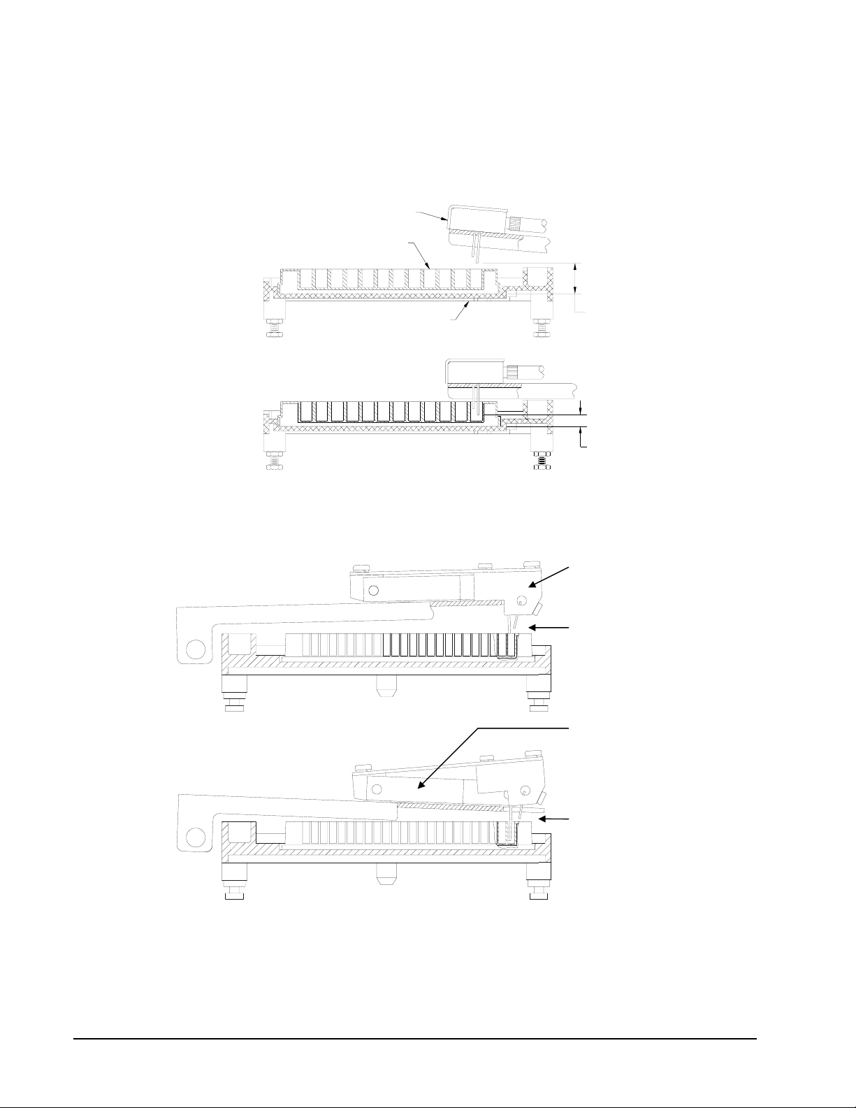
The ELx50/16 models contain the patented dual-manifold design. The 16-channel manifold has 16 sets of
E
dispense and aspirate tubes arranged in a fixed horizontal position relative to each other but located in two
separate manifolds. The two manifolds move independent of each other in the vertical axis. This design
overcomes the problem of fitting both dispense and aspirate tubes into the much smaller 384-well at the same
time, yet it allows for overfill washing of the smaller 384 wells. The dispense tubes are held above the plate
when the dispense manifold reaches a mechanical stop, while the aspirate tubes are able to continue
descending into the wells.
MANIF OLD
MICROPL ATE
CARRIE R
DISPENSE
HEIGHT
ASPIRAT
HEIGHT
Single manifold system of the 8- and 12-channel manifolds.
Dispense manifold
Tubes are
positioned for
overfill washing
Aspirate manifold
Tubes are
positioned for
aspiration
Patented dual-manifold system of the 16-channel manifold.
2-2
Functional Description

The following table shows the washing capabilities of each manifold:
Manifold: Washing Capabilities
8-channel 8-well strips, 96-well plates
8s-channel* 8-well strips, 96-well plates
12-channel 12-well strips, 96-well plates
16-channel 8-well strips, 96-well plates, 384-well plates
* The 8s-channel manifold has shorter dispense tubes for special applications.
The ELx50 washer supports the washing of standard flat, round, and ‘V’ bottom microwells.
Note: The 16-channel manifold uses two aspirating tubes for each well when used with 8-well strips and 96well plates. For these formats, it may be difficult for the tubes to reach the very bottom of round or ‘V’
bottom wells, possibly leading to higher residuals.
An ELx50 washer can be reconfigured to support a different manifold. The level of difficulty for
reconfiguration depends on the current and desired manifolds. Appendix C in the ELx50 Automated Strip
Washer Operator's Manual discusses manifold reconfiguration.
Carrier
There are two possible plate carrier assemblies, p/n 4070526 for the 16-channel washer models and p/n
4070508 for all of the other models.
• 4070508 holds 96-well plates and 1x8 or 1x12 strips, and may be used with
either the 1x8 or 1x12 manifold.
• 4070526 holds 384-well plates, 96-well plates, and 1x8 strips, and may be
used with either a 1x16 or 1x8 manifold.
Strips must be placed in their frames to be held by the carrier. The carrier positions the strips beneath the
manifold where wash solution is aspirated from and dispensed to the test wells. The carrier is removable by
the user and is constructed in a manner which allows for, and with materials that are not damaged by,
chemical decontamination with 0.5% sodium hypochlorite or 70% ethanol. There is a priming/soaking trough
that is the normal home position for the manifold and which is an integral part of the carrier.
Carrier to Manifold Positioning
Carrier movements are controlled by a timing belt and microstepping stepper motor. Positions are configured
for 1x8, 1x12, and 1x16 well columns. Resolution of carrier position is 0.002 inches (minimum). Through
the on-board software, the carrier position can be offset from the factory default settings to optimize washing
performance in a specific plate type or with a specific chemistry.
Manifold Vertical Positioning
The washing manifold moves vertically by a microstepping stepper motor control. It is possible for the user
to offset the vertical position of the aspirating tubes relative to the carrier surface to optimize washing
performance. This offset is in equal increments, no greater than 0.005 inches. The offset range is from 0.100
to 1.0000 inches above the carrier top surface. The manifold vertical positioning design allows for the
manifold to lift as the aspirate tubes touch the well bottom and in that way compensate for vertical
misalignment of the manifold and strips.
Positive Displacement Pump
Wash solution, rinse solution, and disinfecting solutions are delivered to the microwells by a built in positive
displacement pump (syringe pump). The pump draws fluid from the supply bottles and forces it through the
dispense tubes of the manifold. It is possible to dispense at one of nine different flow rates, by running the
Elx50 Strip Washer Service Manual
2-3

pump at different voltages. The flow rate is selectable by the user within the on-board software. The onboard software contains calibration values for each flow rate.
Vacuum Pump
The ELx50 has an internal vacuum pump which is cycled on and off as needed.
Vessels and Connections
There are two 2-liter supply bottles (three if "V" version washer). No self-sealing pressure vessels are
required for fluid supply. Each supply vessel has a hole in its cap that retains a suction tube. A single inlet
supply tube to the strip washer is connected to one or the other of these supply bottles though a pair of
fittings. Typically one bottle will be used for wash buffer solution and the second bottle will be used for
deionized water rinse. The user will disconnect the supply tube from the suction tube of one supply bottle
and connect it to the suction tube of the other supply bottle when switching from one solution to the other.
There is no supply bottle liquid level detection. It is the responsibility of the user to monitor and refill the
supply bottles.
The washer may or may not have the multiple-valves hardware (“V” version washers). Washers equipped
with this hardware prompt the user to enter a supply bottle designation (A, B, or C), at program run-time, and
then use that bottle when running the program.
There is one 2-liter waste vessel. The waste vessel has a sealing closure with one inlet and one outlet. It is
connected to an internal vacuum pump and a vacuum is created in the waste vessel. The vessel is strong
enough to withstand the external atmospheric pressure present under these conditions. The collection vessel
also connects directly to the manifold and solution is aspirated from the test wells by the manifold and pulled
into the collection vessel.
2-4
Functional Description

An optional hydrophobic vacuum filter may be placed in line between the vacuum pump and the collection
vessel. This filter impedes aerosols from entering the vacuum pump and therefore the room, and waste from
being pulled into the vacuum pump in the event of a collection vessel overflow. It is the responsibility of the
user to monitor and periodically empty the waste vessel. There is no waste vessel level detection.
Display and Keypad
The washer is equipped with a 2x24 character LCD display and a 25-key keypad.
Power Supply
The washer is supplied with a 24 volt external power supply and cable.
Decontamination
All exposed surfaces are designed to be chemically disinfected with 0.5% sodium hypochlorite and 70%
ethanol.
Aerosol Cover
The fluid dispensing region is covered with an aerosol cover. The aerosol cover is easily removed to provide
access to the manifold and plate carrier.
Elx50 Strip Washer Service Manual
2-5

Software
The ELx50 washer is operated by on-board software, controllable through the washer’s keypad.
This on-board software, referred to as the “basecode”, has an identifying
Your washer is installed with one of two possible ELx50 basecode part numbers: 4070201 or 4070230. Each
part number in turn has an identifying
version number. If you need to contact Bio-Tek Instruments for
technical assistance, you will be asked for the part number and version
of the basecode currently residing on your washer.
• To locate this information, press these keys from the washer's main menu:
UTIL TESTS CHKSUM
The basecode part number and accompanying version number will appear for
a few seconds, followed by additional configuration information. The display
will automatically return to the main menu.
4070201 basecode supports the following features:
The
• Compatibility with the 8-, 8s-, and 12-channel manifolds.
part number.
• An easy to use, menu-driven interface.
• Ability to create Wash, Prime, Dispense, and Aspirate programs for automated microplate
washing.
• Storage of up to 75 washer programs.
• User-definable washer program names, for rapid recall at program run time.
• Configurable program parameters such as variable soaking, multispeed shaking, bottom
washing, and crosswise aspiration.
• Pre-defined washer programs that can be copied and used as the basis for new programs.
• Pre-defined maintenance programs, including AutoPrime, used to keep the manifold tubes
moist and free from clogging.
• Support for the following languages: English, French, German, Italian, and Spanish.
Note: Contact Bio-Tek for information on changing to a different language.
4070230 basecode supports all of the 4070201 features, plus the following:
The
• Compatibility with the 16-channel manifold, for 384-well plate washing.
• Ability to create Soak and Link programs.
2-6
Functional Description

The basecode is downloaded from a PC to the washer via the serial communication port.
• To prepare the washer for basecode software download, press SHIFT+HIDDEN KEY #1 from the
main menu. Hidden key #1 is between the
CLEAR and ENTER keys.
• To download the software, exit to DOS and type
drive containing the basecode diskette and “
A:\DLOAD 1 and press Enter. “A” represents the
1” represents the com port.
For detailed basecode download instructions, refer to 8291007-AW Field Software Download
Procedure.
Configuration Software
The ELx50 washer requires information downloaded from a configuration software disk, containing
default washer programs, diagnostics programs, and a configuration file (config.50).
It is NOT recommended that you modify the config.50 file. The on-board software provides ample
parameters for adjusting horizontal positions, dispense and aspirate height, etc. Contact Bio-Tek engineering
with any specific questions or suggestions.
The configuration software is downloaded from a PC to the washer via the serial communication port,
using Bio-Tek's Download Utility.
• To prepare the washer for configuration software download, press SHIFT+HIDDEN KEY #2 from the
main menu. Hidden key #2 is between the
• For configuration download instructions, refer to 8291007-AW Field Software Download Procedure.
Main Menu and Previous Screen keys.
Elx50 Strip Washer Service Manual
2-7

2-8
Functional Description

Section 3
Error Codes
Homing an Axis
When any motor axis is moved to sensor home, its position is set to 0. Sensor home and the home position are not
necessarily the same. The following is a description of how each axis is moved to sensor home. For the Carrier and Syringe
axis there are two ways the motor can move to sensor home:
1. If the carrier or syringe is on the sensor(typically at home) then the axis is moved off the sensor plus 3 full
steps. The axis is then moved toward the sensor until the sensor is marked.
2. Otherwise the carrier or syringe axis is off the sensor and the axis is moved toward the sensor until the sensor is
marked.
For the manifold, the process is similar:
1. If the sensor is open (typically at home), then the axis is moved away from the sensor until the sensor is
marked, plus 3 full steps. The manifold is then moved toward the sensor until the sensor is open.
2. Otherwise the manifold axis is moved toward the sensor until the sensor is open.
Carrier Axis Home Position
The carrier home position is defined to be sensor home plus an offset. This offset, Carrier Home Offset, is presently
defined in System Configuration The only time that sensor home and the home position are the same is if this value
is set to zero.
Manifold Axis Home Position
The manifold home position is defined to be sensor home.
Syringe Axis Home Position
The syringe home position is defined to be sensor home plus an offset. This offset, Syringe Home Offset, is
presently defined in System Configuration The only time that sensor home and the home position are the same is if
this value is set to zero.
Verifying an Axis
Manifold
When the verification is performed on this axis, the software compares the number of steps observed at its present position to
the actual number of steps required to move the axis back to the sensor home position. At the completion of any program,
the manifold position is verified. There are two scenarios:
1. If the manifold is on the sensor or the observed motor position is less than 3 full steps from the sensor, then the manifold
is moved away from the sensor 6 full steps. The manifold is then moved toward the sensor until the sensor is marked. If
the observed motor position is outside the range of -3 full steps to plus 3 full steps inclusive, then an error is generated.
2. Otherwise the manifold is moved toward the sensor until the sensor is marked. If the observed motor position is outside
the range of -3 full steps to plus 3 full steps inclusive, then an error is generated.
Syringe
There are five distinct actions that are being tested to insure the syringe is functioning correctly.
1. At the beginning of each syringe intake stroke, the software checks to insure that the optical sensor is marked.
If the sensor is not marked, an error is generated.
2. During the syringe intake stroke, the software detects how many steps the syringe travels before the sensor
changes from marked to open. If this number of steps falls outside the specified range (syringe sensor clear +/Syringe FMEA Range) then an error is generated.
3. At the beginning of each syringe dispense stroke, the software checks to insure that the optical sensor is open.
If the sensor is not open then an error is generated.
4. After completion of a Dispense, Prime or Wash Program, the software checks to insure that the optical sensor is
marked. If the sensor is not marked and error is generated.
Elx50 Strip Washer Service Manual
3-1

5. When power-up or self test is performed, the number of steps from syringe home position to clear the sensor is
determined (syringe sensor clear). If this value is greater than the value specified, Syringe_FMEA_Offset, then
an error is generated. This determined value is then used during step 2 along with Syringe FMEA Range to
determine a failure.
Carrier
When the verification is performed on this axis, the software compares the number of steps observed at its present position to
the actual number of steps required to move the axis back to the sensor home position. At the completion of a dispense,
aspirate or wash program, the carrier position is verified. There are two scenarios:
1. If the carrier is on the sensor or the observed motor position is less than 3 full steps from the sensor, then the
carrier is moved away from the sensor 6 full steps. The carrier is then moved toward the sensor until the sensor
is marked. If the observed motor position is outside the range of -3 full steps to plus 3 full steps inclusive, then
an error is generated.
2. Otherwise the carrier is moved toward the sensor until the sensor is marked. If the observed motor position is
outside the range of -3 full steps to plus 3 full steps inclusive, then an error is generated.
Error Codes
Non-fatal errors :
Error Error Code Brief Description
ABORT_ERR 0x0100 wash function aborted
NO_SENSOR_ERR 0x0200 (*motor) couldn't find optical-sensor
AUTOCAL_JIG_ERR 0x0300 (*motor) couldn't find edge of hole in jig
MOTOR_VERIFY_ERR 0x0400 (*motor) failed positional verify
UNDEF_PROG_TYPE_ERR 0x0500 undefined program type specified
PROGRAM_NUM_ERR 0x0600 invalid (assay number)
PROGRAM_SET_ERR 0x0700 invalid write attempt
PROGRAM_DEL_ERR 0x0800 invalid delete attempt
SYR_VOLUME_TO_LARGE 0x0900 syringe volume to large
PROGRAM_CHECKSUM_ERR 0x0A00 checksum failure (assay number)
MANIFOLD_AUTOCAL_ERR 0x0B00 invalid manifold for calibration
INVALID_BUFFER_ERR 0x0C00 invalid buffer selected
CAL_CHECKSUM_ERR 0x0D00 failed calibration checksum test
DISPENSE_RATE_ERR 0x0E00 dispense rate is invalid for manifold type
DISPENSE_VOLUME_ERR 0x0F00 dispense volume invalid for manifold type
CNFG_DATA_ERR 0x1000 necessary configuration data missing
CNFG_CHECKSUM_ERR 0x1100 failed configuration checksum test
CAL_DATA_ERR 0x1200 necessary calibration data missing
MOTOR_NOT_HOMED_ERR 0x1300 (*motor) not homed successfully
AUTOCAL_ABORT_ERR 0x1400 autocal of washer was aborted
MALLOC_ERR 0x1900 memory allocation failure
ASPIRATE_POS_ERR 0x1A00 Carrier offset position is out of range for present manifold
DISPENSE_POS_ERR 0x1B00 Carrier offset position is out of range for present manifold
SYRINGE_FMEA_ERR 0x1C00 1=sensor not found at start of syringe aspirate stroke.
2=sensor not open at start of dispense stroke.
3=syringe aspirate stroke failure
4=sensor verify after last syringe stroke in program failed
5= sensor clear from home position too many steps
MANIFOLD_POS_ERR 0x1D00 could not calculate manifold position for offset provided
AUTOCAL_CHECKSUM_ERR 0x1E00 autocal checksum error
3-2
Error Codes
*Motor Identification
Motor Axis Axis Number
Manifold 0
Carrier 1
Syringe 2
Fatal errors:
Error Error Code Brief Description
TCB_NOT_AVAIL_ERR 0xA100 task control block not available
READ_NOT_AVAIL_ERR 0xA200 reader function already in use
NOT_AVAIL_ERR 0xA300 (device) not available
CHECKSUM_ERR 0xA400 failed code checksum test on power up
POWER_ERR 0xA500 power dropped below safe level
QFLASH_TIMEOUT_ERR 0xA600 quick flash configuration timed out
QFLASH_ERR 0xA700 quick flash read didn't match write
All of these items are system configuration values which can be changed and loaded via extensions without a rebuild of the
software:
System Configuration
Parameter Default Range Units
Vacuum Pump Startup Delay 0 0-10 seconds
Vacuum Pump Dissipation Delay 10 0-10 seconds
Trough Dispense Height 96 12-180
Trough Aspirate Height 30 12-180
Trough Clearance Height 146 12-180
Prime Aspirate Delay 3000 0-5000 milliseconds
Crosswise Clearance Height 64 12-180
Extended Soak Delay 30 15-600 seconds
Extended Soak Vacuum Delay 30 15-600 seconds
Syringe Backlash 7 0-100 full steps
Volume per Step (syringe) 12.32 0-1000 ul/step
Maximum Stroke (syringe) 9000 0-65000 ul
Carrier Overshoot 2 0-10 full steps
Carrier Home Offset 20 0-50 full steps
Plate Clearance 146 12-180
Valve Open Delay 0 0-65000 milliseconds
Valve Close Delay 0 0-65000 milliseconds
Syringe Home Offset -160 -1600 to +1600 16th steps, full step resolution
Syringe FMEA Offset 560 0-16000 16th steps, full step resolution
Syringe FMEA Range 160 0-16000 16th steps, full step resolution
See the Operation section of the operator’s manual for current information.
Elx50 Strip Washer Service Manual
3-3

3-4
Error Codes
 Loading...