

Page 1
Operator’s Manual
BioStack
™
Microplate Stacker
Page 2

Page 3

BioStack™ Microplate Stacker
Operator's Manual
© 2018
BioTek Instruments, Inc.
PN 7311000 Rev AH
Page 4

ii | BioStack Operator's Manual
Notices
BioTek® Instruments, Inc.
Highland Park, PO Box 998
Winooski, VT USA 05404-0998
© 2018, BioTek Instruments, Incorporated. No part of this publication may be
reproduced, transcribed, or transmitted in any form or by any means electronic or
mechanical, including photocopying and recording, for any purpose other than the
purchaser's use without the written permission of BioTek Instruments, Inc.
Trademarks
BioTek® is a registered trademark, and BioStack™, 405™ Microplate Washer,
EL406™, ELx405™, Eon™, Epoch™, Gen5™, Liquid Handling Control™,
MicroFill™, MultiFlo™, MultiFlo™ FX, PowerWave™, Precision™, Precision
Power™, Cytation™ and Synergy™ are trademarks of BioTek Instruments, Inc.
Microsoft® and Windows® are registered trademarks of Microsoft Corporation in
the United States and/or other countries.
All other trademarks are the property of their respective holders.
Restrictions and Liabilities
Information in this document is subject to change and does not represent a
commitment by BioTek Instruments, Inc. Changes made to the information in this
document will be incorporated in new editions of the publication. No
responsibility is assumed by BioTek for the use or reliability of software or
equipment that is not supplied by BioTek or its affiliated dealers.
BioStack™ Microplate Stacker
Page 5

Notices| iii
Contents
Notices ii
Contact Information vi
Global Service and Support vi
Customer Service and Sales vi
Service/Technical Assistance Center (TAC) vi
European Coordination Center/Authorized European Representative vi
Revision History vii
Document Conventions xi
Intended Use Statement xi
Quality Control xii
Warranty and Product Registration xii
Warnings xii
Hazards xiii
Precautions xiv
CE Mark xvi
Directive 2014/30/EU: Electromagnetic Compatibility xvi
Directive 2014/35/EU Low Voltage (Safety) xvi
Directive 2012/19/EU: Waste Electrical and Electronic Equipment xvii
Directive 98/79/EC: In Vitro Diagnostics (if labeled for this use) xvii
Electromagnetic Interference and Susceptibility xvii
USA FCC CLASS A xvii
Canadian Department of Communications Class A xvii
User Safety xviii
Safety Symbols xix
BioStack 3 and BioStack 4: Secure Gripper Before Moving xx
Introduction 1
Introducing the BioStack 2
Product Description 3
BioStack 4: Notes about Handling Lidded Plates 4
Package Contents 6
Optional Accessories 6
Specifications 9
Stay-On Lid Mode (BioStack 4 Only) 10
Installation 13
Upgrade Scenarios 14
Unpack and Inspect the Instrument 15
Setting Up the BioStack 17
Remove the Shipping Hardware—BIOSTACK2WR 18
Remove the Shipping Hardware—BioStack 3 20
Remove the Shipping Hardware—BioStack 4 23
Wrist Angle Setting Requirements 26
0 Degree Orientation for Liquid Handlers 27
Dip Switch Settings 28
Change Setting for Wrist Angle 29
Change Setting for 50-Plate Stacks 30
BioTek Instruments, Inc.
Page 6

iv | BioStack Operator's Manual
Test Plates for Compatibility—BioStack 4 Only 30
Connect to Power 31
Connect to Computer 32
Connect to Liquid Handler 33
Where to Go Next 35
Repacking the BioStack 36
Install the Shipping Hardware—BioStack2WR 37
Install the Shipping Hardware—BioStack 3 37
Install the Shipping Hardware—BioStack 4 38
Repacking—Install Shipping Panel 39
Operation 41
Before You Start 42
Load Plates into Input Stack 43
Load Plates Using the Pedestal 44
Supported Microplate Types and Dimensions 45
Processing Microplates 46
Controlling the BioStack: 46
Stopping Plate Processing 47
Restack the Plates 49
Processing Plates with Lids 49
Plate De-Lidding: How It Works 50
Prevent Condensation on Plate Lids 51
Plate Lid Definition Files 52
Microplate and Lid Dimensions 53
Plate Lid Advanced Dimensions 54
Start Up the BioStack 57
Maintenance 59
Overview 60
Recommended Maintenance Schedule 60
Warnings and Precautions 61
Required Materials 61
Routine Cleaning Procedure 63
Decontamination 64
Tools and Supplies 65
Decontaminate the BioStack 65
Cleaning and Lubricating the Linear Ways 66
Qualification 69
Overview 70
Recommended Qualification Schedule 70
Installation Qualification 72
Operational Qualification Procedure 72
Troubleshooting & Error Codes 73
Troubleshooting 74
Communication Error Codes 74
BioStack Instrument Errors 76
Plate Lid Definition Errors 82
BioStack™ Microplate Stacker
Page 7

Notices| v
Washer or Dispenser Communication Error Codes 85
BioStack Sensor Numbers 86
BioStack Motor Numbers 87
Interfacing Instrument Numbers 87
Plate Stacked Height 88
Change Setting for Low-Profile Plates 89
Loosen Plate Carrier Set Screws - BioStack 4 Only 90
Adjust the Stack Dogs 91
Install the Barcode Scanner 93
Barcode Scanner Overview 94
Install the Barcode Scanner 94
Change Dip Switch Setting for Barcode Scanner 97
Install the Scanner Cable Duct 97
Preparing and Attaching Barcode Labels 99
Scanner Test with Readers 101
To Report Barcodes with Reader Results 101
Scanner Test with Precision/XS 103
To Report Scanned Codes with Precision/XS 104
BioTek Instruments, Inc.
Page 8

vi | BioStack Operator's Manual
Contact Information
BioTek Instruments, Inc.
Highland Park, P.O. Box 998
Winooski, Vermont 05404-0998 USA
Global Service and Support
BioTek instrument service and repair is available worldwide at several of BioTek’s
International Service Centers and in the field at your location. To arrange for service
or repair, contact the office nearest you; visit www.biotek.com for up-to-date
contact information. For customer service, sales, and technical assistance, refer to
the information below.
Customer Service and Sales
Internet: www.biotek.com
Phone:
802-655-4740(outsidetheUS)
Fax: 802-655-7941
Email: customercare@biotek.com
888-451-5171 (toll-free in the US)
Service/Technical Assistance Center (TAC)
Phone:
802-655-4740(outsidetheUS)
Fax: 802-654-0638
Email: tac@biotek.com
800-242-4685 (toll-free in the US)
European Coordination Center/Authorized European Representative
BioTek Instruments GmbH
Kocherwaldstrasse 34
D-74177 Bad Friedrichshall
Germany
Internet: www.biotek.de
BioStack™ Microplate Stacker
Page 9

Revision History| vii
Phone:
Fax: +49(0)7136968111
Email: info@biotek.de
+49 (0) 7136 9680
Revision History
Rev Date Changes
A 11/2002 First issue.
B 5/2003 Throughout: Clarified the compatibility of the ELx405 with the BioStack by
specifying the Washer’s Auto Plate and Select models only. Updated
contact information, Safety Symbols, and Warranty.
C 10/2003 Preface: Updated the Intended Use statement to distinguish between the
European Union and all other jurisdictions.
D 06/2004 Throughout: Reformatted manual for cosmetic effect. Added references
about compatibility of the BioStack with the ELx405 HT and ELx405 Select
CW Microplate Washers. Added new sections about compatibility,
installation, operation, alignment, etc., of the Precision and Precision XS.
Revised the Technical Support section and added new sections on Depot
Service Contracts and Applications Support. Enhanced Introduction,
Installation, Operation, and Maintenance chapters.
E 06/2005 Throughout: Added information on the new barcode scanner and USB port.
Changed ELx405 “Auto” model to “ELx405.”
Moved instructions from former Appendix B, Serial Cable Connections and
Appendix C, Mounting the Aligning Plates and Posts into Chapter 3,
Installation.
Chapter 5: Simplified/clarified IQ and OQ sections. Chapter 7: Added KC4
error codes for BioStack operation with readers, and BioStack barcode
scanner error codes.
F 05/2006 Added instructions for using Gen5 software. Preface: Updated safety
information and removed Warranty, Registration Card, and Registration
Online sections in Preface. Added laser beam warning. Appendix B: Added
laser beam warning.
G 07/2006 Added instructions for installing/operating the BioStack with the Synergy 2.
H 12/2006 Added instructions for installing and operating the BioStack with the
NanoQuot. In Chapter 5 and Appendix B: Added the Barcode Scanner Test
as an optional IQ and OQ test.
BioTek Instruments, Inc.
Page 10

viii | BioStack Operator's Manual
Rev Date Changes
I 06/2007 Added instructions for installing and operating the BioStack with the
Synergy 4. Updated error code information. Incorporated manual update
revision H1 as Appendix C, Reconfiguration of the BioStack. Added
Appendix D, Required Software Versions.
J 08/2007 Added references to the Liquid Handling Control (LHC) Software throughout
the manual, and instructions for installation/operation of the software for
PC control of the BioStack and ELx405.
K 10/2007 Added instructions for installing and operating the BioStack with the
MicroFlo Select.
L 03/2008 Added instructions for installing and operating the BioStack with the
PowerWave XS2. Changed “μFill” to “MicroFill.”
M 06/2008 Changed “Bio-Stack” to “BioStack.” Added references to the fixed wrist
model (PN BIOSTACK2) and rotational wrist model (PN BIOSTACK2WR).
Added instructions for installation/operation of the new models with
interfacing instruments.
N 10/2008 Added instructions for installing and operating the BioStack with the EL406.
Changed “Alignment Kit” to “Integration Kit” throughout. Added more
information about installation of two BioStacks with two interfacing
instruments (ELx405, MicroFlo Select, EL406).
O 12/2008 Added instructions for installing and operating the BioStack with the
Synergy Mx. Removed references to obsolete BioStack PN BIOSTACK.
P 04/2009 Added information regarding instrument control of the EL406 and
installation/operation instructions for controlling the BioStack and EL406
via the keypad. Added more information about how the BioStack barcode
scanner works in Appendix B. Added instructions or notes throughout the
manual instructing the user to turn the BioStack on before the interfacing
instrument, and to manually raise the BioStack’s claw/gripper above the
interfacing instrument’s plate carrier or supply station (Precision) before
turning the BioStack on.
Q 01/2010 Added instructions for installing and operating the BioStack with the
Synergy H4 reader.
R 09/2010 Overall: Streamlined and rearchitected content to enhance usability and
support maintenance and reuse. Moved installation and operation
instructions, software version compatibility tables, software data sheets,
and information on obtaining software version information out of the main
Operator’s Manual and into individual, instrument-specific PDF files on the
BioStack Operator’s Manual CD. Added support for the MultiFlo Dispenser.
Preface: Updated Intended Use Statement; Warnings, Hazards, and
BioStack™ Microplate Stacker
Page 11

Revision History| ix
Rev Date Changes
Precautions; Directives; and Safety Symbols.
Chapter 1 Introduction: Updated Package Contents and Optional
Accessories lists. Chapter 2 Installation: Added “Configure for 50-Plate
Stacks.” Chapter 5 Instrument Qualification: Removed IQ Checklists.
Moved the Software Data Sheets to the individual instrument-specific PDF
files. Chapter 6 Error Codes: Removed error code tables for MicroFlo and
EL406 Interface Software, and Gen5/KC4 Function Call Errors.
S 11/2010 Added instructions for installing and operating the BioStack with the
Synergy H1 reader. Emphasized the importance of orienting microplates in
the input stack to match the expected placement of well A1 on the
interfacing instrument’s plate carrier.
T 8/2011 Added instructions for installing/operating the BioStack with the Eon,
Epoch.
U 3/2012 Added instructions for installing and operating the BioStack with the 405
TS. Added references to the 10-plate stacks.
V 6/2012 Added support for BIOSTACK3WR (for liquid handlers). Removed
references to BioStack2. Added ‘Service’ and ‘Accessories’ hazard
warnings. Added ‘Spare Parts’ precaution. Changed all references from
claw/gripper to gripper. Added Wrist Angle Setting Requirement and Dip
switch Settings content. Revised descriptions of the microplate
requirements. Replaced former Appendix B, Microplate Stack
Adjustment/Configuration for Half-Height Plates with section in
Troubleshooting chapter: Adjust Stack Dogs. Updated error codes and
added Troubleshooting guidelines to the same chapter. Omitted former
Appendix C, Information for External Developers, as it was obsolete.
Updated format and text styles, replaced some drawings with photos.
Revised the liquid handler instrument-specific sections; conversely, the
reader instrument-specific PDFs are unchanged since the last revision. The
Nanoquot instrument-specific section has been omitted.
W 7/2012 Added support for BioStack3 for readers and for controlling both BioStack
models using Gen5 alone (i.e. BioStack PC Control Software is no longer
needed for the readers). Consolidated the Integration Kits when applicable,
i.e. universal aligning base plates support both BioStack models. Removed
references to obsolete aligning base plate in instrument-specific
instructions. Added units to the barcode label graphic.
X 4/2013 Added instructions for installing and operating the BioStack with the
Cytation 3. Corrected or improved content based on suggestions from field
staff, including deleting the statement that barcode labels can be purchased
from BioTek. Added references to the rubber band that secures the
BioStack3's wrist during shipping. Recommended using rubber bands to
BioTek Instruments, Inc.
Page 12

x | BioStack Operator's Manual
Rev Date Changes
secure gripper before moving the BioStack 3.
Y 11/2013 Added instructions for installing and operating the BioStack with the
MultiFlo FX. Added Precision Universal models (PRC384U) to the list of
instruments that are not BioStack-compatible. Restored references to, and
added a diagram for 0° integration for liquid handlers and the
BIOSTACK2WR. Added "Space Requirement Dimensions" for most
interfacing instruments.
Z 12/2013 Introduced BioStack 4 and its support of plate lids during processing. Added
hazard label and description: cutting fingers/hand. Added "Plate
Compatibility Test" for BioStack4 only. Added support for the Synergy Neo
- BioStack4 integration.
AA 6/2014 Added support for new instruments: Epoch2 and Synergy HTX. Added a
warning that the PowerWave HT is not compatible with the BioStack 4 and a
"strong recommendation" to measure the plate and lid type before use to
verify they meet the minimum requirements for de-lidding operations with
the BioStack 4.
AB 9/2014 Updated specifications to include certain low-density plates with lids that
are supported in "stay-on lid" mode. Added references to stay-on lid mode
where applicable. Corrected the space requirement for liquid handlers:
increased the depth required by six inches to account for wrist movement.
AC 12/2014 Added support for Cytation 5. Updated the "Stay-on Lid" mode description
to describe the newly relabeled stacks required to support this feature, i.e.,
Tall Lidded Plate Stacks. Updated notice of compliance with EU Directives.
AD 2/2015 Updated Synergy Neo integration instructions to match new and improved
alignment hardware. Added new 28 volt power supply to parts list.
AE 3/2015 Reverted contents to match revision AC.
AF 7/2015 Added support for Synergy Neo2, updated Contact Information, changed
RMA to Service Call Notice (SCN) number, updated Synergy Neo and
Synergy Neo2 integration kit to PN 7310055
AG 2017 Updated PN for replacement shipping materials 7313002 to 1163003;
removed reference to the ANSI standard in the microplate specification section; add note to “Install and Run BioStack with the Synergy H1” to point
out position of bracket on alignment plate, which varies depending on
which BioStack is used; added Cytation 1 support; resolved EPR 24692 by
adding error code 2002 to the list; modified instructions for installing software and testing communication in the Install and Operate the BioStack
with Precision document; added USB and serial cable part numbers to the
fluid interfacing instrument documents.
BioStack™ Microplate Stacker
Page 13
Document Conventions| xi
Rev Date Changes
AH 12/2018 Updated Epoch 2 information to correspond with the updated Epoch 2 instru-
ment; corrected alignment plate PN for Synergy H1; updated the drawing
of the Cytation showing the space needed for an instrument with a Cooling
Accessory installed; updated PN for BioStack2 shipping container to PN
7310014; updated BioStack leg PN for use with Epoch 2 to 7310570;
updated the PN for the baseplate for the Microflo FX to 7312138; added
error code 020D.
Document Conventions
This manual uses the following typographic conventions:
n This note format calls attention to important information.
Warnings are presented in this style to call attention to potential hazards and
other safety concerns.
This icon calls attention to important safety information.
Tips and suggestions for improving performance are formatted this way.
Intended Use Statement
The BioStack Microplate Stacker is an automated microplate stacking system that is
designed to systematically transfer a stack of microplates to and from compatible
BioTek laboratory instruments wherever washing, dispensing, pipetting, or reading
of multiple microplates is performed.
If the instrument has an “IVD” label it may be used for clinical and non-clinical
purposes, including research & development. If there is no such label the
instrument may only be used for research & development or other non-clinical
purposes.
BioTek Instruments, Inc.
Page 14
xii | BioStack Operator's Manual
Quality Control
It is considered good laboratory practice to run laboratory samples according to
instructions and specific recommendations included in the assay package insert for
the test to be conducted. Failure to conduct Quality Control checks could result in
erroneous test data.
Warranty and Product Registration
Please take a moment to review the Warranty information that shipped with your
product. Please also register your product with BioTek to ensure that you receive
important information and updates about the product(s) you have purchased.
You can register online through BioTek’s Customer Resource Center (CRC) at
www.biotek.com or by calling 888/451-5171 or 802/655-4740.
Warnings
Operate the instrument on a level, stable surface away from excessive
humidity.
When operated in a safe environment, according to the instructions in this
manual, there are no known hazards associated with the BioStack. However,
the operator should be aware of certain situations that could result in serious
injury: see Hazards and Precautions.
BioStack™ Microplate Stacker
Page 15
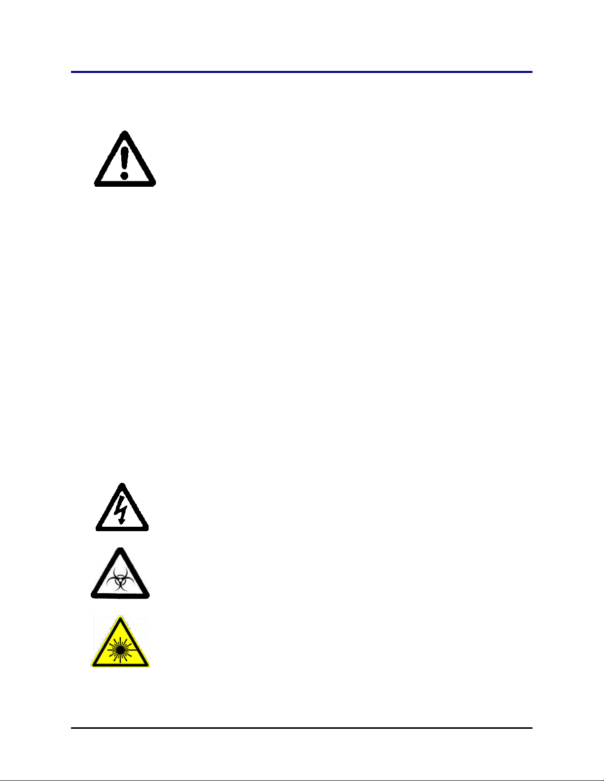
Hazards
The following hazard warnings are provided to help avoid injury:
Warning! Power Rating. The instrument’s power supply or power cord must
be connected to a power receptacle that provides voltage and current within the
specified rating for the system. Use of an incompatible power receptacle may
produce electrical shock and fire hazards.
Hazards| xiii
Warning! Electrical Grounding. Never use a plug adapter to connect primary
power to the external power supply. Use of an adapter disconnects the utility
ground, creating a severe shock hazard. Always connect the power cord directly to
an appropriate receptacle with a functional ground.
Warning! Service. Only qualified technical personnel should perform service
procedures on internal components.
Warning! Accessories. Only accessories which meet the manufacturer’s
specifications shall be used with the instrument.
Warning! Liquids. Avoid spilling liquids on the instrument; fluid seepage into
internal components creates a potential for shock hazard or instrument damage. If a
spill occurs while a program is running, abort the program and turn the instrument
off. Wipe up all spills immediately. Do not operate the instrument if internal
components have been exposed to fluid.
Warning! Unspecified Use. Failure to operate this equipment according to the
guidelines and safeguards specified in this manual could result in a hazardous
condition.
Warning! Software Quality Control. The operator must follow the
manufacturer’s assay package insert when modifying software parameters and
establishing reading, washing, or dispensing methods. Failure to conduct quality
control checks could result in erroneous test data.
Warning! Internal Voltage. Always turn off the power switch and unplug the
power supply before cleaning the outer surface of the instrument.
Warning! Potential Biohazards. Some assays or specimens may pose a
biohazard. Adequate safety precautions should be taken as outlined in the assay’s
package insert. This hazard is noted by the symbol shown here. Always wear safety
glasses and appropriate protective equipment, such as chemically resistant rubber
gloves and apron.
Warning! Laser Beam. Serious eye injury may occur if you stare directly into
the laser beam of the barcode scanner during operation of the scanner. This hazard
is noted by the symbol shown here. Do not look directly into the laser beam during
operation of the scanner.
BioTek Instruments, Inc.
Page 16
xiv | BioStack Operator's Manual
Warning! Pinch Hazard. Some areas of the instrument or its components can
present pinch hazards when the instrument is operating. These areas are marked
with the symbol shown here. Keep hands/fingers clear of these areas when the
instrument is operating.
Warning! Cutting of Fingers or Hand Hazard. The metal plate gripper
presents a cutting hazard to fingers/hands when the instrument is operating. The
gripper is marked with the symbol shown here. Keep fingers/hands away from the
gripper when the instrument is operating.
Precautions
The following precautions are provided to help avoid damage to the instrument(s):
Caution: Service. The instrument should be serviced by BioTek-authorized
service personnel. Only qualified technical personnel should perform troubleshooting
and service procedures on internal components.
Caution: Spare Parts. Only approved spare parts should be used for
maintenance. The use of unapproved spare parts and accessories may result in a
loss of warranty and potentially impair instrument performance or cause damage to
the instrument.
Caution: Environmental Conditions. Do not expose the instrument to
temperature extremes. For proper operation, temperaturess near the instrument
should remain within the range listed in the Specifications section. Performance
may be adversely affected if temperatures fluctuate above or below this range.
Caution: Sodium Hypochlorite. Do not expose any part of the instrument to
the recommended diluted sodium hypochlorite solution (bleach) for more than 20
minutes. Prolonged contact may damage the instrument surfaces. Be certain to
rinse and thoroughly wipe all surfaces.
Caution: Power Supply. Only use the power supply shipped with the
instrument. Operate this power supply within the range of line voltages listed on it.
Caution: Disposal. Dispose of the instrument according to Directive
2002/96/EC, “on waste electrical and electronic equipment (WEEE),” or local
ordinances.
Caution: Warranty. Failure to follow preventive maintenance protocols may
void the warranty.
Caution: Shipping Hardware. All shipping hardware (e.g., shipping panel,
shipping block, carrier shipping screws, etc.) must be removed before operating the
instrument and reinstalled before repackaging the instrument for shipment.
Caution: Waste Sensor Port (for customers who have purchased the
BioStack for use with the ELx405, 405 TS/LS, or EL406). The waste sensor port on
the back of the washer/dispenser is the same type as the 24-VDC power connector
on the back of the BioStack. Do not plug the BioStack’s external power supply into
BioStack™ Microplate Stacker
Page 17

Precautions| xv
the washer’s/dispenser’s port; it will permanently damage internal components.
Caution: Aligning Posts. When installing the BioStack’s four aligning posts,
use caution not to cross thread these parts. Finger-tighten only!
Caution: BioStack Barcode Scanner Mirror. Do not scratch or damage
the mirror when unpacking or installing the barcode scanner.
Caution: Electromagnetic Environment. Per IEC 61326-2-6 it is the user’s
responsibility to ensure that a compatible electromagnetic environment for this
instrument is provided and maintained in order that the device will perform as
intended.
Caution: Electromagnetic Compatibility. Do not use this device in close
proximity to sources of strong electromagnetic radiation (e.g., unshielded
intentional RF sources), because these may interfere with the proper operation.
BioTek Instruments, Inc.
Page 18

xvi | BioStack Operator's Manual
CE Mark
Based on the testing described below and information contained
herein, this instrument bears the CE mark.
n Note: Refer to the Declaration of Conformity for specific details.
Directive 2014/30/EU: Electromagnetic Compatibility
Emissions—Class A
The system has been type-tested by an independent, accredited testing
laboratory and found to meet the requirements of EN 61326-1: Class A for
Radiated Emissions and Line Conducted Emissions.
Verification of compliance was conducted to the limits and methods of EN 55011
(CISPR 11) Class A. In a domestic environment it may cause radio interference,
in which case, you may need to take measures to mitigate the interference.
Immunity
The system has been type-tested by an independent, accredited testing
laboratory and found to meet the requirements of EN 61326-1 and EN 61326-2-6
for Immunity. Verification of compliance was conducted to the limits and
methods of the following:
EN 61000-4-2, Electrostatic Discharge
EN 61000-4-3, Radiated EM Fields
EN 61000-4-4, Electrical Fast Transient/Burst
EN 61000-4-5, Surge Immunity
EN 61000-4-6, Conducted Disturbances from RFI
EN 61000-4-11, Voltage Dips, Short Interruptions and Variations
Directive 2014/35/EU Low Voltage (Safety)
The system has been type-tested by an independent testing laboratory and was
found to meet the requirements of this Directive. Verification of compliance was
conducted to the limits and methods of the following:
EN 61010-1, “Safety requirement for electrical equipment for measurement,
control and laboratory use. Part 1, General requirements.”
EN 61010-2-081, “Particular requirements for automatic and semi-automatic
laboratory equipment for analysis and other purposes.”
BioStack™ Microplate Stacker
Page 19

Electromagnetic Interference and Susceptibility| xvii
Directive 2012/19/EU: Waste Electrical and Electronic Equipment
Disposal Notice: Dispose of the instrument according to Directive 2012/19/EU,
“on waste electrical and electronic equipment (WEEE)” or local ordinances.
Directive 98/79/EC: In Vitro Diagnostics (if labeled for this use)
n Product registration with competent authorities
n Traceability to the U.S. National Institute of Standards and Technology (NIST).
EN 61010-2-101 Particular requirements for in vitro diagnostic (IVD) medical
equipment.
Electromagnetic Interference and Susceptibility
USA FCC CLASS A
RADIO AND TELEVISION INTERFERENCE
NOTE: This equipment has been tested and found to comply with the limits
for a Class A digital device, pursuant to Part 15 of the FCC Rules. These limits
are designed to provide reasonable protection against harmful interference
when the equipment is operated in a commercial environment. This equipment
generates, uses, and can radiate radio frequency energy and, if not installed
and used in accordance with the instruction manual, may cause harmful
interference to radio communications. Operation of this equipment in a
residential area is likely to cause harmful interference, in which case the user
will be required to correct the interference at their own expense.
In order to maintain compliance with FCC regulations shielded cables must be
used with this equipment. Operation with non-approved equipment or
unshielded cables is likely to result in interference to radio and television
reception.
Canadian Department of Communications Class A
This digital apparatus does not exceed Class A limits for radio emissions from
digital apparatus set out in the Radio Interference Regulations of the Canadian
Department of Communications.
Le present appareil numerique n'émet pas de bruits radioelectriques depassant
les limites applicables aux appareils numerique de la Class A prescrites dans
le Reglement sur le brouillage radioelectrique edicte par le ministere des
Communications du Canada.
BioTek Instruments, Inc.
Page 20

xviii | BioStack Operator's Manual
User Safety
This device has been type-tested by an independent laboratory and found to meet
the requirements of the following:
l Underwriters Laboratories UL 61010-1 “Safety requirements for electrical
equipment for measurement, control and laboratory use; Part 1: general
requirements.”
l Canadian Standards Association CAN/CSA C22.2 No. 61010-1 “Safety
requirements for electrical equipment for measurement, control and
laboratory use; Part 1: general requirements.”
l EN 61010 Standards. See CE Mark on page xvi.
BioStack™ Microplate Stacker
Page 21
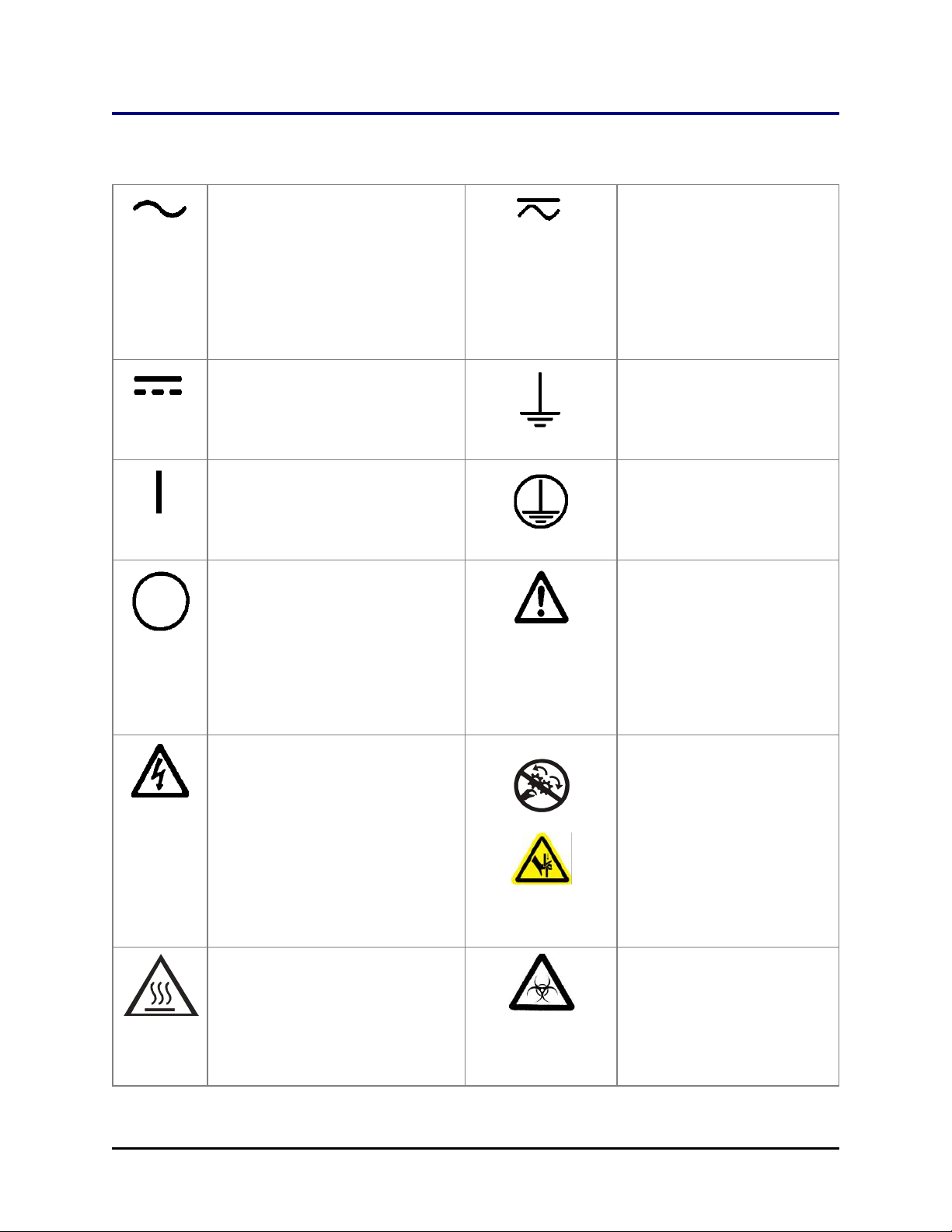
Safety Symbols
Some of these symbols appear on the instrument or accessories:
Alternating current
Courant alternatif
Wechselstrom
Corrientealterna
Correntealternata
Safety Symbols| xix
Both direct and alternating
current
Courant continu et courant
alternatif
Gleich - und Wechselstrom
Corriente continua y
corrientealterna
Corrente continua e
correntealternata
Direct current
Courant continu
Gleichstrom
Corriente continua
Corrente continua
On (Supply)
Marche (alimentation)
Ein (VerbindungmitdemNetz)
Conectado
Chiuso
Off (Supply)
Arrêt (alimentation)
Aus (TrennungvomNetz)
Desconectado
Aperto
(sconnessionedallaretedialimentazi
one)
Warning, risk of electric shock
Attention, risque de choc électrique
Gefährlicheelektrischeschlag
Precaución, riesgo de
sacudidaeléctrica
Attenzione, rischiodiscossaelettrica
Earth ground terminal
Borne de terre
Erde (Betriebserde)
Borne de tierra
Terra (difunzionamento)
Protective conductor terminal
Borne de terre de protection
Schutzleiteranschluss
Borne de tierra de protección
Terra diprotezione
Caution (refer to
accompanying documents)
Attention (voir documents
d’accompanement)
AchtungsieheBegleitpapiere
Atención (vease los
documentosincluidos)
Attenzione, consultare la doc
annessa
Warning, risk of crushing or
pinching
Attention, risqued’écrasement
et pincement
Warnen, Gefahr des
Zerquetschens und Klemmen
Precaución, riesgo del
machacamiento y sejeción
Attenzione,
rischiodischiacciareedintrappol
arsi
Warning, hot surface
Attention, surface chaude
Warnen, heißeOberfläche
Precaución, superficiecaliente
Attenzione, superficiecalda
Warning, potential biohazards
Attention,
risquesbiologiquespotentiels
Warnung!
MoeglichebiologischeGiftstoffe
Atención, riesgosbiológicos
Attenzione, rischiobiologico
BioTek Instruments, Inc.
Page 22
xx | BioStack Operator's Manual
In vitro diagnostic medical device
Dispositif médical de diagnostic in
vitro
Medizinisches In-VitroDiagnostikum
Dispositivo médico de diagnóstico in
vitro
Dispositivo medico diagnostico in
vitro
Consult instructions for use
Consulter la notice d’emploi
Gebrauchsanweisung beachten
Consultar las instrucciones de uso
Consultare le istruzioni per uso
Separate collection for
electrical and electronic
equipment
Les équipements électriques
et électroniques font l’objet
d’une collecte sélective
Getrennte Sammlung von
Elektro- und
Elektronikgeräten
Recogida selectiva de aparatos
eléctricos y electrónicos
Raccolta separata delle
apparecchiature elettriche ed
elettroniche
Laser radiation: Do not stare
into beam
Rayonnement laser: Ne pas
regarder dans le faisceau
Laserstrahlung: Nicht in den
strahl blicken
Radiación de láser: No mire
fijamente al rayo
Radiazione di laser: Non stare
nel fascio
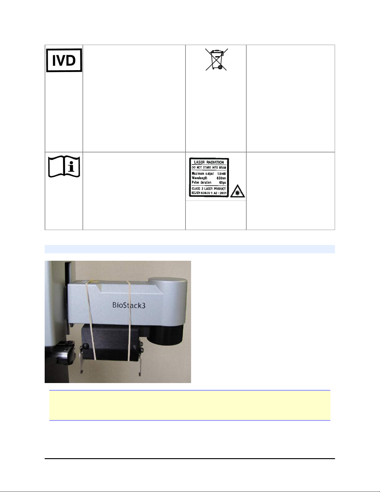
BioStack 3 and BioStack 4: Secure Gripper Before Moving
Note: Do not let the gripper flop around! Before moving the BioStack 3 or BioStack 4,
secure the gripper with a rubber band or tape to prevent it from losing its alignment. A
complex recalibration is required if it is knocked out of position.
BioStack™ Microplate Stacker
Page 23

Chapter 1
Introduction
Thank you for purchasing the BioStack™ Microplate Stacker.
This chapter describes its features and specifications and
includes important contact information.
Introducing the BioStack 2
Package Contents 6
Optional Accessories 6
Specifications 9
Page 24
2 | Chapter 1: Introduction
Introducing the BioStack
This manual covers the BioStack (BIOSTACK2WR), BioStack3 (BIOSTACK3WR),
and BioStack4 (BIOSTACK4). Unless otherwise specified, the term BioStack refers
to all models.
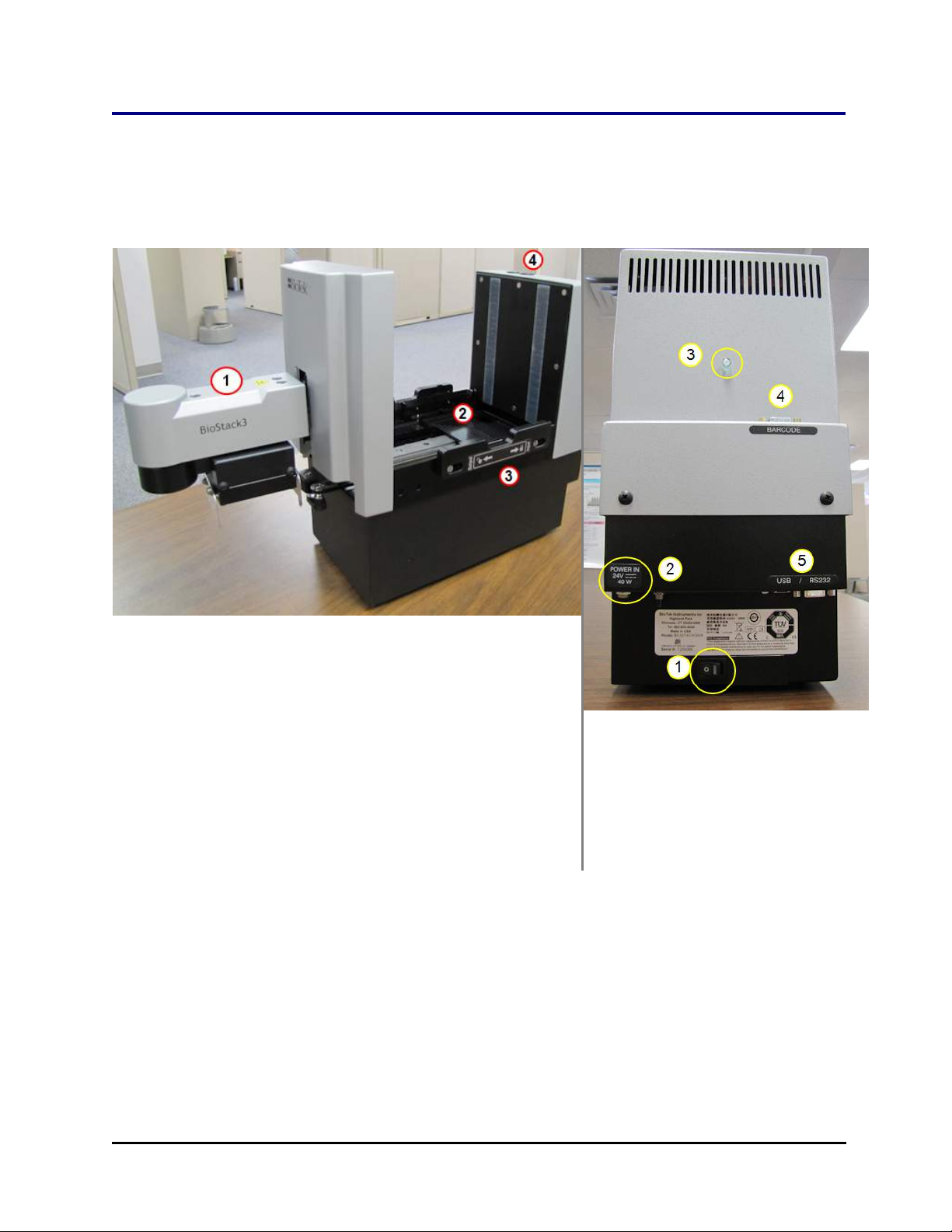
BioStack 3 shown without stacks
Side view
1. Gripper—arm with wrist and gripper
2. Plate carrier Back view
3. Stack locks 1. Power switch
4. Dip switch access 2. Power cable port
3. LED status indicator
4. Barcode scanner port
5. Computer and interfacing
instrument ports
BioStack™ Microplate Stacker
Page 25
Introducing the BioStack | 3
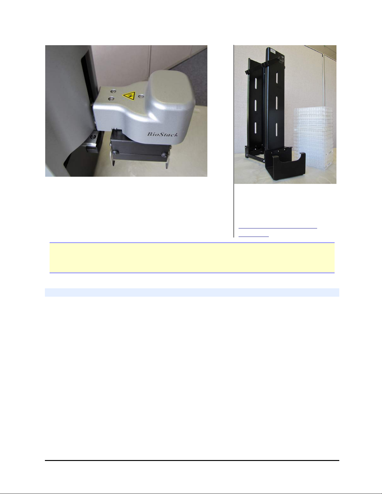
BioStack Gripper arm Stack, pedestal and plates
All current BioStack models have rotational wrists that
enable them to interface with most BioTek instruments in
the most convenient and comfortable angle/position.
A tool to help load plates into
the stack, called a pedestal, is
provided with the BioStack: See
Load Plates Using the
Pedestal on page 44.
Important: Review the Wrist Angle Setting Requirements on page 26 to determine
if you need to change the wrist angle setting to interface correctly with your BioTek reader
or liquid handler.
Product Description
The BioStack Microplate Stacker is a simple and cost-effective solution for benchtop
automation of BioTek’s microplate instrumentation. The BioStack's compatibility
with a range of detection and liquid handling systems provides laboratories high
throughput processing for a variety of applications in genomics, proteomics, drug
discovery, and clinical diagnostics. Speed, ease of use, and walk-away automation
are guaranteed for any routine microplate process.
The BioStack’s small footprint fits easily in standard laboratory hoods and may not
require a computer. As a batch processor for BioTek readers and liquid handlers,
the BioStack interfaces seamlessly with BioTek’s Gen5 Data Analysis Software and
Liquid Handling Control (LHC) Software.
Up to two BioStacks (2WR models only) can interface with the Precision Microplate
Pipetting System for unattended plate replication, bulk reagent dispensing, or other
liquid handling operations.
BioTek Instruments, Inc.
Page 26

4 | Chapter 1: Introduction
Features:
l Automates routine laboratory procedures
l 10, 30, or 50 standard height microplates per interchangeable stack
l Simple to use for all laboratory personnel
l Restacking capability
l Small footprint conserves precious benchtop space
l Universal design compatible with all supported BioTek instrumentation
l Designed for heavy use with aluminum precision-ground base and synchronistic
movement
l Linear mechanisms built around proven BioTek technology
l Quiet operation with cams activated by stepper motors
l Reliable transport with microplate gripped from below during transfers
l Onboard self-diagnostics ensures trouble-free operation
l BioStack 4 Only: Handles microplates with lids: removes the lid before plate transfer to
the attached instrument, and replaces the lid after retrieval from the instrument,
except in "stay-on lid" mode.
Models:
l PN BIOSTACK2WR: Supports 90° and 0° integrations; one plate at a time transfer.
l PN BIOSTACK3WR and BIOSTACK4: Support +90°, -90°, and 0° integrations; two
plates in motion for every transfer. BioStack 4 processes plates with or without lids.
BioStack 4: Notes about Handling Lidded Plates
The BioStack 4 functions similarly and can do everything the other BioStack models
do, and it can process microplates with lids.
l The required stacks are labeled "TALL LIDDED PLATE STACK" to process plates with
lids.
l The BioStack 4 supports standard stack types when not handling lids. (Conversely, do
not use the "tall lidded plate stacks" with BioStack 2/3 models.)
l The "tall lidded plate stack" also supports taller plates without lids; it can handle plates
up to 22 mm. (Maximum supported height of plate + lid = 23.2 mm when Stay-On Lid
Mode requirements are met.)
l Standard stacks are recommended for handling low-profile PCR plates. The BioStack 4
has been designed to better handle these plates that warp easily, but the best
performance is achieved combining the BioStack 4 with the standard stacks.
l Only 30- and 10-plate stacks are supported when processing lids. And, the stacks hold
fewer plates when lids are included: the 30-plate stack holds about 25 plates with lids
and the 10-plate stack holds approximately 8 plates with lids, depending on the plate
BioStack™ Microplate Stacker
Page 27

Introducing the BioStack | 5
and lid type and manufacturer. Another limiting factor is the total weight of the filled
plates in the stack cannot exceed 7.0 lbs (3.2 kg).
l When processing plates with lids the BioStack 4 performs several extra error-checking
movements, using its fingers to determine if the expected labware, i.e., a plate, lid, or
combination, is present. You'll observe several extra finger movements during
processing.
l
Except in Stay-On Lid Mode, lids are always
removed from the plates during processing even when the option to "Keep lids on
during read" is selected. In this case, the lid is removed briefly and replaced almost
immediately. Lid integrity is maintained: the lid removed from a plate is always the
same lid restored to the plate.
l A Plate Lid Definition file is required to process plates with lids.
n Gen5: Lid dimensions are stored in the Plate Type Database record. BioTek
updated the most commonly used plate type records with lid dimensions and
users can add more, as needed.
n LHC and touch screen liquid handlers: Several plate lid definition files are
provided to support the most common types of plates and new files can be
created. Important: A copy of the Plate Lid Definition file is attached to the
protocol for processing. The protocol no longer references the original lid
definition file, only its copy. If the original plate-lid definition file is modified,
those changes are not applied to the copies of the file attached to protocols.
n Keypad Liquid Handlers: Must use LHC to process plates with lids. Keypad
instruments can control the BioStack 4 when not processing plates with lids,
identical to BioStack 3 behavior.
l Certain plate types are not compatible with the de-lidding operation. Measure your
plate and lid type before use to verify they meet the minimum requirements:
Specifications on page 9. The BD Falcon 351172, for example, is a nonsupported
plate type.
BioTek Instruments, Inc.
Page 28
6 | Chapter 1: Introduction
Package Contents
n Part numbers and package contents are subject to change and vary according
to instrument model. Please contact BioTek Customer Care if you have any
questions.
n BioStack Microplate Stacker (PN BIOSTACK2WR, BIOSTACK3WR, BIOSTACK4)
n Power supply: 24 volt (PN 01281)
n Plate stacking pedestal (PN 7312083)
n Grease kit (PN 7110017)
n BioStack Operator’s Manual (PN 7311000) on USB flash drive (PN 7310571)
Optional Accessories
l Set of two microplate stacks
Stack Type Any BioStack
¥
BioStack 4*
30-plate 7310008‡ 1230004
10-plate 7310030 1230003
50-plate 7310539 N/A
* These stacks are required for transferring plates with lids. The 50-plate stacks can be used on the
BioStack 4 to process plates only, not plates with lids.
¥ Recommended for low-volume PCR plates.
‡ Also supports up to 44 low-profile, 1536-well plates without lids.
Note: Stack Types are named for the number of plates they can hold without lids.
When using lids, the approximate number of plates with lids the 30-plate stack holds is 25;
for the 10-plate stack, it's 8, depending on the manufacturer. Another limiting factor is
that the total weight of the filled plates in the stack cannot exceed 7.0 lbs (3.2 kg).
BioStack™ Microplate Stacker
Page 29
Optional Accessories | 7
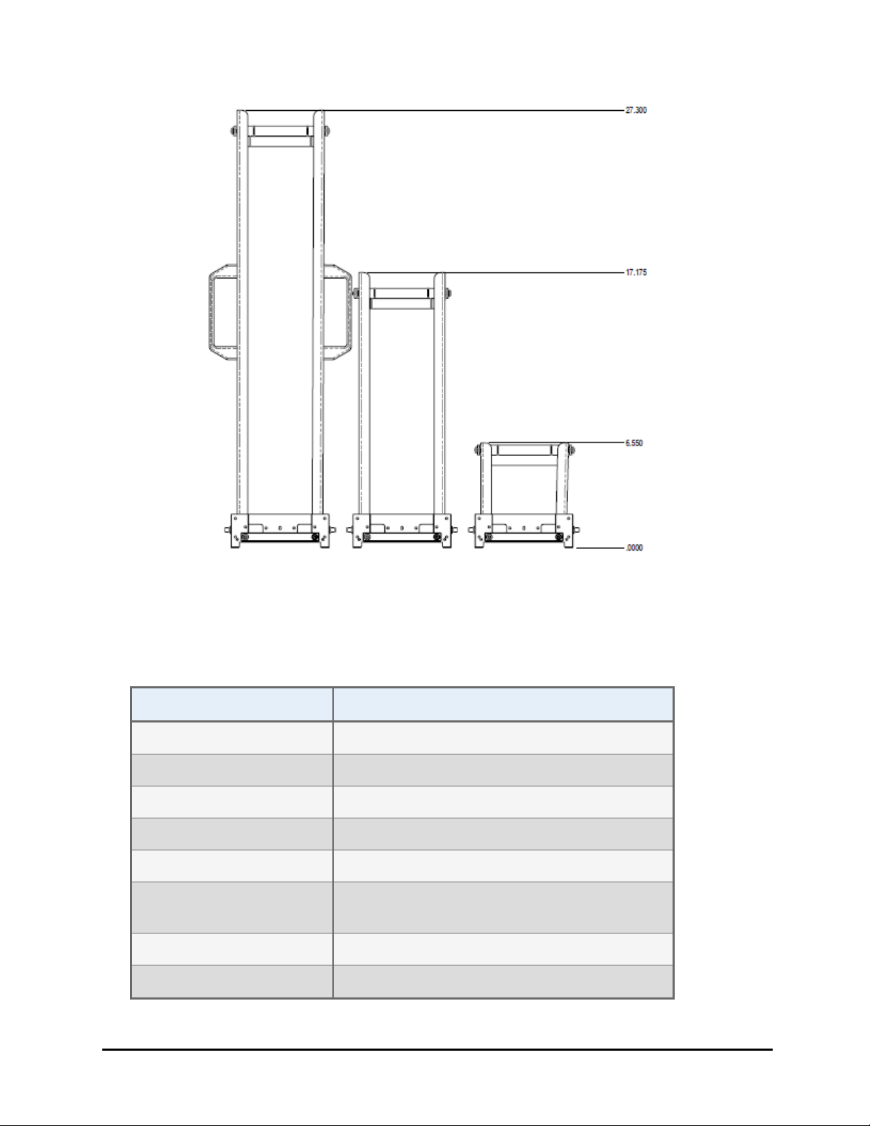
Microplate Stacks with height in inches: 50-, 30-, and 10-plate
l Instrument Qualification package (PN 7310530)
l Barcode scanner and installation kit (PN 7310017)
l Integration Kits for use with interfacing instruments:
Instrument Integration Kit
405 TS/LS PN 7310040
Cytation 1/3/5 PN 7310053
EL406 PN 7310042
ELx405 PN 7310041
Eon PN 7310049
EpochR BIOSTACK2WR: PN 7310032
BIOSTACK3WR/BIOSTACK4: PN 7310043
Epoch 2 PN 7310054
MicroFill* PN 7310012
BioTek Instruments, Inc.
Page 30

8 | Chapter 1: Introduction
Instrument Integration Kit
MicroFlo Select* PN 7310020
MultiFlo/MultiFlo FX PN 7310044
PowerWave HT
¥
PN 7310048
¥
Precision, Precision XS* PN 7110004
Synergy HT/HTX PN 7310046
Synergy 2/4/Mx/H4 PN 7310047
Synergy H1 PN 7310045
Synergy Neo and Synergy
PN 7310055
Neo2‡
*Compatible with BIOSTACK2WR only.
‡
Compatible with BioStack 4 only and uses its own barcode scanner, i.e., not compatible with the BioStack
barcode scanner listed above.
¥
Not compatible with BIOSTACK4.
BioStack™ Microplate Stacker
Page 31
Specifications
Characteristics Description
Specifications | 9
Dimensions:
Instrument only
(not including
stacks)
Weight: BIOSTACK2WR: 24 lbs (10.9 kg)
Power Supply: Compatible with 100 to 240 V~ ± 10% @50-60 Hz
Power
Consumption:
Operating
Temperature:
Humidity: Operate in a noncondensing humid environment having a maximum
BIOSTACK2WR: Length 18.5" (46.9 cm), width 7" (17.8 cm), height
14" (35.6 cm)
BIOSTACK3WR: Length 21" (54 cm), width 8" (21 cm), height 15" (38
cm)
BIOSTACK4: Length 21" (54 cm), width 8" (21 cm), height 16" (40
cm)
BIOSTACK3WR: <26 lbs (11.8 kg)
BIOSTACK4: <30 lbs (13.6 kg)
40 watts maximum
18°C to 40°C (64.4°F to 104°F)
relative humidity of 80% at temperatures up to 31° C decreasing
linearly to 50% relative humidity at 40° C.
Microplates
Running without Lids
Width: 85.48 mm (3.365") ± 0.25 mm
(0.009") at the corners
Width above flange: Min 81.0 mm; Max
Length: 127.76 mm (5.030") ± 0.25 mm
(0.015") at the corners
Max
Height:
Min approximately 10.16 mm (0.400") 7.60 mm (0.299")
14.60 mm (0.575")
22.0 mm (0.866") using BioStack 4
Lidded Plate Stacks.
Running with Lids
(BioStack 4 Only)
85.48 mm (3.365") ± 0.25 mm (0.009")
at the corners
83.2 mm
127.76 mm (5.030") ± 0.25 mm
(0.015") at the corners
Typical 96-, 384-, 1536-well plates:
16.9 mm (0.665") plate + lid combined:
plate max is 14.60 mm, except in Stay-
on Lid Mode.
BioTek Instruments, Inc.
Page 32

10 | Chapter 1: Introduction
Running without Lids
Height:
Note: The minimum plate height is a
function of the stacked height, the
plate skirt height, the plate height
dip switch setting, and the control
method. See Control Method
Limitations: on page 89.
Warp: The warp for all models complies with SLAS standards: When resting on a flat
surface, the top surface of the plate must be parallel to the resting surface
within 0.76 mm (0.0299"); except BioStack 4 supports low-profile plates with
a warp value within 2.2 mm.
Important: Less-rigid polypropylene, low-profile PCR plates must have
sealing tape applied over the entire top surface.
Max
Weight:
Maximum weight for all plates with fluid in a single stack.
12.0 lbs (5.5 kg) 7.0 lbs (3.2 kg)
Running with Lids
(BioStack 4 Only)
See Microplate and Lid Dimensions
on page 53.
The BioStack is not compatible with removable-strip-type microplates.
Lids BioStack 4 Only
Width: 85.48 mm (3.365") ± 0.50 mm (0.019") along entire edge
Length: 127.76 mm (5.030") ± 0.50 mm (0.019") along entire edge
Minimum Height: 3.5 mm (0.138")
Other requirements:
Minimum Gap: 1.25 mm (0.049") Plate short-side flange to lid
Lid on Plate: 16.9 mm (0.665") Max overall height
Plate on Lid: 23.2 mm (0.913") Max overall height
Stay-On Lid Mode (BioStack 4 Only)
When these conditions are met the BioStack 4 handles certain low-density plates
with lids. This mode offers the ability to keep the lid on the plate for the duration of
the protocol.
BioStack™ Microplate Stacker
Page 33

Minimum software versions:
l BioStack 4 basecode: PN 1230200 version 1.05 (or higher)
l Gen5: version 2.07 (or higher)
l LHC: version 2.18 (or higher)
l Note: Gen5 TS (for touch screen models) does not support stay-on lid mode.
Certain 6-, 12-, 24-, and 48well microplates with lids that
conform to ANSI/SLAS 2-2004
standard dimensions, as
specified, and with a:
l Minimum gap between plate
and lid when plate is on lid:
1.5 mm
l Maximum height of plate +
lid combined: 23.2 mm (also
called "stacked-plate-withlid" height)
Specifications | 11
Use calipers to measure the gap
between lid and plate.
Tall Lidded Plate Stacks
are required.
Uniquely designed stacks
labeled "Tall Lidded Plate
Stacks" support stay-on lid
mode and tall plate processing
without lids.
Stack Weights: PN 1230008
BioTek offers this accessory to
prevent the last plate's lid from
hanging in the stack during stayon lid mode. Better performance
was observed when using the
weights with taller-than-standard
plates without lids, as well.
Gen5 will keep the lid on the plate during processing when its plate type Lid
BioTek Instruments, Inc.
Page 34

12 | Chapter 1: Introduction
Parameters are defined to support it: Fill the checkbox in Advanced Options. Plate Type
records for Nunc 6-, 12-, 24-, and 48-well plates and lids that meet these requirements are
ready for selection, e.g., "Nunclon 24 well." You can create or modify the plate type record of
other plates that meet the requirements. Learn more in Gen5's Help.
Note: A small number of stacks
with a Lidded Plate Stacks label
were released to support stay-on
lid mode before the label was
changed to Tall Lidded
Plate Stack. The "stack dogs,"
inside and at the bottom of the
stacks, were modified to better
handle plates with external trim
or ridges. If the dogs on your
stacks match those shown here,
with shortened top lips, they can
be used for stay-on lid mode.
BioStack™ Microplate Stacker
Page 35

Chapter 2
Installation
This chapter contains instructions for setting up and
configuring the BioStack. Instructions for installing the
BioStack with the interfacing instruments are contained in
individual PDF files on the BioStack Operator’s Manual USB
Flash Drive (PN 7311067).
Upgrade Scenarios 14
Unpack and Inspect the Instrument 15
Setting Up the BioStack 17
Remove the Shipping Hardware—BIOSTACK2WR 18
Remove the Shipping Hardware—BioStack 3 20
Remove the Shipping Hardware—BioStack 4 23
Dip Switch Settings 28
Connect to Power 31
Where to Go Next 35
Repacking the BioStack 36
Install the Shipping Hardware—BioStack2WR 37
Install the Shipping Hardware—BioStack 3 37
Install the Shipping Hardware—BioStack 4 38
Page 36

14 | Chapter 2: Installation
Upgrade Scenarios
If you purchased the BioStack to interface with an existing instrument, you may
need to upgrade the hardware and/or software on that instrument. Refer to the
table below and contact BioTek TAC with any questions.
Minimum computer control software for:
PC Software BioStack 3 BioStack 4
LHC (Liquid Handling Control) 2.12 or higher 2.16 or higher
Gen5 (Data Analysis ) 2.01 or higher 2.05 or higher
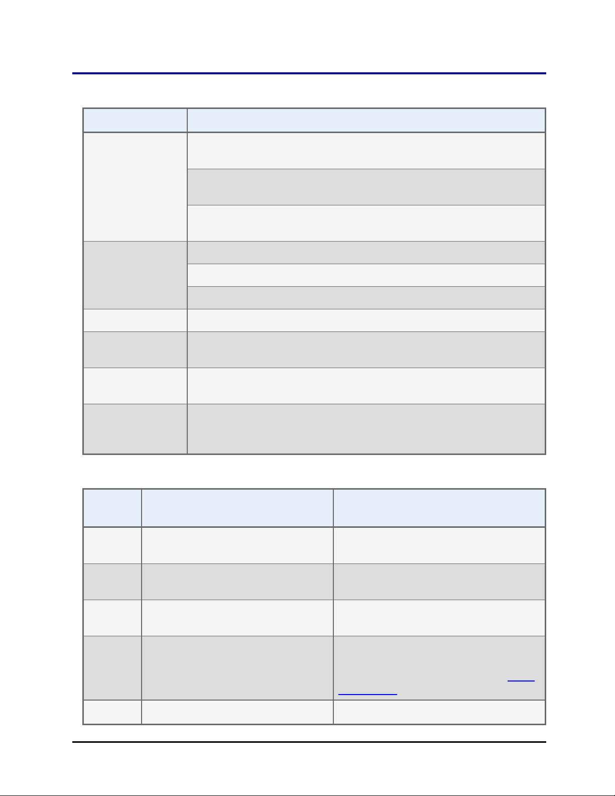
If you have: You may need:
ELx405
with Serial Number <=182187 A BioStack-compatible microplate carrier and new
basecode software (upgrade kit PN 7310006). The carrier
must be installed by authorized personnel.
with Serial Number
>=182188 and <185301
Eon
with Serial Number <1310151 Instruments with a lower serial number may not have a
Epoch
Any serial number.
Compatible instruments have a
“BioStack Ready” sticker: R
models.
MicroFill‡
with Serial Number <185105 New basecode software (upgrade kit PN 7310015).
MicroFlo Select‡
with basecode version <1.06 New basecode software.
PowerWave
with Serial Number <1310151 Instruments with a lower serial number may not have a
New basecode software (upgrade kit PN 7310013).
BioStack-compatible plate carrier. Contact BioTek TAC.
A BioStack-compatible microplate carrier, which must be
installed by authorized Service personnel. Gen5 v.2.0 is
required.
BioStack-compatible plate carrier. Contact BioTek TAC.
PowerWave HT is not compatible with BioStack4.
BioStack™ Microplate Stacker
Page 37

Unpack and Inspect the Instrument | 15
If you have: You may need:
Precision**‡
with Serial Number >=187931 Basecode software version 2.14 or greater.
Synergy HT
with Serial Number <181151 A BioStack-compatible microplate carrier and new
basecode software (upgrade kit PN 7310007). Note: The
carrier must be installed by authorized Service personnel.
‡ Not compatible with BioStack3/BioStack4.
** The following Precision Microplate Pipetting Systems are not BioStack-
compatible:
oInstruments with Serial Number < 187931,
o12-channel model
oUniversal models (PRC384U).
Unpack and Inspect the Instrument
n Save all packaging materials. If you need to ship the instrument or accessories
to BioTek for repair or replacement, you must use the original packaging. Using
other forms of commercially available packaging is not recommended and can
void the warranty. If improper packaging results in damage to the instrument
during shipping, BioTek may impose additional charges.
Inspect the shipping boxes, packaging, instrument, and accessories for signs of
damage.
If the BioStack is damaged, notify the carrier and your BioTek representative. Keep
the shipping cartons and packing material for the carrier’s inspection. BioTek will
arrange for repair or replacement of your instrument immediately, before the
shipping-related claim is settled.
Unpack the boxes containing the instrument and other equipment:
l BioStack
l Microplate Stacks
l Barcode scanner (optional).
Remove the Shipping Panel
Tools: flat screwdriver
BioTek Instruments, Inc.
Page 38

16 | Chapter 2: Installation
1. Grasp the handles on the shipping panel to lift the instrument from the inner
box.
2. Gently lay the BioStack on its side on the work surface, so the panel hangs over
the edge.
3. Remove the screws and washers that attach the shipping panel to the instrument.
4. Save the panel and all packing materials for possible future reshipment.
BioStack™ Microplate Stacker
Page 39

Setting Up the BioStack | 17
Setting Up the BioStack
Important: Avoid excessive humidity. Condensation directly on the sensitive
electronic circuits can cause the instrument to fail internal self-checks.
Install the instrument on a level, stable surface in an area where temperatures
between 18°C (64°F) and 40°C (104°F) can be maintained.
Avoid:
l Excessive humidity: Condensation directly on the sensitive electronic
circuits can cause the instrument to fail internal self-checks. Operate in a
noncondensing humid environment having a maximum relative humidity
of 80% at temperatures up to 31° C decreasing linearly to 50% relative
humidity at 40° C.
l Dust: Efficient microplate transporting may be affected by extraneous
particles (such as dust) on the carrier’s linear ways. A clean work area is
necessary to ensure smooth plate transporting.
BioTek Instruments, Inc.
Page 40

18 | Chapter 2: Installation
Remove the Shipping Hardware—BIOSTACK2WR
Warning: Remove the shipping hardware before turning on the BioStack.
Tools: You need a standard screwdriver, a small Phillips-head screwdriver, and
3/32" hex wrench.
Shipping hardware in the BioStack's interior (BIOSTACK2WR)
1. Locate and remove the shipping block and four mounting screws inside the
BioStack.
2. Remove the carrier shipping screw.
3. Remove the gripper shipping screw.
BioStack™ Microplate Stacker
Page 41

Remove the Shipping Hardware—BIOSTACK2WR | 19
Wrist/gripper cover removed exposing small wrist shipping bracket
4. Remove the gripper cover (with the BioStack label) using the Phillips
screwdriver to expose the small wrist shipping block.
5. Use the 3/32 hex wrench to remove the wrist shipping block.
6. Reinstall the wrist/gripper cover.
7. Store the screws with the other packaging materials in the shipping boxes.
BioTek Instruments, Inc.
Page 42
20 | Chapter 2: Installation
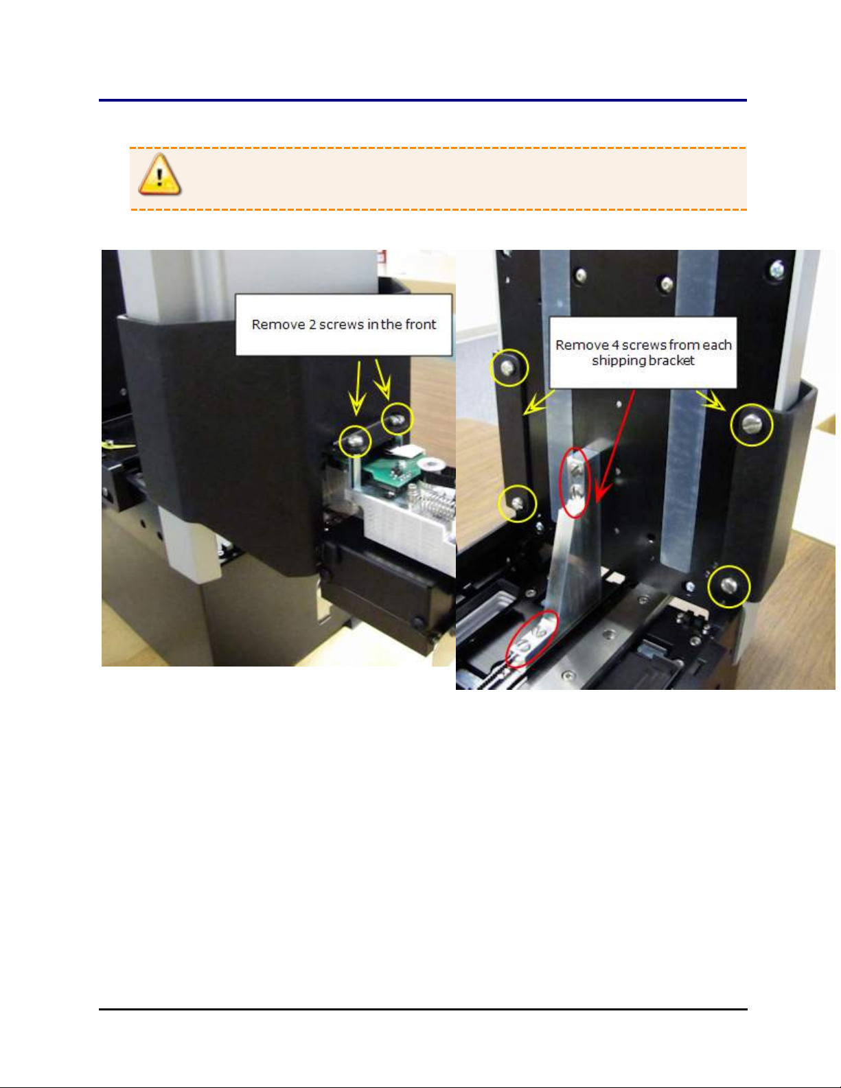
Remove the Shipping Hardware—BioStack 3
Warning: Remove the shipping hardware before turning on the BioStack.
Tools: You need a standard screwdriver and a small Phillips-head screwdriver.
One shipping bracket wraps around the front Another shipping block sits inside
1. Remove the two screws from the front of the instrument.
2. Remove the remaining 4 screws inside that hold the bracket onto the instrument.
Carefully remove the bracket.
3. Locate and remove the shipping block and four mounting screws inside the
BioStack.
BioStack™ Microplate Stacker
Page 43
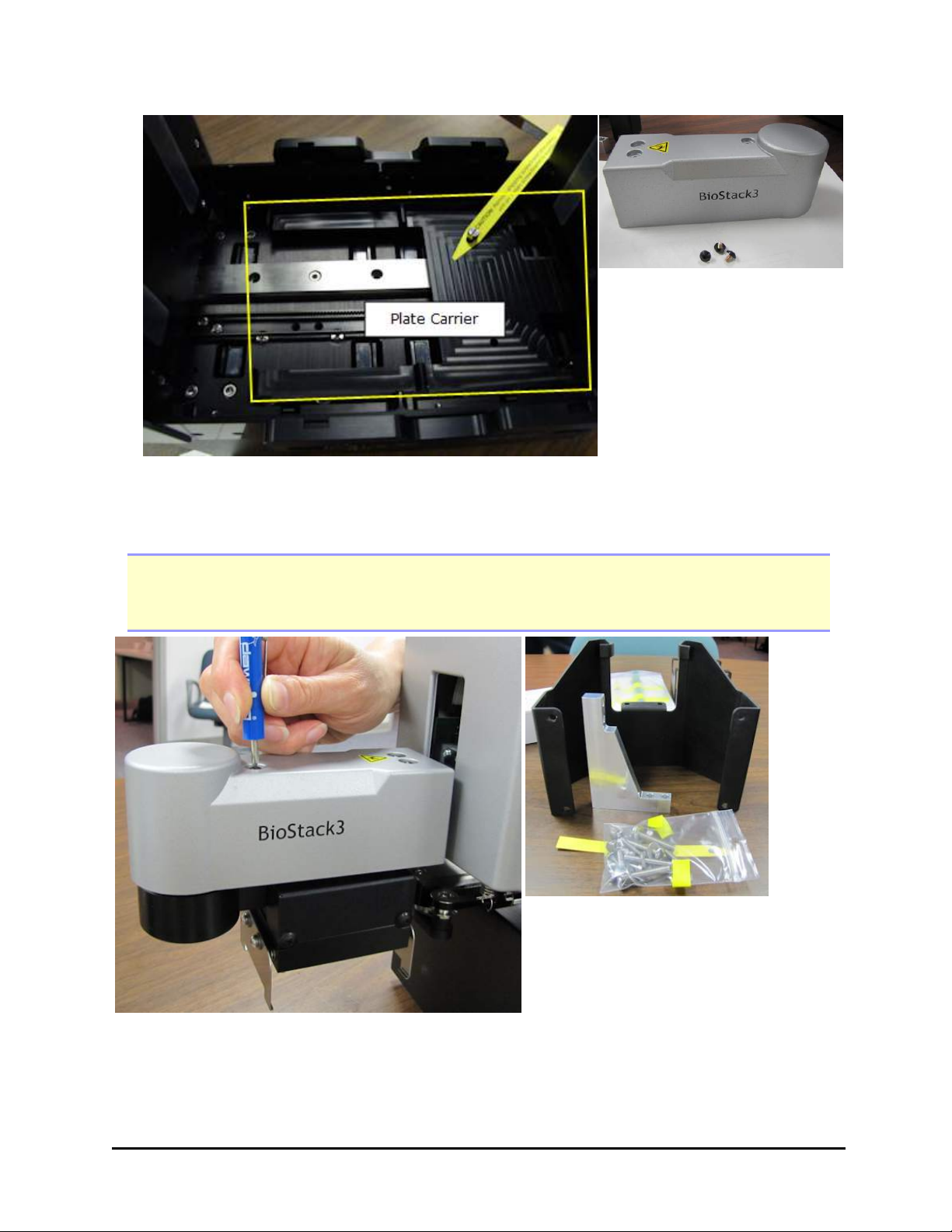
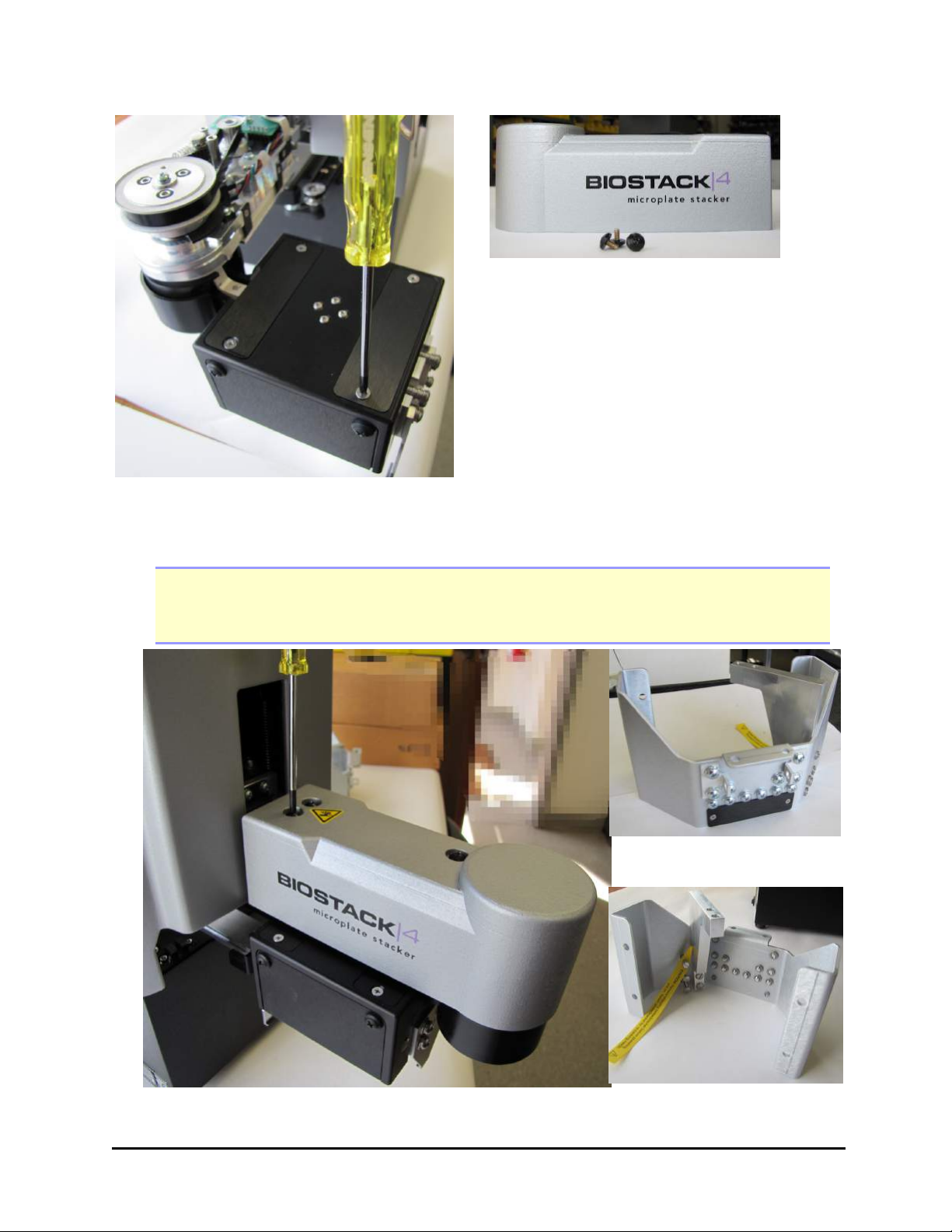
4. Remove the plate carrier shipping screw.
Remove the Shipping Hardware—BioStack 3 | 21
Gripper arm cover and screws
5. Remove the rubber band that holds the rotational wrist secure.
Note: Do not let the gripper flop around! Before moving the BioStack 3 or BioStack 4,
secure the gripper with a rubber band or tape to prevent it from losing its alignment. A
complex recalibration is required if it is knocked out of position.
Save the shipping hardware
Installing the gripper arm cover
6. Locate and install the gripper arm cover using the small Phillips-head
screwdriver.
BioTek Instruments, Inc.
Page 44

22 | Chapter 2: Installation
7. Store all the shipping hardware and screws with the other packaging materials in
the shipping boxes and keep for future use.
BioStack™ Microplate Stacker
Page 45
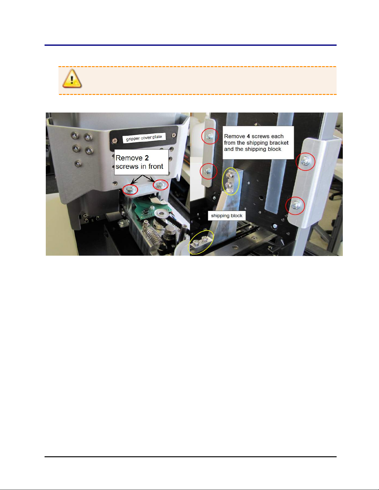
Remove the Shipping Hardware—BioStack 4 | 23
Remove the Shipping Hardware—BioStack 4
Warning: Remove the shipping hardware before turning on the BioStack.
Tools: You need a standard screwdriver and a small Phillips-head screwdriver.
One shipping bracket wraps around the front and attaches to the inside. A shipping block sits inside.
1. Remove the two screws from the front of the instrument.
2. Remove the remaining 4 screws inside that hold the bracket onto the instrument.
Carefully remove the bracket.
3. Remove the shipping block and four mounting screws inside the BioStack.
4. Remove the small, black cover plate that is stored on the shipping bracket. (See
picture below.)
BioTek Instruments, Inc.
Page 46
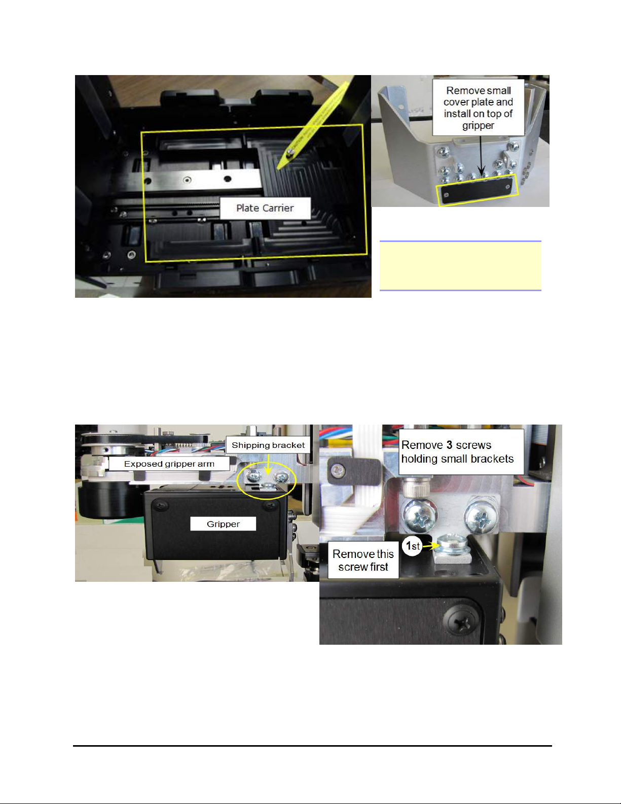
24 | Chapter 2: Installation
Remove the gripper cover plate
Note: Screw the screws into
the shipping bracket for
storage.
5. Remove the plate carrier shipping screw.
6. Returning to the front of the BioStack, remove the rubber band that holds the
rotational wrist secure.
7. Remove the small shipping brackets on each side of the wrist that hold the
gripper steady. On both sides, first remove the screw from the gripper itself,
then remove the two screws from the gripper arm.
BioStack™ Microplate Stacker
Page 47
Remove the Shipping Hardware—BioStack 4 | 25
Gripper Arm Cover
8. Install the small cover plate you removed from the shipping bracket on top of
the gripper, using the small Phillips-head screwdriver.
Note: Do not let the gripper flop around! Before moving the BioStack 3 or BioStack 4,
secure the gripper with a rubber band or tape to prevent it from losing its alignment.
A complex recalibration is required if it is knocked out of position.
Save the shipping hardware
Installing the gripper arm cover
BioTek Instruments, Inc.
Page 48

26 | Chapter 2: Installation
9. Locate and install the gripper arm cover using the small Phillips-head
screwdriver.
10. For safekeeping, screw all the screws and washers, the small shipping brackets
and the large shipping block onto the large shipping bracket. Store the shipping
hardware with all the other packaging materials in the shipping boxes and keep
for future use.
Wrist Angle Setting Requirements
Each instrument requires the BioStack to have a certain wrist angle setting:
l The BIOSTACK2WR ships with the wrist angle set to 90°; its other setting is 0°.
l The BIOSTACK3WR/BIOSTACK4 ships with the wrist angle set to +90°; its other
settings are 0° and -90°.
Instrument BIOSTACK2WR BIOSTACK3WR/BIOSTACK4
Liquid Handlers
405 TS, 405 LS* 90° +90°
EL406, ELx405* 90° +90°
MicroFlo Select* 90° N/A
MultiFlo, MultiFlo FX* 90° +90°
Precision/XS, MicroFill 0° N/A
Readers
Cytation 1, 3, 5 N/A +90°
Eon 0° 0°
EpochR 0° -90°
Epoch 2 90° +90°
PowerWave HT 90° +90°
Synergy H1 90° +90°
Synergy 2, 4, MX, HT,
HTX, H4
0° -90°
Synergy Neo/Synergy
Neo2
BioStack™ Microplate Stacker
N/A 0° (BioStack4 Only)
Page 49

Remove the Shipping Hardware—BioStack 4 | 27
* 0° orientation (front-facing integration) is possible with these liquid handlers and
the BIOSTACK2WR. See 0 Degree Orientation for Liquid Handlers below.
If your instrument requires a wrist angle other than the default (shipped) setting
you must follow the procedure: Change Setting for Wrist Angle on page 29
The wrist angle designates the position of the gripper:
-90° angle +90° angle 0° angle
clockwise counterclockwise no rotation
When viewed from above, the +90° angle setting turns the wrist counterclockwise,
the -90° turns the wrist clockwise, and the 0° angle does not turn the wrist.
n Always put the barcode scanner on the opposite side of the gripper's position.
+90°/90° put scanner on right side; -90 put the scanner on the left side of the
instrument as you are facing it.
0 Degree Orientation for Liquid Handlers
Most BioTek liquid handlers can interface with the BIOSTACK2WR in a front-facing
or 0° orientation. This may be necessary to fit both the instrument and the BioStack
in a safety hood, for example. Or when bench space is limited.
n This option is not supported with BioStack 3 or BioStack 4.
Change the dipswitch setting as described below. Attach the BioStack aligning plate
to the instrument's aligning plate in the front holes provided, as shown here:
BioTek Instruments, Inc.
Page 50

28 | Chapter 2: Installation
0° Integration Position
Dip Switch Settings
Two sets of dip switches on the BioStack control variable options, e.g., to change the
wrist angle, use 50-plate stacks, or install the barcode scanner.
Dip switch 1 and 2
Two arrays of dip switches, switch 1:
SW1 and switch 2: SW2. On each switch,
note the sequence, from right to left, of
the four switches.
Closed = toward board; Open = away from
board. All SW1 switches are closed in the
photo above.
Back of the BioStack showing dip switch access
openings: 1 and 2.
BioStack™ Microplate Stacker
Page 51

Dip Switch Settings | 29
Warning: Do not change a switch setting unless explicitly instructed to do so.
Switch 1 All Models
SW1 - 1 Plate Height: Closed = Normal, standard plates; Open = for low-profile
plates.
SW1 - 2 Do Not Change! 2WR = Closed, 3WR = Open.
SW1 - 3 Barcode Scanner: Closed = Not installed; Open = Installed.
SW1 - 4 Closed: Do Not Change!
Switch
2
SW2 - 1 Closed = for 10 or 30 plate stacks; Open = for 50 plate stacks
SW2 - 2 Closed: Do Not Change! Closed: Do Not Change!
SW2 - 3 Wrist Angle: Open = 90°;
SW2 - 4 Closed: Do Not Change! SW2-3 Open and SW2-4 Closed = +90° Wrist
SW2-3 Closed and SW2-4 Closed = -90°
BIOSTACK2WR BIOSTACK3WR/BIOSTACK4
SW2-3 Closed and SW2-4 Open = 0° Wrist
Closed = 0°
Angle
Angle
Wrist Angle
Change Setting for Wrist Angle
Most BioTek instruments require the BioStack wrist to be set at a specific angle.
Follow these instructions to change the wrist angle dip switch setting for your
instrument.
See Wrist Angle Setting Requirements on page 26
1. Turn off the BioStack.
2. Two plugs on the rear wall of the instrument cover two sets of dip switches.
Remove plug #2, the plug on the right when viewing the instrument from the
rear.
3. Using a pencil tip, change the switch settings to suit your instrument:
BioTek Instruments, Inc.
Page 52

30 | Chapter 2: Installation
Switch 2
Wrist Angle BIOSTACK2WR BIOSTACK3WR/BIOSTACK4
90°/+90° SW2 - 3 = Open SW2-3 Open and SW2-4 Closed
0° SW2 - 3 = Closed SW2-3 Closed and SW2-4 Open
-90° N/A SW2-3 Closed and SW2-4 Closed
4. Replace the plug.
Change Setting for 50-Plate Stacks
For better performance when using 50-plate stacks and routinely processing more
than 30 plates, change the dip switch setting. This changes the BioStack's behavior to
better handle the heavier load.
1. Turn off the BioStack.
2. Two plugs on the rear wall of the instrument cover two sets of dip switches.
Remove plug #2, the plug on the right when viewing the instrument from the
rear.
3. Using a pencil tip, push SW-2 switch #1 (the right-most dip switch) to its Open
position, away from the instrument.
4. Replace the plug.
Test Plates for Compatibility—BioStack 4 Only
Perform this simple test to make sure your microplates are compatible with the
BioStack 4:
BioStack™ Microplate Stacker
Page 53

Connect to Power | 31
1. Turn off and unplug the BioStack, if necessary. Raise the gripper and move its
wrist out of the way.
2. Expose the BioStack's plate carrier: slip your hand inside the front of the
BioStack under the gripper, feel for the outer edge of the plate carrier and gently
pull it out.
3. Put one of your microplates on the carrier and slide it around a bit to make sure
there is at least some room around the plate, i.e., enough space to move the
plate.
If the plate fits too snugly in the carrier, you can loosen screws in the side of the
carrier to give the plate more room: See Loosen Plate Carrier Set Screws -
BioStack 4 Only on page 90.
Strongly recommended: Measure your plate and lid type to verify they meet the
minimum requirements before use: See Specifications on page 9. Some plate types are
not compatible.
Connect to Power
Warning! Power Rating. The BioStack must be connected to a power
receptacle that provides voltage and current within the specified rating for the system.
Use of an incompatible power receptacle may produce electrical shock and fire hazards.
Warning! Electrical Grounding. Never use a plug adapter to connect primary
power to the BioStack. Use of an adapter disconnects the utility ground, creating a
severe shock hazard. Always connect the system power cord directly to an appropriate
receptacle with a functional ground.
The BioStack supports voltage in the range of 100–240 V~ at 50–60 Hz.
1. Connect the power cable to the power supply.
2. Plug the cable into the power socket in the rear panel of the BioStack. Tighten
the knurled nut.
3. Insert the three-prong plug into an appropriate receptacle.
BioTek Instruments, Inc.
Page 54

32 | Chapter 2: Installation
Connect to Computer
For Gen5 and LHC users
Note: See Connect to Liquid Handler on the facing page if you are not controlling
your washer/dispenser with BioTek's LHC software.
Epoch 2T and EPOCH2TC models with onboard Gen5 TS: connect the
BioStack directly to the reader (rather than an external computer, if
desired). Use the USB cable provided with the BioStack, then follow Gen5
TS instructions below, to control the BioStack with the touch screen.
(Find the USB port in the top left corner of the Epoch 2's rear panel. Only
one device can be connected at a time.)
When operating the BioStack with a reader (except touch screen instruments) or with
a liquid handler being controlled by LHC (BioTek's Liquid Handling Control
software), connect the BioStack to the host computer:
1. Use the USB or serial cable to connect the BioStack to the computer.
l If using a USB cable, and you have not already done so, follow the
instructions to install the USB Virtual COM Driver Software and to identify
the COMport. (Skip this step for the EPOCH2T and EPOCH2TC models.)
2. Turn on the BioStack and Test Communication between the BioStack and the
computer:
LHC Gen5/Gen5 TS
1. Select System>Instrument
Configuration>Add Stacker.
2. Select the Com Port and click Test
Comm.
If you have two readers set up in Gen5, select the
checkbox to tell one to Use the stacker.
Select the BioStack checkbox and specify
its COM port . Click the Test
Communication link.
Refer to Gen5's Help and the instrumentspecific instructions provided.
BioStack™ Microplate Stacker
Page 55

Connect to Power | 33
l If the test passes, return to the main view.
l If the test fails, check the cable connection to the BioStack or try a different
port. Contact BioTek TAC if problems persist.
Connect to Liquid Handler
Warning! Keep your hands away from the BioStack's gripper and microplate
carrier while the instruments are powering up.
To control the BioStack with the washer or dispenser, rather than LHC:
1. Turn off both instruments.
2. Plug in the serial cable supplied to connect the two instruments. Tighten the
securing screws.
3. BIOSTACK2WR: If the gripper is resting on the interfacing instrument's plate
carrier, manually raise it above the carrier.
4. Turn on the BioStack (the power switch is located on the rear panel). The
BioStack will home all axes (gripper, carrier, input and output stack lifts) and
perform a System Test.
l If the System Test passes, the LED status light on the rear panel will turn
on and flash until the power-up process is complete (approximately 20
seconds), then it will remain on.
l If the System Test fails, the LED status light will flash repeatedly. If this
happens, turn off the BioStack. Make sure there is no plate on the carrier,
and check for any obstructions. Ensure that all of the shipping hardware
has been removed. If you cannot resolve the problem, contact BioTek’s
Technical Assistance Center.
Configure the Liquid Handler to Control the BioStack
Note: The keypad instructions may vary slightly for your washer or dispenser. Refer to its
operating manual, if needed, for more precise instructions.
1. Turn on the washer/dispenser and allow its System Test to complete.
2. Press the Setup Menu key.
3.
Select g, BIOSTK > CONF.
4. Select BIOSTACK.
BioTek Instruments, Inc.
Page 56

34 | Chapter 2: Installation
5. When RE-STACK? appears, select YES.
6. Press the Main Menu key.
405 TS and MultiFlo FX (Touch Screen Instruments) Only
Enable the BioStack to operate with the washer/dispenser:
1. Turn on the washer/dispenser and allow its System Test to complete.
2. At the Home screen, select Instrument > Next > BioStack.
3. Select the BioStack checkbox to show it is installed.
4. Press Get Basecode Version to ensure the instruments are communicating. If
you get an error message, check the cabling and restart both instruments.
Test Communication
n (Optional) Use the Software Data Sheet on page 30 to record software version
and checksum information.
n If software version/checksum information is displayed without error, the
Communication Tests completed successfully.
Keypad: From the main menu, select UTILS > TESTS > CHKSUM/SOFTWARE >
BIOSTACK.
Touch screen: At the Home screen, select Instrument > Next > BioStack
Communication is successful if the BioStack basecode software version (the first
number), interface definition version (the second number), and checksum are
displayed.
If communication is not successful, look up the error code: Communication Error
Codes on page 74. Contact BioTek if you cannot resolve the problem.
BioStack™ Microplate Stacker
Page 57

Where to Go Next
To See
Where to Go Next | 35
Install the BioStack
with an interfacing
instrument
Install the barcode
scanner (if purchased)
Operate the BioStack The Operation chapter beginning on page 41
Maintain the BioStack The Maintenance chapter beginning on page 59 for cleaning and
Qualify the BioStack The Qualification chapter beginning on page 69 for recommended
Interpret error codes
or resolve problems
The instrument-specific PDF files for alignment instructions
The Barcode Scanner section beginning on page 93
decontamination instructions
procedures to qualify the initial and ongoing performance of the
BioStack
The Troubleshooting chapter beginning on page 73
BioTek Instruments, Inc.
Page 58

36 | Chapter 2: Installation
Repacking the BioStack
Prior to sending your instrument to us for repair, log into the Customer Resource
Center (www.biotek.com) to submit a Service Request for a Service Call Notice
(SCN) number. Your instrument's serial number is needed to process an SCN.
n Decontaminate the instrument before returning it: See Decontamination
n Failure to comply with the following instructions will void the instrument’s
warranty and result in additional charges if the instrument is damaged.
If you have lost the original packing materials, contact BioTek TACto order:
l BIOSTACK2WR: PN 7310014
l BIOSTACK3WR: PN 1160003
l BIOSTACK4: PN 1230007
n The instrument’s packaging design is subject to change. If these instructions do
not apply to the packaging materials you are using, please contact BioTek’s
Technical Assistance Center for guidance.
n If the packaging materials have been damaged, lost, or used more than four
times, contact BioTek to order replacements: PN 7310014 for BIOSTACK2WR;
PN 1163003 for the BIOSTACK3WR; PN 7313007 for the 10-plate stacks; PN
7313001 for the 30-plate stacks; PN 7313006 for the 50-plate stacks.
l The microplate stacks do not need to be returned with the instrument
unless a problem has occurred with plates in the stacks.
l The barcode scanner does not need to be returned with the instrument
unless a problem has occurred with the scanner. Remove the scanner
before repacking the BioStack.
Obtain a Work Order Number:
l Contact BioTek TAC to obtain a work order number
l Include the work order number in the shipping address label:
BioTek Instruments, Inc.
ATTN: work order number xxxxx
15 Tigan Street
Winooski, Vermont 05404 USA
BioStack™ Microplate Stacker
Page 59
Install the Shipping Hardware—BioStack2WR | 37
Install the Shipping Hardware—BioStack2WR
Reverse the process of uninstalling the shipping hardware. Refer to photos on
page 18.
Tools: You need a standard screwdriver, a small Phillips-head screwdriver and
3/32" hex wrench.
1. Turn on the BioStack to keep the gripper arm in its highest position.
n If the BioStack cannot be turned on, manually raise the gripper to its full height
and hold it there.
2. Install the gripper shipping screw (see below).
3. Remove the gripper arm cover and install the wrist shipping block using the
hex wrench.
4. Replace the gripper arm cover.
5. Install the shipping block inside the instrument.
6. Install the plate carrier shipping screw.
Next step: Repacking—Install Shipping Panel on page 39.
Install the Shipping Hardware—BioStack 3
Reverse the process of uninstalling the shipping hardware. Refer to the photos
on page 20.
Tools: You need a standard screwdriver and a small Phillips-head screwdriver.
1. Turn off the BioStack and
unplug the power cable.
2. Remove the gripper arm
cover. Place the screws in
the plastic bag (#98170) and
put the bag inside of the
arm cover. Put the arm
cover with the screws into
the bubble bag (#91083).
BioTek Instruments, Inc.
Page 60
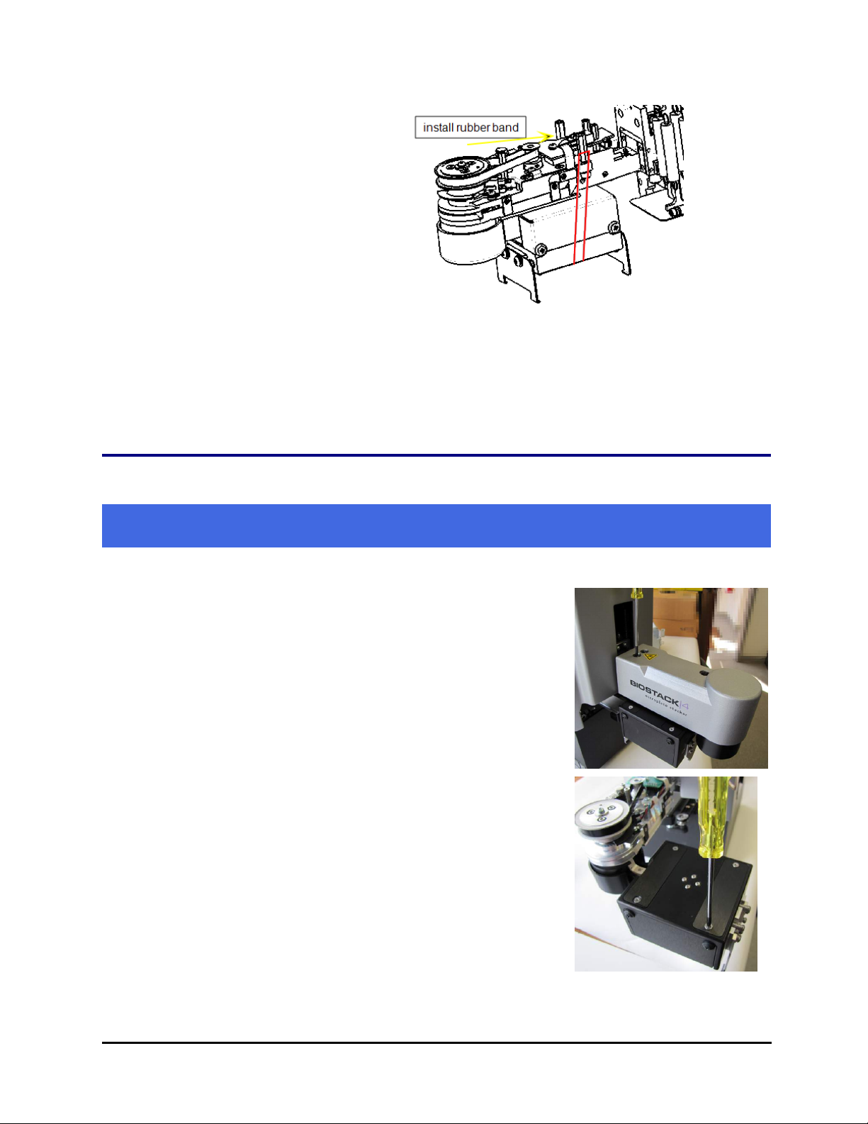
38 | Chapter 2: Installation
3. When the cover is removed,
wrap the wrist with a
rubber band to secure it for
shipping. Loop the rubber
band around posts on either
side of the wrist.
4. Install the shipping block
inside the BioStack and the
plate carrier screw.
5. Install the large shipping
bracket that wraps around
the front.
Next step: Repacking—Install Shipping Panel on the facing page.
Install the Shipping Hardware—BioStack 4
Reverse the process of uninstalling the shipping hardware. Refer to the photos
on page 23.
Tools: You need a standard screwdriver and a small Phillips-head screwdriver.
1. Turn off the BioStack and unplug the power cable.
2. Remove the gripper arm cover. Place the screws in the
plastic bag (#98170) and put the bag inside of the arm
cover. Put the arm cover with the screws into the
bubble bag (#91083).
3. Remove the small cover plate from the top of the
gripper using the small Phillips-head screwdriver.
This exposes the holes for installing the two small
shipping brackets.
4. Attach the cover plate to the large shipping bracket for
safekeeping.
5. Install the small shipping brackets on both sides of the
gripper: first install the screw into the gripper, then
the two screws into the gripper arm.
BioStack™ Microplate Stacker
Page 61
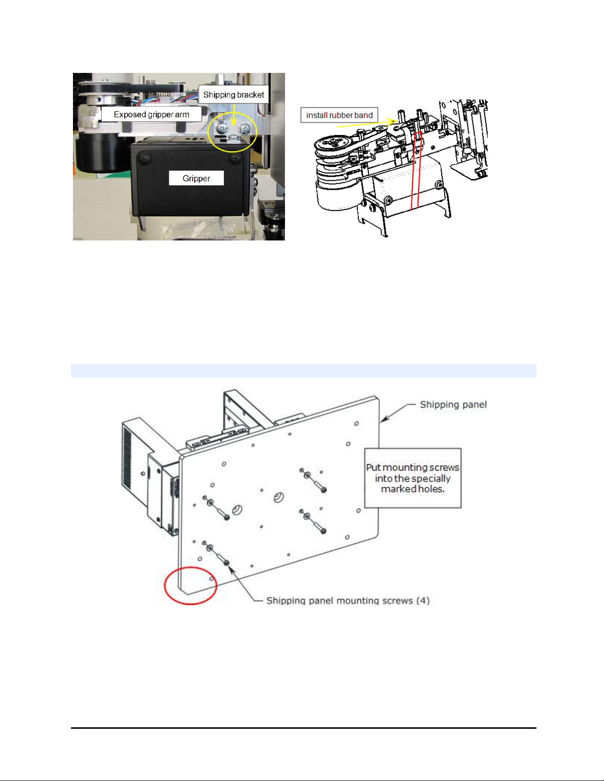
Install the Shipping Hardware—BioStack 4 | 39
6. Wrap the wrist with a rubber band to secure it for shipping. Loop the rubber
band around posts on either side of the wrist.
7. Install the shipping block inside the BioStack and the plate carrier screw.
8. Install the large shipping bracket that wraps around the front.
Next step: Repacking—Install Shipping Panel below.
Repacking—Install Shipping Panel
Shipping panel in the proper orientation—notch in left-bottom corner
1. Carefully lay the BioStack on its side, with the bottom facing you and flush
against the edge of the work surface.
2. If applicable, remove the four aligning posts/legs. Keep the posts with the
accessories package.
BioTek Instruments, Inc.
Page 62

40 | Chapter 2: Installation
3. Install the shipping panel with the accompanying mounting screws and
washers. (Note the orientation of the panel to the instrument.)
4. Lift the instrument until it is resting upright on the work surface.
5. Grasp the shipping handles and carefully lower the BioStack into the inner
shipping box. Lower the inner sleeve into the inner shipping box.
BIOSTACK2WR: Place the gripper arm cover in its bubble bag. Put the various
accessories, power supply, and so on into one of the side compartments of the
inner sleeve.
6. Put the corner blocks on the inner shipping box and put it into the outer
shipping box. Tape the box closed.
7. Write the work order number in large, clear letters on the outside of the box.
Ship the box to BioTek.
BioStack™ Microplate Stacker
Page 63

Chapter 3
Operation
This chapter provides instructions for controlling the BioStack.
Before You Start 42
Load Plates into Input Stack 43
Processing Microplates 46
Processing Plates with Lids 49
Page 64

42 | Chapter 3: Operation
Before You Start
If you have not already done so:
l Install the BioStack with the interfacing instrument using the instrument-specific
instructions provided.
l If the instruments have been moved since installation, perform the Verify Test to re-
verify alignment.
l Install the interfacing instrument’s components according to the instructions in its
operator’s manual.
n Always do a practice run to make sure the BioStack properly delivers and
retrieves plates from the interfacing instrument before doing an actual run.
n Never remove the plate stacks during operation.
BioStack™ Microplate Stacker
Page 65

Load Plates into Input Stack | 43
Load Plates into Input Stack
n When loading plates into the input stack, be sure to orient the plates to match
the expected placement of well A1 on the interfacing instrument’s carrier.
n Make sure the plates are not overfilled, or the plates may stick together and
not separate for processing.
Important: Beware of condensation forming on lids. Do not process plates with lids when
the application causes condensation on the lids: the condensate may drip and contaminate
the plate, which could lead to false results. Review these guidelines: Prevent
Condensation on Plate Lids on page 51.
Practice loading a few empty plates into the stack to get comfortable with the process.
Before starting a program with the BioStack, load the microplates into the input
stack. To make it easier, use the supplied plate-stacking pedestal (PN 7312083).
When finished, refer to the labels on the stack locks for stack placement and the
direction arrows at the top of the stacks for orientation.
Stack Lock: identifies the Input and Output stack
locations
Slide to lock the stacks in place. Make sure the stack label
points toward the gripper.
Special stacks labeled
"TALL LIDDED PLATE
STACK" are required to
process plates with lids
(and plates taller than 14.6
mm without lids).
BioStack Barcode Scanner: use plates with flat, vertical sidewalls to ensure the
labels will lie flat upon the surface. See Preparing and Attaching Barcode Labels
on page 99.
BioTek Instruments, Inc.
Page 66

44 | Chapter 3: Operation
Load Plates Using the Pedestal
BioTek provides a handy tool for
loading plates into and removing
them from a stack.
The pedestal, PN 7312083, gives you
better access to the plates when
loading the stack, helping to ensure
they sit properly and evenly.
n When loading the maximum number of
plates supported by the stack onto the
pedestal, the top few plates may rise
above the top of the stack. They will
lower into the correct position when the
stack is lifted.
Reverse the procedure to empty a stack: Put
the full stack on top of the pedestal to give
yourself a hand-hold to lift out the plates.
Step 1:
Put the empty stack on top of the
pedestal.
BioStack™ Microplate Stacker
Step 2:
Load the plates into the stack on top of
pedestal.
Step 3:
Lift the stack up and off the
pedestal.
Page 67

Load Plates into Input Stack | 45
Supported Microplate Types and Dimensions
See also Specifications on page 9.
Microplates must be stackable and of single-piece construction. Do not use
removable-strip-type plates.
A: Length: 127.76 mm ± 0.25 mm
B: Width: 85.48 mm ± 0.25 mm
F: Plate Height: ~10.16 mm to 14.60 mm (exception for stay-on lide mode)
Nesting: The microplates must nest with
each other. Plates with ribs or other
small, sharp edges on their base may not
stack well and may “catch” when moving
down the stack. Plastic burrs (extra
plastic) on the edges of plates may also
cause problems.
Stacked height is the plate height minus the base recess. Most plates have a base recess of
1.0 mm and a skirt height of 2.4 mm, 6.1 mm, or 7.6 mm.
See Plate Stacked Height on page 88.
BioTek Instruments, Inc.
Page 68

46 | Chapter 3: Operation
n Less-rigid polypropylene, low-profile PCR plates must have sealing tape applied
over the entire top surface. BioStack 4 is designed to better handle plate
warping than other models, nevertheless, these plates may cause problems,
especially after thermocycling.
Do your plates nest easily?
Perform this test to determine whether a particular brand of plates will nest easily:
Stack one plate on top of another and then check to see if the top plate is slightly (1
mm or 1/16") off to the side or front-to-back. If this is the case, the plates may catch
when moving down the stack.
Processing Microplates
After aligning the BioStack's gripper with the instrument's plate carrier, you can
begin processing microplates:
l Load Plates into Input Stack on page 43
l
Load Plates Using the Pedestal on page 44
l Lock the stacks: Slide the stack locks after loading the input and output
stacks.
l Consider whether to Restack the Plates on page 49
l Review Processing Plates with Lids on page 49, if applicable
l Start Up the BioStack on page 57
Controlling the BioStack:
Keypad Control
(liquid handlers only)
When controlling the BioStack with the
instrument's keypad, plates are automatically
transferred whenever a protocol other than a
maintenance or priming protocol is run.
Make sure the washer/dispenser is configured
for BioStack operation: Connect to Liquid
Handler on page 33.
Computer Control
Review instructions in the software's Help
system to tell the BioStack when to transfer
microplates.
When using one computer to control multiple
instruments, open two sessions of the
software, one for each instrument.
405 TS and MultiFlo FX touch screen instruments
You must create a BioStack-specific protocol. Refer to the instrument-specific
instructions about operating with the BioStack.
BioStack™ Microplate Stacker
Page 69

Processing Microplates | 47
LHC
You must create a protocol that includes BioStack start and end steps. Find step-bystep instructions for creating protocols in the LHCHelp.
Gen5/Gen5 TS (touch screen)
After setup, Gen5 presents a dedicated Stacker Automation screen for reading the
microplates in the input stack.
You can choose to read a certain number of plates or the whole stack and, if
applicable, scan barcodes and control long-term kinetic experiments. The Stacker
Automation screen also provides a control to "Restack the plates."
When an initial run has been completed, you can "Add Plates" to the experiment
(and the input stack) and continue processing using the stacker.
Select System>Instrument Configuration and tell the reader to "Use stacker" (select
checkbox), if you do not see the Stacker Automation window when running an experiment.
n Use Lids: Carefully review Gen5's online Help to understand the interplay
between the various "Use Lids" controls when defining a protocol and setting
the BioStack controls.
n Plate Stacked Height setting: When using either low-profile or taller-than-
standard plates and under computer control, apply this setting to improve
performance.
Stopping Plate Processing
Liquid Handlers (Keypad and LHC)
When you need to stop one or all plates from being processed, press
the Stop button. Then, choose:
l STOP to discontinue the operation. The interfacing instrument will home
its axes. Turn the BioStack off/on to perform its homing sequence.
l RESUME to continue execution where the instrument left off and complete
the protocol.
n If a plate is being transferred when you press Stop, the keypad displays a
"Please Wait" message until the current operation is completed.
BioTek Instruments, Inc.
Page 70

48 | Chapter 3: Operation
Readers (Gen5/Gen5 TS)
Gen5 displays the Stacker Processor toolbar whenever an experiment for the
interfacing reader is launched. The toolbar disappears at the end of a run, e.g., when
there are no more plates in the input stack or the specified number of plates have
been processed.
Stop: to end the current process. The BioStack typically needs to be homed after
being stopped, permanently ending the current run. Use Pause rather than Stop to
temporarily interrupt the run.
Pause:to temporarily stop the current process.
Resume: to restart the paused process.
Home the BioStack: useful for troubleshooting or restarting a process.
Details: If problems arise, BioTek TAC may find it useful to review the BioStack
processing details collected by Gen5 to resolve the issue.
Note: You may need to manually remove a plate, lid, or both, from the BioStack if its
operation is stopped mid-transfer. Lift the stack to a remove a plate from the track below
it before restarting.
BioStack™ Microplate Stacker
Page 71

Processing Plates with Lids | 49
Restack the Plates
The BioStack can restack the plates after processing to restore their original order,
moving the plates from the Output stack, back into the Input stack. When timing is
important to your assay, restack the plates to ensure they are reprocessed or
analyzed in the same order.
Keypad
1. Press UTIL>Setup Menu.
2.
Select g, BIOSTK > CONF.
3. Select BIOSTACK.
4. When RE-STACK? appears,
select YES or NO.
LHC/Touch
screen
restack step to the
protocol. It must be
outside the BioStack
loop.
Processing Plates with Lids
BioStack 4 Only: when processing plates with lids:
Add a
Gen5/Gen5 TS
l
When running an
experiment, specify
the desired behavior
before processing
plates.
l Select
System>Instrument
Control>Stacker
and use the Plates &
Stacks tab to restack
the plates.
l Tall Lidded Plate Stack: use the 30- and 10-plate stacks dedicated for plates with
lids. Make sure the stack is labeled "Tall Lidded Plate Stack." Use these stacks for tall
microplates (>14.6 mm) without lids, also. You can use any stacks when not
processing lids or tall plates. See also Stay-On Lid Mode (BioStack 4 Only) on
page 10.
l When filling the stack, ensure that every plate has a lid.
l Liquid handlers: Make sure you have a Plate Lid Definition file that matches your lids.
l Gen5-Readers: Make sure your Plate Type file contains accurate lid dimensions. See
Plate Lid Definition Files on page 52.
n Trial runs are strongly recommended. Precise dimensions are required for
smooth handling of the microplates and their lids. Test your setup with empty
plates and lids before running your assay plates.
Important: Beware of condensation forming on lids. Do not process plates with lids when
the application causes condensation on the lids: the condensate may drip and contaminate
BioTek Instruments, Inc.
Page 72

50 | Chapter 3: Operation
the plate, which could lead to false results. Review these guidelines: Prevent
Condensation on Plate Lids on the facing page.
Plate De-Lidding: How It Works
BioStack 4 Only.
Here is an overview of how the BioStack 4 handles plates with lids. Like all
BioStack processing, plates are pulled from the bottom of the input stack, i.e., the
bottom plate is the first one transferred, and returned to the bottom of the output
stack.
Important: Beware of condensation forming on lids. Do not process plates with lids when
the application causes condensation on the lids: the condensate may drip and contaminate
the plate, which could lead to false results. Review these guidelines: Prevent
Condensation on Plate Lids on the facing page.
n When processing plates with lids the BioStack 4 performs several extra error-
checking movements, using its fingers to determine if the expected labware,
i.e., a plate, lid, or combination, is present.
Cross section of microplates with lids in the input stack
BioStack™ Microplate Stacker
Page 73

Processing Plates with Lids | 51
1. The BioStack removes the first plate,
leaving its lid in the stack. The first plate
is put on the BioStack's carrier and then
transferred to the processing instrument's
carrier.
2. After the first plate is processed, the
BioStack simultaneously moves both the
first plate's lid and the next plate in the
stack to the its carrier. (To keep the plates
covered for as long as possible the
BioStack waits till the processing
instrument is finished.)
3. The BioStack retrieves the processed plate. Then, lifts the pair moved in the
previous step (the next plate and the current plate's lid). The carrier moves the
processed plate under the gripper, and the BioStack replaces its lid.
4. Finally, the BioStack repositions the next plate to better grasp it and moves it to
the processing instrument.
n Reading plates with lids: The Gen5 option "Keep lids on during read" performs
differently depending on the plate type. The BioStack 4 can keep the lids on plates
throughout processing only when they meet the requirements of Stay-On Lid
Mode (BioStack 4 Only) on page 10. Otherwise, a plate's lid is temporarily
removed and replaced during the transfer.
Prevent Condensation on Plate Lids
These recommendations have been effective at minimizing condensation on the
microplate lids :
l Avoid temperature changes during the application that can cause condensation. Run
experiments at ambient temperatures, if possible. Synergy Neo, Synergy Neo2,
Synergy H1, Synergy HTX, Cytation 3, Cytation 5, and Epoch 2 users: apply a 1 or 2
gradient to your incubator to help prevent condensation.
l Treat the inside covers with surfactant, for example: 0.05% Triton X-100 in 20%
ethanol. Pour 2 or 3 mL into the lid and tilt it several times to ensure even coverage of
the inner surface. Wait 15–30 seconds and pour off the treatment solution. Shake the
lid to remove most of the liquid and lean it against a vertical surface to dry.
BioTek Instruments, Inc.
Page 74
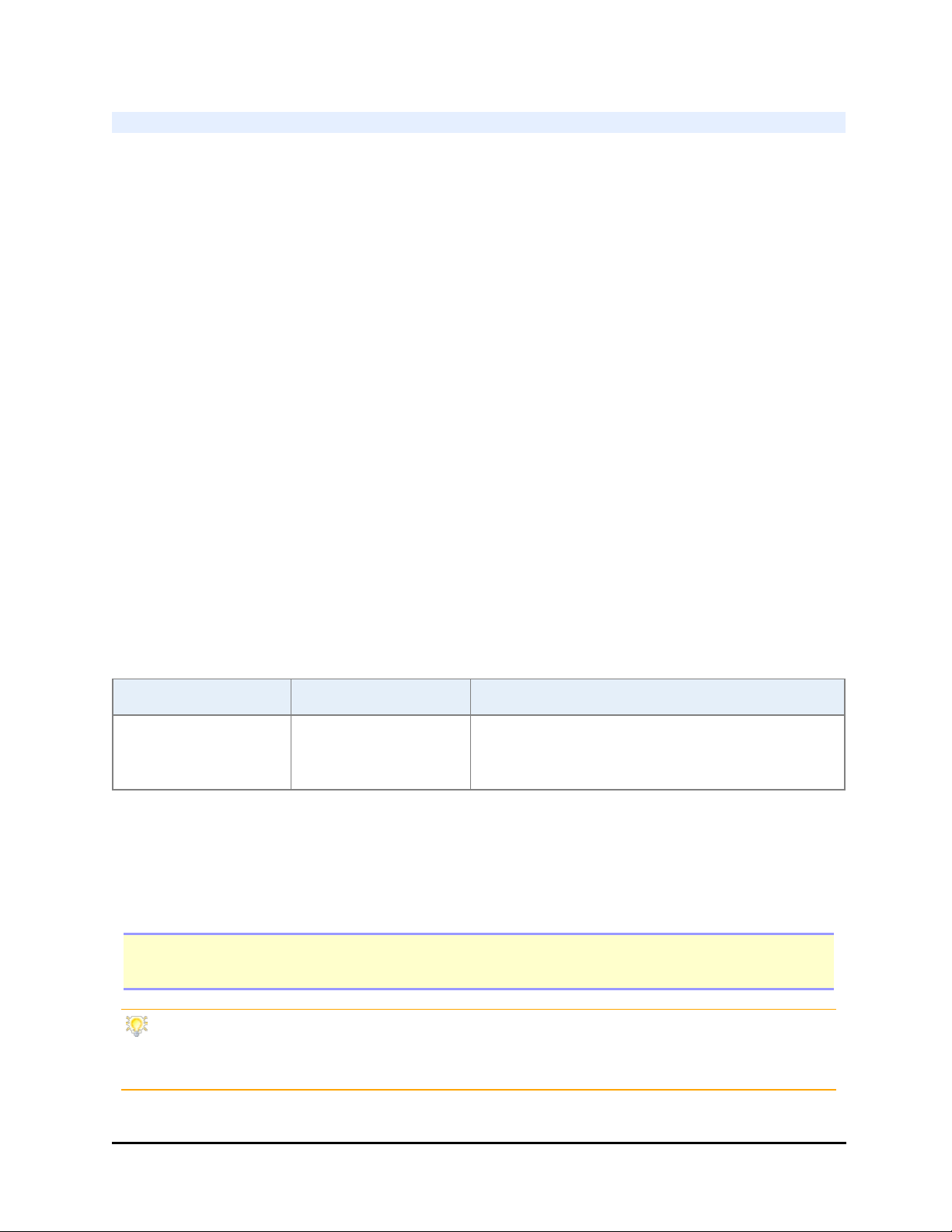
52 | Chapter 3: Operation
Plate Lid Definition Files
To distinguish between a microplate and its lid, the BioStack must know the precise
dimensions of each. BioTek provides plate lid definition files for the most popular
microplate types. You must create your own plate lid definition files for plate types
not provided.
Essential Information:
Gen5 defines the plate lid's dimensions in its Plate Type Database record. The current
plate type record always informs the protocol/experiment of the defined
dimensions. You may need to add lid dimensions to an existing plate type file or
create a new record.
The liquid handlers do not support a plate type database, so the Plate Lid
Definition files are stand-alone, i.e., there is no connection between the plate type
and the plate lid file.
When running the liquid handlers, be aware that a copy of the Plate Lid Definition
file is attached to the protocol when it's selected. The copy no longer refers to, nor
retains a tie to the selected lid definition file. In other words, if the Plate Lid
Definition file is subsequently changed, the changes will not be applied to the copy
of the file attached to your protocol. You must edit the protocol and reselect the
Plate Lid Definition file to apply any changes.
To create your own Plate Lid Definition file:
LHC Gen5/Gen5 TS Touch Screen
Select Tools>Lid
Definition.
Select
System>Plate
Types.
Select Instrument>Next>BioStack and
press Lid Definitions.
1. Open the lid definition or plate type file that most closely matches your labware.
2. Use calipers to measure your plate and lid dimensions.
3. Overwrite the values in the selected file, retaining the advanced default settings.
4. "Save as" the file, giving it a unique name.
Note: Liquid Handlers with Keypads: You must control the instruments using LHC software
to process plates with lids.
Import Plate Lid Definition files: You can share files with other users or obtain them
from BioTek and transfer them to your system. Review instructions provided with your
software or instrument.
BioStack™ Microplate Stacker
Page 75

Microplate Dimensions
l Plate Width: short-side width of the plate.
l Plate Height: height from base to top.
Microplate and Lid Dimensions
Obtain values from the
microplate manufacturer's
data sheet, when available.
Otherwise, use calipers to
precisely measure the
microplate, its lid, and its
stacking properties in µm
(microns).
Processing Plates with Lids | 53
Cross section of two plates with lids stacked (short side, 96-well)
Use the plate height and width values provided by the manufacturer, and any other
relevant measurements included in their data sheets. These dimensions are used to
calculate the gripper height and finger positions, which are critical to proper
operation.
BioTek Instruments, Inc.
Page 76

54 | Chapter 3: Operation
Measurements are recorded in
µm: microns or micrometers. Add
three decimal places to your mm
measurements.
BioStack 4 needs these dimensions to process microplates
with lids:
l Measure the height of the skirt on both long and short
sides of the plate. SLAS calls the skirt "flange."
l
Lid Grip Width: short side width measurement (see
image above).
l
Plate Grip Width: short side width measurement;
the plate is narrower at its top, where the gripper grabs
it, than its bottom, where the skirt widens.
l
Stacked Plate-with-Lid Height: the span from
the bottom of the plate to the bottom of the plate above
it when stacked with lids, excluding the protrusions on
top of the lid.
l
Plate-on-Lid Height: during processing the
BioStack moves an empty lid and the next plate to be
processed together. See below.
Lid Dimensions
l Long side skirt height: Height of the plate skirt (or flange) on the long side of the plate
(from plate base to top of skirt) at its highest point.
l Short side skirt height: Same as above, on the short side.
l Lid grip width: The short-side width of the lid; tells the gripper how far to close when
gripping a lid.
l Plate on lid height: With a plate on top of a lid, the distance from the bottom of the lid
to the top of the plate. One step in the process moves the current plate's lid and the
next plate together to the carrier.
l Plate grip width: width (narrow side) of the plate, measured above the skirt (or
flange); tells the gripper how far to close when gripping a plate (as opposed to the
under plate grip) a plate.
l Stacked plate with lid height: Hold together a stack of plate/lid/plate. Measure base of
one plate to the base of the next plate.
Plate Lid Advanced Dimensions
Typically, the BioStack 4 will smoothly process plates with lids using the default
values for these parameters. However, if you experience processing problems, like
dropped lids, minor adjustments to these values may restore expected performance.
BioStack™ Microplate Stacker
Page 77
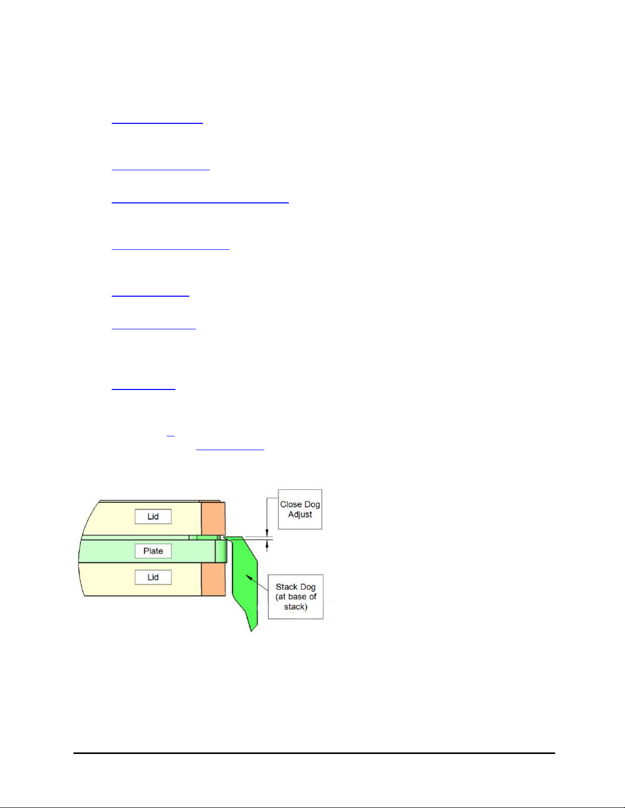
Processing Plates with Lids | 55
Review these descriptions of the parameters, and select the link to view a graphical
image, to help you determine how to modify the values.
l Close dog adjust: When retrieving a plate or plate and lid from the stack, how far
above (positive value), or how far below (negative value) the top of the skirt that the
dogs will close.
l Lid point grip offset: When gripping a lid, how far below the top of the lid the gripper
fingers will contact.
l Plate point grip over long side skirt: When gripping a plate, how far above the long side
skirt the gripper fingers will contact; a negative value means the plate will be gripped
on the skirt.
l Point grip release gap: When gripping a plate or lid on the sides (as opposed to the
under plate grip), how far above the carrier the base of the plate or lid is when
releasing it (i.e., how far it will drop).
l Plate clearance: When moving a plate or lid over another plate or lid on the carrier,
how much vertical clearance is allowed between the plates or lids.
l Loose grip offset: When using an under-plate grip, just before moving into a carrier,
the gripper fingers are separated slightly to allow the plate to adjust horizontally to the
carrier it’s being placed in. Loose grip offset is how much wider the fingers are
compared to the defined plate width.
l Lid overlap: When placing a lid on a plate, how far the lid is overlapped with the top of
the plate before switching from a slow to a fast vertical move. If this value is zero,
then the entire vertical move is fast.
l Stay-on lid: Identifies qualifying labware, i.e., certain low-density microplates that
meet dimension requirements.
Close Dog Adjust
BioTek Instruments, Inc.
Page 78
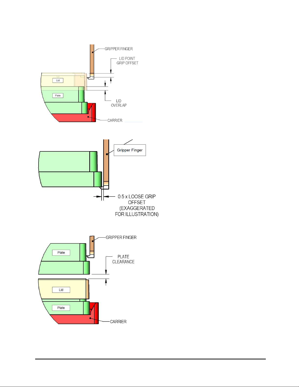
56 | Chapter 3: Operation
Lid Point Grip and Lid Overlap
Loose Grip Offset
Plate Clearance
BioStack™ Microplate Stacker
Page 79
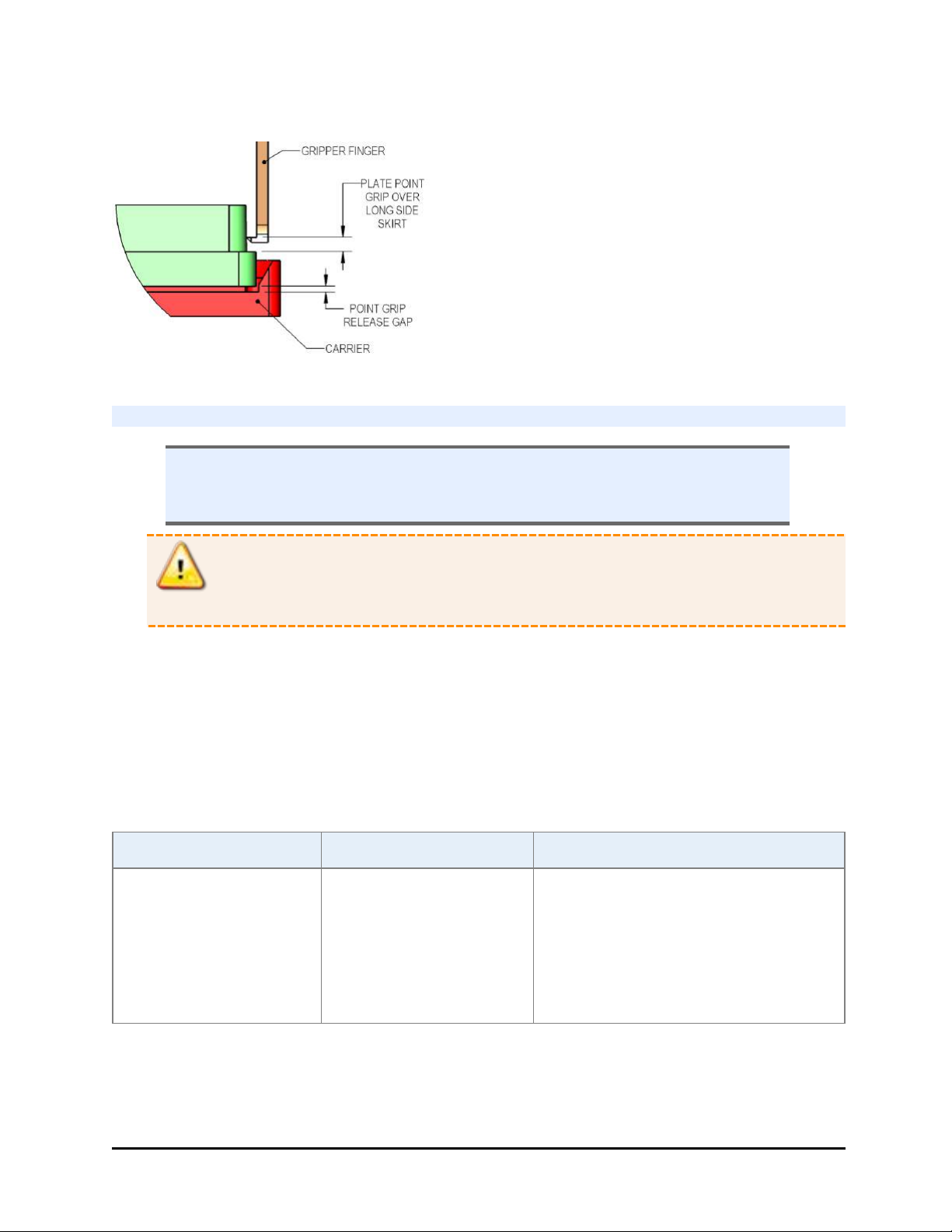
Point Grip
Start Up the BioStack
n Always turn on the BioStack before turning on the interfacing instrument.
BIOSTACK2WR: Make sure the gripper can be homed without causing a
collision.
Processing Plates with Lids | 57
Warning! Keep hands away from the BioStack's gripper and plate carrier during
power-up.
The BioStack runs its system test when started. The LED on the back shows the
status:
l LEDflashing indicates an error condition.
l LED not flashing = system test passed.
If the system test fails, turn on the interfacing instrument. Its system test will run.
Liquid Handlers
LHC Keypad Touch screen
1. Select
Tools>BioStack
Utilities.
2. Click Reset
BioStack.
1. Press
UTIL>Setup
Menu.
2.
Select g,
BIOSTK > ALIGN
> HOME.
1. At the Home screen, press
Instrument.
2. Select Next > BioStack and
press Get Basecode Version.
BioTek Instruments, Inc.
Page 80

58 | Chapter 3: Operation
Readers
Gen5/Gen5 TS
l Select System > Instrument Control to get the reader's software information.
Precision/XS
BioStack PC Control Software
l Click Get On-board values now.
If software information is displayed without error, the BioStack’s Checksum Test
completed successfully.
If an error code displays, look it up in the Troubleshooting chapter.
l If the System Test fails, the LED status light flashes repeatedly. If this happens, turn
off the BioStack. Make sure there is no plate on the carrier, and check for any
obstructions. Ensure that all of the shipping hardware has been removed. If you cannot
resolve the problem, contact BioTek’s Technical Assistance Center for guidance.
BioStack™ Microplate Stacker
Page 81

Chapter 4
Maintenance
Properly maintaining the BioStack is the key to reliable
performance.
Overview 60
Recommended Maintenance Schedule 60
Warnings and Precautions 61
Required Materials 61
Routine Cleaning Procedure 63
Decontamination 64
Tools and Supplies 65
Decontaminate the BioStack 65
Cleaning and Lubricating the Linear Ways 66
Page 82

60 | Chapter 4: Maintenance
Overview
Maintenance comprises a set of procedures to be performed regularly to maintain
equipment in top condition. During normal operation, debris and dust from plate
wear can accumulate on the microplate stacks, carrier surface, and other plate
transport components.
Regular maintenance of the BioStack is the responsibility of the user and is required
for continuous problem-free operation. Adherence to the Recommended
Maintenance Schedule below reduces problems caused by dust and debris,
maximizes running time, and extends the life of the BioStack.
Recommended Maintenance Schedule
Frequency
TASK
Clean plate carrier, stacks, and
exposed surfaces
Decontaminate the instrument
Clean and lubricate linear ways
Daily/As
Needed
ü
Monthly
ü
Every 6
Months
Before Storage or
ü ü
Shipment
ü
ü
BioStack™ Microplate Stacker
Page 83

Warnings and Precautions | 61
Warnings and Precautions
Please read the following before performing any Maintenance procedures:
Warning! Internal Voltage.Turn off and unplug the instrument for all
maintenance and repair operations.
i
Caution: The barcode scanner (if equipped) is housed in a protective cover. Do
i
Warning! Wear protective gloves when handling contaminated instruments.
Gloved hands should be considered contaminated at all times; keep gloved
hands away from eyes, mouth, nose, and ears.
Warning! Mucous membranes are considered prime entry routes for infectious
agents. Wear eye protection and a surgical mask when there is a possibility of
aerosol contamination. Intact skin is generally considered an effective barrier
against infectious organisms; however, small abrasions and cuts may not
always be visible. Wear protective gloves when handling contaminated
instruments.
Important! Do not immerse the instrument, spray it with liquid, or use a
dripping-wet cloth. Do not allow water or other cleaning solution to run into the
interior of the instrument. If this happens, contact BioTek’s Technical
Assistance Center.
not allow cleaning solution to seep into the narrow opening in the cover, where
it may come into contact with the scanner. Do not scratch or damage the mirror
during cleaning
Important: BioTek Instruments, Inc. recommends the use of decontamination
solutions and methods based on our knowledge of the instrument and
recommendations of the Centers for Disease Control and Prevention (CDC).
Neither BioTek nor the CDC assumes any liability for the adequacy of these
solutions and methods. Each laboratory must ensure that decontamination
procedures are adequate for the biohazard(s) they handle
Required Materials
For routine cleaning and decontaminating:
l Dish soap or other mild cleaner
l Deionized or distilled water
l Clean, lint-free disposable towels
BioTek Instruments, Inc.
Page 84

62 | Chapter 4: Maintenance
l 70% isopropyl alcohol or ethanol (for decon)
l For barcode scanner: lens cleaning solution and lens tissue.
For cleaning/lubricating the linear ways:
l Grease kit, BioTek PN 7110017 (provided)
l Clean, lint-free disposable towels
l Lint-free swabs or wipes
l Toothbrush
l Instructions for performing the Verify Test (in the instrument-specific
installation instructions).
n Protective gloves, biohazard trash bags, lab coat, safety glasses, surgical mask
n In the cleaning procedures, when not otherwise specified, “water” means either
deionized or distilled water.
BioStack™ Microplate Stacker
Page 85

Routine Cleaning Procedure | 63
Routine Cleaning Procedure
n Read the Warnings & Precautions on page 61.
Perform these steps daily and before storage or shipment to clean the carrier surface
and microplate stacks, all other exposed surfaces, and, if applicable, the barcode
scanner:
1. Important: Turn off the BioStack and disconnect its power supply.
2. Remove the microplate stacks.
3. Wet a clean cotton cloth with water, or with water and mild detergent, and
thoroughly wring it out so that liquid does not drip from it.
l Wipe the inside and outside of the stacks and the plate-stacking pedestal
(if used).
l Wipe the carrier surface, lifts, gripper, wrist, all other exposed surfaces of
the BioStack and the aligning hardware.
4. Moisten a cotton swab with water, alcohol, or with water and mild detergent.
l Clean the gripper fingers.
l Clean the plate dogs.
5. If the barcode scanner is installed:
l Ensure that cleaning solution does not seep into the narrow opening in the
cover that protects the scanner.
l Lens cleaning solution and lens tissue may also be used to clean the
mirror.
l Be very careful not to scratch or damage the mirror!
l Gently wipe the external surface of the scanner assembly, including the
scanner’s protective cover, mounting bracket, cable, and mirror.
6. If detergent was used, wipe all surfaces with a cloth moistened with water.
7. Use a clean, dry cloth to dry all wet surfaces.
8. Reassemble the instrument.
BioTek Instruments, Inc.
Page 86

64 | Chapter 4: Maintenance
Decontamination
Any laboratory instrument that has been used for research or clinical analysis is
considered a biohazard and requires decontamination prior to handling.
Decontamination minimizes the risk to all who come into contact with the
instrument during shipping, handling, and servicing. Decontamination is required
by the U.S. Department of Transportation regulations. Persons performing the
decontamination process must be familiar with the basic setup and operation of the
instrument.
The recommended frequency for decontamination is at least monthly, and before
storage or shipment.
n Important! BioTek Instruments, Inc. recommends the use of the following
decontamination solutions and methods based on our knowledge of the
instrument and recommendations of the Centers for Disease Control and
Prevention (CDC). Neither BioTek nor the CDC assumes any liability for the
adequacy of these solutions and methods. Each laboratory must ensure that
decontamination procedures are adequate for the biohazards they handle.
Warning! Internal Voltage. Turn off and unplug the instrument for all
decontamination operations.
n Do not immerse the instrument, spray it with liquid, or use a dripping-wet
cloth. Do not allow the cleaning solution to run into the interior of the
instrument. If this happens, contact the BioTek TAC.
n Wear prophylactic gloves when handling contaminated instruments. Gloved
hands should be considered contaminated at all times; keep gloved hands away
from eyes, mouth, nose, and ears. Eating and drinking while decontaminating
instruments is not advised.
n Mucous membranes are considered prime entry routes for infectious agents.
Wear eye protection and a surgical mask when there is a possibility of aerosol
contamination. Intact skin is generally considered an effective barrier against
infectious organisms; however, small abrasions and cuts may not always be
visible. Wear protective gloves when performing the decontamination
procedure.
BioStack™ Microplate Stacker
Page 87

Decontamination | 65
Tools and Supplies
70% isopropyl alcohol (as a bleach alternative)
Deionized or distilled water
Safety glasses
Surgical mask
Protective gloves
Lab coat
Biohazard trash bags
Clean cotton cloths
Decontaminate the BioStack
Perform these steps to decontaminate the carrier surface and microplate stacks, all
other exposed surfaces, and, if applicable, the barcode scanner:
1. Important: Turn off the BioStack and disconnect its power supply.
2. Remove the microplate stacks.
3. Wet a clean cotton cloth with 70% alcohol, then thoroughly wring it out so that
liquid does not drip from it.
4. Wipe the inside and outside of the stacks and the plate-stacking pedestal (if
used).
5. Wipe the carrier surface, lifts, gripper, wrist, all other exposed surfaces of the
BioStack, and the aligning hardware.
6. If the barcode scanner is installed:
l Ensure that cleaning solution does not seep into the narrow opening in the
cover that protects the scanner.
l Lens cleaning solution and lens tissue may also be used to clean the
mirror.
l Be very careful not to scratch or damage the mirror!
l Gently wipe the external surface of the scanner assembly, including the
scanner’s protective cover, mounting bracket, cable, and mirror.
7. Wait 20 minutes. Moisten a cloth with deionized or distilled water and wipe all
surfaces that have been cleaned with the alcohol.
8. Use a clean, dry cloth to dry all wet surfaces.
BioTek Instruments, Inc.
Page 88

66 | Chapter 4: Maintenance
9. Discard the used gloves and cloths using a biohazard trash bag and an
approved biohazard container.
10. Follow the instructions in Cleaning and Lubricating the Linear Ways below to
lubricate the linear ways to prevent rust from forming.
11. Reassemble the instrument.
Cleaning and Lubricating the Linear Ways
n Read the Warnings & Precautions on page 61.
Note: Do not let the gripper flop around! Before moving the BioStack 3 or BioStack 4,
secure the gripper with a rubber band or tape to prevent it from losing its alignment. A
complex recalibration is required if it is knocked out of position.
Periodic cleaning and lubrication of the linear ways and screws on the two stack
lifters and the plate carrier is necessary to ensure optimum performance of these
components during plate transfer.
A grease kit (BioTek PN 7110017) is included in your BioStack package contents.
Use a clean towel, rubber gloves, a toothbrush, and lint-free swabs or wipes
(moistened with alcohol to assist the process), and the lubricant contained in the kit
when performing this procedure.
Perform these steps every six months and before storage or shipment:
BioStack™ Microplate Stacker
Page 89

Cleaning and Lubricating the Linear Ways | 67
1. Important! Turn off the BioStack and disconnect the power supply.
2. Gently turn the instrument onto its side so that the bottom of the BioStack is
facing you. (If the barcode scanner is installed, turn the BioStack on the side
without the scanner.)
3. Using lint-free swabs or wipes, remove old, possibly contaminated grease from
the three linear ways.
4. Allow these parts to dry completely.
BioTek Instruments, Inc.
Page 90
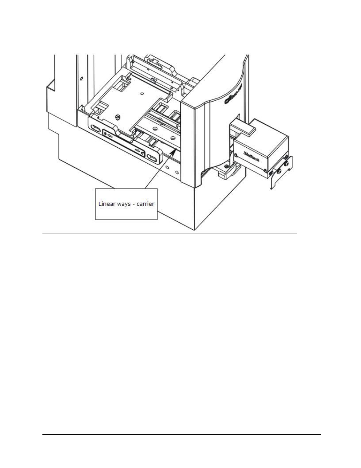
68 | Chapter 4: Maintenance
5. Apply a small amount of new lubricant to all surfaces of the linear ways,
spreading thin layers and working the grease into the surfaces with a
toothbrush.
l Ensure that you lubricate the sides of the linear ways, since ball bearings
travel on these surfaces.
6. Return the BioStack to its upright position and reconnect its power supply.
7. Turn on the BioStack and run a Verify Test to confirm that moving the BioStack
did not compromise its alignment with the interfacing instrument. (Refer to the
instrument-specific PDF file.)
l If the Verify Test passes, the BioStack is ready to resume normal operation.
l If the Verify Test fails, realign the gripper with the plate carrier using the
Alignment Utility and rerun the Verify Test. If the test continues to fail,
contact BioTek’s Technical Assistance Center.
BioStack™ Microplate Stacker
Page 91

Chapter 5
Qualification
This chapter provides instructions for periodically testing the
instrument to verify that it meets performance specifications.
Overview 70
Recommended Qualification Schedule 70
Installation Qualification 72
Operational Qualification Procedure 72
Page 92

70 | Chapter 5: Qualification
Overview
Qualification of the BioStack involves two activities:
l Qualification of installation and setup (IQ)
l Qualification of routine capability (OQ)
Qualification tasks and tests for the BioStack include installing the BioStack with the
interfacing instrument, and running these tests:
l The System Test verifies the BioStack’s system components, such as the
input and output stack lifters, carrier, gripper, and wrist.
l The Checksum Test verifies the basecode software of the BioStack or
interfacing instrument against internal checksum values to ensure that no
corruption has occurred.
l The Instrument Alignment Utility aligns the BioStack’s gripper with the
interfacing instrument’s carrier or supply station (Precision/XS).
l The Verify Test confirms whether the BioStack’s gripper has been properly
aligned with the interfacing instrument’s carrier or supply station.
l The Scanner Test confirms installation of the optional barcode scanner.
n An instrument qualification package (PN 7310530) for the BioStack is available
for purchase. The package contains detailed procedures for performing
Installation/Operational Qualification (IQ/OQ) and Preventive Maintenance
(PM), and extensive checklists and logbooks for recording data and results.
Contact BioTek for more information.
Recommended Qualification Schedule
TASKS/TESTS IQ OQ
Set Up the BioStack:
Unpack/Inspect the BioStack
Initially Every 3
months
P
Check required and optional components
Review safety information
Select an appropriate location
BioStack™ Microplate Stacker
P
P
P
Page 93

Recommended Qualification Schedule | 71
TASKS/TESTS IQ OQ
Remove the shipping hardware
Install the power supply
If applicable: Change Wrist Angle
If applicable: Change setting for 50-plate stacks
Install the BioStack with the interfacing instrument*
If applicable: Connect the host computer to the instruments, install
software, and test communication*
Run the System Test
Run the Checksum Test
Run the Instrument Alignment Utility**
Run the Verify Test**
If applicable: Install the BioStack barcode scanner and run the
Scanner Test‡
P
P
P
P
P
P
P P
P P
P
P If Verify
Test fails
P P
P
* Refer to the instrument-specific instructions.
** Perform the Instrument Alignment and Verify Test whenever the BioStack is
moved from one location to another.
n Performance Qualification (PQ) procedures are not required for the BioStack.
Performing chemistry testing on the microplates is not applicable to the
BioStack.
‡ Install the Barcode Scanner on page 94.
BioTek Instruments, Inc.
Page 94

72 | Chapter 5: Qualification
Installation Qualification
Installation Qualification confirms that the BioStack and its components have been
supplied as ordered, and ensures that they are assembled and configured properly
for your lab environment.
n See Recommended Qualification Schedule on page 70 for the recommended IQ
tasks and tests.
n Record software information in a copy of the Software Data Sheet provided in the
instrument-specific PDF file.
n The IQ procedure should be performed initially (before the BioStack is used for the first
time). Some of the IQ steps should be performed again if the instruments are moved
from one location to another within the laboratory.
n The successful completion of the IQ verifies that the instruments and their components
are installed correctly.
Operational Qualification Procedure
Operational Qualification confirms that the BioStack’s onboard software is operating
properly and verifies the gripper-to-instrument carrier alignment and to confirm that
the optional barcode scanner is operating properly.
n See Recommended Qualification Schedule on page 70 for the recommended OQ
tasks and tests.
n We recommend performing the OQ procedure every three months and after any major
repair or hardware or software upgrade.
n The successful completion of the OQ confirms that the BioStack is operating correctly.
The actual frequency, however, may be adjusted depending on your
organization’s general guidelines for device validation/verification. Minimally,
the OQ procedure should be conducted quarterly and after any major repair or
upgrade to the hardware or software.
BioStack™ Microplate Stacker
Page 95

Chapter 6
Troubleshooting & Error
Codes
This chapter provides guidelines for error recovery and
troubleshooting performance problems.
Troubleshooting 74
Communication Error Codes 74
Page 96

74 | Chapter 6: Troubleshooting & Error Codes
Troubleshooting
If the microplates are dropping improperly, hanging up, or not being picked up and
transferred as expected, here are some methods for correcting problems with nonstandard plate types that are not transferring properly:
l Plate Stacked Height: when controlling the BioStack 3 or BioStack 4 (and not
processing lids) with Gen5, LHC or touch screen, define a custom plate stacked height
to improve the gripper's position on the plate.
l Change Setting for Low-Profile Plates on page 89: change the Plate Height
setting.
l Loosen Plate Carrier Set Screws - BioStack 4 Only on page 90
l Adjust the Stack Dogs on page 91: physically change the gap between the plate
dogs.
Communication Error Codes
General Communication Errors
Depending on your configuration, you may see these errors in the Liquid Handling
Control software, Gen5 software, BioStack PC Control Software, or Precision Power
software.
Communication errors include errors found when sending messages to an
instrument, and receiving messages back from an instrument, as well as timer-based
errors when waiting for a response.
Communication Errors
Code Probable Causes
-1 General failure in talking to instrument driver software.
This error indicates that something is not correct with the driver software, or
with the communications.
Try closing the application and restarting. If this has no effect, try rebooting the
PC.
-3 Operation canceled by user.
There is a problem with the driver software or with the communications.
Try closing the application and restarting. If this has no effect, try rebooting the
PC.
-4 Unable to start delay timer associated with waiting for message response from
instrument.
This error indicates that there may be too many applications using timers on
the PC (there are only eight timers available), or the delay timer is already set.
BioStack™ Microplate Stacker
Page 97

Communication Errors
Close the application and try again.
Close one or more other applications that may be using timers.
-5 Invalid request.
The BioStack is not in the correct mode for handling this request.
Restart the BioStack.
-6 Unable to process request.
The BioStack is not in the correct mode for handling this request.
Restart the BioStack.
-401 Object doesn’t exist.
This error indicates that the driver software has somehow lost information on
the instrument it is trying to communicate with.
Restart the application.
-504 Unable to open a serial port.
This error indicates that either another application is using the serial port, or
the port was opened either by another application or by the BioStack PC Control
Software, but was not closed properly.
Close the other application.
If that doesn’t work, close the BioStack PC Control software and restart it.
Lastly, reboot the PC.
Communication Error Codes | 75
-505 Unable to write all of the serial data.
Try restarting the application.
-506 Timeout while reading in serial data, or incorrect number of serial characters
were read in.
Check the serial cable connection to ensure it is not loose.
Check to see if any other application is very CPU intensive.
Try restarting the application.
-507 Checksum error with the serial data read in.
Attempt the operation again.
Try restarting the application.
-508 When attempting to talk to the instrument, the instrument basecode software
returned a NAK, indicating it did not recognize the request.
Attempt the operation again.
Try restarting the instrument.
Try restarting the application.
-509 PC software received back more data than it was expecting.
Unlikely to be seen. It is expected that a –506 would be sent instead.
Try restarting the application.
BioTek Instruments, Inc.
Page 98

76 | Chapter 6: Troubleshooting & Error Codes
Communication Errors
-510 Invalid message object.
This error indicates that either the instrument basecode software or the PC
software doesn’t recognize the message sent. This is unlikely to be seen, but
could possibly happen if the software fell out-of-sync with the characters sent
back and forth.
Try restarting the application and the instrument.
-511 Invalid message body size.
This error indicates that either the instrument basecode software or the PC
software received an invalid count of expected characters for a specific
message. This is unlikely to be seen, but could possibly happen if the software
fell out of sync with the characters sent back and forth.
Try restarting the application and the instrument.
-512 Serial message timeout waiting for response from the instrument.
Check the instrument to ensure it has powered-up correctly and is in a good
operational state (i.e., the light is on, but NOT flashing).
Check the cable connections and the cable itself.
Try restarting the application.
BioStack Instrument Errors
Depending on your instrument and software configuration, you may see these
errors on the instrument’s display or in the controlling PC software.
n On instruments with keypads: If a four-digit code is prefixed with B- or
“BIOSTACK ERROR” appears, the code was generated by the BioStack.
Otherwise, the code was most likely generated by the interfacing instrument;
refer to that instrument’s operator’s manual.
n Precision Power: These errors are usually displayed as text messages, and
occasionally as an error code without the text (e.g., 1000 or 0x1000). Refer
also to the Precision/XS Operator’s Manual for a list of BioStack instrument
errors.
Code Probable Causes
020# Could not find opto sensor. # = sensor; see page 86 for a list of sensor
numbers. This error indicates that a sensor was not tripped. Plates sticking
because wells are overfilled, causing a jam. Plate not seated properly,
causing a jam. Plate stack not installed properly. Shipping block still
installed. Plate dimensions are incompatible with BioStack.
020D Destination lift motor could not find opto sensor. Occurs during
BioStack™ Microplate Stacker
Page 99

Communication Error Codes | 77
Code Probable Causes
autocalibration. Carrier jig installed backward. Oil film on gold-plated jig not
allowing contact to be made. Jig connector not making contact or pulled out of
connector. Destination stack not installed correctly. Lead screw unglued from
motor. Destination lift motor or driver circuit defective. Linear way jam
causing motor to lose steps.
0300 One or both Stack Locks are open. Always lock the stacks before operation.
040# Failed positional verify. # = motor; see page 87 for a list of motor numbers.
This error indicates that an axis failed its positional verify test. After moving
a predefined number of steps from a home position, the motor should return
to the home position in the proper amount of time and steps. If the axis
moves back to its home position in the wrong amount of time, or uses too few
or too many steps, the test fails. A belt may be slipping due to incorrect
tension, a loose motor pulley, or a loose belt clamp. This can also be caused
by a defective motor drive circuit. Gripper motor error (0407): If the
BioStack2WR is not on, its gripper falls to the fully down position. When the
interfacing instrument is powered on and goes through its normal homing
sequence, the BioStack gripper gets in the way and causes the attached
instrument to error. The solution is to power up the BioStack first and keep
the BioStack powered on. If the BioStack is powered off, raise the
claw/gripper assembly manually above the interfacing instrument's carrier
before powering on. Once its initialization is complete, then power on the
interfacing instrument.
040D Destination lift motor could not find opto sensor. Occurs during
autocalibration. Carrier jig installed backwards. Oil film on gold-plated jig not
allowing contact to be made. Jig connector not making contact or pulled out of
connector. Destination stack not installed correctly. Lead screw unglued from
motor. Destination lift motor or driver circuit defective. Linear way jam
causing motor to lose steps.
055# Motor in use error. # = motor; see page 87 for a list of motor numbers. An
internal programming error. A command was issued to move a motor that
was already in motion. Turn the instrument off/on. If the error persists,
contact BioTek TAC.
0600 Calibration data missing. Nonvolatile calibration data may be missing or
corrupt. One or more components of the instrument may need to be
recalibrated. Turn the instrument off/on, and if the error persists, contact
BioTek TAC.
0650 Autocal jig placement error. The autocal jig was installed incorrectly. Position
the jig correctly and retry.
0700 Failed interface configuration checksum test. Nonvolatile configuration data
associated with the external instrument interface may be missing or corrupt.
Turn the instrument off/on. If the error persists, contact BioTek TAC.
BioTek Instruments, Inc.
Page 100

78 | Chapter 6: Troubleshooting & Error Codes
Code Probable Causes
0750 Failed Instrument Dimension structure checksum test. Nonvolatile
configuration data associated with the external instrument carrier dimensions
may be missing or corrupt. Turn the instrument off/on. If the error persists,
contact BioTek TAC.
080# Motor was not homed successfully. # = motor; see page 87 for a list of
motor numbers. This error is usually only seen during the autocalibration
sequence. See the probable causes for 020# on the preceding page.
0900 Memory allocation error. Contact BioTek TAC.
1000 Autocalibration data checksum failed at power-up. Nonvolatile calibration
data may be missing or corrupted. One or more components on the
instrument may need to be recalibrated. Turn the instrument off/on. If the
error persists, contact BioTek TAC.
1200 Internal RAM test error. A failure of the internal random access memory was
detected during the powerup test. Turn the instrument off/on, and if the error
persists, contact BioTek TAC.
1300 Timeout sending or receiving serial data. Cable not connected, or loose.
Incorrect cable. Interfacing instrument not set up properly. BioStack may be
in an error state. Check for obstructions and turn off/on. Gen5 or controlling
software not set up properly.
1303 Serial receive buffer overflow. A communication error—see error 1300.
1304 Serial message checksum. A communication error—see error 1300.
1307 Received request object not supported. A communication error—see error
1300.
1308 Message body size exceeds max limit. A communication error—see error
1300.
1309 Max requests currently running. A communication error—see error 1300.
1501 Internal 5V power supply test error. Check connections to the external power
supply. Turn the instrument off/on, and if the error persists, contact BioTek
TAC.
1502 External power supply test error. Check connections to the external power
supply. Check AC line voltage. Turn the instrument off/on, and if the error
persists, contact BioTek TAC.
1600 Failed attempted plate transfer from output stack to input stack. This error
indicates that no plate was found on the BioStack carrier after attempted
plate retrieval from the output stack. Plate stack not installed properly. Plate
dimensions are incompatible with BioStack.
BioStack™ Microplate Stacker
 Loading...