

Page 1

800™ TS
Absorbance Reader
Instructions for Use
BioTek® Instruments, Inc.
© 2017
PN 1561011, Rev A
Page 2

BioTek Instruments, Inc.
ii | Notices
Notices
BioTek® Instruments, Inc.
Highland Park, P.O. Box 998
Winooski, Vermont 05404-0998 USA
All Rights Reserved
© 2017, BioTek® Instruments, Incorporated. No part of this publication may be reproduced, transcribed, or
transmitted in any form, or by any means electronic or mechanical, including photocopying and recording, for any
purpose other than the purchaser’s use without written permission of BioTek Instruments, Inc.
Trademarks
BioTek® is a registered trademark, and 800™ TS and Gen5™ are trademarks of BioTek Instruments, Inc. BioCell™ is
a trademark of BioTek Instruments and is patented under U.S. patent number 5,963,318.
Microsoft®, Windows®, and Excel® are either registered trademarks or trademarks of Microsoft Corporation in
the United States and/or other countries.
All other trademarks are the property of their respective holders.
Restrictions and Liabilities
Information in this document is subject to change and does not represent a commitment by BioTek Instruments,
Inc. Changes made to the information in this document will be incorporated in new editions of the publication. No
responsibility is assumed by BioTek for the use or reliability of software or equipment that is not supplied by
BioTek or its affiliated dealers.
Page 3

Contact Information | iii
Contact Information
BioTek® Instruments, Inc.
Highland Park, P.O. Box 998
Winooski, Vermont 05404-0998 USA
Global Service and Support
BioTek instrument service and repair is available worldwide at one of BioTek's
International Service Centers and in the field at your location. To arrange for service or
repair of your instrument, contact the office nearest you; visit www.biotek.com for up-todate contact information. For customer service, sales, and technical assistance, refer to the
information below.
Customer Service and Sales
Internet: www.biotek.com
Phone: 888-451-5171 (toll-free in the U.S.)
802-655-4740 (outside the U.S.)
Fax: 802-655-7941
Email: customercare@biotek.com
Service/Technical Assistance Center (TAC)
Phone: 800-242-4685 (toll-free in the U.S.)
802-655-4740 (outside the U.S.)
Fax: 802-654-0638
Email: tac@biotek.com
European Coordination Center/Authorized European Representative
BioTek® Instruments GmbH
Kocherwaldstrasse 34
D-74177 Bad Friedrichshall
Germany
Internet: www.biotek.de
800 TS
Phone: +49 (0) 7136 9680
Fax: +49 (0) 7136 968 111
Email: info@biotek.de
Page 4

BioTek Instruments, Inc.
iv | Instructions for Use Requirements
Instructions for Use Requirements
This document fulfills the basic needs of persons operating this device, according to the
requirements of the In Vitro Diagnostic Directive for “Instructions for Use.” Some of the
device's higher-level functions and features, as well as certain detailed maintenance and
qualification routines, are described in the Synergy Neo Operator's Manual.
Intended Use Statement
The 800 TS is a single-channel, filter-based absorbance reader designed to perform
measurements of samples in a microplate format. The performance characteristics of the
data reduction software have not been established with any laboratory diagnostic assay.
Users must evaluate this instrument and PC-based software in conjunction with their
specific assay(s). This evaluation must include the confirmation that performance
charactertistics for the specific assay(s) are met.
Quality Control
It is considered good laboratory practice to run laboratory samples according to
instructions and specific recommendations included in the assay package insert for the test
to be conducted. Failure to conduct Quality Control checks could result in erroneous test
data.
Warnings
Operate the instrument on a level, stable surface away from excessive humidity.
Bright sunlight or strong incandescent light can reduce the linear performance
range of the instrument.
Measurement values may be affected by extraneous particles (such as dust) in the
microplate wells. A clean work area is necessary to ensure accurate readings.
When operated in a safe environment according to the instructions in this
document, there are no known hazards associated with the instrument. However,
the operator should be aware of certain situations that could result in serious
injury; these may vary depending on the instrument model. See Hazards and
Precautions.
Page 5

Hazards
The following hazards are provided to help avoid injury:
Warning! Power Rating. The instrument’s power supply or power cord must
be connected to a power receptacle that provides voltage and current within
the specified rating for the system. Use of an incompatible power receptacle
may produce electrical shock and fire hazards.
Warning! Electrical Grounding. Never use a plug adapter to connect primary
power to the external power supply. Use of an adapter disconnects the utility
ground, creating a severe shock hazard. Always connect the power cord
directly to an appropriate receptacle with a functional ground.
Warning! Service. Only qualified technical personnel should perform service
procedures on internal components.
Warning! Accessories. Only accessories that meet the manufacturer's
specifications shall be used with the instrument.
Warning! Lubricants. Do not apply lubricants to the microplate carrier or
carrier track. Lubricant on the carrier mechanism or components in the
carrier compartment will attract dust and other particles, which may obstruct
the carrier path and cause the instrument to produce an error.
Hazards | v
Warning! Liquids. Avoid spilling liquids on the instrument; fluid seepage into
internal components creates a potential for shock hazard. If a spill occurs
while a program is running, abort the program and turn off the instrument.
Wipe up all spills immediately. Do not operate the instrument if internal
components have been exposed to fluid. Contact BioTek TAC for assistance.
Warning! Unspecified Use. Failure to operate the equipment according to the
guidelines and safeguards specified in this manual could result in a hazardous
condition.
Warning! Software Quality Control. The operator must follow the
manufacturer’s assay package insert when modifying software parameters
and establishing reading methods. Failure to conduct quality control checks
could result in erroneous test data.
Warning! Reader Data Reduction Protocol. No limits are applied to the raw
measurement data. All information exported via computer control must be
thoroughly analyzed by the operator.
800 TS
Page 6
BioTek Instruments, Inc.
vi | Precautions
Warning! Hot Surface.The tungsten lamp assembly is hot when the
instrument is turned on. Turn off the reader and allow the lamp to cool for at
least 15 minutes before attempting to replace it.
Warning! Internal Voltage. Always turn off the power switch and unplug the
power supply before cleaning the outer surface of the instrument.
Warning! Potential Biohazards. Some assays or specimens may pose a
biohazard. This hazard is noted by the symbol shown here. Adequate safety
precautions should be taken as outlined in the assay’s package insert. Always
wear safety glasses and appropriate protective equipment, such as chemicalresistant rubber gloves and apron.
Precautions
The following precautions are provided to help avoid damage to the instrument:
Caution: Service. The instrument should be serviced by BioTek-authorized
service personnel. Only qualified technical personnel should perform service
procedures on internal components.
Caution: Spare Parts. Only approved spare parts should be used for
maintenance. The use of unapproved spare parts and accessories may result in
a loss of warranty and potentially impair instrument performance or cause
damage to the instrument.
Caution Touchscreen. Do not use sharp implements to operate the
touchscreen. Using a sharp stylus or other implement may damage the display.
Caution: Environmental Conditions. Do not expose the system to temperature
extremes. For proper operation, ambient temperatures should remain within
the range listed in Appendix A, Specifications. Performance may be adversely
affected if temperatures fluctuate above or below this range. Storage
temperature limits are broader.
Caution: Sodium Hypochlorite. Do not expose any part of the instrument to the
recommended diluted sodium hypochlorite solution (bleach) for more than 20
minutes. Prolonged contact may damage the instrument surfaces. Be certain to
rinse and thoroughly wipe all surfaces.
Caution: Power Supply. Use only the power supply shipped with the instrument.
Operate this power supply within the range of line voltages listed on it.
Page 7

Precautions | vii
Caution: Shipping Hardware.The shipping hardware must be removed before
operating the instrument and reinstalled before repackaging the instrument for
shipment.
Caution: Disposal. Dispose of the instrument according to Directive
2012/19/EU, “on waste electrical and electronic equipment (WEEE)” or local
ordinances.
Caution: Warranty. Failure to follow maintenance protocols may void the
warranty. See Chapter 4, Maintenance.
Caution: Electromagnetic Environment. Per IEC 61326-2-6 it is the user’s
responsibility to ensure that a compatible electromagnetic environment for this
instrument is provided and maintained in order that the device will perform as
intended.
Caution: Electromagnetic Compatibility. Do not use this device in close
proximity to sources of strong electromagnetic radiation (e.g., unshielded
intentional RF sources), because these may interfere with the proper operation.
800 TS
Page 8

BioTek Instruments, Inc.
viii | CE Mark
CE Mark
Based on the testing described below and information
contained herein, this instrument bears the CE mark
Refer to the Declaration of Conformity for more specific information.
Directive 2014/30/EU: Electromagnetic Compatibility
Emissions—Class A
The system has been type-tested by an independent, accredited testing laboratory and
found to meet the requirements of EN 61326-1: Class A for Radiated Emissions and Line
Conducted Emissions.
Verification of compliance was conducted to the limits and methods of EN 55011 – (CISPR
11) Class A. In a domestic environment it may cause radio interference, in which case you
may need to mitigate the interference.
Immunity
The system has been type-tested by an independent, accredited testing laboratory and
found to meet the requirements of EN 61326-1 and EN 61326-2-6 for Immunity.
Verification of compliance was conducted to the limits and methods of the following:
EN 61000-4-2, Electrostatic Discharge
EN 61000-4-3, Radiated EM Fields
EN 61000-4-4, Electrical Fast Transient/Burst
EN 61000-4-5, Surge Immunity
EN 61000-4-6, Conducted Disturbances from RFI
EN 61000-4-11, Voltage Dips, Short Interruptions and Variations
Directive 2014/35/EU Low Voltage (Safety)
The system has been type-tested by an independent testing laboratory and was found to
meet the requirements of this Directive. Verification of compliance was conducted to the
limits and methods of the following:
EN 61010-1. "Safety requirement for electrical equipment for measurement, control and
laboratory use. Part 1, General requirements."
EN 61010-2-081. “Particular requirements for automatic and semi-automatic laboratory
equipment for analysis and other purposes.”
EN 61010-2-010. “Particular requirements for laboratory equipment for the heating of
materials.“
Page 9

Electromagnetic Interference and Susceptibility | ix
Directive 2012/19/EU: Waste Electrical and Electronic Equipment
Disposal Notice: Dispose of the instrument according to Directive 2012/19/EU, “on waste
electrical and electronic equipment (WEEE)” or local ordinances.
Directive 98/79/EC: In Vitro Diagnostics (if labeled for this use)
•
Product registration with competent authorities
•
EN 61010-2-101. “Particular requirements for in vitro diagnostic (IVD) medical
equipment.”
•
Traceability to the U.S. National Institute of Standards and Technology (NIST).
Electromagnetic Interference and Susceptibility
USA FCC CLASS A
RADIO AND TELEVISION INTERFERENCE
NOTE: This equipment has been tested and found to comply with the limits for a Class
A digital device, pursuant to Part 15 of the FCC Rules. These limits are designed to provide
reasonable protection against harmful interference when the equipment is operated in a
commercial environment. This equipment generates, uses, and can radiate radio frequency
energy and, if not installed and used in accordance with the instruction manual, may cause
harmful interference to radio communications. Operation of this equipment in a
residential area is likely to cause harmful interference, in which case the user will be
required to correct the interference at their own expense.
In order to maintain compliance with FCC regulations, shielded cables must be used with
this equipment. Operation with non-approved equipment or unshielded cables is likely to
result in interference to radio and television reception.
Canadian Department of Communications Class A
This digital apparatus does not exceed Class A limits for radio emissions from digital
apparatus set out in the Radio Interference Regulations of the Canadians Department of
Communications.
Le present appareil numerique n'emet pas du bruits radioelectriques depassant les limites
applicables aux appareils numerique de la Class A prescrites dans le Reglement sur le
brouillage radioelectrique edicte par le ministere des Communications du Canada.
800 TS
Page 10

BioTek Instruments, Inc.
x | User Safety
User Safety
This device has been type-tested by an independent laboratory and found to meet the
requirements of the following:
•
Underwriters Laboratories UL 61010-1, “Safety requirements for electrical
equipment
requirements.”
•
Canadian Standards Association CAN/CSA C22.2 No. 61010-1, “Safety
requirements
laboratory use; Part 1:
•
EN 61010 Standards, see
for measurement, control and laboratory use; Part 1: General
for electrical equipment for measurement, control and
General requirements.”
CE Mark
starting on page viii.
Page 11
Safety Symbols
Some of the following symbols may appear on the instrument or accessories:
Alternating current
Courant alternatif
Wechselstrom
Corriente alterna
Corrente alternata
Direct current
Courant continu
Gleichstrom
Corriente continua
Corrente continua
Both direct and alternating
current
Courant continu et courant
alternatif
Gleich - und Wechselstrom
Corriente continua y
corriente alterna
Corrente continua e
corrente alternata
Earth ground terminal
Borne de terre
Erde (Betriebserde)
Borne de tierra
Terra (di funzionamento)
Protective conductor
terminal
Borne de terre de
protection
Schultzleiteranschluss
Borne de tierra de
protección
Terra di protezione
Warning, risk of crushing or pinching
Attention, risque d'écrasement et pincement
Warnen, Gefahr des Zerquetschens und
Klemmen
Precaución, riesgo del machacamiento y
sejeción
Attenzione, rischio di schiacciare ed
intrappolarsi
Warning, hot surface
Attention, surface chaude
Vorsicht, heiße Oberfläche
Precaución, superficie caliente
Attenzione, superfice calda
Laser radiation: Do not stare into beam
Rayonnement laser: Ne pas regarder dans le
faisceau
Laserstrahlung: nicht in den strahl blicken
Radiación de laser: No mire fijamente al rayo
Radiazione di laser: Non stare nel fascio
Warning, potential biohazards
Attention, risques biologiques potentiels
Warnung! Moegliche biologische Giftsoffe
Atención, riesgos biológicos
Attenziones, rischio biologico
Caution (refer to accompanying documents)
Attention (voir documents
d'accompanement)
Achtung siehe Begleitpapiere
Atención (vease los documentos incluidos)
Attenzione, consultare la doc annessa
Safety Symbols | xi
800 TS
Page 12

xvi | Safety Symbols
BioTek Instruments, Inc.
Page 13

Installation
Page 14
2 | Package Contents
Package Contents
Item Part #
800 TS Operator's Manual on USB flash drive 1561000
Power supply
Power cord varies according to country of use
USB cable 75108
Blank 4 GB USB flash drive 01087
Dust cover 7332040
Gen5 RC software GEN5RC
Non-incubation models: 01281
Incubation models: 02395
1. Unpack and Inspect the Reader
Save all packaging materials. If you need to ship the reader to BioTek for repair or
replacement, you must use the BioTek-supplied materials. Using other forms of
commercially available packaging, or failing to follow the repackaging instructions,
may void your warranty.
During the unpacking process, inspect the packaging, reader, and accessories for
shipping damage. If the reader is damaged, notify the carrier and your BioTek
representative. Keep the shipping boxes and the packaging materials for the carrier's
inspection. BioTek will arrange for repair or replacement immediately.
1. Place the packaging materials back into the shipping box for reuse if the instrument
needs to be shipped again.
BioTek Instruments, Inc.
Page 15

Remove the Shipping Hardware | 3
2. Remove the Shipping Hardware
Remove and store all shipping hardware before you turn on the reader.
1. Carefully turn the reader upside down on a level surface.
2. Remove the six black screws holding the cover to the base, then lift the base off the
cover and set it right side up on a level surface.
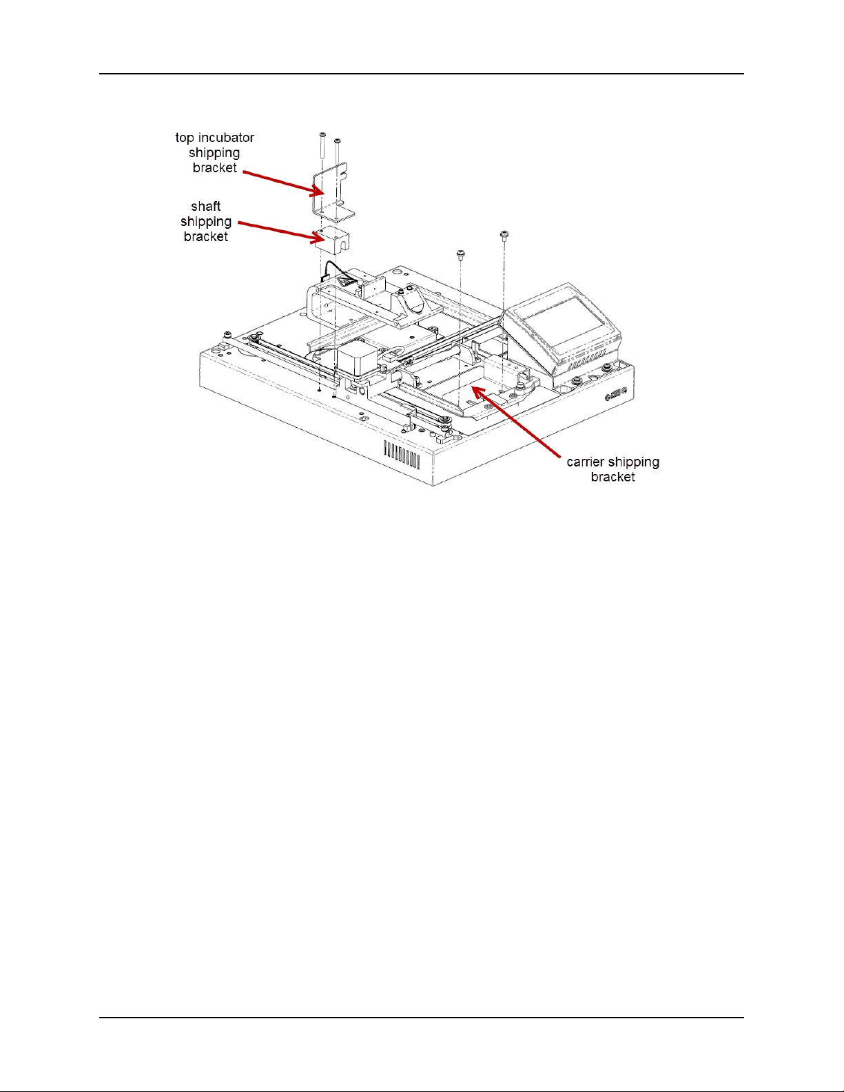
3. Remove the two screws on each of the shipping brackets, remove the brackets, and
store the screws in the holes on the brackets.
800 TS
Page 16
4 | Verify the Filter Wheel Contents
4. Store the shipping hardware in a safe place in case it is needed in the future.
5. If applicable (described in the next section), install the door now.
3. Verify the Filter Wheel Contents
The 800 TS ships with up to five preordered filters in the filter wheel. During installation, it
is good practice to verify the filters and their placement, and to confirm that the software
filter table matches the filter wheel’s configuration (discussed later). All five locations in
the wheel must contain either a filter or a plug.
Before continuing, obtain a clean, lint-free cloth.
BioTek Instruments, Inc.
Page 17
Verify the Filter Wheel Contents | 5
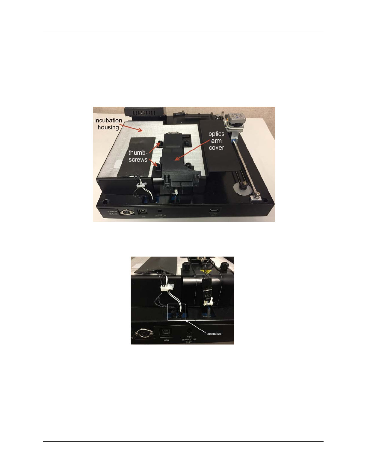
For models with incubation capability: You must first remove the incubation housing to
access the filter wheel.
1. With the top case removed from the reader (see Remove the Shipping Hardware
on page 3 for directions), remove the four thumbscrews from the optic arm, and lift
the optic arm cover off (if equipped).
2. Disconnect the two connectors on the back of the incubation housing, then gently lift
the housing off of the reader.
800 TS
Page 18
6 | Verify the Filter Wheel Contents
To access the filter wheel:
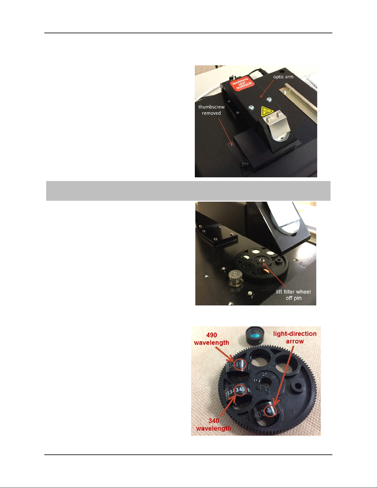
1. With the top case removed from the reader
(see Remove the Shipping Hardware on page 3
for directions), remove the four thumbscrews
from the filter wheel cover. This cover is directly
under the optics arm.
Note: The filters are not held in place and fall out of the wheel easily, so make sure to have a clean, lintfree cloth in place before turning over the filter wheel.
2. Lift the filter wheel off its pin, then remove
the filters by turning the wheel upside down
over a clean, lint-free cloth. Write down which
filters are installed in the filter wheel and the
location of each filter. You will use this
information later to verify/edit the software
filter table.
Compare the filters with your model’s default
filters or with the purchase order if different
filters were ordered. Contact BioTek Customer
Care if you did not receive the expected
filters/plugs.
Each filter is labeled with a wavelength and an
arrow showing the light direction. The arrows
must point downward when the filter wheel is
installed on the reader.
BioTek Instruments, Inc.
Page 19

Select an Appropriate Location | 7
3. When you are finished examining the filters,
replace the filters in the filter wheel, being
careful to insert them in the correct direction
(indicated by the arrow printed on the side of
each filter).
4. Replace the filter wheel on its pin, and then
replace the filter wheel cover using the four
thumbscrews removed during step 1.
5. Tape the door closed, if equipped.
6. Carefully turn the reader upside down over its
cover, and reattach the reader to the top cover
by replacing the six screws.
4. Select an Appropriate Location
Install the reader on a level, stable surface. Select an area where ambient temperatures
between 18°C (71.6°F) and 40°C (104°F) can be maintained.
The reader is sensitive to extreme environmental conditions. Avoid the following:
•
Excessive humidity.
Condensation directly on the sensitive electronic circuits can
cause the instrument to fail internal self-checks. The humidity must be in the range of
10–85%, non-condensing.
•
Excessive ambient light.
reducing its linear range.
•
Dust.
Readings may be affected by extraneous particles (such as dust) in the
Bright light may affect the reader’s optics and readings,
microplate wells. A clean work area is necessary to ensure accurate readings.
800 TS
Page 20

8 | Install the Power Supply
5. Install the Power Supply
Power Rating. The instrument must be connected to a power receptacle that
provides voltage and current within the specified rating for the system. Use of an
incompatible power receptacle may produce electrical shock and fire hazards.
Electrical Grounding. Never use a plug adapter to connect primary power to the
instrument. Use of an adapter disconnects the utility ground, creating a severe
shock hazard. Always connect the system power cord directly to an appropriate
receptacle with a functional ground.
a. Connect the power cord to the external power supply.
b. Locate the power inlet on the rear of the reader.
c. Plug the rounded end of the power supply's cord into the power inlet.
d. Plug the other end of the power cord into an appropriate power receptacle.
6. (Optional) Install Gen5 on the Host Computer
There is a certain sequence of events that must be followed to ensure that the
software is properly installed and configured. Please follow the instructions
provided in Gen5 Getting Started Guide to install the software.
BioTek Instruments, Inc.
Page 21

(Optional) Install the USB Driver | 17
7. (Optional) Install the USB Driver
Refer to the instructions that shipped with the Gen5 software to install the necessary
drivers. The driver must be installed on the computer before you connect the
instrument.
8. (Optional) Connect the Host Computer
The USB port is located on the rear of the reader.
1. Turn off the computer. If the reader is on, turn it off.
2. Using the supplied USB cable, connect the square end of the cable to the USB port on
the back of the reader.
3. Connect the other end of the cable to an available USB port on the computer.
9. Turn on the Reader
1. Locate the power on/off switch on the right side of the instrument, and turn on the
reader. The reader delays any action until the bulb has warmed up: three minutes for
narrow beam and UV models, and 30 seconds otherwise. Then the reader performs a
power-up system test.
If using Gen5, do not attempt to communicate with the reader until the system
test is finished.
2. When the system test is completed, the touchscreen displays its main screen.
800 TS
Page 22

18 | Set Date and Time on Touchscreen
10. Set Date and Time on Touchscreen
The date and time are included in the instrument’s system test report. Define these
settings now to ensure correct information when you perform step 14.
1. From the Main Menu, tap Instrument, the
Config tab, then the Time button
2. Tap the hour value, and use the keypad to
enter the correct time for both the hour and
minutes, then click OK.
Note: You can change just the minutes value: Tap
the minutes value and enter the correct time.
3. Tap the Date button.
4. Tap month, day, or year, and use the keypad
to set the current date. Tap OK when done.
11. Verify the Reader's Filter Table
Before using the 800 TS, verify that the filter table reflects the filters installed in the filter
wheel.
Important! The reader’s filter table must exactly match the contents of the installed
filter wheel.
BioTek Instruments, Inc.
Page 23

(Optional) Establish Communication | 19
the absorbance test plate setup screen.
1. From the Main Menu, tap Instrument, the
Config tab, and then Filter Table. Filter wheel
locations 1 through 5 are shown, with each
location’s filter value (in nm) or “plug” for a
blank filter.
2. Verify that the values match the contents of
the filter wheel. See the Installation chapter
for instructions for accessing the filter wheel.
3. To change the setting for a filter wheel
position, tap its value and use the keypad to
enter a wavelength value (in nm), or select
Plug. Tap OK when finished.
4. If you made any changes, tap Save in the
Installed Filters screen. The filter values are
now available for selection in protocols and
12. (Optional) Establish Communication
NOTE: Instrument must be at the Main Menu screen for Gen5 communication to occur.
1. On the host computer, start Gen5 and log in if prompted. The default System
Administrator password is admin.
2. From the Gen5 main screen, select System > Instrument Configuration and click Add.
3. Set the Reader Type to 800 TS.
4. Perform one of the following steps, as applicable:
•
Select
Plug & Play.
An 800 TS must be connected via USB to the computer and turned on to appear
in the Available Plug & Play Readers list.
•
Set the Com Port to the computer's COM port to which the reader is
connected.
800 TS
Page 24

20 | Run a System Test
The information can be found via the Windows Control Panel, under Ports in the
Hardware/Device Manager area of System Properties (e.g., Serial Port (COM5)).
5. To verify that Gen5 can communicate with the instrument, click Test Comm. If the
communication attempt is successful, Gen5 displays a success message. Return to
Gen5’s main screen.
Communication Errors
If the communication attempt is not successful, try the following:
•
Is the reader connected to the power supply and turned on?
•
Is the communication cable firmly attached to both the reader and the
computer?
•
Did you select the correct Reader Type in Gen5?
•
Try a different COM Port in Gen5 or use Plug & Play.
•
Did you install the USB driver software?
•
Is the touchscreen at the Main Menu?
If you remain unable to get Gen5 and the reader to communicate with each other,
contact BioTek’s Technical Assistance Center.
13. Run a System Test
Running a system test will confirm that the reader is functioning properly, or will provide
an error code if a problem is detected.
Using the Touchscreen
1. If the reader is equipped with an incubator, turn it on.
a. On the Main Menu, tap the temperature display (circled in the following image).
When the incubator is turned on, the dashes are replaced by the reader’s internal
temperature, in degrees Celsius.
BioTek Instruments, Inc.
Page 25

Run a System Test | 21
b. On the Incubate tab of the Quick Menu screen, turn on the Temperature Control and
enter a setpoint of at least 37°C, then tap Home to return to the Main Menu.
c. Wait for the temperature display to reach the defined setpoint before continuing.
2. From the Main Menu, tap Instrument > Options.
800 TS
Page 26

22 | Run a System Test
3. Under System test, tap Start.
4. When the test finishes, tap USB Report to save the test results to a USB flash drive,
Print to print the test results, or Exit to close the screen.
5. If applicable, turn off incubator.
Using Gen5
1. If necessary, launch Gen5 and turn on the incubator:
•
From the Gen5 main screen, select
•
Click the
•
Enter a Requested temperature of at least 37°C and click On.
•
Wait until the incubator temperature reaches the set point before continuing.
Pre-Heating
tab.
2. Return to Gen5’s main view and select System > Diagnostics > Run System Test. If
prompted to select a reader, select 800 TS and click OK.
System > Instrument Control > 800 TS.
3. If a message appears, stating that the reader has a pending system test report, click OK,
then click Close.
The reader ran a "power-up" system test, but that test did not include verifying
that the incubator reaches a set temperature. Therefore, you will run another
system test.
Again, select System > Diagnostics > Run System Test. If prompted to select a reader, select 800
TS and click OK.
4. When the test is completed, a dialog requesting additional information appears. Enter
the information and click OK.
5. The results report appears and should contain the text "SYSTEM TEST PASS."
• If required, print the report and store it with your records.
• The Gen5 software stores system test information in its database; you can
retrieve it at any time.
•
You can save the system test report as a text file: click Save As in the System
Test Results dialog.
BioTek Instruments, Inc.
Page 27

as a whole set under this part number and cannot be ordered separately.
6. If applicable, turn off the incubator:
•
Select
•
Click the
•
Return to Gen5’s main view.
System > Instrument Control > 800 TS.
Pre-Heating
tab and click
Repackaging and Shipping Instructions
Important! Please read all of the information provided below
If the reader has been exposed to potentially hazardous material, decontaminate
it to minimize the risk to all who come in contact with the reader during shipping,
handling, and servicing. Decontamination prior to shipping is required by the U.S
Department of Transportation regulations. See the As-Needed Maintenance
chapter for decontamination instructions.
Remove any labware from the carrier before shipment. Spilled fluids can
contaminate the optics and damage the instrument.
before preparing the 800 TS for shipment.
Repackaging and Shipping Instructions | 23
Off.
The instrument’s packaging design is subject to change. If the instructions in this
section do not appear to apply to the packaging materials you are using, please
contact BioTek’s Technical Assistance Center for guidance.
Replace the shipping hardware before repackaging the instrument. Please
800 TS
contact BioTek if you need to replace any of these items:
•
Carrier shipping bracket (PN 1560517)
•
Carrier shipping bracket screws (PN 19668)
•
Shaft shipping bracket (PN 7332041)
•
Shaft shipping bracket screws (PN 19337)
•
If applicable, top incubation shipping bracket (PN 1562072)
If you need to ship the 800 TS to BioTek for service or repair, be sure to use the
BioTek-supplied packaging materials. Other forms of commercially available
packaging are not recommended and can void the warranty.
If the packaging materials have been damaged or lost, or if the same set has
been used more than four times, contact BioTek to order replacement part
number 1563000. The shipping box, accessories box, and foam trays are included
Page 28

BioTek Instruments, Inc.
24 | Repackaging and Shipping Instructions
Page 29

Getting Started
Page 30

26 | Overview
Overview
The 800 TS is a compact, filter-based, single-channel absorbance microplate reader. All
models are equipped with a touchscreen interface and support endpoint dual-wavelength
reads from 400-750 nm on standard 6- to 96-well plates. The narrow beam (NB) model
supports 384-well plates. UV models support a measurement range from 340-750 nm.
Some models offer incubation to 50˚C and/or linear plate shaking.
Basic data analysis, reporting, and exporting are provided via the touchscreen. With
optional Gen5 software, kinetic and well area scanning read modes are supported, along
with BioCell and 60-, 72-, and 96-well Terasaki plates. Gen5 also offers extensive data
analysis and reporting and exporting capabilities. The reader is available in five models.
The filter wheel contains up to five filters and is user accessible. For models with fewer
than five filters, removable plugs are installed in the empty wheel locations.
The 800TS and 800TSI models use a tungsten bulb as their light source. The other
models, 800TSUV, 800TSUVI, and 800TSNB, use a halogen bulb.
Refer to the 800 TS Operator’s Manual for recommendation for ensuring optimum
performance.
BioTek Instruments, Inc.
Page 31

External Components
1
Microplate carrier
| 27
2
Touchscreen
3
Power switch
4
USB flash drive port for USB flash drive
Note that the photo does not show the door.
800 TS
Page 32

28 | External Components
Rear ports on a reader without incubation capability
1
Power port
2
USB port
3
DO NOT USE! For BioTek Service only
4
USB port for printer
Rear ports on a reader with incubation capability
1
Power port
2
USB port
3
DO NOT USE! For BioTek Service only
4
USB port for printer
BioTek Instruments, Inc.
Page 33

Operate the Reader Using the Touchscreen| 29
Operate the Reader Using the Touchscreen
General Information
Do not use a sharp stylus or pencil on the touchscreen. Doing so can damage the
touchscreen's surface. You can use a stylus designed for capacitive touchscreens.
When you turn on the 800 TS, the touchscreen turns on automatically and opens to the
Main Menu after the start-up system test and bulb warm-up. The length of the bulb warmup process varies from three minutes for narrow beam and UV models, and 30 seconds
otherwise.
•
To select a button or check box or to activate a tab, tap the item once.
•
To return to the Main Menu from any other screen, tap
corner.
•
For instructions on cleaning the touchscreen, see the Maintenance chapter.
Home
in the top-left
Note:
the Instrument or Quick Menu. Note that if you turn off the bulb, the reader will go
through the bulb warm-up process when you turn the bulb back on (three minutes for
narrow beam and UV models, and 30 seconds otherwise).
Main Menu
To preserve the life of the bulb, turn it off when not needed by tapping
in
800 TS
Page 34

30 | Operate the Reader Using the Touchscreen
800TSI and 800TSUVI models: When the incubator is turned on, the reader’s internal
temperature is displayed at the top of the screen, as shown above. When the incubator
is off, dashes are displayed.
The left side of the Main Menu screen lists the assay protocols defined on the reader. As
shipped, the reader contains no protocols and the list is empty. Up to 40 uniquely named
protocols can be programmed and stored. Tap Next to scroll through the list.
On the right side of the Main Menu are the following options:
•
Quick:
Define and run a simple single- or dual-wavelength protocol. You can
select the primary and secondary wavelength values and the plate type. If
applicable to your reader model, shake and/or incubate options are available.
•
Protocol:
Edit, create (and save), delete, and copy protocols. You can define
the protocol name; select the primary and secondary wavelength values, read
speed, and plate type; and define blank well(s). If applicable to your reader
mode, shake options
are available.
The reader automatically performs delta OD and blank subtraction. To select the
dataset(s) for print or export, tap Instrument and then the Output tab.
•
Results:
reader (for the 12 most recently run protocols).
•
Instrument:
results output criteria; run an Absorbance Plate Test; and more.
View and optionally print/export measurement data stored on the
Configure the reader, printer, and USB flash drive settings; define
Configure Your 800 TS
After you install the reader, and before you use it to create and run protocols, perform the
tasks in this section to define important instrument settings.
Set the Time and Date
When you turn on the 800 TS for the first time, set or confirm the date and time at your
location.
BioTek Instruments, Inc.
Page 35

Operate the Reader Using the Touchscreen| 31
1. From the Main Menu, tap Instrument, the Config tab,
then the Time button.
2. Tap the hour value, and use the keypad to enter the
correct time for both the hour and minutes, then click OK
.
Note: You can change just the minutes value: Tap the
minutes value and enter the correct time.
3. Tap the Date button.
4. Tap month, day, or year, and use the keypad to set the
current date. Tap OK when done.
Verify or Change the Reader’s Filter Table
Important! The reader’s filter table must exactly match the contents of the installed
filter wheel.
800 TS
Page 36

32 | Operate the Reader Using the Touchscreen
Define Regional Settings
1. From the Main Menu, tap Instrument, the Config tab,
and then Filter Table. Filter wheel locations 1 through 5
are shown, with each location’s filter value (in nm) or
“plug” for a blank filter.
2. Verify that the values match the contents of the filter
wheel. See the Installation chapter for instructions for
accessing the filter wheel.
3. To change the setting for a filter wheel position, tap its
value and use the keypad to enter a wavelength value (in
nm), or select Plug. Tap OK when finished.
4. If you made any changes, tap Save in the Installed Filters
screen. The filter values are now available for selection in
protocols and the absorbance test plate setup screen.
1. From the Main Menu, tap Instrument, the Config tab,
and then Regional Settings.
Define Output Formats for Measurement Data
2. Tap to toggle between:
-Time format: AM/PM or 24 hour
-Date format: mm/dd/yyyy or dd/mm/yyyy
-Decimal symbol: period or comma (Note: This setting
does not apply to the system test report content.)
-List separator: comma or semicolon (used in the
exported report .csv file)
If you want to send results to a printer connected to the
reader:
1. From the Main Menu, tap Instrument, then tap the
Output tab.
2. Toggle the Printer button to Enabled, and select the
data to be included on the printout (you can select more
than one):
BioTek Instruments, Inc.
Page 37

Operate the Reader Using the Touchscreen| 33
•
Raw OD
: The raw measurement value for each well.
•
Delta OD
: Applicable only when a secondary wavelength is selected. This is the calculated
value for each well of the primary wavelength measurement minus secondary wavelength
measurement.
Blanked
•
. The calculated value for each well, either Raw OD minus the average of the
blank wells for single-wavelength reads or Delta OD minus the average of the blank wells
for dual
wavelength reads.
If you want to send results to a USB flash drive inserted in the reader, on the Output tab,
toggle the USB Flash Drive button among the options.
•
Report
: Generates a CSV file containing the measurement values (with Raw OD/Delta
OD/blanked values, as applicable). This file can be opened in Excel or other spreadsheet
software.
Gen5 Input
•
: Generates a text file that can be opened in Gen5 using the Read from File option.
This file contains only raw data, not delta ODs or blanks.
See page 92 for sample CSV and text files.
Define and Start a Quick Protocol
1. From the Main Menu, tap Quick.
2. In the Quick Menu, set the Primary and, if
applicable, Secondary wavelengths and plate type,
then tap Start.
Note: This screenshot is from an instrument
Note: You cannot define blank wells for a Quick read.
When the read is finished, the results are displayed.
Tap Output to send results to the printer or USB flash
drive.
with incubation and shake capabilities.
Create and Save a Protocol
The maximum number of uniquely named protocols that can be saved on the
touchscreen at the same time is 40.
Create a Protocol
1. From the home screen, tap Protocol, then tap Create.
800 TS
Page 38

34 | Operate the Reader Using the Touchscreen
2. Use the onscreen keyboard to enter a name for the
protocol, then tap OK.
Note: The <-- key circled in the figure is the backspace
key.
3. Toggle through the values to set a Primary
wavelength.
4. If applicable, toggle through the values to set a
Secondary wavelength. Otherwise, leave as “---.”
Note: The reader automatically performs Delta OD
subtraction.
5. Toggle to set a read speed: Normal, Rapid, or
Note that the Options tab is not displayed on all
instruments.
6.
Toggle to set the plate type: 6-, 12-, 24-, 48-, 96, or 384*-well microplates. Note: Only full plate
Sweep. See the Throughput values associated with
each read speed type in the Specifications appendix.
Note that Sweep is not available on the NB model.
reads are supported on the touchscreen. To read a partial plate, you must use Gen5.
7. If applicable, tap the Blank tab to add blank wells.
a. In the Blank Well screen, use the keypad to enter which well should be blank, then
tap OK.
b. Tap Add to enter more blank wells, up to 12.
8. If the reader is equipped with shake capability, tap Options and define a shake step, if
desired. Set the shake’s duration using the keypad and intensity by toggling through the
options.
9. Tap Save. The protocol now appears in the protocol list.
*Not all instruments support 384-well microplates.
BioTek Instruments, Inc.
Page 39

Operate the Reader Using the Touchscreen| 35
Start a Protocol
For instruments equipped with incubation capability: To perform incubation during
measurement, either turn on incubation from the Incubate tab (Quick Menu) or tap the
temperature to the left of the Run Protocol (in a defined protocol).
The onboard storage for the touchscreen can accommodate data for up to 12
microplate reads. The data is stored by date and time, not by filename. If 12 results are
already in onboard storage, the next read data saved will overwrite the oldest of the
saved results.
Note that only plate read results are saved. System Test and Absorbance Plate Test
results are not saved; they can only be exported to USB flash drive or printed.
1. From the Main Menu, tap the protocol you
want to run. The Run Protocol screen opens,
displaying the protocol’s parameters.
2. Place the microplate on the carrier, and tap
Start. When the read is finished, the results are
displayed. Tap Output to send results to the
printer or USB flash drive.
Change the Protocol Display Order
1. From the Main Menu, tap Instrument, then tap the Options tab.
2. In the Protocol display order field, select Alphabetically or Last accessed first.
Edit, Delete, or Copy a Protocol
Edit a Protocol
1. From the Main Menu, tap Protocol.
2. Tap the protocol that you want to modify, then tap Edit.
3. Make any desired changes, then tap Save.
800 TS
Page 40

BioTek Instruments, Inc.
36 | Operate the Reader Using Gen5 Software
Delete a Protocol
1. From the Main Menu, tap Protocol.
2. Tap the protocol you want to delete, then tap Delete.
Copy a Protocol
Copying an existing protocol and then editing it is a quick way to create a new protocol.
1. In the Main Menu, select the protocol you want to copy, then tap Copy.
2. You are prompted to enter a name for the copied protocol.
3. Make any desired changes, then tap Save.
View or Output Results Stored on the Reader
1. In the Main Menu, tap Results, then select the date/time of the read for which you
want to view or output results. The results are displayed on the touchscreen.
2. Tap Output. The results are printed and/or saved to the USB flash drive, depending
on the output format you selected.
Operate the Reader Using Gen5 Software
Gen5 RC (Reader Control) software is supplied with the 800 TS. This edition supports
only instrument control and data reporting/exporting. To perform kinetic reads, data
reduction, and custom exports, a software upgrade is required; contact BioTek
Customer Care.
BioTek Gen5 software supports all 800 TS reader models. Use Gen5 to control the reader;
perform data reduction and analysis on the measurement values; print or export results;
and more. This section provides brief instructions for working with Gen5 to create
protocols and experiments and read plates. Refer to the Gen5 Help system for more
information.
Page 41

Maintenance
Page 42

38 | Maintenance Overview
Task
Daily
Quarterly
As Needed
All models:
Clean exposed surfaces
x x
Inspect/clean touchscreen
x
Inspect/clean the wavelength filters
x
Decontamination
Before shipment or storage
handling contaminated instruments. Gloved
Maintenance Overview
A general maintenance regimen for all 800 TS models includes periodically cleaning all
exposed surfaces and decontaminating the instrument before storage or shipment.
Schedule
The risk and performance factors associated with your assays may require performing some of all of
the procedures more frequently than presented in this schedule.
Warnings and Precautions
Read the following before performing any maintenance procedures:
Warning! Internal Voltage. Turn off and unplug the instrument for all maintenance
and repair operations.
Important! Do not immerse the instrument, spray it with liquid, or use a drippingwet cloth on it. Do not allow water or other cleaning solution to run into the
interior of the instrument. If this happens, contact the BioTek Service Department.
Do not soak the touchscreen! This will cause damage. Moisten a clean cloth with
deionized or distilled water and wipe the touchscreen. Dry immediately with a
clean, dry cloth.
Important! Do not apply lubricants to the microplate carrier or carrier track.
Lubricant attracts dust and other particles, which may obstruct the carrier path and
cause errors.
Warning! Wear protective gloves when
hands should be considered contaminated at all times; keep gloved hands away
from eyes, mouth, nose, and ears.
BioTek Instruments, Inc.
Page 43

Clean Exposed Surfaces | 39
Warning! Mucous membranes are considered prime entry routes for infectious
agents. Wear eye protection and a surgical mask when there is a possibility of
aerosol contamination. Intact skin is generally considered an effective barrier
against infectious organisms; however, small abrasions and cuts may not always be
visible. Wear protective gloves when handling contaminated instruments.
Clean Exposed Surfaces
This procedure is for the housing of the 800 TS instrument. See "Clean the Touch
Screen" on page 39 for the cleaning procedure for the touchscreen.
Exposed surfaces may be cleaned (not decontaminated) with a cloth moistened (not soaked)
with water or water and a mild detergent. You’ll need:
•
Mild detergent
•
Deionized or distilled water
•
Clean, lint-free cotton cloths
1. Turn off and unplug the instrument.
2. Wet a clean cotton cloth with water, or with water and mild detergent, then
thoroughly wring out the cloth so that liquid does not drip from it.
3. Wipe the plate carrier, the inside of the plate carrier door (if equipped), and all exposed
surfaces of the instrument.
4. If detergent was used, wipe all surfaces with a cloth moistened with water.
5. Use a clean, dry, lint-free cloth to dry all wet surfaces.
Clean the Touchscreen
Important! Never spray solutions directly on the touchscreen.
Materials
Use the following products to safely clean the touchscreen:
•
Deionized or distilled water
•
Dish soap or other mild cleaner
•
Lintfree disposable towels
800 TS
Page 44

40 | Decontamination
Avoid the following cleaning products:
•
Strong solvents, such as alcohol, acetone, ammonium chloride,
methylene
chloride, and hydrocarbons, which can permanently damage
the surface of the touchscreen.
•
Fibrous materials, such as paper towels, which can scratch the
touchscreen. Over time, dirt particles and cleaning agents can get
trapped
in the scratches.
Procedure
Important! Never spray solutions directly on the touchscreen.
Turn off and unplug the instrument.
1. Moisten a clean, lint-free disposable cloth with water, or with water and mild detergent,
then thoroughly wring it out so that liquid does not drip from it. Do not soak the cloth.
2. Wipe the touch screen gently with the moist cloth.
3. If detergent was used, wipe the touchscreen with a cloth moistened with water.
4. Dry the screen gently using another cloth.
Decontamination
Any laboratory instrument that has been used for research or clinical analysis is considered
a biohazard and requires decontamination prior to handling.
Decontamination minimizes the risk to all who come into contact with the instrument
during shipping, handling, and servicing. Decontamination is required by the U.S.
Department of Transportation regulations.
Persons performing the decontamination process must be familiar with the basic setup and
operation of the instrument.
Turn off and unplug the instrument for the decontamination procedure.
BioTek Instruments, Inc., recommends the use of the following decontamination
solutions and methods based on our knowledge of the instrument and
recommendations of the Centers for Disease Control and Prevention (CDC). Neither
BioTek nor the CDC assumes any liability for the adequacy of these solutions and
methods. Each laboratory must ensure that decontamination procedures are
adequate for the biohazard(s) they handle.
BioTek Instruments, Inc.
Page 45

Wear prophylactic gloves when handling contaminated instruments. Gloved hands
should be considered contaminated at all times; keep gloved hands away from
eyes, mouth, and nose. Eating and drinking while decontaminating instruments is
not advised.
Mucous membranes are considered prime entry routes for infectious agents. Wear
eye protection and a surgical mask when there is a possibility of aerosol
contamination. Intact skin is generally considered an effective barrier against
infectious organisms; however, small abrasions and cuts may not always be visible.
Wear protective gloves when performing the decontamination procedure.
Decontaminating the Reader Housing
Required Materials
•
Sodium hypochlorite (NaClO, or bleach)
•
70% isopropyl alcohol (as an alternative to bleach)
•
Deionized or distilled water
Decontamination | 41
•
Safety glasses
•
Surgical mask
•
Protective gloves
•
Lab coat
•
Biohazard trash bags
•
125-mL beakers
•
Clean, lint-free cotton cloths
Procedure
1. Turn off and unplug the reader from the power supply.
2. Prepare an aqueous solution of 0.5% sodium hypochlorite (NaClO, or bleach). If the
effects of bleach are a concern, 70% isopropyl alcohol may be used.
Check the percent NaClO of the bleach you are using. Commercial bleach is typically
10.0% NaClO; prepare a 1:20 dilution. Household bleach is typically 5.0% NaClO;
prepare a 1:10 dilution.
3. Moisten a clean, lint-free cloth with the bleach solution, then thoroughly wring it out so
that liquid does not drip from it. Do not soak the cloth.
4. Wipe the plate carrier and all exposed surfaces of the instrument, except the touch
800 TS
screen (if equipped).
Page 46

42 | Filter Storage and Handling
5. Allow the instrument to dry for 20 minutes for thorough decontamination by the bleach.
6. Moisten a cloth with deionized or distilled water and wipe all surfaces of the instrument
that have been cleaned with the bleach solution.
7. Use a clean, dry lint-free cloth to dry all wet surfaces.
8. Discard the used gloves and cloths, using a biohazard trash bag and an approved
biohazard container.
Decontaminating the Touchscreen
When decontaminating the 800 TS, as described on page 47, do not spray the bleach
solution on the touchscreen. Avoid fibrous materials that can scratch the surface. Do not
use a stronger bleach solution or cleaning solvent than recommended.
Filter Storage and Handling
To properly store interference filters during extended periods of non-use, package the
filters in a light-tight envelope or container, away from high humidity. This will ensure the
longest life for the filters. When handling the filters, keep the surfaces clean from
fingerprints and debris by simply wiping with a lens tissue or other lint-free cloth.
When changing or replacing filters, it is critical that the filters be placed in the
filter wheel in the correct orientation, with the light-direction arrow pointing
downward. Also, the reader or Gen5 software filter table must exactly match the
contents of the filter wheel.
1. Use a clean, dry lint-free cloth to dry all wet surfaces.
2. Discard the used gloves and cloths, using a biohazard trash bag and an approved
biohazard container.
Decontaminating the Touchscreen
When decontaminating the 800 TS, as described on page 47, do not spray the bleach
solution on the touchscreen. Avoid fibrous materials that can scratch the surface. Do not
use a stronger bleach solution or cleaning solvent than recommended.
Filter Storage and Handling
To properly store interference filters during extended periods of non-use, package the
filters in a light-tight envelope or container, away from high humidity. This will ensure the
longest life for the filters. When handling the filters, keep the surfaces clean from
fingerprints and debris by simply wiping with a lens tissue or other lint-free cloth.
BioTek Instruments, Inc.
Page 47

Filter Storage and Handling | 43
When changing or replacing filters, it is critical that the filters be placed in the
filter wheel in the correct orientation, with the light-direction arrow pointing
downward. Also, the reader or Gen5 software filter table must exactly match the
contents of the filter wheel.
800 TS
Page 48

BioTek Instruments, Inc.
44 | Filter Storage and Handling
Page 49

Instrument Testing
Page 50

46 | System Test
System Test
Each time the 800 TS is turned on, it automatically performs a series of tests on the
reader’s motors, lamp, and optical systems. If all tests pass, the microplate carrier moves
to its forward position and the Main Menu appears on the touchscreen.
If any test results do not meet the internally coded Failure Mode Effects Analysis (FMEA)
criteria established by BioTek, the reader beeps repeatedly and an error message appears
on the touchscreen. If this occurs, tap OK on the touchscreen to stop the beeping. If
necessary, initiate another system test using Gen5 or the touchscreen to try to retrieve an
error code from the reader.
Absorbance Test Plates
Absorbance Test Plate PN 7260522 uses NIST-traceable neutral density filters to confirm
absorbance specifications in the visible range (400–800 nm). This test plate also contains
precision-machined holes to verify mechanical alignment. Absorbance Test Plate PN
7260551 uses NIST-traceable neutral density filters to confirm absorbance specifications in
the UV range (340 nm).
Define the Absorbance Test Plate Parameters
Using the Touchscreen
1. Obtain the current Test Plate Calibration Certificate.
2. From the Main Menu, tap Instrument, then tap Test Plate.
3. Tap Test Plate Certificate and enter the plate’s serial number and Next Calibration Due
date, then tap Back to return to the Test Plate tab.
4. The wavelength selection buttons reflect the filters installed in the reader. Tap each
button, and enter the OD Standard values from the Calibration Certificate into the grid.
Make sure you enter the correct value for each well/wavelength combination.
Using Gen5
1. Obtain the current Test Plate Calibration Certificate.
2. Start Gen5, and select System > Diagnostics > Test Plates > Add/Modify Plates.
3. Click Add. The Absorbance Test Plate dialog appears.
4. Select the appropriate Plate Type, and then enter the plate's serial number.
5. Enter the Last Certification and Next Certification dates from the calibration label on
the Test Plate.
6. If the wavelength values in the top row of the grid in Gen5 are appropriate for your
tests, enter the OD Standard values from the Calibration Certificate into the grid. Make
sure you enter the correct value for each well/wavelength combination.
BioTek Instrument, Inc.
Page 51

Absorbance Test Plates | 47
If you need to change the wavelength values, click Wavelength List. Add, change, or
delete the values as needed and click OK.
7. Review all of the values that you entered. When finished, click OK to save the
information.
Running the Absorbance Plate Test
Using the Touchscreen
1. Place the Absorbance Test Plate on the microplate carrier, with well A1 in the proper
location.
2. From the Main Menu, tap Instrument and then Test Plate.
3. Tap a Wavelength Selection button, then tap Start.
4. When the test is complete, choose an Output option (Print or USB Report), or tap Exit
to return to the Main Menu.
Using Gen5
1. From the Gen5 main screen, click System > Diagnostics > Test Plates > Run. If
prompted, select the desired Test Plate and click OK.
2. When the Absorbance Test Plate Options dialog appears, enter any required
information.
3. Highlight the wavelength(s) to be included in this test.
You need to select only those wavelengths most appropriate for your use of the reader.
4. (Optional) Enter a comment.
5. Click Start Test.
6. Place the Absorbance Test Plate on the microplate carrier, with well A1 in the proper
location.
7. Click OK to run the test.
8. When the test is complete, the results report appears. Scroll through the report; every
result should show “PASS”.
800 TS
Page 52

48 | Liquid Tests
Liquid Tests
Be sure to use a new microplate, because fingerprints or scratches may cause variations
in readings.
Materials
•
New 96-well, clear, flat-bottom microplate (Corning Costar #3590 recommended)
•
Stock Solution A or B, which may be formulated by diluting a dye solution available
Solution A
from BioTek (A) or from the materials listed below (B).
•
BioTek QC Check Solution No. 1 (PN 7120779, 25 mL; or 7120782, 125 mL)
•
Deionized water
•
5-mL Class A volumetric pipette
•
100-mL volumetric flask
1. Pipette a 5-mL aliquot of BioTek QC Check Solution No. 1 into a 100-mL volumetric flask.
2. Add 95 mL of DI water; cap and shake well. The solution should measure approximately
2.000 OD when using 200 µL in a flat-bottom microwell.
Solution B
•
Deionized water
•
FD&C Yellow No. 5 dye powder (typically 90% pure)
•
Tween 20 (polyoxyethylene (20) sorbitan monolaurate) or BioTek wetting agent, PN
7773002 (a 10% Tween solution)
•
Precision balance with capacity of 100 g minimum and readability of 0.001 g
•
Liter volumetric flask
•
Weigh boat
1. Weigh out 0.092 gram of FD&C No. 5 yellow dye powder into a weigh boat.
2. Rinse the contents into a 1-liter volumetric flask.
3. Add 0.5 mL of Tween 20, or 5 mL of BioTek’s wetting agent.
4. Make up to 1 liter with DI water; cap and shake well.
BioTek Instrument, Inc.
Page 53

Procedure
Be sure to use a new microplate. Debris, fingerprints, or scratches may cause
variations in readings.
1. Using freshly prepared stock solution (Solution A or B), prepare a 1:2 dilution using
deionized water (one part stock, one part deionized water; the resulting solution is a 1:2
dilution). The concentrated stock solution should have an optical density of
approximately 2.000 OD or lower.
2. Pipette 200 µL of the stock solution into column 1.
3. Pipette 200 µL of the diluted solution into column 2.
After pipetting the diluted test solution into the microplate and before reading
the plate, we strongly recommend shaking the plate for four minutes. This will
allow any air bubbles in the solution to settle and the meniscus to stabilize.
Alternatively, wait 20 minutes after pipetting the test solution before reading the
plate.
Liquid Tests | 49
4. Using either the touchscreen or Gen5, read the microplate five times at 405
nm using the Normal Read Speed. When prompted, rotate the plate 180
degrees and read the plate five more time (“Turnaround” plate position), saving
the data after each read.
5. Print the ten sets of raw data, (from the touchscreen) send it to the USB flash
drive for use in another program, or (from Gen5) export it to an Excel
spreadsheet.
Calculations
Absorbance Liquid Test 1
Accuracy Specification:
± 1.0% ± 0.010 OD from 0.000 to 2.000 OD
Repeatability Specification:
± 0.5% ± 0.005 OD from 0.000 to 2.000 OD
1. The plate is read five times in the “Normal” position at 405 nm. Calculate the Mean OD
and Standard Deviation of those five reads for each well in columns 1 and 2.
2. For each well in columns 1 and 2, calculate the Allowed Deviation using the
Repeatability specification for a 96-well plate (Mean OD x 0.05 + 0.005). For each well,
its Standard Deviation should be less than its Allowed Deviation.
800 TS
Page 54

50 | Liquid Tests
Example: Five readings in well A1 of 0.802, 0.802, 0.799, 0.798, and 0.801 result in a
Mean of 0.8004 and a Standard Deviation of 0.0018. The Mean multiplied by 0.5%
(0.8004 * 0.005) equals 0.004, and when added to 0.005 equals 0.009; this is the Allowed
Deviation for well A1. Since the Standard Deviation for well A1 is less than this value, the
well meets the test criteria.
3. The plate is read five times in the “Turnaround” position at 405 nm. Calculate the Mean
OD of those five reads for each well in columns 11 and 12.
4. Perform a mathematical comparison of the Mean values for each well in its Normal and
Turnaround positions (that is, compare A1 to H12, A2 to H11, B1 to G12,… H2 to A11). To
pass the test, the differences in the compared Mean values must be within the Accuracy
specification for a 96-well microplate.
Example: If the Mean value for well A1 in the Normal position is 1.902 with a specified
accuracy of ±1.0% ±0.010 OD, then the expected range for the Mean of the well in its
Turnaround (H12) position is 1.873 to 1.931 OD. 1.902 x 0.010 + 0.010 = 0.029; 1.902 -
0.029 = 1.873; 1.902 + 0.029 = 1.931.
BioTek Instrument, Inc.
Page 55

Specifications
Page 56

52 | General Specifications
General Specifications
Microplates
The 800 TS accommodates standard 6-, 12-, 24-, 48-, 96-, and (with the NB model) 384-well microplates
with 128 x 86 mm geometry and, if using Gen5 software with the NB model, 60-, 75-, and 96-well
Terasaki plates and BioCell vessels.
Maximum plate height: 0.90" (22.86 mm)
Hardware and Environmental
Light Source
800TS/800TSI models: Tungsten gas-filled bulb.
800TSUV/800TSUVI/800TSNB models: Halogen bulb
Dimensions 16.5" D x 15" W x 7" H (41.9 x 38.1 x 17.8 cm)
Weight: < 22 lbs (10 kg)
Environment: Operational temperature range: 18° to 40°C
Humidity: 10% to 85% relative humidity (non-condensing)
Power Supply: 24-volt DC power supply compatible with 100–240 V AC @50–60 Hz
Power Consumption:
40W maximum, non-incubated models; 150W maximum, incubated
models
Temperature control for 800TSI model: 6°C over ambient to 50°C.
Incubation:
Temperature control for 800TSUVI model: 8°C over ambient to 50°C
Temperature stability and uniformity is ± 0.5°C across the plate @ 37°C.
BioTek Instruments, Inc.
Page 57

Absorbance Specifications
Standard Models (800TS/800TSI)
Wavelength Range: 400 nm to 750 nm
Absorbance Measurement Range
Normal Read Mode: 0.000 to 4.000 OD
Rapid Read Mode: 0.000 to 4.000 OD
Sweep Read Mode: 0.000 to 3.000 OD
Absorbance Resolution
0.001 OD when operated in standalone mode
0.0001 OD when operated with Gen5
General Specifications | 53
Accuracy
Normal Read Mode: ±1.0% ±0.010 OD from 0.000 to 2.000 OD @ 405 nm
Rapid Read Mode: ±2.0% ±0.020 OD from 0.000 to 2.000 OD @ 405 nm
Sweep Read Mode: ±1.0% ±0.020 OD from 0.000 to 1.000 OD @ 405 nm
Linearity
Normal Read Mode: ±1.0% ±0.010 OD from 0.000 to 2.000 OD @ 405 nm
±3.0% ±0.010 OD from 2.000 to 3.000 OD @ 450 nm
Rapid Read Mode: ±2.0% ± 0.010 OD from 0.000 to 2.000 OD @ 405 nm
Sweep Read Mode: ± 1.0% ± 0.010 OD from 0.000 to 1.000 OD @ 405 nm
Repeatability (STD)
Normal Read Mode: ± 0.5% ± 0.005 OD from 0.000 to 2.000 OD @ 405 nm
Rapid Read Mode: ± 1.0% ± 0.010 OD from 0.000 to 2.000 OD @ 405 nm
Sweep Read Mode: ± 2.0% ± 0.020 OD from 0.000 to 1.000 OD @ 405 nm
800 TS
Page 58

54 | General Specifications
Throughput
From carrier start to carrier stop:
96-Well, Single Wavelength, Normal Read Mode: 39 seconds
96-Well, Dual Wavelength, Normal Read Mode: 73 seconds
96-Well, Single Wavelength, Rapid Read Mode: 26 seconds
96-Well, Single Wavelength, Sweep Read Mode: 18 seconds
Ultraviolet (UV) Models (800TSUV/800TSUVI)
Wavelength Range: 340 nm to 750 nm
Absorbance Measurement Range
Normal and Rapid Read Mode (340 nm–399 nm): 0.000 to 4.000 OD
Normal and Rapid Read Mode (400 nm–750 nm): 0.000 to 4.000 OD
Sweep Read Mode (400 nm–750 nm): 0.000 to 3.000 OD
Absorbance Resolution
0.001 OD when operated in standalone mode
0.0001 OD when operated with Gen5
Accuracy (340 nm to 399 nm)
Normal Read Mode: ±2.0% ± 0.010 OD from 0.000 to 2.000 OD @ 340 nm
Rapid Read Mode: ±2.5% ± 0.020 OD from 0.000 to 2.000 OD @ 340 nm
Accuracy (400 nm to 750 nm)
Normal Read Mode: ±1.0% ± 0.010 OD from 0.000 to 2.000 OD @ 405 nm
Rapid Read Mode: ±2.0% ± 0.020 OD from 0.000 to 2.000 OD @ 405 nm
Sweep Read Mode: ±1.0% ±0.020 OD from 0.000 to 1.000 OD @ 405 nm
Linearity (340 nm to 399 nm)
Normal Read Mode: ±2.5% ± 0.010 OD from 0.000 to 2.000 OD @ 340 nm
Rapid Read Mode: ±2.5% ± 0.010 OD from 0.000 to 2.000 OD @ 340 nm
BioTek Instruments, Inc.
Page 59

Linearity (400 nm to 750 nm)
Normal Read Mode: ±1.0% ± 0.010 OD from 0.000 to 2.000 OD @ 405 nm
±3.0% ± 0.010 OD from 2.000 OD to 3.000 OD @ 450 nm
Rapid Read Mode: ±2.0% ± 0.010 OD from 0.000 to 2.000 OD @ 405 nm
Sweep Read Mode: ±1.0% ± 0.010 OD from 0.000 to 1.000 OD @ 405 nm
Repeatability (340 nm to 399 nm)
Normal Read Mode: ±1.5% ± 0.005 OD from 0.000 to 2.000 OD @ 340 nm
Rapid Read Mode: ±2.0% ± 0.020 OD from 0.000 to 2.000 OD @ 340 nm
Repeatability (400 nm to 750 nm)
Normal Read Mode: ±0.5% ± 0.005 OD from 0.000 to 2.000 OD @ 405 nm
General Specifications | 55
Rapid Read Mode: ±1.0% ± 0.010 OD from 0.000 to 2.000 OD @ 405 nm
Sweep Read Mode: ±2.0% ± 0.020 OD from 0.000 to 1.000 OD @ 405 nm
Throughput
From carrier start to carrier stop:
96-Well, Single Wavelength, Normal Read Mode: 39 seconds
96-Well, Dual Wavelength, Normal Read Mode: 73 seconds
96-Well, Single Wavelength, Rapid Read Mode: 26 seconds
96-Well, Single Wavelength, Sweep Read Mode: 18 seconds
Narrow Bean (NB) Models (800TSNB)
Wavelength Range: 400 nm to 750 nm
Absorbance Measurement Range
Normal and Rapid Read Mode (96-well): 0.000 to 4.000 OD
Normal and Rapid Read Mode (384-well): 0.000 to 4.000 OD
800 TS
Page 60

BioTek Instruments, Inc.
56 | General Specifications
Absorbance Resolution
0.001 OD when operated in standalone mode
0.0001 OD when operated with Gen5
Accuracy
Normal Read Mode (96-well): ±1.0% ±0.010 OD from 0.000 to 2.000 OD @ 405 nm
Rapid Read Mode (96-well) ±2.0% ±0.020 OD from 0.000 to 2.000 OD @ 405 nm
Normal Read Mode (384-well): ±2.0% ±0.020 OD from 0.000 to 2.000 OD @ 405 nm
Rapid Read Mode (384-well): ±2.5% ±0.020 OD from 0.000 to 2.000 OD @ 405 nm
Linearity
Normal Read Mode (96-well):
Rapid Read Mode (96-well): ±2.0% ± 0.010 OD from 0.000 to 2.000 OD @ 405 nm
Normal Read Mode (384-well): ±2.5% ± 0.010 OD from 0.000 to 2.000 OD @ 405 nm
Rapid Read Model (384-well): ±2.5% ± 0.010 OD from 0.000 to 2.000 OD @ 405 nm
±1.0% ± 0.010 OD from 0.000 to 2.000 OD at 405 nm
±3.0% ±0.010 OD from 2.000 to 3.000 OD @ 450 nm
Repeatability (STD)
Normal Read Mode (96-well): ±0.5% ± 0.005 OD from 0.000 to 2.000 OD @ 405 nm
Rapid Read Mode (96-well): ±1.0% ± 0.010 OD from 0.000 to 2.000 OD @ 405 nm
Normal Read Mode (384-well): ±1.5% ± 0.010 OD from 0.000 to 2.000 OD @ 405 nm
Rapid Read Mode (384-well): ±2.0% ± 0.010 OD from 0.000 to 2.000 OD @ 405 nm
Throughput
From carrier start to carrier stop:
96-Well, Single Wavelength, Normal Read Mode: 38
seconds 96-Well, Single Wavelength, Rapid Read Mode:
26 seconds
384-Well, Dual Wavelength, Normal Read Mode: 3 minutes, 40
seconds 384-Well, Dual Wavelength, Rapid Read Mode: 2 minutes
 Loading...