

Page 1

50™ TS Washer Instructions for Use
(For In Vitro Diagnostic Use)
April 2017
© April 2017
Part Number 1551010
Revision A
BioTek Instruments, Inc.
Page 2

ii | Preface
Notices
BioTek Instruments, Inc.
Highland Park, P.O. Box 998
Winooski, Vermont 05404-0998 USA
All Rights Reserved
© April 2017, BioTek® Instruments, Incorporated. No part of this publication
may be reproduced, transcribed, or transmitted in any form, or by any means
electronic or mechanical, including photocopying and recording, for any purpose
other than the purchaser’s use without written permission of BioTek
Instruments, Inc.
Trademarks
BioTek
®
is a registered trademark and 50™ TS Washer is a trademark of BioTek
Instruments, Inc.
Microsoft®, Internet Explorer®, Windows®, Windows 7, Windows 10, and Excel®
are either registered trademarks or trademarks of Microsoft Corporation in the
United States and/or other countries.
All other trademarks are the property of their respective holders.
Restrictions and Liabilities
Information in this document is subject to change and does not represent a
commitment by BioTek Instruments, Inc. Changes made to the information in
this document will be incorporated in new editions of the publication. No
responsibility is assumed by BioTek for the use or reliability of software or
equipment that is not supplied by BioTek or its affiliated dealers.
50™ TS Washer
Page 3

Contact Information
Phone:
888-451-5171 (toll free in the U.S.)
802-655-4740 (outside the U.S.)
Fax:
802-655-7941
E-Mail:
customercare@biotek.com
Phone:
800-242-4685 (toll free in the U.S.)
802-655-4740 (outside the U.S.)
Fax:
802-654-0638
E-Mail:
tac@biotek.com
Internet:
www.biotek.de
Phone:
+49 (0) 7136 9680
Fax:
+49 (0) 7136 968 111
E-Mail:
info@biotek.de
BioTek Instruments, Inc.
Highland Park, P.O. Box 998
Winooski, Vermont 05404-0998 USA
Customer Service and Sales
Service/TAC
| iii
European Coordination Center/Authorized European Representative
BioTek Instruments GmbH
Kocherwaldstrasse 34
D-74177 Bad Friedrichshall
Germany
Instructio ns for Use Req uirements
This document fulfills the basic needs of persons operating this device, according to
the requirements of the In Vitro Diagnostic Directive for “Instructions for Use.” Some
of the device’s higher-level functions and features, as well as certain detailed
maintenance and qualification routines, are described in the 50™ TS Washer
Operator’s Manual.
Intended Use Statement
• The 50™ TS Washer provides microplate priming, dispensing, and washing fo r ELISA™,
fluorescence and chemiluminescence immunoassays, cellular and agglutination assays.
BioTek Instruments, Inc.
Page 4

iv | Preface
• If the instrument has an “IVD” label it may be used for clinical and non-clinical
purposes, including research and development. If there is no such label the instrument
may only be used for research and development or other non-clinical purposes
Quality Control
It is considered good laboratory practice to run laboratory samples according to
instructions and specific recommendations included in the assay package insert for
the test to be conducted. Failure to conduct Quality Control checks could result in
erroneous test data.
Warnings
Operate the instrument on a level, stable surface away from excessive humidity.
When operated in a safe environment, according to the instructions in this
manual, there are no known hazards associated with the 50™ TS Washer.
However, the oper ator should be aware of certain situations that could re sult in
serious injury. See Hazards and Precautions
Strict adherence to instrument maintenance and qualification procedures is
required to ensure accurate dispense volumes and risk-free op era t ion.
Error! Bookmark not defined..
50™ TS Washer
Page 5

Hazards and Precautions
supply or power cord must be
Hazards
The following hazards are provided to help avoid injury:
Warning! Power Rating. The instrument’s power
connected to a power receptacle that provides voltage and current within the
specified rating for the system. Use of an incompatible power receptacle may
produce electrical shock and fire hazards.
| v
Warning! Lubricants. Do not apply lubricants to the microplate carrier or
Warning! Electrical Grounding. Never use a plug adapter to connect primary
power to the external power supply. Use of an adapter d isconnects the utility
ground, creating a severe shock hazard. Always connect the power cord directly
to an appropriate receptacle with a functional ground.
Warning! Service. Only qualified technical personnel should perform service
procedures on internal components.
Warning! Accessories. Only accessories which meet the manufacturer’s
specifications shall be used with the instrument.
carrier track. Lubricant on the carrier mechanism will attract dust and other
particles, which may obstruct the carrier path and cause the instrument to
produce an error.
BioTek Instruments, Inc.
Page 6
vi | Preface
Warning! Liquids. Avoid spilling liquids on the instrument; fluid seepage into
internal components creates a potential for shock hazard or instrument damage.
If a spill occurs while a program is running, abort the program and turn the
instrument off. Wipe up all spills immediately. Do not operate the instrument if
internal components have been exposed to fluid.
Warning! Unspecified Use. Failure to operate this equipment according to the
guidelines and safeguards specified in this manual could result in a hazardous
condition.
Warning! Direct Drain Waste. If installed, the direct drain waste system
pumps waste fluids from the washer directly into a s ink or ta nk, and, potentially
into public waste water systems. Because the waste may be a biohazard, you
must ensure that you are in compliance with your local or national government’s
laws regarding safe disposal of the waste.
Warning! Software Quality Control. The operator must follow the
manufacturer’s assay package insert when modifying software parameters and
establishing washing or dispensing methods. Failure to conduct quality
control checks could result in erroneous test data.
Warning! Internal Voltage. Always turn off the power switch and unpl ug the
power supply before cleaning the outer surface of the instrument.
Warning! Potential Biohazards. Some assays or specimens may pose a
biohazard. Adequate safety precautions should be taken as outlined in the
assay’s package insert. This hazard is noted by the symbol shown here. Always
wear safety glasses and appropriate protective equipment, such as chemically
resistant rubber gloves and apron.
Warning! Pinch Hazard. Do not reach under the instrument during operation;
the syringe pump may pinch your fingers.
Precautions
The following precautions are provided to help avoid damage to the instrument:
Caution: Service. The instrument should be serviced by BioTek authorized
service personnel. Only qualified technical personnel should perform
troubleshooting and service procedures on internal components.
50™ TS Washer
Page 7

Cautio n: Spare Parts. Only approved spare parts should be used for
the recommended diluted sodium hypochlorite solution (bleach) for more than 20
p into sensitive components. Make sure that any spilled
formaldehyde, and
Solutions containing proteins, such as bovine
instrument is provided and maintained in order that the device will perform as
maintenance. The use of unapproved spare parts and accessories may result in a
loss of warranty and potentially impair instrument performance or cause damage
to the instrument.
Caution: Environmental Conditions. Do not expose the instrument to
temperature extremes. For proper operation, ambient temperatures should
remain within the range listed in the Specifications section. Performance may
be adversely affected if temperatures fluctuate above or below this range.
Storage temperature limits are broader.
Caution: Sodium Hypochlorite. Do not expose any part of the instrument to
minutes. Prolonged contact may damage the instrument surfaces. Be certain to
rinse and thoroughly wipe all surfaces.
Caution: Buffer Solution. Although many precautions have been t aken to
ensure that the instrument is as corrosion-proof as possible, the instrument is not
sealed and liq uids can see
buffer solution is wipe d off the instrument. Prolonged exposure to sa lt solution
may corrode parts of the microplate carrier, movement rail, springs, and other
hardware.
| vii
Caution: Chemical Compatibility. Some chemicals may cause irreparable
damage to the instrument. The following chemicals have been deemed safe for
use in the instrument: buffer solutions (such a s PBS), saline, surfacta nt s,
deionized wa ter, 70% ethyl, isopropyl, or methyl alcohol, 40%
20% sodium hydroxide. Never use acetic acid, DMSO, or other organic solvents.
These chemicals may cause severe damage to the instrument. Contact BioTek for
more information and prior to using other questionable chemicals.
Caution: Bov ine Serum Albumin.
serum albumin (BSA), will compromise the instrument’s performance over time
unless a strict maintenance protocol is adhered to. See Maintenance procedures
regarding BSA.
Caution: Power Supply. Only use the power supply shipped with the
instrument. Operate this power supply within the range of line voltages listed on
it.
Caution: Disposal. Dispose of the instrument according to Directive
2012/19/EU, “on waste electrical and electronic equipment (WEEE)” or local
ordinances.
Caution: Warranty. Failure to follow preventive maintenance protocols may
void the warranty.
Caution: Shipping Hardware. All shipping hardware (e.g., shipping bracket
etc.) must be removed before operating the instrument and reinstalled before
repackaging the instrument for shipment.
Caution: Electromagnetic Environment. Per IEC 61326-2-6 it is the user’s
responsibility to ensure that a compatible electrom a gnetic environment for this
BioTek Instruments, Inc.
Page 8

viii | Preface
intended.
Do not substitute the fluid supply
Caution: Electromagnetic Compatibility. Do not use this device in close
proximity to sources of strong electromagne tic radiation (e.g., unshielded
intentional RF sources), because these may interfere with the proper operation.
Caution: Use BioT ek-Provided Bottles Only.
and waste bottles provided by BioTek with other com merc ially-available bottles.
BioTek provides bottles that perform well with our liquid handling systems,
including the vacuum pressure of the waste system.
Caution: Touc hscreen. Do not use sharp implements to operate the
touchscreen. Using a s harp stylus or any implemen t harder than a finger may
damage the display.
CE Mark
Based on the testing described below and information contained
herein, this instrume nt bears the CE mark.
Note: See the Declaration of Conformity for specific information.
Directive 2014/30/EU: Electromagnetic Compatibility
Emissions—Class A
The system has been type-tested by an independent, accredited testing laboratory
and found to meet the requirements of EN 61326-1: Class A for Radiated
Emissions and Line Conducted Emissions.
Verification of compliance was conducted to the limits and methods of EN 55011
(CISPR 11) Class A. In a domestic environment it may cause radio interference, in
which case, you may need to mitigate the interference.
Immunity
The system has been type-tested by an independent, accredited testing laboratory
and found to meet the requirements of EN 61326-1 and EN 61326-2-6 for
Immunity. Verification of compliance was conducted to the limits and methods of
the following:
EN 61000-4-2, Electrostatic Discharge
EN 61000-4-3, Radiated EM Fields
EN 61000-4-4, Electrical Fast Transient/Burst
EN 61000-4-5, Surge Immunity
50™ TS Washer
Page 9

EN 61000-4-6, Conducted Disturbances from RFI
EN 61000-4-11, Voltage Dips, Short Interruptions and Variations
Directive 2014/35/EU Low Voltage (Safety)
The system has been type-tested by an independent testing laboratory and was
found to meet the requirements of this Directive. Verification of compliance was
conducted to the limits and methods of the following:
EN 61010-1, “Safety requirement for electrical equipment for measurement,
control and laboratory use. Part 1, General requirements.”
EN 61010-2-081, “Particular requirements for automatic and semi-automatic
laboratory equipment for analysis and other purposes.”
Directive 2012/19/EU: Waste Electrical and Electronic Equipment
| ix
Disposal Notice: Dispose of the instrument according to Directive 2012/19/EU,
“on waste electrical and electronic equipment (WEEE)” or local ordinances.
Directive 98/79/EC: In Vitro Diagnostics (if labeled for this use)
• Product registration with competent authorities.
• Traceability to the U.S. National Institute of Standards and Technology (NIST).
• EN 61010-2-101 Particular requirements for in vitro diagnostic (IVD) medical
equipment.
BioTek Instruments, Inc.
Page 10
x | Preface
Alternating current
Both direct and alternating current
Corrente continua e correntealternata
Direct current
Earth ground terminal
Terra (difunzionamento)
On (Supply)
Protective conductor terminal
Terra diprotezione
Off (Supply)
Caution (refer to accompanying
Attenzione, consultare la doc annessa
Warning, risk of electric shock
Attenzione, rischiodiscossae lettrica
Warning, risk of crushing or pinching
Attenzione, rischiodischiaccia reedintrappolarsi
Warning, hot surface
Attenzione, su p erficiecalda
Warning, poten tia l b iohazards
Attenzione, rischiobiologico
In vitro diagnost ic m e dic al device
Separate collection for electrical a nd
elettriche ed elettroniche
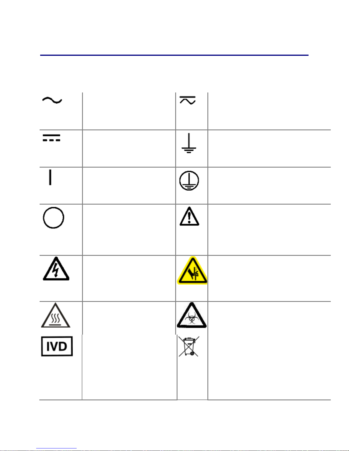
Safety Symbols
Some of these symbols appear on the instrument or accessories:
Courant altern a tif
Wechselstrom
Corrientealterna
Correntealternata
Courant continu
Gleichstrom
Corriente continua
Corrente continua
Marche (alimen tation)
Ein (VerbindungmitdemNetz)
Conectado
Chiuso
Arrêt (alimenta tion)
Aus (TrennungvomNetz)
Desconectado
Aperto
(sconnessionedallaretedialimentazi
one)
Attention, risq ue de choc
électrique
Gefährlicheelektrischeschlag
Precaución, riesgo de
sacudidaeléctrica
Courant continu et courant alternatif
Gleich - und Wechselstrom
Corriente continua y corrientealterna
Bo, height,rne de terre
Erde (Betriebserde)
Borne de tierra
Borne de terre de protection
Schutzleiteranschluss
Borne de tierra de protección
documents)
Attention (voir documents
d’accompanement)
AchtungsieheBegleitpapiere
Atención (vease los documentosincluidos)
Attention, risqued’écra s ement et pincement
Warnen, Gefahr des Zerquetsc hens und
Klemmen
Precaución, riesgo del machacamiento y
sejeción
Attention, surface chaude
Warnen, heißeOberfläche
Precaución, superficiecaliente
Dispositif médic a l d e diagnostic in
vitro
Medizinisches In-VitroDiagnostikum
Dispositivo médico de diagnóstico
in vitro
Dispositivo medico diagnostico in
50™ TS Washer
vitro
Attention, risq uesbiologiquespotentiels
Warnung! MoeglichebiologischeGiftstoffe
Atención, riesgos biológicos
electronic equipment
Les équipements électriques et électroniques
font l’objet d’u ne collecte sélectiv e
Getrennte Sammlung von Elektro- und
Elektronikgeräten
Recogida selectiva de aparatos eléctricos y
electrónicos
Raccolta separata delle apparecchiature
Page 11

| xi
Consult instructions for use
Consultare le istruzioni per uso
Consulter la notic e d ’emploi
Gebrauchsanweisung beachten
Consultar las instrucciones de uso
BioTek Instruments, Inc.
Page 12

Section 2
Installation
This section provides detailed installation instructions.
Unpack and Inspect the Instrument ................................................... 2
Setting Up the 50 TS .......................................................................... 3
Connect the Fluid Supply and Waste System ...................................... 4
Install the Microplate Carrier ........................................................... 13
Attach the Mis t Shield ...................................................................... 15
Page 13

2 |
Unpack and Inspect the Instrument
Important: Save all packaging materials. If the washer is shipped to the
factory for repair or replacement, it must be carefully repackaged in the original
packing materials. Using other forms of commercially available packing
materials, or failure to follow the repackaging instructions may void your
warranty. Improper packaging that results in damage to the instrument may
lead to additional charges
Inspect the shipping box, packaging, instrument, and accessories for signs of
damage.
If the washer is damaged: Notify the carrier and your BioTek representative.
Keep the shipping cartons and packing material for the carrier's inspection.
BioTek will arrange for immediate repair or replacement of your instrument.
Unpack the accessories and the washer. Washers are shipped with two or three
2-liter supply bottles and one 2-liter waste bottle. The 50 TS with Buffer
Switching (“V” version) includes three supply bottles.
Liquid Level Alert™
If you purchased the Liquid Level Alert system, its components are shipped in
a separate box.
• For washers with Buffer Switching (“V” version washers), PN 4070036 includes
a select box, three 2-liter supply bottles, and one 2-liter waste bottle.
• For washers without Buffer Switching, PN 4070035 includes a select box, one 2-
liter supply bottle, and one 2-liter waste bottle.
50™ TS Washer
Page 14

Setting Up the 50 TS
Important: Avoid excessive humidity. Condensation directly on the sensitive
electronic circuits can cause the instrument to fail internal self checks.
Important: The manifold dispense tubes have a protective Teflon collar at the
tip. This is to prevent dripping. Do not remove these coverings!
Operating Environment
The 50 TS washer is sensitive to extreme environmental conditions. For
optimal operation, install the washer:
• on a stable, level surface,
| 3
• in an area where ambient temperatures between 15° - 40°C (59° - 104°F)
can be maintained, and
• away from excess humidity.
BioTek Instruments, Inc.
Page 15
4 |
points towards the manifold.
Connect the Fluid Supply and Waste System
Caution. The washer manifold, the vacuum port, and the supply
bottles have Luer fittings. Finger-tighten only!!
Place the supply and waste bottles on the same horizontal plane as the
washer. This ensures optimum pump performance.
Liquid Level Alert System: If you purchased the optional level alert
accessory, use the special supply and waste bottles provided with the
kit during this installation procedure. Unlike the standard bottles, the
liquid level alert bottles have a sensing device inside, connected to an
electrical cable in the top. When the washer is installed, follow the
instructions to enable the system, See Install the Liq uid Level Alert
System (Optional) on page 9.
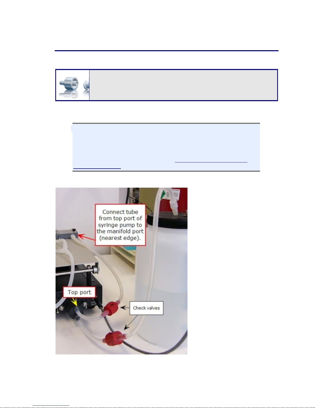
Connect the Fluid Supply
Fluid Supply without Buffer
Switching is shown in this photo.
The tubing connects directly from
the bottle to the syringe pump to
the wash manifold.
1. Locate the tubing with the
check valves used for the
fluid supply, PN: 4070510.
2. Connect the short tube to
the top port of the syringe
pump and to the port on the
wash manifold nearest the
edge. Make sure the flow
arrow on the check valve
50™ TS Washer
Page 16
| 5
3. Connect the cut end of the short tube to the top port of the syringe
pump. Connect the Luer fitting end to the port on the wash manifold
closest to the edge. Make sure the flow arrow on the check valve points
towards the manifold.
4. Connect the long tube to the bottom port of the syringe pump. This is the
fluid supply "Input." Make sure the flow arrow points toward the washer.
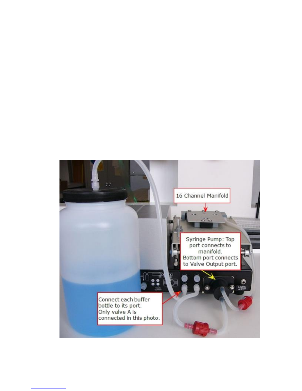
5. Without Buffer Switching: Connect the long tube to the top of the supply
bottle.
With Buffer Switching: The tube will extend only from the syringe pump
to the Valve Output port next to the pump.
1. First, remove the Luer fitting on one end of the tube and cut the long
tube to about 5” (12.7 cm) from the check valve.
2. Reinsert the Luer fitting and connect it to the Valve Output port on the
back of the washer.
Fluid supply with Buffer Switching: tubing connects to internal valves
BioTek Instruments, Inc.
Page 17

6 |
5. Connect the three supply bottles, A, B, C, to their respective ports.
50™ TS Washer
Page 18
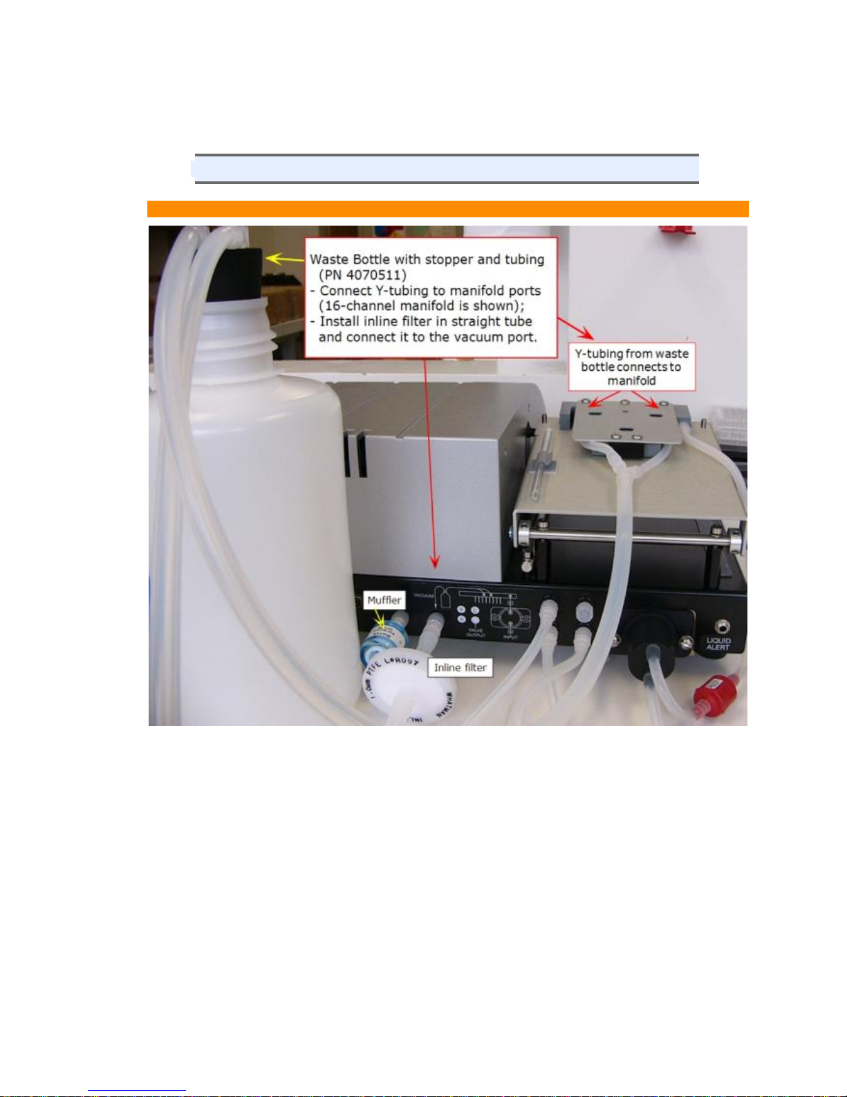
Connect the Waste System
Finger-tighten only all fittings!
All 50 TS models except 8MF, 8M, 8F:
| 7
Connecting the Waste system tubing on the back of the washer
1. Remove the waste bottle cover and replace it with the stopper from the
waste tubing set.
2. Attach the Y-shaped tubing from the waste bottle stopper to the two waste
ports on the back of the wash manifold.
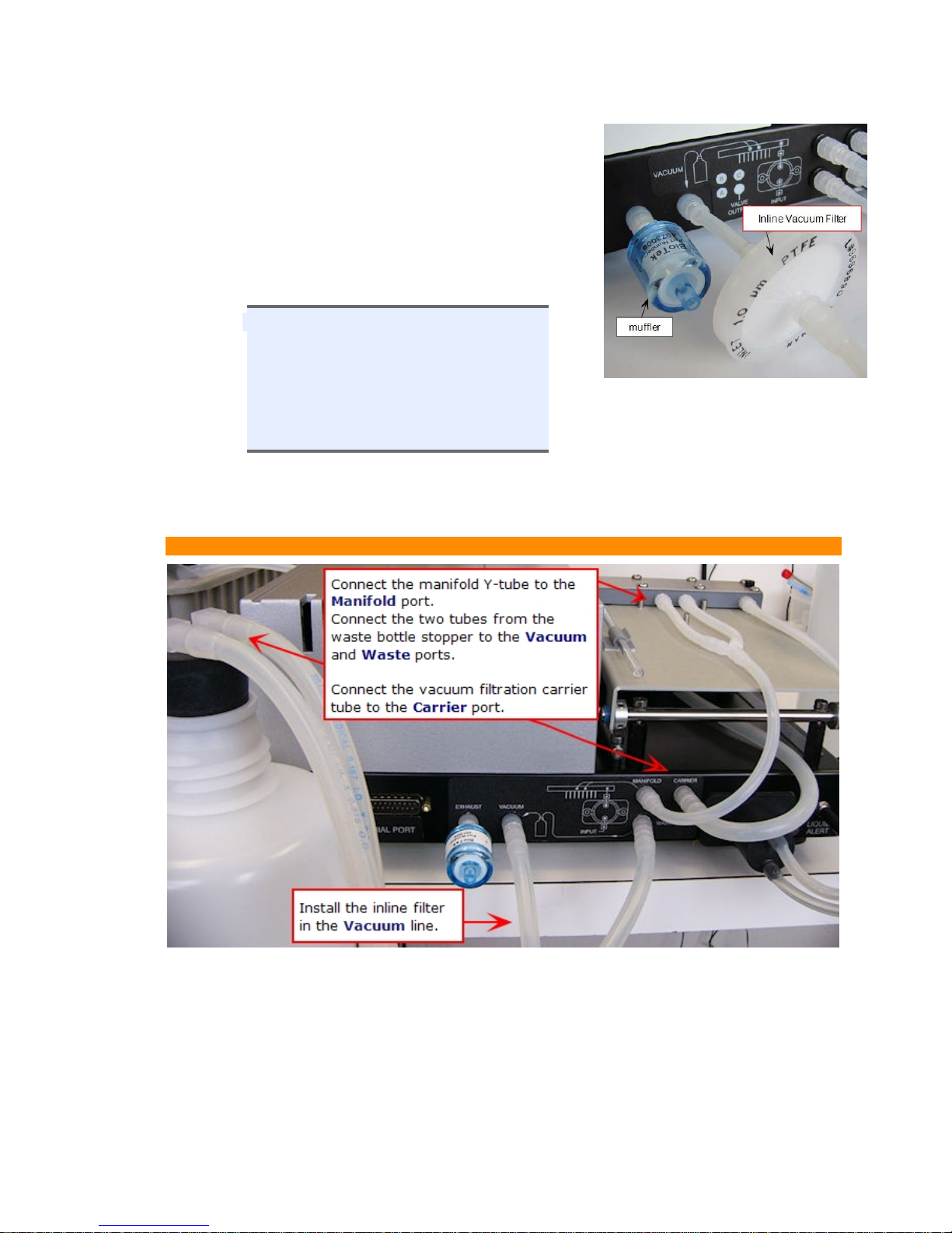
3. Install the inline vacuum filter:
BioTek Instruments, Inc.
Page 19
8 |
1. Cut the tubing that will connect the
about an inch of tubing extending from
Insert the vacuum filter between the cut
waste bottle to the Vacuum port: leave
the Luer fitting that will connect with
the washer.
2.
ends of the tubing.
The inline vacuum filter (PN: 48146)
is optional but strongly
recommended to (1) prevent waste
material aerosols from escaping into
the air, and (2) to serve as a
temporary fluid barrier if the waste
bottle is allowed to overfill.
4. (After inserting the inline vacuum filter) Connect the tubing from the waste
bottle to the Vacuum port on the back of the washer.
50 TS/8F, 8M, 8MF models (for vacuum filtration)
Installing the W aste system for vacuum filtration models: 8F, 8M, and 8MF models.
1. Attach the Y-shaped tubing to the two waste ports on the back of the wash
manifold (two center ports).
2. Connect the end of the Y-waste tubing to the Manifold port on the back of
the washer.
50™ TS Washer
Page 20
| 9
3. Remove the waste bottle cover and replace it with the stopper from the
waste tubing set. Take note of the distinct fittings at the end of each tube:
one connects to the Vacuum port, the other to the Waste port on the back
of the washer.
4. To install the optional inline vacuum filter:
1. Cut the tubing that will connect the waste bottle to the Vacuum port
leaving about an inch of tubing extending from the washer,
2. Insert the vacuum filter between the cut ends of the tubing.
5. Attach the tubing from the waste bottle to their respective ports on the back
of the washer:
• Vacuum port to connect the vacuum pump to the waste bottle,
• Waste port to capture waste fluid from the washer.
6. Connect the tubing from the vacuum filtration carrier to the Carrier port on
the back of the washer.
Disconnect the waste tube from the Carrier port when you are not
using the vacuum filtration carrier. An internal valve preserves the
vacuum required to perform standard aspiration.
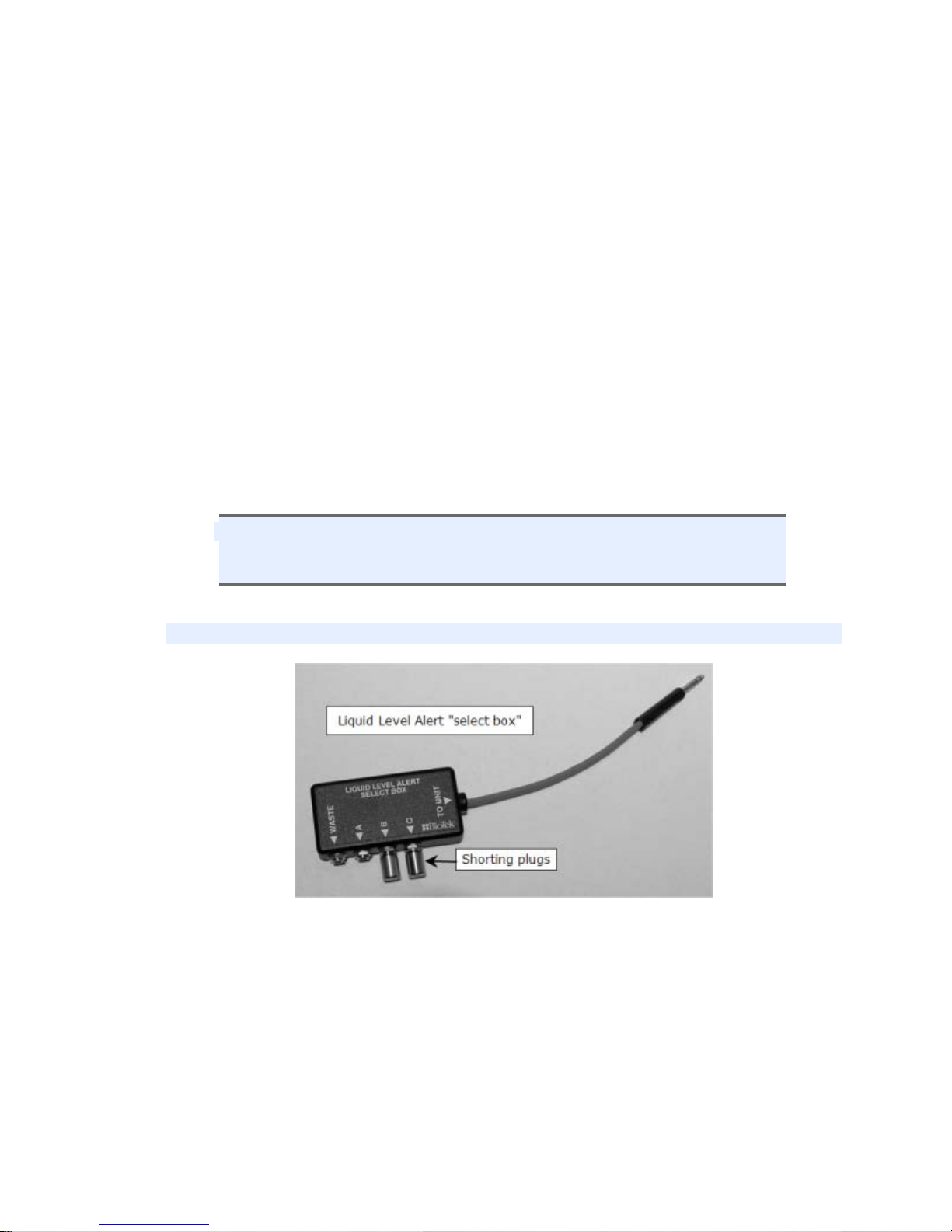
Install the Liquid Level Alert System (Optional)
The Liquid Level Alert select box has ports, labeled A, B, and C, for the
supply bottles, and Waste.
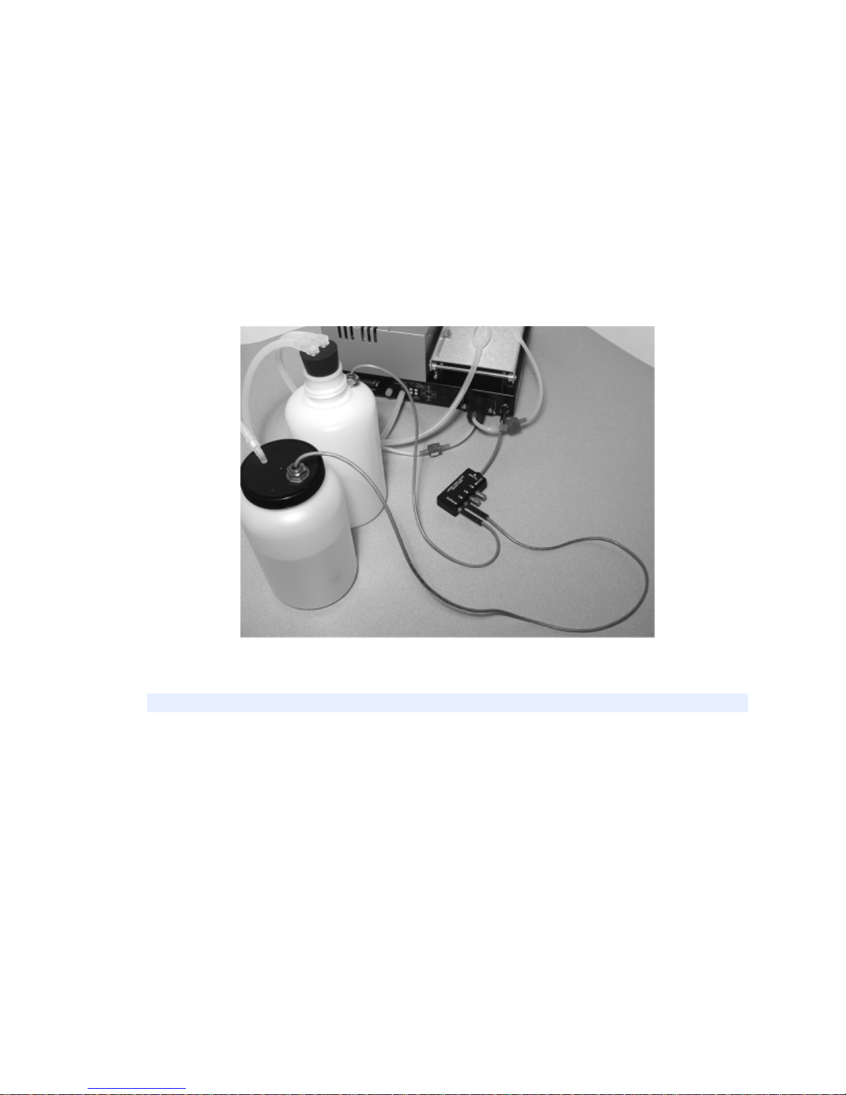
1. If you have not already done so, connect the waste and fluid supply
bottles as described on the previous pages.
2. Connect the cables from the supply and waste bottles to the select box:
BioTek Instruments, Inc.
Page 21
10 |
o For washers with Buffer Switching, connect the supply bottle cables to
the appropriate ports in the select box. If a port is left empty, insert one
of the supplied “shorting plugs” (all ports must be filled).
o For washers without Buffer Switching, connect the s upply bo ttle cable to
port A and then insert the shorting plugs into ports B and C.
o For all washers, connect the waste bottle cable to the WASTE port.
3. Connect the select box to the LIQUID ALERT port on the back of the
washer.
4. Enable Liquid Level Alert by selecting: Instrument>Options and making
Liquid Level Alert Enabled.
Liquid Level Alert Setup
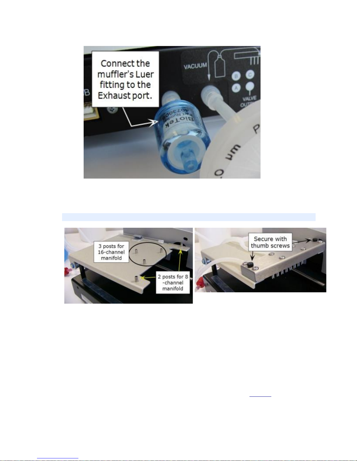
Install Vacuum Pump Muffler (Optional)
Install the optional vacuum pump muffler (PN 4073009) to reduce noise
during operation.
50™ TS Washer
Page 22
| 11
Connect the muffler's Luer fitting on to the Exhaust port (in between the
USB and vacuum ports) on the back of the washer.
Install the 8-, 8s-, 12-, 2x8, or 4 Well Manifold
To install any ma nifold except the 8,16 Well manif old: rest it on the two ou ter posts and
secure with thumbscrews
1. Orient the manifold with the aspirate and dispense tubes facing down,
and the fittings for the supply and waste tubing facing the back of the
washer.
2. Place the manifold gently onto the two support pins on the manifold
mounting bracket closest to the front of the washer.
3. Insert the thumbscrews (2). Do not overtighten.
See also Connect the Fluid Supply and Waste System page 4 for
descriptions of the manifold tubing connections.
BioTek Instruments, Inc.
Page 23
12 |
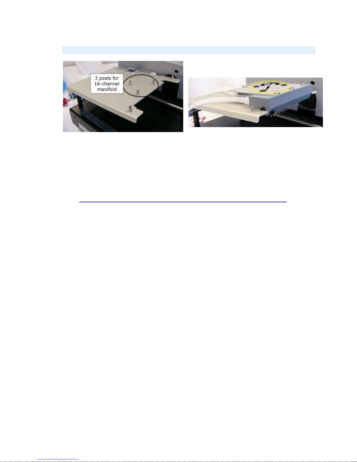
Install the 8,16-Well Manifold
Secure the 16 Well manifold on the 3 posts
with the 3 thumb screws.
1. Orient the manifold with the aspirate and dispense tubes facing down,
and the fittings for the supply and waste tubing facing the back of the
washer.
2. Place the manifold gently onto the three support pins on the manifold
mounting bracket.
3. Insert the thumbscrews (3). Do not overtighten.
See also Connect the Fluid Supply and Waste System on page 4 for
descriptions of the manifold tubing connections.
50™ TS Washer
Page 24
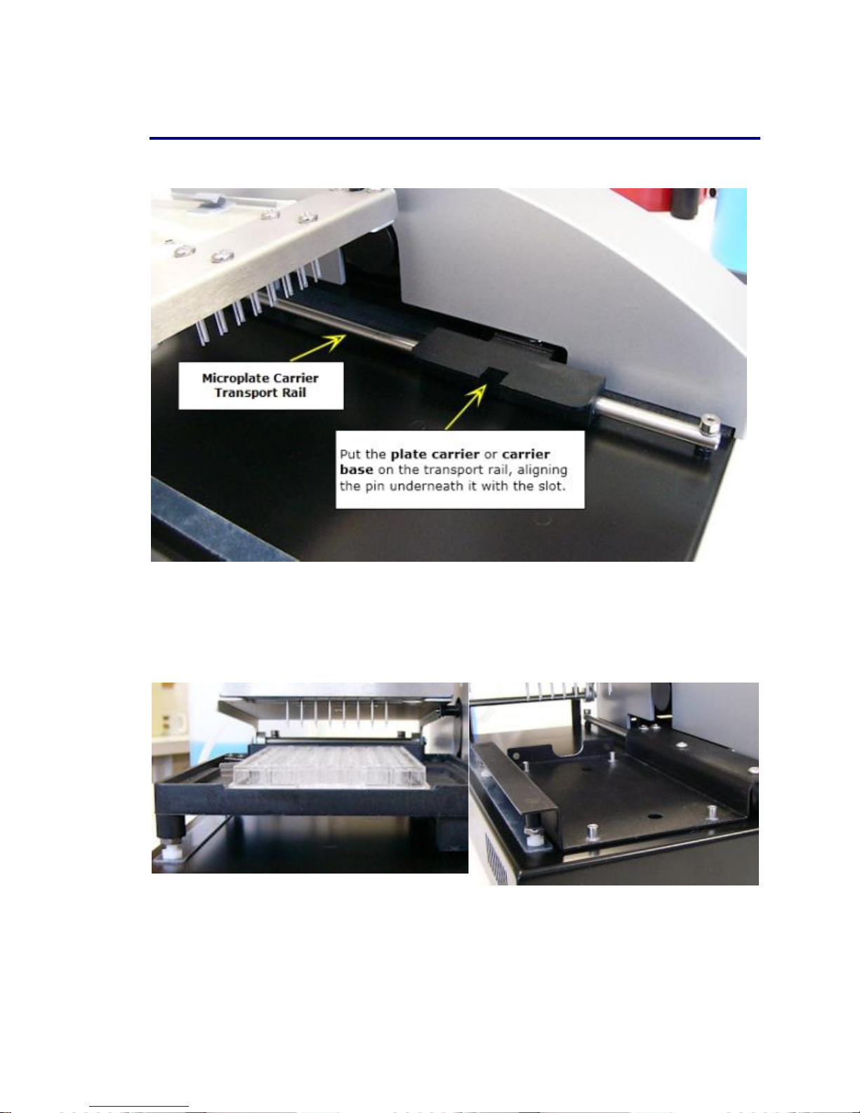
Install the Microplate Carrier
| 13
1. Position the microplate carrier or the carrier base of “F” and “M”
models so the priming trough is closest to the rear of the washer.
2. Line up the pin on the underside of the carrier with the slot on the
carrier transport rail and install the carrier. Rail guides under the carrier
sit on rail.
Standard microplate carrier with p la te . Carrier base for biomagnetic separation and
vacuum filtration plate carriers.
BioTek Instruments, Inc.
Page 25

14 |
Vacuum Filtration and Biomagnetic Separation Carrier
The 50 TS: “F” or “M” models ship with one or two microplate carriers
which fit into the microplate carrier base.
Vacuum filtration plate carrier Biomagnetic separation plate carrier
1. Install the microplate carrier base as described above; except 8F models:
the vacuum filtration carrier is already attached to the carrier base.
2. Observe on the underside of the vacuum filtration and biomagnetic
separation carriers the holes for pins in each of the four corners. Align
the carrier to fit on top of the pins in the carrier base.
3. Vacuum filtration carrier: connect the tubing on the special plate carrier
to the Carrier port on the back of the washer.
• The biomagnetic-separation carrier's priming trough is removable. Make
sure the trough is installed before operation.
Biomagnetic plate carrier with separate priming trough
For vacuum filtration and biomagnetic se paration ass ays, insta ll
the 8- or 8s Well manifold.
50™ TS Washer
Page 26

Disconnect the waste tube from the Carrier port when you are not
using the vacuum filtration carrier. An internal valve preserves the
vacuum required to perform standard aspiration.
Installation Final Check
1. Verify that the tubing was not crimped during installation.
2. Make sure the fluid supply and the waste output tubes are attached to
the appropriate manifold ports. Lift the manifold mounting bracket up
or back to make sure the tubing to the manifold is not being pulled too
tightly.
3. Vacuum Filtration models: make sure there is sufficient room behind
the washer for the waste tubing attached to the special carrier to move
during operation.
| 15
Attach the Mist Shield
The mist shield is also called the aerosol cover.
BioTek Instruments, Inc.
Page 27
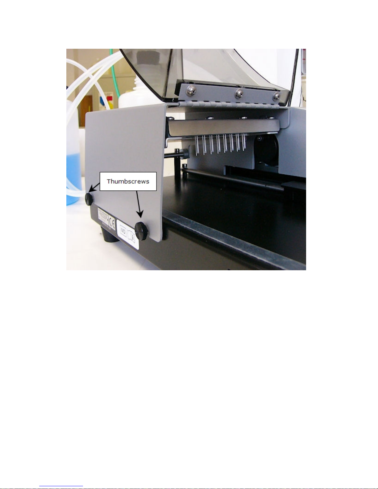
16 |
Mist Shield: open
1. Insert the two thumbscrews into the slots on the washer’s left side. Do
not tighten completely.
2. With the door toward the front of the washer, slide the mist shield
down onto the thumbscrew shafts while inserting the two pins into the
slots on the top left side.
3. Tighten the thumbscrews.
50™ TS Washer
Page 28
Mist Shield: clos ed
| 17
Connecting t he Power Supp ly and Cord
Warning! Po w er Rating. The 50 TS power supply must be
connected to a power receptacle that provides voltage and
current within the specified rating for the system. Use of an
incompatible power receptacle may produce electrical shock
and fire hazards.
Warning! E lec t r ical Grounding. Never use a two-prong plug
adapter to connect primary power to the 50 TS power supply.
The 50 TS Washer uses an external 24-volt power supply. The power
supply automatically adjusts for input voltage in the range of 100 - 250 V~.
1. Plug the power supply’s plug into the washer’s rear panel.
2. Insert the power cord into the power supply and into an appropriate
Use of a two-prong adapter disconnects the utility gro und,
creating a severe shock hazard. Always connect the power cord
directly to a three-prong receptacle with a functional ground.
wall outlet.
Verify Performance
Before using the 50 TS washer for the first time, verify that it is operating
properly by turning the washer on. Turning on the washer initiates a system
BioTek Instruments, Inc.
Page 29

18 |
Self-Test to check the manifold, microplate carrier, vacuum pump and syringe
pump positioning and operation.
When the self test has completed successfully, the washer is ready for use.
If the test passes, the Main Menu is displayed.
If the test fails, the washer beeps repeatedly and displays an error code. If
this happens, note the error code and then press Stop on the keypad to stop
the beeping. Look up Error Codes on page 1 to determine its cause. If the
problem is something you can fix, turn off the washer, fix the problem, and
then turn the washer back on. Otherwise, contact BioTek’s Technical
Assistance Center.
The Instrument Testing section provides recommended procedures to
perform after the instrument is installed and set up as described in this
chapter, and before the instrument is used in a laboratory environment.
The successful completion of the Installation Qualification confirms that the
washer and its components have been supplied as ordered and ensures that
they are assembled and configured properly for your lab environment. The
successful completion of the Operational Qualification confirms that the
washer is operating according to specification.
Note: An instrument qualification package (PN 155) for the 50 TS
is available for purchase from BioTek. The pac kage contains thorough
procedures for per forming Installation Qualif ication, Operational
Qualification and Performance Qualification (IQ/OQ/PQ) and
preventive maintenance (PM). Extensive Checklists and Logbooks are
included for recording results. Contact your local dealer for more
information.
Important! Review Optimize Performance recommendations in the
operator's manual, which describes necessary steps to perform before
running the washer.
50™ TS Washer
Page 30

Section 3
Getting Started
This section introduces the basics of operating the 50 TS. For
more detailed and comprehensive instructions, please refer
to the operator's manual.
AutoPrime .......................................................................................... 2
Wash a Plate ...................................................................................... 4
Optimize Performance ........................................................................ 7
Run a Predefined Protocol .................................................................. 8
Create a Protocol .............................................................................. 13
Instrument Configuration - Setup Cont rols ...................................... 23
Page 31

2 |
smaller amount of fluid
Quick Prime
Select Quick>Prime.
BioTek defines two types of prime:
• Manifold: uses a
to condition the
dispense tips.
Press the “Priming
” button to run a
for
manifold prime
immediately before a
wash or dispense step
to correct for
evaporation between
runs.
• System: priming is necessary when changing fluids, and at the start a nd end of
the day to flush the tubing. Except b uffer switching models should run the
System option when the instrument has been idle be t ween runs.
Best practice: for the most precise dispense volumes, always run a "Quick
Manifold Prime" before a basic wash or dispense. Buffer Switching models may
require a “System” prime if the instrument has been idle.
AutoPrime
LHC: Tools>Instrument Utilities> AutoPrime
From the Home screen: Instrument>AutoPrime
Recommended for optimum performance, AutoPrime keeps the tubing wet in
between runs and can be an essential part of your daily maintenance routine.
About AutoPr ime
AutoPrime automatically primes the tubing whenever the instrument is idle
for a specified time. Keeping the tubes wet prevents clogging and mitigates
fluid evaporation at the tips. AutoPrime's submerge feature lets you soak the
tubes for extended periods, which is an effective maintenance option.
50™ TS Washer
Page 32

Specify the Interval a nd Auto Prime Parameters
Touchscreen:
LHC:
time interval that
will trigger priming; up to
AutoPrime only runs when the Main Menu (Home) is displayed and the
instrument has been idle for a specified interval.
To set AutoPrime:
| 3
1. Select Instrument at the main menu and
select AutoPrime.
1. Select Tools>Instrument
Utilities> AutoPrime
tab.
2. “Enable” AutoPrime and
specify the parameters:
• the idle-
24 hours.
• Set the Submerge
Duration
• Flow rate, volume, and
buffer valve, if
applicable.
, if desired.
3. LHC users: click Send to
transfer the settings to the
instrument.
BioTek Instruments, Inc.
Page 33

4 |
performance.
: two options for
on daily
to prime
dispense tips to correct
for evaporation.
wash.
Wash a Plate
Two ways to wash a plate:
• Quick Wash: use the
Quick menu to wash
strips or a plate using
default instrument
settings.
• Protocol: run a
predefined wash
protocol: touch your
choice on the Main
Menu. Protocols let
you customize the
wash parameters to
improve assay
Quick Wash
Press Quick at the Main
Menu (Home) to Prime the
tubing and run a Basic
Wash.
• Prime
the most comm
uses: System
all the tubing, when
changing buffers, for
example, and
Manifold to prime the
• Basic Wash: after priming the tubing, specify the volume-per-well, buffer
bottle, if applicable, number of wash cycles and how many strips (or rows) to
When you are ready to wash a plate:
1. Fill the supply bottle and connect it to the washer, (empty the waste bottle,
if necessary).
2. Prime the tubing: use Quick Prime or run a Maintenance protocol.
3. Properly seat the microplate or microstrips holder in the plate carrier with
well A1 closest to the manifold/dispense tips.
50™ TS Washer
Page 34

4. Press .
Wash Protocol
Predefined protocols,
including sample protocols
provided with the 50 TS
reside on the Main Menu.
Touch a protocol to run it.
See Create a Protocolon
page 13.
| 5
If more precise positioning of the aspirate tubes, more or fewer wash cycles, or
a slower aspirate travel rate would improve your results, e.g. reduce residuals,
use the Protocol menu to customize a protocol for your assays. Several sample
protocols are provided, which can be used as templates to give you shortcut to
creating your own protocols. "Copy" a sample protocol to preserve the
original, and start the customization with optimized parameters for the plate
type.
BioTek Instruments, Inc.
Page 35

6 |
About Wash Protocols
Minimally, a wash protocol has one wash cycle, which is an aspirate step
followed by a dispense step. By default, the 50 TS’s wash protocol has three
wash cycles followed by a Final Aspirate step. You can customize the wash
protocol:
o Change the number of cycles,
o Add pre-wash steps like bottom wash , fo r ve ry vi g orous w ash ing,
o Remove the final aspirate step and raise the aspirate height to increase
residu als in t he wells,
o Shake the plate to mix the contents,
o Add a Soak or delay to incubate the contents at room temperature,
o Etc.
See Run a Predefined Protocol on page 8.
See Create a Protocol on page 13.
50™ TS Washer
Page 36

| 7
Optimize Performance
Important: Always fully prime the washer before running a wash or dispense program. Do
not rely on AutoPrime to pre-prime the tubing for a protocol. AutoPrime is designed for
maintenance purposes to keep the tubing in a wetted state between runs. Enable "Prime before
Washing" when creating a protocol and when using the Quick menu, prime the tubing before
running a basic wash.
Always prime the washer with dispense fluid before a run and when finished with the
washer. Flush the tubing by running a prime or maintenance program. Find
guidelines in the Mainte n ance chapter.
Vacuum Inline Filter: Installing the hydrophobic inline vacuum filter before using
the 50 TS is strongly recommended.
Before Running the Washer
• Fill the wash/rinse bottles with sufficient fluid. Make sure the supply tube is in
the liquid.
• Empty the waste bottle and firmly seat the waste bottle’ s s topper. To prevent
fluid from backing up into the vacuum pump, never allow the waste bottle to
become more than three-quarters full. Alternatively, install the Liquid Level
Alert.
• Check the external tubing connections for kinks and clogs.
• Make sure the bottles, solutions, and tub i ng are clean and do not contain any
particles or mold.
• To avoid creating air bubbles every time the supply bottle is filled, make a mark
halfway down the bottle a nd refill when the fluid level dro p s to that point.
Unscrew the cap and let it hang over the side just enough to avoid emptying the
inside tube and enough to refill the bottle.
• Enable AutoPrime to keep the tubing wet during idle periods.
• Always use the correct microplate/microstrip types for the manifold:
• 8, 8s, and 2x8 Well manifold: 96-well plates, 8-well strips.
• 12 Well manifold: 96-well plates, 12-well strips.
• 8,16 Well manifold: 96- or 384-well plates, 8-well strips.
• 4 Well manifold: 24-well plates.
• Vacuum filtration is performed only on ful l plates. Microstrips are no t
supported.
• Always put microstrips in the holder before loading them onto the carrier.
• Position microplates or strip holders with well A1 closest to the rear of the
washer.
• Vacuum filtration models: make sure there is sufficient flex room for the tubing
connected to the vacuum filtration carrier during operation.
BioTek Instruments, Inc.
Page 37

8 |
Keep the Washer and Supplies Clean
Perform daily, overnight, and periodic maintenance as described in the
Maintenance Chapter including:
• Cleaning the manifold tube s and chambers.
• Cleaning the plate carrier.
• Cleaning the supply, rinse, and waste bottles.
• Rinsing and checking the tubing.
Protocol Parameters and Instrument Settings
• Be sure to enter the correct ‘First Strip’ and ‘Number of Strips’ values at run-
time.
• Washers with Buffer Switching (“V” version washers): Specify the correct
reagent bottle (A, B, or C).
• Make sure the Dispense (overflow) Height (Z-axis position) in the wash protocol
is low enough to remove (aspirate) excess fluid during the dispense step.
• If you use more than one manifold, make sure the instrument’s setting matches
the installed manifold and plate carrier.
Run a Predefined Protocol
BioTek ships the 50 TS with several predefined protocols onboard. See
Predefined Onboard Protocols Listing
on page 9.
Certain prompts are displayed when a protocol is selected for run. Obey the
prompts by making selections and completing required tasks.
Two options:
1. At the Main Menu, touch the protocol you want to run, or navigate to the
desired protocol using the Next and Prev(previous) buttons.
2. Select Maintenance at the Main Menu to run a maintenance or instrument
qualification (QC) protocol.
Running a Protocol
When you run a protocol on the 50 TS the following prompt may appear,
depending on the type of protocol.
50™ TS Washer
Page 38

Options Actions
Protocol Name
COSTAR_FLAT
COSTAR_ROUND
NUNC_FLAT
NUNC_ROUND
Plate Type
96
96
96
96
Number of Cycles
3 3 3
3
Wash Format
Plate
Plate
Plate
Plate
Soak After Dispense
No
No
No
No
Shake After Soak
No
No
No
No
Prime After Soak
No
No
No
No
Dispense Volume
300
300
300
300
Dispense Flow Rate
5 5 5
5
Dispense Height: Z
Offset
116
116
116
116
Dispense Position: Y
Offset
0 0 0
0
Bottom Wash First
No
No
No
No
Prime Before Start
Yes
Yes
Yes
Yes
Prime Volume
5 5 5 5 Prime Flow Rate
5 5 5
5
First Strip Specify the number of the first strip to be washed.
| 9
Number of
Strips
Specify the number of microwell strips (microplate rows or
columns) to be processed:
• 1 to 12 for the 8- or 8s Well manifold
• 1 to 8 for the 12 Well manifold
• 1 to 24 for the 8,16 Well manifold
• 1 to 6 for the 4 Well manifold
• An even number between 1 to 12 for the 2x8 Well manifold
Predefined Onboard Protocols Listing
BioTek installs these predefined protocols onboard compatible 50 TS
models. Run predefined protocols from the Main Menu (Home). Protocol
settings have been optimized based on experience in our applications lab.
Sample Wash Protocols for all 50 TS Models with 8, 8s, and 12 Well
Manifolds:
BioTek Instruments, Inc.
Page 39

10 |
Protocol Name
COSTAR_FLAT
COSTAR_ROUND
NUNC_FLAT
NUNC_ROUND
Aspirate Height: Z
Offset
28
30
25
33
Aspirate Positi on: Y
Offset
-20
12
-20
12
Aspirate Rate
5 5 5
5
Aspirate Delay
0 0 0 0 Crosswise Aspir a tion
No
No
No
No
Final Aspirate
Yes
Yes
Yes
Yes
Final Aspirate Delay
0 0 0
0
Protocol Name
COSTAR_
FLT16_96
COSTAR_
FLT16_384
NUNC_
FLT16_96
NUNC_
FLT16_384
Plate Type
96
384
96
384
Number of Cycles
3 3 3
3
Wash Format
Plate
Plate
Plate
Plate
Soak After Dispense
No
No
No
No
Shake After Soak
No
No
No
No
Prime After Soak
No
No
No
No
Dispense Volume
300
100
300
100
Dispense Flow Rate
5 5 5
5
Dispense Height
120
120
120
120
Horizontal Dispe nse
Position
0 0 0
0
Bottom Wash First
No
No
No
No
Prime Before Start
Yes
Yes
Yes
Yes
Prime Volume
5 5 5
5
Prime Flow Rate
5 5 5
5
Aspirate Height
26
22
26
22
Horizontal Aspirate
Position
0 0 0
0
Aspirate Rate
5 5 5 5 Aspirate Delay
0 0 0 0 Crosswise Aspir a tion
No
No
No
No
Sample Wash Protocols for all 50 TS Models with 8,16 Well Manifolds:
50™ TS Washer
Page 40

Protocol Name
COSTAR_
FLT16_96
COSTAR_
FLT16_384
NUNC_
FLT16_96
NUNC_
FLT16_384
Final Aspirate
Yes
Yes
Yes
Yes
Final Aspirate Delay
0 0 0
0
Biometric Separation Sample Protocols for 50TS: 8M, 8MV, 8MF Models
Protocol Name
LUM_MAG_FLAT_96
LUM_MAG_RND_96
Plate Type
96
96 Shake 1 sec, 1 (15Hz), soak 1 min
Number of Cycles
2 2 Wash Format
Plate
Plate
Soak After Dispense
Yes, 30 sec
Yes, 30 sec
Shake After Soak
No
No
Prime After Soak
No
No
Dispense Volume
200
100
Dispense Flow Rate
3
5
Dispense Height
120
128
Horizontal Dispe nse Position
0
0
Bottom Wash First
No
No
Prime Before Start
Yes
Yes
Prime Volume
5
5
Prime Flow Rate
5
5
Aspirate Height
29
58
Horizontal Aspirate Position
0
24
Aspirate Rate
7 1 Aspirate Delay
0 0 Crosswise Aspir a tion
No
No
Final Aspirate
Yes
Yes
Final Aspirate Heig ht
38
58
Final Horizontal Aspirate Position
0
24
Final Aspirate Rate
7 1 Final Aspirate Delay
0
0
| 11
BioTek Instruments, Inc.
Page 41

12 |
DISPENSE
µL/well
Dispense Height (Z)
Flow Rate
accuracy_qc_test
300
146
5
accur_qc_test384
100
120
6
ASPIRATE
Height (Z)
Asp Horizontal (Y)
Travel Rate
residual_qc_test
28
-20
1
resid_qc_test384
22 0 3
Vacuum Filtration
Volume: µL/well
Flow Rate
VAC30
300
6
MAINTENANCE
DAY_RINSE
DECONTAMINATION
LONG_SHUTDOWN
OVERNIGHT_LOOP
RINSE_AND_SOAK
PRIME_ALL_BUFFERS1
Qualification Protocols
Select the Maintenance menu on the Home screen.
Maintenance Protocols
1
For "V" models with buffer switching capability.
50™ TS Washer
Page 42

Create a Protocol
Enter a unique name for the
Follow these general guidelines for creating a protocol. See Protocol Parameters
Reference Tables on page 15.
1. Select Protocol at the main
menu.
2. Select Create.
3.
new protocol.
4. Select the Plate Type and
press Save.
| 13
5. Press Add and select the
type of action to perform.
6. Define the parameters for
the step and add more
steps, as needed.
BioTek Instruments, Inc.
Page 43

14 |
Select a step and then use the
, and
Cut
reposition steps. To paste a step, select the step
or <end of steps>
the copied or cut step, then press Paste.
to enable and
to better
To fine-tune a
protocol to improve assay
performance, select the protocol
and press Edit at the Protocol
Definition screen. Then, select the
step and press Edit to modify its
parameters.
Press Info to change the
protocol’s name or plate type.
Save time by
copying a similar protocol and
editing its steps.
Wash Step
Touch the
Aspirate and/or
Dispense boxes to modify the
default parameters for these parts
of the wash step.
Press Wash options
define additional actions.
Toggle the Yes/No buttons to
enable or disable an option.
Press Edit to define the
parameters of the option.
See Wash Protocol Parameterson
page 16 for descriptions.
Copy, Paste
buttons as needed to add, remove or
below the desired position of
In an aspirate or dispense step,
press Advanced options
position the manifold tubes in the
Z-axis (height) and Y-axis
(horizontal position). Some
experimentation may be needed to
find optimal settings.
50™ TS Washer
Best practice: In a wash step, set a
dispense height that positions the aspirate
tubes at the top of wells to draw off any
overflow.
Page 44

Protocol Parameters Reference Tables
Review these tables for details about the available protocol parameters:
o Wash Protocol Parameters on page 16
| 15
o Dispense Protocol Parameters
o Aspiration Protocol Parameters
o Soak and Shake Protocol Parameters
on page 17
Define: Wash Parameter Categories
When creating or editing a wash protocol, parameters are organized by
the following categories:
Step Parameters
METHOD
DISP
ASPIR
Wash cycles, plate or strip format, soaking and shaking, soak duration,
shake before soak, shake duration, shake intensity, prime after soak,
prime volume and prime flow rate.
Dispense Volume, Dispense Flow Rate, Dispense Height, Ho rizontal
Dispense Position, Bottom bv Wash First, Bottom Dispense Volume,
Bottom Flow Rate, Bottom Dispense Height, Bottom Horizontal Position,
Prime Before Start, Prime Volume, Prime Flow Rate.
Aspirate Height, Horizontal Aspirate Position, Aspirate Rate, Aspirate
Delay, Crosswise Aspirate, Crosswise On, Crosswise Height, Crosswise
Horizontal Position, Final Aspiration, Final Aspirate Delay.
on page 19
on page 20
BioTek Instruments, Inc.
Page 45

16 |
(except 1-7 for the 12-channel manifold, and 1-5 for the 4-,
Wash Protocol Parameters
Method Action/Description Default
Number of
Cycles
Wash
Format:
Plate or
Strip.
Soak/
Shake
Soak
Duration
One wash cycle includes, at minimum, one aspirate a nd
dispense sequence. Other options added to the protocol, like
shake and soak, are also performed in each cycle. Pre-prime,
when selected, is performed one time before the wash cycles.
Bottom Wash adds another cycle to the protocol when
enabled. Final Aspirate is done once after all cycles are
completed.
Plate format performs each cycle on the entire plate (or all of
the strips) before it starts the next cycle. Strip format
performs all cycles on one strip before it moves to the next
strip. You must specify the number of strips to wash at
runtime.
Enable soaking and/or shaking to steep and/or mix the wash
buffer in the wells after the dispense step; then specify a
duration.
The amount of time to delay processing or to steep fluid in the
wells before aspiration.
A soak begins after the wash buffer is dispensed. In some
assays it enhances washing by allowing unbound material to
diffuse into the wash buffer. When washing strips in a plate
format use a soak that lasts as long as it takes to process one
wash cycle of all strips.
3
Plate
No
30
Shake
Duration
Shake
Intensity
The amount of time to agitate the plate. The duration range is
from1 second to 30 minutes.
Specify the intensity of microwell shaking. The options range
from 1 to 5, where 1 = Least Intense, 5 = Most Intense. The
washer shows the corresponding cycles/sec value for each
option.
Prime
Between
Cycles?
Prime
Volume
Prime Flow
Rate
50™ TS Washer
Choose Yes to prime the dispense tubes between cycles, to
correct for evaporation, for example. Generally, this is only
necessary after a delay or a long soak, >10 minutes.
Specify the volume in milliliters. The range is from 1 to 200
mL.
Specify the rate at which to pump the priming fluid into the
dispense tubes. The flow rate options range from 1 to 9
5
3
No
5
5
Page 46

| 17
and 2x8-well manifolds), w here 1 = Slowest, 9 = Fastest. See
Method Action/Description Default
Dispense and Prime Flow Rates on page 1 .
Dispense Protocol Parameters
Options Actions Default
Dispense Volume The volume to dispense per well per wash cycle. The
volume range is 50 to 3000 µL/well for 96-well pla t e s .
When dispensing to 384-well plates, the range is 253000 μl/well.
Dispense Flow Rate Flow rates range from 1 to 9 (except 1-7 for the 12-
channel manifold, and 1-5 for the 4 and 2x8 Well
manifolds). 1 = Slowest, 9 = Fastest. See Dispense
and Prime Flow Rates on page 1. The flow rate must be
valid for the manifold and dispense volume. For
Troubleshooting: See Dispense Volume Invalid for
Manifold Type (0F00 Error).
Dispense Hei gh t (Zaxis)
The height between the bottom of the aspirate tubes
and the carrier surface when dispensing. The dispense
tubes are shorter than the aspirate tubes.
The Dispense Height range is from 12 to 180 steps.
The washer displays the corresponding millimeters. 12
is closest to the carrier surface, 180 is furthest from
this surface.
Overflow Position: It is considered goo d practice to set
a dispense height that positions the aspirate tubes at
the top of wells to draw off any overflow.
300
5
120
Horizontal Position
(Y-axis)
The position of the manifold tubes in relation to the
center of the microwells.
The Horizontal Disp Pos range is from -24 to 24 for the
8- and 12-channel manifolds and the 2x8 manifold; -88
to 24 for the 8s-manifold; -24 to 15 for the 16-channel
when addressing 96-well plates and -22 to 10 for 384well plates; the 4 (24-well plate) manifold range is 180-60. The washer displays the corresponding
millimeters.
A negative offset moves the dispense tubes back, aw ay
from the front of the washer. A positive offset moves
the dispense tubes toward the front of the washer. A
setting of 0 indicates no offset.
0
BioTek Instruments, Inc.
Page 47

18 |
Options Actions Default
Bottom Wash First?
Bottom washing adds
an initial aspiratedispense sequence to
the specified number
of wash cycles when
extra vigorous
washing is required.
Specify bottom wash parameters to position the
manifold deep in the well. For example, set the Bottom
Disp Height to between 30-50 steps. Reagent is
dispensed and aspirated simultaneously at this height
to create cleaning turbulence. The plate is aspirated
again and the process ends with a final dispense to fill
the wells.
In Vacuum Filtration models, when the aspirate step is
No
defined as VAC, this aspiration method is used for the
Bottom Wash, as wel l.
Bottom Disp Volume The volume range is 50 to 3000 µL/well. 150-400
300
µL/well is typical.
Bottom Flow Rate Valid options: 1 to 9 (except 1-7 for the 12-channel
5
manifold, and 1-5 for t he 4 and 2x8 Well manifolds).
Bottom Disp Height Valid range from 12 to 180 steps. 60
Bottom Horiz Pos Valid range is same as regular wash step (see above). 0
• Negative values: To enter a negative value, toggle the +/- button.
Do not confuse Bottom Wash options with vacuum filtration, which
evacuates filter or membrane plates from below. Bottom wash is for
extra vigorous washing to reduce background or noise when reading
the plate. Review Vacuum Filtration for Filter Plate Assays on page 1.
50™ TS Washer
Page 48

| 19
Aspiration Protocol Parameters
Options Actions Default
Aspirate Type Standard aspiration using the manifold or Vacuum
Filtration for 8F and 8MF models using the vacuum
filtration carrier.
Filtration Time When Aspirate Type is set to Vacuum Filtration. The
range is 1-180 seconds. Experimentation is
recommended to determine the optimal setting for your
assays.
Aspirate Height
(Z-axis)
The height between the bottom of the aspirate tubes and
the carrier surface when aspirating the microwells. The
aspirate tubes are longer than the dispense tubes.
Ranges from 12 to 180 steps. The washer shows the
corresponding millimeters. 12 is the closest to the carrier,
180 is the furthest.
Horizontal Position
(Y-axis)
The position of the manifold tubes in relation to the
center of the microwells.
The Y-axis range is from -24 to 24 for the 8- and 12channel manifolds and the 2x8 ma nifold; -88 to 24 for
the 8s-manifold; -24 to 15 for the 16-channel when
addressing 96-well plates and -22 to 10 for 384-well
plates; the 4 (24-well plate) manifo ld range is -180-60.
The washer displays the corresponding millimeters.
A negative offset moves the aspirate tubes back, away
from the front of the washer. A positive offset moves the
tubes toward the front of the washer. A setting of 0
indicates no offset.
Note: For flat-bottom plates, position the aspirate tubes
near the edge of the well for minimal residual volume.
30
24
0
Travel Rate The rate at which the wash manifold travels down into
Aspirate Delay The time delay starting when the tube is at its aspiration
3
the wells. Options range from 1 to 7, where 1 is slowest
and 7 is fastest. The washer shows the corresponding
mm/sec value for each option.
0
height and ending when it nex t moves. The valid range is
0 to 5000 milliseconds.
The delay applies to the normal (initial) aspiration when
Secondary (aka Crosswise) Aspirate is disabled. If
Secondary Aspiration is enabled, the delay applies to the
second, not t he initial, aspiration.
BioTek Instruments, Inc.
Page 49

20 |
Options Actions Default
Secondary2
aspirate
(Crosswise)
A secondary or crosswise aspiration is a two-step
aspiration. The wells are first aspirated at the horizontal
aspirate position. The aspirate tubes rise a fixed number
of steps and then do a second aspiration at the secondary
position. It is useful for e liminating residual sample o r
reagent from the wall perimeter.
Final Aspirate Select YES to designate a fin al aspiration, leaving the
wells empty.
Final Aspirate
Delay
Same as Aspiration Delay (see above) applied to the final
aspiration.
• Negative values: To enter a negative value, toggle the +/- button.
2
Secondary and Final Aspiration are only available in a wash step, not stand-alone aspiration
steps.
Soak and Shake Protocol Parameters
No
Yes
0
Add a Shake/Soak step to the protocol to mix plate contents.
50™ TS Washer
Page 50

Options Actions
Shake To mix the wells' content during the procedure.
Before shaking begins, the manifold rises and the carrier
returns home so the tubes are above the priming trough
and cannot contaminate the plate/strips.
Shake Duration Defines how long to shake the plate/strips. The duration
range is from 1 second to 30 minutes.
Shake Intensity Specify the shake intensity from 1 to 5, where 1 is least
intense, 5 is most intense. The washer shows the
corresponding cycles/sec or Hertz (Hz) value for each
option.
Soak Duration Soak Duration is the time to allow the wash buffer to
remain in the wells before aspiration. The range is from 1
second to 30 minutes.
Note: When washing strips in a plate format define a soak
that lasts as long as it takes to process one wash cycle of
all strips.
| 21
System Startup
To turn on the 50 TS, press the on/off switch on the right side of the base. The
50 TS performs a self-test each time it is started.
If the self-test fails, the washer will beep and display an error code. Note the
error code and then press OK to stop the beeping. Look up the code in Error
Codes.
Select Instrument>Options to restart the
instrument to clear error messages or to check for errors.
How to copy a protocol
You can save time creating protocols by copying a protocol that shares some of
the same protocol parameters and then editing the copy to meet your needs.
1. Select Protocol at the main menu.
2. Touch the protocol you want to copy, and select Copy.
BioTek Instruments, Inc.
Page 51

22 |
3. Name the new protocol, choose the plate type and press Save.
4. Select Edit to "Add" or “Edit” steps or otherwise change the protocol.
Press Exit when finished.
When editing a protocol, press Info to change the protocol’s name or
plate type.
How to delete a protocol
Delete a protocol to remove it from the Home screen (Main Menu), and to freeup space onboard for more protocols.
1. Select Protocol at the Home screen.
2. Highlight the protocol you want to remove and press Delete.
3. Confirm your intention to remove the protocol at the prompt.
50™ TS Washer
Page 52

Instrument Configuration - Setup Controls
The Instrument menu leads to controls for:
o Instrument Setup below
o AutoPrime
Instrument Setti ngs
Manifold Selection
Your 50 TS was initially configured for and shipped with a wash
manifold. The washer’s manifold setting must match the type of manifold
installed on the instrument. If you change the hardware, you must also
change the setting.
| 23
Manifold Type PN Plate Type Onboard
4 Well 1550504 24-well 4
8 Well 4070512 96-well 8
8 Well Short Dispense
Tube
2 X 8 Well 1550501 96-well 2x8
12 Well 4070513 96-well 12
8, 16 Well 4070527 96 & 384-well 8,16
Plate Carrier Selection
4070519 96-well 8s
The type of plate carrier installed on the instrument must match this setting to
ensure expected performance.
• Standard
384 Well: compatible with the 8,16 Well manifold.
•
Magnetic Separation: special plate carrier for holding a magnet.
•
Vacuum Filtration: special carrier for performing vacuum aspiration or
•
filtration assays. This setting must be selected to run a vacuum filtration
protocol.
BioTek Instruments, Inc.
Page 53

24 |
Plate Clearance Height
Plate Clearance Height specifies how high to raise the manifold tubes to
prevent crashes when the plate carrier moves. The clearance height range is
12 (3.048 mm) to 195 (24.77 mm), with a default value of 146 (18.55 mm).
Use this option with 8M, 8MV and 8MF models to increase the plate
clearance height for magnetic bead assays.
Note: When using the 4 Well Manifold the Plate Clearance setting is ignored and
the manifold is raised to its highest position during travel.
To change the plate clearance height, select: Instrument>Config>Plate
Clearance
Liquid Level Sensor
.
50 TS washers support Liquid Level Alert: with a level sensing device
inside the supply and waste bottles. The sensor is activated when a supply
bottle’s fluid level drops to approximately 400-450 mL and the waste
bottle’s fluid level rises to approximately 1400-1450 mL.
The washer checks the status of the sensor at the start and end of all runs.
Error codes 2800 or 2900 display when a sensor is activated. If this happens,
press OK, check the state of the supply and waste bottles. You can fill or
empty the bottles, as needed, and then continue the run, if desired.
Sensor detection is disabled on the washer by default. To change the setting,
select: Instrument>Options and set Liquid Level Sensing to Enabled.
Protocol Display Order
Select Instrument>Options to change the sort order of the protocols on the
Main Menu.
• Last run first: reorders the list beginning with the protocol that was last run.
Alphabetically: orders this list by protocol name.
•
AutoPrime
AutoPrime keeps the tubing wet to prevent clogging during idle periods. It
is highly recommended for daily and overnight maintenance.
AutoPrime automatically primes the washer when it has been idle for a
user-specified amount of time. AutoPrime is recommended when the
washer is used intermittently throughout the day, to keep the manifold
tubes in a wetted condition between runs. It is especially useful when using
50™ TS Washer
Page 54

| 25
wash buffers that are prone to harden or crystallize. See AutoPrime on page
2.
BioTek Instruments, Inc.
Page 55

Section 4
Maintenance
This section contains recommendations for maintaining the
50 TS. For more detailed and comprehensive instructions,
please refer to the operator's manual.
About Maintaining the Washer ........................................................... 2
Recommended Maintenance Schedule ................................................ 3
Daily Maintenance: Rinse/Soak t he Fluid Path ................................... 8
Clean Components............................................................................ 11
Decontaminate the Washer .............................................................. 18
Page 56

2 |
About Maintaining the Washer
This section describes a set of procedures to perform regularly to maintain
equipment in top condition. For example, during normal operation, salt
crystals may build up and clog the valves and tubes. Adherence to the
Recommended Maintenance Schedule will reduce this problem, extend the life of
the washer, and enable the washer to meet performance specifications.
The schedule summarizes the recommended maintenance tasks, and indicates
approximately how often to perform each task. Beyond that, it is difficult for
BioTek to recommend a fixed frequency for each task. The risk and
performance factors of your assays must determine the frequency with which
to conduct these tasks. Therefore, BioTek recommends that you develop a
maintenance schedule for your washer based on the characteristics of the
fluids used and the washer’s activity level.
Some questions you should consider are:
• Are the fl uids you’re using prone to dry and harde n quickly? If yes,
the dispense and aspirate tubes can clog quickly, and therefore they must be
rinsed frequently and cleaned regularly.
• Is the washer in use continuously, or does is it idle for several hours
or days at a time? If the washer will be sitting idle, the tubes should be
soaked to keep them in a “wetted” state. Perform the rinsing procedure (or
Enable AutoPrime
• Is a solution containing surfactant used throughout the day? The
nature of the wash so lutions affects the rinsing frequency. If the solution
does not contain surfactant, consider rinsing (o r running AutoPrime) at least
once an hour.
) if the washer is idle for more than 3 hours.
Consider your wash buffer’s properties and always use the same fluid or a
compatible fluid to keep the tubing from clogging up. For example, use DI
water to flush PBS from the system, and an enzyme-active detergent, like Terg-
®
A-Zyme
, to remove proteins. Never use alcohol to flush out BSA.
Important: The risk and performance factors associated with your
assays may require performing some or all of the procedures more
frequently than recommended in the schedule.
50™ TS Washer
Page 57

Recommended Maintenance Schedule
Daily
Monthly
Rinse/Soak the Fluid Path
Clean Components
Decontaminate the Washer
Prepare the Washer for Storage or Shipment
Replace Components
" "
| 3
TASK
Daily maintenance: DAY_RINSE
Daily/Overnight maintenance: AutoPrime
Overnight maintenance: OVERNIGHT_LOOP
As needed: RINSE_AND_SOAK
As needed:Protein-residual removal
Clean bottles
Check/empty waste bottle
Clean manifold
Clean mist shield
Clean aspirate and dispense tubes
Clean microplate carrier
Frequency
Long-Term
Storage
Clean (or replace) check valves
Decontaminate the external surfaces
Run DECONTAMINATION
Run LONG_SHUTDOWN
Check valves
Vacuum filtration carrier gasket
As Needed
BioTek Instruments, Inc.
Page 58

4 |
Prime Programs
Most of the onboard Maintenance programs are predefined
prime protocols. (Instrument qualification protocols are also run from the
Maintenance menu.)
Maintenance Program: DAY_RINSE
Prime Volume: 60 mL
Flow Rate: 5
Soak After Prime? No
Maintenance Program: RINSE_AND_SOAK
Prime Volume: 60 mL
Flow Rate: 5
Soak After Prime? Yes
Soak Duration: 5 minutes
Maintenance Program: OVERNIGHT_LOOP
Prime Volume: 60 mL
Flow Rate: 5
Soak After Prime? Yes
Soak Duration: 4 hours
To keep the washer's dispense tubes wet overnight or over a weekend, the
"Overnight_Loop" protocol repeats the prime and 4-hour soak twelve times
(for approx 48 hours). Fill the supply bottle and empty the waste bottle before
starting the program.
50™ TS Washer
Page 59

Maintenance Program: PRIME_ALL_BUFFERS
Prompt:
Buffer C: 40 mL
Buffer B: 40 mL
Buffer A: 60 mL
Flow Rate: 5
Soak After Prime? No
| 5
Maintenance
Programs:
DECONTAMINATION
Step: Without buffer
switching
Prompt: "Connect disinfectant
bottle"
Prime: 60 mL, rate 5, soak 20
mins
Prime: Buffer B: 40 mL, rate 5, no soak
Prompt: "Connect rinse bottle" "Disinfect to C; rinse to A&B"
Prime: Buffer C: 60 mL, rate 5, soak
Prime: 60 mL, rate 5, soak 2
mins
Prime: Buffer B: 60 mL, rate 5, no soak
With buffer switching
"Conn disinfect bottles to A&B"
Buffer A: 40 mL, rate 5, no soak
20 mins
Buffer A: 60 mL, rate 5, no soak
Prime: Buffer C: 60 mL, rate 5, soak 2
"Connect rinse bottle to C"
mins
BioTek Instruments, Inc.
Page 60

6 |
Prompt:
Washer/Manifold
Dead Volume
Maintenance
Programs:
Step: Without buffer
Prompt: "Connect disinfectant
Prime: 60 mL, rate 5, soak 20
Prime: Buffer B: 40 mL, rate 5, no soak
Prompt: "Connect rinse bottle" "Disinfect to C; rinse to A&B"
Prime: 60 mL, rate 5, soak 2
Prime:
Prime: Buffer B: 60 mL, rate 5, no soak
LONG_SHUTDOWN
switching
bottle"
mins
mins
With buffer switching
"Conn disinfect bottles to A&B"
Buffer A: 40 mL, rate 5, no soak
Buffer C: 60 mL, rate 5, soak
20 mins
Buffer A: 60 mL, rate 5, no soak
"Disconnect bottle" "Connect rinse bottle to C"
Prime: 60 mL, rate 5, no soak Buffer C: 60 mL, rate 5, soak 2
mins
Prompt:
Prime:
Prime: Buffer B: 60 mL, rate 5, no soak
Prime:
Dead Volume
"Disconnect all bottles"
Buffer A: 60 mL, rate 5, no soak
Buffer C: 200 mL, rate 5, soak
2 mins
Consider these approximate dead volumes when defining priming values
to adequately prime the tubing before running a wash or dispense protocol.
BioTek recommends priming with two or three times the dead volume for a
dry instrument and when changing fluids. For example: dead volume (20
mL washer + 5 mL manifold) x 2 = 50 mL prime volume.
50™ TS Washer
Page 61

Washer/Manifold
Dead Volume
50 TS without Buffer Switching 20 mL
50 TS with Buffer Switching ("V" models) with full 28” supply tubing 35 mL
50 TS “V” model with supply tubing cut to 8” 25 mL
All manifolds except the 2x8 Well manifold 5 mL
2x8 Well manifold 10 mL
| 7
BioTek Instruments, Inc.
Page 62

8 |
Daily Maintenance: Rinse/Soak the Fluid Path
Maintenance Programs
Run these predefined maintenance programs to clean the fluid path.
Run these programs dai ly : See page:
DAY_RINSE
OVERNIGHT_LOOP
RINSE_AND_SOAK
page 8
page
9
page 9
Run these programs as needed: See page:
LONG_SHUTDOWN
DECONTAMINATION
1
page 18
For all daily maintenance programs, fill the supply bottle with at least 200 mL
of rinse solution and empty the waste bottle.
To run a maintenance program:
1. Fill the supply bottle with an appropriate cleaning agent for the fluids you
have been dispensing.
2. Select Maintenance from the Main Menu.
3. Select the desired maintenance program.
4. Press
8F/8MF models: Vacuum Filtration Maintenance
START to begin. (To stop a program in progress, press STOP.)
Run the predefined link protocol VAC30_TEST with disinfectant as the fluid
supply to clean the tubing and hardware used to perform filter plate assays.
DAY_RINSE
Flush the washer with an appropriate reagent at the beginning of the day,
using a buffer solution on the same day the microplates are washed. This helps
prevent the aspirate and dispense tubes from clogging between washes.
50™ TS Washer
Page 63

AutoPrime
AutoPrime keeps the tubing wet to prevent clogging during idle periods. It
is highly recommended for daily and overnight maintenance.
AutoPrime automatically primes the washer when it has been idle for a
user-specified amount of time. AutoPrime is recommended when the
washer is used intermittently throughout the day, to keep the manifold
tubes in a wetted condition between runs. It is especially useful when using
wash buffers that are prone to harden or crystallize. See AutoPrimeError!
Bookmark not defined..
Enable AutoPrime
1. Select Instrument at the Main Menu.
2. Select AutoPrime and touch Disabled to change it to Enabled.
| 9
3. Touch each field to change its parameters.
4. Return to
Overnight/Multi-Day Maintenance
Home. Notice the "AutoPrime ON" message.
Overnight/multi-day maintenance involves flushing all wash solution out of
the instrument, and then periodically rinsing and soaking the tubes to keep
them moist. If the washer will be left idle for a period of time (such as
overnight or over a weekend), run this program to soak the tubes for several
hours at a time.
OVERNIGHT_LOOP and RINSE_AND_SOAK programs satisfy
The
overnight/multi-day maintenance requirements.
• The OVERNIGHT_LOOP program requires the washer to remain turned on. The
program will run continuously for 48 hours.
• As an alternative, run RINSE_AND_SOAK and turn off the washer after the soak
begins. This leaves the tubes soaking in the priming trough until the instrument
is turned on again.
Removing Protein Residuals and Fungi Growth
Important: Solutions containing proteins, such as bovine serum albumin (BSA),
will compromise the washer’s performance over time unless a strict maintenance
regime is adhered to. Do not use alcohol to flush out BSA.
BioTek Instruments, Inc.
Page 64

10 |
BioTek recommends performing the following additional maintenance
procedures to thoroughly flush out protein particles and other contaminants
from the washer’s fluid path, when necessary:
Daily
Using PBS or an enzyme-active detergent (like Terg-a-zyme):
If the washer will be idle between plates for longer than 45 minutes, flush the
proteins from the washer:
1. Fill a supply bottle with PBS and connect it to the washer.
2. Run DAY_RINSE.
3. Enable AUTOPRIME for 60-minute intervals.
At the end of the day:
1. Fill a supply bottle with PBS or an enzyme-active detergent and connect
it to the washer.
2. Run DAY_RINSE three times.
3. Fill a supply bottle with DI water and connect it to the washer.
4. Run DAY_RINSE three times.
5. Run OVERNIGHT_LOOP.
Weekly
Using an Enzyme-Active Detergent:
1. Mix an enzyme-active detergent according to the manufacturer’s
directions to fill a supply bottle. Connect the bottle to the washer.
2. Run RINSE_AND_SOAK.
3. If you plan to use the washer immediately, run DAY_RINSE twice with
deionized water and once with PBS.
Periodically/Monthly
Using an Enzyme-Active Detergent:
1. Mix an enzyme-active detergent according to the manufacturer’s
directions to fill a supply bottle. Connect the bottle to the washer.
2. Run the DECONTAMINATION program. When the program pauses
and displays CONNECT RINSE BOTTLE, leave the detergent bottle
connected and continue. Repeat this sequence until the bottle is empty.
50™ TS Washer
Page 65

3. Connect a bottle containing deionized water and run DAY_RINSE three
times to flush the system.
Clean Components
Periodic Maintenance
Periodic maintenance involves cleaning the washer components on a
regular basis to keep the washer running efficiently and in compliance with
instrument specifications. The recommended frequency fo r cleaning
washer components
is at least monthly. Risk and performance factors
associated with your assays may require performing some or all of the
procedures more frequently.
Warning! Internal Voltage. Always turn off and disconnect
the instrument from its power supply for all cleaning
operations.
| 11
Important! Do not immerse the instrument, spray it with
liquid, or use a “wet” cloth. Do not allow the cleaning solution
to run into the interior of the instrument. If th is happens,
contact the BioTek Service Department.
Do not soak the touchscreen—this will cause damage.
Moisten a clean cloth with deionized or distilled water and
wipe the touchscreen. Dry immediately with a clean, dry
cloth.
Do not apply lubricants to manifold gasket, manifold
channel end seals, fittings, tubing connections, or any
surface that is part of the fluid path. The use of any lubricant
on the fluid handling component s will interfere with the
aspirating and dispensing performance, and may cause
irreparable damage to these components.
Maintenance Tools and Supplies
• 70% isopropyl alcohol
• Deionized or distilled water
• Dish soap or other mild cleaner
• Tools for cleaning dispense and aspirate tubes
• Phillips head screwdriver
• Lint-free disposable towels
on page 14
BioTek Instruments, Inc.
Page 66

12 |
• Soft-bristled brush
Clean the Bottles
• Clean the supply and waste bottles with DI/distilled water before the first use,
before each refill, and if they have been idle for any length of time.
• Accumulated algae, fungi, or mold may require decontamination.
Decontaminate the Washer
• Empty the waste bottle. Rinse the cover every time the wash or rinse bottles
are filled. Periodic decontamination may be required. Do not allow the waste
bottle to overfill!
on page 18.
Clean the Touchscreen
• Never spray solutions directly on the touchscr een .
• Turn off the instrument before cleaning.
• Moisten a soft, lint-free cloth with water and ring out thoroughly. Do not use a
dripping cloth.
• Avoid fibrous material that can scratch the surface.
Important: If necessary, only use the recommended Cleaning solutions: and
do not use a higher concentration of the solutions.
• If a cleaning solution is used, wipe again with a cloth dampened with water only
and dry with a clean cloth.
Clean the Exterior Surfaces
1. Run the system “dry”: connect an empty supply bottle, and prime the
washer until the tubing is empty.
2. Turn off and unplug the washer.
3. Moisten a lint-free disposable towel with water, or with water and
mild detergent. Use a damp - not dr ipp ing - cloth.
4. Wipe the top surface of the instrument base, and all exposed surfaces
of the instrument.
5. If detergent was used, wipe all surfaces with a cloth moistened with
water.
6. Use a clean, dry cloth to dry all wet surfaces.
50™ TS Washer
Page 67

Clean the Carrier
If liquid has overflowed onto the microplate carrier, some crystal buildup may
occur, preventing the microplate from seating correctly on the carrier. The
vacuum filtration carrier of 8F/8MF models may also have residual buildup,
which can prevent proper seating of filter or membrane plates.
Standard and Biomagnetic Separation Microplate Carriers
Important: Each microplate carrier is uniquely aligned for each washer. Do
not adjust the nylon screws or interchange the carrier with another.
1. Turn the washer on, wait for the self-test to complete, then, turn the washer
off.
2. Remove the carrier and clean it with soap and water or 70% isopropyl
alcohol.
| 13
3. Replace the carrier.
Vacuum Filtration Carriers
1. Disconnect the tubing between the vacuum filtration carrier and washer
and lift the carrier out of the base (if applicable).
2. Rinse the carrier under tap water and allow to dry.
• If additional cleaning appears necessary, soak the carrier in hot, soapy
water for 20 minutes. Rinse it well and let it dry.
• Inspect the plate seal gasket and replace it if defects are observed: Vacuum
Filtration Carrier: Replace the Gasket.
Vacuum Filtration Carrier Maintenance
Run the predefined link protocol VAC30_TEST with disinfectant or DI water
as the fluid supply to clean the tubing and hardware. Do not put a plate on the
carrier.
1. Connect a supply bottle filled with 60 mL of disinfectant or water.
2. Insert the black vent plug into the vent port on the front of the carrier.
3. Select VAC30_TEST.
4. When the run is completed, if disinfectant/detergent was used, rerun
the protocol once or twice with DI water.
BioTek Instruments, Inc.
Page 68

14 |
Color
Manifold
Wire
Diameter
Part
Number
In Kit PN
Clean the Mist Shield
1. Remove the mist shield.
2. Wipe inside and outside surfaces of the mist shield with a lightly
moistened towel. Let it air dry.
3. Reinstall the mist shield.
Clean the Manifold
The manifold dispense tubes have a protective Teflon collar at the tip.
This is to prevent dripping. Do not remove these coverings!
Regular rinsing helps keep the manifold clean, the aspirate and dispense tubes
clear, and increases the life of the tubing.
1. Disconnect the tubing from the back of the manifold.
2. Remove the thumbscrews that hold it in place and clean the manifold:
• Using a lint-free disposable towel moistened with water, or with water and
mild detergent, thoroughly clean the outside o f the dispense and aspirate
tubes.
• Run hot water through both the inlet and outlet fittings. Check to see if
water comes out of all of the dispense and aspirate tubes. If not, soak the
manifold in hot soapy water and try again.
Performance problems like uneven aspiration or dispensing are typically caused by
clogged tubes. When necessary:
• See Decontaminate the Washeron page 18 to disinfect the manifold and
tubing;
• Most importantly: See Clean the Aspirate and Dispense Tubes on page
15.
Tools for cle aning dispense and aspirate tubes
BioTek provides custom styluses for unclogging dispense and aspirate tubes:
50™ TS Washer
Page 69

| 15
Color
Manifold
Wire
Diameter
Part
Number
In Kit PN
All manifolds except 8,16 and
Yellow 8,16 Well 0.018" 7772030 1550508
Black All manifolds’ aspirate tubes
& 8s dispense tubes
White
8s
0.025" 7772032 1550506
0.020" 7772031 1550506
Clean the Aspirate and Dispense Tub es
The manifold dispense tubes have a protective Teflon collar at the tip.
This is to prevent dripping. Do not remove these coverings!
8, 8s, 12, 2x8, or 4 Well Manifold:
1. Remove the manifold:
• Disconnect the tubing from the back of the manifold.
• Remove the thumbscrews that hold it in place.
1550508
2. Use a Phillips screwdriver to remove the metal plate on top of the manifold
(eight screws). Remove the gasket (rubber top seal).
Disassembled 8-channel manifold
BioTek Instruments, Inc.
Page 70

16 |
3. Clean the dispense and aspirate chambers on the manifold top with hot
soapy water and a soft-bristled brush. Thoroughly clean the walls of the
chambers.
4. Clean the insides of the aspirate and dispense tubes with the appropriate
stylus (aspirate or dispense).
5. Rinse the manifold with deionized or distilled water. Look through the
tubes to ensure tube openings are clear.
6. When satisfied, replace the gasket and metal plate. Do not overtighten.
7. Remount the manifold and replace the tubing.
8. Replace the mist shield.
9. Run a Prime program using 200 mL.
10. Verify dispenser performance visually or by completing the Dispense
Precision Test 8, 8s, 2x8, and 12 Manifolds.
8,16 Well Manifold:
Important: Do not disassemble the 8,16 Well manifold. There are five screws
on the top metal plate. Removing any of these screws will cause the manifo ld to
fall out of alignment!
1. Remove the manifold:
• Disconnect the tubing from the back of the manifold.
• Remove the three thumbscrews on top of the manifold.
• Gently grasp the front of the manifold, holding the together the two rows of
tubes and lift the manifold straight up and off.
50™ TS Washer
Page 71

| 17
2 black plugs on left side of 8,16 manifold 1 black plug and 1 metal T-shaped plug on
right side of manifold
2. Remove the three black channel plugs and the metal T-shaped plug from
the sides of the manifold.
3. Using the appropriate stylus (aspirate/dispense), clean the insides of the
aspirate and dispense tubes, while flushing out the channels by holding the
manifold under a running faucet of warm water. Alternate between using
the stylus and flushing the channel for each tube.
4. Rinse the manifold with deionized or distilled water. Make sure water
comes out of all of the dispense and aspirate tubes.
5. When satisfied, replace all of the plugs.
6. Remount the manifold and replace the tubing.
7. Replace the mist shield.
8. Run a Prime program using 200 mL.
9. Verify dispenser performance visually or by completing the Dispense
Precision Test 8,16 Well ManifoldError! Bookmark not defined..
BioTek Instruments, Inc.
Page 72

18 |
Decontaminate the Washer
Any laboratory instrument that has been used for research or clinical
analysis is considered a biohazard and requires decontamination prior to
handling.
Decontamination minimizes the risk to all who come into contact with the
instrument during shipping, handling, and servicing. Decontamination is
required by the U.S. Department of Transportation regulations. Persons
performing the decontamination process must be familiar with the basic
setup and operation of the instrument.
The recommended frequency for decontamination is at least monthly, and
before shipment of the instrument to BioTek for calibration or repair.
Important! BioTek Instruments, Inc. recommends the use of the
following decontamination solutions and methods based on our
knowledge of the instrument and recommendations of the Centers for
Disease Control and Prevention (CDC). Neither BioTek nor the CDC
assumes any liability for the adequacy of these solutions and methods.
Each laboratory must ensure that decontamination procedures are
adequate for the Biohazard(s) they handle.
Warning! Internal Voltage. Turn off and unplug the instrument for all
decontamination operations.
Do not immerse the instrument, spray it with liquid, or use a “wet”
cloth. Do not allow the cleaning solution to run into the interior of the
instrument. If this happens, contact the BioTek Service Department. Do
not soak or spray the touchscreen.
Wear prophylactic gloves when handling contaminated instruments.
Gloved hands should be considered contaminated at all times; kee p
gloved hands away from eyes, mouth, nose, and ears. Eating and
drinking while decontaminating instruments is not advised.
Mucous membranes are considered prime entry routes for infectious
agents. Wear eye protection and a surgical mask when there is a
possibility of aerosol contamination. Intact skin is generally considered
an effective barrier against infectious organisms; however, small
abrasions and cuts may not always be visible. Wear protective gloves
when performing the decontamination procedu re.
50™ TS Washer
Page 73

Decontamination Tools and Supplies
Cleaning solutions:
Important: Use the solutions as recommended: “Internal components” for
cleaning and disinfecting the tubing, bottles, valves and fluid pump. “External
surfaces” refer to the instrument chassis, plate carrier, and mist shield.
Internal components: bottles and tubing External surfaces
0.5 % sodium hypochlorite (NaClO or bleach) 0.5 % sodium hypochlorite
70% isopropyl alcohol 70% isopropyl alcohol
70% ethanol 70% ethanol
4% formaldehyde
| 19
4% glutaraldehyde
1-3% Virkon
• Deionized or distilled water
• Safety glasses
• Surgical mask
• Protective gloves
• Lab coat
• Biohazard trash bags
• 125 mL beakers
• Clean cotton cloths or paper towels
Decontamination (bleach) solution/disinfectant
Prepare an aqueous cleaning solution of 0.5% sodium hypochlorite (NaClO).
As an alternative, 70% isopropyl alcohol may be used if the effects of bleach
are a concern. Be sure to check the percent NaClO of the bleach you are using;
this information is printed on the side of the bottle.
• Commercial bleach is typic ally 10 % NaClO; if this is the case, prepare a 1:20
dilution.
• Household bleach is typically 5% NaClO; if this is the case, prepare a 1:10
dilution.
BioTek Instruments, Inc.
Page 74

20 |
prepare a 1:20 dilution. Household bleach is typical ly 5% NaClO;
Isopropyl alcohol/ethanol is not recommended for removing
proteins (such as bovine serum albumin).
• Do not use stronger bleach so lutions than recommended . Extended exposure to
high concentrations of bleach can deteriorate some waste system components.
Decontami nate the Exte rnal Surfaces and Compo ne nts
The bleach solution is caustic; wear gloves and eye protection
when handling this solution. See Cleaning solutions:on page 19
Caution! Be sure to check the percent NaClO of the bleach you
are using; this information is printed on the side of the bottle.
Commercial bleach is typically 10% NaClO; if this is the c a se,
if this is the case, prepare a 1:10 dilution.
Do not prepare a stronger cleaning solution than described.
1. Turn off and unplug the instrument.
2. Moisten a cloth with the bleach solution or alcohol.
the cloth.
Do not soak
3. Wipe the touchscreen (See Clean the Touchscreen on page 12).
4. Remove the mist shield, if it is attached. Wipe the inside and
outside mist shield surfaces. Wipe the microplate carrier, top
surface of the instrument base, supply bottles and tubing, and all
exposed surfaces of the instrument.
Vacuum Filtration models: See Decontaminate the Vacuum
Filtration Carrier on page 1
.
5. Wait 20 minutes. Moisten a cloth with DI or distilled water and
wipe all surfaces that were cleaned with a cleaning solution.
6. Use a clean, dry cloth to dry all wet surfaces.
7. Reassemble the instrument as necessary.
8. Discard the used gloves and cloths using a biohazard trash bag
and an approved biohazard container.
50™ TS Washer
Page 75

Decontamination Procedure for Tubing and Manifold
Two supply bottles are required for this procedure: one for 120 mL
disinfectant, and one for 250 mL of rinse.
After decontaminating the external surfaces:
1. Connect the washer to the power supply, and turn it on.
2. Connect the disinfectant fluid supply and empty the waste bottle.
3. Run DECONTAMINATION. (Select Maintenance from the Main Menu.)
While the program is running, you will need to periodically check the
display and follow instructions for changing the supply bottles.
4. Flush all the bleach/disinfectant from the instrument by running
DAY_RINSE at least once with DI water.
| 21
BioTek Instruments, Inc.
Page 76

Section 5
Instrument Testing
This section provides guidelines for qualifying the 50 TS. For
more detailed and comprehensive instructions, please refer
to the operator's manual.
About Instrument Qualification .......................................................... 2
Qualifi cation Sche dule ........................................................................ 2
Liquid Tests ........................................................................................ 5
Self-Test .......................................................................................... 10
Dispense Precision Test (8, 8s, 2X8, and 12 Well) ........................... 11
Annual Buffer Switching Dispense Precision Test ............................. 12
Evacuation Efficiency Test (8, 8s, 2X8, and 12 Well) ........................ 13
Vacuum Filtration Evacuation Efficiency Test ................................... 14
Dispense Precision Test (8,16 Well) ................................................. 15
Annual Buffer Switching Dispense Precision Test ............................. 16
Evacuation Efficiency Test (8,16 Well) ............................................. 17
Dispense Precision Test (4 Well Manifold) ....................................... 18
Evacuation Efficiency Test (4 Well Manifold) ................................... 19
Page 77

2 |
About Instrument Qualification
Instrument qualification for the 50 TS involves three activities: qualifying
installation and setup, qualifying wash, dispense and aspirate routines, and
qualifying long-term stability. This is referred to as Installation Qualification
(IQ), Operational Qualification (OQ), and Performance Qualification (PQ),
respectively.
Testing includes:
• The System Self Test verifies system components, such as the vacuum,
manifold, and carrier positioning.
• Evacuation Efficiency: This test measures the residual volume per well after
the aspiration step of plate washing. The lower the residuals per well, the better
the evacuation efficiency of the washe r.
• The Evacuation Efficiency Test for Vacuum Filtration verifies that the
washer effectively aspirates fluid from the wells of a 96-well filter microplate.
The test measures the total residual volume of the plate after evacuation to
verify it is performing to specifications.
• Dispense Precision: This test measures the variability of volumes dispensed
from tube to tube across the manifold.
• Annual Buffer Switching Test: The Dispense Precision Test for the Buffer
Switching valves measures the variability of volumes dispensed from tube to
tube across the manifold when the washer is equipped with buffer-switching
valves.
Qualification Schedule
The following schedule defines the recommended intervals for verification
tests for a washer used two to five days a week. The schedule assumes that the
washer is properly maintained as outlined in Recommended Maintenance
Schedule.
Note: An instrument qualification package (PN1550510) for the
washer is available for purchase. The package contains thorough
procedures for performing In stallation Qualification, Opera tional
Qualification and Performance Qualification (IQ-OQ-PQ) and
preventative maintenance (PM). Extensive Checklists and Logbooks are
included for recording results. Contact your local dealer or BioTek for
more information.
50™ TS Washer
Page 78

Recommended Performance Qualification Schedule
| 3
TASK
System Self-Test
Installation
Qualification
8, 8s, 12 Well Manifolds:
Evacuation Efficiency Test
Dispense Precision Test
Annual Buffer Switch ing Test
*
8,16 Well Manifold:
Evacuation Efficiency Test
Dispense Precision Test
Annual Buffer Switch ing Test
4, 2x8 Well Manifolds:
Evacuation Efficiency Test
Dispense Precision Test
Operational
Qualification
Initially &
Annually
*
Performance
Qualification
Monthly
Vacuum Filtration models:
Vacuum Filtration Evacuation Efficiency
Test
* Annual Buffer Switching t esting can begin after fir st year of use.
It is important to note that the risk and performance factors associated
with your assays may require that some or all of the procedures be
performed more frequently than presented in the schedule.
Which Tests to Perform?
We recommend that you perform these routine tests on all manifolds before
first use (after the IQ) and then monthly:
• Dispense Precision Test: Measures the variability of volumes dispensed
from tube to tube across the manifold.
• Evacuation Efficiency Test: Measures the residual volume per well after
the aspiration aspect of plate washing. The lower the residuals per well, the
better the evacuation efficiency of the washer.
BioTek Instruments, Inc.
Page 79

4 |
• 50 TS/8F and 8MF models: Vacuum Filtration Evacuation Efficiency
Test Measures the total residual volume of the plate after evacuation to
verify it is perform ing to specifications .
If your washer is equipped with Buffer Switching (“V” m odels), we recommend
performing this additional test annually
(starting one year after installation):
• Annual Buffer Switching Test. Measures the variability of volumes
dispensed from tube to tube across the manifold, for each valve, when the
washer is used with th is valve-switching module.
If you are testing a biomagnetic-separation (”M”) model using the
magnetic bead carrier, do not perform these tests with the magnet in
the carrier.
50™ TS Washer
Page 80

Liquid Tests
Evacuation Efficiency Test
The Evacuation Efficiency Test measures the residual volume (mean
residual weight) per well after aspiration. The lower the residual per well,
the better the evacuation efficiency of the washer. A known solution is
dispensed into all wells of a previously weighed microplate. The aspiration
program is run and the plate is reweighed in order to calculate the total
residual fluid based on the weight difference. The total residual fluid
weight is divided by the number of wells to obtain the mean residual
weight
.
| 5
Dispense Precision Test
The Dispense Precision Test measures the variability of the volumes
dispensed
from tube to tube across the manifold. In this test, a blue dye
solution is dispensed into a microplate. The optical density of each well is
measured at 630 nm and the background at 450 nm is subtracted to account
for scratches on the plate or particulates in the well. The average error
percentage is calculated and the amount dispensed to each well is
calculated. Acceptance is based on the %CV (%Coefficient of Variation), or
the ratio of the standard deviation of the distribution of fluid volumes in the
wells to the mean value of volume per well. The lower the %CV, the better
the uniformity across the manifold.
Annual Buffer Switching Test: The Dispense Precision test is conducted
for the external Buffer Switching valve module to ensure that each valve is
calibrated to deliver the same volume of fluid. Each valve is calibrated at
the factory prior to shipment. The valves are stable over time, thus the
recommended test frequency is annually.
BioTek Instruments, Inc.
Page 81

6 |
Microplate Type
Liquid Tests
Annual Buffer Switching Test (if applicable),
Annual Buffer Switching Test (if applicable),
MSHVN4550 96 (or equivalent 0.45
Materials
• One new microplate per test to be performed:
8, 8s, 12, 2x8 Well Manifold Tests
Flat-bottom 96-well plates,
Corning® Costar #3590 (or
equivalent)
4 Well Manifold Tests
24-well Corning 3524 plate (or
equivalent)
8,16 Well Manifold Tests
Flat-bottom 384-well plates,
Corning Costar
(or equival en t )
50 TS/8F and 8MF Models Test
96-well filter plate, Millipore®
micron filter plate)
Dispense Precision Test
Evacuation Efficiency Test
one plate per valve tested
Dispense Precision Test
Evacuation Efficiency Test
Dispense Precision Test
Evacuation Efficiency Test
one plate per valve tested
Vacuum Filtration Evacuation Efficiency
Test
• Precision balance with capacity of 100 g minimum and readability of 0.001
g resolution
• Pipettes and graduate d beakers
• Microplate absorbance reader capable of dual wavelength reading at 630
and 450 nm
• Liquid Test Worksheets at the end of this chapter for recording data and
results
• Deionized water
Test solutio ns
Solution #1: 0.1% Tween 20 in deionized water
• Pipette 1 mL Tween 20 into 1 liter (1000 mL) of deionized water and mix
well, or
• Pipette 10 mL of BioTek Solution #1 100X Concentrate Wetting Agent (PN
7773002) into 1 liter of deionized water and mix well.
50™ TS Washer
Page 82

Solution #2: Residual Test Solution
• Mix 100 mL of Solution #1 with 0.0500 grams of FD&C #1 blue dye,
or
• Mix 10 mL of BioTek Solution #2 10X Concentrate Blue Test Dye
(PN 7773001) with 90 mL of Solution #1 prepared above
Solution #3: Dispense Precision So lution
• Mix 590 mL of deionized water with 10 mL of either Solution #2 prepared
above.
| 7
Solution #1, PN 7773002
contains 10% Tween® 20 in deionized water and
0.01% Sodium Azide as a preservative. Solution #2, PN 7773001 contains
5 g per liter of FD&C Blue #1, 0.1% Tween 20 in deionized water, and 0.01%
Sodium Azide as a preservative.
Using pure deionized water in place of Solution #1 is not recommended
and will likely result in the failure of the washer to meet specifications.
Prepare the solutions a few hours before running the tests to let the foam
created by mixing the Tween solution to settle.
You may use your own buffer solution in place of Solution #1. However, if
any tests fail retry the tests using the specified solutions.
Important: BioTek determined the pass/fail specifications for the tests
using the specified test solutions.
Liquid Test Worksheets for recording results are provided at the end
of this chapter. If your tests are failing, this information will be useful for
BioTek TAC to help diagnose any problems.
Liquid Test Protocols: Default Parameters
Note: For washers with Buffer Switching the predefined protocols are set to
use Buffer “A.” If you would prefer to use a different buffer, create your own test
protocols using these parameters.
Evacuation Efficiency Tests
residual_qc_test resid_qc_test384
BioTek Instruments, Inc.
Page 83

8 |
Evacuation Efficiency Tests
residual_qc_test resid_qc_test384
Aspirate Height: Z Offset 28 steps 3.56 mm 22 steps 2.79 mm
Y Offset Position -20 -.91 mm 00 0 mm
Aspirate Travel Rate 1 5.0 mm/sec 3 5.8 mm/sec
Aspirate Delay 0000 0000
Secondary Aspirate No No
Vacuum Filtration models: 96-well filter plates
Protocol VAC30_TEST
Aspiration Type Vacuum Filtration
Dispense Hei gh t : Z Offset 120
Vacuum Filtration Time 30 seconds
Dispense Precision Tests
accuracy_qc_test accuracy_qc384
Dispense Volume 300 µL/well 100 µL/well
Dispense Flow Rate 5 5
Dispense Hei gh t : Z Offset 146 120
Y Offset 00 00
Prime Before Start Yes Yes
Prime volume and flow rate 9 mL at rate 5 5 mL at rate 5
50™ TS Washer
Page 84

4 Well Manifold Test Parameters
Residual QC Test
Evacuation Efficiency Test
Aspirate Height: Z Offset 13 steps 1.65 mm
Y Offset Position -90 4.11 mm
Aspirate Travel Rate 1 5.0 mm/sec
Aspirate Delay 20 00 mse c
Secondary Aspirate No
Dispense Precision Test Accuracy QC Test
Dispense Volume 1120 µL/well
| 9
Dispense Flow Rate 5
Dispense Height: Z Offset 180 steps (22.87 mm)
Y Offset 00
Prime Before Start Yes
Prime volume and flow rate 5 mL at rate 5
BioTek Instruments, Inc.
Page 85

10 |
Self-Test
The Self-Test is performed automatically whenever the instrument is turned
on. It can also be performed manually from the Main Menu:
Select Instrument>Options and press Start.
• The Self-Test checks the vacuum, manifold, and manifold-to-carrier
movement.
If the test passes, the Main Menu is displayed and the washer is ready for
use.
If the test fails, the washer will beep and display an error code. Press OK
and look up the code, See "Error Codes".
50™ TS Washer
Page 86

Dispense Precision Test (8, 8s, 2X8, and 12 Well)
For washers with Buffer Switching the predefined protocols provided
are set to use Buffer “A.” If you would prefer to use a different buffer,
create your own dispense test protocol using the Liquid Test Protocols:
Default Parameters on page 7. Prime the system with the selected
“Buffer” before running tests if the washer has been idle.
When this test is complete, the filled plate can be used to perform the
Evacuation Efficiency Test.
1. Use a clean, dry 96-well microplate. If you will be using the same plate for
the Evacuation Efficiency Test: place a new plate on the balance and tare
the balance.
2. Prepare the washer to dispense test Solution #3 to the microplate: fill a
supply bottle and prime the tubing and the manifold
(Quick>Prime>System).
| 11
3. Run the dispense program accuracy_qc_test. Enter the number of strips
to process (12 for the 8-/8s- and 2X8Well manifolds; or 8 for the 12 Well
manifold).
4. Read the plate in an absorbance reader (blank on air) using the dual-
wavelength method (630-450 nm). Print or export the results.
Note: If you are using one of BioTek’s keypad-based readers, such as
the ELx800™ or ELx808™, ensure that the reader is not running in
Rapid mode. To check this, select UTIL>READ and cycle through the
prompts until you see READ IN RAPID MODE?, then choose NO for
an accurate result.
5. Calculate and report the mean absorbance, standard deviation, and
% Coefficient of Variation (%CV) for the plate.
Performance specifications — a %CV greater than:
• 3.0% is a failure for the 8, 8s, and 12 manifolds
• 4.0% is a failure for the 2X8 manifold
If your %CV result fails, clean the dispense tubes with a stylus and retest.
BioTek Instruments, Inc.
Page 87

12 |
Data:
Mean Absorbance
=
Standard Deviation
=
Calculation:
% Coeff
=
x 100
= 0.98%
Example:
icient of Var iation
<OD> = 1.026
SD = 0.010
SD
<OD>
= 0.010
1.026
If this test does not pass on the initial attempt, use the stylus to clean the
dispense tubes that have OD reading results lower than average, and then
retest.
Annual Buffer Switching Dispense Precision Test
Perform this test during the annual OQ for the 8, 8s, or 12 Well manifold.
Only applies to “V” model washers.
The Dispense Precision Test must pass for one valve before the annual
test for all valves can be performed.
1. Empty the waste bottle now, and then as needed throughout this
procedure.
2. Fill each of the supply bottles connected to
Valves A, B, and C with
approximately 200 mL deionized water.
Repeat the following steps for each valve:
3. Run the Maintenance program DAY_RINSE to prime the fluid lines,
manifold, and the valve being tested.
4. Place a new 96-well microplate on the balance and zero the balance.
5. Place the microplate on the carrier and run the dispense program
accuracy_qc_test. The program dispenses 300 µL to each well of the
plate. It does not evacuate the wells.
6. When the program is finished, carefully remove the plate and weigh it.
This is the Total Dispense Weight in grams.
o The Total Dispense Weight should be 28.8 grams, ±10% (between
25.92 g and 31.68 g).
o If the weight falls above this range, the valve may be defective. Contact
BioTek.
50™ TS Washer
Page 88

o If the weight falls below this range, the valve may be contaminated with
fungi or proteins and should be cleaned using an appropriate enzyme,
alcohol, or a diluted bleach solution, depending on the contaminant.
See Decontaminate the Wa sher for suggestions. After cleaning the valve and
tubing, retry the test. If the test continues to fail, contact BioTek.
7. Record results in the “Annual Buffer Switching Module Test”
worksheet at the end of this section.
Evacuation Efficiency Test (8, 8s, 2X8, and 12 Well)
If you tared the balance at the start of the Dispense Prec ision Test (on
page 11) you can use the plate from that test here; skip steps 1-3.
1. Fill a supply bottle with at least 200 mL of deionized water. Run
Maintenance program DAY_RINSE to prime the fluid lines and manifold.
| 13
2. Place a new 96-well microplate on the balance and tare the balance.
3. Pipette or dispense 300 μL of
Solution #1, 2, or 3 (your choice) into each
well of the microplate.
4. Place the plate on the washer and run the Aspirate program
residual_qc_test. This program evacuates all of the wells, leaving a small
amount of residual fluid.
5. When the program is finished, remove the plate and weigh it
immediately, because evaporation will affect the results. This is the Total
Residual Weight
, in grams.
6. Visually inspect the plate and note if any wells appear to have
considerably more liquid in them than others.
7. Using the worksheet at the end of this chapter, calculate results:
• Divide the Total Residual Weight by 96 to find the Mean Residual Weight.
• The Mean Residual Weight should be:
o <= 0.002 g for the 8, 8s, and 12 manifolds
o <= 0.004 g for the 2x8 manifold
If the Mean Residual Weight is greater than the limit above, or if one or
more wells appear to have much more liquid than the others, the washer
failed the test.
If the test fails, troubleshoot as follows:
BioTek Instruments, Inc.
Page 89

14 |
• If the problem appears to be related to particular wells, clean those
aspiration tubes, Clean the Aspirate and Dispense Tubes
retry the test.
• Failure may occur when a microplate other than the recommended Corning®
Costar 96 is used. If you prefer to use a different plate, create a new
protocol based on the original residual_qc_test but change the Aspirate
height (Z Offset) or other parameters to accommodate the different plate
geometry. Then, retry the test using a new microplate. (See Liquid Test
Protocols: Default Parameters on page 7.)
• Review possible causes of poor aspiration in the Troubleshooting section in
the operator's manual.
If the test fails a second time: contact BioTek TAC for assistance.
Vacuum Filtration Evacuation Efficiency Test
. When finished,
This test is designed for 50 TS models with Vacuum Filtration. Install the vacuum
filtration plate carrier to perform the test.
Perform this test during the annual OQ, and the monthly PQ.
1. Fill a supply bottle at least 200 mL of deionized water. Run Maintenance
program DAY_RINSE to prime the fluid lines and manifold.
2. Place a new microplate on the balance and zero the balance: 96-well 0.45
µm filter plate: Millipore MSHVN4550 96 is recommended.
3. Run the protocol to first dispense DI water into each well of the microplate
and then evacuate the wells:
VAC30_TEST.
4. When the protocol is finished, remove the plate, and blot the bottom of the
plate on a paper towel to remove any droplets.
5. Weigh the plate immediately. This is the
Total Residual Weight, in grams.
6. Visually inspect the plate and note if any wells appear to have considerably
more liquid in them than others.
7. Use the “Vacuum Filtration Evacuation Efficiency Test” worksheet at the
end of this chapter to record the results: the Residual Weight should be <=
01.2 g
.
Although BioTek recommends that you use the Millipore filter-bottom
plate listed above for this test, you may substitute other
manufacturers’ filter-bottom plates that you are most familiar with
using. Using a substitute plate, however, may vary your test
results.
50™ TS Washer
Page 90

If the Residual Weight is greater than specified, the washer failed the test.
Make sure a tight seal was maintained between the filter plate and plate
carrier:
• A new, defect-free 96-well filter plate, BioTek PN 98258, was used.
• The vacuum filtration plate carrier’s gasket is clean and has not been
damaged by previous use or mishandling.
Correct these conditions and rerun the test or contact BioTek TAC for
assistance.
Dispense Precision Test (8,16 Well)
For washers with Buffer Switching the predefined protocols are set to
use Buffer “A.” If you would prefer to use a different buffer, create
your own dispense test protocol using the Liquid Test Pr otocols:
Default Parameters on page 7. Prime the system with the selected
“Buffer” before running tests if the washer has been idle.
| 15
When this test is complete, the dispensed plate can be used to perform
the Evacuatio n Efficiency Test.
1. Use a clean, dry 384-well microplate. If you will be using the same plate
for the Evacuation Efficiency Test: place a new 384-well plate on the
balance and tare the balance.
2. Prepare the washer to dispense test Solution #3 to the microplate (Test
solutions Error! Bookmark not defined.): fill a supply bottle and prime the
tubing and the manifold (Quick>Prime>System).
3. Run the dispense program accur_qc_test384. Enter the number of strips
to process: 24.
4. Read the plate in an absorbance reader (blank on air) using the dual-
wavelength method (630-450 nm), to reduce the influence of scratches and
foreign particles that could be in the well. Print or export the results.
Note: If you are using one of BioTek’s keypad-based readers, such as
the ELx800™ or ELx808™, ensure that the reader is not running in
Rapid mode. To check this, select UTIL READ and cycle through
the prompts until you see READ IN RAPID MODE?, then choose NO
for an accurate result.
5. Calculate and report the mean absorbance, standard deviation, and
Coefficient of Variation (%CV) for the group of wells that were filled.
A %CV greater than 4.0% is a failure. If your result is greater than 4.0%,
clean the dispense tubes with a stylus and retest.
BioTek Instruments, Inc.
Page 91

16 |
Data:
Mean Absorbance
=
Standard Deviation
=
Calculation:
% Coefficient of Variation
=
x 100
= 3.3%
Example:
<OD> = 1.200
SD = 0.040
SD
<OD>
= 0.040
1.200
If this test does not pass on the initial attempt, use the stylus to clean the
dispense tubes that have OD reading results lower than average, and then
retest.
Annual Buffer Switching Dispense Precision Test
Perform this test during the annual OQ for the 8,16 Well manifold.
Only applies to “V” model washers.
The Dispense Precision Test (on page 15) must pass for one valve
before the annual test for all valves can be performed.
1. Empty the waste bottle now, and then as needed throughout this
procedure.
2. Fill each of the supply bottles connected to
Valves A, B, and C with
deionized water.
Repeat the following steps for each valve:
3. Run the Maintenance program DAY_RINSE to prime the fluid lines,
manifold, and the valve being tested.
4. Place a new 384-well microplate on the balance and zero the balance.
5. Place the microplate on the carrier and run the dispense program
accur_qc_test384. Enter the number of strips to process: 24. The
program dispenses 100 µL to each well of the plate. It does not evacuate
the wells.
6. When the program is finished, carefully remove the plate and weigh it.
This is the Total Dispense Weight in grams.
o The Total Dispense Weight should be 38.4 grams, ±10% (between
34.56 g and 42.24 g).
o If the weight falls above this range, the valve may be de fective. Contact
BioTek.
50™ TS Washer
Page 92

o If the weight falls below this range, the valve may be contaminated with
fungi or proteins and should be cleaned using an appropriate enzyme,
alcohol, or a diluted bleach solution, depending on the contaminant.
See Decontaminate the Washer for suggestions. After cleaning the
instrument, retry the test. If the test continues to fail, contact BioTek TAC.
7. Record results in the “Annual Buffer Switching Module Test”
worksheet at the end of this section.
Evacuation Efficiency Test (8,16 Well)
If you tared the balance at the start of the Dispense Prec ision Test (on
page page 15) you can use the plate from that test here; skip steps
1-3.
1. Fill a supply bottle with approximately 250 mL of deio niz ed water. Run
Maintenance program DAY_RINSE to prime the fluid lines and manifold.
| 17
2. Place a new 384-well microplate on the balance and zero the balance.
3. Pipette or dispense 80 μL of Solution #1, 2, or 3 (your choice) into each
well of the microplate.
4. Place the plate on the washer and run the Aspirate
program residual_qc_test384. This program evacuates all of the wells,
leaving a small amount of residual fluid.
5. When the program is finished, remove the plate and weigh it
immediately, because evaporation will affect the results. This is the Total
Residual Weight,
in grams.
6. Visually inspect the plate and note if any wells appear to have
considerably more liquid in them than others.
7. Using the worksheet at the end of this chapter, calculate results:
o Divide the Total Residual Weight by 384 to find the Mean Residual
Weight.
o The Mean Residual Weight s hould be <= 0.004 g
If the Mean Residual Weight is greater than 0.004 g, or if one or more wells
appear to have much more liquid than the others, the washer failed the test.
If the test fails once, troubleshoot as follows:
• If the problem appears to be related to particular wells, clean those
aspiration tubes: Clean the Aspirate and Dispense Tubes
retry the test.
. When finished,
BioTek Instruments, Inc.
Page 93

18 |
• Failure may occur when a microplate other than the recommended Corning®
Costar 384 is used. If you prefer to use a different plate, create a new
protocol based on the original residual_qc_test384 but change the
Aspirate height (Z Offset) or other parame ters to acc ommodate the
different plate geometry. Then, retry the test using a new microplate. (See
Liquid Test Protocols: Default Parameters on page 7.)
• Review possible causes of poor aspiration in the Troubleshooting section in
the operator's manual.
If the test fails a second time: contact BioTek TAC for assistance.
Dispense Precision Test (4 Well Manifold)
Important: You must create your own qualification test protocols for this
manifold type: See Create Qualificatio n Protocols fo r 4 Well Manifold on page 20.
Make sure the Instrument>Manifold setting matches the installed 4 Well
manifold.
When this test is complete, the filled plate can be used to perform the
Evacuation Efficiency Test.
1. Use a clean, dry 24-well microplate. If you will be using the same plate for
the Evacuation Efficiency Test: place a new plate on the balance and tare
the balance.
2. Prepare the washer to dispense test Solution #3 to the microplate: fill a
supply bottle and prime the tubing and the manifold
(Quick>Prime>System).
3. Run the protocol created for the test, for example 4-Well
accuracy_qc_test
. Enter 6 for the number of strips to process.
4. Read the plate in an absorbance reader (blank on air) using the dual-
wavelength method (630-450 nm). Print or export the results.
5. Calculate and report the mean absorbance, standard deviation, and %
Coefficient of Variation (%CV) for the plate.
A %CV greater than 4.0% is a failure. If your result is greater than 4.0%,
clean the dispense tubes with a stylus and retest.
If this test does not pass on the initial attempt, use the stylus to clean the
dispense tubes that have OD reading results lower than average, and then
retest.
50™ TS Washer
Page 94

Evacuation Efficiency Test (4 Well Manifold)
Important: You must create your own qualification test protocols for this
manifold type: See Create Qualificatio n Protocols fo r 4 Well Manifold on page 20.
Make sure the Instrument>Manifold setting matches the installed 4 Well
manifold.
If you tared the balance at the start of the Dispense Prec ision Test (on
page page 18) you can use the plate from that test here; skip steps
1-3.
1. Fill a supply bottle with approximately 250 mL of deio niz ed water. Run
Maintenance program DAY_RINSE to prime the fluid lines and manifold.
2. Place a new 24-well microplate on the balance and zero the balance.
| 19
3. Pipette or dispense 1120 μL of Solution #1, 2, or 3 (your choice) into each
well of the microplate.
4. Place the plate on the washer and run the protocol created for the test, e.g.
4-Well residua l_qc_test.
5. When the program is finished, remove the plate and weigh it
immediately, because evaporation will affect the results. This is the Total
Residual Weight,
in grams.
6. Visually inspect the plate and note if any wells appear to have
considerably more liquid in them than others.
7. Using the worksheet at the end of this chapter, calculate results:
o Divide the Total Residual Weight by 24 to find the Mean Residual
Weight.
o The Mean Residual Weight s hould be <= 0.05 g
If the Mean Residual Weight is greater than 0.05 g, or if one or more wells
appear to have much more liquid than the others, the washer failed the test.
If the test fails once, troubleshoot as follows:
• If the problem appears to be related to particular wells, clean those
aspiration tubes: Clean the Aspirate and Dispense Tubes
retry the test.
. When finished,
• Failure may occur when a microplate other than the recommended 24-well
Corning 3524 plate is used. Modify the aspirate height (Z offset) or other
parameters to accommodate the different plate ge ometry. After modifying
the protocol, retry the test using a new microplate.
BioTek Instruments, Inc.
Page 95

20 |
Residual QC Test
• Review possible causes of poor aspiration in the Troubleshooting section in
the operator's manual.
If the test fails a second time: contact BioTek TAC for assistance.
Create Qualification Protocols for 4 Well Manifold
To test the 4 Well manifold, you must create your own protocols. Follow these
guidelines:
1. Select Protocol at the main menu.
2. Select Create.
3. Enter a unique name for the new protocol: for example: 4-Well
accuracy_qc_test
and 4-Well residual_qc_test.
4. Set the Plate Type to 24 and press Save.
5. Press
6. Define the parameters as shown below and
Add and select the type of action to perform.
Save the protocols:
4 Well Manifold Test Parameters
Evacuation Efficiency Test
Aspirate Height: Z Offset 13 steps 1.65 mm
Y Offset Position -90 4.11 mm
Aspirate Travel Rate 1 5.0 mm/sec
Aspirate Delay 20 00 mse c
Secondary Aspirate No
50™ TS Washer
Page 96

Dispense Precision Test Accuracy QC Test
Dispense Volume 1120 µL/well
Dispense Flow Rate 5
Dispense Height: Z Offset 180 steps (22.87 mm)
Y Offset 00
Prime Before Start Yes
Prime volume and flow rate 5 mL at rate 5
| 21
BioTek Instruments, Inc.
Page 97

Section 6
Specifications
For your convenienc e t h is section contains performance and
physical specificati on s.
Physical Spec ifications ....................................................................... 2
Performance Specifications ................................................................ 4
Page 98

2 |
Manifold Type
Plates
Physical Specifications
Microplates and Microwell Strips
8 and 8s Well 96-well
12 Well 96-well
8,16 Well 96-/384-well
2x8 Well 96-well
4 Well 24-well
Vacuum Filtration 96-well1
The 50 TS Washer functions with microplates and microstrips-in-holders that
comply with ANSI/SLAS microplate standards 1-2004, 2-2004, 3-2004, and 42004 with a maximum plate height of .800” (20.3 mm) and flat, round, or “V”
bottom microwells. For example, using the 4 Well manifold 24-well Corning
3524 plates are supported.
1
The vacuum filtration "F" and "MF" models wash 96-well filter bottom plates with filter pore
sizes from 0.45 µm to 1.2 µm. F or example, Millipore® PN: MSHVN4550 (0.45 µm) and PN:
MSBVN1B50/P/N MSBV N 1210 (1.2 µ m ) .
50™ TS Washer
Page 99

| 3
Carrier
Hardware & Environmental
User Interface 4.3” LCD touchscreen
Power Supply External 24VDC power supply compatible with 100-240 volts AC
@50-60Hz.
Power
40 Watts
Consumption
Dimensions 15 in. D x 15 in. W x 8 in. H (38 cm x 38 cm x 20.3 cm)
Weight (≤) 20 - 22 lbs. (8.9 - 9 kg) depending on model
Operating
15° - 40°C (59° - 104°F)
Conditions
Relative Humidity The instrument should b e operated in a non-condensing humid
environment having a maximum relative humidity of 80% at
temperatures up to 31°C decreasing linearly to 50% relative
humidity at 40°C.
Muffler A silencing muffler (PN 4073009) to reduce vacuum pump noise is
provided. Performance criteria shall be met with the muffler
installed.
Bottles
Waste bottle volume: 2 liters (4L optional)
Supply bottle2 volume: 2 liters (4L optional)
Liquid-level detection is available as an optional accessory.
Plate Carrier
Manifold Types / Instrument Model
Standard All manifold types except the 8,16 Well / Models: 8, 8V, 8M, 8MV, 8F,
8MF, 12, 12V
384 Well All manifold types except the 12 Well and 2x8 Well / Models: 16, 16V
Vacuum
8 and 8s Well manifolds / "F" and "MF" models
Filtration
Magnetic bead 8 and 8s Well manifolds / "M" and "MF" models
2
Buffer-switching "V" models receive 3 bottles; non-”V” models receive 2 bottles
BioTek Instruments, Inc.
Page 100

4 |
Manifold
Type
Plate
Type
Performance
Performance Specifications
Dispense Precision
8 and 8s
Well
96-well ≤3.0% CV when measured over six 300 µL-per-well dispenses
of deionized water with 0.1% Tween 20.
12 Well 96-well ≤3.0% CV when measured over four 300 µL-per-well
dispenses of deionized water with 0.1% Tween 20.
8,16 Well 384-well ≤4.0% CV when measured over six 100 µL-per-well dispenses
of deionized water with 0.1% Tween 20.
2x8 Well 96-well ≤4.0% CV when measured over six 300 µL-per-well dispenses
of deionized water with 0.1% Tween 20.
4 Well 24-well ≤4.0% CV when measured over six 1120 µL-per-well
dispenses of deionized water with 0.1% Tween 20.
50™ TS Washer
 Loading...