

The world of flow
Instruction Manual
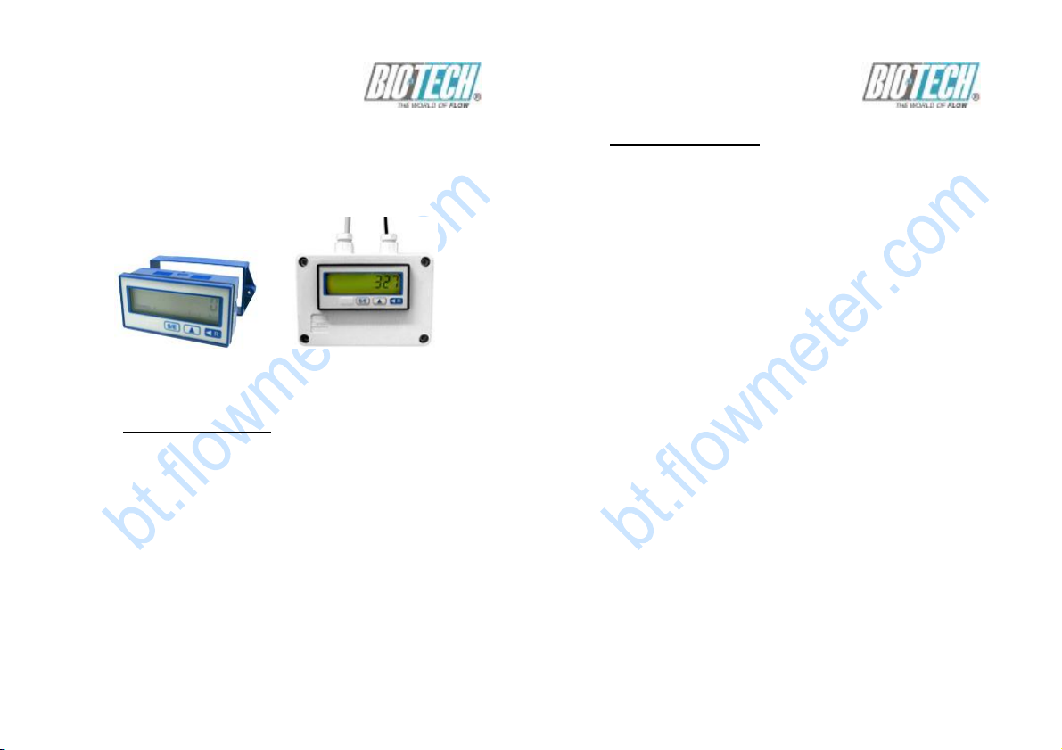
ARS - Totaliser Model
260 / 260-EC-01
Type 260-A
Table of Contents
1. Safety Instructions
2. Product ID - Dimensions
3. Function Description
4. Installation – Battery Replacement
5. Programming
6. Technical Data
7. Spare Parts
Type 260-EC-01
Seite 1
The world of flow
1. Safety Instructions
This instrument has been manufactured in accordance
with the applicable state of the art and meets all safety
regulations as shipped from the factory. Installation and
startup must be performed by qualified electricians only!
Operate instrument only when properly installed!
If safe operation can no longer be ensured, disable the
instrument and secure it against unauthorized operation.
Prevent injury to people or damage to property due to
failure or malfunction of the equipment through additional
safety measures such as limit switches, protective
equipment, etc. .
Read the Instruction Manual carefully before startup!
Seite 2
The world of flow
2. Product Identification – Dimensions
Seite 3
The world of flow
Seite 4

The world of flow
3. Function Description
This instrument can be used as a rate meter and as a
pulse counter.
The instrument has been pre-programmed in the factory
and must be adapted to your process for both the rate
meter function and pulse counting (see Section 5 –
Programming).
The instrument is ready for operation when the
programming input is not wired. You can switch
between Rate meter and Pulse Counter displays
using the S/E key during operation at any time.
The instrument has two counter inputs. Use counter
input A (“High” active) for rate meter with pulse
sequences up to 10 kHz; use input B (“Low” active
or “High” active) for pulse counter with pulse sequences
up to 30 Hz or 10 kHz.
The backlighting is activated and load on the internal
battery is reduced by applying an external supply
voltage of 24 VDC.
Seite 5
The world of flow
All stored data is lost when the battery is replaced.
The message “260_ xx” (xx for software
version number)
appears after the new battery is installed.
The instrument
is ready to operate after the S/E key is depressed,
which activates the factory programming.
Rate meter
The rate meter operates by the principle of period
length measurement with ARS (Auto Range System).
You can adapt the display to your operation using
the programming sequence:
1. Input the physical unit of the rate meter
(time basis)
2. Select accuracy
3. Set sensor pulse constant, and
4. If necessary, program a suitable scaling
factor.
ARS helps minimize display process-related fluctuations
depending on the selected accuracy, rounds off the
displayed value, and sets the decimal point automatically.
Seite 6
The world of flow
Measurement starts with the active edge at the counter
input A. After the measurement time (1 sec) has elapsed,
the measurement is completed with the next active edge,
and the value is displayed in CHANNEL A.
If no active edge appears within the “time out” period
you have programmed, the rate meter is reset to zero.
At frequencies > 1 Hz the average is calculated. When
the allowable count frequency is exceeded, the value
zero appears in the display; if the possible display range
(99999999) is exceeded, the display “E” appears.
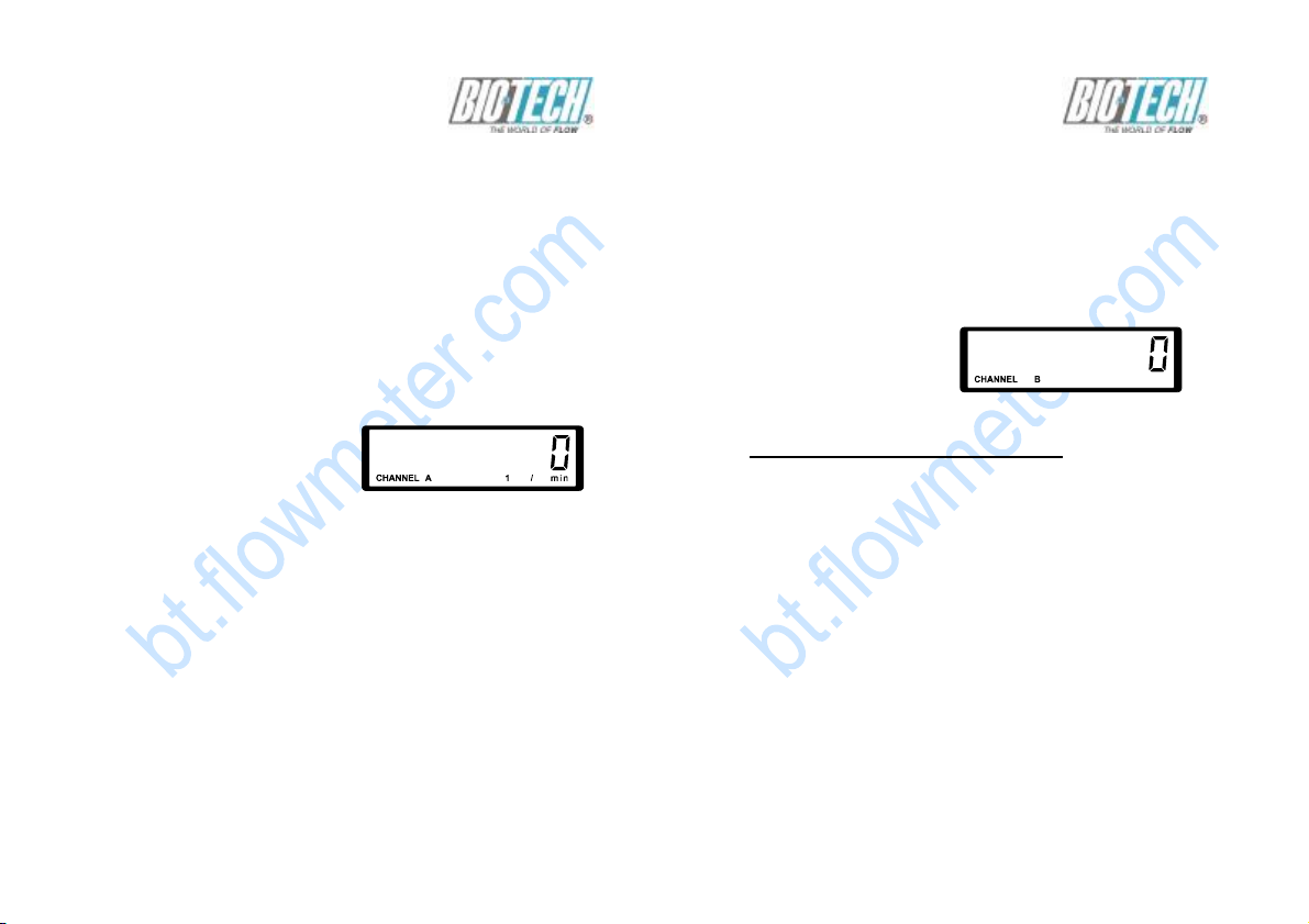
Display as delivered:
Pulse Counter
The pulses entering at the input B are added
and displayed
in CHANNEL B. The input B is programmable
as “HIGH
SPEED” - or “SLOW SPEED” - input. Further
you can scale
the display using an appropriate scaling factor.
Seite 7
The world of flow
You can also set a fixed decimal point and
program the pulse counter so
that you can reset it either through the regular
electrical
reset on the back or through the red R key on
the front.
After pressing the S/E key:
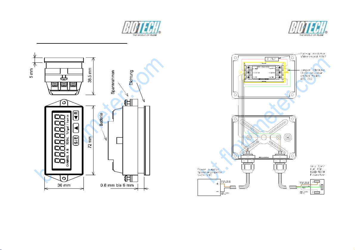
4. Installation – Battery replacement
After unpacking the instrument, remove the light-colored
frame from the back of the housing by simultaneously
bending both long sides of the frame slightly apart to
disengage them from the locking holes.
Then slide the housing through the cutout prepared in
the
front panel, attach the frame onto the back of the housing,
slide it all the way against the back of the front panel, and
carefully attach it with the two side screws to the front
panel.
In this way, you can compensate for different front panel
thicknesses. Class IP 65 front protection is achieved
through the seal integrated in the housing.
See the wiring diagram below for the electric wiring.
Seite 8

The world of flow
0 V
Programmier-
24 VDC Eingang
"LOW"-aktiv
"HIGH"- aktive Sensoren
"HIGH"-aktiv
Modell 260
24 VDC
The battery is accessible from the back of the
instrument.
There is a vertical notch under the middle of
the nameplate.
Cut through the nameplate there.
Then slide out the two-part battery cover to
one side along the guide grooves, and replace
the battery observing the correct polarity.
The instrument should not be connected to
24 VDC at this time!
Zähleingang B bei "LOW"-aktiv Programmierung (Kontakt nicht dargestellt)
"LOW"-aktiv
1
2
3
Rückstelleingang
für Backlight
Masse
Eingang A
Zähleingang B
eingang
Seite 9
4
5
6
"HIGH"-aktiv
IG
IG
The world of flow
5. Programming
The instrument can only be programmed by setting the
programming input PROG to 0 V.
Please note that this causes the pulse counter to be reset
internally.
After having set the programming input PROG to 0 V, the
following is displayed:
This display identifies the rate meter (Channel A); it cannot
be changed.
By repeatedly pressing the S/E key, you can cycle through
the individual menu items. The following figures correspond
to the factory settings of the instrument:
Physical unit, Accuracy,
Channel A Channel A
Sensor pulse constant, Scaling factor,
Channel A Channel A
Seite 10

The world of flow
Time-out period, Channel A
This display identifies the pulse counter (Channel B); it
cannot be changed.
Count frequency, Channel B Scaling factor, Channel B
The world of flow
2. Press ^ repeatedly if necessary:
Set the desired parameter.
3. Press S/E:
The parameter just set is confirmed and
displayed steadily.
4. Press S/E again:
You reach the next menu item.
See the possible settings allowed in each menu from the
following figures.
Flashing display elements are shown in a lighter color.
Physical unit, Channel A – Rate meter
Selecting the physical unit:
Decimal point, Channel B Reset-key enabled,
Channel B
You can make changes within each menu point as follows:
1. Press the <R key:
The parameter to be changed is activated, i.e., it begins to
flash.
Seite 11
Physical unit: 1/min Physical unit: 1/h
Physical unit: l/s Physical unit: l/min
Seite 12

The world of flow
Physical unit: l/h Physical unit: gal/s
Physical unit: gal/min Physical unit: gal/h
The world of flow
Sensor Pulse Constant, Channel A – Rate meter
You can set the pulse constant of the sensor in the range
of 1 to 99999.
The sensor pulse constant provides the number of pulses
per unit.
Example: Set a sensor constant of 500 pulses per
revolution
Press <R:
Physical unit: 1/s
Accuracy, Channel A – Rate meter
Setting measurement accuracy. See also page 13.
Accuracy 1% Accuracy 10%
Accuracy 0.1%
Seite 13
Press ^ 10 times: Press <R twice:
Press ^ 5 times: Press S/E:
Seite 14

The world of flow
Scaling factor, Channel A - Rate meter
You may set the scaling factor (SF) in the range of 0.0001
to 99.9999 as explained for setting the pulse constant.
The scaling factor is used when converting one physical
unit to another (e.g., diameter to perimeter, liters to gallons).
Time-out Period, Channel A - Rate meter
You can set the desired timeout period (time out) after
which the display is reset to zero if the operating frequency
is so low (or zero) that the measuring time would be
intolerably long.
The timeout period can be set in the range of 1s to 99s.
Example: Set timeout period to 10s
Press <R:
Press ^ 5 times: Press <R:
The world of flow
Count Frequency, Channel B – Pulse Counter
maximum frequency 10 kHz maximum frequency 30 Hz
Scaling Factor, Channel B – Pulse Counter
You can set the Scaling Factor in the range of 0.0001 to
99.9999.
Set the scaling factor as described under Scaling Factor,
Channel A.
Decimal point, Channel B – Pulse Counter
Press ^: Press S/E:
Seite 15
Seite 16

The world of flow
Reset Key enabled, Channel B – Pulse Counter
Reset key enabled Reset key disabled
If you have not enabled the reset key, the string “TOTAL“
is displayed.
Having completed the programming, disconnect the
programming input PROG from 0 V.
Please note that only the parameters confirmed with S/E
are accepted.
6. Technical Data
Displays
Special LC display with dimension line, 8 digits, 10 mm
digit height, pre-decimal point zero suppressed.
Display Capacity: Rate meter 99999999
Automatic decimal point
Pulse counter 99999999
Programmable decimal point
Accuracy
Period measurement accuracy:
Programmable to 0.1%, 1%, or 10% (corresponds to a
minimum resolution of 4, 3, or 2 digits, respectively).
Seite 17
The world of flow
Power Supply
internal lithium battery 3.6 V / 1.2 Ah
Average battery life 5 years
LED – Display backlighting
The LED display backlighting must be operated with
external voltage connected to 24 VDC and 0 V screw
terminals.
External Voltage: 24 VDC max. residual ripple 5%
absolute limits 19 to 30 VDC
Electromagnetic Compatibility (EMC)
Interference emission EN 55011 Group 1 Class B
Interference strength EN 50082-2
EN 61010-1 Measuring Insulation Voltage
100 Veff, Contamination Class 2, Surge Category III
DIN VDE 0411 Protection Class
Protection Class II
Electrical Connection
Terminal screw connection, P Phillips screws, size 1
max. lead section 2 x 1.5 mm²
min. lead section 2 x 0.2 mm²
IEC 529 Protection Class
IP 65 front
Temperature / Humidity range
Operating temperature range - 10°C to + 50°C
Storage temperature range - 20°C to + 70°C
Temperature / Humidity 90% relative humidity @ 38°C
Seite 18

The world of flow
IEC 68-2-6 Vibration Strength
Variable frequency range 10 to 500 Hz
0.35 mm or 5 g amplitude 10 Frequency
cycles per axis
Dimensions
Frontal dimensions 36 mm x 72 mm
Total depth 38.5 mm
Fastening
Front panel mount via frame
Front panel thickness 0.8 mm to 6 mm
Front panel cutout DIN 43700
33 +0.6 mm x 68 + 0.6 mm
Weight
approx. 95 g
Housing Material / Combustibility
PC plastic
Combustibiity V0 under UL Standard 94
Inputs
Counter Input A (Rate meter)
Pulse shape any
“HIGH - SPEED“ input “High” active
Signal level L<= 1 VDC H>= 5 VDC
Seite 19
The world of flow
Max. voltage amplitude ± 30 VDC
Input resistance approx. 39 kOhm
Max. frequency (pulse duty factor 1:1) 10 kHz
min. pulse time 50 µs
min. pulse pause 50 µs
Active edge High/Low
Counter Input B (Pulse Counter)
Pulse shape any
Programmed as “HIGH - SPEED” input “High” - active
Signal level L<= 1 VDC H>= 5 VDC
Max. voltage amplitude ± 30 VDC
Input resistance approx. 39 kOhm
Max. frequency (pulse duty factor 1:1) 10 kHz
min. pulse time 50 µs
min. pulse pause 50 µs
Active edge High/Low
Programmed as “SLOW – SPEED” input “Low” - active
Signal level L<= 0 VDC H>= 5 VDC or open
Max. voltage amplitude ± 30 VDC
Input resistance approx. 1 MOhm
Max. frequency (pulse duty factor 1:1) 30 Hz
min. pulse time 16 ms
min. pulse pause 16 ms
Seite 20

The world of flow
Active edge Low/High
Reset Input R (Pulse Counter)
Pulse shape any
Signal level L<= 0 VDC H>= 5 VDC or open
Max. voltage amplitude ± 30 VDC
Input resistance approx. 1 MOhm
Static response ”Low” - active
min. pulse time 65 ms
Programming Input PROG
Static response “Low” active
Input open Operating mode
Input connected to “0 V” Programming mode
7. Spare Parts
Lithium battery Art.-Nr.: 82202233
Technische Änderungen vorbehalten Stand 7.2011 We reserve the right to make technical changes without notice.
B.I.O-TECH e.K. | Zeitlarner Str. 32 | D- 94474 Vilshofen | Germany
Tel: +49 (0) 8541-91 00 47 | Fax: +49 (0) 8541-96 89 98 0
E-Mail: info@btflowmeter.com | Internet: www.btflowmeter.com
Seite 21
 Loading...