

Page 1
Biotage® VacMaster™ 10 & 20
Sample Processing Station
Operation Manual
© Biotage 2013
Page 2
CONTENTS
3 Introduction
4 Principle of Operation
6 Installation
8 Routine Operation
9 Solid Phase Extraction
12 Maintenance and Troubleshooting
12 Warranty
13 Ordering Information
Important Information
In the interest of safety, the Biotage® VacMaster™ is
thoroughly tested at high vacuum. This involves a series of
cycles from low vacuum to nominal full vacuum followed by
a final ‘hold’ phase at normal full vacuum. As such, we have
the utmost confidence in the quality of this product.
However, as with all glass vessels under vacuum, there is
a risk of implosion particularly if the unit is subject to any
sharp knocks or scratches. With this in mind, please follow
the safe working practices detailed below.
Safe Working Practices
1. Do not use the VacMaster at a vacuum greater than
minus 20” Hg (-0.68 bar).
2. Always wear eye protection when using the VacMaster
under vacuum. As with all glass laboratory equipment
operated under vacuum, we consider it prudent to
operate the unit behind a suitable safety screen.
3. Avoid knocking or scratching the VacMaster with any
sharp or heav y object.
4. If the VacMaster glass tank is dropped, scratched or
damaged in any way, we strongly recommend that it
should be replaced.
While we make ever y effor t to ensure the quality of the
VacMaster, misuse or damage incurred in use can seriously
compromise the structural integrity of the product.
Consequently, IST Ltd can accept no liability for injury or
damage caused by the VacMaster or its accessories.
©2013 Biotag e
Trademark Acknowledgement
Biotag e, Biota ge ZIP, Advancer, Advanc er Kilo batch, Adv ancer 350, A FFINILU TE, Ende avor, EVOLUT E, EVOLU TE EXPR ESS, Exp loraS ep, Firef ly desi gn, FLA SH+, FlashMas ter, FlashVac, Ho rizon,
HPFC, HP-S IL, HP-Sphe re KP-Sph ere, ZIP-S phere, In itiator, Initia tor+, Initiator+ A lstra, In itiator+ Ro bot 8, Initi ator+ Robo t 60, Initiato r+ SP Wave, Isol era, Isol era Pri me, Isole ra One, Is olera Fo ur,
Isoler a LS, Iso lera Dalt on, Isole ra Spek tra, Iso lera Sp ektra L S, Isole ra Spek tra One, I soler a Spekt ra Four, ISOLU TE, IST, IST des ign, KILOP REP, KP-C18-HS, K P-C18-WP, KP-C4-WP, KP-NH, K P-Sil,
MIP4SPE, MIP Ru le of 6, MIP[4]Proce ss, MIP[4]Prote ins, PathF inder, PRES SURE+, PRESS URE+ 48, PR ESSUR E+ 96, QuECh ERS, Rapi dTrace, Rap idTrace+, Resol ux, Robot 8, Ro bot 60, Samp let, SIM,
SNAP, SNAP Ultr a, SP1, SP4, SP Wave, SPE D ry , SPE Dr y 96, SPE Dr y 96 Dual, S yro Wave, SPx , TurboVap, VacMas ter, V-10, ZIF, ZIF-SIM, ZIP-Sphe re, 1-Point Sup port .
2 Biotage® VacMaster™ Manual© Biotage 2013
Other pr oduc t and comp any names me ntione d herein m ay be trade marks o r regis tered t rademar ks and/or s ervic e marks o f their re spec tive owner s, and are u sed only f or expla nation an d to the
owners ' benef it, witho ut intent t o infrin ge.
Page 3

Introduction
About the Biotage® VacMaster
The Biotage® VacMaster™ is a state-of-the-art sample processing
station. It incorporates innovative design features that make
simultaneously processing multiple samples easier than ever
before. For scientists working with biological f luids, these
features and operating procedures provide a safe system. The
VacMaster has 10 or 20 ports with disposable stainless steel
needles that accept any male luer sample preparation product. A
PTFE needle or combined needle stopcock are available for iner t
sample deliver y. The design features, materials of construction
and full range of accessories mean that the VacMaster meets the
needs of scientists involved in multiple sample processing in
solid phase extraction (SPE) or combinatorial chemistry application work.
Included components
»
A glass tank fitted with a rotating vacuum
outlet valve with a drain tube
»
A PTFE lid fitted with 10 or 20 stainless steel needle retainers
»
A vacuum gauge and controller with coarse
and fine adjustments mounted to the lid
»
A complete collection tube rack fitted with 10, 12
or 16 mm plates (plus 27mm for VacMaster-10)
™
»
A package of 10 or 20 stainless steel
needles with port sealing plugs
Optional accessories
»
Additional rack plates for 10, 12, 16, 27mm (Vac-10)
collection tubes or a blank plate for customization
»
A spare glass tank with vacuum outlet fitting
»
PTFE T-type valve for switching between two tanks
»
PTFE stopcocks
»
PTFE needles or combination needle stopcocks
»
Combined PTFE needle stopcock designed for
combinatorial chemistry applications where the stopcock
must be used under positive pressure conditions
»
VacMaster LVE accessories for the extraction of
multiple large volume water samples using both
polypropylene and glass ISOLUTE SPE columns
»
VacMaster compatible glass and polypropylene columns
with associated frits for combinatorial chemistr y
applications (details contained in the IST catalogue)
Specifications
Materials
Lid PTFE
Rack Ultra high molecular weight polyethylene (UHMW PE), polypropylene (legs)
Waste Outlet PTFE
Vacuum Gauge Various
Controller Arm Assembly Delrin
Tank Glass
Rack Plates Ultra high molecular weight polyethylene (UHMW PE)
Needle 316 Stainless Steel
Needle Retainer PTFE
Vacuum release valve Brass
Details
Maximum Applied Vacuum minus 20” Hg (-0.68 bar)
Sampling Ports 10 on VacMaster-10, 20 on VacMaster-20
Collection Rack for 10, 12, or 16 mm collec tion tubes (or 27 mm for VacMaster-10) (specified when ordering) or a blank plate
for customisation
3
Page 4

Principle of Operation
The Biotage® VacMaster™ applies a vacuum to the outlet of an
SPE column to assist in the extraction of aqueous or viscous
samples or to simultaneously process multiple samples. The
VacMaster uses a vacuum controller with fine and coarse
adjustment knobs and a vacuum gauge to set and monitor the
vacuum applied to the glass tank. The lid seals to the tank
with a gasket assisted by the vacuum. Applying vacuum to the
tank and opening the stopcock will draw the sample or eluent
through the SPE column or other sample preparation product.
The sample or eluent collects in test tubes or vials held in the
rack below the deliver y tips. Alternatively, using the VacMaster
without a rack, the solvent can collect in the bottom of the tank.
The glass tank has a vacuum outlet f itting that can be oriented
two ways. With the fitting is turned up, solution will remain in
the tank below the level of the outlet fitting. When the fitting is
swivelled down, waste fluids in the tank f low into a collection
trap for proper disposal.
Features
Easy to access stopcocks and room for large volume columns
The VacMaster is available with 10 or 20 places. With generous
spacing between positions, you can use ever y place every time,
even with stopcocks and large volume columns. The VacMaster
10 can accommodate up to 10 x 70 ml columns. The VacMaster
20 can accommodate up to 20 x 25 ml columns.
A rack system that is easy to adjust to
a variety of collection tubes
The continuously adjustable rack system uses unique threaded
rods to secure the rack plates where you need them. Rack plates
are available for 10, 12, and 16 mm diameter tubes as standard
(and 27 ml for VacMaster-10 only). Conversion from one size
tube to another is easy. Just purchase the low cost plates,
release the top nut and replace the plates. However, customization is easy with blank plates drilled to the required diameter.
The maximum tube diameter possible with the VacMaster-10 is
27 mm (accommodates scintillation vials), and VacMaster 20 is
23 mm (order specially).
Needles with easy to use stopcocks that
do not contaminate samples
The one piece needle design with a straight though flowpath
will not trap samples or eluents which could contaminate the
subsequent sample. The disposable stainless steel needles
are 316 stainless and will not corrode like stainless-steel-cladcopper needles. PTFE retainers hold the stainless steel needles
in place, so they are easy to remove and replace. The iner t
construction of the PTFE needle or combination needle stopcock
eliminates plasticizer contamination and ensures smooth
stopcock operation. Tapered PTFE tips eliminate overspray and
direct the sample and eluent into the collection tube. All of the
needles are securely threaded into the manifold top so they will
not pull out when removing the SPE column. For combinatorial
chemistr y applications which require a small positive pressure
to be applied to the column reservoirs, a special positive
pressure compatible combined PTFE needle stopcock is available (see page 17 for ordering information).
Materials of construction that will not contaminate samples
The VacMaster is manufactured from high quality materials
that will not contaminate the samples being processed. The
materials include glass, PTFE, UHMW polyethylene, polypropylene, and 316 stainless steel. The thick walled glass tank
provides a clear view of the extraction process.
Vacuum controllers that will not become
contaminated or corrode
The precision made vacuum controller with gauge provides
excellent sample flow control. The vacuum regulator, placed on
the lid, is easy to see and control. Column eluents will not pass
by and contaminate or corrode the regulator.
Safe, easy way to handle biological and
hazardous sample matrices
With the lid-mounted vacuum controller, it is possible to use
one tank to process the samples and dedicate a second low
cost tank for the elution step. Thus, the second tank can remain
uncontaminated. Additionally, the vacuum outlet fitting on the
glass tank can be oriented two ways. Turn the fitting up to close
the outlet and add the appropriate sterilization solution to the
tank to neutralize the collected biological solutions. Swivel the
fitting down to direct the waste fluids out of the tank into a side
arm collection flask for proper disposal.
4 Biotage® VacMaster™ Manual© Biotage 2013
Page 5
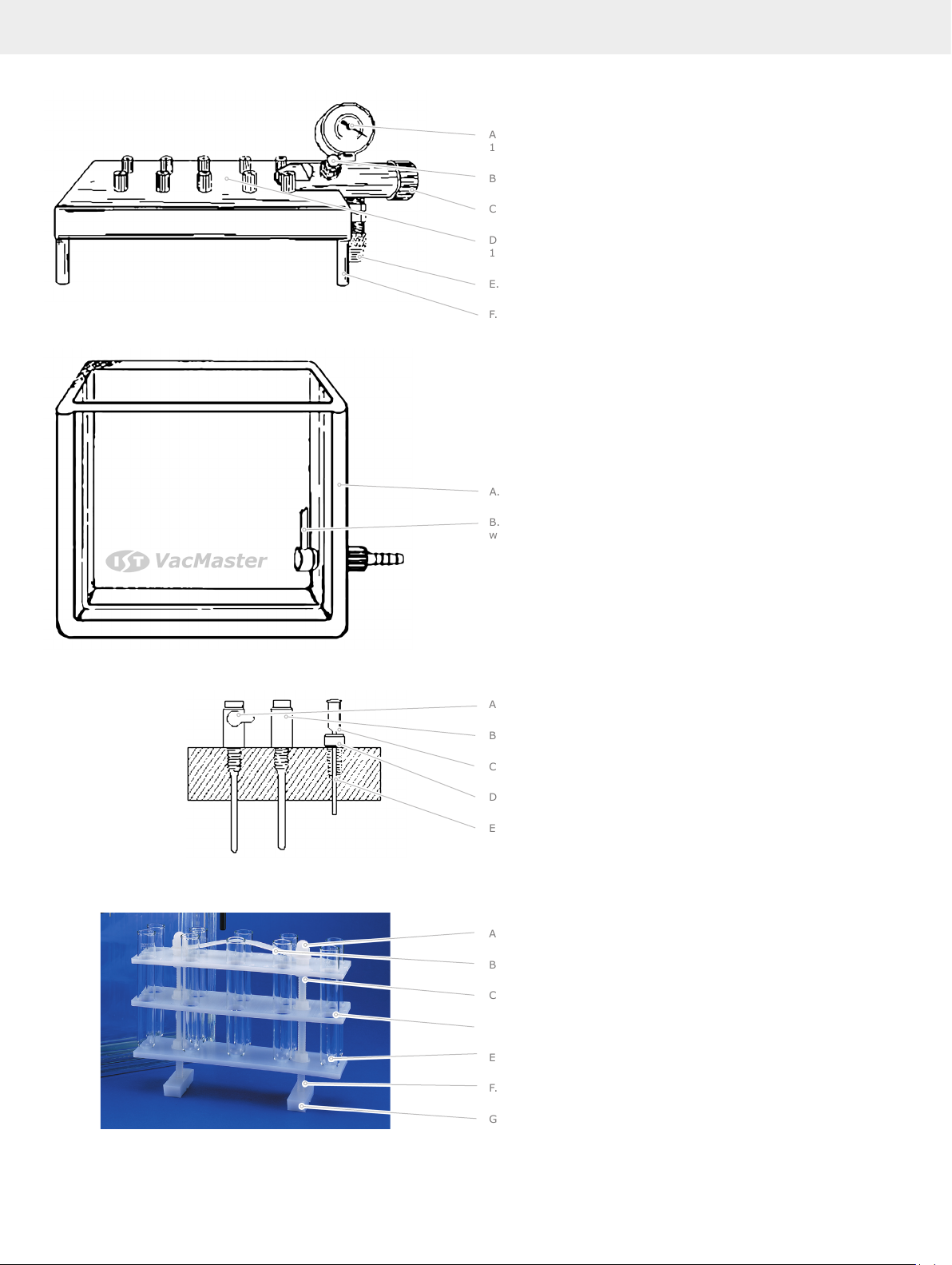
Figure 1. Lid
A. Vacuum gauge (p/n 0018) mounted on controller arm ass embly (p/n
121- 0 025 )
B. Fine control valve (p/n 121-0020)
C. Coar se vac uum control valve (Open or Closed)
D. PTFE lid (for replacement lit complete with all fittings, orde r p/n 1211045 (VacMaster-10) or 121-2075 (VacMaster-20)
E. Vacuum r elief valve (p/n 121-0019)
F. Lid leg (p/n 121-0026)
Figure 2 . Glass tank. For replacement tank complete with fittings, order
part # 121-1039 (VacMaster-10) or 121-2068 (VacMas ter-20)
A. Thick walled glass tank
B. For replacement waste outlet fittings, order p/n 121-0029 (VacMaster
waste outlet (complete)
Figure 3. Needles
A. PTFE stopcock needle unit (p/n 121-0001)
B. PTF E needle unit (p/n 121-0002)
C. Stainless s teel needle (p/n 121-0003)
D. Stainless steel needle retainer (p/n 121-0004)
E. Thre aded ne edle po rts
Figure 4 . VacMas ter collection tub e rack
A. Rack dome nut (p/n 121-0040)
B. Rack handle (p/n 121-0043 (VacMaste r-10), 121-0044 (VacMaster-20)
C. Rack nut washe r (p/n 121-0041)
D. Top / mid plate (various p/n)
E. Lower plate (various p/n)
F. Rack leg (p/n 121-0045)
G. Rack foot (p/n 121-0042)
5
Page 6

Installation
Unpacking
The Biotage® VacMaster™ is shipped with all accessories in one
box. Before using the VacMaster, unpack all the components
carefully. Do not discard any packing material until you have
checked the VacMaster and accessories. We suggest that you
store the packing materials to have them available for storage
or future shipments.
If you find any damage to the unit or the box, contact the
shipping company that delivered the VacMaster and file a claim.
Please contact IST Ltd via your local distributor for assistance in
repairing or replacing the product.
What You Will Need
In addition to the VacMaster and the accessories, you will need
the following to use the VacMaster.
6 Biotage® VacMaster™ Manual© Biotage 2013
Vacuum source
Vacuum control unit with integral vacuum
generator (Part number 121-9602)
Converts standard laboratory compressed air supply to vacuum
which is ample for processing samples on a VacMaster. The unit
has a small footprint, and has low noise emissions compared
to a standard vacuum pump. Connect the vacuum source to the
vacuum outlet fitting on the side of the glass tank using vacuum
tubing. Place a trap in the vacuum line to collect any liquid for
proper disposal.
Vacuum pump
We recommend that you use a vacuum pump that is oil free and
generates no more than minus 20” Hg (-0.68 bar). Connect the
vacuum source to the vacuum outlet fitting on the side of the
glass tank using vacuum tubing. Place a trap in the vacuum line
to collect any liquid for proper disposal.
Page 7

Suitable vacuum sources, tubing and a 1L polypropylene trap
are available from IST (see pages 17 and 18 for ordering details).
SPE columns
Select columns capable of retaining and eluting the compounds
of interest. If you are uncertain as to which column to use,
please contact your local IST distributor for technical advice or
assistance.
Collection tubes
Select collection tubes suitable for your rack and your intended
use. Racks are available to accommodate 10, 12, or 16 mm tubes
(and 27mm for Biotage
collection tube, purchase blank plates and drill them to f it any
collection tube.
®
VacMaster™-10). If using a different
Installing the Needles
The stainless steel needle retainers are securely threaded into
the lid when the VacMaster is assembled, and f itted with stainless steel needles.
PTFE needles or combination needle stopcocks can be used in
place of the stainless steel needles. To install these needles,
remove the stainless steel needle retainers by rotating them
counterclockwise until they are free from the lid. Place the new
PTFE needle or combination needle stopcock into position and
turn clockwise until firmly seated against the lid. Use caution to
thread the needle correctly. Misthreading or overtightening the
needles or needle retainers could damage the threads on the
needles, retainers, or lid ports.
Installing Collection Tubes
The collection tube rack comes pre-assembled and should be
ready to use with most collection tubes. Simply place the collection tube in the rack under each position you intend to use. If
your tubes do not fit in the rack or are not securely held by the
collection tube rack, you may need to replace the rack plates or
adjust the rack.
Replacing Collection Tube Racks
The VacMaster is shipped with tube racks for 10, 12 or 16 mm
tubes (or 27mm for VacMaster-10), specified with each order.
Compare the par t number of your VacMaster with the ordering
information in the appendix to determine which rack you have.
Alternatively, measure the diameter of the opening in the
top collection tube rack plate. Additional 10, 12, or 16 mm (or
27mm for VacMaster-10) collection tube racks or rack plates are
available. Blank plates can be drilled to meet other collection
tube requirements. Part numbers and ordering information are
in the appendix.
To convert collection tube racks:
1. Remove all collection tubes from the rack and remove the
rack from the glass tank.
2. Grip top plate securely, and unscrew dome nuts
counterclockwise.
3. Lift off carr ying handle.
4. Each plate is held in place by nut washers positioned above
and below the plate. To remove a plate: unscrew (counterclockwise) nut washers from above the plate, and lift off
plate. Unscrew and remove nut washer from below plate
5. Remove the top and middle collection tube rack plates
and replace with appropriate plates. Plate height can be
changed by adjusting the position of the upper and lower
nut washers for each plate. Ensure that the nut flange is
adjacent to the plate, and that all nuts are tightened to
plates for rigidity.
6. Replace carrying handle.
7. Replace dome nuts. Use caution to thread all nuts correctly.
Misthreading could damage the threads.
Adjusting the Collection Tube Rack
If your collection tubes are not securely held by the collection
rack, the rack may need adjustment. Each plate is held in place
by nut washers positioned above and below the plate. When
adjusting the rack, remember to keep all plates level. Refer to
Figure 3 while adjusting the rack.
Bottom, middle and top plates
To raise the plate: turn the nut washers above the plate counterclockwise until they reach the correct height. Turn the nut
washers below the plate counterclockwise to raise the plate and
tighten to secure in position.
To lower the plate: turn the nut washers below the plate clockwise until they reach the correct height. Turn the nut washers
above the plate clockwise to lower the plate and tighten to
secure in position.
Handle and dome nuts
Securely tighten the dome nuts above the handle at the top
of the rack legs at all times, to provide a secure handle for
inserting or removing the rack from the tank.
7
Page 8
Routine Operation
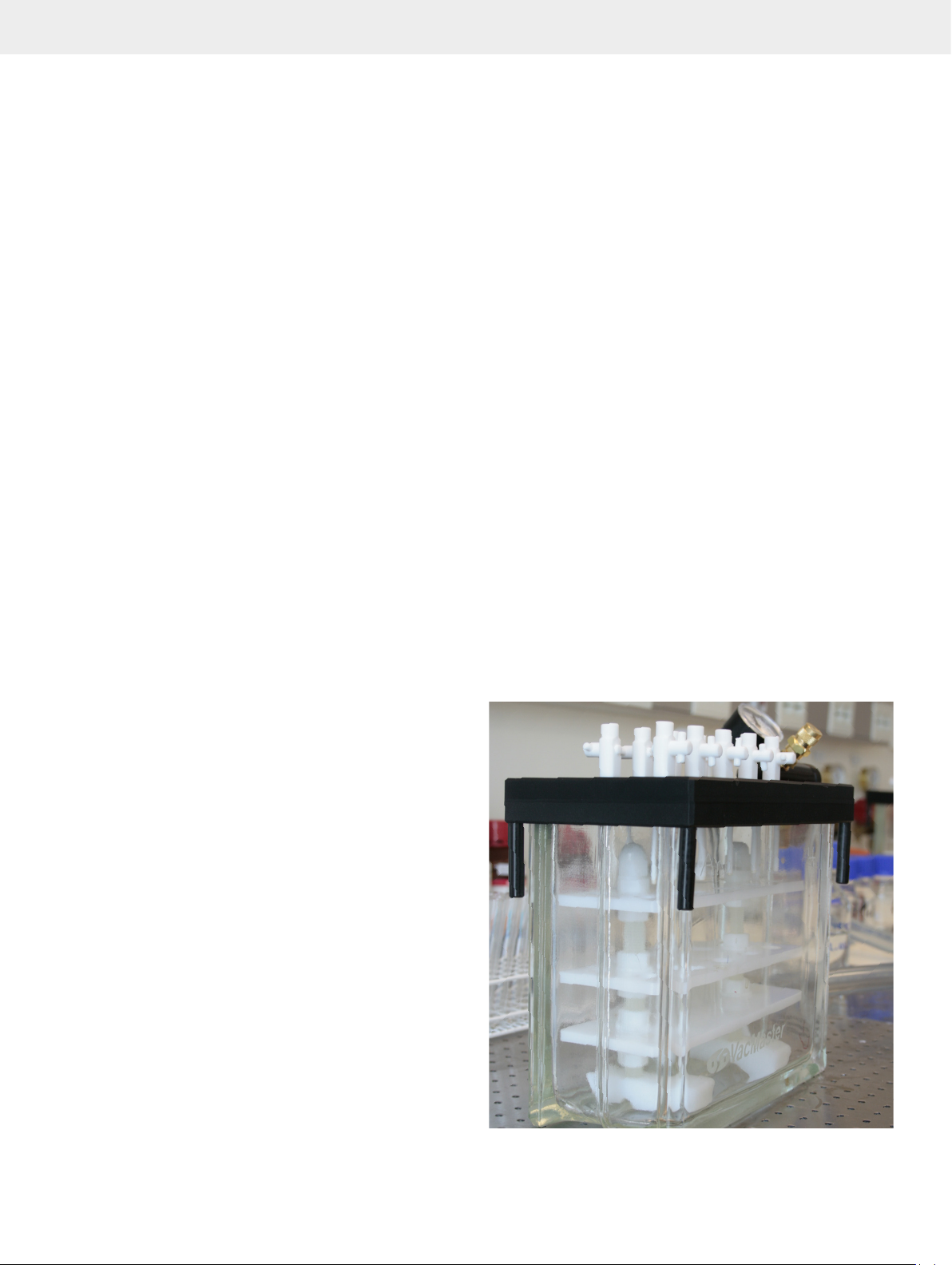
Using the Vacuum Control and Gauge
1. Place the SPE columns in the needle ports and add solvent
or sample to the column reservoirs.
2. Open the stopcocks if they are being used. Open both the
coarse and fine vacuum control valves on the Biotage
VacMaster™ lid. The coarse control valve is open when it is
turned counter-clockwise. The fine control is open when
turned fully counter-clockwise.
3. Apply vacuum to the VacMaster manifold from the vacuum
source.
4. Close the coarse vacuum control valve by turning clockwise. Adjust the vacuum by turning the fine control knob
clockwise until the desired vacuum level and flow rate
is obtained. Monitor the vacuum level on the vacuum
gauge next to the control knobs. A vacuum level of minus
3 to minus 5” of Hg is satisfactory for most applications.
Establishing the vacuum level needed for optimum flow
rates through the SPE column is an important part of every
method development procedure.
Note: Do NOT exceed minus 20” Hg (minus 0.68 bar) at
any time. Vacuum levels above minus 20” Hg significantly
increase the risk of implosion of the glass tank and serious
personal harm.
5. If stopcocks are being used on the needle por ts, the flow
rate through each SPE column can be individually regulated
by the stopcock position.
6. When the desired volume of solvent or sample is drawn
through the tube, close each stopcock if they are being
used. Next open the fine control knob by turning it counterclockwise. Open the coarse control valve by turning
counter-clockwise. Turn off the vacuum source.
7. Continue the processing by adding the next solution to each
SPE column reservoir. Repeat procedure from step 2 above.
®
Using the Biotage® VacMaster™ with
Biological or Hazardous Materials
When processing physiological fluids, tissues, environmental,
or other hazardous samples, it is advantageous to purchase a
second low cost tank to dedicate to the analyte elution step.
This second tank can remain uncontaminated. A single vacuum
source can be used by placing a PTFE T-valve in the vacuum line
between the vacuum source and each manifold. The first tank
can be used without a collection tube rack to collect the liquids
exiting the columns during sample application and interference
elution steps. By turning the waste outlet fitting up, liquids will
remain in the tank. An appropriate sterilization solution (for
example, bleach) can be added to the tank to neutralize the
collected biological liquids. Swivel the fitting down to direct
the waste fluids out of the tank into a collection flask for proper
disposal. Or pour the waste fluids from the tank into the appropriate waste container.
After the samples have been loaded on the SPE columns and
the interferences have been eluted, the VacMaster lid can be
removed from the first tank and placed on the second tank.
Then the samples can be eluted into collection tubes in the
clean second tank.
Using the Waste Outlet Fitting
The waste outlet fitting inside the glass tank of the VacMaster
can be oriented in two positions. When the fitting is positioned
so the drain tube is up, liquid collects in the tank. When the
fitting is turned down, any liquid that reaches the drain tube
will be removed by vacuum from the tank though the outlet
fitting. A collection flask in the vacuum line is essential with the
outlet fitting in this orientation to collect the evacuated liquid.
Without a trap, the liquid would enter the vacuum pump and
could damage the pump.
8 Biotage® VacMaster™ Manual© Biotage 2013
Page 9

Solid Phase Extraction
Sample preparation prior to instrumental analysis is often as
important to an assay as the instrumental analysis itself. This
is especially true when very low levels of detection are required
for compounds from complex matrixes such as physiological
fluids, tissues, food, agricultural products and environmental
samples. Solid phase extraction (SPE) is the most powerful
technique currently available for rapid, selective sample preparation. The versatility of SPE allows it to be used for a number of
purposes, such as:
»
Purification
»
Trace enrichment
»
Solvent exchange - analytes are transferred
from one particular matrix environment to
another, for example, aqueous to organic
»
Desalting
»
Derivatization - analytes are retained on a
sorbent, derivatized, then eluted
»
Class fractionation - a sample is separated into different
compound groups that share common properties
SPE offers many benefits and advantages over more traditional
sample preparation techniques (such as liquid/liquid extraction), including the following:
1. High recoveries of the analytes
2. Concentration of the analytes
3. Highly purified extracts
4. Ease of automation
5. Compatibility with instrumental analysis
6. Reduction in organic solvent consumption
7. No problems with emulsion formation
8. Simultaneous processing of multiple samples
9. Suitability to small sample sizes
As a result, the use of SPE has grown dramatically over the last
ten years, and continues to grow as the preferred technique for
state-of-the-art sample preparation.
SPE is a very simple technique to use, employing inexpensive,
disposable extraction columns. These columns are available in
a multitude of column sizes and sorbents. Please contact your
local IST distributor for assistance with column selection.
In principle, SPE is analogous to liquid/liquid extraction. As
a liquid sample passes through the SPE column, compounds
are ‘extracted’ from the sample onto the sorbent material in
the column. Interferences can then be selectively removed
from the column through the correct choice of ‘wash’ solvents.
Finally, an elution solvent recovers the desired analytes from
the column, resulting in a highly purified extract. This extract is
often significantly more concentrated than the original sample.
Alternatively, select an extraction column and elution solvent
combination that retains interferences on the sorbent, but
allows the analytes to pass through unretained.
®
ISOLUTE
particle size of 50μm. Although gravity can facilitate flow of
most organic solvents through the columns, for aqueous and
other viscous samples and solvents, a motive force must be
used to pass liquids though the columns. The most common
method is vacuum applied to the column outlet. The Biotage
VacMaster
purpose.
SPE columns contain sorbents with an average
™
vacuum manifold is specifically designed for this
®
Guidelines for the Use of Solid
Phase Extraction olumns
Successful use of SPE columns is relies on proper treatment of
the columns (and the original sample) through all stages of an
extraction. The following section offers general guidelines for
each step of an SPE procedure.
Column processing
»
Do not force liquids through the SPE column too
quickly. This is especially significant when performing
ion-exchange extractions, because too fast a flow can
cause analyte break-through (analytes pass unretained
through the column) or poor column equilibrium. One
to two milliliters per minute is a good starting point
for 100mg/1ml columns. For larger diameter columns,
proportionally higher flow rates can normally be used.
»
Ensure the analytes (compounds of interest) are in solution
and available for interaction with the sorbent. If the
sample contains particulate matter to which the analytes
adsorb, it is necessary to first desorb the analytes from
the particulate before a successful extraction is possible.
Similarly, if the analytes are chemically bound to large
molecules in the sample (for example, drug analytes
bound to sample proteins), this binding must be disrupted
in order to achieve high extraction efficiencies. This may
be accomplished in a variety of ways, such as adjusting
the pH or through the addition of an organic solvent.
»
Filter or otherwise remove sample particulates as necessar y.
Although SPE columns act as physical filters to a certain
degree, it is possible to plug the column frits, thus preventing
flow though the columns. Ensure that the analytes are not
adsorbed to the particulates being removed from the sample
prior to extraction! ISOLUTE
now available with an integral depth f ilter to help handle
particulate laden samples. Alternatively large diameter depth
®
SPE columns (sizes B-F) are
9
Page 10
filter reservoirs which can be attached to any SPE columns
are available. Details are contained in the IST catalogue.
Steps in solid phase extraction
A typical SPE procedure involves six basic steps:
1. Sample pre-treatment
2. SPE column solvation
3. SPE column equilibration
4. Sample application to the SPE column
5. SPE column washing (interference elution step)
6. Analyte elution from the SPE column
Sample pre-treatment
Proper sample pre-treatment involves preparing the sample
both physically and chemically for the solid phase extraction.
SPE works effectively only on liquid samples. Such samples
may require filtration prior to processing. Solid samples that
cannot be dissolved directly are typically homogenized,
followed by filtration (ensure the analytes are dissolved in
the initial extract to be processed with the SPE column).
Alternatively, extract solids with a liquid prior to SPE.
One of the primary goals of sample pre-treatment is to create a
sample whose chemistry promotes retention of the analytes on
the chosen extraction column. Chemical treatment of a sample
may involve:
»
sample dilution - to facilitate flow through the SPE
column by reduction of sample viscosity or ionic
streng th, and to enhance analyte retention
»
addition of a buffer - to control or change the pH of the sample
»
initial liquid/liquid extraction
SPE Column Solvation
In order for the sorbent in an SPE column to retain an analyte,
it is necessar y for a proper ‘phase interface’ to exist between
the sorbent and the sample. This solvation process is usually
the first step of an extraction, and involves passing methanol,
acetonitrile, or other organic solvent though the column. This
solvent ‘wets’ the phase, ensuring interaction with the sample
matrix. For example, a C18 phase is very hydrophobic, and
will not retain analytes from a 100% aqueous sample without
first being solvated. A typical volume of solvation solvent is
0.5–1.0ml/100 mg sorbent.
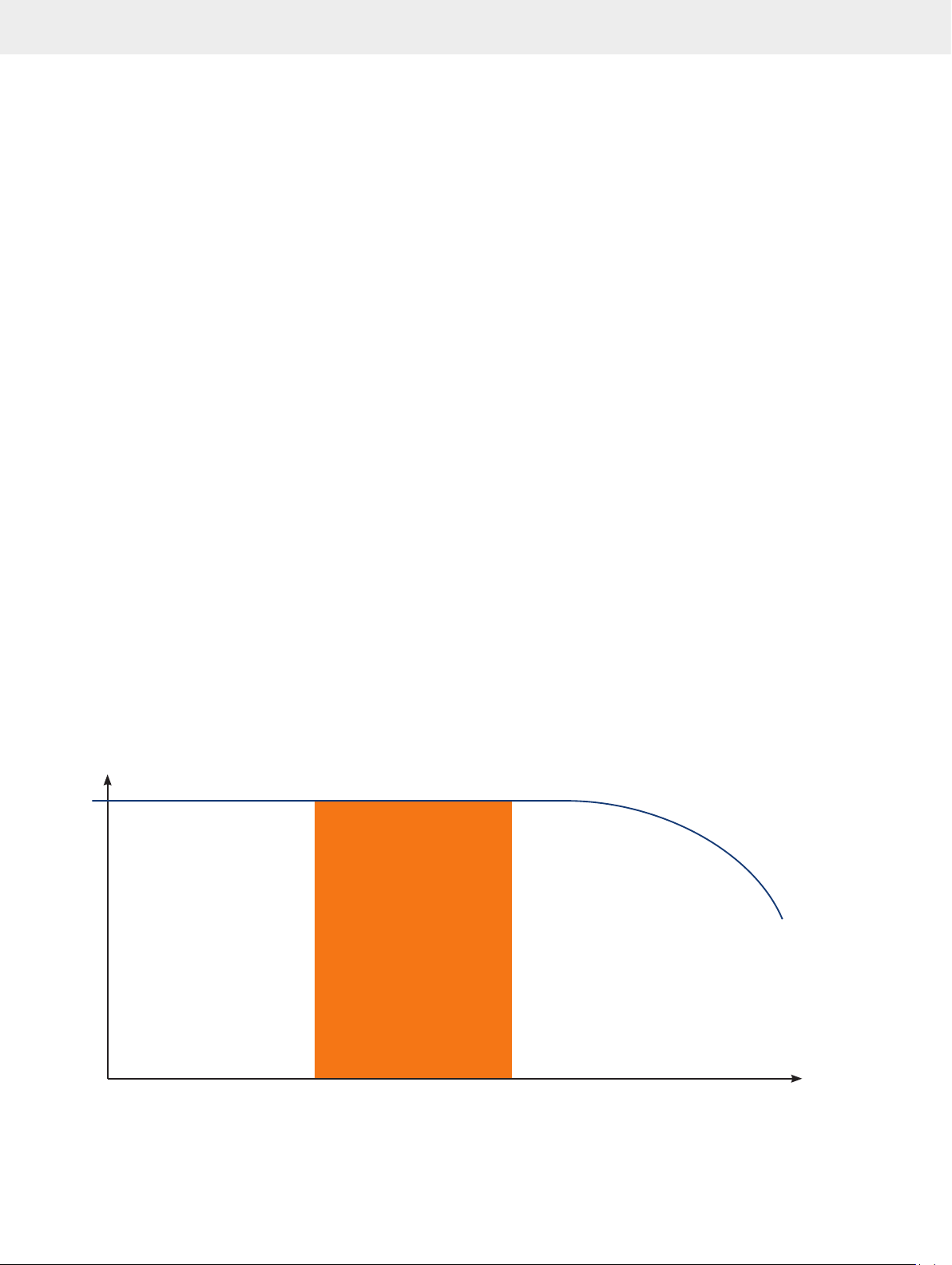
Recover y (%)
100
Figure 4 . Sample loading flow rate vs. extraction efficiency
Flow Rate
10 Biotage® VacMaster™ Manual© Biotage 2013
Page 11
SPE Column Equilibration
Following solvation of the column, and prior to applying the
sample, it is necessary to equilibrate the column. Equilibrate a
column by treating it with a solvent that is as ‘sample-like’ as
possible. For example, if the sample is a buffered physiological
fluid, it may be suitable to equilibrate the column with the
sample buffer. Conversely, if the sample is an organic solvent
extract, then the column should be equilibrated with the same
organic solvent. The equilibration step should put the bonded
phase in a condition that promotes analyte retention. A t ypical
volume of solvent is 1ml/100 mg sorbent.
Sample application to the SPE column
Apply the sample after solvating and equilibrating the column.
Again, it is very important to allow the sample sufficient time to
pass through the column (too rapid a flow may cause reduced
recoveries). See Figure 4. Establishing optimum flow rates is an
important part of the method development procedure.
SPE column washing (interference elution step)
After applying the sample to the column, perform one or more
solvent wash steps. The purpose of wash steps is to selectively
elute undesired compounds from the sorbent without eluting the
analytes of interest. Solvents in which the analytes are insoluble
are often very good choices for wash solvents. If the wash
solvent is immiscible with the solvent in which the sample was
applied, a drying step is necessar y. When using non-polar and
ion-exchange sorbents, pH control of the interference elution
solvent is of ten necessary for reproducible results. Control the
flow rate of the interference elution solvent. If the flow rate is
too high, the final extract may not be as clean as possible.
Analyte elution from the SPE column
The final step in SPE is to recover the desired analytes from
the extraction column. Do this by washing the column with
a solvent that can elute the analytes from the sorbent into a
suitable collection vessel. There are often many options for the
choice of elution solvent. The final selection may be influenced
by the ease of solvent evaporation or compatibility with the
final analytical technique. The typical minimum elution volume
is 250 μl / 100 mg sorbent. If the sample elution solvent is
immiscible with the preceding wash solvent, it is necessary to
use a drying step to avoid low recoveries. It is a prudent practice
to wipe each needle tip between the interference elution step
and the analyte elution to ensure extraction purity.
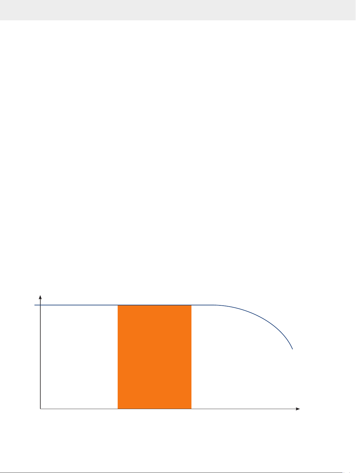
Flow control in the elution step can be important. Excessive
flow rates can result in reduced recoveries of analytes
(Figure5).
Recover y (%)
100
Figure 5. Analyte elution solve nt flow r ate vs. extraction eff iciency
Flow Rate
11
Page 12

Maintenance and Troubleshooting
If collection tubes are used routinely, the VacMaster will require
little or no cleaning. If the ‘two tank’ option is used for biological or hazardous samples, prompt removal and disposal of
the collected liquids will reduce the amount of routine cleaning
needed.
If the glass tank needs to be cleaned, please use water and
mild laboratory detergents. DO NOT use scouring powders or
pads, or anything else that would scratch or damage the tank.
Any damage to the glass tank can severely increase the risk of
implosion and serious personal harm.
Troubleshooting
Problem Cause Remedy
No liquid flow through
column
No vacuum No vacuum from source heck vacuum source
Solvent not flowing into
collection tubes
Liquid collecting in the
bottom of the glass tank
Tank lid will not close Collection tubes above tank rim Lower bottom plate of collection plate
Liquid collecting in vacuum Liquid is leaving tank Rotate waste outlet fitting up tubing
Liquid in the collection tubes
is disturbed when vacuum is
released
Column plugged Replace column
Filter s amples to remove particulate s. Use depth filter
Sample too viscous Dilute sample
Vacuum controller not adjusted properly Adjust fine and coar se control valves on VacMaster
Air entering thr ough unused por ts Use port sealing plugs in por ts without columns
Gasket on lid not sealing Replace gasket
Vacuum relief valve opened due to
vacuum > minus 20” Hg
Bent needles Replace or straighten needles
Stopcock (if used) is closed Open stopcock
Waste outlet fitting r otated up Rotate fitting down and install drain tube
No collection trap between manifold and
vacuum source
Air is entering tank above tubes Install air flow tube in right side of lid
Adjust vacuum source and control valves to lower vacuum and
restart
Install collection trap bet ween manifold and vacuum source
Warranty
Biotage products are warranted to be free from defects in
materials and workmanship for a period of ninety (90) days
from the shipment date. Under this warranty, Biotage will either
repair or replace products that are defective provided that the
product has not been misused or modified in any way.
While ever y effort is made to ensure the quality of the
Biotage® VacMaster™, misuse or damage incurred in use can
12 Biotage® VacMaster™ Manual© Biotage 2013
seriously compromise the structural integrity of the product.
Consequently, Biotage can accept no liability for injury or
damage caused by the VacMaster or its accessories.
Returns
Returns are accepted by prior authorisation. Please contact your
local Biotage distributor for a return authorization number.
Page 13

Ordering Information
Part No. Description Qt y.
VacMaster-10 for processing up to 10 sample s
simultaneously
121-1010 Complete with 10 mm diameter
collection tube rack
121-1012 Complete with 12 mm diameter
collection tube rack
12 1-10 16 Complete with 16 mm diameter
collection tube rack
12 1-10 27 Complete with 27 mm diameter
collection tube rack
VacMaster-20 for processing up to 20 samples
simultaneously
121-2010 Complete with 10 mm diameter
collection tube rack
121-2012 Complete with 12 mm diameter
collection tube rack
121-2016 Complete with 16 mm diameter
collection tube rack
Needles and stopcocks for VacMaster-10 and -20
121-0001 PTFE stopcock / needle unit 10
121-0002 PTFE needle unit 10
121-0003 Stainless steel needles 20
121-0004 Stainless steel needle retainer 10
121-0005 Port sealing plugs 30
121-0009 PTFE stopcock 10
121-0009-S PTFE stopcock- positive pressure 10
Large volume ex trac tion kits
Suitable for the simultaneous extraction of up to 10 large volume
water samples using the VacMaster SPE manifold. Four options are
available to cover the complete ISOLUTE product range. The kit
includes 10 numbered PTFE tubes fit ted to appropr iate adaptors.
121-20 9 0 VacMaster LVE kit for 1, 3 and 6ml
columns (A, B and C)
121-20 91 Vac Master LVE kit for 15 and 25ml
columns (D and E)
121-20 92 VacMaster LVE kit for 60ml columns
(F)
121-20 93 VacMaster LVE kit for 6ml glass
columns
121-20 9 4 VacMaster LVE kit for ISOLUTE-XL
columns
Components for VacMaster-10 and -20
121-0040 VacMaster rack dome nut
Part No. Description Qt y.
121-0041 VacMaster rack nut washer
121-0042 VacMaster rack foot
121-0045 VacMaster rack leg
Components for VacMaster-10
121-0043 VacMaster 10 rack handle
12 1-10 3 0 Silicone Lid Gasket
12 1-10 3 9 Spare glass tank with waste outlet
fitting
121-1045 Complete lid (tested)
12 1-11 32 VacMaster 10 rack 10mm tubes
12 1-11 3 3 VacMaster 10 rack 12mm tubes
12 1-11 3 4 VacMaster 10 rack 16mm tubes
12 1-11 31 VacMaster 10 rack 27mm tubes
12 1-11 35 VacMaster 10 top/mid plate 10mm
12 1-11 3 6 VacMaster 10 top/mid plate 12mm
12 1-11 37 VacMaster 10 top/mid plate 16mm
12 1-11 3 8 VacMaster 10 top/mid plate 27mm
12 1-1143 VacMaster 10 lower plate
Components for VacMaster-20
121-0044 VacMaster 20 rack handle
121-20 59 VacMaster 20 silicone lid gasket
121-20 6 8 Spare glass tank with waste outlet
fitting
121-2075 Complete lid (tested)
121-2161 VacMaster 20 rack 10mm tubes
121-2162 VacMaster 20 rack 12mm tubes
121-2163 VacMaster 20 rack 16mm tubes
121-2164 VacMaster 20 top/mid plate 10mm
121-2165 VacMaster 20 top/mid plate 12mm
121-216 VacMaster 20 top/mid plate 16mm
121-2173 VacMaster 20 lower plate
Vacuum Pump and Supplies
121-9 6 02 Vacuum control unit with integral
vacuum generator
121-924 0 Vacuum Pump, 240V / 50 Hz
121-9115 Vacuum Pump, 115V / 60 Hz
121-0 010 PTFE T-valve
121-20 95 VacMaster trap kit
121-20 9 6 Vacuum Flask with sidearm
121-20 97 Flask stopper with 1 tubing
connector
121-20 9 8 1.5m of vacuum tubing
121-20 9 9 Replacement gasket
13
Page 14
14 Biotage® VacMaster™ Manual© Biotage 2013
Page 15
Page 16

Your Complete
Partner for
Effective Chemistry
Biotage is a worldwide supplier of
instruments and accessories designed to
facilitate the work of laboratory chemists.
With our deep knowledge of the industry,
academic contacts and in-house R&D
teams, we can deliver the best solutions
to your challenges. We take great pride
in our flexibility and ability to meet our
customer’s individual needs. With strong
foundations in both analytical and organic
chemistry, we can offer the widest range
of solutions available on the market.
EUROPE
Main Office: +46 18 565900
Toll Free: +800 18 565710
Fax: +46 18 591922
Order Tel: +46 18 565710
Order Fax: +46 18 565705
[email protected]
©2013 Biotage. A ll right s rese rved.
All bran d and prod uct name s are tra demark s or regi stere d trade marks of t heir re spect ive compa nies.
The info rmatio n contai ned in this d ocumen t is subjec t to chan ge witho ut notice .
Part Numb er: UI303
© Biotage 2013
NORTH & LATIN AMERICA
Main Office: +1 704 654 4900
Toll Free: +1 800 446 4752
Fax: +1 704 654 4917
Order Tel: +1 704 654 4900
Order Fax: +1 434 296 8217
[email protected]
JAPAN
Tel: +81 3 5627 3123
Fax: +81 3 5627 3121
[email protected]
CHINA
Tel: +86 21 2898 6655
Fax: +86 21 2898 6153
[email protected]
To locate a distributor,
please visit our website at
www.biotage.com
 Loading...