

Page 1
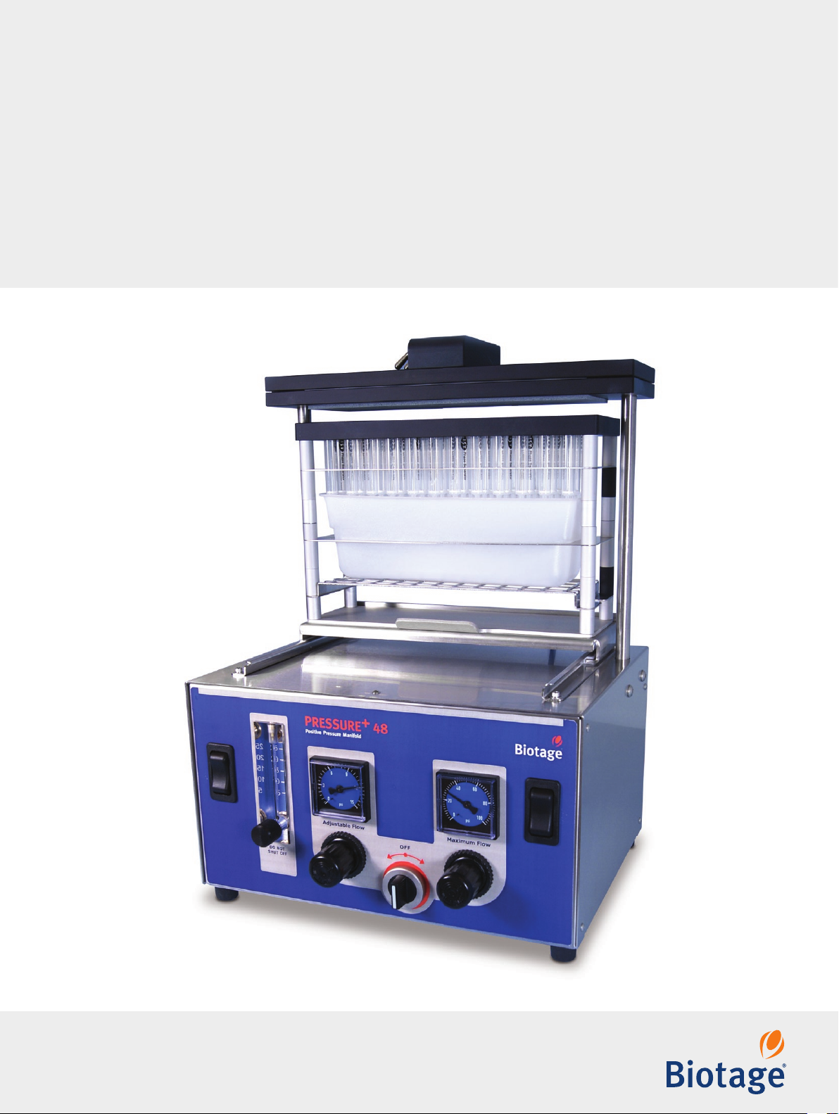
Biotage® PRESSURE+
User Manual
Page 2

Contents
Biotage® PRESSURE+
User Manual
CONTENTS
Safety
1 Intended Use
1 Education, Training, and Competence
1 Warranty and Liability
1 Service
1 Equipment Safety Standards
1 Labels
1 Safety Requirements
Installation
2 Site Requirements
2 Unpack and Install
System Description
4 Load the Columns
5 Flow Control
Operation
6 Step-by-Step Instructions
Maintenance
8 Replace the Sealing Gasket
8 Clean
General Information
9 Consumables and Accessories
9 Manufacturer
9 Contact Us
Biotage® PRESSURE+ 48 User Manual | © Biotage 2017
Page 3
Safety
Safety
Intended Use
Biotage PRESSURE+ 48 is intended for laboratory use only and
has to be operated by trained professionals. All operations must
be performed:
»
According to the user documentation
delivered with the equipment.
»
According to instructions available at www.biotage.com.
»
According to instructions given by the
technical suppor t staf f from Biotage.
»
Within limits set by the technical specification.
Failure to follow these instructions and operate within the limits
set by the technical specification may result in personal injur y
and/or equipment damage.
Education, Training, and Competence
It is your responsibility to provide all applicable health and
safety regulations to your personnel. You must also ensure that
all personnel involved in the operation and maintenance of the
equipment fulfill the following criteria:
»
Have the necessary education, training, and competence
required for the intended use of the equipment.
»
Observe general and specific safety regulations
for the use of the equipment and its accessories
and consumables at all time.
Warranty and Liability
See the “Biotage Terms & Conditions of Sale” document at
www.biotage.com.
Service
All service or adjustments must be performed by an authorized
Biotage service engineer. Before handing over the unit for
service, it should be cleaned from harmful residues as
described in the Clean section on page 8.
®
It is the responsibility of the customer to inform Biotage
Support
hazardous biological, radioactive, or toxic samples and/or
solvents, prior to any service being performed. When returning
equipment to Biotage, this should be done in accordance with
the material return procedures supplied separately by Biotage.
™
representatives if the equipment has been used with
1-Point
Equipment Safety Standards
PRESSURE+ 48 and its instruction materials are certified by
Biotage to comply with:
»
CE-Marketing Directive 93/68/EEC
»
Machinery Directive 2006/42/EC
Labels
Labels used on PRESSURE+ 48:
In accor dance with all the essential requirements
of all applicable European product directives; see
“Equipment Safety Standards” above.
Consult accompanying user documentation.
Ma nuf a ctu r er.
Safety Requirements
Always keep hands, loose clothing, and long hair away from
the manifold when it is moving. Note that slight movement may
occur as the unit pressurizes, i.e. when connecting the gas
supply.
Many chemicals and samples used with PRESSURE+ 48 can
pose chemical, biological, and radiological hazards. You must
always understand the potentially hazardous effects of all the
materials you work with. To prevent personal injury and/or
equipment damage, you must always use impermeable gloves,
chemical safety goggles, and protective clothing, follow all
generally-accepted lab safety procedures and applicable laws
and regulations, and consult your company’s safety expert for
guidance.
PRESSURE+ 48 units are manufactured from aluminum,
stainless steel, and plastics. Always clean up spills or overflow
immediately.
Page 4
Installation
Installation
Site Requirements
The PRESSURE+ 48 unit should be placed in a laboratory and
operated where there is proper ventilation or from inside a
chemical fume hood when volatile solvents are used. The
PRESSURE+ 48 unit requires a compressed gas supply, and
should be located with this in mind.
Table/bench Flat, st able, and able to support the weight of
Operating
temperature
Humidity Maximum relative humidity of 80% for
Altitude Up to 2000 meters
Gas Source
PRESSURE+ 48 operates using a compressed gas both to seal
the columns and displace liquid. Whether compressed air or
nitrogen is used, or cylinders of purified air or nitrogen, the gas
should be free of moisture, particulates, and hydrocarbons.
This is essential to prevent sample contamination and general
fouling of the manifold.
the unit (14 kg/31 lbs).
The dimensions of the unit (W x D x H) is
335 x 305 x 390 mm (13.2" x 12.0" x 15.4").
The free space above and behind the bench
should be at least 10 cm (4") for ventilation.
5°C to 40°C (41°F to 104°F), indoor use only
temperatures up to 31°C (87.8°F), decreasing
linearly to 50% relative humidit y at 40°C (104°F)
Unpack and Install
Warning
• The total weight of the package inc luding the unit is 22 kg
(48 lbs). Follow regional safety practices when handling,
moving, and unpacking shipping boxes and containers.
• Keep hands, loose clothing, and long hair away from the
manifold when connecting the gas supply. Slight movement may
occur as the unit pressurizes.
Note: Biotage recommend that the boxes and packing materials
are retained by the customer in case the unit needs to be
transported or stored.
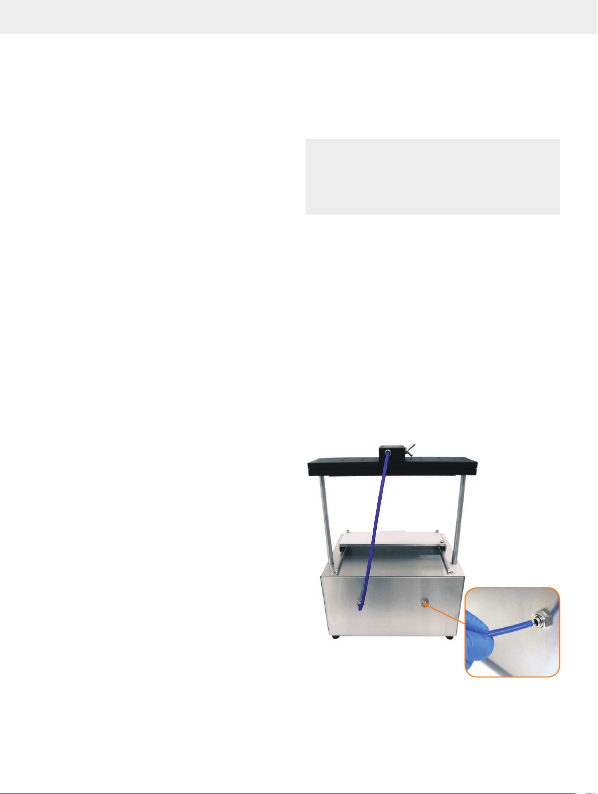
The unit will already have the tubing attached in the back as
shown in Figure 1.
1. Open the inner box and remove the smaller boxes. These
contain the gas supply installation kit, sealing gasket, etc;
check the contents against the packing list on the next page.
2. Gently pull the unit from the box and set the unit on a bench
or in a fume hood. See the site requirements above.
3. Using the supplied gas supply installation kit (PPM-GA),
plumb the back of the unit to the gas supply (see Figure1).
Refer to the Gas Source section above for gas requirements.
4. Position the unit so that the handle and gauges are facing
forward and the gas supply is in the rear. Note that the unit
weighs 14 kg (31 lbs).
There are a variety of filters available for the removal of
moisture, particulates, and hydrocarbons most commonly found
within house gas supply systems. The optimum gas supply
(80 psi) is achieved by a regulator positioned between the gas
source and the unit. The supplied gas supply installation kit
(PPM-GA) provides the par ts necessary to make the connection
between the gas regulator and the unit.
Minimum pressure 60 psi (4.1 bar)
Maximum pressure 100 psi (6.9 bar)
Optimum pressure 80 psi (5.5 bar)
Figure 1. Connec t the gas line to the right port at t he back of the unit.
Biotage® PRESSURE+ 48 User Manual | © Biotage 2017
Page 5

Packing List
PRESSURE+ 48 is shipped with the following items:
Part Number Description Qty
PPM-A48-GSKT PRESSURE+ 48 Sealing Gasket 48
positions (also contains a hex key)
1
Installation
PPM-GA PRESSURE+ Gas Supply Adaptor for
PPM-A48WSTRCK
4132 47 User Manual 1
all models (6’ of 1/8” i.d. polyethylene
tubing and 1/8” and 1/4” NPT
connectors)
PRESSURE + 48 Waste Bin Rack with
Insert s (3)
1
1
Column Racks and Collection Racks
Note: Column racks and collection racks must be purchased
separately; see the list of racks below.
Part Number Description
PPM-A48-1RCK PRESSUR E+ 48 SPE Column Rack 1 mL
PPM-A48-3RCK PR ESSURE+ 48 SPE Column Rack 3 mL
PPM-A48-6RCK PRESSURE+ 48 SPE Column Rack 6 mL
PPM-A48-1275 PRESSURE+ 48 Collection Rack 12 x 75 mm
PPM-A48-13100 PRESSURE+ 48 Collection Rack 13 x 100 mm
PPM-A48-16100 PRESSURE+ 48 Collection Rack 16 x 100 mm
PPM-A48-1232 PRESSURE+ 48 Sample Vial Rack 12 x 32 mm
Page 6
System Description
System Description
PRESSURE+ 48 is a positive pressure manifold designed to
process SPE columns using a pressurized gas source.
Load the Columns
PRESSURE+ 48 units are compatible with all commonly
used 1 mL, 3 mL and 6 mL tabless columns used for sample
preparation.
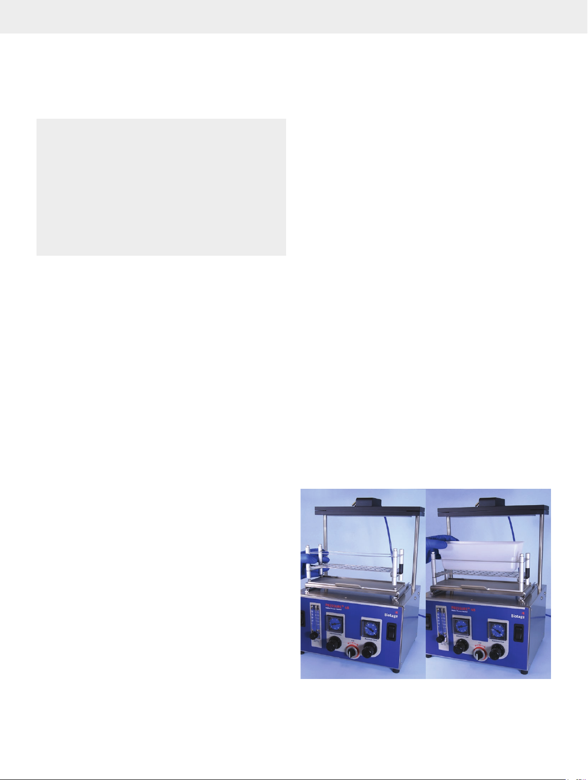
The handgrip on the front of the platform helps you to slide
the platform with the racks forward and backward under the
manifold. Stack the column rack onto the waste bin rack and
populate with the required number of columns. Each column will
be pressurized equally even if columns are omitted.
Push the platform and populated rack assembly to the back
of the track until it reaches the stop point (under the upper
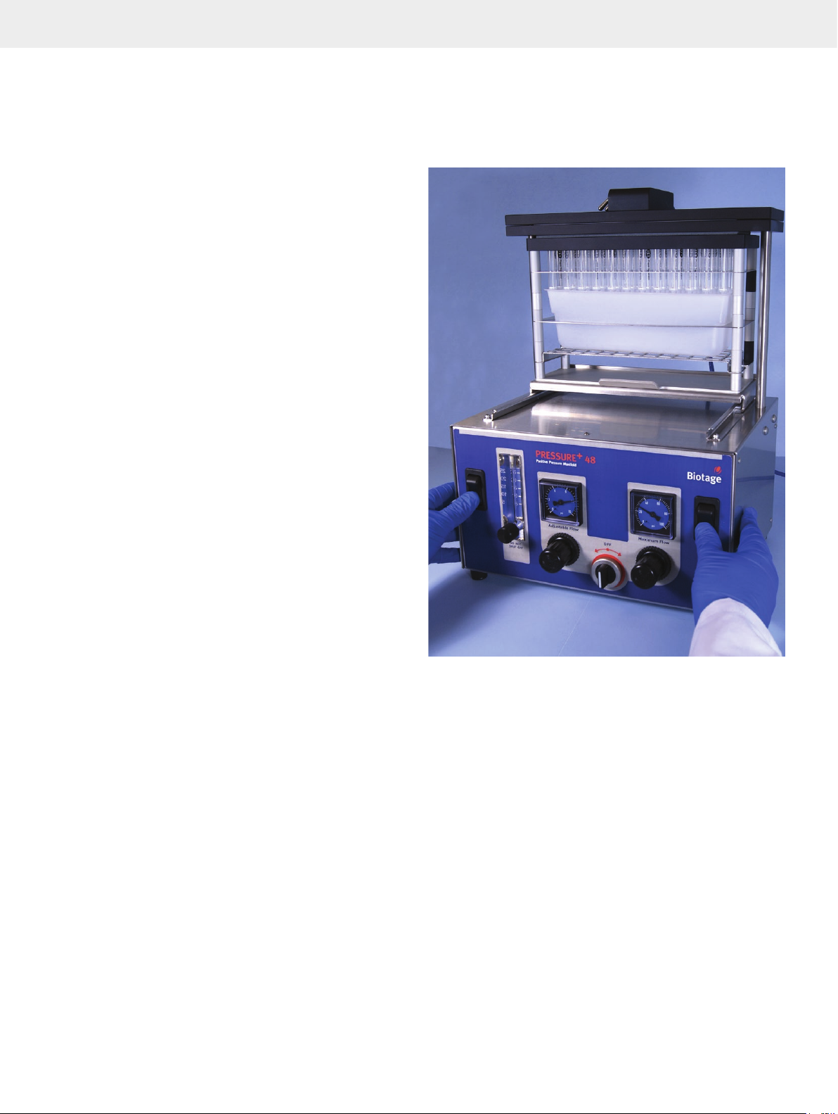
manifold). To lower the manifold, press down on the two rocker
switches simultaneously and hold for approximately 3 seconds.
This will activate the upper manifold and it will self-adjust to
an appropriate height by lowering and compressing. If you let
go too soon, the upper manifold will rise up and you can simply
repeat by pressing down on the rocker switches and holding
them again for approximately 3 seconds.
To release the column rack, press up on both rocker switches,
then slide the assembly forward.
Note: The upper manifold is powered by the gas source and the
speed is preset and not adjustable.
IMPO RTANT: An important safety feature of the unit is the
requirement to hold both rocker switches for approximately
3 seconds simultaneously to lower the manifold. This is to keep
hands clear of moving parts during compression.
Figure 2 . Lower the manifold by pressing down on the t wo rocker switches
simultaneously for approximately 3 seconds.
Biotage® PRESSURE+ 48 User Manual | © Biotage 2017
Page 7
Flow Control
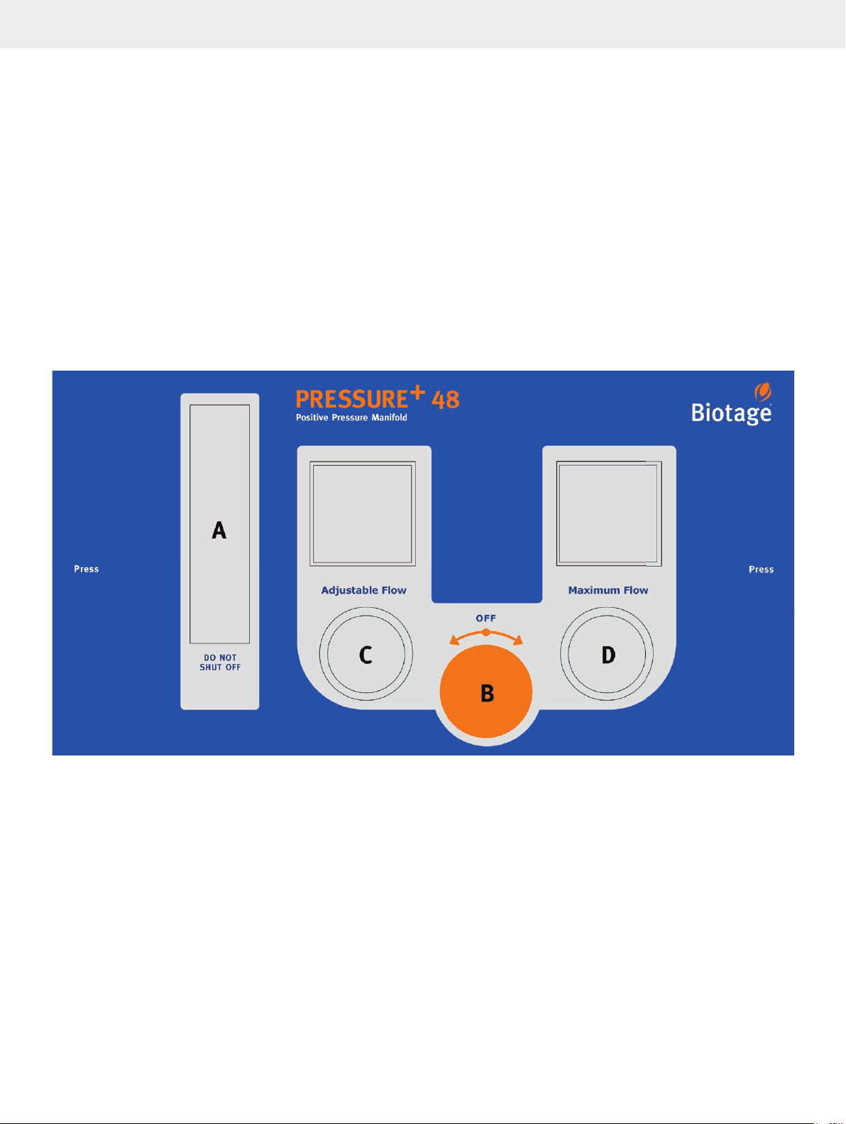
The PRESSURE+ 48 unit has a two-tier gas delivery system. The
flow control switch (B) enables setting and operation of gas
flow in addition to turning gas flow on and off:
»
Adjustable Flow Rate (0 to 15 psi, 0 to 1180 mL/min)
Recommended for sample loading and elution. By turning
the flow control switch (B) to the lef t to the Adjustable Flow
position, gas is channeled through the Adjustable Flow
regulator (C) and then through a rotometer (A) controlled by
the needle valve positioned at its base. This path through
the rotometer provides ver y precise and slow flow through
the columns by limiting gas flow from 0 to 1180 mL/min.
IMPO RTANT: As indicated on the label, never turn the
rotometer completely off. Seating the needle valve into its
orifice can damage the unit.
System Description
»
Maximum Flow Rate (0 to 100 psi)
Recommended for column washing, dr ying, etc. By
turning the flow control switch (B) to the right to the
Maximum Flow position, gas is introduced at the pressure
set on the Maximum Flow regulator (D). The pressure
range for this regulator is 0 to 100 psi and should be
used when processing very viscous or dir ty samples.
»
Turn Off the Gas
By turning the flow control switch (B) to the OFF
position, no gas will flow through the manifold.
IMPO RTANT: The unit should always be in the OFF position
during compression and decompression cycles and when
not in use. Always shut off the external gas supply when the
unit is not in use.
Figure 3. The rotometer (A), flow control switch (B), Adjustable Flow regulator (C), and Maximum Flow regulator (D).
Page 8
Operation
Operation
Warning
• Keep hands, loose clothing, and long hair away from the
manifold when it is moving.
• Only use racks and waste bin inserts supplied by Biotage and
ensure to stack the racks properly on the platform to avoid
spillage. The racks are physically keyed to the platform by three
elevated pins on the platform that recess into the bottom of the
rack. When installed properly, the rack should sit level on the
platform.
• To prevent personal injury and/or equipment damage, always
use impermeable gloves, chemical safety goggles and protective
clothing, follow all generally-accepted lab safet y procedures and
applicable laws and regulations, and consult your company’s
safet y exper t for guidance.
Step-by-Step Instructions
1. Ensure the unit is connected to a gas supply; see Installation
section on page 2.
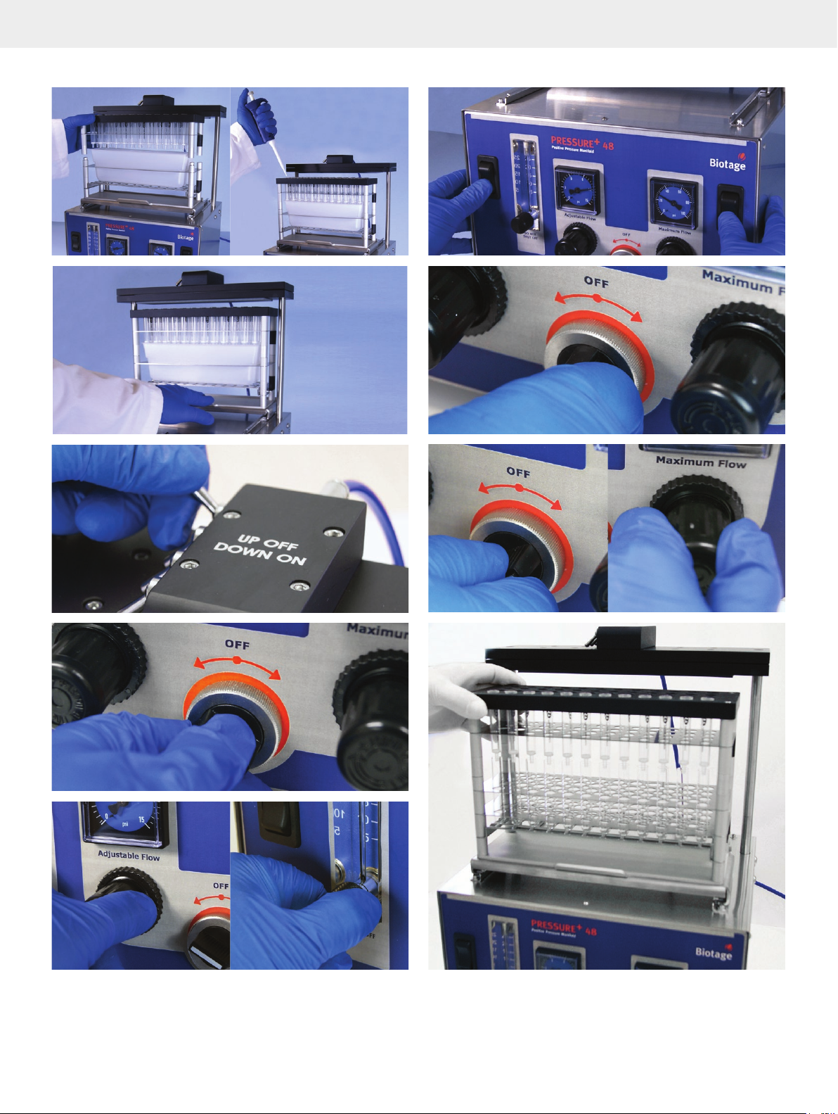
2. Place a waste bin rack and a waste bin insert on the
platform; see Figure A.
3. Insert desired number of columns in a column rack. Each
column will be pressurized equally even if columns are
omitted.
4. Place the column rack on top of the waste bin rack and add
sample; see Figure B.
5. Slide the platform back to position the column rack under
the manifold; see Figure C.
6. Turn on the gas for the rows in use, i.e. toggle the
appropriate gas switch(es) on top of the manifold to the ON
position. There are four switches; one switch for each row of
columns. See Figure D.
7. Turn the flow control switch to the left to the Adjustable Flow
position; see Figure E.
8. Adjust the regulator and rotometer to achieve the desired
flow rate; see Figure F.
IMPO RTANT: As indicated on the label, never turn the
rotometer completely off. Seating the needle valve into its
orifice can damage the unit.
13. Add wash solvent to each column and slide the platform
back to position the column rack under the manifold.
14. Lower the manifold by pressing down on the two rocker
switches simultaneously for approximately 3 seconds.
15. Turn the flow control switch to the left to the Adjustable Flow
position; see Figure E.
16. Turn the flow control switch to the right to the Maximum
Flow position and adjust the manifold pressure to the
desired setting for the drying period; see Figure I.
17. When the drying period is completed, turn the flow control
switch to the OFF position. See Figure H.
18. Raise the manifold by pressing up on the two rocker
switches simultaneously.
19. Pull out the platform and replace the waste bin rack with a
collection rack; see Figure J.
20. Add elution solvent to each column.
21. Allow the samples to elute by gravity or repeat step 5
through 12 for pressure assisted elution. Tip: To trigger
gravity elution, slide the platform back to position the
rack under the manifold, ensure the flow control switch is
in the OFF position and then lower the manifold. Raise the
manifold after a few seconds.
IMPO RTANT: The unit should always be in the OFF position
during compression and decompression cycles and when not in
use. Always shut off the external gas supply when the unit is not
in use.
A
9. Lower the manifold by pressing down on the two rocker
switches simultaneously for approximately 3 seconds; see
Figure G.
10. When all liquids have passed through the columns, turn the
flow control switch to the OFF position. See Figure H.
11. Raise the pressure manifold by pressing up on the two
rocker switches simultaneously.
12. Pull out the platform.
Biotage® PRESSURE+ 48 User Manual | © Biotage 2017
Page 9
Operation
B
C
D
G
H
I
E
F
J
Page 10

Maintenance
Maintenance
Replace the Sealing Gasket
You need a sealing gasket with 48 positions and a hex key
(PPM-A48-GSKT). In order to maintain compliance, only sealing
gaskets supplied by Biotage must be used with the unit.
1. Shut off the external gas supply.
2. Ensure that at least one gas switch on top of the manifold is
in the ON position.
3. Turn the unit’s flow control switch to the right to the
Maximum Flow position.
4. When there is no remaining pressure in the unit (0 psi), turn
the unit’s flow control switch to the OFF position.
5. Remove the two 1/4-20 hex screws that hold the upper
manifold to the unit (standoffs) using the hex key.
6. Lift the manifold off the standoffs and place it upside down
on the benchtop.
7. Remove the old sealing gasket from the manifold and clean
the manifold using ethanol.
8. Remove the backing of the replacement sealing gasket.
9. Align the holes on the new sealing gasket with the
manifold’s holes and adhere the seal.
10. Fasten the manifold (with the sealing gasket facing down) to
the standoffs using the two hex screws and the hex key.
Note: The adhesive on the sealing gaskets is volatile and
cannot be stored for long periods of time at room temperature.
For extended storage, place sealing gaskets in refrigerated
conditions at 2°C to 5°C
(35.6°F to 41°F).
Clean
Materials of construction are primarily stainless steel and
anodized aluminum. Other materials include silicone rubber,
polyethylene, and polypropylene. Always clean up spills or
overflow immediately.
»
If you wish to clean the sealing gasket, use a soft cloth,
dampened with ethanol or methanol. The sealing
gasket is manufactured from silicone rubber.
»
To clean the manifold, use a soft cloth, dampened with
water. Never spray or apply water directly to the manifold.
Note: The controls and gauges are not solvent resistant.
Biotage® PRESSURE+ 48 User Manual | © Biotage 2017
Page 11

General Information
General Information
Consumables and Accessories
To order consumables and accessories, see contact information on
the back of this document or visit our website www.biotage.com.
Part Number Description Qty
PPM-A48-1RCK SPE Column Rack 1 mL 1
PPM-A48-3RCK SPE Column Rack 3 mL 1
PPM-A48-6RCK SPE Column Rack 6 mL 1
PPM-A48-1275 Collection Rack 12 x 75 mm 1
PPM-A48-13100 Collection Rack 13 x 100 mm 1
PPM-A48-16100 Collection Rack 16 x 100 mm 1
PPM-A48-1232 Sample Vial Rack 12 x 32 mm 1
C44651 12 x 75 mm Test Tube, Uncapped 1000
C40707 13 x 100 mm Test Tube, Uncapped 1000
C40708 16 x 100 mm Test Tube, Uncapped 1000
PPM-A48-WST Waste Bin Inserts 3
PPM-A48-WSTRCK Waste Bin Rack with Inserts (3) 1
Contact Us
Biotage Sweden AB
Box 8
SE-751 03 Uppsala
SWEDEN
Visiting address: Vimpelgatan 5
Phone: +46 18 56 59 00
Fax: +46 18 59 19 22
E-mail: [email protected]
Website: www.biotage.com
Please contact your local Biotage representative. See contact
information on the back of this document or visit our website
www.biotage.com.
PPM-A48-GSKT Sealing Gasket 48 positions (also
contains a hex key)
PPM-GA PRESSURE+ Gas Supply Adaptor for
all models (6' of 1/8" i.d. polyethylene
tubing and 1/8" and 1/4" NPT
connectors)
1
1
For a complete list, please visit our website www.biotage.com.
Manufacturer
Made in USA
for Biotage Sweden AB
Page 12

Your Complete
Partner for Effective
Chemistry
Biotage is a worldwide supplier of
instruments and accessories designed
to facilitate the work of laboratory and
process chemists. With our deep knowledge
of the industry, academic contacts and
in-house R&D teams, we can deliver the best
solutions to your challenges. We take great
pride in our flexibility and ability to meet our
customer’s individual needs. With strong
foundations in both analytical, organic and
process chemistry, we can offer the widest
range of solutions available on the market.
Title Truncated if Neccessar y... | Page
EUROPE
Main Of fice: +46 18 565900
Toll Free: +800 18 565710
Fax: +46 18 591922
Order Tel: +46 18 565710
Order Fa x: +46 18 565705
Suppor t Tel: +46 18 56 59 11
Suppor t Fax: + 46 18 56 57 11
Part Numb er: 413247-C
© 2017 Biotage. A ll rights r eserve d. No materi al may be repr oduced or p ublished w ithout the wr itten p ermissi on of Biotag e.
Informa tion in this d ocument is s ubject to c hange with out notice a nd does not r eprese nt any commit ment from B iotage. E&O E.
A list of all t rademar ks owned by Bi otage AB is ava ilable at ww w.biotage.c om/legal. O ther pro duct and co mpany names me ntioned
herein m ay be tradem arks or re gistere d tradema rks and/or se rvice ma rks of thei r respec tive owner s, and are us ed only for
explana tion and to th e owners’ b enefit, wi thout inte nt to infrin ge.
© Biotage 2017
NORTH & LATIN AMERICA
Main Of fice: +1 704 654 4900
Toll Free: +1 800 446 4752
Fax: +1 704 654 4917
Order Tel: +1 704 654 4900
Order Fa x: +1 434 296 8217
Suppor t Tel: +1 800 446 4752
Outside US: +1 704 654 4900
JAPAN
Tel: +81 3 5627 3123
Fax: +81 3 5627 3121
CHINA
Tel: +86 21 2898 6655
Fax: +86 21 2898 6153
KOREA
Tel: + 82 31 706 8500
Fax:+ 82 31 706 8510
Distr ibutors in other regions
are listed on ww w.biotage.com
 Loading...