

Page 1

Viotech 3100+ Setup Manual
FCC Information and Copyright
This equipment has been tested and found to comply with the limits of a Class
B digital device, pursuant to Part 15 of the FCC Rules. These limits are designed
to provide reasonable protection against harmful interference in a residential
installation. This equipment ge nerates, uses, and can radiate radio frequency
energy and, if not i nstalled and used in accordance with the instructions, may
cause harmful interference to radio communications. There is no guarantee
that interference will not occur in a particular installation.
The vendor makes no representations or warranties with respect to the
contents here and specially disclaims any implied warranties of merchantability
or fitness for any purpose. Further the vendor reserves the right to revise this
publication and to make changes to the contents here without obligation to
notify any party beforehand.
Duplication of this publication, in part or in whole, is not allowed without first
obtaining the vendor’s approval in writing.
The content of this user’s manual is subject to be changed without notice and
we will not be responsible for any mistakes found in this user’s manual. All the
brand and product names are trademarks of their respective companies.
Page 2

Table of Contents
Chapter 1: Introduction ........................................ 1
1.1 Before You Start ................................................................................ 1
1.2 Package Checklist............................................................................. 1
1.3 Motherboard Features...................................................................... 2
1.4 Rear Panel Connectors ..................................................................... 3
1.5 Motherboard Layout......................................................................... 4
Chapter 2: Hardware Installation .......................... 5
2.1 Installing Central Processing Unit (CPU)....................................... 5
2.2 FAN Headers...................................................................................... 5
2.3 Installing System Memory................................................................ 6
2.4 Connectors and Slots......................................................................... 8
Chapter 3: Headers & Jumpers Setup .................. 11
3.1 How to Setup Jumpers .................................................................... 11
3.2 Detail Settings.................................................................................. 11
Chapter 4: RAID Functions .................................. 15
4.1 Operating System............................................................................ 15
4.2 Raid Arrays...................................................................................... 15
4.3 How RAID Works............................................................................. 15
Chapter 5: Useful Help ........................................ 17
5.1 Driver Installation Note.................................................................. 17
5.2 AMI BIOS Beep Code....................................................................... 18
5.3 Extra Information............................................................................ 19
5.4 Troubleshooting............................................................................... 20
Appendix: SPEC In Other Languages ................... 22
German.................................................................................................................. 22
French .................................................................................................................... 24
Italian..................................................................................................................... 26
Spanish ................................................................................................................... 28
Portugue se ............................................................................................................ 30
Polish...................................................................................................................... 32
Russian ................................................................................................................... 34
Arabic..................................................................................................................... 36
Japanese ................................................................................................................ 38
Page 3
CHAPTER 1: INTRODUCTION
Viotech 3100+
1.1 B
EFORE YOU START
Thank you for choosing our product. Before you start installing the
motherboard, please make sure you follow the instructions below:
Prepare a dry and stable working environment with
sufficient lighting.
Always disconnect the computer from power outlet
before operation.
Before you take the motherboard out from anti-static
bag, ground yourself properly by touching any safely
grounded appliance, or use grounded wrist strap to
remove the static charge.
Avoid touching the components on motherboard or the
rear side of the board unless necessary. Hold the board
on the edge, do not try to bend or flex the board.
Do not leave any unfastened small parts inside the
case after installation. Loose parts will cause short
circuits which may damage the equipment.
Keep the computer from dangerous area, such as heat
source, humid air and water.
The operating temperatures of the computer should be
0 to 45 degrees Celsius.
1.2 PACKAGE CHECKLIST
HDD Cable X 1 (optional)
Rear I/O Panel for ATX Case X 1
Installation Guide X 1
Fully Setup Driver CD X 1 (full version manual files inside)
Serial ATA Cable X 2
Serial ATA Power Cable X 1 (optional)
USB 2.0 Cable X1 (optional)
Note: The package contents may be different due to area or your motherboard version.
1
Page 4
Motherboard Manual
1.3 MOTHERBOARD FEATURES
SPEC
NanoBGA2
CPU
FSB VIA V4 BUS 800MHz
Chipset
Graphics Chrome9 HC GFX Max Shared Video Memory is 64/128/256MB
Super I/O
Main
Memory
IDE Int egrat ed ID E Co ntro l le r
SATA Integrated Serial ATA Controller
LAN VIA VT6113 10 / 100 Mb/s auto negotiation
Sound
Codec
Slot
On Board
Connector
VIA CPU On-board
VIA C7-D 1.8G CPU
VIA CN896
VIA VT8237S
ITE 8712F
Prov ides the most commonly used leg acy
Super I/O functionality.
Low Pin Count Interface
DIMM Slots x 2
Each DIMM supports 256MB/512MB/1GB
DDR2
Max Memory Capacity 2GB
Supports DDR2 533 / 667
VIA VT1708B
PCI slot x1 Supports PCI expansion card
PCI Express x 16 slot x1
IDE Conn ector x1 Each connector suppo rts 2 IDE device
Floppy Connector x1 Each connector supports 2 Floppy drives
SATA Connector x2 Each conne ctor supports 1 SATA devices
Front Panel Connector x1 Supports front panel facilities
Front Audio Connector x1 Supports front panel audio function
S/PDIF out Connector x1 Supports digital audio out function
2
Supports Hyper-Threading
Execute Disab le B it
Extended Memory 64 Technology
En v ironm ent C o ntro l in iti at i ves,
H/W Mon ito r
Fan Sp eed Contro ller
ITE's "S mart Guardian " funct ion
Sin g le Channe l Mo de DDR2 m e mo r y modu le
Register ed DIMM and ECC D IMM is no t supported
Ultra DMA 33 / 66 / 100 / 133 Bus Master Mode
supports PIO Mode 0~4,
Data transfer rates up to 3.0 Gb/s.
SATA Vers io n 2.0 specif ic at io n co mpliant.
5.1 channels audio out
High-Definition Audio support
Supports PCI-E x16 expansion card
Page 5
SPEC
CPU Fan Header x1 CPU Fan power supply
System Fan Header x1 System Fan Power supply
Clear CMOS Head er x1 Restore CMOS data to facto ry default
USB Connector x2 Each conne ctor s upports 2 front panel USB port s
Power Connector (24pin) x1 Connects to Power supply
PS/2 Keyboard x1
PS/2 Mous e x1
Serial Port x1
Back Panel
I/O
Board Size 180 (W) x 223 (L) mm
Special
Features
OS Support Windows XP / Vista / 7
Printer Port x1
VGA port x1
LAN port x1
USB Port x 4
Audio Jack x3
RAID 0 / 1
Viotech 3100+
Connects to PS/2 Keyboard
Connects to PS/2 Mouse
Provide RS-232 Serial connection
Provide 1 connection for printer
Connects to monitor.
Connects to RJ-45 et hernet c ab le
Connects to USB devices
Provide Audio-In/Out and microphone connection
Biostar reserves the r ight to add or remove support
for any OS with or without notice.
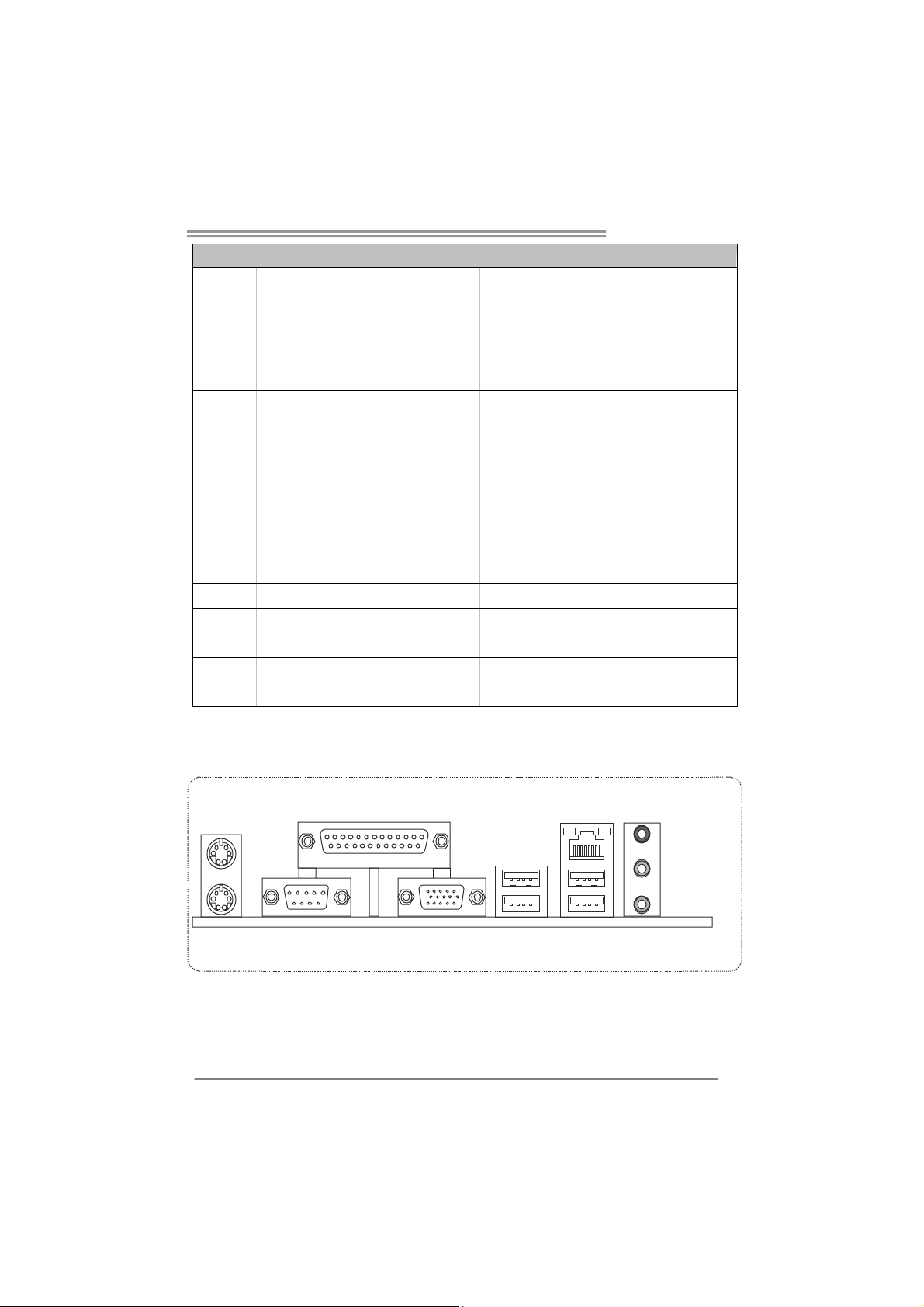
1.4 REAR PANEL CONNECTORS
PS/2
Mouse
PS/2
COM Port
Keyboard
Since the audio chip supports High Definition Audio Specification, the function of each audio
jack can be defined by software. The input / output function of each audio jack listed above
represents the default setting. However, when connecting external microphone to the audio
port, please use the Line In (Blue) and Mic In (Pink) audio jack.
Print er Port
VGA
LAN
USBX2USBX2
Line In/
Surrou nd
Line Out
Mic In 1/
Bass/ Center
3
Page 6
Motherboard Manual
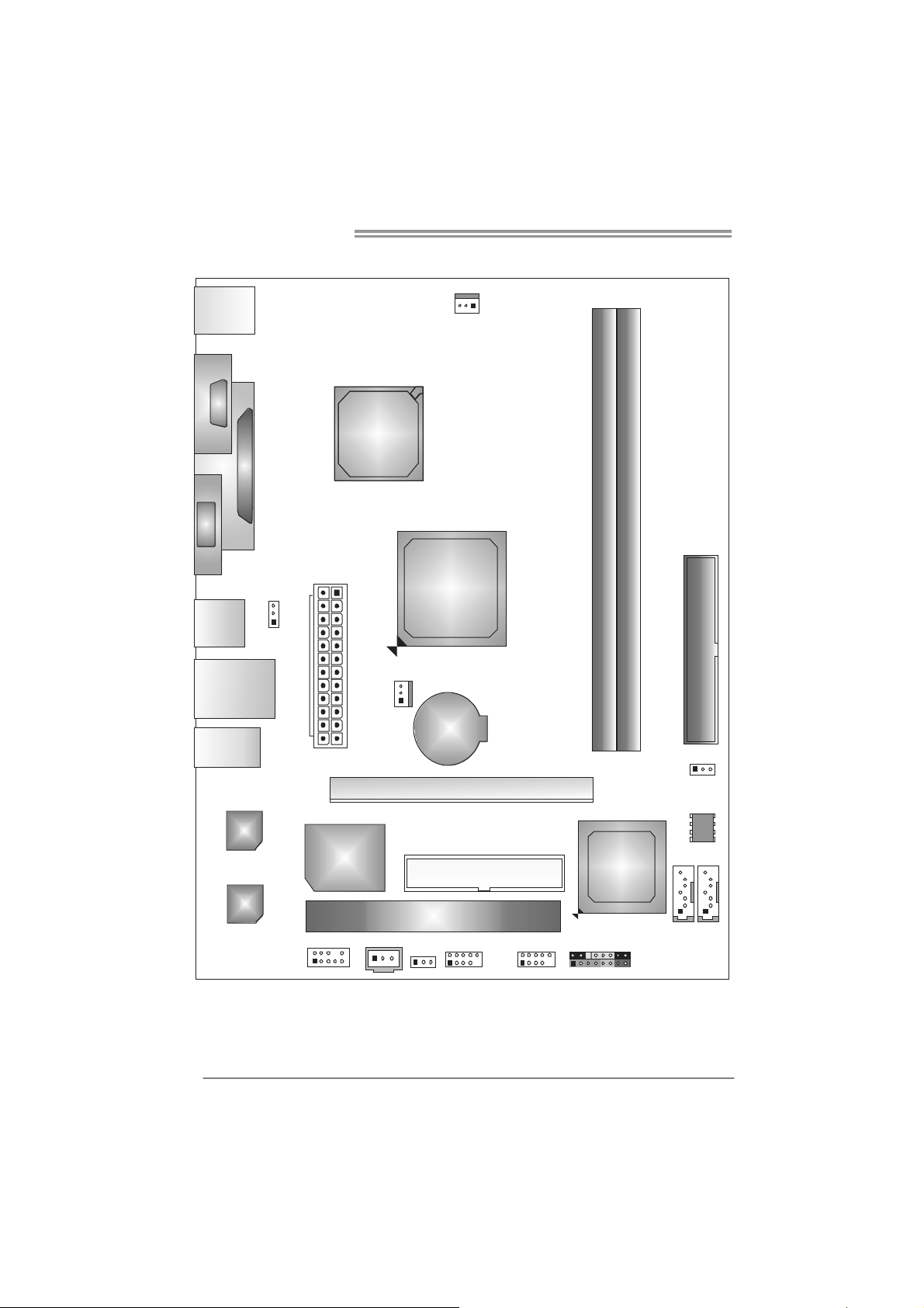
1.5 MOTHERBOARD LAYOUT
KBMS1
C
O
C
M
O
1
M
1
VGA 1
USB1
RJ4 5USB1
AUDIO1
PRINT1
JUSBV1
AT X P W R 1
VIA
Nano
BGA2
CPU1
SYS_FAN1
CPU_FAN1
VIA
CN896
BAT1
DIMMA1
DIMMA2
IDE1
LAN
Super
I/O
Codec
F_AUD IO1
JSPDIFOUT1
Note: ■ represents the 1st pin.
4
PCI1
JUSBV2
PEX16_1
FDD1
F_USB1
F_USB2
VIA
VT8237S
PANEL1
JCMOS1
BIOS
SATA2
SATA1
Page 7
CHAPTER 2: HARDWARE INSTALLATION
Viotech 3100+
2.1 I
NSTALLING CENTRAL PROCESSING UNIT (CPU)
The motherboard includes an embedded VIA C7-D 1.8G processor, and a
heatsink has been installed to provide sufficient cooling.
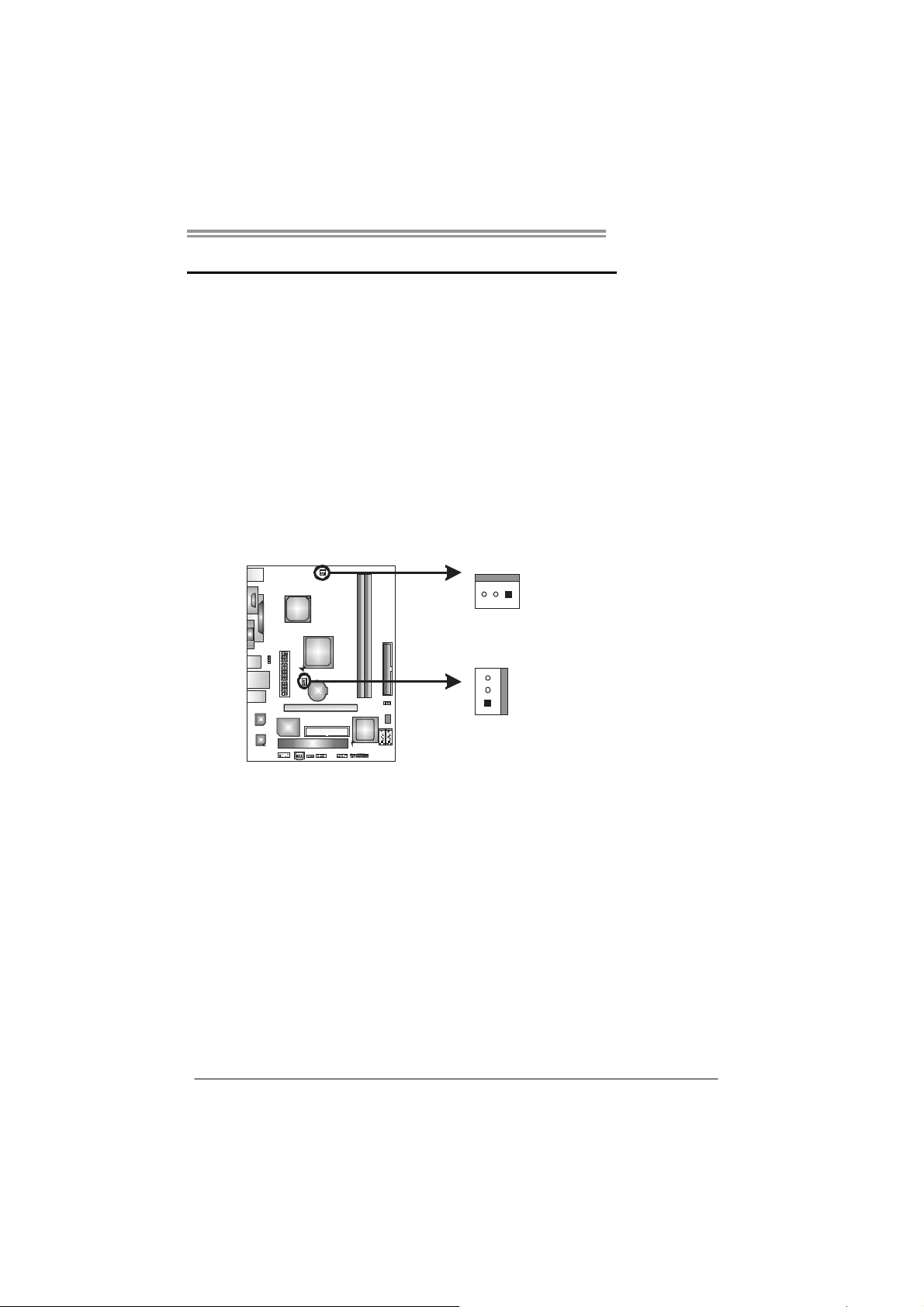
2.2 FAN HEADERS
These fan headers support cooling-fans built in the computer. The fan
cable and connector may be different according to the fan manufacturer.
Connect the fan cable to the connector while matching the black wire to
pin#1.
CPU_FAN1: CPU Fan Header
SYS_FAN1: System Fan Header
31
CPU_FAN1
3
1
SYS_FAN1
Pin
Assignment
1 Ground
2 +12V
3 FAN RPM rate
sense
Note:
CPU_FAN1/SYS_FAN1 support 3-pin head connector. When connecting with wires onto
connectors, please note that the red wire is the positive and should be co nnected to
pin#2, and the black wire is Ground and should be connected to GND.
5
Page 8

Motherboard Manual
2.3 INSTALLING SYSTEM MEMORY
A. DDR2 Module
DIMMA1
DIMMA2
1. Unlock a DIMM slot by pressing the retaining clips outward. Align a
DIMM on the slot such that the notch on the DIMM matches the
break on the Slot.
2. Insert the DIMM vertically and firmly into the slot until the retaining
chip snap back in place and the DIMM is properly seated.
6
Page 9
B. Memory Capacity
DIMM Socket
Location
DIMMA1 256MB/512MB/1GB
DIMMA2 256MB/512MB/1GB
DDR2 Module
Viotech 3100+
Total Me m ory
Size
Max is 2GB.
7
Page 10
Motherboard Manual
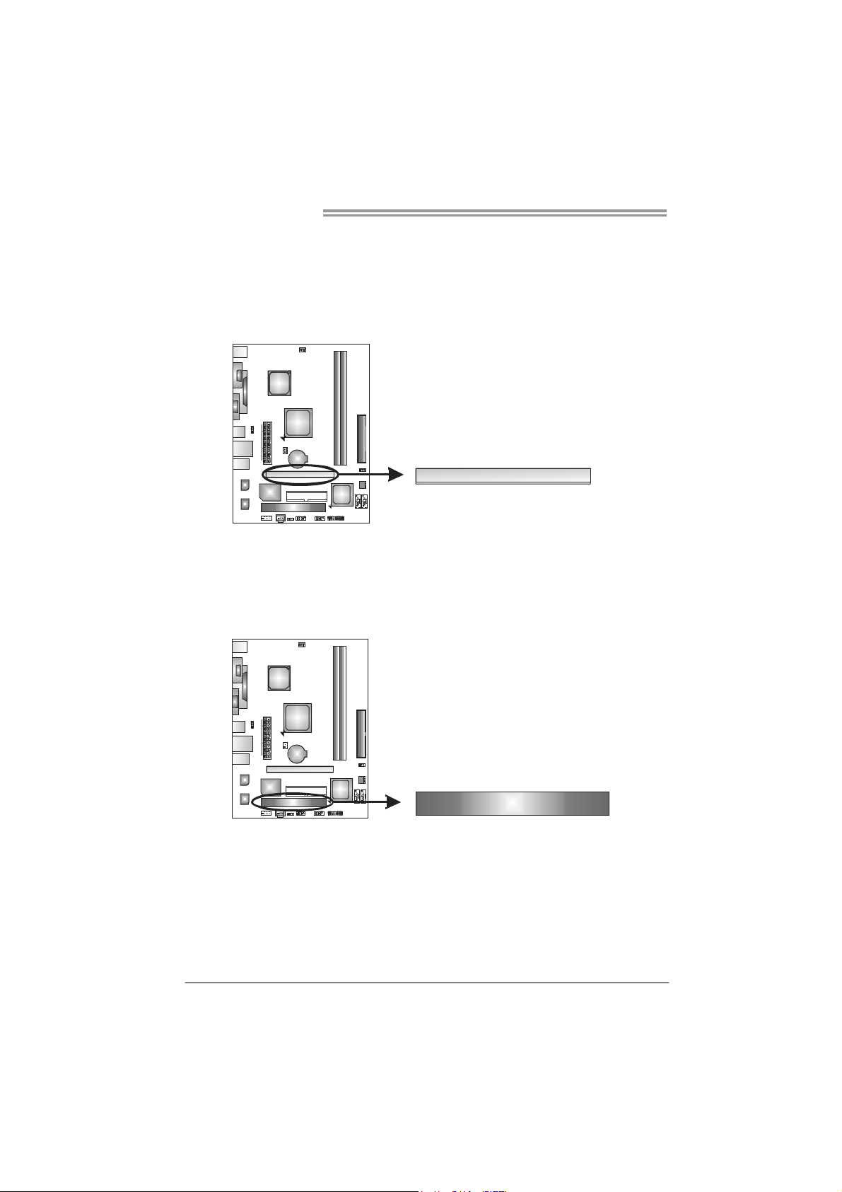
2.4 CONNECTORS AND SLOTS
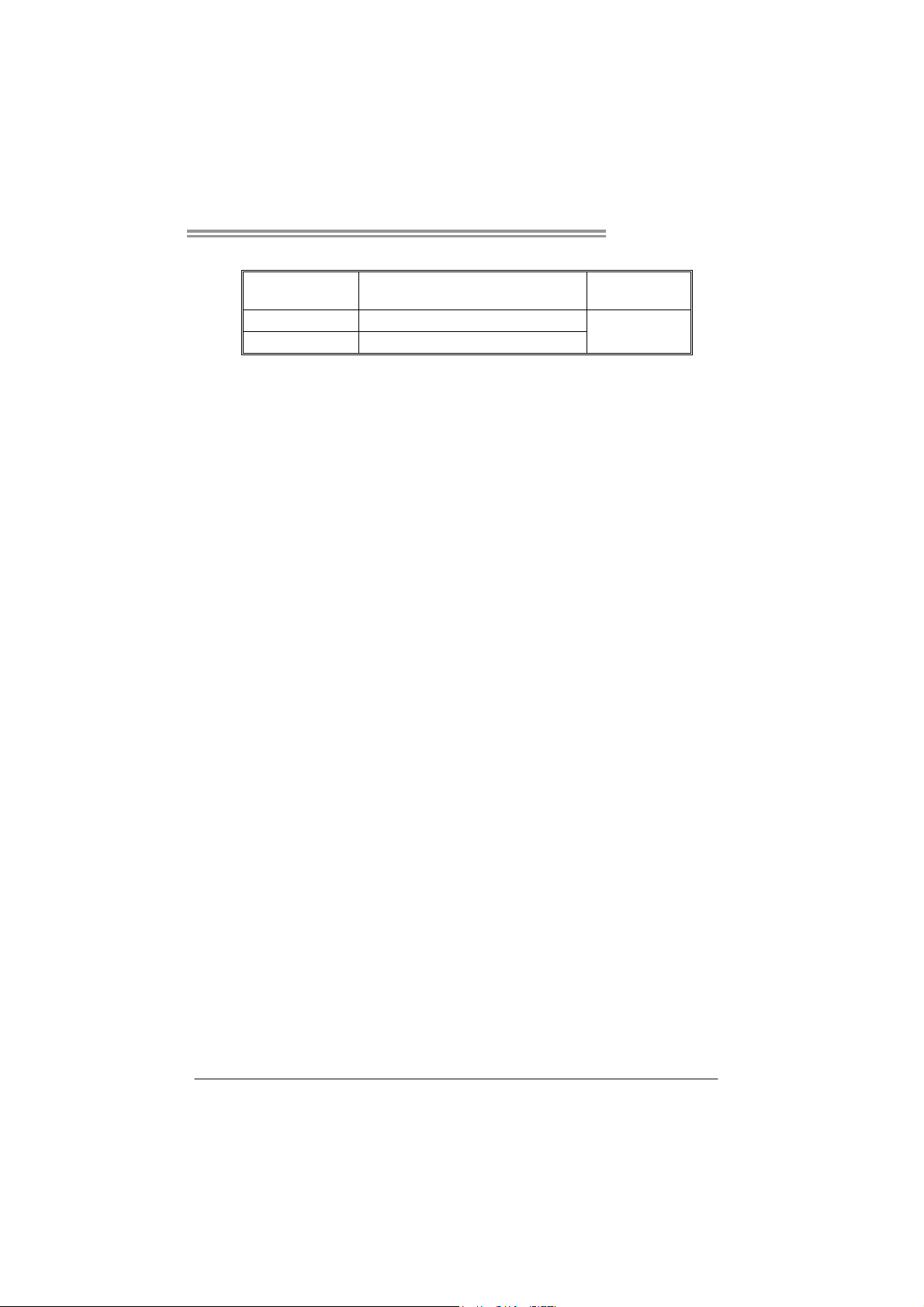
FDD1: Floppy Disk Connector
The motherboard provides a standard floppy disk connector that supports 360K,
720K, 1.2M, 1.44M and 2.88M floppy disk types. This connector supports the
provided floppy drive ribbon cables.
2
34
331
IDE1: Hard Disk Connector
The motherboard has a 32-bit Enhanced PCI IDE Controller that provides PIO
Mode 0~4, Bus Master, and Ultra DMA 33/66/100 functionality.
The IDE connector can connect a master and a slave drive, so you can connect
up to two hard disk drives.
40
39
21
8
Page 11
Viotech 3100+
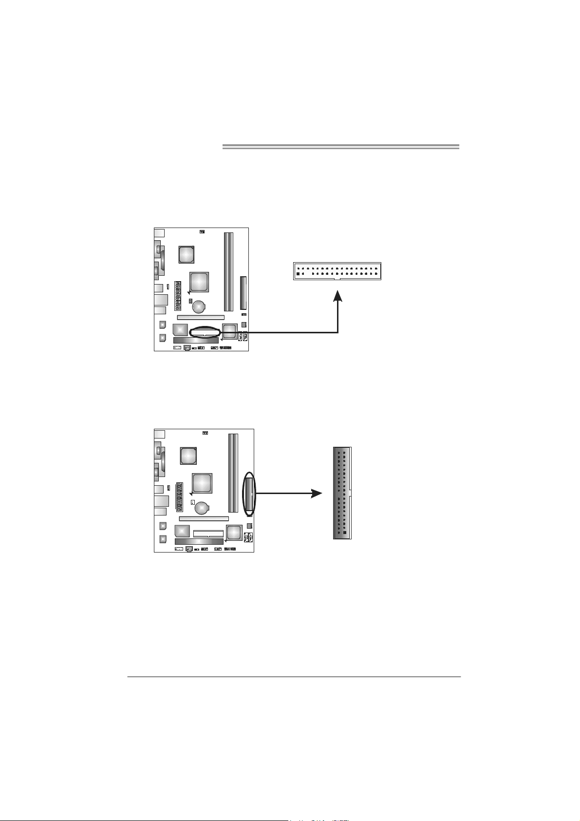
SATA1/SATA2: Serial ATA Connectors
The motherboard has a PCI to SATA Controller with 2 channels SATA interface,
it satisfies the SATA 2.0 spec and with transfer rate of 3Gb/s.
Pin Assignment
1 Ground
2 TX+
SATA2
SATA1
7
4
1
3 TX-
4 Ground
5 RX-
6 RX+
7 Ground
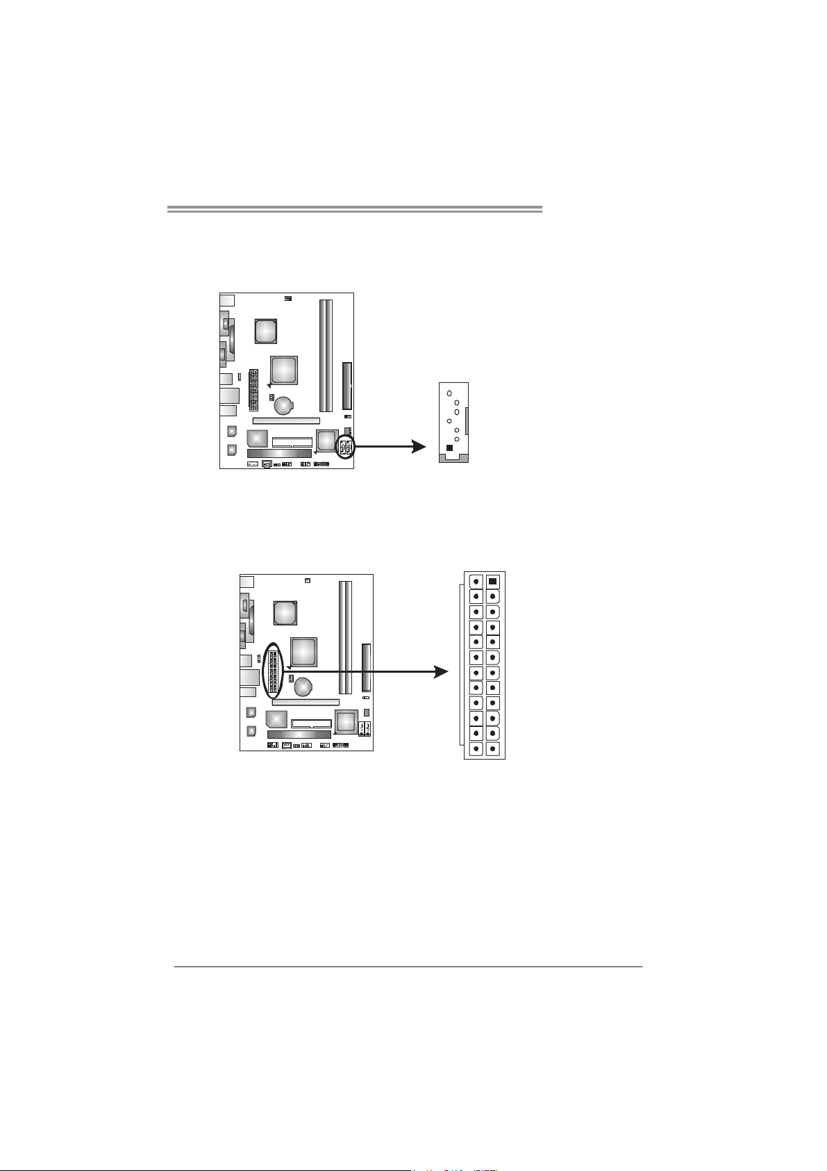
ATXP W R1: AT X P ower Source Connector
This connector allows user to connect 24-pin power connector on the ATX
power supply.
13
24
Pin Assignment Pin Assignment
13 +3.3V 1 +3.3V
14 -12V 2 +3.3V
15 Gro und 3 Gro und
16 PS_ON 4 +5V
17 Gro und 5 Gro und
18 Ground 6 +5V
19 Gro und 7 Gro und
20 NC 8 PW_OK
21 +5V 9 Standby Voltage+5V
22 +5V 10 +12V
23 +5V 11 +12V
24 Ground 12 +3.3V
1
12
9
Page 12
Motherboard Manual
PEX16_1: PCI-Express x16 Slot
- PCI-Express 1.0a compliant.
- Maximum theoretical realized bandwidth of 4GB/s simultaneously per
direction, for an aggregate of 8GB/s totally.
PCI1: Peripheral Component Interconnect Slot
The motherboard is equipped with 1 standard PCI slot. PCI stands for Peripheral
Component Interconnect, and it is a bus standard for expansion cards. This PCI
slot is designated as 32 bits.
PEX16_1
10
PCI1
Page 13
Viotech 3100+
CHAPTER 3: HEADERS & JUMPERS SETUP
3.1 H
OW TO SETUP JUMPERS
The illustration shows how to set up jumpers. When the jumper cap is
placed on pins, the jumper is “close”, if not, that means the jumper is
“open”.
Pin opened Pin closed Pin1-2 closed
3.2 DETAIL SETTINGS
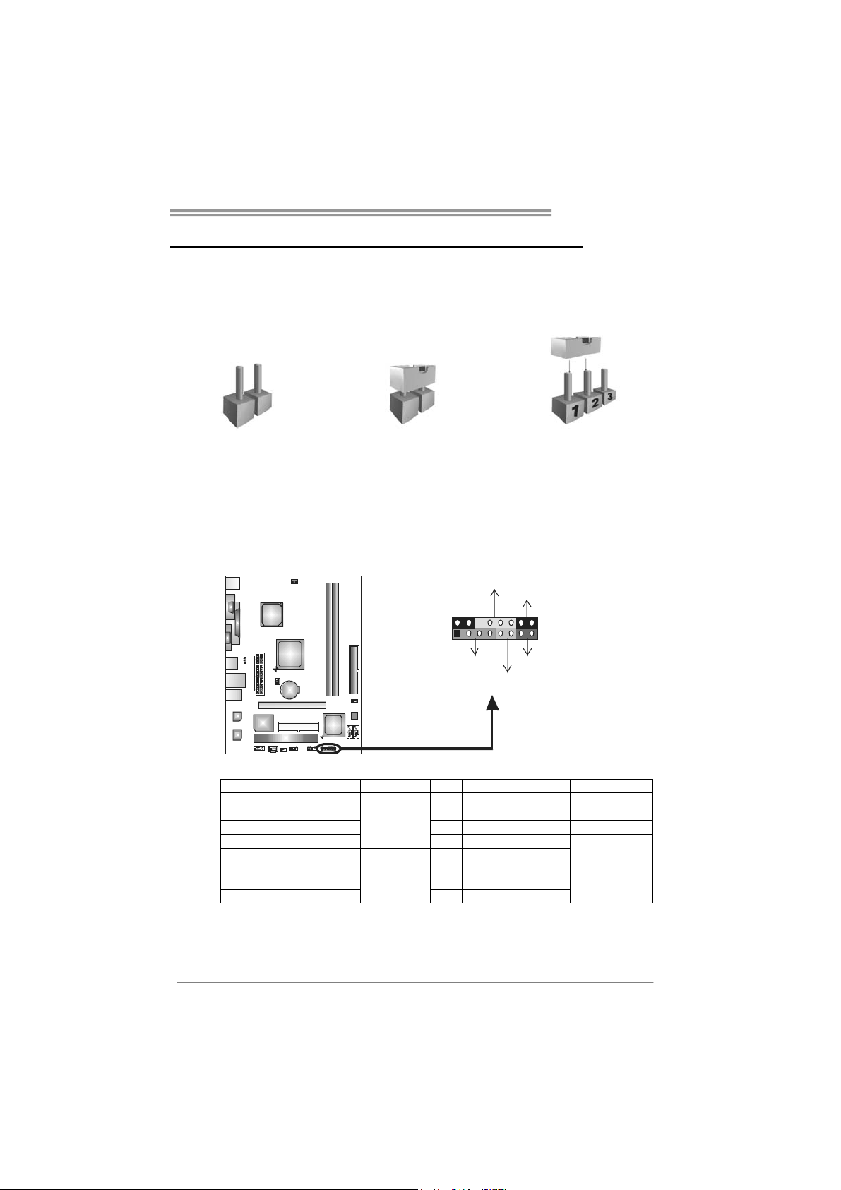
PANEL1: Front Panel Header
This 16-pin connector includes Power-on, Reset, HDD LED, Power LED, Sleep
button, and speaker connections. It allows user to connect the PC case’s front
panel switch functions.
PWR_LED
ON/OFF
-
9
1
++
+
SPK
HLED
16
8
-
+
RST
Pin Assignment Function Pin Assignment Function
1 +5V 9 Sleep control
2 N/A 10 Ground
3 N/ A 1 1 N/A N/A
4 Speaker
5 HDD LED (+) 13 Power LED (+)
6 HDD LED (-)
7 Ground 15 Power button
8 Reset control
Speaker
Connector
Hard drive
LED
Reset button
12 Power LED (+)
14 Power LED (-)
16 Ground
Sleep button
Power LED
Power-on button
11
Page 14

Motherboard Manual
F_USB1/F_USB2: Headers for USB 2.0 Ports at Front Panel
This motherboard provides 2 USB 2.0 headers, providing user to connect
additional USB cable on the PC front panel, and also can be connected with
internal USB devices, like USB card reader.
F_USB1 F_USB2
210
19
JUSBV1/JUSBV2: Power Source Headers for USB Ports
Pin 1-2 Close:
JUSBV1: +5V for USB ports at USB1/RJ45USB1.
JUSBV2: +5V for USB ports at front panel (F_USB1/F_USB2).
Pin 2-3 Close:
JUSBV1: +5V STB for USB ports at USB1/RJ45USB1.
JUSBV2: +5V STB for USB ports at front panel (F_USB1/F_USB2).
Pin Assignment
1 +5V (fused)
2 +5V (fused)
3 USB4 USB5 USB+
6 USB+
7 Ground
8 Ground
9 Key
10 NC
12
13
JUSBV1
3
1
13
JUSBV2
Pin 1-2 close
13
Pin 2-3 close
Note:
In order to support this function “Power-On system via USB device,” “JUSBV1/ JUSBV2”
jumper cap should be placed on Pin 2-3 individually.
Page 15

Viotech 3100+
F_AUDIO1: Front Panel Audio Header
This header allows user to connect the front audio output cable with the PC front
panel. It will disable the output on back panel audio connectors.
Pin Assignment
1 Mic Left in
2 Ground
3 Mic Right in
4 GPIO
5 Right line in
6 Jack Sense
7 Front Sense
8 Key
210
19
9 Left line in
10 Jack Sense
JSPDIFOUT1: Digital Audio-out Connector
This connector allows user to connect the PCI bracket SPDIF output header.
Pin
Assignment
1 +5V
2 SPDIF_OUT
3 Ground
13
13
Page 16

Motherboard Manual
JCMOS1: Clear CMOS Header
Placing the jumper on pin2-3 allows user to restore the BIOS safe setting and
the CMOS data. Please carefully follow the procedures to avoid damaging the
motherboard.
※ Clear CMOS Procedures:
1. Remove AC power line.
2. Set the jumper to “Pin 2-3 close”.
3. Wait for five seconds.
4. Set the jumper to “Pin 1-2 close”.
5. Power on the AC.
6. Reset your desired password or clear the CMOS data.
13
13
Pin 1-2 Close:
Normal Operation (Default).
13
Pin 2-3 Close:
Clear CMOS data.
14
Page 17

CHAPTER 4: RAID FUNCTIONS
Viotech 3100+
4.1 O
Supports Windows XP, Windows Vista 32, and Windows 7
PERATING SYSTEM
4.2 RAID ARRAYS
RAID supports the following types of RAID arrays:
RAID 0: RAID 0 defines a disk striping scheme that improves disk read and write times for
many applications.
RAID 1: RAID 1 defines techniques for mirroring data.
4.3 HOW RAID WORKS
RAID 0:
The controller “stripes” data across multiple drives in a RAID 0 array system. It breaks
up a large f ile into smal ler blo cks and p erfo rms disk r eads and wr ites a cross mu ltip le
drives in parallel. The size of each block is determined by the stripe size parameter,
which you set during the creation of the RAID set based on the system environment. This
technique reduces overall disk access time and offers high bandwidth.
Features and Benefits
Drives: Minimum 1, and maximum is up to 6 or 8. Depending on the
platform.
Uses: Intended for non-critical data requiring high data throughput, or any
environment that does not require fault tolerance.
Benefits: provides increased data throughput, especially for large files. No
capacity loss penalty for parity.
Drawbacks: Does not deliver any fault tolerance. If any drive in the array
fails, all data is lost.
Fault Tolerance: No.
Block 1
Blo ck 3
Blo ck 5
Block 2
Blo ck 4
Blo ck 6
15
Page 18

Motherboard Manual
RAID 1:
Every read and write is actually carried out in parallel across 2 disk drives in a RAID 1
array system. The mirrored (backup) copy of the data can reside on the same disk or on a
second redundant drive in the array. RAID 1 provides a hot-standby copy of data if the
active volume or drive is corrupted or becomes unavailable because of a hardware failure.
RAID techniques can be applied for high-availability solutions, or as a form of automatic
backup that eliminates tedious manual backups to more expensive and less reliable
media.
Features and Benefits
Drives: Minimum 2, and maximum is 2.
Uses: RAID 1 is ideal for small databases or any other application that
requires fault tolerance and minimal capacity.
Benefits: Provides 100% data redundancy. Should one drive fail, the
controller switches to the other drive.
Drawbacks: Requires 2 drives for the storage space of one drive.
Performance is impaired during drive rebuilds.
Fault Tolerance: Yes .
16
Block 1
Block 2
Block 3
Block 1
Block 2
Block 3
Page 19

CHAPTER 5: USEFUL HELP
Viotech 3100+
5.1 D
RIVER INSTALLATION NOTE
After you installed your operating system, please insert the Fully Setup
Driver CD into your optical drive and install the driver for better system
performance.
You will see the following window after you insert the CD
The setup guide will auto detect your motherboard and operating system.
Note:
If this window didn’t show up after you insert the Driver CD, please use file browser to
locate and execute the file SETUP.EXE under your optical drive.
A. Driver Installation
To install the driver, please click on the Driver icon. The setup guide will
list the compatible driver for your motherboard and operating system.
Click on each device driver to launch the installation program.
B. Software Installation
To install the software, please click on the Software icon. The setup guide
will list the software available for your system, click on each software title
to launch the installation program.
C. Manual
Aside from the paperback manual, we also provide manual in the Driver
CD. Click on the Manual icon to browse for available manual.
Note:
You will need Acrobat Reader to open the manual file. Please download the latest version
of Acrobat Reader software from
http://www.adobe.com/products/acrobat/readstep2.html
17
Page 20

Motherboard Manual
5.2 AMI BIOS BEEP CODE
Boot Block Beep Codes
Number of Beeps Description
1 No media present. (Insert diskette in floppy drive A:)
2
3 Insert next diskette if multiple diskettes are used for recovery
4 Flash Programming successful
5 File read error
7 No Flash EPROM detected
10 Flash Erase error
11 Flash Program error
12 “AMIBOOT.ROM” file size error
13
POST BIOS Beep Codes
Number of Beeps Description
1 Memory refresh timer error
3 Base memory read/write test error
6 Keyboard controller BAT command failed
7 General exception error (processor exception interrupt error)
8 Display memory error (system video adapter)
“AMIBOOT.ROM” file not found in root directory of diskette in
A:
BIOS ROM image mismatch (file layout does not match
image present in flash device)
Troubleshooting POST BIOS Beep Codes
Number of Beeps Troubleshooting Action
1, 3 Reseat the memory, or replace with known good modules.
Fatal error indicating a serious problem with the system.
Consult your system manufacturer. Before declaring the
motherboard beyond all hope, eliminate the possibility of
interference by a malfunctioning add-in card. Remove all
expansion cards except the video adapter.
6, 7
8
18
z If beep codes are generated when all other expansion
cards are absent, consult your system manufacturer’s
technical support.
z If beep codes are not generated when all other expansion
cards are absent, one of the add-in cards is causing the
malfunction. Insert the cards back into the system one at a
time until the problem happens again. This will reveal the
malfunctioning card.
If the system video adapter is an add-in card, replace or
reseat the
video adapter. If the video adapter is an integrated part of the
system board, the board may be faulty.
Page 21

5.3 EXTRA INFORMATION
CPU Overheated
If the system shutdown automatically after power on system for
seconds, that means the CPU protection function has been activated.
When the CPU is over heated, the motherboard will shutdown
automatically to avoid a damage of the CPU, and the system may not
power on again.
In this case, please double check:
1. The CPU cooler surface is placed evenly with the CPU surface.
2. CPU fan is rotated normally.
3. CPU fan speed is fulfilling with the CPU speed.
After confirmed, please follow steps below to relief the CPU
0protection function.
1. Remove the power cord from power supply for seconds.
2. Wait for seconds.
3. Plug in the power cord and boot up the system.
Or you can:
1. Clear the CMOS data.
(See “Close CMOS Header: JCMOS1” section)
2. Wait for seconds.
3. Power on the system again.
Viotech 3100+
19
Page 22

Motherboard Manual
5.4 TROUBLESHOOTING
Probable Solution
1. There is no power in the system.
Power LED does not shine; the
fan of the power supply does not
work
2. Indicator light on keyboard does
not shine.
System is inoperative. Keyboard lights
are on, power indicator lights are lit,
and hard drives are running.
System does not boot from a hard disk
drive, but can be booted from optical
drive.
System only boots from an optical
drive. Hard disks can be read,
applications can be used, but system
fails to boot from a hard disk.
Screen message shows “Invalid
Configuration” or “CMOS Failure.”
System cannot boot after user installs a
second hard drive.
1. Make sure power cable is
securely plugged in.
2. Replace cable.
3. Contact technical support.
Using even pressure on both ends of
the DIMM, press down firmly until the
module snaps into place.
1. Check cable running from disk to
disk controller board. Make sure
both ends are securely plugged
in; check the drive type in the
standard CMOS setup.
2. Backing up the hard drive is
extremely important. All hard
disks are capable of breaking
down at any time.
1. Back up data and applications
files.
2. Reformat the hard drive.
Re-install applications and data
using backup disks.
Review system’s equipment. Make sure
correct information is in setup.
1. Set master/slave jumpers
correctly.
2. Run SETUP program and select
correct drive types. Call the drive
manufacturers for compatibility
with other drives.
20
Page 23

Viotech 3100+
This page is intentionally left blank.
21
Page 24

Motherboard Manual
APPENDIX: SPEC IN OTHER LANGUAGES
G
ERMAN
Sp ezif ika tio nen
NanoBGA2
CPU
FSB
Chipsatz
Grafik Chrome9 HC GFX
Super E/A
Arbeitsspeich
er
IDE Integ r iert er IDE - C o ntro l le r
SATA Integrierter Serial ATA-Controller
VIA CPU On-board
VIA C7-D 1.8G CPU
VIA V4 BUS 800MHz
VIA CN896
VIA VT8237S
ITE 8712F
Biet et die h äuf ig v er wend eten alten S up er
E/A-Funktionen.
Low Pin Count-Schnittstelle
DDR2 DIMM-Steckplätze x 2
Jeder DIMM unterstützt 256MB/512MB/1GB
DDR2
Max. 2GB Arbeitsspeicher
Unterstützt DDR2 533 / 667
Unterstützt Hyper-Threading
Execute Disab le B it
Extended Memory 64 Technology
Max. 64/128/256MB gemeinsam benutzter
Videospeicher
Umgebungskontrolle,
Hardware-Überwachung
Lüfterdrehz ahl-Controller
"Smart Guardian"-Funktion von ITE
Ein-Kanal DDR2 Speichermodul
registrierte DIMMs. ECC DIMMs werden nicht
unterstützt.
Ultra DMA 33 / 66 / 100 / 133 Bus Master-Modus
Unterstützt PIO-Modus 0~4
Datentransferrate b is zu 3Gb/s
Konform mit der SATA-Spezifikation Version 2.0
LAN VIA VT6113
Audio-Codec VIA VT1708B
PCI-Steckp lat z x1
Steckplätze
PCI Express x16 Steckplatz x1
10 / 100 Mb/s Auto-Negotiation
10 / 100 / 1000 Mb/s Auto-Negotiation
5.1-Kanal-Audioausgabe
Unterstützt High-Definition Audio
22
Page 25

Onboard-Ans
chluss
Rückseiten-E
/A
Platinengröße
OS-Unterstüt
zung
Viotech 3100+
Sp ezif ika tio nen
IDE-Anschluss x1 Jeder Anschluss unterstützt 2 IDE-Laufwerke
Diskettenlaufwerkanschluss x1 Jeder Anschluss unterstützt 2 Diskettenlaufwerke
SATA-Anschluss x2 Jeder Anschluss unterstützt 1 SATA-Laufwerk
Fronttafelanschluss x1 Unterstützt die Fronttafelfunktionen
Front-Audioanschluss x1 Unterstützt die Fronttafel-Audioanschlussfunktion
S/PDIF Ausgangsanschluss x1 Unterstützt die digitale Audioausgabefunktion
CPU-Lüfter-Sockel x1 CPU-Lüfterstromversorgungsanschluss
System-Lüfter-Sockel x1 System-Lüfter-Stromversorgungsanschluss
"CMOS löschen "- Sockel x1
USB-Anschluss x2
Stromanschluss (24-polig) x1
PS/2-Tastatur x1
PS/2- Maus x1
Serieller Anschluss x1
Druckeranschluss x1
VGA-Anschluss x1
LAN-Anschluss x1
USB-Anschluss x4
Audioanschluss x3
180 mm (B) X 223 mm (L)
Windows XP / Vista / 7
Jeder Anschluss unterstützt 2
Fronttafel-USB-Anschlüsse
Biostar behält sich das Recht vor, ohne
Ankündigung die Unterstützung für ein
Betriebssystem hinzuzufügen oder zu entfernen.
23
Page 26

Motherboard Manual
FRENCH
NanoBGA2
UC
Bus frontal
Chipset
Graphiques
Super E/S
VIA CPU On-board
VIA C7-D 1.8G CPU
VIA V4 BUS 800MHz
VIA CN896
VIA VT8237S
Chrome9 HC GFX
ITE 8712F
Fournit la fonctionnalité de Super E/S
patrimoniales la plus utilisée.
Int e r face à fa ib le co mpte d e b roches
SPEC
Prend en charge les techno logies
Hyper-Threading
d'exécution de bit de désactivation
de mémoire étendu e 64
Mémo ire v id éo p art agée max imale de
64/128/256 Mo
Initiatives de contrôle environnementales,
Mon iteur d e mat ériel
Contrôleur de vitesse de ventilateur
Fonction "Gardien intelligent" de l'ITE
Mémoire
principale
IDE
SATA
LAN
Codec audio
Fentes
24
Fentes DDR2 DIMM x 2
Chaque DIMM prend en charge des DDR2 de
256Mo/512Mo/1Go
Capacité mémo ir e max imale de 2 Go
Prend en charge la DDR2 533 / 667
Contrôleur IDE intégré
Contrô leur Serial ATA int é g r é :
VIA VT6113
VIA VT1708B
Fente PCI x1
Fente PC I Expres s x16 x1
Modu le d e mémo ire DDR2 à mod e à s imp le vo ie
Les DIMM à registres et DIMM avec code
correcteurs d'err eurs ne so nt pas prises en
charg e
Mode principa le de Bus Ultra D MA 33 / 66 / 100 /
133
Prend en charge le mode PIO 0~4,
Taux de transfert jusqu'à 3 Go/s.
Co n forme à la spéc if i cat ion S ATA Vers ion 2.0
10 / 100 Mb/s négociation automat ique
10 / 100 / 1000 Mb/s négociation automatique
Sortie audio à 5 .1 vo ies
Prise en ch arg e de l'aud io haut e définition
Page 27

SPEC
Connecteur IDE x1
Viotech 3100+
Chaque connecteur pr end en ch arge 2
périphériques IDE
Connecteur
embarqu é
E/S du
panneau
arrière
Dimensions
de la carte
Support SE
Connecteur de disquette x1
Connecteur SATA x2
Connecteur du panneau avant x1
Connecteur Audio du panneau avant x1
Connecteur de sortie S/PDIF x1
Embase de ventilateur UC x1
Embase de ventilateur système x1 Alimentation électrique du ventilateur système
Embase d'effacement CMOS x1
Connecteur USB x2
Connecteur d'alimentat ion (24 broches) x1
Clavier PS/2 x1
Souris PS/2 x1
Port série x1
Port d'imprimante x1
Port VGA x1
Port LAN x1
Port US B x4
Fiche aud io x3
180mm (l) X 223 mm (H)
Windows XP / Vista / 7
Chaque conn ector prend en ch arge 2 lecteurs de
disquettes
Chaque connecteur pr end en ch arge 1
périphérique SATA
Prend en charge les équipements du panneau
avant
Prend en charge la fonction audio du panneau
avant
Prend en charge la fonction de sortie audio
numérique
Alimentation électrique du ventilateur UC
Chaque connecteur pr end en ch arge 2 port s USB
de panneau avant
Biostar se réserve le droit d'ajouter ou de
supprimer le support de SE avec ou sans préavis.
25
Page 28

Motherboard Manual
ITALIAN
SPECIFICA
CPU
FSB
Chipset
Grafica
Super I/O
Memoria
principale
NanoBGA2
VIA CPU On-board
VIA C7-D 1.8G CPU
VIA V4 BUS 800MHz
VIA CN896
VIA VT8237S
Chrome9 HC GFX
ITE 8712F
Fo rnis ce le fu nzionalità legacy Sup er I/O
usate più comunemente.
Interfaccia LPC (Low Pin Count)
Alloggi DIMM DDR2 x 2
Ciascun DIMM supporta DDR2
256MB/512MB/1GB
Capacità massima della memoria 2GB
Supporto di DDR2 533 / 667
Supporto di Hyper-Threading
Execute Disable Bit
Tecnologia Extended Memory 64
La me mo r ia vid eo cond ivis a m as s ima è di
64/128/256MB
Funzioni di controllo dell’ambiente:
Monitoraggio hardware
Co n troller velo c it à ven t o lina
Funzione "Smart Guardian" di ITE
Modulo di memoria DDR2 a canale singolo
DIMM registrati e DIMM ECC non sono
supportati
IDE
SATA
LAN
Codec
audio
Allo g g i
26
Co n t roller IDE int egrato
Co n troller Ser ia l ATA int egrato
VIA VT6113
VIA VT1708B
Allo g g io PC I x 1
Alloggio PCI Express x16 x1
Modalità Bus Master Ultra DMA 33 / 66 / 100 / 133
Supporto modalità PIO Mode 0-4
Velocità di trasferimento dei dati fino a 3
Gb/s.
Co mp atibi le s pecifi che SATA Ver s io ne 2.0 .
Negoziazione automatica 10 / 100 Mb/s
Negoziazione automatica 10 / 100 / 1000 Mb/s
Uscita audio 5.1 canali
Supporto audio High-Definition (HD)
Page 29

Connettori
su scheda
I/O
pannello
posteriore
Dimension
i scheda
Sistemi
operativi
supportati
Viotech 3100+
SPECIFICA
Connettore IDE x1 Ciascun connettore supporta 2 unità IDE
Connettore floppy x1 Ciascun connettore supporta 2 unità Floppy
Connettore SATA x2 Ciascun connettore supporta 1 unità SATA
Co n nett o re p an nello fro n t ale x1 Sup po rta i s ervizi de l pann e llo fro ntale
Connettore audio frontale x1 Supporta la funzione audio pannello frontale
Connettore output S/PDIF x1 Supporta la funzione d’output audio digitale
Co llettore ven tolina C PU x1 Alimentazione vent o l ina CPU
Co llettore ven tolina s is t em a x 1 Alimentazione vent o l ina d i sistema
Co llettore cance l laz ione CMO S x1
Connettore USB x2
Connettore alimentaz ione (24 pin) x 1
Tas t ie r a P S /2 x 1
Mou s e PS/2 x 1
Porta seriale x1
Port a stampante x1
Porta VGA x1
Porta LAN x1
Porta USB x4
Connettore audio x3
180 mm (larghezza) x 223 mm (altezza)
Windows XP / Vista / 7
Ciascun connettore supporta 2 porte USB
pannello frontale
Biostar si riserva il diritto di aggiungere o
rimuovere il supporto di qualsiasi sistema
operativo senza preavviso.
27
Page 30

Motherboard Manual
SPANISH
Especificación
NanoBGA2
CPU
FSB
Conjunto de
chips
Gráficos Chrome9 HC GFX
Súper E/S
Memoria
principal
VIA CPU On-board
VIA C7-D 1.8G CPU
VIA V4 BUS 800MHz
VIA CN896
VIA VT8237S
ITE 8712F
Le ofrece las funcionalidades heredadas de
us o más co mú n Súper E /S.
Interfaz de cuenta Low Pin
Ranuras DIMM DDR2 x 2
Cada DIMM admite DDR2 de 256MB/512MB
/1GB
Capacidad máxima de memoria de 2GB
Admite DDR2 de 533 / 667
Admite Hyper-Threading
Bit de deshabilitación de ejecución
Tecnología Extended Memory 64
Memo r ia máx ima de vídeo co mpartid a de
64/128/256MB
In iciat ivas de co ntro l d e ent o r no,
Monitor hardware
Controlador de velocidad de ventilador
Función "Guardia inteligente" de ITE
Módulo de memoria DDR2 de canal Sencillo
No admite DIMM registrados o DIMM compatibles
con ECC
IDE Controlador IDE integrado
SATA Controlador ATA Serie Integrado
Red Local VIA VT6113
Códecs de
sonido
Ranuras
VIA VT1708B
Ranura PCI X1
Ranura PCI Express x16 X1
28
Modo bus maestro Ultra DMA 33 / 66 / 100 / 133
Soporte los Modos PIO 0~4.
Tasas de transferencia de hasta 3 Gb/s.
Co mp at ib le co n la ve rs ió n SATA 2.0.
Negociación de 10 / 100 Mb/s
Negociación de 10 / 100 / 1000 Mb/s
Salida de sonido de 5.1 canales
Soporte de sonido Alta Definición
Page 31

Conectores
en p laca
Viotech 3100+
Especificación
Conector IDE X1 Cada conector soporta 2 dispositivos IDE
Conector disco flexible X1 Cada conector soporta 2 unidades de disco flexible
Conector SATA X2 Cada conector soporta 1 dispositivos SATA
Co n ector d e p ane l f ron t a l X1 Soport a in s t a la c io n es en e l pan e l fro n ta l
Conector de sonido frontal X1 Soporta funciones de sonido en el panel frontal
Conector de salida S/PDIF X1 Soporta función de salida de sonido digital
Cabecera de ventilador de CPU X1 Fuente de alimentación de ventilador de CPU
Cabecera de ventilador de sistema X1 Fuente de alimentación de ventilador de sistema
Cabecera de borrado de CMOS X1
Conector USB X2 Cada conect or so po rta 2 puerto s USB frontales
Panel
trasero de
E/S
Ta mañ o de
la placa
Soporte de
sistema
operativo
Conector de alimentación X1
(24 patillas)
Tec lad o P S /2 X1
Ratón PS/2 X1
Puert o serie X1
Puerto de impresora X1
Puerto VGA X1
Puerto de red local X1
Puert o USB X4
Conector de sonido X3
180 mm. (A) X 223 mm. (H)
Biostar se reserva el derecho de añadir o retirar el
Windows XP / Vista / 7
soporte de cualquier SO con o sin aviso previo.
29
Page 32

Motherboard Manual
PORTUGUESE
ESPECIFICAÇÕES
CPU
FSB
Chipset
Placa
gráf ica
Especificaçã
o Super I/O
Memória
principal
NanoBGA2
VIA CPU On-board
VIA C7-D 1.8G CPU
VIA V4 BUS 800MHz
VIA CN896
VIA VT8237S
Chrome9 HC GFX
ITE 8712F
Proporciona as funcionalidades mais utilizadas
em termos da especificação Super I/O.
Interface LPC (Low Pin Count).
Ranhuras DIMM DDR2 x2
Cada módulo DIMM suporta uma memória
DDR2 de 256MB/512 MB/1GB
Capacidad e máx ima de me mó r ia: 2GB
Suporta módulos DDR2 533 / 667
Suporta as t ecno log ias H yper-Thr ead ing
Execute Disab le B it
Extended Memory 64
Memória de vídeo máxima partilhada:
64/128/256 MB
In iciat ivas par a contro lo do amb iente
Monitorização do hard ware
Controlador da velocidade da ventoinha
Função "S mart Guard ian" d a ITE
Módu lo de me mó r ia DDR2 d e canal s imp les
Os módulos DIMM registados e os DIMM ECC
não são suportados
IDE
SATA
LAN
Codec de
som
Ranhuras
30
Controlador IDE integrado
Controlador Serial ATA integrado
VIA VT6113
VIA VT1708B
Ranhura PCI x1
Ranhura PCI Express x16 x1
Modo Bus master Ultra DMA 33 / 66 / 100 / 133
Suporta o modo PIO 0~4.
Velocidades de transmissão de dados até 3 Gb/s.
Co mpat ib ilidad e com a espe c if ic a ção S ATA
versão 2.0 .
Auto negociação de 10 / 100 Mb/s
Auto negociação de 10 / 100 / 1000 Mb/s
Saída de áudio de 5.1 canais
Suporta a especificação High-Definition Audio
Page 33

Conectores
na placa
Entradas/S
aídas no
painel
traseiro
Tamanho
da placa
Viotech 3100+
ESPECIFICAÇÕES
Conector IDE x1 Cada conector suporta 2 dispositivos IDE
Conector da unidade de disquetes x1 Cada conector suporta 2 unidades de d isquetes
Conector SATA x2 Cada conector suporta 1 dispositivo SATA
Conector do painel frontal x1 Para suporte de várias funções no painel frontal
Conector de áud io frontal x1 Suporta a fun ção de áudio no paine l frontal
Conector de s aída S/ PD IF x1 S up orta a sa ída de áudio d igital
Conector da ventoinha da CPU x1 Alimentação da vento inha da CPU
Conector da ventoinha do sistema x1 Alimentação da ventoinha do sistema
Conector para limpeza do CMOS x1
Conector USB x2
Conector de alimentação (24 pinos) x1
Tec lad o P S /2 x 1
Rato PS/2 x1
Porta s ér ie x 1
Porta para impressora x1
Porta VGA x1
Porta LAN x1
Porta USB x4
Tomada de audio x3
180 mm (L) X 223 mm (A)
Cada conector suporta 2 portas USB no painel
frontal
Sistemas
operativos
suportados
Windows XP / Vista / 7
A Biostar reserva-se o direito de adicionar ou
remover suporte para qualquer sistema
operativo com ou sem aviso prévio.
31
Page 34

Motherboard Manual
j
POLISH
NanoBGA2
Procesor
FSB
Chipset
Graf ika
Pamięć
główna
VIA CPU On-board
VIA C7-D 1.8G CPU
VIA V4 BUS 800MHz
VIA CN896
VIA VT8237S
Chrome9 HC GFX
Gniazda DDR2 DIMM x 2
Każde gniazdo DIMM obs ługuje moduły
256MB/512MB/1GB DDR2
Maks. wielkość pamięci 2GB
Obsługa DDR2 533 / 667
SPEC
Obsługa Hyper-Threading
Execute Disab le B it
Extended Memory 64 Technology
Maks. wielkość współdz ielo n ej pamięci video
wynosi 64/128/256MB
Mod uł pamięci DDR2 z trybem pojedynczego
kana łu
Brak obsług i Register ed D IMM oraz ECC D IMM
Super I/O
IDE
SATA
LAN
Kodek
dźwiękowy
Gniazda
32
ITE 8712F
Zapewnia najbardziej powszechne funkc
I/O.
Interfejs Low Pin Count
Zintegrowany kontroler IDE
Zintegrowany kontroler Serial ATA
VIA VT6113
VIA VT1708B
Gniazdo PCI x1
Gniazdo PCI Express x16 x1
e Super
Funkcje kontroli warunków pracy,
Mon itor H /W
Kontroler prędkości wenty latora
Funkcja ITE "Smart Guard ian"
Ultra DMA 33 / 66 / 100 / 133 Tryb Bus Master
obsługa PIO tryb 0~4
Transfer danych do 3 Gb/s.
Zgodność ze specyfikacją SATA w wers j i 2. 0.
10 / 100 Mb/s z automatyczną negocjacją
szybkości
10 / 100 / 1000 Mb/s z automatyczn ą negocjacją
szybkości
5.1 kanałowe wyjście audio
Obsługa H ig h-Def i n ition A u d io
Page 35

Złącza
wbud owane
Back Panel
I/O
Wymiary
płyty
Obsluga
systemu
operacyjne
go
Viotech 3100+
SPEC
Złącze IDE x1 Każde złącze obs ługuje 2 urządzenia IDE
Złącze napędu dyskietek x1 Każde złącze obs ługuje 2 napędy dyskietek
Złącze SATA x 2 Każde złącze obs ługuje 1 urządzenie SATA
Złącze panela przedniego x1 Obsługa elementów panela przedniego
Przedn ie złącze aud io x1 Obsługa funkcji audio na panelu przednim
Złącze wyjścia S/PDIF x1 Obsługa funkcj i cyfrowego wyjścia aud io
Złącze główkowe wentylatora procesora x1 Zasilanie wentylatora procesora
Złącze główkowe wenty latora
systemowego x2
Złącze główkowe kaso wania CMOS x1
Złącze USB x2
Złącze zasilania (24 pinowe) x1
Klawiatura PS/2 x1
Mys z PS /2 x1
Port szeregowy x1
Port drukarki x1
Port VGA x1
Port LAN x1
Port US B x4
Gniazdo audio x3
180 mm (S) X 223 mm (W)
Windows XP / Vista / 7
Zasilanie wentylatora systemowego
Każde złącze obs ługuje 2 porty USB na panelu
przednim
Biostar zastrzega sobie prawo dodawania lub
odwoływania obsług i dowo lnego s yst emu
operacyjnego b ez po wiad o mienia.
33
Page 36

Motherboard Manual
RUSSIAN
CPU
(центральн
ый
процессор)
FSB
Набо р
микросхем
Графика
Основная
память
Super I/O
IDE
SATA
Локальная
сеть
Звуко во й
кодек
Слоты
34
NanoBGA2
VIA CPU On-board
VIA C7-D 1.8G CPU
VIA V4 BUS 800МГц
VIA CN896
VIA VT8237S
Chrome9 HC GFX
Слоты DDR2 DIMM x 2
Каждый модуль DIMM поддерживает 256МБ
/512МБ/1ГБ DDR2
Максимальная ёмкос ть памяти 2ГБ
Поддержка DDR2 533 / 667
ITE 8712F
Обеспечивает наиболее использ уемые
действующие фун кц ион ал ьны е возможности
Super I/O.
Интерфейс с низким количество м выводов
Встроенное устройство упр авл ени я
встроенными интерфейсами устройств
Встроенное последо ват ельное устройство
упра вления ATA
VIA VT6113
VIA VT1708B
Слот PCI x1
Слот PCI Express x16 x1
СПЕЦ
Поддержка технологий Hyper-Threading
Execute Disab le B it
Extended Memory 64 Technology
Максимальная совместно используемая видео
память составляет 64/128/256 МБ
Мод уль памяти с одноканальным режимом
DDR2
Не поддерживает зарегистрированные
модули DIMM and ECC DIMM
Инициативы по охране окружающей среды,
Аппаратный монитор
Регул ятор скорости
Функц ия ITE "Smart Gu ard ian"
(Интеллектуальная защита)
Режим "хозяина" шины Ultra DMA 33 / 66 / 100
/ 133
Поддержка режима PIO 0~4,
скорость передачи данных до 3 гигабит/с.
Соответствие спецификации SATA версия 2.0.
Автоматическо е сог лас овани е 10 / 100 Мб /с
Автоматическо е сог лас овани е 10 / 100 / 1000
Мб/с
5.1канальный звуковой вых од
Звуко ва я поддержка High-Def in it io n
Page 37

Встроенны
й разъём
Задняя
панель
средств
ввода-выв
ода
Разм ер
панели
Поддержка
OS
Viotech 3100+
СПЕЦ
Разъ ём IDE x1
Разъ ём НГМ Д x1
Разъ ём SATA x2
Разъ ём на лицевой панели x1 Поддержка устройств на лицевой панели
Входной звуковой разъём x1
Разъ ём вывода для S/PDIF x1
Контактирующее приспособление
вентил ятора центрального
процессора x1
Контактирующее приспособление
вентил ятора системы x1
Открытое контактир ующе е
приспособление CMOS x1
USB- разъём x2
Разъ ем питания (24 выво д) x1
Клавиатура PS/2 x1
Мышь PS/2 x 1
Последоват ельны й порт x1
Пор т подключения принтера x1
Пор т VGA x1
Пор т LAN x1
USB- порт x4
Гнездо для подключени я наушников x3
180 мм (Ш) X 223 мм (В)
Windows XP / Vista / 7
Каждый разъём поддерживает 2 встроенных
интерфейса накопителей
Каждый разъём поддерживает 2 накопителя
на гибких магнитных дисках
Каждый разъём поддерживает 1 устр ойство
SATA
Поддержка звуко вых функций на лицевой
панели
Поддержка выво да цифровой звуковой
функц ии
Источник питания для вентилято р а
центрального процессора
Источник питания для вентилято р а системы
Каждый разъём поддерживает 2 USB-порта на
лицевой панели
Biostar сохраняет за собой право добавлять
или удалять средства обеспечения для OS с
или без предварительного уведо мл ени я.
35
Page 38

Motherboard Manual
ARABIC
تﺎﻔﺻاﻮﻤﻟا
تﺎﻴﻨﻘﺗ ﻢﻋﺪﺗHyper-Thr eading
Execute Disab le B it
Extended Memory 64 Technology
ﺔآﺮﺘﺸﻤﻟا ﻮﻳﺪﻴﻔﻟا ةﺮآاﺬﻟ ﺔﻌﺳ ﻰﺼﻗأ64/128/256ﺖﻳﺎﺏ ﺎﺠﻴﻡ
ةﺪﺣو ةﺮآاذ DDR2 ﺔﻳدﺎﺣأ ةﺎﻨﻘﻟا
ةﺮآاﺬﻟا ﻖﺋﺎﻗر ﻢﻋﺪﺗ ﻻDIMM ﻊﻡ ﻖﻓاﻮﺘﺗ ﻻ ﻲﺘﻟا ﻚﻠﺗو ECC
ﻞﺋﺎﺳو ﻢﻜﺤﺘﻟا ﻲﻓ ﺔﺌﻴﺒﻟا:
ﺐﻗاﺮﻡ ﺔﻓﺮﻌﻤﻟ ﺔﻟﺎﺣ ةﺰﻬﺝﻷا
ﺐﻗاﺮﻡ ﻲﻓ ﺮﺳﺔﻋ ﺔﺣوﺮﻤﻟا
ﺔﻔﻴﻇو"S mart Gu ard ian" ﻦﻡ ITE
ﺔﻴﻨﻘ ﺘﺏ ﻞﻗﺎﻥUltra DMA 33 / 66 / 100 / 133
ﻲﺴﻴﺋر ﻊﺿو
NanoBGA2
VIA CPU On-board
VIA C7-D 1.8G CPU
ددﺮﺗ VIA V4 BUS 800 ﺰﺗﺮه ﺎﺠﻴﻡ
VIA CN896
VIA VT8237S
Chrome9 HC GFX
ﺔﺤﺘﻓDDR2 DIMMدﺪﻋ2
ﺔﺤﺘﻓDIMM عﻮﻥ ﻦﻡ ةﺮآاذ ﻢﻋﺪﺗ DDR2 ﺔﻌﺳ 256/512 ﺖﻳﺎﺏ ﺎﺠﻴﻡ
ىﻮﺼﻗ ةﺮآاذ ﺔﻌﺳ2 ﺖﻳﺎﺏ ﺎﺠﻴﺝ
عﻮﻥ ﻦﻡ ةﺮآاﺬﻟا ﻢﻋﺪﺗDDR2 تﺎﻌﺳ 533 / 667ﺖﻳﺎﺏ ﺎﺠﻴﻡ
ITE 8712F
ﺮﻓﻮﺗ ﺔﻔ ﻴﻇو Super I/O ﺮﺜآﻷا ًﺎﻡ ا ﺪ ﺨ ﺘ ﺳ ا.
ﺗﻢﻋﺪ ﺔﻴﻨﻘﺗ Low Pin Count Interface
ﻢﻜﺤﺘﻡIDE ﻞﻡﺎﻜﺘﻡ
و1/ ﺎﺠﻴﺝﺖﻳﺎﺏ
ﺔﺠﻟﺎﻌﻤﻟا ةﺪﺣو
ﺔﻳﺰآﺮﻤﻟا
ﻞﻗﺎﻨﻟا ﻲﻡﺎﻡﻷا ﻲﺒﻥﺎﺠﻟا
ﺢﺋاﺮﺸﻟا ﺔﻋﻮﻤﺠﻡ
تﺎﻡﻮﺳﺮﻟا ﺔﻗﺎﻄﺏ
ﺔﻴﺴﻴ ﺋﺮﻟا ةﺮآاﺬﻟا
Super I/O
ﺬﻔﻨﻡID E
36
ﻊﺿو ﻢﻋدPIO Mode 0~4
ﻰﻟإ ﻞﺼﺗ تﺎﻋﺮﺴﺏ تﺎ ﻥﺎﻴﺒﻟا ﻞﻘﻥ3 ﺖﺏﺎﺠﻴﺝ/ﺔﻴﻥﺎ ﺙ.
تﺎﻔﺹاﻮﻤﻟ ﺔﻘﺏﺎﻄﻡSATA راﺪﺹﻹا 2.0.
ﻲﺋﺎﻘﻠﺗ ضو ﺎﻔﺗ10/100 ﺖﻳﺎﺏ ﺎﺠﻴﻡ / ﺔﻴﻥﺎﺙ
ﻲﺋﺎﻘﻠﺗ ضو ﺎﻔﺗ10/100 ﺖﻳﺎﺏ ﺎﺠﻴﻡ /و ﺔﻴﻥﺎﺙ1ﺖﺏ ﺎﺠﻴﺝ/ﺔﻴﻥﺎﺙ
5.1 تاﻮﻨﻗ جﺮﺨﻟ تﻮﺼﻟا
ﻢﻋﺪﺗ ﺔﻴﻨﻘﺗ تﻮﺼﻟا ﻲﻟ ﺎﻋ ﻒﻳﺮﻌﺘﻟا ﻦﻡ
ﻢﻜﺤﺘﻡSerial ATAﻞﻡﺎﻜﺘﻡ
VIA VT6113
VIA VT1708B
ﺔﺤﺘﻓPCI دﺪﻋ1
ﺔﺤﺘﻓx1 6 PCI Express دﺪﻋ1
SATA
ﺔﻜﺒﺵ ﺔﻴﻠﺥاد
10/100
تﻮﺼﻟا ﻚﻳدﻮآ
تﺎﺤﺘﻔﻟا
Page 39

تﺎﻔﺻاﻮﻤﻟا
Viotech 3100+
ﺬﻔﻨﻡID E دﺪﻋ1 ةﺰﻬﺝأ ﻦﻡ ﻦﻴﻨﺙا ﺬﻔﻨﻡ ﻞآ ﻢﻋﺪﻳIDE
ﺔﻥﺮﻡ صاﺮﻗأ كﺮﺤﻡ ﺬﻔﻨﻡ دﺪﻋ1 ﺔﻥﺮﻤﻟا صاﺮﻗﻸﻟ ﻦﻴآ ﺮﺤﻡ ﻢﻋﺪﻳ
ﺬﻔﻨﻡSATA دﺪﻋ2 ةﺰﻬﺝأ ﻦﻡ ﺪﺣاو ﺬﻔﻨﻡ ﻞآ ﻢﻋﺪﻳSATA
ﺔﻴﻡﺎﻡﻷا ﺔﺣﻮﻠﻟا ﺬﻔﻨﻡ دﺪﻋ1 ﺔﻴﻡﺎﻡﻷا ﺔﺣﻮﻠﻟا تاﺰﻴﻬﺠﺗ ﻢﻋﺪﻳ
ﻆﻔﺘﺤﺗBiostar وأ رﺎﻄﺥﺈﺏ ﻞﻴﻐﺸﺗ مﺎﻈﻥ يﻷ ﻢﻋﺪﻟا ﺔﻟازإ وأ ﺔﻓﺎﺿ إ ﻲﻓ ﺎﻬﻘﺤﺏ
ﻲﻡﺎﻡﻷا تﻮﺼﻟا ﺬﻔﻨﻡ دﺪﻋ 1 ﺔﻴﻡﺎﻡﻷا ﺔﺣﻮﻠﻟ ﺎﺏ تﻮﺼﻟا ﺔﻔﻴﻇو ﻢﻋﺪﻳ
جﺮﺥ ﺬﻔﻨﻡS/PDIF دﺪﻋ1 ﻲﻤﻗﺮﻟا تﻮﺼﻟا جﺮﺥ ﺔﻔﻴﻇو ﻢﻋﺪﻳ
ﻟا ﺢﻄﺳ ﻰﻠﻋ ﺬﻓﺎﻨﻤ
ﺔﺣﻮﻠﻟا
ﺔﻳﺰآﺮﻤﻟا ﺔﺠﻟﺎﻌﻤﻟا ةﺪﺣو ﺔﺣوﺮﻡ ﺔﻠﺹو دﺪﻋ1 ﺔﻔ ﻴﻇو ﻊﻡ ﺔﺠﻟﺎﻌﻤﻟا ةﺪﺣو ﺔﺣوﺮﻤﻟ ﺔﻗﺎﻄ ﻟا ﻞﻴﺹﻮﺘﻟ
مﺎﻈﻨﻟا ﺔﺣوﺮﻡ ﺔﻠﺹو دﺪﻋ1 مﺎﻈﻨﻟا ﺔﺣوﺮﻤﻟ ﺔﻗﺎﻄﻟا ﻞﻴﺹﻮﺘﻟ
ﺢﺴﻡ ﺔﻠﺹوCMOS دﺪﻋ1
ﻡ ﺬﻔﻨUS B دﺪﻋ2 ﻲﺘﺤﺘﻓ ﺬﻔﻨﻡ ﻞآ ﻢﻋﺪﻳUSBﺔﻴﻡﺎﻡﻷا ﺔﺣﻮﻠﻟﺎﺏ
ﺔﻗﺎﻄﻟا ﻞﻴﺹﻮﺗ ﺬﻔﻨﻡ)24سﻮﺏد( دﺪﻋ1
ﺢﻴﺗﺎﻔﻡ ﺔﺣﻮﻟPS/2 دﺪﻋ1
سوﺎﻡ PS/2 دﺪﻋ1
ﻲﻠﺴﻠﺴﺗ ﺬﻔﻨﻡ دﺪﻋ
ﺔﻌﺏﺎﻃ ﺬﻔﻨﻡ دﺪﻋ1
ﺬﻔﻨﻡVGA دﺪﻋ1
ﻞﺥد ﺬﻓﺎﻨﻡ/ جﺮﺥ
ﺔﻴﻔﻠﺨﻟا ﺔﺣﻮﻠﻟا
ﺔﻴﻠﺤﻡ لﺎﺼﺗا ﺔﻜﺒﺵ ﺬﻔﻨﻡ دﺪﻋ1
ﺬﻓﺎﻨﻡUS B دﺪﻋ4
ﻡتﻮﺹ ﺲﺒﻘ دﺪﻋ3
180 ﻢﻡ)ضﺮﻋ (X 223 ﻢﻡ)عﺎﻔﺗرا(
Windows XP / Vista / 7
رﺎﻄﺥإ نوﺪﺏ.
ﺔﺣﻮﻠﻟا ﻢﺠﺣ
ﻞﻴﻐﺸﺘﻟا ﺔﻤﻈﻥأ ﻢﻋد
37
Page 40

Motherboard Manual
JAPANESE
仕様
CPU
FSB
チップセット
グラフィック
ス
メインメモリ
Super I/O
NanoBGA2
VIA CPU On-board
VIA C7-D 1.8G CPU
VIA V4 BUS 800MHz
VIA CN896
VIA VT8237S
Chrome9 HC GFX 最大の共有ビデオ メモリ は64/128/256 MBです
DDR2 DIMMスロット x 2
各DIMMは256MB/512MB/1GB DDR2をサポ ート
最大メモリ容 量2GB
DDR2 533 / 667 をサポート
ITE 8712F
もっとも一般 に使 用されるレ ガシーSuper I/O機能を
採用していま す。
低ピンカウン トイ ンターフェ イス
Hyper-Threading
Execute Disab le B it
Extended Memory 64 Technology
シングル チ ャン ネルモードDDR2メモリモジ ュール
登録済みDIMMとECC DIMMはサポート されません
環境コントロ ール イニシアチ ブ、
H/Wモニ ター
ファン速度コ ント ローラ/ モニター
ITE の「スマート ガー ディアン」 機能
IDE
SATA
10/100 LAN
サウンド
Codec
スロット
38
統合ID Eコントローラ
Ultra DMA 33 / 66 / 100 / 133バスマ スタ モード
PIO Mode 0~4のサポート
最高3 Gb/秒の データ転送 速度
統合シリアルATA コントロー ラ
SATAバージョン2.0仕様に準拠。
10 / 100 Mb/秒のオ ートネ ゴシエーシ ョン
VIA VT6113
10 / 100 / 1000 Mb/秒のオ ートネゴシ エーション
5.1チャンネル オーディオ アウ ト
VIA VT1708B
ハイデフィニ ショ ンオーディ オのサポー ト
PCIスロット x1
PCI Express x16スロット x1
Page 41

Viotech 3100+
仕様
IDE コネクタ x1 各コネ クタは2つの IDE デバイスを サポートし ます
フロッピーコ ネク タ x1 各コネクタは2つのフロッピードライブをサポートします
SATAコネクタ x2 各コネ クタは 1つのSATAデバ イスをサポ ートします
フロントパネ ルコ ネクタ x1 フロン トパネ ル機能をサ ポートしま す
フロントオー ディ オコネクタ x1 フロントパネ ルオーディ オ機能をサ ポー トします
オンボードコ
ネクタ
背面パネル
I/O
ボードサイズ
S/PDIFアウトコネ クタ x1 デジタ ルオーディ オアウ ト機能をサ ポー トします
CPUファンヘッダ x1 CPUファン電源装置
システムファ ンヘ ッダ x1 システ ムファン電 源装置
CMOSクリアヘッダ x1
各コネクタは 2つのフロ ントパネル USBポートをサ ポ
USBコネク タ x2
ートします
電源コネクタ (24 ピン) x 1
PS/2キーボード x1
PS/2マウス x1
シリアルポー ト x1
プリンタポー ト x1
VGAポート x1
LANポート x1
USBポート x4
オーディオジ ャッ ク x3
180 mm (幅) X 223 mm (高さ )
OSサポー ト
Windows XP / Vista / 7
Biostarは事前の サポートな しにOSサ ポー トを追加ま
たは削除する 権利 を留保しま す。
2009/11/17
39
 Loading...