

Page 1

BIOSTAR Motherboard
FCC Statement
This equipment has been tested and found to comply with the limits for a Class
B digital device, pursuant to Part 15 of the FCC rules. These limits are designed to
provide reasonable protection against harmful interference in a residential installation.
Any changes or modification made to this equipment void the user’s authority
to operate this equipment.
This equipment generates, uses, and radiate radio frequency energy and, if not
installed and used in accordance with the instructions, may cause harmful interference
to radio communications. However, there is no guarantee that interference will not
occur in a particular installation. If this equipment does cause harmful interference to
radio or television reception, which can be determined by turning the equipment off and
on, the user is encouraged to try to correct the interference by one or more of the
following measures:
* Reorient or relocate the receiving antenna.
* Increase the separation between the equipment and receiver.
* Connect the equipment into an outlet on a circuit different from that to which
the receiver is connected.
* Consult the dealer or an experienced radio/TV technician for help.
* All external cables connecting to this basic unit must be shielded.
C. D. C. Statement
This digital apparatus does not exceed the Class B limits for radio noise emissions
from digital apparatus as set out in the radio interference regulations or the Canadian
Department of Communications.
CE Mark
This equipment is in conformity with the EMC directive.
11
1
11
EnglishEnglish
English
EnglishEnglish
Page 2

BIOSTAR Motherboard
Overview
The information in this document is subject to change without notice and
should not be construed as a commitment by the manufacturer.
The manufacturer assumes no responsibility for any errors that might appear
in this document.
The software described in this document is furnished under a license and may
be used or copied only in accordance with the terms of such license. No responsibility
is assumed for the use or reliability of software or equipment that is not supplied by the
manufacturer or its affiliated companies.
No part of this manual may be reproduced or transmitted in any form or by any
means, electronic or mechanical, photocopying, recording or otherwise, stored in any
retrieval system of any nature without the prior written permission of the manufacturer.
Other product and company names mentioned herein may be trademarks and/
or service marks of their respective owners.
Intel and Pentium are registered trademarks of Intel Corporation.
Nvidia and nforce is registered trademark of Nvidia.
Sis is registered trademark of Silicon Integrated Systems Corporation.
PS/2 is registered trademark of International Business Machines Corporation.
VIA is registered trademark of VIA T echnologies, Inc.
ATI is registered trademark of ATI Technologies, Inc.
AMD is registered trademark of Advanced Micro Devices, Inc.
Copyright Notice
Trademark
EnglishEnglish
English
EnglishEnglish
22
2
22
Page 3

BIOSTAR Motherboard
Important Safety Information
1. Please read these safety instructions carefully.
2. Please keep this User’s Manual for later reference.
3. Please disconnect this equipment from AC outlet before cleaning. Don‘t use
liquid or sprayed detergent for cleaning. Use moisture sheet or clothe for
cleaning.
4. For pluggable equipment, the socket-outlet shall be installed near the equipment and shall be easily accessible.
5. Please keep this equipment from humidity.
6. Lay this equipment on a reliable surface when install. A drop or fall could cause
injury.
7. Do not leave this equipment in an environment unconditioned, storage
temperature above 40°C, it may damage the equipment.
8. The openings on the enclosure are for air convection hence protect the equipment
from overheating. DO NOT COVER THE OPENINGS.
9. Make sure the voltage of the power source when connect the equipment to the
power outlet.
10. Place the power cord such a way that people can not step on it. Do not place
anything over the power cord. The power cord must be rated for the product
and for the voltage and current marked on the product’s electrical ratings label.
The voltage and current rating of the cord should be greater than the voltage and
current rating marked on the product.
11. All cautions and warnings on the equipment should be noted.
12. If the equipment is not use for long time, disconnect the equipment from mains
to avoid being damaged by transient over-voltage.
13. Never pour any liquid into ventilation openings, this could cause fire or electrical
shock.
14. Never open the equipment. For safety reason, qualified service personnel
should only open the equipment.
15. If one of the following situations arises, get the equipment checked by service
personnel:
a. The Power cord or plug is damaged.
b. Liquid has penetrated into the equipment.
c. The equipment has been exposed to moisture.
d. The equipment has not work well or you can not get it work according to
user‘s manual.
e. The equipment has dropped and damaged.
f. If the equipment has obvious sign of breakage
33
3
33
EnglishEnglish
English
EnglishEnglish
Page 4

BIOSTAR Motherboard
Table of Contents
FCC Statement..............................................1
Overview .......................................................2
Important Safety Information ...................3
Section 1. Layout of K8NHA Pro..............5
Section 2. Component Index......................6
Section 3. K8NHA Pro Features.................7
Section 4. Package contents......................11
Section 5. Installation and Setup ............12
EnglishEnglish
English
EnglishEnglish
Section 6. Trouble Shooting.....................21
TM
WarpSpeeder
44
4
44
........................................................................
23
Page 5
BIOSTAR Motherboard
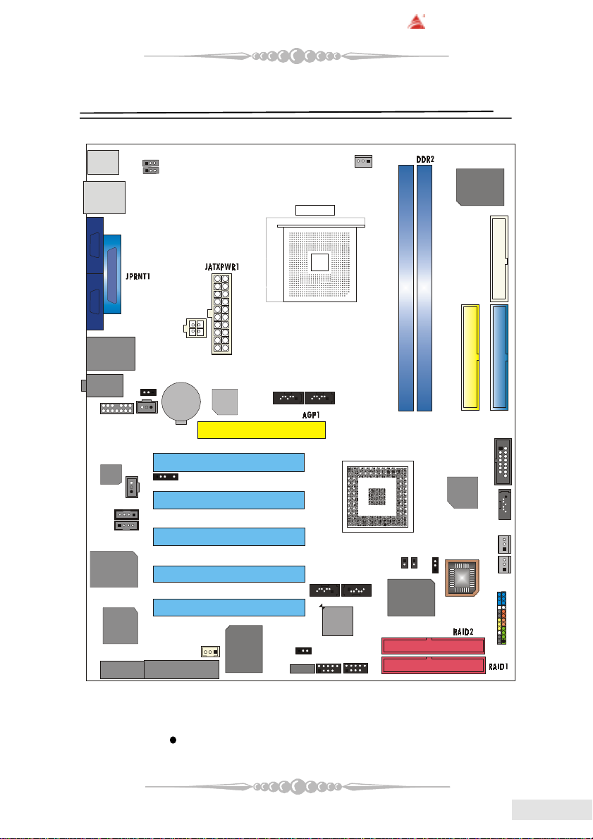
Section 1. Layout of K8NHA Pro
JCOM1
JCOM2
1
JAUDIO1
CODEC
1
8100 S
Realtek
RTL8180
JWIRELESS1
JKBMS1
1JKBMSV1
1
JUSBV1
J1394_USB1
JUSBLAN1
JAUDIO
JUSBV2
14
1
JSPDIF_IN
1
JSPDIF_OUT
1
JCDIN1
1
JCDIN2
1
1
CNR1
JATXPWR2
BAT1
JDJ1
JWOL1
RTL
8201BL
1
VT 6307
JSATA5
PCI1
PCI2
PCI3
PCI4
PCI5
J1394A1
Socket 754
JSATA4
11
JSATA2
1
VT 6420
JUSBV3
1
JUSB1
1
JCFAN1
CPU1
JSATA1
1
JUSB2
1
1
NVIDIA CK 8
DDR1
1
JCI1
VIA
VT6410
J3
JCMOS1
1
Super I/O
IT8712F
FDD1
IDE1
IDE2
1
JGAME1
15
SATA
1
Bridge
JSATA3
JSFAN1
1
BIOS
JPANEL1
1
JSFAN2
24
2
23
1
1
NOTE: “ ” represents the first pin.
55
5
55
EnglishEnglish
English
EnglishEnglish
Page 6
BIOSTAR Motherboard
BIOS
VIA
VT 6410
N V ID IA CK 8
1
VT 6307
VT 6420
SATA
B rid g e
Super I/O
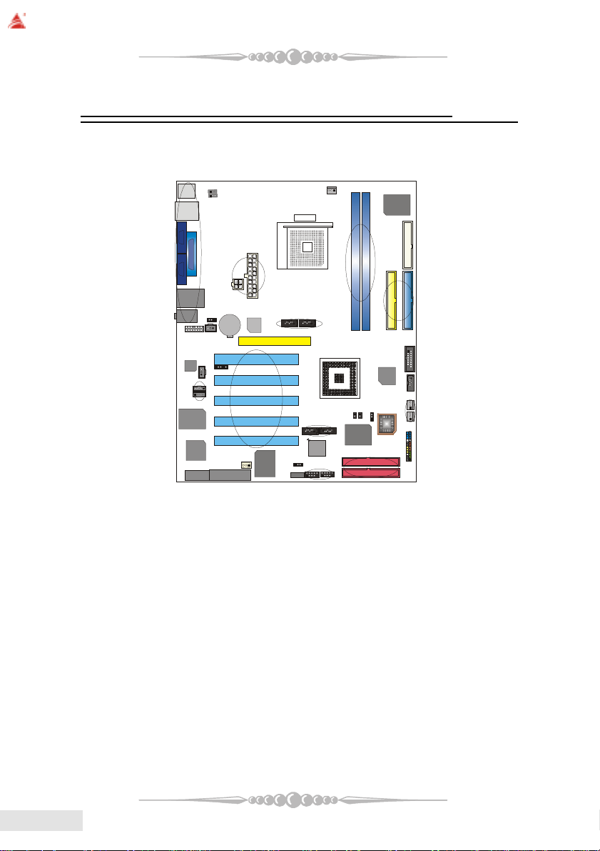
Section 2. Component Index
This section helps you to locate the components in the motherboard and to find
the details about them easily according to the mentioned pages.
B
C
Socket 754
F1
CPU1
IT8712F
A
D
E
1
F
J
CODEC
R T L
8201BL
BAT1
G
K
H
I
LM
V
T
R ealtek
RTL8180
N
A Back Panel Connectors (p. 19) B JKBMSV1: 5V/5VSB Selection for Keyboard/Mouse (p. 17)
C JUSBV1: 5V/5VSB Selection for J1394_USB1 (p. 16) D JATXPWR1-2: A TX Power Connector (p. 18)
E JUSBV2: 5V/5VSB Selection for JUSBLAN1 (p. 16) F JAUDIO1: Front Audio Header (p. 19)
G JSPDIF_IN: Digital Audio Connector (p. 18) H JSATA4-5: Serial A T A Connectors (p. 15)
I AGP1: Accelerated Graphics Port Slot (p. 14) J JSPDIF_OUT: Digital Audio Connector (p. 18)
K JDJ1: Audio DJ Connector (p. 19) L PCI1-5: Peripheral Component Interconnect Slots (p. 14)
M JCDIN1-2: CD-Rom Audio-In Header s (p. 17) N JWIRELESS1: Wireless LAN Slot (p. 13)
O CNR1: Communication Network Riser Slot (p. 14) P JWOL1: Wake On LAN Header (p. 16)
Q JUSBV3: 5V/5VSB Selection for JUSB1/2 (p. 16) R J1394A1: Front 1394A Header (p. 18)
S JUSB1-2: Front USB Headers (p. 15) T JSAT A1-2: Serial A TA Connectors (p. 15)
U RAID1-2: IDE-RAID Connectors (p. 15) V JCI1: Case Open Connector (p. 16)
W J3: Flash Rom Read/Write Enable (optional) (p. 19) X JCMOS1: Clear CMOS Jumper (p. 15)
Y JPANEL1: Front Panel Connector (p. 17) Z JSFAN1-2: System Fan Header (p. 13)
A1 JSA TA3: Serial A T A Connectors (p. 15) B1 JGAME1: Game Header (p. 16)
C1 IDE1-2: Hard Disk Connectors (p. 14) D1 DDR1-2: DDR DIMM Modules (p. 8)
E1 FDD1: Floppy Disk Connector (p. 14) F1 JCFAN1: CPU Fan Connector (p. 12)
P
O
Q
S
R
E1
C1
D1
B1
A1
X
W
Z
Y
U
EnglishEnglish
English
EnglishEnglish
66
6
66
Page 7

BIOSTAR Motherboard
Section 3. K8NHA Pro Features
In this section, you shall find all the information about the
motherboard in your computer, including its features, layout,
component index, various jumpers, headers, connectors, and also
the installation guide to help you a quick and correct installation
of your system.
A. Hardware
CPUCPU
CPU
CPUCPU
* Supports Socket 754.
* Supports the AMD Athlon 64
* Running at 200/400/600/800 MHz Front Side Bus.
ChipsetChipset
Chipset
ChipsetChipset
* NVIDIA® CrushK8
- HyperTransport link to the AMD K8 CPU.
- Supports AGP3.0 8X interface.
- Running at 200/400/600/800 MHz Front Side Bus.
- Single USB 2.0 EHCI/Dual USB 1.1 OHCI, 6 ports.
- Fast ATA/133 IDE controllers.
- PCI 2.3 interface supporting.
- Supports system and power management.
- AC’97 2.1 interface.
®
Socket-754 processor start from 3200+/2.0GHz.
Super I/OSuper I/O
Super I/O
Super I/OSuper I/O
* Chip: ITE IT8712F.
* Low Pin Count Interface.
* Provides the most commonly used legacy Super I/O functionality.
* Environment Control initiatives,
- H/W Monitor
- Fan Speed Controller
- ITE's “Smart Guardian” function
SlotsSlots
Slots
SlotsSlots
* Five 32-bit PCI bus master slots.
* One AGP 4X/8X slot.
* One CNR slot.
* One wireless LAN slot. (optional)
77
7
77
EnglishEnglish
English
EnglishEnglish
Page 8

BIOSTAR Motherboard
Main MemoryMain Memory
Main Memory
Main MemoryMain Memory
* Supports up to two DDR devices.
* Supports 200/266/333/400 MHz (with ECC) DDR devices.
* Maximum memory size is 2GB.
Total Memory Size with Unbuffered DIMMs
1RDD
2RDD
On Board IDEOn Board IDE
On Board IDE
On Board IDEOn Board IDE
* Supports four IDE disk drives.
* Supports PIO Mode 5, Bride Mode and Ultra DMA 33/66/100/133 Bus Master
Mode.
* Supports 1 Serial ATA (SATA) ports. (optional: when using SATA Bridge)
- Compliant with SATA 1.0 specification
- Data transfer rates up to 150 MB/s
tekcoSMMID
noitacoL
eludoMRDD
-1/BM215/BM652/BM821/BM46
1*BG
-1/BM215/BM652/BM821/BM46
1*BG
eziSyromeMlatoT
)BM(
BG2sixaM
EnglishEnglish
English
EnglishEnglish
1394 Chip (1394 Chip (
1394 Chip (
1394 Chip (1394 Chip (
* Chip: VIA VT6307.
* Supports 2 ports with transfer up to 400Mb/s.
LAN Chip (LAN Chip (
LAN Chip (
LAN Chip (LAN Chip (
* Chip: Realtek RTL8110S/8100C.
* Support 10 Mb/s, 100 Mb/s and 1000Mb/s auto-negotiation operation.
* Half/Full duplex capability.
* Supports ACPI, PCI power management.
LAN PHY (LAN PHY (
LAN PHY (
LAN PHY (LAN PHY (
* Chip: Realtek RTL8201BL.
* Supports 10/100 Mb/s operation.
* Half/Full duplex operation.
* Supports MII interface.
Wireless LAN - Air LinkWireless LAN - Air Link
Wireless LAN - Air Link
Wireless LAN - Air LinkWireless LAN - Air Link
* Chip: RTL8180
88
8
88
optionaloptional
optional
optionaloptional
optionaloptional
optional
optionaloptional
optionaloptional
optional
optionaloptional
))
)
))
))
)
))
))
)
))
TMTM
TM
TMTM
( (
optionaloptional
(
optional
( (
optionaloptional
))
)
))
Page 9

BIOSTAR Motherboard
* Full compliance with IEEE802.11 and IEEE802.11b specifications.
* Supports Advanced Configuration Power management Interface.(ACPI) and
PCI power management system for modern operating systems.
* Supports remote wake-up in both ACPI and APM environments.
* Keeps network maintenance costs low and eliminates usage barriers.
* Uses one RF card for Wireless LAN.
Serial ATA/RAID (Serial ATA/RAID (
Serial ATA/RAID (
Serial ATA/RAID (Serial ATA/RAID (
* Chips: VT6420
* Supports RAID 0, 1, 0+1.
* Supports one single/dual-channel ATA-133/ATA-150 interface.
* Supports 2 Serial ATA (SATA) ports.
- Compliant with SATA 1.0 specification.
- Data transfer rates up to 150 Mb/s.
Serial ATA Bridge (Serial ATA Bridge (
Serial ATA Bridge (
Serial ATA Bridge (Serial ATA Bridge (
* Chips: 88I8030 Serial ATA Bridge
* Supports both host and device operation.
* Selectable maximum speeds of 66/100/133/150 Mb/s.
* Ultra low power consumption.
* Employs teh latest SATA transceiver (PHY) technology.
* Supports SSC.
On Board ACOn Board AC
On Board AC’
On Board ACOn Board AC
* Chip: ALC650/CMI9761.
* Compliant with AC’97 specification.
* AC’97 2.2 interface.
* Supports S/PDIF-In (optional), S/PDIF-Out.
* Supports 6 channels.
On Board PeripheralsOn Board Peripherals
On Board Peripherals
On Board PeripheralsOn Board Peripherals
a. Rear side
- 2 x serial ports. (COM1/COM2)
- 1 x Parallel Port
- Supports Audio ports in vertical.
- 1 x RJ-45 LAN jack.
- Supports PS/2 mouse and PS/2 keyboard.
- Supports 4 USB2.0 ports.
- 1 x IEEE 1394A connector
optionaloptional
optional
optionaloptional
optionaloptional
optional
optionaloptional
97 Sound Codec97 Sound Codec
97 Sound Codec
97 Sound Codec97 Sound Codec
))
)
))
))
)
))
99
9
99
EnglishEnglish
English
EnglishEnglish
Page 10

BIOSTAR Motherboard
b. Front Side
- Supports 1 floppy port supports 2 FDDs with 360K, 720K, 1.2M, 1.44M
and 2.88Mbytes.
- Supports 1 IEEE1394A port.
- Supports 2 USB2.0 ports.
- 1 x game port (optional)
- Supports 1 S/PDIF-Out and 1 S/PDIF-In connector (optional).
B. BIOS & Software
BIOSBIOS
BIOS
BIOSBIOS
* A ward legal BIOS.
* Supports APM1.2.
* Supports ACPI.
* Supports USB Function.
* The setup procedures can be found in the Setup Driver CD.
SoftwareSoftware
Software
SoftwareSoftware
* Supports WarpspeederTM, 9th TouchTM, FLASHERTM, WatchdogTM,
WinFlasher
* Offers the highest performance for Windows 98 SE, Windows 2000, Windows
Me, Windows XP, Linux, etc.
TM
and StudioFun!
EnglishEnglish
English
EnglishEnglish
1010
10
1010
Page 11

BIOSTAR Motherboard
Section 4. Package contents
Check what you have bought before you start your DIY action.
If there are anything missing, please contact your dealer
immediately.
* HDD Cable X 1
* FDD Cable X 1
* User's Manual X1
* USB 2.0 Cable X1 (optional)
* Rear I/O Panel for ATX Case X1 (optional)
* Fully Setup Driver CD X1
* StudioFun! Application CD X1 (optional)
* S/PDIF Cable X 1 (optional)
* Serial ATA Cable X 2 ( optional)
1111
11
1111
EnglishEnglish
English
EnglishEnglish
Page 12
BIOSTAR Motherboard
1
Section 5. Installation and Setup
In this section, you will learn how to install the CPU, DDR
Module, and also how to set up jumpers and all the information
about the components on the motherboard. Not only can you find
the installation steps, but also the details and locations of the
components on the motherboard.
1. CPU Installation1. CPU Installation
1. CPU Installation
1. CPU Installation1. CPU Installation
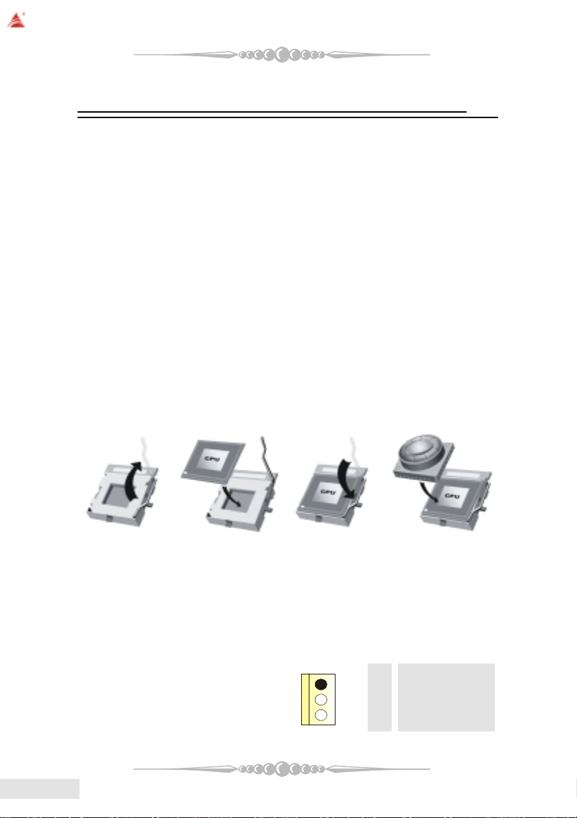
The motherboard supports the AMD Athlon 64® Socket-754 processor. When
you are installing the CPU, make sure the CPU has a cooling fan attached on the right
to prevent overheating. If you do not find the cooling fan, contact your dealer and make
sure to install them before turning on the computer.
Step1: Pull the lever sideways away from the socket and then raise the
lever up to a 90-degree angle.
Step2: Look for the white dot/cut edge. The white dot/cut edge should
point towards the lever pivot. The CPU will fit only in the correct orientation.
Step3: Hold the CPU down firmly, and then close the lever.
Step4: Put the CPU fan on the CPU and buckle it. Connect the CPU fan
power cable to the JCFAN1. This completes the installation.
EnglishEnglish
English
EnglishEnglish
Step 1 Step 2 Step 3 Step 4
2 Central Processing Unit: CPU2 Central Processing Unit: CPU
2 Central Processing Unit: CPU
2 Central Processing Unit: CPU2 Central Processing Unit: CPU
These fan headers support cooling fans built in the computer. Orient the fans to
make the heat sink fins to allow air flow to go across the onboard heat sinks instead of
the expansion slots. The fan wiring and plug may be different according to the fan
manufacturer. Connect the fan fable to the connector while matching the black wire to
the ground pin.
1212
12
1212
(1) CPU Fan Headers: JCFAN1
Pin Assignment
1 Ground
2 +12V
3 FAN RPM Sense
Page 13
(2) System Fan Headers: JSFAN1/JSFAN2 (optional)
1
Pin Assignment
1 Ground
2 +12V
3 FAN RPM Sense
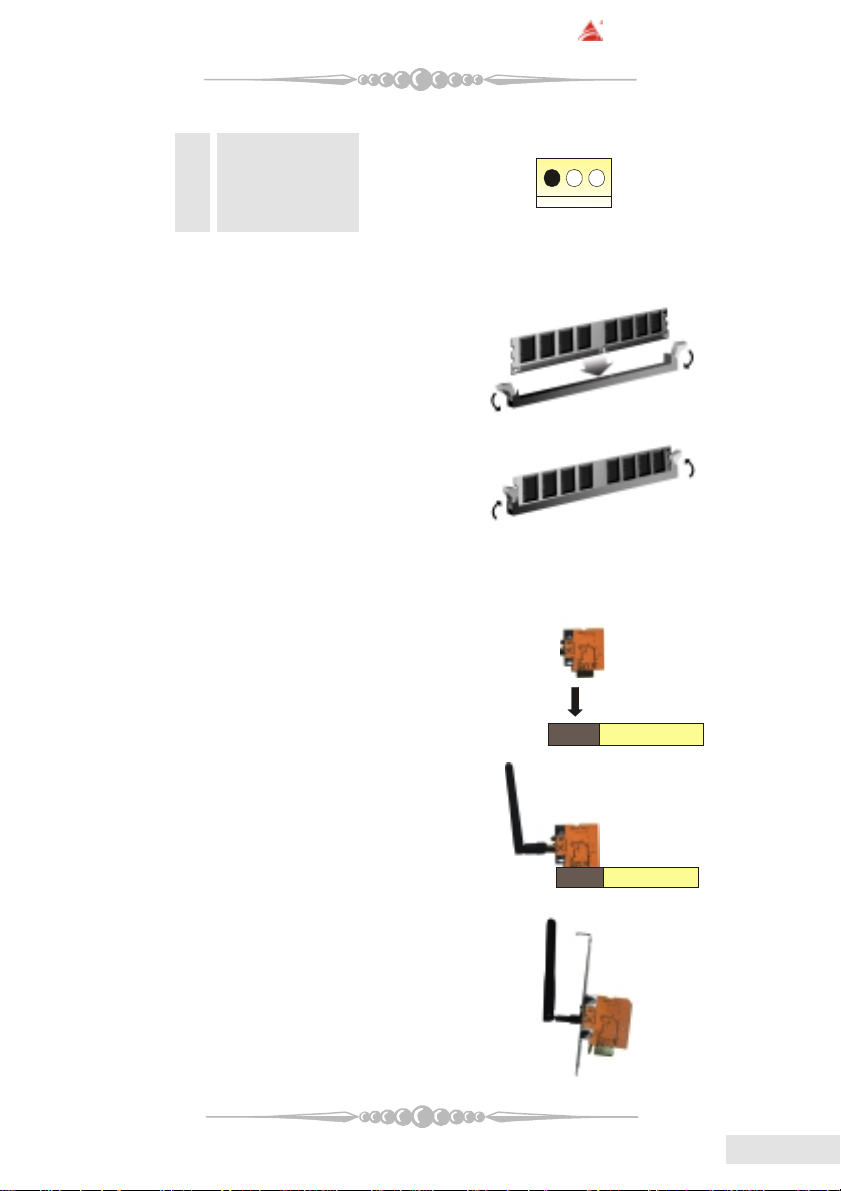
3. Installing DDR Module3. Installing DDR Module
3. Installing DDR Module
3. Installing DDR Module3. Installing DDR Module
1. Unlock a DIMM slot by
pressing the retaining clips
outward. Align a DIMM on the
slot such that the notch on the
DIMM matches the break on
the slot.
2. Insert the DIMM firmly and
vertically into the slot until the
retaining chip snap back in place
and the Dimm is properly
seated.
BIOSTAR Motherboard
6. Wireless LAN Card Installation (6. Wireless LAN Card Installation (
6. Wireless LAN Card Installation (
6. Wireless LAN Card Installation (6. Wireless LAN Card Installation (
1. Align the wireless LAN on the slot
such a way that wireless LAN card
matches in the slot. Be sure to face
the wireless LAN card with its components towards the inner part of the
motherboard.
2. Insert the wireless LAN card vertically and firmly into the slot till the
wireless card is properly seated.
3. Screw the brackets.
4. Insert the wireless LAN antenna by
turning it clockwise.
optionaloptional
optional
optionaloptional
))
)
))
1313
13
1313
EnglishEnglish
English
EnglishEnglish
Page 14
BIOSTAR Motherboard
7. How to set up Jumpers?7. How to set up Jumpers?
7. How to set up Jumpers?
7. How to set up Jumpers?7. How to set up Jumpers?
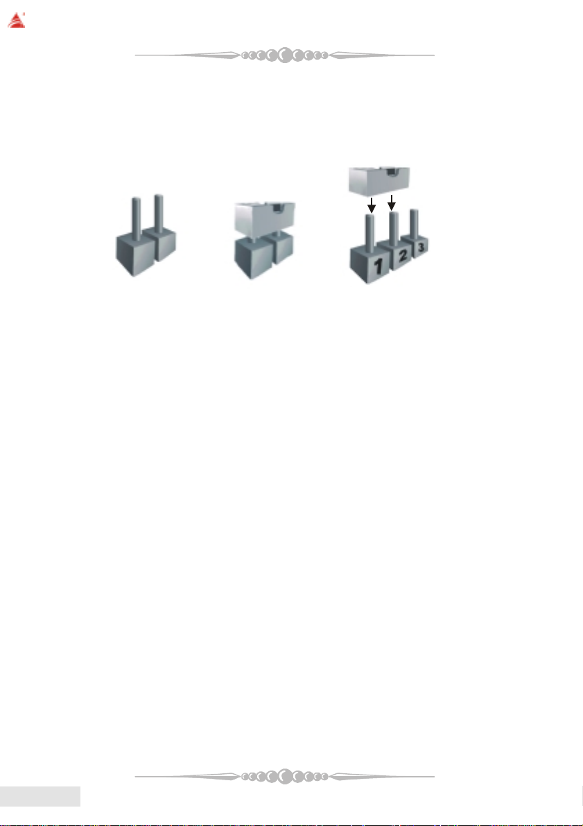
The illustration shows how to set up jumpers. When the Jumper cap is placed
on pins, the jumper is “close”. IF no jumper cap is placed on the pins, the jumper is
”open”. The illustration shows a 3-pin jumper whose pin1and 2 are “close” when
jumper cap is placed on these 2 pins.
Jumper open Jumper close Pin1-2 close
8. Jumpers, Headers, Connectors & Slots:8. Jumpers, Headers, Connectors & Slots:
8. Jumpers, Headers, Connectors & Slots:
8. Jumpers, Headers, Connectors & Slots:8. Jumpers, Headers, Connectors & Slots:
(1) Floppy Disk Connector: FDD1
The motherboard provides a standard floppy disk connector that supports
360K, 720K, 1.2M, 1.44M and 2.88M floppy disk types. This connector
supports the provided floppy drive ribbon cables.
(2) Hard Disk Connectors: IDE1/ IDE2
The motherboard has a 32-bit Enhanced PCI IDE Controller that provides PIO
Mode 0~4, Bus Master, and Ultra DMA 33/ 66/ 100/ 133 functionality. It has
two HDD connectors IDE1 (primary) and IDE2 (secondary).
The IDE connectors can connect a master and a slave drive, so you can connect
up to four hard disk drives. The first hard drive should always be connected to
IDE1.
(3) Peripheral Component Interconnect Slots: PCI1-5
This motherboard is equipped with 5 standard PCI slots. PCI stands for Pe-
ripheral Component Interconnect, and it is a bus standard for expansion cards.
This PCI slot is designed as 32 bits.
(4) Accelerated Graphics Port Slot: AGP1
Your monitor will attach directly to that video card. This motherboard sup-
ports video cards for PCI slots, but it is also equipped with an Accelerated
Graphics Port (AGP). An AGP card will take advantage of AGP technology to
improve video efficiency and performance, especially with 3D graphics.
EnglishEnglish
English
EnglishEnglish
1414
14
1414
(5) Communication Network Riser Slot: CNR1
The CNR specification is an open Industry Standard Architecture, and it de-
fines a hardware scalable riser card interface, which supports modem only.
Page 15
BIOSTAR Motherboard
2
1
(6) Serial ATA Connector: JSATA1/JSATA2/JSATA3/JSATA4/JSATA5
(optional)
The motherboard has a PCI to SAT A Controller with 2 channels ST AT interface.
It satisfies the SATA 1.0 spec and can transfer data with 1.5GHz speed.
Pin Assignment Pin Assignment
1 Ground 2 TX+
3 TX- 4 Ground
5 RX- 6 RX+
7 Ground
(7) IDE-Raid Connector: RAID1/2 (optional)
This connector supports RAID0 or RAID1 or RAID 0+1 configuration through
the onboard Parallel ATA (VT6410) controller chip. You can use the IDE
feature to set up a disk array configuration and to support additional IDE
devices. However, it can only support master mode IDE HDD.
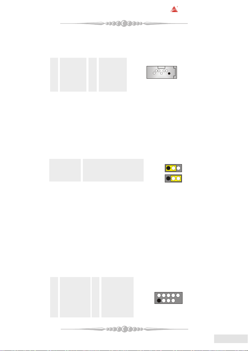
(8) Clear CMOS Jumper: JCMOS1
This jumper helps you to clear the Real Time Clock (R TC) Ram in CMOS. You
can erase the CMOS RTC Ram data to clear the CMOS memory of date, time,
and system setup parameters.
JCMOS1 Assignment
Pin 1-2 Close Normal Operation (default)
Pin 2-3 Close Clear CMOS Data
* Clear CMOS Procedures:
1. Remove AC power line.
2. Set the jumper to "Pin 2-3 Close".
3. Wait for five seconds.
4. Set the jumper to "Pin 1-2 Close".
5. Power on the AC.
6. Reset your desired password or clear the CMOS data.
1234567
1
1
(9) Front USB Header: JUSB1/ (JUSB2: optional)
The motherboard provides two USB 2.0 Pin Header. USB 2.0 technology
increases Data transfer rate up to a maximum throughput of 480 Mbps, which
is 40 times faster than USB 1.1, and is ideal for connecting high-speed USB
interface peripherals such as USB HDD, digital cameras, MP3 players, printers,
modems, etc.
Pin Assignment Pin Assignment
1 +5V(fused) 2 +5V(fused)
3 USBP-0/(-6) 4 USBP-1/(-7)
5 USBP+0/(+6) 6 USBP+1/(+7)
7 Ground 8 Ground
9 KEY 10 NC
1515
15
1515
EnglishEnglish
English
EnglishEnglish
Page 16
BIOSTAR Motherboard
(10) Power Source Selection for USB: JUSBV1/JUSBV2/JUSBV3 (optional)
JUSBV1/JUSBV2 Assignment Description
JUSBV3
Pin 1-2 close +5V JUSBV1: 5V for J1394_USB1
1 3
Pin 2-3 close +5V Standby Voltage 5V standby to power on.
JUSBV2: 5V for JUSBLAN1
JUSBV3: 5V for JUSB1 ports
1
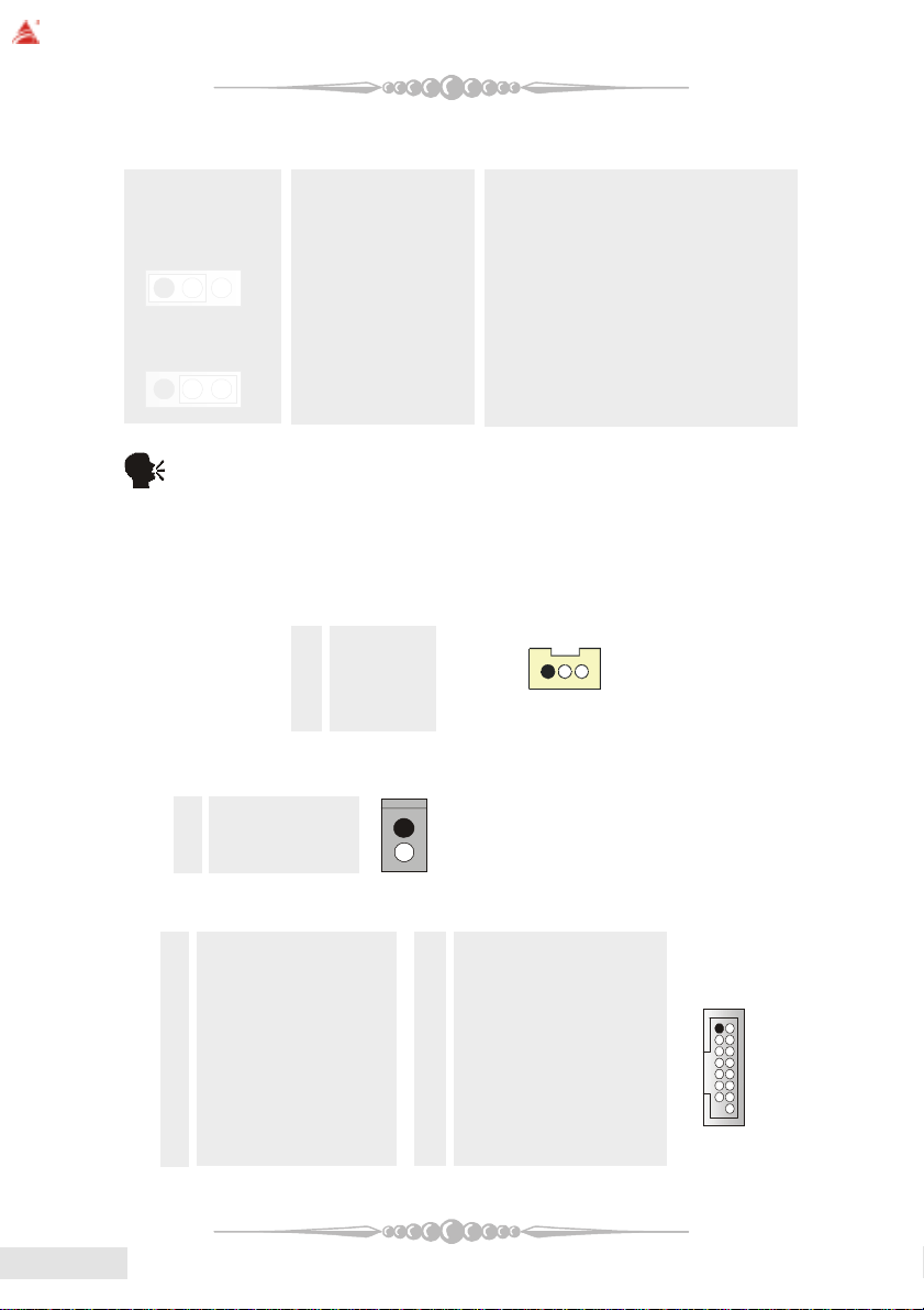
(11) Wake On LAN Header: JWOL1 (optional)
(12) Case Open Connector: JCI1 (optional)
Pin Assignment
1 Ground
2 Case Open Signal
(13) Game Header: JGAME1 (optional)
Pin Assignment Pin Assignment
1 +5V 2 +5V
3 Joystick B Button 1 4 Joystick A Button 1
5 Joystick B Coordinate X 6 Joystick A Coordinate X
7 MIDI Output 8 Ground
9 Joystick B Coordinate Y 10 Ground
11 Joystick B Button 2 12 Joystick A Coordinate Y
13 MIDI Input 14 Joystick A Button 2
15 NA 16 +5V
3
Note: In order to power-on USB devices function, "JUSBV1/JUSBV2/
JUSBV3" jumper cap should be placed on pin 2-3 respectively.
This connector allows you to connect to a LAN card with Wake On LAN
function. Y ou can wake up the computer by remote control through a local area
network.
Pin Assignment
1 +5V_SB
2 Ground
3 W ake up
1
1
JWOL1
12
EnglishEnglish
English
EnglishEnglish
1616
16
1616
Page 17
BIOSTAR Motherboard
1
1
JCDIN1/JCDIN2
PWR_LED
HLED
24
23
IR
(14) CD-ROM Audio-In Header: JCDIN1/JCDIN2
This header allows you to receive stereo audio input from sound sources, such
as CD-ROM, TV Tuner, MPEG card, etc.
Pin Assignment
1 Left Channel Input
2 Ground
3 Ground
4 Right Channel Input
(15) Front Panel Connector: JPANEL1
The connector is for electrical connection to the front panel switches and
LEDs.
Pin Assignment Function Pin Assignment Function
1 +5V Speaker 2 Sleep Control SleepButton
3 NA Connector 4 Ground
5 NA 6 NA NA
7 Speaker 8 Power LED (+) POWER LED
9 HDD LED (+) Hard DriveLED 10 Power LED (+)
11 HDD LED (-) 12 Power LED (-)
13 Ground ResetButton 14 Power Button Power-on Button
15 Reset Control 16 Ground
17 NA 18 KEY
19 NA IrDA 20 KEY IrDA
21 +5V Connector 22 Ground Connector
23 IRTX 24 IRRX
SLP
(+)
2
1
SPK
(+)
ON/OFF
(-)(+)
(-)
RST
IR
(16) 5V / 5VSB Selection for KB: JKBMSV1 (optional)
JKBMSV1 Assignment Description
Pin 1-2 close +5V 5V for keyboard and mouse
Pin 2-3 close +5V_SB 5V standby for keyboard and
mouse to power on your system
1
1717
17
1717
EnglishEnglish
English
EnglishEnglish
Page 18
BIOSTAR Motherboard
1
123
4
1
0
2
10
1
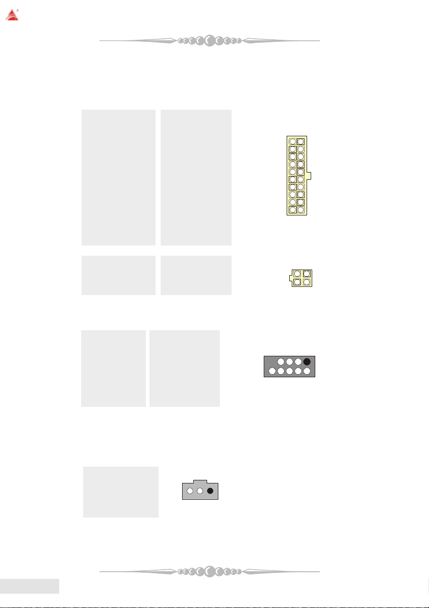
(17) Power Connectors: JATXPWER1/ JATXPWR2
The motherboard supports ATX power supply for the power system. Before
installing the power supply connector, please make sure that all components are
installed properly.
PIN Assignment PIN Assignment
1 +3.3V 11 +3.3V
2 +3.3V 12 -12V
3 Ground 13 Ground
4 +5V 14 PS_ON
5 Ground 15 Ground
6 +5V 16 Ground
7 Ground 17 Ground
8 PW_OK 18 -5V
9 +5V_SB 19 +5V
10 +12V 20 +5V
PIN Assignment PIN Assignment
1 +12V 3 Ground
2 +12V 4 Ground
(18) Front 1394 Header: J1394A1 (optional)
10
2
1
1
EnglishEnglish
English
EnglishEnglish
Pin Assignment Pin Assignment
1 A1+ 2 A13 Ground 4 Ground
5 B1+ 6 B17 +12V 8 +12V
9 KEY 10 NA
(19) Digital Audio Connector: JSPDIF_OUT/(JSPDIF_IN:optional)
The connector is used to connect SPDIF (Sony & Philips Digital Interconnect
Format) interface for digital audio transmission.
Pin Assignment
1 +5V
2 SPDIF_OUT
3 Ground
9
1818
18
1818
Page 19

(20) Front Panel Audio Header: JAUDIO1
14
13
1
1
The connector allows you to connect to the front panel audio.
Pin Assignment Pin Assignment
1 Mic In 2 Ground
3 Mic Power 4 Audio Power
5 RT Line Out 6 RT Line Out
7 Reserved 8 Key
9 LFT Line Out 10 LFT Line Out
11 RT Line In 12 RT Line In
13 LFT Line In 14 LFT Line In
(21) Flash ROM READ/WRITE Enable : J3 (optional)
J3 Assignment
Pin1-2 open Enable the flash Rom to read and write.
Pin 1-2 close Disable the flash Rom to read and write.
(22) AUDIO DJ Connector: JDJ1 (optional)
BIOSTAR Motherboard
2
1
Pin Assignment Pin Assignment
1 SMBDATA 2 SMBCLK
3 INT_B 4 KEY
5 ATX_PWROK
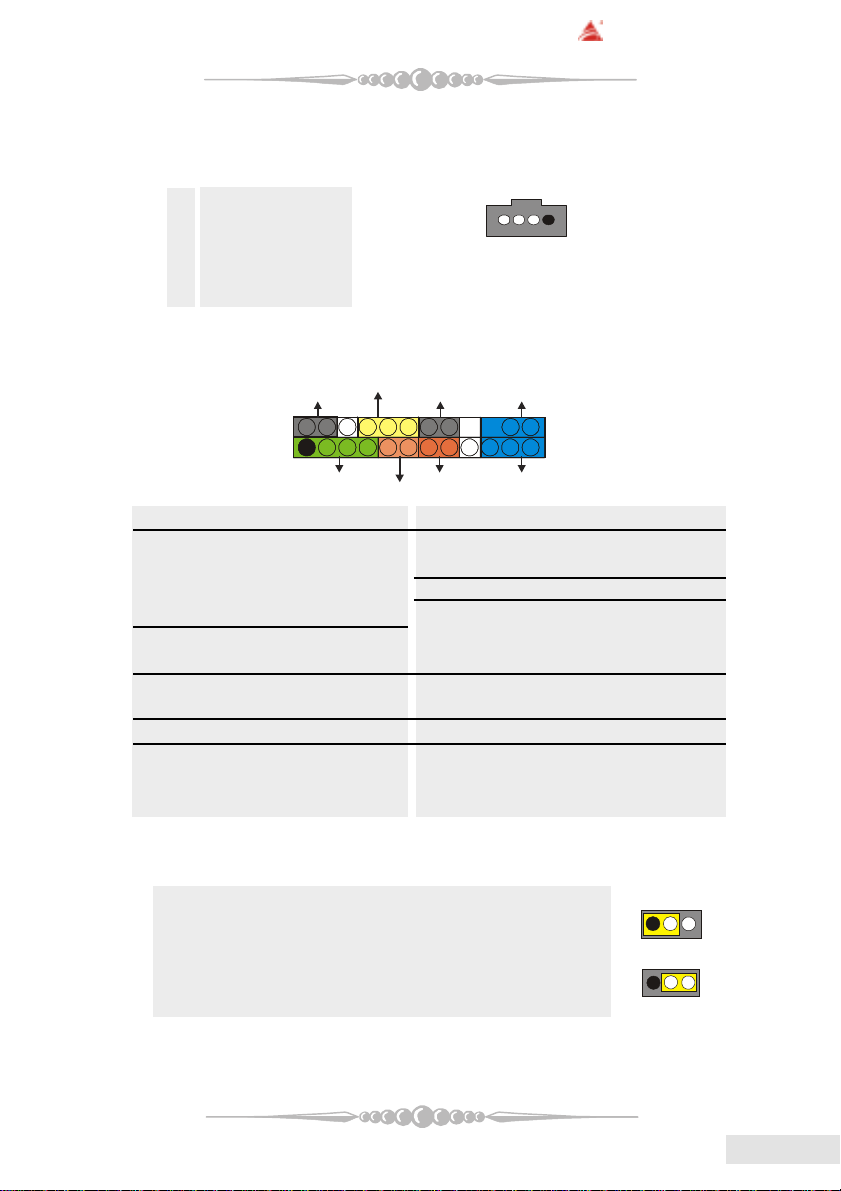
(23) Back Panel Connectors
5
1919
19
1919
EnglishEnglish
English
EnglishEnglish
Page 20

BIOSTAR Motherboard
6 Channel Speakers
Speaker Out
Line In/ Rear Speaker
Mic In/ Center & Bass
EnglishEnglish
English
EnglishEnglish
2020
20
2020
Page 21

Section 6. Trouble Shooting
BIOSTAR Motherboard
PROBABLE
No power to the system at all; power light
doesn't illuminate; fan inside power supply
does not turn on. Indicator light on keyboard
does not turn on.
System inoperative. Keyboard lights are on,
power indicator lights are lit, and hard drive
is spinning.
System does not boot from hard disk drive,
but it can be booted from CD-ROM drive.
System only boots from CD-ROM. Hard
disk can be read and applications can be
used but booting from hard disk is
impossible.
Screen message says "Invalid
Configuration" or "CMOS Failure."
SOLUTION
* Make sure power cable is securely
plugged in.* Replace cable.
* Contact technical support.
* Using even pressure on both ends of
the DIMM, press down firmly until the
module snaps back in places.
* Check cable running from disk to disk
controller board. Make sure both ends
are securely plugged in; check the drive
type in the standard CMOS setup.
* Backing up the hard drive is extremely
important. All hard disks are capable
of breaking down at any time.
* Back up data and applications files.
Reformat the hard drive. Re-install
applications and data using backup
disks.
* Review system's equipment. Make sure
correct information is in setup.
Cannot boot system after installing second
hard drive.
Error message reading "SECTOR NOT
FOUND" or other error messages not
allowing certain data to be retrieved.
* Set master/slave jumpers correctly.
* Run SETUP program and select correct
drive types. Call drive manufacturers
for compatibility with other drives.
* Back up any salvageable data. Then,
low-level format, partition, and highlevel format the hard drive. Re-install
all saved data when completed.
2121
21
2121
EnglishEnglish
English
EnglishEnglish
Page 22

BIOSTAR Motherboard
PROBABLE
Scree is blank.
Screen goes blank periodically.
Memory problem.
Computer virus.
Keyboard failure.
No display on screen.
C: drive failure.
Missing operating system on hard drive.
Certain keys do not function.
SOLUTION
* Check the power connectors to monitor
and to system. Make sure monitor is
connected to display card.
* Disable screen saver.
* Reboot computer. Reinstall memory,
and make sure that all memory modules
are installed in correct sockets.
* Use anti-virus programs to detect and
clean viruses.
* Reconnect keyborad. Check keys
again. If no improvement, replace
keyboard.
* If possible, connect monitor to another
system. If no color still, replace
monitor.
* Check hard drive cable.
* Run setup and select correct drive type.
* Replace keyboard.
EnglishEnglish
English
EnglishEnglish
Keyboard is locked, no keys function.
2222
22
2222
* Unlock keyboard.
Page 23

BIOSTAR Motherboard
WarpSpeeder
TM
Introduction
[ W arpSpeederTM ], a new powerful control utility, features three user-friendly
functions including Overclock Manager, Overvoltage Manager, and Hardware Monitor.
With the Overclock Manager, users can easily adjust the frequency they prefer
or they can get the best CPU performance with just one click. The Overvoltage Manager,
on the other hand, helps to power up CPU core voltage and Memory voltage. The cool
Hardware Monitor smartly indicates the temperatures, voltage and CPU fan speed as
well as the chipset information. Also, in the About panel, you can get detail descriptions
about BIOS model and chipsets. In addition, the frequency status of CPU, memory,
AGP and PCI along with the CPU speed are synchronically shown on our main panel.
Moreover, to protect users' computer systems if the setting is not appropriate
when testing and results in system fail or hang, [ W arpSpeeder
the system stability by automatically rebooting the computer and then restart to a
speed that is either the original system speed or a suitable one.
TM
] technology assures
System Requirement
OS Support: Windows 98 SE, Windows Me, Windows 2000, Windows XP
DirectX: DirectX 8.1 or above. (The Windows XP operating system includes DirectX
8.1. If you use Windows XP, you do not need to install DirectX 8.1.)
Installation
1. Execute the setup execution file, and then the following dialog will pop up.
Please click "Next" button and follow the default procedure to install.
2323
23
2323
EnglishEnglish
English
EnglishEnglish
Page 24

BIOSTAR Motherboard
2. When you see the following dialog in setup procedure, it means setup is
completed. If the "Launch the W arpSpeeder Tray Utility" checkbox is checked,
the Tray Icon utility and [WarpSpeeder
immediately launched after you click "Finish" button.
TM
] utility will be automatically and
EnglishEnglish
English
EnglishEnglish
2424
24
2424
Page 25

BIOSTAR Motherboard
Usage
The following figures are just only for reference, the screen printed in
this user manual will change according to your motherboard on hand.
[WarpSpeederTM] includes 1 tray icon and 5 panels:
1. Tray Icon:
Whenever the Tray Icon utility is launched, it will display a little tray icon on
the right side of Windows Taskbar.
This utility is responsible for conveniently invoking [WarpSpeederTM] Utility.
You can use the mouse by clicking the left button in order to invoke [WarpSpeeder
directly from the little tray icon or you can right-click the little tray icon to pop up a
popup menu as following figure. The "Launch Utility" item in the popup menu has the
same function as mouse left-click on tray icon and "Exit" item will close Tray Icon
utility if selected.
2. Main Panel
If you click the tray icon, [ W arpSpeeder
do the following figure; the utility's first window you will see is Main Panel.
Main Panel contains features as follows:
a. Display the CPU Speed, CPU external clock, Memory clock, AGP clock,
and PCI clock information.
b. Contains About, Voltage, Overclock, and Hardware Monitor Buttons for
invoking respective panels.
TM
] utility will be invoked. Please refer
TM
]
2525
25
2525
EnglishEnglish
English
EnglishEnglish
Page 26

BIOSTAR Motherboard
c. With a user-friendly Status Animation, it can represent 3 overclock percentage
stages:
Duck walking => overclock percentage from 100% ~ 110 %
Duck running => overclock percentage from 110% ~ 120%
Duck burning => overclock percentage from 120% ~ above
EnglishEnglish
English
EnglishEnglish
3. Voltage Panel
Click the Voltage button in Main Panel, the button will be highlighted and the
Voltage Panel will slide out to up as the following figure.
In this panel, you can decide to increase CPU core voltage and Memory voltage
or not. The default setting is "No". If you want to get the best performance of
overclocking, we recommend you click the option "Yes".
2626
26
2626
Page 27

BIOSTAR Motherboard
4. Overclock Panel
Click the Overclock button in Main Panel, the button will be highlighted and
the Overclock Panel will slide out to left as the following figure.
Overclock Panel contains these features:
2727
27
2727
EnglishEnglish
English
EnglishEnglish
Page 28

BIOSTAR Motherboard
a. "-3MHz button", "-1MHz button", "+1MHz button", and "+3MHz button":
provide user the ability to do real-time overclock adjustment.
Warning: Manually overclock is potentially dangerous, especially when
the overclocking percentage is over 110 %. We strongly recommend you
verify every speed you overclock by click the Verify button. Or, you can
just click Auto overclock button and let [ WarpSpeeder
gets the best result for you.
b. "Recovery Dialog button": Pop up the following dialog. Let user select a
restoring way if system need to do a fail-safe reboot.
TM
] automatically
EnglishEnglish
English
EnglishEnglish
c. "Auto-overclock button": User can click this button and [ W arpSpeeder
will set the best and stable performance and frequency automatically. [WarpSpeederTM]
utility will execute a series of testing until system fail. Then system will do fail-safe
reboot by using Watchdog function. After reboot, the [ WarpSpeeder
restore to the hardware default setting or load the verified best and stable frequency
according to the Recovery Dialog's setting.
d. "Verify button": User can click this button and [ WarpSpeeder
proceed a testing for current frequency. If the testing is ok, then the current frequency
will be saved into system registry. If the testing fail, system will do a fail-safe rebooting.
After reboot, the [ WarpSpeeder
or load the verified best and stable frequency according to the Recovery Dialog's setting.
Note: Because the testing programs, invoked in Auto-overclock and Verify, include
DirectDraw, Direct3D and DirectShow tests, the DirectX 8.1 or newer runtime
library is required. And please make sure your display card's color depth is High
color (16 bit) or True color( 24/32 bit ) that is required for Direct3D rendering.
2828
28
2828
TM
] utility will restore to the hardware default setting
TM
] utility will
TM
TM
] will
]
Page 29

BIOSTAR Motherboard
5. Hardware Monitor Panel
Click the Hardware Monitor button in Main Panel, the button will be highlighted and the Hardware Monitor panel will slide out to left as the following figure.
In this panel, you can get the real-time status information of your system. The information
will be refreshed every 1 second.
6. About Panel
Click the About button in Main Panel, the button will be highlighted and the
About Panel will slide out to up as the following figure.
In this panel, you can get model name and detail information in hints of all the chipset
that are related to overclocking. Y ou can also get the mainboard's BIOS model and the
Version number of [ WarpSpeeder
TM
] utility.
2929
29
2929
EnglishEnglish
English
EnglishEnglish
Page 30

BIOSTAR Motherboard
EnglishEnglish
English
EnglishEnglish
Note: Because the overclock, overvoltage, and hardware monitor features are
controlled by several separate chipset, [ W arpSpeederTM ] divide these features to
separate panels. If one chipset is not on board, the correlative button in Main
panel will be disabled, but will not interfere other panels' functions. This property
can make [ WarpSpeeder
3030
30
3030
TM
] utility more robust.
Page 31

K8NHA Pro BIOS Setup
BIOS Setup........................................................................................1
1 Main Menu.....................................................................................................3
2 Standard CMOS Features ..............................................................................6
3 Advanced BIOS Features...............................................................................9
4 Advanced Chipset Features..........................................................................12
5 Integrated Peripherals ..................................................................................16
6 Power Management Setup ...........................................................................21
7 PnP/PCI Configurations............................................................................... 24
8 PC Health Status .......................................................................................... 26
9 Voltage Control............................................................................................28
i
Page 32

BIOS Setup
Introduction
T his ma nual dis cuss ed Aw ard™ Set up progr am built into the R OM BIOS . T he Setup
program allows users to modify the basic system configuration. This special information is
th en sto red in batt ery-b ac ked RAM so tha t it retains the Setu p inf ormatio n w hen th e po we r
is turned off.
T he Awa rd BIOS™ insta lled in your compute r syst em’s ROM (Read O nly Me mory) is a
custom version of an industry standard BIOS. This means that it supports Nvidia CK8
processor input/output system. The BIOS provides critical low-level support for standard
devices such as disk drives and serial and parallel ports.
Adding important has customized the Award BIOS™, but nonstandard, features such as
virus and password protection as well as special support for detailed fine-tuning of the
chipset controlling the entire system.
The rest of this manual is intended to guide you through the process of configuring your
system using Setup.
Plug and Play Support
These AWARD BIOS supports the Plug and Play Version 1.0A specification. ESCD
(Extended System Configuration Data) write is supported.
EPA Green PC Support
This AWARD BIOS supports Version 1.03 of the EPA Green PC specification.
APM Support
These AWARD BIOS supports Version 1.1&1.2 of the Advanced Power Management
(APM) specification. Power management features are implemented via the System
Management Interrupt (SMI). Sleep and Suspend power management modes are supported.
This AWARD BIOS can manage power to the hard disk drives and video monitors.
ACPI Support
Award ACPI BIOS support Version 1.0 of Advanced Configuration and Power interface
specification (ACPI). It provides ASL code for power management and device
configuration capabilities as defined in the ACPI specification, developed by Microsoft,
Intel and Toshiba.
1
Page 33

PCI Bus Su ppo rt
This AWARD BIOS also supports Version 2.1 of the Intel PCI (Peripheral Component
Interconnect) local bus specification.
DRAM Support
DDR DRAM (Double Data Rate Synchronous DRAM) are supported.
Suppo r te d CP Us
This AWARD BIOS supports the AMD
Us i ng Setup
In general, you use the arrow keys to highlight items, press <Enter> to select, use the
<PgUp> and <PgDn> keys to change entries, press <F1> for help and press <Esc> to quit.
The following table provides more detail about how to navigate in the Setup program by
using the keyboard.
Keystroke Function
Up arro w Move to p revious item
Down arrow Move to ne xt item
Left arrow Move to the item on the left (menu bar)
Right arrow Move to the item on the right (menu bar)
Move E nter Move to t he i tem you desired
PgUp key Increase the numeric value or make changes
PgDn key Decrease the numeric value or make changes
+ Key Increase the numeric value or make changes
- Key Decrease the numeric value or make changes
Esc key Main Menu – Quit and not save changes into CMOS
F1 key Genera l help o n Set up na vigatio n ke ys
F5 key Load previous values from CMOS
F7 key Load the optimized defaults
F10 key Save all the CMOS changes and exit
®
CPU.
Status Page Setup Menu and Option Page Setup Menu – Exit
Current page and return to Main Menu
2
Page 34

1 Main Menu
Once you enter Award BIOS™ CMOS Setup Utility, the Main Menu will appear on the
screen. The Main Menu allows you to select from several setup functions. Use the arrow
keys to select among the items and press <Enter> to accept and enter the sub-menu.
0
WARNING
The information about BIOS defaults on manual (Figu re
1,2,3,4,5,6,7,8,9) is just for reference, please refer to the BIOS
installed on board, for update information.
Figure 1. Main Menu
Standard CMOS Features
This submenu contains industry standard configurable options.
Advance d BIOS Features
This submenu allows you to configure enhanced features of the BIOS.
Advanced Chipset Features
This submenu allows you to configure special chipset features.
3
Page 35

Integrated Peripherals
This submenu allows you to configure certain IDE hard drive options and Programmed
Input/ Output features.
Power Management Setup
This submenu allows you to configure the power management features.
PnP/PCI Configurations
This submenu allows you to configure certain “Plug and Play” and PCI options.
PC Health Status
This submenu allows you to monitor the hardware of your system.
Voltage Control
This submenu allows you to change CPU Vcore Voltage and CPU/ PCI clock. (Howe ver,
this function is strongly recommended not to use. Not properly change the voltage
and clock may cause CPU or M/B damage!)
Lo a d Opti mi ze d De fa ults
This selection allows you to reload the BIOS when the system is having problems
particularly with the boot sequence. These configurations are factory settings optimized
for this system. A confirmation message will be displayed before defaults are set.
Set Supervisor Password
Setting the supervisor password will prohibit everyone except the supervisor from making
changes using the CMOS Setup Utility. You will be prompted with to enter a password.
Set User Password
If the Supervisor Password is not set, then the User Password will function in the same way
as the S uper visor Pas sword. If the Supe rviso r Pa sswo rd is set and t he User P a sswor d is
set, the “User” will only be able to view configurations but will not be able to change them.
4
Page 36

Save & Exit Setup
Save all configuration changes to CMOS(memory) and exit setup. Confirmation message
will be displayed before proceeding.
Exit Without Saving
Abandon all changes made during the current session and exit setup. Confirmation message
will be displayed before proceeding.
Upgrade BIOS
This submenu allows you to upgrade bios.
5
Page 37

2 Standard CMOS Features
The items in Standard CMOS Setup Menu are divided into 10 categories. Each category
includes no, one or more than one setup items. Use the arrow keys to highlight the item and
then use the<PgUp> or <PgDn> keys to select the value you want in each item.
Figure 2. Standard CMOS Setup
6
Page 38

Main Menu Selections
This table shows the selections that you can make on the Main Menu.
Item Options Description
Date mm : dd : yy Set the system date. Note
Time hh : mm : ss Set the system internal
IDE Primary Master Options are in its sub
menu.
IDE Primary Slave Options are in its sub
menu.
IDE Secondary Master Options are in its sub
menu.
IDE Secondary Slave Options are in its sub
menu.
Drive A
Drive B
Video EGA/VGA
360K, 5.25 in
1.2M, 5.25 in
720K, 3.5 in
1.44M, 3.5 in
2.88M, 3.5 in
None
CGA 40
CGA 80
MONO
that the ‘Day’ automatically
changes when you set the
date.
clock.
Press <Enter> to enter the
sub menu of detailed
options
Press <Enter> to enter the
sub menu of detailed
options.
Press <Enter> to enter the
sub menu of detailed
options.
Press <Enter> to enter the
sub menu of detailed
options.
Select the type of flop py
disk drive installed in your
system.
Select the default video
device.
7
Page 39

Item Options Description
Halt On All Errors
No Errors
All, but Keyboard
All, but Diskette
All, but Disk/ Key
Base Memory N/A Displays the amount of
Extended Memory N/A Displays the amount of
Total Memory N/A Displays the total memory
Select the situation in which
you want the B IOS to stop
the POST process and
notify you.
conventional memory
detected during boot up.
extended memory detected
during boot up.
available in the system.
8
Page 40

3 Advanced BIOS Features
Fig ure 3. Adva nce d BIOS Se tup
Virus Warning
This option allows you to choose the VIRUS Warning feature that is used to protect the
IDE Hard Disk boot sector. If this function is enabled and an attempt is made to write to the
boot sector, BIOS will display a warning message on the screen and sound an alarm beep.
Disabled (default) Virus protection is disabled.
Enabled Virus protection is activated.
Quick Power On Self Test
Enabling this option will cause an abridged version of the Power On Self-Test (POST) to
execute after you power up the computer.
Disabled Normal POST.
Enable d (default) Enable quick POST.
Boot Up NumLock Status
Selects the NumLock. State after power on.
On (default) Numpad is number keys.
Off Numpad is arrow keys.
9
Page 41

Typematic Rate Se tting
When a key is held down, the keystroke will repeat at a rate determined by the keyboard
controller. When enabled, the typematic rate and typematic delay can be configured.
The Cho ices: Disabled (default), Enabled.
Typematic Rate (C hars/Sec)
Sets the rate at which a keystroke is repeated when you hold the key down.
The Choices: 6 (default), 8, 10, 12, 15, 20, 24, 30.
Typematic Delay (Msec)
Sets the delay time after the key is held down before it begins to repeat the keystroke.
The Choices: 250 (default), 500,750,1000.
Security Option
This option will enable only individuals with passwords to bring the system online and/or
to use the CMOS Setup Utility.
System: A password is requ ired for the system to boot and is also required to access the
Setup Utility.
Setup (default): A password is required to access the Setup Utility only.
This will only apply i f passwords are set from the Setup main menu.
MPS Version Control For OS
The BIOS supports version 1.1 and 1.4 of the Intel multiprocessor specification.
Select version supported by the operation system running on this computer.
The Choices: 1.4 (default), 1.1.
OS Selec t For DRAM > 64MB
A choice other than Non-OS2 is only used for OS2 systems with memory exceeding 64MB.
The C h o ice s : No n-OS 2 (default), OS2.
Small Logo (EPA) Show
T his item al lows you t o enable/ disab le disp lay the sm al l EPA lo go.
The Cho ices: Disabled (default), Enabled.
Sum mary Sc reen Show
This item allows you to enable/disable the summary screen. Summary screen means
system configuration an d P C I device listin g.
The Choices: Enab led, Disabled (default).
10
Page 42

Cache Setup
CPU Internal Cache
This item allows you to enable/disable CPU L2 Cache ECC Checking.
The C hoices: Enabl ed (default), Disabled.
Extern al C ache
This option you to enable or disable “Level 2” secondary cache on the CPU,
which may improve performance.
The Choices:
Enable d (default) Enable cache.
Disabled Disable cache.
Boot Seq & Floppy Setup
First/ Second/ Third/ Boot Other Device
These BIOS attempt to load the operating system from the device in the sequence
selected in these items.
The Choices: Floppy, LS120, HDD-0, SCSI, CDROM, HDD-1, HDD-2, HDD-3,
ZIP100, LAN, HPT370, Disabled, Enabled.
Swap Floppy Drive
For systems with two floppy drives, this option allows you to swap logical drive
assignments.
The Choices: Disabled (default), Enabled.
Boot Up Floppy Seek
Enabling this option will test the floppy drives to determine if they have 40 or 80
tracks. Disabling this option reduces the time it takes to boot-up.
The Choices: Disabled (Default, Enab led.
11
Page 43

4 Advanced Chipset Features
T his subm e nu allows you to configu re the sp ecific fe a tures of the c h ipset ins talled on your
system. This chipset manage bus speeds and access to system memory resources, such as
DRAM. It also coordinates communications with the PCI bus. The default settings that came
with your system have been optimized and therefore should not be changed unless you are
suspicious that the settings have been changed incorrectly.
Fig ure 4. Advance d Chipse t Setu p
DRAM Configuration
DDR Timing Setting by
DDR Timing Setting by SPD or ITEM.
The Choices: Au to (Default), Manual.
Max Memclock (MHz)
Places an artifical memory clock limit on the system. Memory is prevented
from running faster than this frequency.
The Choices: 200 (Default), 166, 133, 100.
CAS# Latency
This field specify the cas# latency, i.e. cas# to read data valid.
The Choices: CL=2.5 (Default), CL=3.0, CL=2.0
12
Page 44

Row cycle time (tRC)
This field specifies the ROW Cycle Time. RAS# active to RAS# active or auto
refresh of the same bank. Typically -70 Nsec.
The Choices: 9 BUS CLOCKS (Default), 7 BUS CLOCKS, 8 BUS CLOCKS,
10 BUS CLOCKS, 11 BUS CLOCKS, 12 BUS CLOCKS, 13 BUS CLOCKS, 14
BUS CLOCKS, 15 BUS CLOCKS, 16 BUS CLOCKS, 17 BUS CLOCKS, 18
BUS CLOCKS, 19 BUS CLOCKS, 20 BUS CLOCKS, 21 BUS CLOCKS,
22BUS CLOCKS.
Ro w refres h cyc time ( tRFC)
This field specifies the ROW Refresh Cycle Time. Auto-refresh active to RAS#
active or RAS# to Auto-refresh. Similar to Trc. Typically 75-90 Nsec.
The Choices: 10 BUS CLOCKS (Default), 9 BUS CLOCKS, 11 BUS CLOCKS,
12 BUS CLOCKS, 13 BUS CLOCKS, 14 BUS CLOCKS, 15 BUS CLOCKS, 16
BUS CLOCKS, 17 BUS CLOCKS, 18 BUS CLOCKS, 19 BUS CLOCKS, 20
BUS CLOCKS, 21 BUS CLOCKS, 22 BUS CLOCKS, 23 BUS CLOCKS, 24
BUS CLOCKS
RAS# to CAS# Delay (tRCD)
This field specifies the RAS# to CAS# Delay to read/ write command to the same
bank. Typically -20 Nsec.
The Choices: 3 BUS CLOCKS (Default), 2 BUS CLOCKS, 4 BUS CLOCKS, 5
BUS CLOCKS, 6 BUS CLOCKS, 7 BUS CLOCKS
Ro w to Row Delay (tR RD)
This field specifies the Row# of different banks. Typically -15 Nsec.
The Choices: 2 BUS CLOCKS (Default), 3 BUS CLOCKS, 4 BUS CLOCKS.
Min RAS# active time (tRAS)
This field specifies the minimum RAS# active time. Typically -45-60 Nsec.
The Choices: 6 BUS CLOCKS (Default), 13 BUS CLOCKS, 14 BUS CLOCKS,
15 BUS CLOCKS .
Row precharge Time (tRP)
This field specifies the Row precharge Time. Precharge to Active or
Aut o-Refresh of th e sam e b ank. Typical ly 20-24 Nsec .
The Choices: 3 BUS CLOC KS (Default), 2 BUS CLOCKS, 4 BUS CLOCKS, 5
BUS CLOCKS, 6 BUS CLOCKS.
Wri te reco very time (t WR)
This bit specifies the Write recovery time. Called Trdl by Samsung, measures
when the last write datum is safely registered by the DRAM. It measures from
the last data to precharge. Samsung measures as 1.25 -1.75CK but Jedec says
15-20 ns.
The Choices: 2 BUS CLOC KS (Default), 3 BUS CLOCKS
13
Page 45

Write to Read Delay (tWTR)
T his bit s pe c ifies the wr ite to rea d de la y. Sams un g called th is Tcd lr (las t data in
to read command). It is measured from the rising edge following the last
non-masked data strobe to the rising edge of the next Read Command (Jedec
specs this as exactly one clock)
The Choices: 1 BUS CLOC KS (Default), 2 BUS CLOCKS
Read to Write Delay (tRWT)
T his bit s pe cifies t he Read to writ e d elay. T his is no t a DRAM spe cif ied tim in g
parameter but must be considered due to routing latencies on the clock forwarded
bus. It is counted from first address bus slot, which was not associated with part
of the read burst.
The Choices: 4 BUS CLOCKS (Default), 1 BUS CLOCKS, 2 BUS CLOCKS, 3
BUS CLOCKS, 5 BUS CLOCKS, 6 BUS CLOCKS.
Refresh period (tREF)
This field specifies the number of clock cycles between refresh.
The Choices: 1x 2064 Cycles (Default).
CPU OverClock in MHz
T he Choices: 200 (default), 201, 202, 203, 204, 205, 206, 207.
AGP OverClock in MHz
T he Choices: 66 (defa ult) , 67, 68, 69, 70, 71, 72, 73.
AGP Aperture Size
Select the size of the Accelerated Graphics Port (AGP) aperture. The aperture is a
portion of the PCI memory address range dedicated for graphics memory address
space. Host cycles that hit the aperture range are forwarded to the AGP without
any translation.
T he Choices: 64M, 256M, 128M (Default), 32M, 16M, 8M, 4M.
AGP 3.0 Spee d
By inserting AGP 2.0 card, Bios will automatically detect its default.
T he Choices: Auto (default)
AGP 2.0 Spee d
By inserting AGP 2.0 card, Bios will automatically detect its default.
T he Choices: Auto (default), 1x, 1x2x, 1x2 x4 x.
Note: When installing AGP 3.0 card, AGP 2.0 will automatically hide.
When installing AGP 2.0 card, AGP 3.0 will automatically hide.
14
Page 46

AGP Fast Write
When Enabled, writes to the AGP (Accelerated Graphics Port) are executed with
one wait states.
T he Choices: Auto (default), Disabled.
AGP Sideband Address
T he Choices: Auto (default), Disabled.
Speculative TLB Reloads
The Choices: Disabled (default), Enabled.
LDT Downstream Width
The Choices: Auto (def au lt), 8 bits .
LDT Speed
The Choices: 2x (default), 1x, 2.5x, 3x, 4x.
Special I/O fo r PCI Card
The Choices: Disabled (default), Enabled.
Base I/O Address
The Choices: 0000 (default),
I/O Length
The Choices: 1 byte (default),
System BIOS Cacheable
Selecting the “Enabled” option allows caching of the system BIOS ROM at
F0000h-FFFFFh, which can improve system performance. However, any
pr ograms writ ing to th is area of me m ory will caus e conflic ts and r e sult in sy stem
errors.
The Choices: Ena bled , Disable d (default).
15
Page 47

5 Integrated Peripherals
Figure 5. Integrated Peripherals
IDE F unc tion Setup
If you highlight the literal “Press Enter” next to the “IDE Function Setup” label and then press
the enter key, it will take you a submenu with the following options:
On Chip IDE Ch annel 0/ 1
The motherboard chipset contains a PCI IDE interface with support for
two IDE channels. Select “Enabled” to activate the first and/or second IDE
interface. Select “Disabled” to deactivate an interface if you are going to install a
primary and/or secondary add-in IDE interface.
The C h o ice s : Ena b led (default), Disabled.
Primary / Secondary /Master / Slave PIO
The IDE PIO (Programmed Input / Output) fields let you set a PIO
mode (0-4) for each of the IDE devices that the onboard IDE interface
supports. Modes 0 to 4 will increased performance progressively. In Auto mode,
the system automatically determines the best mode for each device.
The Cho ices: Auto (default), Mode0, Mode1, Mode2, Mode3, Mode4.
Primary / Secondary /Master / Slave UDMA
Ultra DMA/100 functionality can be implemented if it is supported by the IDE
hard drives in your system. As well, your operating environment requires a DMA
driver (Windows 95 OSR2 or a third party IDE bus master driver). If your hard
16
Page 48

drive and your system software both support Ultra DMA/100, select Auto to
enable BIOS support.
The Cho ices: Auto (default), Disabled.
IDE Prefetch Mode
The “onboard” IDE drive interfaces supports IDE prefetching for faster drive
access. If the interface does not support prefetching. If you install a primary
and/or secondary add-in IDE interface, set this option to “Disabled”.
The C h o ice s : Ena b led (default), Disabled.
IDE DMA Transfer Access
The C h o ice s : Ena b led (default), Disabled.
IDE HDD Block Mode
Bloc k m o de is also ca lled block t ransf er , multip le c ommands, or mult ip le secto r
read / write. If your IDE hard drive supports block mode (most new drives do),
select Enabled for automatic detection of the optimal number of block mode
(most new drives do), select Enabled for automatic detection of the optimal
number of block read / write per sector where the drive can support.
The Choices: Enabled (default), Disabled.
Onboard Device
If you highlight the literal “Press Enter” next to the “Onboard Device” label and then press the
enter key, it will take you a submenu with the following options:
USB Mouse Support
Serial-ATA
OnChip USB
Th is option s hou ld be enab led if yo u r syst em has a U SB insta lled on t he syst em
board. You will need to disable this feature if you add a higher performance
controller.
The Choices: V1. 1+V2. 0 (default), Disabled, V1.1
USB Legacy Support
This item allows you to support the USB legacy.
The Choices: Enabled (Default), Disabled.
Enables support for USB attached mouse.
The Choices: Disabled (default), Enabled.
Enables support for Serial-ATA.
The Choices: Enabled (default), Disabled.
AC97 Audio
This option allows you to control the onboard AC97 audio.
The Cho ices: Auto (default), Disabled.
17
Page 49

MC97 Modem
This option allows you to control the onboard MC97 modem.
The Cho ices: Auto (default), Disabled.
MAC LAN (nVIDIA) (optional)
This option allows you to change the state of the onboard MAC LAN.
The Choices: Auto (Default), Disabled.
Onboard LAN Boot ROM (optional)
Th is item allows you t o enab le or disable O nboa rd LAN Boot ROM.
The Cho ices: Disabled (default), Enabled.
Onboard RAID ROM (optional)
This item allows you to enable or disable Onboard RAID ROM.
The Cho ices: Disabled (default), Enabled.
Onboard SATA ROM (optional)
This item allows you to enable or disable Onboard SATA ROM.
The Cho ices: Disabled (default), Enabled.
Reltek Giga LAN Boot ROM (optional)
This item allows you to enable or disable Reltek Giga LAN Boot ROM.
The Cho ices: Disabled (default), Enabled.
Re ltek Mega LAN Boo t ROM (o ptio nal)
This item allows you to enable or disable Reltek Mega LAN Boot ROM.
The Cho ices: Disabled (default), Enabled.
Wi reles s LAN Boo t ROM (opt io na l)
This item allows you to enable or disable Wireless LAN Boot ROM.
The Cho ices: Disabled (default), Enabled.
Super IO Device
Press Enter to configure the Super I/O Device.
O n boa rd F D C Co nt ro l le r
Select Enabled if your system has a floppy disk controller (FDC) installed on the
system board and you wish to use it. If install and FDC or the system has no
floppy drive, select Disabled in this field.
The Choices: Enabled (default), Disabled.
Onboard Serial Port 1
Select an address and corresponding interrupt for the first and second serial ports.
The Choices: 3F8/IRQ4 (default), Disabled, Auto, 2F8/IRQ3,
3E8/IRQ4, 2E8/IRQ3.
Onboard Serial Port 2
18
Page 50

Select an address and corresponding interrupt for the first and second serial ports
The Choices: 2F8/IR Q3 (default), Disabled, Auto, 3F8/IRQ4 ,
3E8/IRQ4, 2E8/IRQ3.
UART Mode Select
This item allows you to determine which Infrared (IR) function of onboard I/O
chip.
The Choices: Normal(default), ASKIR, IrDA, SCR .
UR2 Duplex Mode
Select the value required by the IR device connected to the IR port. Full-dup lex
mode permits simultaneous two-direction transmission. Half-duplex mode
permits transmission in one direction only at a time.
The Choices: Half (def ault), F u ll.
Onboard Parallel Port
This item allows you to determine access onboard parallel port controller with
which I/O Ad dress.
The Choices: 378/IRQ7 (default), 278/IRQ5, 3BC/IRQ7, Disabled.
Parallel Port Mode
T he def ault v alue is SP P .
The Choices:
SPP (Default) Using Parallel Port as Standard Printer Port.
EPP Using Parallel Port as Enhanced Parallel Port.
ECP Using Parallel Port as Extended Capabilities Port.
ECP+EPP Using Parallel Port as ECP & EPP mode.
ECP M o de Use DM A
Se lect E CP p ort ty pe 1 or 3.
The Choices: 3 (default), 1.
Game Port Address
Game P ort I/O Add ress.
The Choices: 201 (default), 209, Disabled.
Midi Port Address
Midi Port Base I/O Address.
The Choices: 330 (default), 300, Disabled.
Midi Port IRQ
T his det ermines t he IRQ in whic h the Midi Po rt can u se.
The Choices: 10 (default), 5.
Init Display First
With systems that have multiple video cards, this option determines whether the primary
19
Page 51

display uses a PCI Slot or an AGP Slot.
The Choices: PCI Slot (default), AGP.
Power on Function
This option allows you to choose the different function to power on the computer.
The Choices: Hot Key (default), Password, Mouse Move, Mouse Click, Any
K8 Power ON Password
Press Enter to configure the K8 Power ON Password.
Hot Key Power on
This option allows you to choose a hot key to power on.
PWRON After PWR-Fail
This field determines the action the system will automatically take when power is restored
to a system that had lost power previously without any subsequent manual intervention.
There are 3 sources that provide current to the CMOS area that retains these Power-On
instructions; the motherboard battery (3V), the Power Supply (5VSB), and the Power
Supply (3.3V). While AC is not supplying power, the motherboard uses the motherboard
battery (3V). If AC power is supplied and the Power Supply is not turned on, 5VSB from
the Power Supply is used. When the Power Supply is eventually turned on 3.3V from the
Power Supply will be used.
There are 3 options: “Former-Sts”, “On”, “Off”.
“Off” (default) Means always set CMOS to the “Off” status when AC power is lost.
“On” Means always set CMOS to the “On” status when AC power is lost
“Former-Sts” Means to maintain the last status of the CMOS when AC power is lost.
For example: If set to “Former-Sts” and AC power is lost when system is live, then after
AC power is restored, the system will automatically power on. If AC power is lost when
system is not live, system will remain powered off.
Key, Button Only, Keyboard 98.
The Choices: PCI Slot (default), AGP.
The Choices: Ctrl-F1 (default), Ctrl-F2, Ctrl-F3, Ctrl-F4, Ctrl-F5, Ctrl-F6,
Ctrl-F7, Ctrl-F8.
20
Page 52

6 Power Management Setup
The Power Management Setup Menu allows you to configure your system to utilize energy
conservation and power up/power down features.
Figure 6. Power Management Setup
ACPI Function
This item displays the status of the Advanced Configuration and Power Management
(ACPI).
The Choices: En a bl ed (default), Disabled.
ACP I S us pend Type
The item allows you to select the suspend type under the ACPI operating system.
The Choices: S1 (POS) (default) Power on Suspend
Power Management
This category allows you to select the type (or degree) of power saving and is directly
related to the following modes:
1.HDD Power Down.
2.Doze Mode.
3. S uspe nd Mode .
There are four options of Power Management, three of which have fixed mode settings
S3 (STR) Suspend to RAM
S1 + S3 POS+STR
21
Page 53

Min. Saving
Minimum power management.
Doze Mode = 1 hr.
Standby Mode = 1 hr
Su spen d M ode = 1 hr.
HDD Power Down = 15 min
Max Saving
Maximum power management only available for sl CPU’s.
Doze Mode = 1 min
Standby Mode = 1 min.
Su spen d M ode = 1 min.
HDD Power Down = 1 min.
User Defined (d efault)
Allows you to set each mode individually.
When not disabled, each of the ranges are from 1 min. to 1 hr. except for
HDD Power Down which ranges from 1 min. to 15 min. and disable.
Video Off Method
T his opt ion deter m ines the m anner in wh ic h the mon itor is goe s blank.
V/H SYNC+Blank
This selection will cause the system to turn off the vertical and horizontal
synchronization ports and write blanks to the video buffer.
Blank Screen
This option only writes blanks to the video buffer.
DPMS (default)
Initial display power management signaling.
HDD Power Down
When enabled, the hard disk drive will power down and after a set time of system inactivity.
Al l other de vices r e main act ive.
The Choices: Disabled (defa ult), 1M in, 2 Min , 3M in, 4 M in, 5Min, 6Min, 7M in, 8Min,
9Min, 10Min, 11Min, 12Min, 13Min, 14Min, 15Min.
Soft-Off by PBTN
Pressing the power button for more than 4 seconds forces the system to enter the
Soft-Off state when the system has “hung.”
The Choices: Delay 4 S ec, Instant-Off (default).
22
Page 54

WOL (PME#) From Soft-Off
The Choices: Disabled (default), Enabled.
WOR (RI#) From Soft-Off
The Choices: Disabled (default), Enabled.
USB Resume from S3
The Choices: Disabled (default), Enabled.
Power-On by Alarm
When you select Enabled, an alarm returns the system to Full ON state.
The Choices: Disabled (default), Enabled.
23
Page 55

7 PnP/PCI Configurations
This section describes configuring the PCI bus system. PCI, or Personal Computer
Interconnect, is a system which allows I/O devices to operate at speeds nearing the speed of
the CPU itself uses when communicating with its own special components. This section
covers some very technical items and it is strongly recommended that only experienced
users should make any changes to the default settings.
Figure 7. PnP/PCI Configurations
Reset Configuration Data
The system BIOS supports the PnP feature which requires the system to record which
resources are assigned and protects resources from conflict. Every peripheral device has a
node, which is called ESCD. This node records which resources are assigned to it. The
system needs to re cord and upd ate ESCD to the memor y loca tions . Th ese loca tions (4K)
are reserved in the system BIOS. If the Disabled (default) option is chosen, the system‘s
ESCD will update only when the new configuration varies from the last one. If the Enabled
option is chosen, the system is forced to update ESCDs and then is automatically set to the
“D isab led” m od e.
The above settings will be shown on the screen only if “Manual” is chosen for the resources
controlled by function.
Le gacy is the te rm, which signifies that a resou rce is as signed to th e ISA Bu s and prov ides
non-PnP ISA add-on cards. PCI / ISA PnP signifies that a resource is assigned to the PCI
Bus or provides for ISA PnP add-on cards and peripherals.
The Choices: Disabled (default), Enabled.
24
Page 56

Resources Co ntrolled B y
By Choosing “Auto(ESCD)” (default), the system BIOS will detect the system resources
and automatically assign the relative IRQ and DMA channel for each peripheral.By
Choosing “Manual”, the user will need to assign IRQ & DMA for add-on cards. Be sure
that there are no IRQ/DMA and I/O port conflicts.
IRQ Resources
This submenu will allow you to assign each system interrupt a type, depending on the type
of device using the interrupt. When you press the “P ress Enter” tag, you will be directed to
a submenu that will allow you to configure the system interrupts. This is only
configurable when “Resources Controlled By” is set to “Manual”.
IRQ-3 assigned to PCI Device
IRQ-4 assigned to PCI Device
IRQ-5 assigned to PCI Device
IRQ-7 assigned to PCI Device
IRQ-9 assigned to PCI Device
IRQ-10 assigned to PCI Device
IRQ-11 assigned to PCI Device
IRQ-12 assigned to PCI Device
IRQ-14 assigned to PCI Device
IRQ-15 assigned to PCI Device
PCI / VG A Pa lette Snoop
Choose Disabled or Enabled. Some graphic controllers which are not VGA compatible
take the output from a VGA controller and map it to their display as a way to provide boot
information and VGA compatibility.
However, the color information coming from the VGA contro ller is dra wn fro m the pale tte
table ins ide the VGA controller to generate the proper colors, and the graphic controller
need s to know what is in the palette of the VGA contro ller . T o do this, the non-VGA
graphic controller watches for the Write access to the VGA palette and registers the snoop
data. In PCI based systems, where the VGA controller is on the PCI bus and a non-VGA
graphic controller is on an ISA bus, the Write Access to the palette will not show up on the
ISA bus if the PCI VGA controller responds to the Write.
In this case, the PCI VGA contro ller shou ld not respond to the Write, it should only snoop
the data and permit the access to be forwarded to the ISA bus. The non-VGA ISA graphic
controller can then snoop the data on the ISA bus. Unless you have the above situation,
you should disable this option.
Disabled(default) Disables the function.
Enabled Enables the function.
25
Page 57

8 PC Health Status
Figure 8. PC Health Status
Shutdown Temperature
This item allows you to set up the CPU shutdown Temperature. T his item only effective under
Windows 98 ACP I mode.
The Choices: Disabled (default) , 60℃/ 140℉ , 65℃/ 149℉, 70℃/ 158℉.
CPU FAN Control by
The Choice “smart” can make your CPU FAN to reduce noise.
The Choices: Always On (default), SMART.
SYS F AN Control by
The Choice “smart” can make your System FAN to reduce noise.
The Choices: Always On (default), SMART.
CPU Vcore/ 3.3V/ +5.0V/ +12V/-12V/-5V/5V (SB)/Voltage Battery
Detect the system’s voltage and battery status automatically.
26
Page 58

Current CPU Temperature
Show you the current CPU temperature.
Current CPU FAN Speed
This field displays the current CPU FAN speed.
Current SYS FAN Speed
This field displays the current speed of the SYSTEM fan.
Show H/W Monitor in POST
If you computer contain a monitoring system, it will show PC health status during POST
stage. The item offers several delay time to select you want.
The Choices: Enabled (default), Disabled .
27
Page 59

9 Frequency Control
Fig ure 9. Frequenc y Control
CPU Voltage
T his item al lows yo u t o selec t C P U Voltage Co ntro l.
The Choices: Default (default), +1.7%, +3.4%, +5.1%.
DDR Voltage
This item allows you to select DDR Voltage Control.
The Choices: Default (Default), 2.75V, 2.85V, 2.90V.
CPU Voltage
T his item al lows yo u t o selec t C P U Voltage Co ntro l.
The Choices: Default (default), +1550mV, +1525mV, +1500mV, +1475mV, +1450mV,
+1425mV, +1400mV.
CPU Perc e nt Vo lt
T his item al lows yo u t o selec t C P U Voltage Co ntro l.
The Choices: Default (default), +1.7%, +3.4%, +5.1%.
AGP Voltage
T his item al lows yo u t o selec t AG P Volta ge Co ntro l.
28
Page 60

The Choices: Default (default), 1.85V, 1.75V, 1.65V.
DDR Voltage
This item allows you to select DDR Voltage Control.
The Choices: Default (Default), 2.95V, 2.85V, 2.75V.
If unfortunately, the system ’s frequency that you are selected is
not functioning, there are two methods of booting-up the system.
Method 1: Clear the CMOS data by setting the JCMOS1 ((2-3) closed)) as
“ON” status. All the CMOS data will be loaded as defaults setting.
Method 2: Press the <Insert> key and Power button simultaneously, after that
keep-on pressing the <Insert> key until the power-on screen showed. This
action will boot-up the system according to FSB of the processor.
29
 Loading...