

Biostar K8NHA-M Grand Owner's Manual
BIOSTAR Motherboard
FCC Statement
This equipment has been tested and found to comply with the limits for a Class
B digital device, pursuant to Part 15 of the FCC rules. These limits are designed to
provide reasonable protection against harmful interference in a residential installation.
Any changes or modification made to this equipment void the user’s authority
to operate this equipment.
This equipment generates, uses, and radiate radio frequency energy and, if not
installed and used in accordance with the instructions, may cause harmful interference
to radio communications. However, there is no guarantee that interference will not
occur in a particular installation. If this equipment does cause harmful interference to
radio or television reception, which can be determined by turning the equipment off and
on, the user is encouraged to try to correct the interference by one or more of the
following measures:
* Reorient or relocate the receiving antenna.
* Increase the separation between the equipment and receiver.
* Connect the equipment into an outlet on a circuit different from that to which
the receiver is connected.
* Consult the dealer or an experienced radio/TV technician for help.
* All external cables connecting to this basic unit must be shielded.
C. D. C. Statement
This digital apparatus does not exceed the Class B limits for radio noise emissions
from digital apparatus as set out in the radio interference regulations or the Canadian
Department of Communications.
CE Mark
This equipment is in conformity with the EMC directive.
11
1
11
EnglishEnglish
English
EnglishEnglish
BIOSTAR Motherboard
Overview
The information in this document is subject to change without notice and
should not be construed as a commitment by the manufacturer.
The manufacturer assumes no responsibility for any errors that might appear
in this document.
The software described in this document is furnished under a license and may
be used or copied only in accordance with the terms of such license. No responsibility
is assumed for the use or reliability of software or equipment that is not supplied by the
manufacturer or its affiliated companies.
No part of this manual may be reproduced or transmitted in any form or by any
means, electronic or mechanical, photocopying, recording or otherwise, stored in any
retrieval system of any nature without the prior written permission of the manufacturer.
Other product and company names mentioned herein may be trademarks and/
or service marks of their respective owners.
Intel and Pentium are registered trademarks of Intel Corporation.
Nvidia and nforce is registered trademark of Nvidia.
Sis is registered trademark of Silicon Integrated Systems Corporation.
PS/2 is registered trademark of International Business Machines Corporation.
VIA is registered trademark of VIA T echnologies, Inc.
ATI is registered trademark of ATI Technologies, Inc.
AMD is registered trademark of Advanced Micro Devices, Inc.
Copyright Notice
Trademark
EnglishEnglish
English
EnglishEnglish
22
2
22

BIOSTAR Motherboard
Important Safety Information
1. Please read these safety instructions carefully.
2. Please keep this User’s Manual for later reference.
3. Please disconnect this equipment from AC outlet before cleaning. Don’t use
liquid or sprayed detergent for cleaning. Use moisture sheet or clothe for
cleaning.
4. For pluggable equipment, the socket-outlet shall be installed near the equipment
and shall be easily accessible.
5. Please keep this equipment from humidity.
6. Lay this equipment on a reliable surface when install. A drop or fall could cause
injury.
7. Do not leave this equipment in an environment unconditioned, storage
temperature above 40°C, it may damage the equipment.
8. The openings on the enclosure are for air convection hence protect the equipment
from overheating. DO NOT COVER THE OPENINGS.
9. Make sure the voltage of the power source when connect the equipment to the
power outlet.
10. Place the power cord such a way that people can not step on it. Do not place
anything over the power cord. The power cord must be rated for the product
and for the voltage and current marked on the product’s electrical ratings label.
The voltage and current rating of the cord should be greater than the voltage and
current rating marked on the product.
11. All cautions and warnings on the equipment should be noted.
12. If the equipment is not use for long time, disconnect the equipment from mains
to avoid being damaged by transient over-voltage.
13. Never pour any liquid into ventilation openings, this could cause fire or electrical
shock.
14. Never open the equipment. For safety reason, qualified service personnel
should only open the equipment.
15. If one of the following situations arises, get the equipment checked by service
personnel:
a. The Power cord or plug is damaged.
b. Liquid has penetrated into the equipment.
c. The equipment has been exposed to moisture.
d. The equipment has not work well or you can not get it work according to
user’s manual.
e. The equipment has dropped and damaged.
f. If the equipment has obvious sign of breakage
33
3
33
EnglishEnglish
English
EnglishEnglish
BIOSTAR Motherboard
TT
T
TT
FCC Statement........................................................1
Overview ..................................................................2
Important Safety Information........................... 3
English
Section 1. Layout of K8NHA-M Grand ........................................ 5
Section 2. Component Index........................................................... 6
Section 3. K8NHA-M Grand Features .......................................... 7
Section 4. Package contents .......................................................... 10
Section 5. Installation and Setup ................................................. 11
able of Contentsable of Contents
able of Contents
able of Contentsable of Contents
EnglishEnglish
English
EnglishEnglish
Francais
Caracteristiques de K8NHA-M Grand ....................................... 19
Trouble Shooting ................................................ 22
TM
WarpSpeeder
44
4
44
.........................................................................................
24
BIOSTAR Motherboard
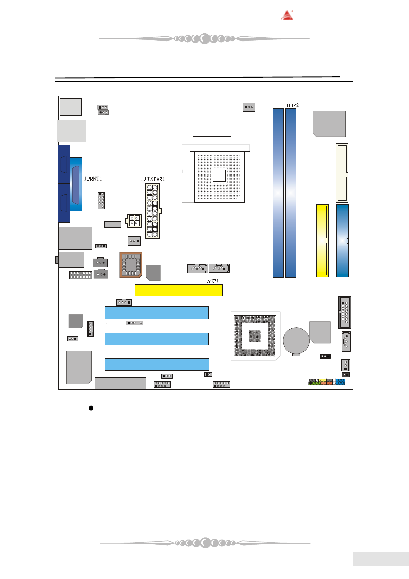
BAT1
IDE1
IDE2
FDD1
DDR1
1
15
JGAME1
JCMOS1
JSFAN1
NVIDIA NF3 250
3
4
PCI1
PCI2
PCI3
JSATA1
JSATA3
JSATA2
JCI111
J3 SATA
Bridge
JCOM3
1
Super I/O
(Optional)
(Optional)
(Optional)
(Optional)
(Optional)
(Optional)
(Optional)
(Optional)
(Optional)
(Optional)
(Optional)
(Optional)
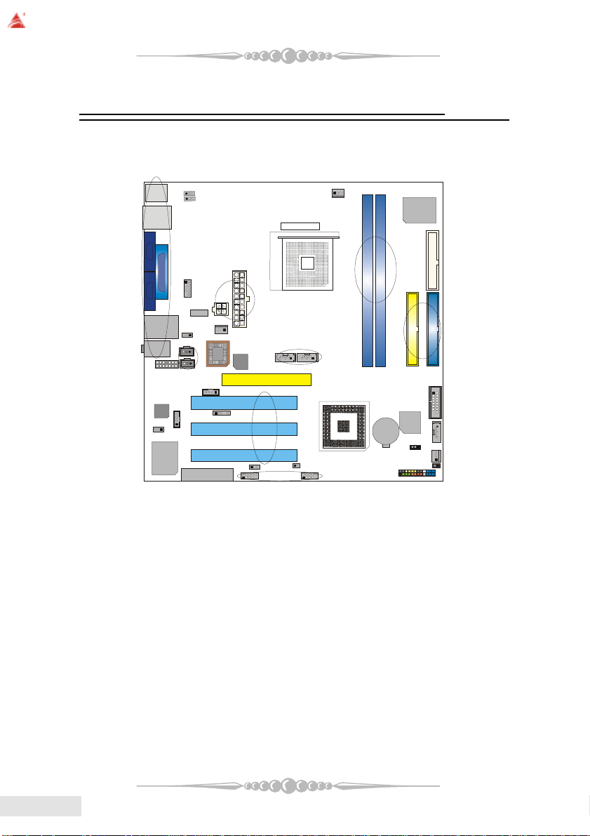
Section 1. Layout of K8NHA-M Grand
JCOM1
JCOM2
JUSBLAN1
JAUDIO
1
JAUDIO1
CODEC
J1394V1
VIA
VT 6307
JKBMS1
J1394_USB1
1
JSPDIF_OUT
1
1
1
JKBMSV1
1
JUSBV1
JATXPWR2
J1394A1
1
JUSBV2
1
1
JSPDIF_IN
JCDIN2
JCDIN1
1
CNR1
JCFAN1
1
IT 8712F
JUSB1
CPU1
2
1
1
JPANEL1
1
1
2
2
Socket 754
1
JSFAN2
BIOS
RTL8201BL
11
1
JDJ1
1
JUSBV3
1
JUSB2
1
NOTE: “ ” represents the first pin.
55
5
55
EnglishEnglish
English
EnglishEnglish
BIOSTAR Motherboard
BAT1
NVIDIA CK8S
SATA
Bridge1Super I/O
Section 2. Components Index
This section helps you to locate the components in the motherboard and to find
the details about them easily according to the mentioned pages.
B
C
A
D
F
H
G
BIOS
I
1
J
CODEC
O
N
VIA
VT 6307
A Back Panel Connectors (p. 18) B JKBMSV1: 5V/5VSB Selection for Keyboard/Mouse (p. 16)
C JUSBV1: 5V/5VSB Selection for J1394_USB1 (p. 14) D JCOM3*: COM3 Header (p. 14)
E JATXPWR1-2: A TX Power Connectors (p. 16) F J1394A1*: Front 1394A Header (p. 17)
G JSFAN2: System Fan Header (p. 12) H JUSBV2: 5V/5VSB Selection for JUSBLAN1 (p. 14)
I JSPDIF_OUT/(JSPDIF_IN)*: Digital Audio Connectors (p.17) J JAUDIO1: Front Audio Header (p. 16)
K JSATA1*-3: Serial ATA Connectors (p. 13) L AGP1: Accelerated Graphics Port Slot (p. 13)
M JCDIN2: CD-Rom Audio-In Header (p. 15) N J1394V1*: Power Source Selection for J1394A1 (p. 17)
O JCDIN1: CD-Rom Audio-In Header (p. 15) P JDJ1*: Audio DJ Connector (p. 17)
Q PCI1-3: Peripheral Component Interconnect Slots (p. 13) R CNR1*: Communication Network Riser Slot (p. 13)
S JUSBV3*: 5V/5VSB Selection for JUSB1/2 (p. 14) T JUSB1-2*: Front USB Headers (p. 14)
U J3 *: Flash Rom Read/Write Enable (p. 17) V JPANEL1: Front Panel Connector (p. 15)
W JCI1*: Case Open Connector (p. 14) X JSFAN1: System Fan Header (p. 12)
Y JCMOS1: Clear CMOS Jumper (p. 13) Z JGAME1*: Game Header (p. 15)
A 1 IDE1-2: Hard Disk Connectors (p. 13) B 1 DDR1-2: DDR DIMM Modules (p. 8)
C 1 FDD1: Floppy Disk Connector (p. 12) D1 JCFAN1: CPU Fan Connector (p. 11)
RTL8201BL
M
P
R
Socket 754
E
K
L
Q
S
U
T
CPU1
D1
B1
IT 8712F
C1
A1
Z
K
Y
X
W
V
stands for “optional”.
*
EnglishEnglish
English
EnglishEnglish
66
6
66
BIOSTAR Motherboard
Section 3. K8NHA-M Grand Features
In this section, you shall find all the information about the
motherboard in your computer, including its features, layout,
component index, various jumpers, headers, connectors, and also
the installation guide to help you a quick and correct installation
of your system.
A. Hardware
CPU
* Supports Socket 754.
* Supports the AMD Athlon 64
* Running at 200/400/600/800 MHz Front Side Bus.
Chipset
* NVIDIA® CrushK8S (nForce3 250)
- HyperTransport link to the AMD K8 CPU.
- Supports AGP3.0 8X interface.
- Running at 200/400/600/800 MHz Front Side Bus.
- Single USB 2.0 EHCI/Dual USB 1.1 OHCI, 8 ports.
- Supports S-ATA(n)
- PCI 2.3 interface supporting.
- Supports system and power management.
- AC’97 2.3 interface.
®
Socket-754 processor start from 3200+/2.0GHz.
Super I/O
* Chip: ITE IT8712F.
* Low Pin Count Interface.
* Provides the most commonly used legacy Super I/O functionality.
* Environment Control initiatives,
- H/W Monitor
- Fan Speed Controller
- ITE's “Smart Guardian” function
Slots
* Three 32-bit PCI bus master slots.
* One AGP 4X/8X slot.
* One CNR slot. (optional)
77
7
77
EnglishEnglish
English
EnglishEnglish
BIOSTAR Motherboard
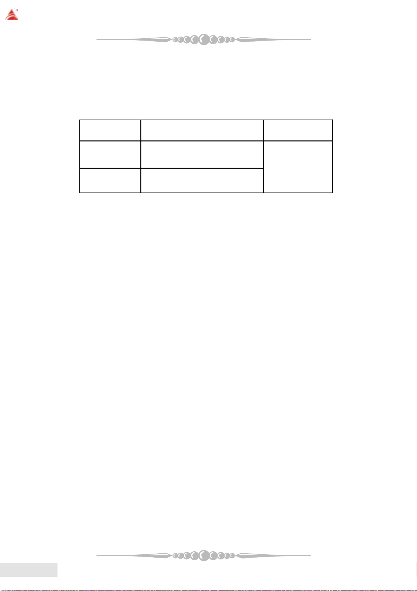
Main Memory
* Supports up to two DDR devices.
* Supports 200/266/333/400MHz (with ECC) DDR devices.
* Maximum memory size is 2GB.
T otal Memory Size with Unbuffered DIMMs
1RDD
2RDD
On Board IDE
* Supports four IDE disk drives.
* Supports PIO Mode 5, and Ultra DMA 33/66/100/133 Bus Master Mode.
* Supports Integrated Serial ATA Interface
- 2 Serial ATA (SATA) ports.
- Supports RAID 0, 1, 0+1 (SATA+PATA)
- Compliant with SATA 1.0 specification
- Data transfer rates up to 150 MB/s
tekcoSMMID
noitacoL
***only for your reference***
eludoMRDD
-1/BM215/BM652/BM821/BM46
1*BG
-1/BM215/BM652/BM821/BM46
1*BG
eziSyromeMlatoT
)BM(
BG2sixaM
EnglishEnglish
English
EnglishEnglish
1394 Chip (optional)
* Chip: VIA VT6307.
* Supports 2 ports with transfer up to 400Mb/s.
LAN PHY
* Chip: Realtek RTL8201BL.
* Supports 10/100 Mb/s operation.
* Half/Full duplex operation.
* Supports MII interface.
Serial ATA Bridge (optional)
* Chips: 88I8030 Serial ATA Bridge
* Supports both host and device operation.
* Selectable maximum speeds of 66/100/133/150 Mb/s.
* Ultra low power consumption.
* Employs the latest SATA transceiver (PHY) technology.
* Supports SSC.
* Supports 1 Serial ATA (SATA) port.
88
8
88

On Board AC’97 Sound Codec
* Chip: ALC655
* Compliant with AC’97 specification.
* AC’97 2.3 interface.
* Supports S/PDIF-In (optional), S/PDIF-Out.
* Supports 6 channels.
On Board Peripherals
a. Rear side
- 2 x serial ports. (COM1/COM2)
- 1 x Parallel Port
- Supports Audio ports in vertical.
- 1 x RJ-45 LAN jack.
- Supports PS/2 mouse and PS/2 keyboard.
- Supports 4 USB2.0 ports.
- 1 x IEEE 1394A connector (optional)
b. Front Side
- Supports 1 floppy port supports 2 FDDs with 360K, 720K, 1.2M, 1.44M
and 2.88Mbytes.
- Supports 4 USB2.0 ports.
- 1 x game port (optional)
- Supports 1 S/PDIF-Out and 1 S/PDIF-In connector (optional).
- 1 x IEEE 1394 port (optional)
BIOSTAR Motherboard
B. BIOS & Software
BIOS
* A ward legal BIOS.
* Supports APM1.2.
* Supports ACPI.
* Supports USB Function.
* The setup procedures can be found in the Setup Driver CD.
Software
* Supports WarpspeederTM, 9th TouchTM, FLASHERTM, WatchdogTM,
WinFlasher
* Offers the highest performance for Windows 98 SE, Windows 2000, Windows
Me, Windows XP, Linux, SCO UNIX, etc.
TM
99
9
99
EnglishEnglish
English
EnglishEnglish
BIOSTAR Motherboard
Section 4. P ackage contents
Check what you have bought before you start your DIY action.
If there are anything missing, please contact your dealer
immediately.
* HDD Cable X 1
* FDD Cable X 1
* User's Manual X1
* USB 2.0 Cable X1 (optional)
* Rear I/O Panel for ATX Case X1
* Fully Setup Driver CD X1
* StudioFun! Application CD X1 (optional)
* S/PDIF Cable X 1 (optional)
* Serial ATA Cable X 1 (optional)
EnglishEnglish
English
EnglishEnglish
1010
10
1010

BIOSTAR Motherboard
1
Section 5. Installation and Setup
In this section, you will learn how to install the CPU, DDR
Module, and also how to set up jumpers and all the information
about the components on the motherboard. Not only can you find
the installation steps, but also the details and locations of the
components on the motherboard.
1. CPU Installation
The motherboard supports the AMD Athlon 64® Socket-754 processor. When
you are installing the CPU, make sure the CPU has a cooling fan attached on the right
to prevent overheating. If you do not find the cooling fan, contact your dealer and make
sure to install them before turning on the computer.
Step1: Pull the lever sideways away from the socket and then raise the
lever up to a 90-degree angle.
Step2: Look for the white dot/cut edge. The white dot/cut edge should
point towards the lever pivot. The CPU will fit only in the correct orientation.
Step3: Hold the CPU down firmly, and then close the lever.
Step4: Put the CPU fan on the CPU and buckle it. Connect the CPU fan
power cable to the JCFAN1. This completes the installation.
Step 1 Step 2 Step 3 Step 4
2 Central Processing Unit: CPU
These fan headers support cooling fans built in the computer. Orient the fans to
make the heat sink fins to allow air flow to go across the onboard heat sinks instead of
the expansion slots. The fan wiring and plug may be different according to the fan
manufacturer. Connect the fan fable to the connector while matching the black wire to
the ground pin.
(1) CPU Fan Headers: JCFAN1
Pin Assignment
1 Ground
2 +12V
3 FAN RPM Sense
1111
11
1111
EnglishEnglish
English
EnglishEnglish

BIOSTAR Motherboard
1
(2) System Fan Headers: JSFAN1/JSFAN2
Pin Assignment
1 Ground
2 +12V
3 FAN RPM Sense
3. Installing DDR Module
1. Unlock a DIMM slot by
pressing the retaining clips
outward. Align a DIMM on the
slot such that the notch on the
DIMM matches the break on
the slot.
2. Insert the DIMM firmly and
vertically into the slot until the
retaining chip snap back in place
and the Dimm is properly
seated.
***Note!*** :
To assure the system safety, if you need to change DDR modules, firstly,
please unplug the 20-pin power cable with the power connector, then you can
change the modules. Afterwards, plug the cable with the power connector, and
finally you can boot up the system.
EnglishEnglish
English
EnglishEnglish
4. How to set up Jumpers?
The illustration shows how to set up jumpers. When the Jumper cap is placed
on pins, the jumper is “close”. IF no jumper cap is placed on the pins, the jumper is
”open”. The illustration shows a 3-pin jumper whose pin1and 2 are “close” when
jumper cap is placed on these 2 pins.
Jumper open Jumper close Pin1-2 close
5. Jumpers, Headers, Connectors & Slots:
(1) Floppy Disk Connector: FDD1
The motherboard provides a standard floppy disk connector that supports
360K, 720K, 1.2M, 1.44M and 2.88M floppy disk types. This connector
supports the provided floppy drive ribbon cables.
1212
12
1212
BIOSTAR Motherboard
(2) Hard Disk Connectors: IDE1/ IDE2
The motherboard has a 32-bit Enhanced PCI IDE Controller that provides PIO
Mode 0~4, Bus Master, and Ultra DMA 33/ 66/ 100/ 133 functionality. It has
two HDD connectors IDE1 (primary) and IDE2 (secondary).
The IDE connectors can connect a master and a slave drive, so you can connect
up to four hard disk drives. The first hard drive should always be connected to
IDE1.
(3) Peripheral Component Interconnect Slots: PCI1-3
This motherboard is equipped with 3 standard PCI slots. PCI stands for
Peripheral Component Interconnect, and it is a bus standard for expansion
cards. This PCI slot is designed as 32 bits.
(4) Accelerated Graphics Port Slot: AGP1
Your monitor will attach directly to that video card. This motherboard sup-
ports video cards for PCI slots, but it is also equipped with an Accelerated
Graphics Port (AGP). An AGP card will take advantage of AGP technology to
improve video efficiency and performance, especially with 3D graphics.
(5) Communication Network Riser Slot: CNR1 (optional)
The CNR specification is an open Industry Standard Architecture, and it de-
fines a hardware scalable riser card interface, which supports modem only.
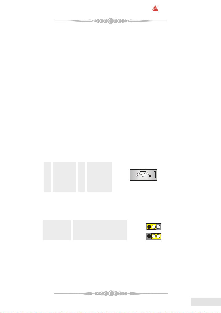
(6) Serial ATA Connector: JSATA2/JSATA3/(JSATA1: optional)
The motherboard has a PCI to SAT A Controller with 2 channels ST AT interface.
It satisfies the SATA 1.0 spec and can transfer data with 150 MB/s speed.
Pin Assignment Pin Assignment
1 Ground 2 TX+
3 TX- 4 Ground
5 RX- 6 RX+
7 Ground
1234567
(7) Clear CMOS Jumper: JCMOS1
This jumper helps you to clear the Real Time Clock (R TC) Ram in CMOS. You
can erase the CMOS RTC Ram data to clear the CMOS memory of date, time,
and system setup parameters.
JCMOS1 Assignment
Pin 1-2 Close Normal Operation (default)
Pin 2-3 Close Clear CMOS Data
* Clear CMOS Procedures:
1. Remove AC power line.
2. Set the jumper to "Pin 2-3 Close".
3. Wait for five seconds.
4. Set the jumper to "Pin 1-2 Close".
5. Power on the AC.
6. Reset your desired password or clear the CMOS data.
1
1
1313
13
1313
EnglishEnglish
English
EnglishEnglish
BIOSTAR Motherboard
2
10
1
2
1
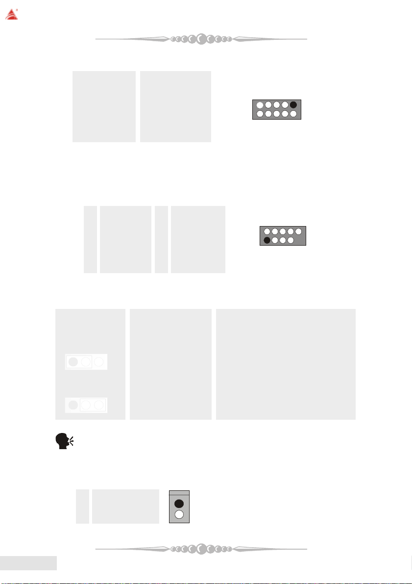
(8) COM3 Header: JCOM3 (optional)
Pin Assignment Pin Assignment
1 RIN1 2 RIN3
3 DOUT2 4 ROUT3
5 Ground 6 RIN2
7 DOUT1 8 RIN4
9 -XRI1 10 NA
(9) Front USB Header: JUSB1/ (JUSB2: optional)
The motherboard provides one/(two) USB 2.0 Pin Header. USB 2.0 technology
increases Data transfer rate up to a maximum throughput of 480 Mbps, which
is 40 times faster than USB 1.1, and is ideal for connecting high-speed USB
interface peripherals such as USB HDD, digital cameras, MP3 players, printers,
modems, etc.
Pin Assignment Pin Assignment
1 +5V(fused) 2 +5V(fused)
3 USBP-0/(-6) 4 USBP-1/(-7)
5 USBP+0/(+6) 6 USBP+1/(+7)
7 Ground 8 Ground
9 KEY 10 NC
(10) Power Source Selection for USB: JUSBV1/JUSBV2/JUSBV3 (optional)
9
EnglishEnglish
English
EnglishEnglish
JUSBV1/JUSBV2 Assignment Description
JUSBV3
Pin 1-2 close +5V JUSBV1: 5V for J1394_USB1
1 3
Pin 2-3 close +5V Standby Voltage 5V standby to power on.
1
(11) Case Open Connector: JCI1 (optional)
Pin Assignment
1 Ground
2 Case Open Signal
1414
14
1414
3
Note: In order to power-on USB devices function, "JUSBV1/JUSBV2/
JUSBV3" jumper cap should be placed on pin 2-3 respectively.
1
JUSBV2: 5V for JUSBLAN1
JUSBV3: 5V for JUSB1 port.

PWR_LED
HLED
24
23
IR
1
JCDIN1/JCDIN2
(12) CD-ROM Audio-In Header: JCDIN1/JCDIN2 (optional)
This header allows you to receive stereo audio input from sound sources, such
as CD-ROM, TV Tuner, MPEG card, etc.
Pin Assignment
1 Left Channel Input
2 Ground
3 Ground
4 Right Channel Input
(13) Game Header: JGAME1 (optional)
Pin Assignment Pin Assignment
1 +5V 2 +5V
3 Joystick B Button 1 4 Joystick A Button 1
5 Joystick B Coordinate X 6 Joystick A Coordinate X
7 MIDI Output 8 Ground
9 Joystick B Coordinate Y 10 Ground
11 Joystick B Button 2 12 Joystick A Coordinate Y
13 MIDI Input 14 Joystick A Button 2
15 NA 16 +5V
(14) Front Panel Connector: JPANEL1
The connector is for electrical connection to the front panel switches and
LEDs.
SLP
(+)
2
1
SPK
(+)
ON/OFF
(-)(+)
(-)
RST
IR
BIOSTAR Motherboard
12
Pin Assignment Function Pin Assignment Function
1 +5V Speaker 2 Sleep Control SleepButton
3 NA Connector 4 Ground
5 NA 6 NA NA
7 Speaker 8 Power LED (+) POWER LED
9 HDD LED (+) Hard DriveLED 10 Power LED (+)
11 HDD LED (-) 12 Power LED (-)
13 Ground ResetButton 14 Power Button Power-on Button
15 Reset Control 16 Ground
17 NA 18 KEY
19 NA IrDA 20 KEY IrDA
21 +5V Connector 22 Ground Connector
23 IRTX 24 IRRX
1515
15
1515
EnglishEnglish
English
EnglishEnglish
BIOSTAR Motherboard
14
13
123
4
1
0
1
(15) 5V / 5VSB Selection for KB: JKBMSV1 (optional)
JKBMSV1 Assignment Description
Pin 1-2 close +5V 5V for keyboard and mouse
Pin 2-3 close +5V_SB 5V standby for keyboard and
(16) Power Connectors: JATXPWR1/ JATXPWR2
The motherboard supports ATX power supply for the power system. Before
installing the power supply connector, please make sure that all components are
installed properly.
PIN Assignment PIN Assignment
1 +3.3V 11 +3.3V
2 +3.3V 12 -12V
3 Ground 13 Ground
4 +5V 14 PS_ON
5 Ground 15 Ground
6 +5V 16 Ground
7 Ground 17 Ground
8 PW_OK 18 -5V
9 +5V_SB 19 +5V
10 +12V 20 +5V
mouse to power on your system
10
1
1
2
1
EnglishEnglish
English
EnglishEnglish
PIN Assignment PIN Assignment
1 +12V 3 Ground
2 +12V 4 Ground
(17) Front Panel Audio Header: JAUDIO1
The connector allows you to connect to the front panel audio.
Pin Assignment Pin Assignment
1 Mic In 2 Ground
3 Mic Power 4 Audio Power
5 RT Line Out 6 RT Line Out
7 Reserved 8 Key
9 LFT Line Out 10 LFT Line Out
11 RT Line In 12 RT Line In
1616
16
1616
13 LFT Line In 14 LFT Line In
2
1
BIOSTAR Motherboard
1
1
2
10
1
1
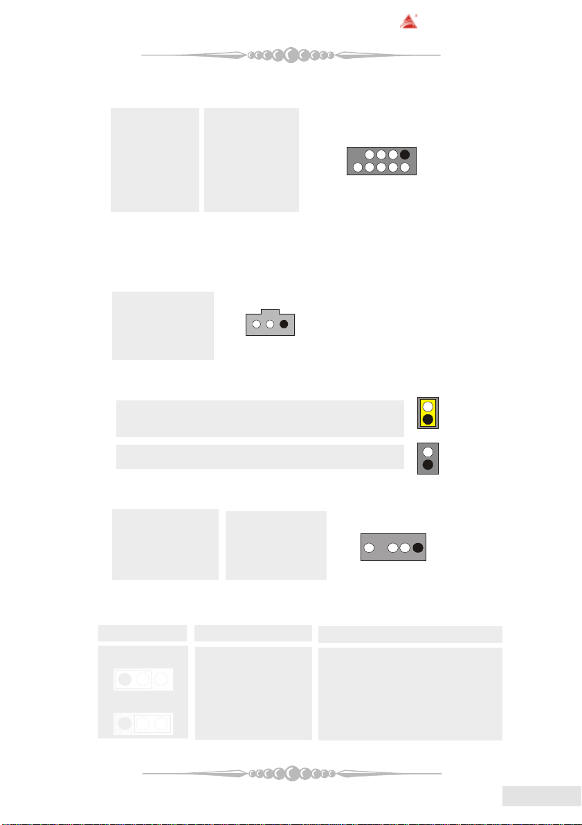
(18) Front 1394 Header: J1394A1 (optional)
Pin Assignment Pin Assignment
1 A1+ 2 A13 Ground 4 Ground
5 B1+ 6 B17 +12V 8 +12V
9 KEY 10 NA
(19) Digital Audio Connector: JSPDIF_OUT/ (JSPDIF_IN: optional)
The connector is used to connect SPDIF (Sony & Philips Digital Interconnect
Format) interface for digital audio transmission.
Pin Assignment
1 +5V
2 SPDIF_OUT
3 Ground
(20) Flash Rom Read/Write Enable : J3 (optional)
J3 Assignment
Pin1-2 on Enable the flash Rom to read and write.
9
Pin 1-2 off Disable the flash Rom to read and write.
(21) AUDIO DJ Connector: JDJ1 (optional)
Pin Assignment Pin Assignment
1 SMBDATA 2 SMBCLK
3 INT_B 4 KEY
5 ATX_PWROK
(22) Power Source Selection for IEEE1394: J1394V1 (optional)
J1394V1 Assignment Description
Pin 1-2 close +3.3V 3.3V for IEEE1394A connector
1 3
Pin 2-3 close +3.3V Standby Voltage 3.3V Standby Voltage for IEEE1394A
1 3
located at the J1394A1 header.
connector located at the J1394A1
header.
5
1717
17
1717
EnglishEnglish
English
EnglishEnglish
BIOSTAR Motherboard
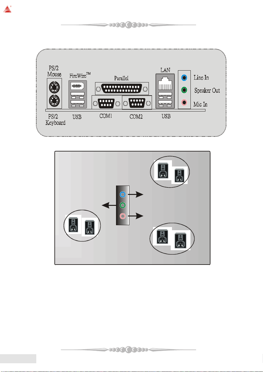
(23) Back Panel Connectors
6 Channel Spea kers
EnglishEnglish
English
EnglishEnglish
1818
18
1818
Speaker Out
Line In/ Rear Speaker
Mic In/ Cente r & Bass

BIOSTAR Motherboard
Francais
Caracteristiques de K8NHA-M Grand
Processeur
* Prend en charge le Socket 754.
* Prend en charge le processeur AMD Athlon 64?Socket-754 à partir de 3200+/
2.0GHz.
* Exécution sur Bus avant à 200/400/600/800 MHz.
Chipset
* NVIDIA CrushK8S (nForce3 250)
- Liaison HyperTransport vers le processeur AMD K8.
- Prend en charge l’interface AGP3.0 8X.
- Exécution sur Bus avant à 200/400/600/800 MHz.
- 8 ports USB 2.0 EHCI unique/USB 1.1 OHCI double.
- Prend en charge S-ATA(n)
- Prise en charge interface PCI 2.3.
- Prend en charge la gestion de l’alimentation et système.
- Interface AC’7 2.3.
IDE sur carte
* Prend en charge quatre unités de disques IDE.
* Prend en charge PIO Mode 5, Mode Bride et Mode Ultra DMA 33/66/100/
133 Bus Maître
* Prend en charge l’interface ATA série intégrée
- Prend RAID 0, 1, 0+1 (SATA+PATA)
- 2 ports série ATA (SATA).
- Compatible avec la spécification SAT A 1.0
- Transfert de données jusqu’à 150 Mo/s
Chip 1394 (optionnel)
* Chip : VIA VT6307.
* Prend en charge 2 ports avec transfert jusqu’à 400Mo/s.
LAN PHY
* Chip: Realtek RTL8201BL.
* Prend en charge les opérations 10/100 Mb/s.
1919
19
1919
EnglishEnglish
English
EnglishEnglish
 Loading...