

Page 1

K8NHA-M BIOS Setup
BIOS Setup........................................................................................1
1 Main Menu.....................................................................................................3
2 Standard CMOS Features .............................................................................. 6
3 Advanced BIOS Features...............................................................................9
4 Advanced Chipset Features..........................................................................12
5 Integrated Peripherals ..................................................................................16
6 Power Management Setup ...........................................................................21
7 PnP/PCI Configurations ...............................................................................24
8 PC Health Status ..........................................................................................26
9 Voltage Control............................................................................................28
i
Page 2

BIOS Setup
Introduction
T his manual discuss ed Award™ Setup pr ogram built into th e ROM BIOS. T he Setup
program allows users to modify the basic system configuration. This special information is
th en st ored in battery-backed RAM so th at it retain s the S etup information wh en th e power
is turned off.
T he Award B IOS™ ins talled in your comp uter system’s RO M (R ead O nly Memor y) is a
custom version of an industry standard BIOS. This means that it supports Nvidia CK8
processor input/output system. The BIOS provides critical low-level support for standard
devices such as disk drives and serial and parallel ports.
Adding important has customized the Award BIOS™, but nonstandard, features such as
virus and password protection as well as special support for detailed fine-tuning of the
chipset controlling the entire system.
The rest of this manual is intended to guide you through the process of configuring your
system using Setup.
Plug and Play Support
These AWARD BIOS supports the Plug and P lay Version 1.0A specification. ESCD
(Extended System Configuration Data) write is supported.
EPA Gree n PC Support
This AWARD BIOS supports Version 1.03 of the EPA Green PC specificat ion.
APM Support
These AWARD BIOS supports Version 1.1&1.2 of the Advanced Power Management
(APM) specification. Power management features are implemented via the System
Management Interrupt (SMI). Sleep and Suspend power management modes are supported.
This AWARD BIOS can manage power to the hard disk drives and video monitors .
ACPI Support
Award ACPI BIOS support Version 1.0 of Advanced Configurat ion and Power interface
specif ication (ACPI). It provides ASL code for power management and device
configuration capabilities as defined in the ACPI specification, developed by Microsoft,
Intel and Toshiba.
1
Page 3

PCI Bus Support
This AWARD BIOS also supports Version 2.1 of the Intel PCI (Peripheral Component
Interconnect) local bus specification.
DRAM Support
DDR DRAM (Double Data Rate Synchronous DRAM) are supported.
Suppo rted CP Us
T his AWARD BIO S support s the Nvidia
Us i ng S e t up
In general, you use the arrow keys to highlight items, press <Enter> to select, use the
<PgUp> and <PgDn> keys to change entries, press <F1> for help and press <Esc> to quit.
The following table provides more detail about how to navigate in the Setup program by
using the keyboard.
Keystroke Function
Up arro w Move to p revious item
Down arrow Move to ne xt item
Left arrow Move to the item on the left (menu bar)
Right arro w Move to the item on the right (menu bar)
Move E nter Move to the item you desire d
PgUp key Increase the numeric value or make changes
PgDn key Decrease the numeric value or make changes
+ Key Increase the numeric value or make changes
- Key Decrease the numeric value or make changes
Esc key Main Menu – Quit and not save changes into CMOS
F1 key Genera l help o n Se tup naviga tion ke ys
F5 key Load previous values from CMOS
F7 key Load the optimized defaults
F10 key Save all the CMOS changes and exit
®
CPU.
Status Page Setup Menu and Option Page Setup Me nu – Exit
Current page and return to Mai n Menu
2
Page 4
1 Main Menu
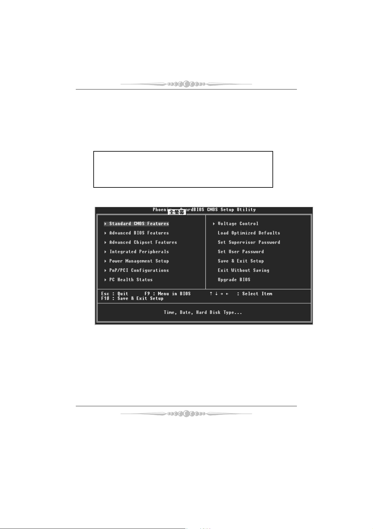
Once you enter Award BIOS™ CMOS Setup Utility, the Main Menu will appear on the
screen. The Main Menu allows you to select from several setup functions. Use the arrow
keys to select among the items and press <Enter> to accept and enter the sub-menu.
0
WARNING
The information about BIOS defaults on manual (Figure
1,2,3,4,5,6,7,8,9) is just for reference, please refer to the BIOS
installed on board, for update information.
Figure 1. Main Menu
Standard CMOS Features
This submenu contains industry standard configurable options.
Advance d BIOS Feat ures
This submenu allows you to configure enhanced features of the BIOS.
Advanced Chipset Features
This submenu allows you to configure special chipset features.
3
Page 5

Integrated Peripherals
This submenu allows you to configure certain IDE hard drive options and Programmed
Input/ Output features.
Power Management Setup
This submenu allows you to configure the power management features.
PnP/PCI Configurations
This submenu allows you to configure certain “Plug and Play” and PCI options.
PC Health Status
This submenu allows you to monitor the hardware of your system.
Voltage Control
This submenu allows you to change CPU Vcore Voltage and CPU/ PCI clock. (Ho wever,
this function is strongly recommended not to use. Not properly change the voltage
and clock may cause CPU or M/B damage!)
Lo a d O p ti mi ze d De fa u l ts
This selection allows you to reload the BIOS when the system is having problems
particu larly with the boot sequence. These configurat ions are factory settin gs optimized
for this system. A confirmation message will be displayed before defaults are set.
Set Supervisor Password
Setting the supervisor password will proh ibit everyone except the superv isor from making
changes using the CMOS Setup Utility. You will be prompted with to enter a password.
Set User Password
If the Supervisor Password is not set, then the User Password will function in the same way
as the Superv isor Passw ord. If the Sup ervisor Pa ss word is set and t he User Pa ssword is
set, the “User” will only be able to view configurations but will not be able to change them.
4
Page 6

Save & Exit Setup
Save all configurat ion changes to CMOS(memory) and exit setup. Confirmation message
will be displayed before proceeding.
Exit Without Saving
Abandon all changes made during the current session and exit setup. Confirmation message
will be displayed before proceeding.
Upgrade BIOS
This submenu allows you to upgrade bios.
5
Page 7
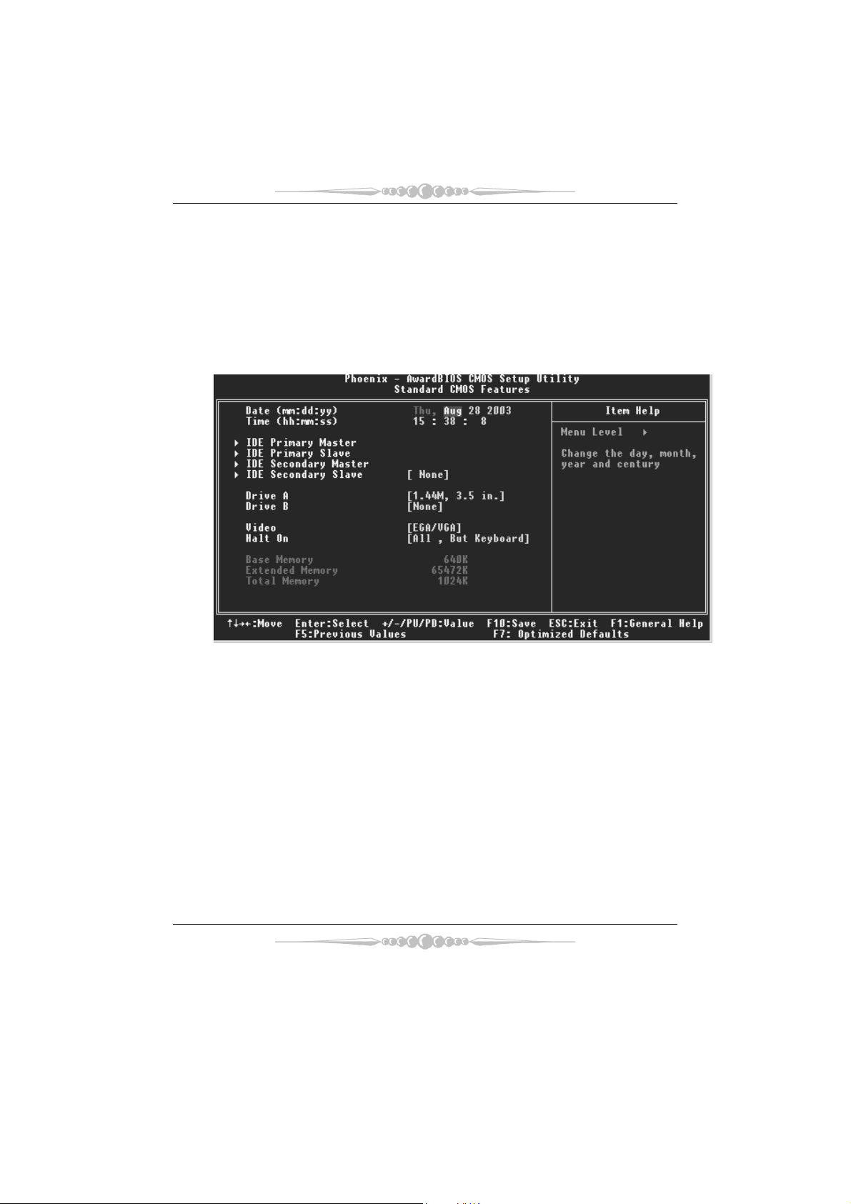
2 Standard CMOS Features
The items in Standard CMOS Setup Menu are divided into 10 categories. Each category
includes no, one or more than one setup items. Use the arrow keys to highlight the item and
then use the<PgUp> or <P gDn> keys to select the value you want in each item.
Figure 2. Standard CMOS Setup
6
Page 8

Main Menu Selections
This table shows the selections that you can make on the Main Menu.
Item Options Description
Date mm : dd : yy Set the system date. Note
Time hh : mm : ss Set the system internal
IDE Primary Master Options are in its sub
menu.
IDE Primary Slave Options are in its sub
menu.
IDE Secondary Master Options are in its sub
menu.
IDE Secondary Slave Options are in its sub
menu.
Drive A
Drive B
Video EGA/VGA
360K, 5.25 in
1.2M, 5.25 in
720K, 3.5 in
1.44M, 3.5 in
2.88M, 3.5 in
None
CGA 40
CGA 80
MONO
that the ‘Day’ automatically
changes when you set the
date.
clock.
Press <Enter> to enter the
sub menu of detailed
options
Press <Enter> to enter the
sub menu of detailed
options.
Press <Enter> to enter the
sub menu of detailed
options.
Press <Enter> to enter the
sub menu of detailed
options.
Selec t th e type of flop py
disk drive installed in your
system.
Select the default video
device.
7
Page 9

Item Options Description
Halt On All Errors
No Errors
All, but Keyboard
All, but Diskette
All, but Disk/ Key
Base Memory N/A Displays the amount of
Extended Memory N/A Displays the amount of
Total Memory N/A Displays the total memory
Select the situation in which
you want the BIOS to stop
the POST process and
notify you.
conventional memory
detected during boot up.
extended memory detected
during boot up.
available in the system.
8
Page 10

3 Advanced BIOS Features
Fig ure 3. Adva nced BIOS Setup
Virus Warning
This option allows you to choose the VIRUS Warning feature that is used to protect the
IDE Hard Disk boot sector. If this function is enabled and an attempt is made to write to the
boot sector, BIOS will display a warning message on the screen and sound an alarm beep.
Disabled (default) Virus protection is disabled.
Enabled Virus protection is activated.
Quick Power On Self Test
Enablin g this option will cause an abridged version of the Power On Self-T est (POST) to
execute after you power up the computer.
Disabled Normal POST.
Enabled (default) Enable quick POST.
Boot Up NumLock Status
Selects the NumLock. State after power on.
On (default) Numpad is number keys.
Off Numpad is arrow keys.
9
Page 11

Typematic Rate Setting
When a key is held down, the keystroke will repeat at a rate determined by the keyboard
controller. When enabled, the typematic rate and typematic delay can be configured.
The Choices: Disabled (default), Enabled.
Typematic Rate (Chars/Sec)
Sets the rate at which a keystroke is repeated when you hold the key down.
The Choices: 6 (default), 8, 10, 12, 15, 20, 24, 30.
Typematic Delay (Msec)
Sets the delay time after the key is held down before it begins to repeat the keystroke.
The Choices: 250 (default), 500,750,1000.
Security Option
This option will enab le only individuals w ith passwords to bring the system online and/or
to use the CMOS Setup Utility.
System: A password is required for the system to boot and is a lso required to access the
Setup Utility.
Setup (default): A password is required to access the Setup Utility only.
This will only apply if passwords are set from the Setup main menu.
MPS Version Co ntrol For OS
The BIOS supports version 1.1 and 1.4 of the Intel multiprocessor specificat ion.
Select version supported by the operation system running on this computer.
The Choices: 1.4 (default), 1.1.
OS Select For DRAM > 64MB
A choice other than Non-OS2 is only used for OS2 systems with memory exceeding 64MB.
The Cho ice s : No n-OS2 (default), OS2.
Small Logo (EPA) Show
T his ite m allo ws yo u to en able/ disab le dis p lay th e small E PA lo go.
The Choices: Disabled (default), Enabled.
Sum mar y Scree n Show
This item allows you to enable/disable the summary screen. Summary screen means
syst em con figur ation and P CI d evice listing.
The Choices: Enabled, Di sa ble d (default).
10
Page 12

Cache Setup
CPU Internal Cache
This item allows you to enable/disab le CPU L2 Cache ECC Checking.
The C ho ices: Enabled (default), Disabled.
External Ca che
This option you to enable or disable “Level 2” secondary cache on the CPU,
which may improve performance.
The Choices:
Enabled (default) Enable cache.
Disab led Disable cache.
Boot Seq & Floppy Setup
First/ Second/ Third/ Boot Other Device
These BIOS attempt to load the operating system from the device in the sequence
selected in these items.
The Choices: Floppy, LS120, HDD-0, SCSI, CDROM, HDD-1, HDD-2, HDD-3,
ZIP100, LAN, HPT370, Disabled, Enabled.
Swap Floppy Drive
For systems with two floppy drives, this option allows you to swap logical drive
assignments.
The Choices: Disabled (default), Enabled.
Boot Up Floppy Seek
Enablin g this option will test the floppy drives to determine if they have 40 or 80
tracks. Disabling this option reduces the time it takes to boot-up.
The Choices: Disabled (Default, Ena bled.
11
Page 13

4 Advanced Chipset Features
T his su bmen u allows yo u to c onfigu re th e spec ific fe atures of th e chipset ins talle d on y our
system. This chipset manage bus speeds and access to system memory resources, such as
DRAM. It also coordinates communications with the PCI bus. The default settings that came
with your system have been optimized and therefore should not be changed unless you are
suspic ious that the settings have been changed incorrectly.
Fig ure 4. Adva nce d Chipset Set up
DRAM Configuration
DDR Timing Setting by
DDR Timing Setting by SPD or ITEM.
The Cho ices: Au to (Default), Manual.
Max Memclock (MHz)
P laces an artifical memory clock lim it on the system. Memory is prevented
from running faster than this frequency.
T he Choices: 200 (Default), 166, 133, 100.
CAS# Latency
This field specify the cas# latency, i.e. cas# to read data valid.
The Choices: CL=2.5 (Default), CL=3.0, CL=2.0
12
Page 14

Row cycle time (tRC)
T his field specifies the ROW Cycle Time. RAS# active to RAS# active or auto
refresh of the same bank. Typically -70 Nsec.
The Choices: 9 BUS CLOCKS (Default), 7 BUS CLOCKS, 8 BUS CLOCKS,
10 BUS CLOCKS, 11 BUS CLOCKS, 12 BUS CLOCKS, 13 BUS CLOCKS, 14
BUS CLOCKS, 15 BUS CLOCKS, 16 BUS CLOCKS, 17 BUS CLOCKS, 18
BUS CLOCKS, 19 BUS CLOCKS, 20 BUS CLOCKS, 21 BUS CLOCKS,
22BUS CLO CKS.
Ro w refresh c yc time ( tRFC)
This fie ld specifies the ROW Refresh Cycle Time. Auto-refresh active to RAS#
active or RAS# to Auto-refresh. Similar to Trc. Typically 75-90 Nsec.
The Choices: 10 BUS CLOCKS (Default), 9 BUS CLOCKS, 11 BUS CLOCKS,
12 BUS CLOCKS, 13 BUS CLOCKS, 14 BUS CLOCKS, 15 BUS CLOCKS, 16
BUS CLOCKS, 17 BUS CLOCKS, 18 BUS CLOCKS, 19 BUS CLOCKS, 20
BUS CLOCKS, 21 BUS CLOCKS, 22 BUS CLOCKS, 23 BUS CLOCKS, 24
BUS CLOCKS
RAS# to CAS# Delay (tRCD)
This fie ld specifies the RAS# to CAS# Delay to read/ write command to the same
bank. Typically -20 Nsec.
The Choices: 3 BUS CLOCKS (Default), 2 BUS CLOCKS, 4 BUS CLOCKS, 5
BUS CLOCKS, 6 BUS CLOCKS, 7 BUS CLOCKS
Ro w to Row De la y (tRRD )
This field specif ies the Row# of different banks. Typically -15 Nsec.
The Choices: 2 BUS CLOCKS (Default), 3 BUS CLOCKS, 4 BUS CLOCKS.
Min RAS# active time (tRAS)
This field specif ies the minimum RAS# active time. Typically -45-60 Nsec.
The Choices: 6 BUS CLOCKS (Default), 13 BUS CLOCKS, 14 BUS CLOCKS,
15 BUS CLOCKS.
Row precharge Time (tRP)
This field specifies the Row precharge Time. Precharge to Active or
Aut o-Refre sh of the sa me ba nk. Typical ly 20-24 N sec.
The Choices: 3 BUS CLOC KS (Default), 2 BUS CLOCKS, 4 BUS CLOCKS, 5
BUS CLOCKS, 6 BUS CLOCKS.
Wri te reco v ery time ( tWR)
This bit specifies the Write recovery time. Called Trdl by Samsung, measures
when the last write datum is safely registered by the DRAM. It measures from
the last data to precharge. Samsung measures as 1.25 -1.75CK but Jedec says
15-20 ns.
The Choices: 2 BUS CLOC KS (Default), 3 BUS CLOCKS
13
Page 15

Write to Read Delay (tWTR)
T his bit spec ifies t he wr ite to read de la y. Samsung c alled th is Tc dlr ( last data in
to read command). It is measured from the rising edge following the last
non-masked data strobe to the rising edge of the next Read Command (Jedec
specs this as exactly one clock)
The Choices: 1 BUS CLOC KS (Default), 2 BUS CLOCKS
Read to Write Delay (tRWT)
T his bit spec ifies the Re ad to write delay. Th is is no t a DRAM specified timing
parameter but must be considered due to routin g latencies on the clock forwarded
bus. It is counted from first address bus slot which was not associated with part
of the read burst.
The Choices: 4 BUS CLOCKS (Default), 1 BUS CLOCKS, 2 BUS CLOCKS, 3
BUS CLOCKS, 5 BUS CLOCKS, 6 BUS CLOCKS.
Refresh period (tREF)
This field specif ies the number of clock cycles between refresh.
The Choices: 1x 2064 Cycles (Default).
CPU OverClock in MHz
T he Choices : 200 (default), 201, 202, 203, 204, 205, 206, 207.
AGP OverClock in MHz
T he Choices : 66 ( defaul t), 67, 68, 69, 70, 71, 72, 73.
AGP Aperture Size
Select the size of the Accelerated Graphics Port (AGP) aperture. The aperture is a
portion of the PCI memory address range dedicated for graphics memory address
space. Host cycles that hit the aperture range are forwarded to the AGP without
any translation.
T he Choices : 64M, 256M, 128M (Default), 32M, 16M, 8M, 4M.
AGP 3.0 Speed
T he Choices : Auto (default)
AGP 2.0 Speed
T he Choices : Auto (default), 1x, 1x2x, 1x2x4x.
AGP Fast Write
14
Page 16

When Enabled, writes to the AGP (Accelerated Graphics Port) are executed with
one wait states.
T he Choices : Auto (default), Disabled.
AGP Sideband Address
T he Choices : Auto (default), Disabled.
Speculative TLB Reloads
The Choices: Disabled (default), Enabled.
LDT Downstream Width
The Choices: Auto (def ault) , 8 bits.
LDT Speed
The Choices: 2x (default), 1x, 2.5x, 3x, 4x.
Special I/O for PCI Card
The Choices: Disabled (default), Enabled.
Base I/O Address
The Choices: 0000 (default),
I/O Length
The Choices: 1 byte (default),
System BIOS Cacheable
Select ing the “Enabled” option allows caching of the system BIOS ROM at
F0000h-FFFFFh which can improve system performance. However, any
pr ogram s writ ing t o this area of memo ry w ill caus e con flicts and result in sy stem
errors.
The Choices: Enabled, Disabled (default).
15
Page 17

5 Integrated Peripherals
Figure 5. Integrated Peripherals
IDE Func tion Setu p
If you highlight the litera l “Press Enter” next to the “IDE Function Setup” label and then press
the enter key, it will take you a submenu with the following options:
On Chi p ID E Cha nnel 0/1
The motherboard chipset contains a PCI IDE interface with support for
two IDE channels. Select “Enabled” to activate the first and/or second IDE
interface. Select “Disabled” to deactivate an interface if you are going to install a
primary and/or secondary add-in IDE interface.
The Cho ice s : En a b le d (default), Disab led.
Prima ry / Secondary /Master / Slave PIO
The IDE PIO (Programmed Input / Output) fields let you set a PIO
mode (0-4) for each of the IDE devices that the onboard IDE interface
supports. Modes 0 to 4 will increased performance progressively. In Auto mode,
the system automatically determines the best mode for each device.
The Choices: Auto (default), Mode0, Mode1, Mode2, Mode3, Mode4.
Prima ry / Secondary /Master / Slave UDMA
Ultra DMA/100 functionality can be implemented if it is supported by the IDE
hard drives in your system. As well, your operating environment requires a DMA
driver (Windows 95 OSR2 or a third party IDE bus master driver). If your hard
16
Page 18

drive and your system software both support Ultra DMA/100, select Auto to
enable BIOS support.
The Choices: Auto (default), Disabled.
IDE Prefetch Mode
The “onboard” IDE drive interfaces supports IDE prefetching for faster drive
access. If the interface does not support prefetching. If you install a primary
and/or secondary add-in IDE interface, set this option to “Disabled”.
The Cho ice s : En a b le d (default), Disab led.
IDE DMA Transfer Access
The Cho ice s : En a b le d (default), Disab led.
IDE HDD Block Mo de
Bloc k m ode is also ca lled bloc k tr ansf er, mult ip le c ommand s, or mult ip le sector
read / write. If your IDE hard drive supports block mode (most new drives do),
select Enabled for automatic detection of the optimal number of block mode
(most new drives do), select Enabled for automatic detection of the optimal
number of block read / write per sector where the drive can support.
The Choices: Enabled (default), Disabled.
Onboa rd Device
If you highlight the literal “Press Enter” next to the “Onboard Device” label and then press the
enter key, it will take you a submenu with the following options:
USB Mouse Support
Serial-ATA
OnChip US B
Th is opt ion sh ou ld be ena b le d if yo ur syst em ha s a USB ins talled on th e sys tem
board. You will need to disable this feature if you add a higher performance
controller.
The Choices: V1. 1+V2. 0 (default), Disabled, V1.1
USB Legacy Support
This item allows you to support the USB legacy.
The Choices: Enabled (Default), Disabled.
Enables support for USB attached mouse.
The Choices: Disabled (default), Enabled.
Enables support for Serial-ATA.
The Choices: Enabled (default), Disabled.
AC97 Audio
This option allows you to control the onboard AC97 audio.
The Choices: Auto (default), Disabled.
17
Page 19

MC97 Modem
This option allows you to control the onboard MC97 modem.
The Choices: Auto (default), Disabled.
MAC LAN (nVIDIA)
This option allows you to change the state of the onboard MAC LAN.
The Choices: Auto (Default), Disabled.
Onboard LAN Boot ROM
Th is ite m allows y ou to enable o r disable Onbo ard LAN Boot ROM .
The Choices: Disabled (default), Enabled.
Onboard RAID ROM
This item allows you to enable or disable Onboard RAID ROM.
The Choices: Disabled (default), Enabled.
Onboard SATA ROM
This item allows you to enable or disable Onboard SATA ROM.
The Choices: Disabled (default), Enabled.
Reltek Giga LAN Boot ROM
This item allows you to enable or disable Re ltek Giga LAN Boot ROM.
The Choices: Disabled (default), Enabled.
Reltek Me ga LAN Boot RO M
This item allows you to enable or disable Re ltek Mega LAN Boot ROM.
The Choices: Disabled (default), Enabled.
Wi reless LA N Boo t ROM
This item allows you to enable or disable Wireless LAN Boot ROM.
The Choices: Disabled (default), Enabled.
Supe r IO Device
Press Enter to configure the Super I/O Device.
O n boa rd FD C Co n tro lle r
Select Enabled if your system has a floppy disk controller (FDC) installed on the
system board and you wish to use it. If install and FDC or the system has no
floppy drive, select Disabled in this field.
The Choices: Enabled (default), Disabled.
Onboard Serial Port 1
Select an address and corresponding interrupt for the first and second serial ports.
The Choices: 3F8/IRQ4 (default), Disabled, Auto, 2F8/IRQ3,
3E8/IRQ4, 2E8/IRQ3.
Onboard Serial Port 2
18
Page 20

Select an address and corresponding interrupt for the first and second serial ports
The Choices: 2F8/IRQ 3 (default), Disabled, Auto, 3F8/IRQ4 ,
3E8/IRQ4, 2E8/IRQ3.
UART Mode Select
This item allows you to determine which Infrared (IR) function of onboard I/O
chip.
The Choices: Normal(default), ASKIR, Ir DA, SCR .
UR2 Duplex Mode
Select the value requ ired by the IR device connected to the IR port. Full-duplex
mode permits s imultaneous two-direction transmiss ion. Half-duplex mode
permits transmiss ion in one direct ion only at a time.
The Choices: Half (d efau lt), Full.
Onboard Parallel Port
This item allows you to determine access onboard parallel port controller with
which I/O Address.
The Choices: 378/IRQ7 (default), 278/IRQ5, 3BC/IRQ7, Disabled.
Parallel Port Mode
T he default va lue is SP P.
The Choices:
SPP (Default) Using Parallel Port as Standard Printer Port.
EPP Using Parallel Port as Enhanced Parallel Port.
ECP Using Parallel Port as Extended Capabilities Port.
ECP+EPP Using Parallel Port as ECP & EPP mode.
ECP M ode Use DM A
Se lect ECP po rt ty pe 1 or 3.
The Choices: 3 (default), 1.
Game Port Address
Game P ort I/O Ad dress.
The Choices: 201 (default), 209, Disabled.
Midi Port Address
Midi Port Base I/O Address.
The Choices: 330 (default), 300, Disabled.
Midi Port IRQ
T his de term ines t he IR Q in which the Mid i Por t can use.
The Choices: 10 (default), 5.
Init Display First
With systems that have multiple video cards, this option determines whether the primary
19
Page 21

disp lay uses a PCI Slot or an AGP Slot.
The Choices: PCI Slot (default), AGP.
Power on Function
This option allows you to choose the different function to power on the computer.
The Choices: Hot Key (default), Password, Mouse Move, Mouse Click, Any
K8 Power ON Password
Press Enter to configure the K8 Power ON Password.
Hot Key Powe r o n
This option allows you to choose a hot key to power on.
PWRON After PWR-Fail
This field determ ines the action the system will automatically take when power is restored
to a system that had lost power previously without any subsequent manual intervention.
There are 3 sources that provide current to the CMOS area that retains these P ower-On
instruct ions; the motherboard battery (3 V), the P ower Supply (5VSB), and the Power
Supply (3.3V). While AC is not supplying power, the motherboard uses the motherboard
battery (3V). If AC power is supplied and the Power Supply is not turned on, 5VSB from
the Power Supply is used. When the Power Supply is eventually turned on 3.3V from the
Power Supply will be used.
There are 3 options: “Former-Sts”, “On”, “Off”.
“Off” (default) Means always set CMOS to the “Off” status when AC power is lost.
“On” Means always set CMOS to the “On” status when AC power is lost
“Former-Sts” Means to maintain the last status of the CMOS when AC power is lost.
For example: If set to “Former-Sts” and AC power is lost when system is live, then after
AC power is restored, the system will automatica lly power on. If AC power is lost when
system is not live, system will remain powered off.
Key, Button Only, Keyboard 98.
The Choices: PCI Slot (default), AGP.
The Choices: Ctrl-F1 (default), Ctrl-F2, Ctrl-F3, Ctrl-F4, Ctrl-F5, Ctrl-F6,
Ctrl-F7, Ctrl-F8.
20
Page 22

6 Power Management Setup
The Power Management Setup Menu allows you to conf igure your system to utilize energy
conservation and power up/power down features.
Figure 6. Power Management Setup
ACPI Function
This item displays the status of the Advanced Configurat ion and Power Management
(ACPI).
The Choices: En ab le d (default), Disabled.
ACP I Sus pend Type
The item allows you to select the suspend type under the ACPI operating system.
The Choices: S1 (POS) (default) Power on Suspend
Power Management
This category allows you to select the type (or degree) of power saving and is directly
related to the following modes:
1.HDD Power Down.
2.Doze Mode.
3. Susp end M ode.
There are four options of Power Management, three of which have fixed mode settings
S3 (STR) Suspend to RAM
S1 + S3 POS+STR
21
Page 23

Min. Saving
Minimum power management.
Doze Mode = 1 hr.
Standby Mode = 1 hr
Su spend Mo de = 1 hr.
HDD Power Down = 15 min
Max Saving
Maximum power management only available for sl CPU’s.
Doze Mode = 1 min
Standby Mode = 1 min.
Su spend Mo de = 1 min.
HDD P ower Down = 1 min.
User Defined (default)
Allows you to set each mode individually.
When not disabled, each of the ranges are from 1 min. to 1 hr. except for
HDD Power Down which ranges from 1 min. to 15 min. and disable.
Video Off Method
T his op tion d eter mines the m anne r in which the mo nitor is goe s blan k.
V/H SYNC+Blank
This selection will cause the system to turn off the vertical and horizontal
synchronization ports and write blanks to the video buffer.
Blank Screen
This option only writes blanks to the video buffer.
DPMS (default)
Init ial display power management signaling.
HDD Power Down
When enabled, the hard disk drive will power down and after a set time of system inactivity.
Al l othe r dev ices r emain act ive.
The Choices: Disabled (de fault ), 1M in, 2Min, 3M in, 4Min, 5M in, 6Min, 7M in, 8M in,
9Min, 10Min, 11Min, 12Min, 13Min, 14Min, 15Min.
Soft-Off by PBTN
Pressing the power button for more than 4 seconds forces the system to enter the
Soft-Off state when the system has “hung.”
The Choices: Delay 4 Sec, Instant-Off (default).
22
Page 24

WOL (PME#) Fro m Soft-Off
The Choices: Disabled (default), Enabled.
WOR (RI#) From Soft-Off
The Choices: Disabled (default), Enabled.
USB Resume from S3
The Choices: Disabled (default), Enabled.
Power-On by Alarm
When you select Enabled, an alarm returns the system to Full ON state.
The Choices: Disabled (default), Enabled.
23
Page 25

7 PnP/PCI Configurations
This section describes configuring the P CI bus system. PCI, or Personal Computer
Interconnect, is a system which allows I/O devices to operate at speeds nearing the speed of
the CPU itself uses when communicating with its own special components. This section
covers some very technical items and it is strongly recommended that only experienced
users should make any changes to the default settings.
Figure 7. PnP/PCI Configurations
Reset Configuration Da ta
The system BIOS supports the PnP feature which requires the system to record which
resources are assigned and protects resources from conflict. Every peripheral device has a
node, which is called ESCD. T his node records which resources are assigned to it. The
syst em needs to recor d and upd ate ESCD to the memory lo cations. T h ese locations ( 4K)
are reserved in the system BIOS. If the Disabled (default) option is chosen, the system‘s
ESCD will update only when the new configuration var ies from the last one. If the Enabled
option is chosen, the system is forced to update ESCDs and then is automatically set to the
“D isab led” m od e.
The above settings will be shown on the screen only if “Manual” is chosen for the resources
controlled by function.
Le gacy is the term, which signif ies th at a resour ce is as signed to the ISA Bus and pro vides
non-PnP ISA add-on cards. PCI / ISA PnP signifies that a resource is assigned to the P CI
Bus or provides for ISA PnP add-on cards and peripherals.
The Choices: Disabled (default), Enabled.
24
Page 26

Resources Controlled B y
By Choosing “Auto(ESCD)” (default), the system BIOS will detect the system resources
and automatically assign the relative IRQ and DMA channel for each peripheral.By
Choosin g “Manual”, the user will need to assign IRQ & DMA for add-on cards. Be sure
that there are no IRQ/DMA and I/O port conflicts.
IRQ Resources
This submenu will allow you to assign each system interrupt a type, depending on the type
of device using the interrupt. When you press the “Press Enter” tag, you will be directed to
a submenu that will allow you to configure the system interrupts. This is only
configurable when “Resources Controlled By” is set to “Manual”.
IRQ-3 assigned to PCI Device
IRQ-4 assigned to PCI Device
IRQ-5 assigned to PCI Device
IRQ-7 assigned to PCI Device
IRQ-9 assigned to PCI Device
IRQ-10 assigned to PCI Device
IRQ-11 assigned to PCI Device
IRQ-12 assigned to PCI Device
IRQ-14 assigned to PCI Device
IRQ-15 assigned to PCI Device
PCI / VG A Pa le tte Snoop
Choose Disabled or Enabled. Some graphic controllers which are not VGA compatible
take the output from a VGA controller and map it to their display as a way to provide boot
information and VGA compatibility.
However, the color information coming from the VGA contro ller is drawn f rom the palette
table ins ide the VGA controller to generate the proper colors, and the graphic controller
needs to know what is in the palette of the VGA controller. T o do this, the non-VGA
graphic controller watches for the Write access to the VGA palette and registers the snoop
data. In PCI based systems, where the VGA controller is on the P CI bus and a non-VGA
graphic controller is on an ISA bus, the Write Access to the palette will not show up on the
ISA bus if the PCI VGA controller responds to the Write.
In this c ase, the PCI VGA controller should not res po nd t o the Write, it should only snoop
the data and permit the access to be forwarded to the ISA bus. The non-VGA ISA graphic
controller can then snoop the data on the ISA bus. Unless you have the above situation,
you should disab le this option.
Disabled(default) Disables the function.
Enabled Enables the function.
25
Page 27

8 PC Health Status
Figure 8. PC Health Status
Shutdown Temperature
This item allows you to set up the CPU shutdown Temperature. T his item only effective under
Windows 98 ACPI mode.
The Choices: Disabled (default) , 60℃/ 140℉ , 65℃/ 149℉, 70℃/ 158℉.
CPU FAN Control by
The Choice “smart” can make your CPU FAN to reduce noise.
The Choices: SMART (default), Always On.
SYS FAN Co ntrol by
The Choice “smart” can make your System FAN to reduce noise.
The Choices: SMART (default), Always On.
CPU Vcore/ 3.3V/ +5.0V/ +12V/-12V/-5V/5V (SB)/Voltage Battery
Detect the system’s voltage and battery status automatically.
26
Page 28

Current CPU Temperature
Show you the current CPU temperature.
Current CPU FAN Speed
This field displays the current CPU FAN speed.
Current SYS FAN Speed
This field displays the current speed of the SYSTEM fan.
Show H/W Monitor in POST
If you computer contain a monitoring system, it will show PC health status during POST
stage. The item offers several delay time to select you want.
The Choices: Enabled (default), Disabled .
27
Page 29

9 Frequency Control
Fig ure 9. F reque nc y Co ntrol
CPU Voltage
T his ite m allo ws yo u to se lect C P U Voltage Con trol.
The Choices: Default (default), +1.7%, +3.4%, +5.1%.
DDR Voltage
This item allows you to select DDR Voltage Control.
The Choices: Default (Default), 2.75V, 2.85V, 2.90V.
If unfortunately, the system’s frequency that you are selected is
not functioning, there are two methods of booting-up the system.
Method 1: Clear the CMOS data by setting the JCMOS1 ((2-3) closed)) as
“ON” status. All the CMOS data will be loaded as defaults setting.
Method 2: Press the <Insert> key and Power button simultaneously, after that
keep-on pressing the <Insert> key until the power-on screen showed. This
action will boot-up the system according to FSB of the processor.
28
 Loading...