


PIV-Station Installation Guide
PIV-Station
TM
Version 10.0

INTRODUCTION TO THIS MANUAL
Table of Contents
1 Introduction to This Manual..................................................................................................................................3
2 Earth Ground........................................................................................................................................................4
3 About the PIV-Station Reader..............................................................................................................................5
4 Steps in a Comprehensive Installation.................................................................................................................6
5 Planning the Installation.......................................................................................................................................7
6 Unpack All Items ..................................................................................................................................................8
6.1 Basic Components included...................................................................................... ......... ....... .......... 8
6.2 Basic Components required but not included......................................................................... .............8
7 Component Installation.........................................................................................................................................9
7.1 Basic Component Installation.................................................................................... ......... ...... ........... 9
7.2 Choosing a Network Type ............................................ .... .... .... .... ..... .... .... .... .... .... .... ......... .... .............9
7.3 Basics of RS-485 networks................................................................................................................10
7.4 RS-485 Cable Specification...............................................................................................................10
7.5 RS-485 Cable Lengths ......................................................................................................................11
7.6 RS-485 Network Topology.................................................................................................................11
7.7 Extending the RS-485 Specification..................................................................................................11
7.8 Ethernet Networks.............. .... ..... .... .... .... .... ......... .... .... .... .... .... .... ..... .... .... .... .... .... .... ........................11
8 Install Software...................................................................................................................................................12
8.1 System Requirements ...................................... .................................................................................12
8.2 Install Software .................... .... .... .... .... .... .... .... ......... .... .... .... .... .... .... ..... .... .... .... .... .... ........................12
8.3 Re-installing or Updating Software..................................................................................... .... ...........12
8.4 Post-Install Software Configuration ...................................................................................................13
8.5 USB Driver Install ..............................................................................................................................14
9 Configure Ports ..................................................................................................................................................15
10 Connect Reader for Configuration ...................................................................................................................17
10.1 Initial Reader Setup...........................................................................................................................17
10.2 Check USB COM port........................................................................................................................18
11 Mounting.................................................................................. .... .... .... .... .... .... ..... .... ........................................20
11.1 Mounting Readers .................................................... .... .... .... .... .... ..... .... .... .... .... ........ .... ..... ...............20
11.2 Mounting Templates................ .... .... .... .... .... .... ..... .... ........ .... .... .... .... ..... .... .... .... .... .... ..... ...................20
11.3 Attaching Reader to Mount................................................................................................................20
12 Power Distribution & Reader Hookup .............................................................................................................. 23
12.1 V-Station Power.................................................................................................................................23
12.2 Selecting the Right Power Supply ................................ .... .... .... ......... .... .... .... .... .... .... .... ..... .... .... .......23
12.3 Wiegand Connections................................................................... ......... .... .... .... .... .... ..... .... ...............27
12.4 ESD Shield Earth Ground Requirement............................................................................................27
12.5 RS-485...................................................................................... .........................................................27
12.6 Network Operation Issues: ................................................................................................................27
13 System Turn-Up Procedures........................................................................... ..... .... .... .... .... ............................28
13.1 System Turn up Overview .................................................................................................................28
13.2 Reader Configuration Check .................................... .... .... .... .... .... ..... .... .... ........ .... .... .... ..... .... ...........28
13.3 Ground Fault Converter Check..........................................................................................................28
13.4 Ground Fault Reader Check..............................................................................................................28
14 User Interface................................ ..... .... .... .... ........ .... .... ..... .... .... .... .... .... .... .... ..... .... ........................................29
15 Appendix A: Notices................................................................... .... .... .... ..... .... .... .... .... ....................................34
15.1 FCC Information to Users................................................................. ..... ........ .... .... .... .... ..... ...............34
15.2 FCC Class B Unintentional Radiators ........................................................... .... .... .... .... ..... .... .... .......34
15.3 CE Information to Users ....................................................................................................................34
15.4 V-Station, A, P, R: Information for Users* ..........................................Error! Bookmark not defined.
15.5 V-Station,A,G,R: Information for Users ............................................................................................35
16 Appendix B: E. U. Certification Documentation ..............................................................................................36
16.1 Restrictions of Use............................................................ .... .... .... ..... ........ .... .... .... .... .... ....................36
16.1.1 V-Station, A, P, R and PIV-Station, A, G, R.............................................................................36
Part # 430-00186-00 ©Copyright 2007, Bioscrypt Inc.
PIV-Station Installation Guide All rights reserved.
1

INTRODUCTION TO THIS MANUAL
17 Appendix C: Product Documents....................................................................................................................43
18 References...................................................................... .... .... .... ........ .... .... ..... .... .... ........................................49
19 Bioscrypt Contact Information..........................................................................................................................50
20 Bioscrypt Contact Information..........................................................................................................................51
Table of Figures
Figure 1: Earth Ground Connections ......................................................................................................................4
Figure 2: PIV-Station (shown with Optional Contact CHUID reader)......................................................................5
Figure 3: Complete System Overview....................................................................................................................9
Figure 4: Network Topologies - Star and Cascade (Daisy Chain)....................................................................... 11
Figure 5: VeriAdmin desktop icon........................................................................................................................13
Figure 6: VeriAdmin Welcome Message (Update)................................................................................ ...............13
Figure 7: VeriAdmin Welcome Message (New Install).........................................................................................13
Figure 8: Network Setup dialog............................................................................................................................16
Figure 9: Network Configuration dialog................................................................................................................18
Figure 10: Mounting Height................................................................................................................... ...............20
Figure 11: Mounting Procedures..........................................................................................................................21
Figure 12: PIV-Station Mounting Template..........................................................................................................22
Figure 13: PIV-Station Reader Pin Out (Reader Back View)...............................................................................25
Figure 14: Wiring Diagram for RS-232 to RS-485 Converter...............................................................................27
Figure 15: Amber LED..........................................................................................................................................29
Figure 16: Fingertip on Ridge-Lock......................................................................................................................29
Figure 17: Slide Finger Across Ridge-Lock..........................................................................................................29
Figure 18: Position Finger on Sensor...................................................................................................................30
Figure 19: Apply Correct Pressure.......................................................................................................................30
Figure 20: Wait for Green LED.............................................................................................................................30
Figure 21: Lift Finger Up and Off Sensor.............................................................................................................30
Figure 22: Cover Entire Sensor................................................................... .........................................................31
Figure 23: Incorrect Placement............................................................................................................................31
Figure 24: Place Finger Close to Center..............................................................................................................31
Figure 25: Do Not Rotate Finger..........................................................................................................................32
Figure 26: Finger Core.........................................................................................................................................33
Table of Tables
Table 1: RS-485 / RS-232 Communications Comparison ...................................................................................10
Table 2: Cat 5 Cable Characteristics ...................................................................................................................10
Table 3: Factory Settings .....................................................................................................................................15
Table 4: PIV-Station Power Requirements ..........................................................................................................23
Table 5: PIV-Station Weidmuller Connections.....................................................................................................24
Table 6: PIV-Station Ethernet, RJ-45, and RJ-11 Connections............................................................................26
Part # 430-00186-00 ©Copyright 2007, Bioscrypt Inc.
PIV-Station Installation Guide All rights reserved.
2

INTRODUCTION TO THIS MANUAL
1 Introduction to This Manual
This manual provides a simple step-by-step procedure for installing a PIV-Station Contact or Contactless
CHUID Reader. It covers the entire process of connecting the reader, defining the network, and enrolling users.
This manual should be used in conjunction with the Bioscrypt provided PIV-Statio n Quick Start Guide and the
PIV-Station Operator’s Manual.
The following symbols may be found throughout this manual to denote special issues the user may encounter.
Their definitions are given below.
DANGER: This symbol denotes warning to a condition that may cause death
or excessive damage to property. Please be sure to carefully read the
corresponding section in this manual.
WARNING: This symbol denotes warning to a condition that may cause
severe injury or major damage to property. Please be sure to carefully read the
corresponding section in this manual.
CAUTION: This symbol denotes caution to a condition that may cause injury or
minor damage to property. Please be sure to carefully read the corresponding
section in this manual
NOTICE: This symbol denotes notice of a situation needing additional advice
to avoid incorrect usage. Please be sure to carefully read the corresponding
section in this manual.
Part # 430-00186-00 ©Copyright 2007, Bioscrypt Inc.
PIV-Station Installation Guide All rights reserved.
3
EARTH GROUND
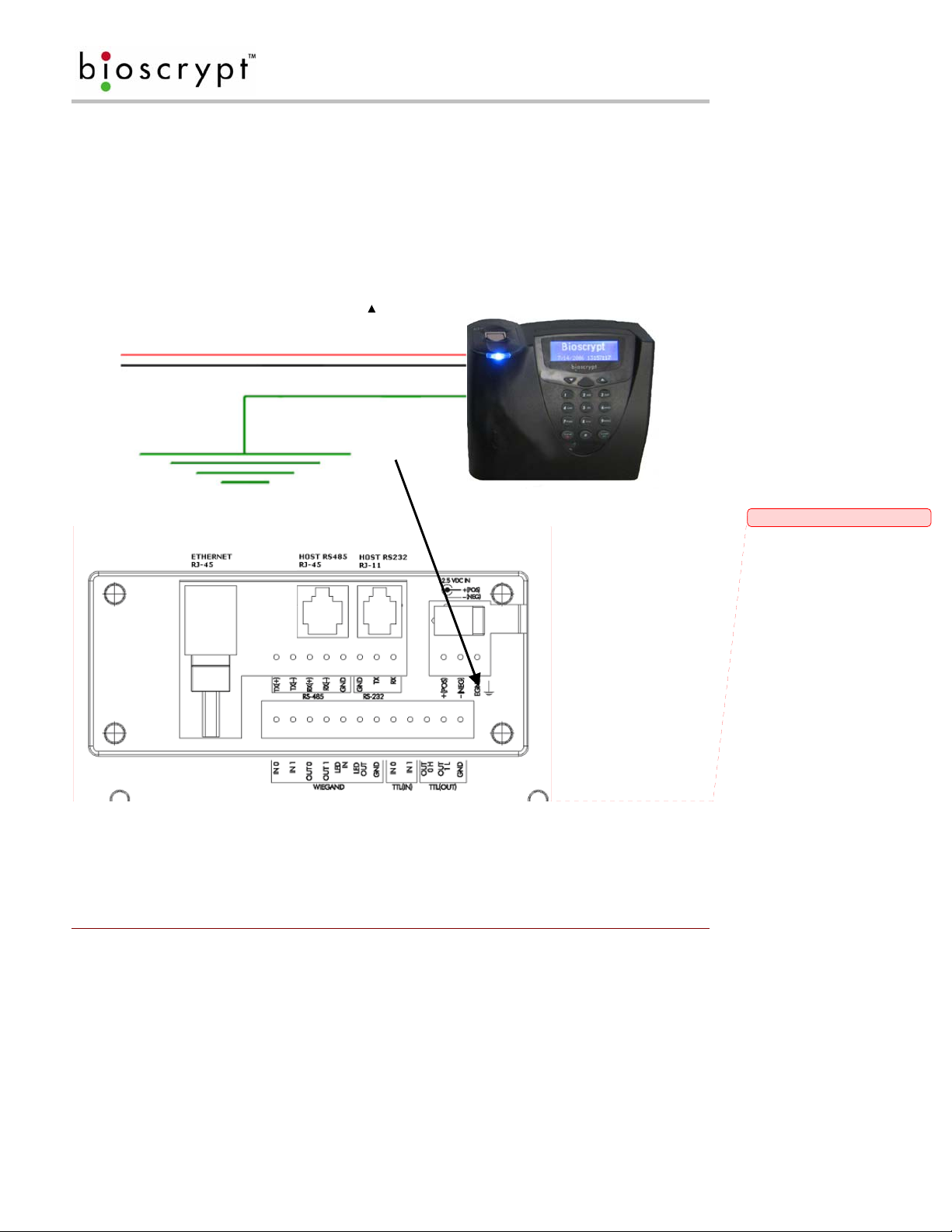
2 Earth Ground
It is extremely critical for proper operation of the Reader that the earth ground be properly connected to avoid
damage by ESD. Connect the terminal labeled EGND to earth ground. This wire should not be connected to
the neutral, the cable shield, or any other wire except earth ground. See Figure 1 (PIV-Station Contactless
CHUID Reader shown) below.
• EARTH GROUND: A low impedance path to earth for the purpose of discharging lightning,
static, and radiated energy, and to maintain the main service entrance at earth potential. Consult local
codes for guidelines.
• ESD: Electrostatic Discharge (static electricity). The effects of a static discharge can degrade
Power (+)
Power Ground (-)
or destroy semiconductor junctions for an electronic device.
Earth Ground
To protect reader from ESD
EGND connector on unit back
Figure 1: Earth Ground Connections
Part # 430-00186-00 ©Copyright 2007, Bioscrypt Inc.
PIV-Station Installation Guide All rights reserved.
4
Comment [D1]: Need new picture?
ABOUT THE PIV-STATION READER
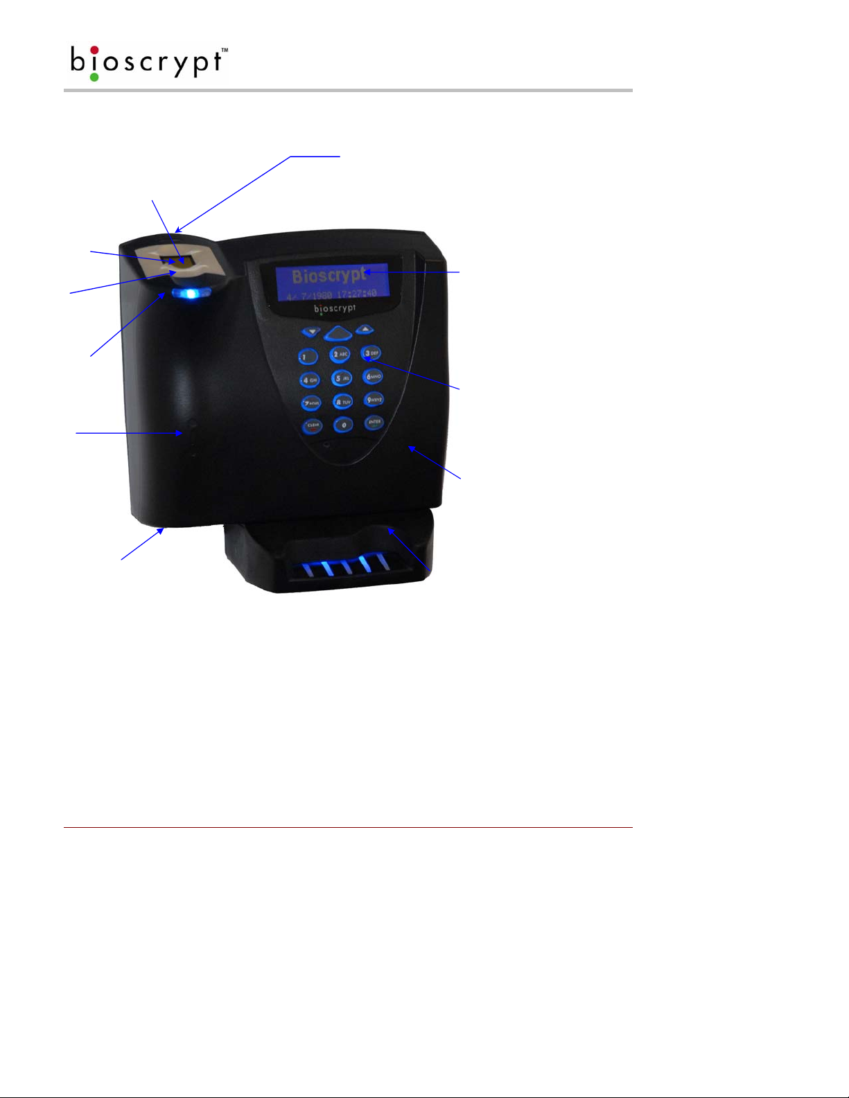
3 About the PIV-Station Reader
Conductive finger mask
Finger-scan
Sensor
Ridge-Lock™
Power
Indicator
Optional
contactless
CHUID reader
Pass/Fail Indicator
Amber
Off
Green
Red
LCD Backlit
Display
Illuminated
Keypad
ABS Plastic Body
Aux. Port
Optional Contact
CHUID reader
Figure 2: PIV-Station (shown with Optional Contact CHUID reader)
• The PIV-Station with the optional contactless CHUID reader provides a one factor authentication based on
the card’s CHUID and does not perform biometric verification.
• The PIV-Station with the optional contact CHUID reader provides a three factor authentication based on the
card’s CHUID, the template stored on the card, and the user’s finger-scan.
• The two optional readers are mutually exclusive and the contactless reader will not function when the
contact reader is installed.
• The contactless CHUID reader may be upgraded to the contact reader.
• The PIV-Station with the optional contact CHUID reader is available for 1:1 Verification only and the
template is stored on the card at the time of issuance and accessible only via the contact reader.
Part # 430-00186-00 ©Copyright 2007, Bioscrypt Inc.
PIV-Station Installation Guide All rights reserved.
5

STEPS IN A COMPREHENSIVE INSTALLATION
4 Step s in a Comprehensive Installation
Every installation is unique. Sometimes the issues are well defined and can be hand led in a standard fashion;
sometimes the issues are very specific and may not be immediately recognizable. This document addresses
the issues that may be faced with during a standard installation. The steps for a successful installation are:
• Planning the Installation – Choose the type of hardware required, decide if a network is required, and
the location and number of Readers required.
• Unpack All Items – Unpack all items and cross check against packing list.
• Install Components – Install the cabling and components needed to run system
• Install Software – Install the software needed to set up the Readers.
• Configure ports on the PC – Configure the PC ports to support reader.
• Connect reader for configuration – Connect Reader to USB cable and supply power to unit.
• Mount Readers – Mount the Readers in their final locations.
• Power distribution and reader hook up – Reader wiring via the back panel.
• Power-up Procedure – Check proper power connections and start system safely.
• User interface –Users can begin to use system.
This manual will provide more information on each of these steps in order.
WARNING. PIV-Station readers must be installed by a qualified
technician. If at anytime you do not feel qualified to perform a task,
call Bioscrypt technical support or contact a qualified installer.
Part # 430-00186-00 ©Copyright 2007, Bioscrypt Inc.
PIV-Station Installation Guide All rights reserved.
6

PLANNING THE INSTALLATION
5 Planning the Installation
Planning the installation is probably the single most important aspect to a successful installation. By the time
you are installing the system all of these details should already be known. If not, take a moment to go through
them now before beginning installation of any Readers. Planning for installation mus t take in to consideration:
the access controller, the door locks, the readers, and the need for a network.
During the planning phase, you should determine:
• What type of authentification is required for your application?
• How many doors need to be protected? The PIV-Station readers control access to a controll ed area;
areas that do not require access control don’t need readers.
• What type of reader will be on each door? Doors already inside a secure area may not need the same
type or level of security.
• If multiple PIV-Station readers require networking for template distribution/management, then a
dedicated PC is recommended to administer the system as well as an RS-485 – RS-232 converter and
cabling for serial communications or cabling for Ethernet.
• Verify that the access controller supports any of the Wiegand formats supported by the PIV-Station
readers.
• When planning the system, identify all wiring by the signal levels they are to carry. Use separate
cable/conduit for different signal groups to avoid cross talk. Plan to separate them by the following
groups:
1. Power distribution: Wires carry power to readers, door strikes, etc.
2. Data communication: RS-485, RS-232, USB, Wiegand, Ethernet, etc.
3. Signal: Door contact, request to exit push button, alarm input, etc.
• Determine any distance limitation of each type of signal when planning reader placement and use
repeaters as needed.
• Consider the environment where the equipment will operate, it may be necessary to protect the
installation with a Bioscrypt approved weather shield.
• Available quality earth ground.
If you have any unresolved issues with the items on this list contact B ioscrypt Technical Support for additional
information before beginning any installation.
Part # 430-00186-00 ©Copyright 2007, Bioscrypt Inc.
PIV-Station Installation Guide All rights reserved.
7

UNPACK ALL ITEMS
6 Unpack All Items
6.1 Basic Components included
V-Station reader
Wall mounting plate / Mullion mounting plate
Tools:
1/8” security hex key
Hardware:
(4) #6-32 screws
(4) #6 self-tapping screws
(4) #4-8 wall anchors
(14) crimps
(1) plastic Aux port door
(2) #4-40 screws
(1) Coupler
(2) Security Screws
(2) Washers
Documentation:
PIV-Station Quickstart Guide
User documentatio n (included on CD)
Documentation provided with your new reader is installed onto your computer when you install the VeriAdmin
software (also available online at http://www.bioscrypt.com
Explorer (available from the Start Menu under Programs) to navigate to C:\Program
Files\Bioscrypt\VeriAdmin\Docs or another location that you defined during the installation procedure. The
documentation is provided in Adobe® Acrobat® format (PDF). The Adobe Acrobat reader is availabl e o n the CD
or on-line at www.adobe.com
.
). To view the documentation you can use Windows
6.2 Basic Components required but not included
PC* with Windows XP and at least:
One available COM port (or Ethernet card)
USB Port
16 MB RAM
30 MB disk space
Power supply
Door controller
Networking cable
RS-232/RS-485 Converter with P/S*
Part # 430-00186-00 ©Copyright 2007, Bioscrypt Inc.
PIV-Station Installation Guide All rights reserved.
8
COMPONENT INSTALLATION
7 Component Installation
7.1 Basic Component Installation
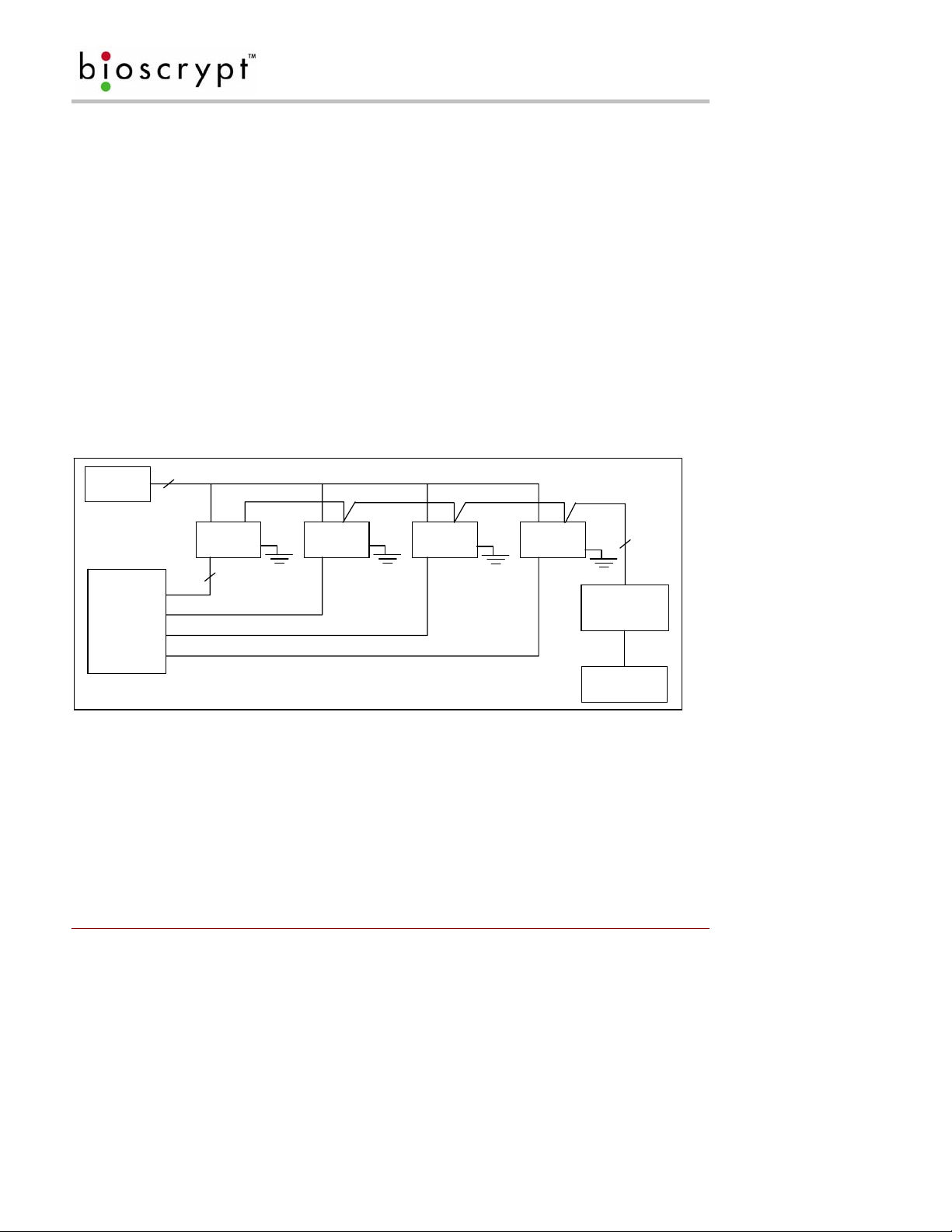
The PIV-Station readers do not have built-in relays that would allow them to control a door lock, and therefore,
they must be part of a larger access control system. System component selection is very specific to each
installation but a minimum system would consist of a finger-scan reader mounted on or near an access point, an
electric lock, cabling, and the access controller. More complex systems might consist of readers on multiple
access points, each with an electric door lock, a multi-point controller, networking and a PC to run the access
controller and VeriAdmin Management Software. See Figure 3 below for an example (not for Ethernet).
The installation of the locks and access controllers should be completed according to the manufacturer’s
specifications and in accordance with all lo cal codes. Final connections to the PIV-Station will be cove red in
more detail later.
Wiegand, RS-232, and power cabling for the system are minor aspects to the installation, requiring nothing
more than planning the cabling route and pulling the cable through the building. It requires only that one is
familiar with basic electrical installation theory.
Do not run any wires near utility AC power wiring, lightning rod grounding wire, and etc. to avoid external ly
generated transients. Grounding equipment is required for ESD protection and safety.
Power Supply
2
Reader Reader Reader Reader
Cat5 Twisted
Pair
RS-232 /RS-485
Converter
Door Controller
Data0
Data1
3
Wiegand GND.
Computer
Figure 3: Complete System Overview
7.2 Choosing a Network Type
If your installation requires the use of network communications, then the choice of cable, the cable run length,
the network topology, and termination of the network are very important aspects that must not be overlooked.
Table 1 outlines the relevant differences between an RS-485 and R S-232 communications. If your s ystem has
one or a few readers each only a short distance away from the VeriAdmin PC then RS-232 could be us ed
providing that each reader can have a dedicated RS-232 port.
Part # 430-00186-00 ©Copyright 2007, Bioscrypt Inc.
PIV-Station Installation Guide All rights reserved.
9
COMPONENT INSTALLATION
Spec RS-485 RS-232
Mode of Operation: Differential DC Coupled Single-ended DC Coupled
DC Isolation: No No
Max. Distance: 4000 ft.* 150 ft.*
Number of Readers on one line: 31 1
Max. Data Rate 56 kbps 56 kbps*
*Communications distances are dependent on baud rate (bps). For example, with RS-232 at 9600 baud, a
distance of 150 feet is possible with shielded cable, but at 56 k-baud (kbps) a maximum of 20 feet is
recommended.
Table 1: RS-485 / RS-232 Communications Comparison
7.2.1 Basics of RS-485 networks
RS-485 is a networking specification similar to Ethernet, which is used for computer networks but RS-485 is not
compatible with moder n com p ut er n e tworks.
RS-485 has two distinct advantages over the more common RS-232. First, it allows you to connect up to 31
PIV-Station readers to a PC using an external RS-232 to RS-485 converter available from Bioscrypt. Second,
the RS-485 specification allows for cable run lengths up to 4000 feet (1200 meters) at modest baud rates.
An RS-485 network is required instead of RS-232 if:
• There are multiple readers that must be connected together so that templates can be distributed among
the readers
• There is only a single reader, but it is over 150 feet (45 meters) from the host PC.
7.3 RS-485 Cable Specification
The PIV-Station readers provide a 2-wire, half-duplex RS-485 interface. The main run cable should be low
capacitance, twisted pair cable, with approximately 120-ohm characteristic impedance. Category 5 rated
communications cable is used in RS-485 net works and is defined i n Table 2. T his i s the recommended c abling
for RS-485 communications. The cable connection includes a differential line (+ and -) and a GND connection.
Spec Recommendation
Capacitance (conductor to conductor) <20 pF/ft.
Characteristic Impedance 100 – 120 ohms
Nominal DC resistance <100 ohms/1000 ft.
Wire gauge 24 AWG stranded
Conductors/Shielding >2 pair (shielded optional)
Table 2: Cat 5 Cable Characteristics
In certain electrically noisy environments, a shielded cable may be required. It is often hard to determine if
shielded cable is required in an application or not but since the cost difference between shi el ded a nd unshielded
cables is very small, it’s worth using the shielded type.
Part # 430-00186-00 ©Copyright 2007, Bioscrypt Inc.
PIV-Station Installation Guide All rights reserved.
10
COMPONENT INSTALLATION
7.3.1 RS-485 Cable Lengths
The total length of the communication cable (adding up all of the segments of the run) should not exceed 1200
meters (4000 feet) as outlined in the specification for RS-485. Although the RS-485 specification calls out a
maximum cable length of 1200 meters and a maximum baud rate well above that of the PIV-Statio n reader, a
more conservative system should be configured for no more than 1000 meters and running at a baud rate of
9600 bits per second. After the network is configured and is runnin g in a stable manner, the baud rate can be
increased if faster network communications are desired.
Drops (down leads, stubs, T’s, T-connections) to equipment are not recommended, but if required, should not
exceed 0.5 meters (about 1.5 feet) and should use the same cable recommended above. On a long stub, a
signal that travels down the wire reflects to the main line after hitting the in put impedance of the reader at the
end. This impedance is high compared with that of the cable and the net effect is de gradation of signal quality
on the bus.
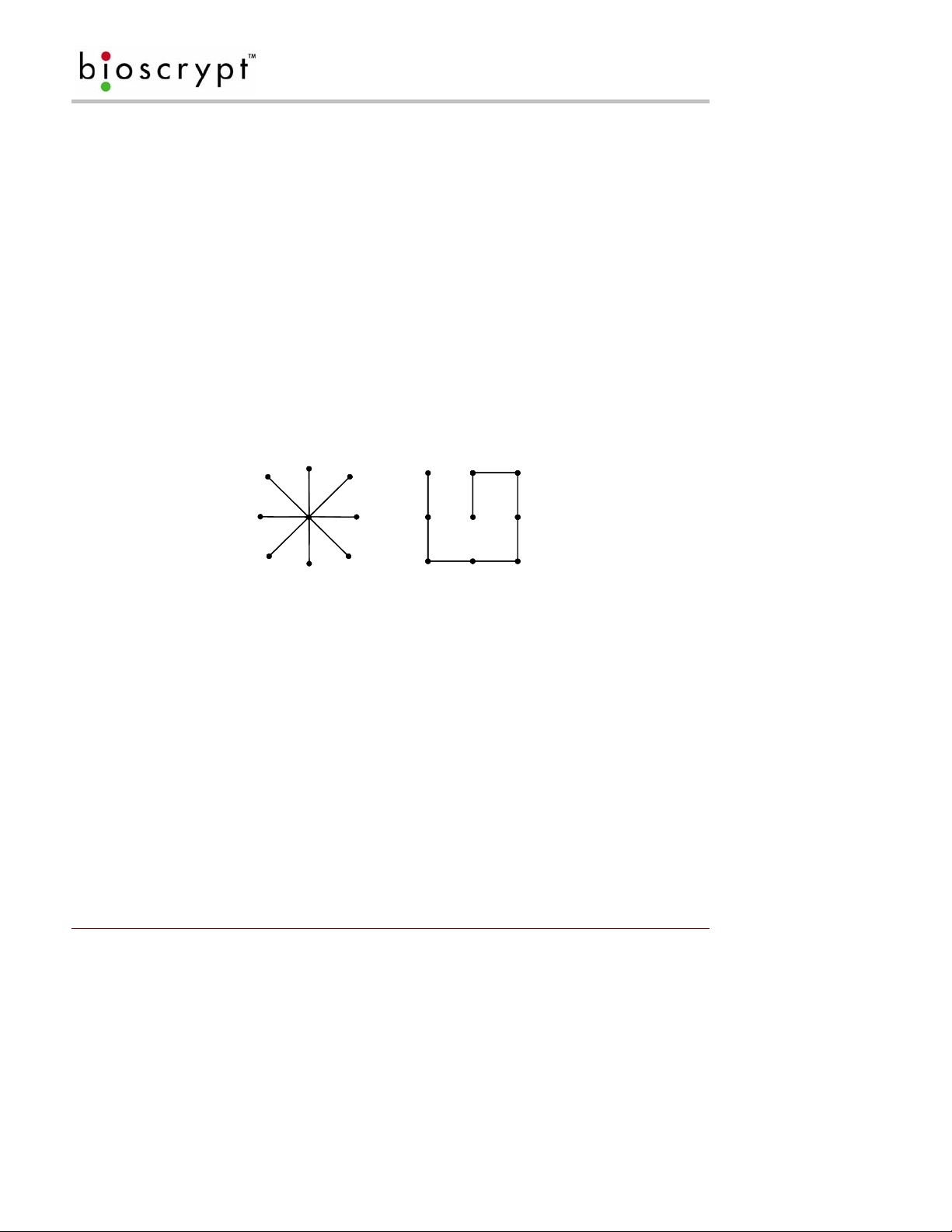
7.3.2 RS-485 Network Topology
Communication cables for RS-485 should be laid out in a daisy chain (See Figure 4). Long stubs or drop downs
(See 7.5 Cable lengths) and the star configuration should be avoided because they create discontinuities and
degrade signal quality. The star configuration usually does not provide a clean signaling env ironment even if the
cable runs are all of equal length. The star configuration also presents a termination problem, because
terminating every endpoint will overload the driver. Terminating only two endpoints so lves the loading problem
but creates transmission-line problems at the un-terminated ends. A true cascade or daisy chain connection
avoids these problems.
Figure 4: Network Topologies - Star and Cascade (Daisy Chain)
7.3.3 Extending the RS-485 Specification
Some systems require longer distances or higher numbers of nodes than supported by RS-485. Repeaters are
commonly used to overcome these barriers. An RS-485 repeater can be placed in a system to divide the load
into multiple segments. Each refreshed signal is capable of driving another 1200 meters (4000 feet) of cable
and an additional 31 RS-485 reader loads. The PIV-Station readers represent a single reader load to the
transmission line.
7.4 Ethernet Networks
If your system will be configured for use over Ethernet, the wiring will be slightly different. Communication
cables for Ethernet logically form a straight line bus but the more devices on that bus the less efficient the
network becomes due to increased collisions and the weaker the signal will get over distance. Repeaters can
be used to boost the signal strength however a better solution is to place switches at intermediate positions
along the bus. The most common Ethernet topology in use today is the star configuration (See Figure 4) with a
hub or switch in the center.
Part # 430-00186-00 ©Copyright 2007, Bioscrypt Inc.
PIV-Station Installation Guide All rights reserved.
11

INSTALL SOFTWARE
8 Install Software
8.1 System Requirements
The following system requirements must be met for VeriAdmin Management Software to properly work:
• 30 MB hard-drive space
• 16 MB of RAM minimum
• CD-ROM Drive
• COM port and / or USB port
• V-Station CNV kit (RS-232/RS-485 converter) if RS-485 is to be used
• Windows 2000 or Windows XP (recommended by Bioscrypt)
8.2 Install Software
1. Log into the PC as any user with Admini stra t i v e privileges.
2. Insert the installation CD in to the CD-ROM drive.
3. InstallShield Wizard should start.
4. If you downloaded the software or install does not start, locate and double click on the Setup.exe file.
5. Step through the wind ows choosing to accept the default settings if possible.
6. You may accept the default path C:\Program Files\Bioscrypt\VeriAdmin or an alternate directory.
7. The installer prompts, “Do you want to remove the Fingerprint Image and Template Data?”. Click Yes
to install the FPF feature or No to disable this feature. The installer will prompt, “Are you sure?” click
OK. Note that this will only affect non-PIV-Station readers used on this same install of VeriAdmin and
will not affect any features of the PIV-Station.
8. Allow the installation to complete.
9. Launch VeriAdmin, if the message VeriAdmin was not able to read from the Windows registry is
seen, log off PC, log on with Administrative privileges, and repeat steps one to eight.
VeriAdmin Management Software is no longer supported on the following
platforms: Windows 95
TM
, Windows 98TM, Windows NTTM, and Windows ME
Bioscrypt does NOT accept responsibility for any issues with VeriAdmin
Management Software Installations that may arise from use on unsupported
platforms or platforms not mentioned in this document.
TM
.
8.3 Re-installing or Updating Software
1. Log into the PC as any user with Admini stra t i v e privileges.
2. Make a back up copy of the C:\Program Files\Bioscrypt\VeriAdmin folder to another folder.
3. Insert the installation CD in to the CD-ROM drive.
4. Install Shield Wizard should start.
5. If you downloaded the software or install does not start, locate and double click on the Setup.exe file.
6. The software will prompt you to first remove the previous version, click OK to proceed.
7. Step through the wind ows choosing to accept the default settings if possible.
8. You may accept the default path C:\Program Files\Bioscrypt\VeriAdmin or an alternate directory.
9. The installer prompts, “Do you want to remove the Fingerprint Image and Template Data?”. Click Yes
to install the FPF feature or No to disable this feature. The installer will prompt, “Are you sure?” click
OK. Note that this will only affect non-PIV-Station readers used on this same install of VeriAdmin and
will not affect any features of the PIV-Station.
10. Allow the installation to complete.
11. The template and network configuration (UNITIDS.DAT) files must be copied from the backup folder
made in step 2 to the new C:\Program Files\Bioscrypt\VeriAdmin folder.
12. Launch VeriAdmin, if the message VeriAdmin was not able to read from the Windows registry is
seen, log off PC, log on with Administrative privileges, and repeat steps one to eleven.
Part # 430-00186-00 ©Copyright 2007, Bioscrypt Inc.
PIV-Station Installation Guide All rights reserved.
12

INSTALL SOFTWARE
8.4 Post-Install Software Configuration
Once the installation is complete, a shortcut icon (See Figure 5) for the Administration Software will appear on
your desktop. This icon will also be found under Start Menu > Program Files > Bioscrypt> VeriAdmin.
Figure 5: VeriAdmin desktop icon
When you launch the software you will see one of two possible welcome screens.
• If re-installing or updating VeriAdmin, you will see the dialog shown below (See Figure 6). This
message indicates that VeriAdmin has found the old network configuration file (UNITIDS.DAT).
VeriAdmin will take advantage of your previous work and import this file for you if you click Yes.
Selecting this option will bring up the Network Configuration Manager. Refer to the Operator’s Manual
for more information.
Figure 6: VeriAdmin Welcome Message (Update)
• If installing VeriAdmin for the first time, you will see the welcome message below (See Figure 7). This
message is simply informing you that this is the first time the software has been installed and that all the
necessary files have been created. Contact Bioscrypt Technical Support for troubleshooting assistance
if this is not the first time you have installed this software.
Figure 7: VeriAdmin Welcome Message (New Install)
Part # 430-00186-00 ©Copyright 2007, Bioscrypt Inc.
PIV-Station Installation Guide All rights reserved.
13

INSTALL SOFTWARE
8.5 USB Driver Install
V-Station products feature a USB interface for the Aux port, utilizing a Serial-to-USB converter (CP210x USB to
UART Bridge). In order to use this interface, the proper drivers must be installed. You should install the drivers
BEFORE attaching any of the Readers to your computer's USB port for the first time.
1. Log into the PC as any user with Admini stra t i v e privileges.
2. Locate the folder USB_Driver_CP210x_Bridge on the installation CD.
3. Double-click the file CP210x_VCP_Win2K_XP.exe and follow the prompts in the Wizard.
4. After the driver is installed, later connecting the first Reader to the computer will auto-locate the driver.
5. If the driver is not located you may be prompted to browse to the drivers in folder
C:\SiLabs\MCU\CP210x\Win2K_XP.
Comment [D2]: Are we fixing this
installer in this version?
Part # 430-00186-00 ©Copyright 2007, Bioscrypt Inc.
PIV-Station Installation Guide All rights reserved.
14
CONFIGURE PORTS
9 Configure Ports
Bioscrypt PIV-Station readers communicate with the VeriAdmin software through the Host port or the USB
Auxiliary (USB) port. Cables can be connected to either of the ports on the PIV-Station reader, but the reader
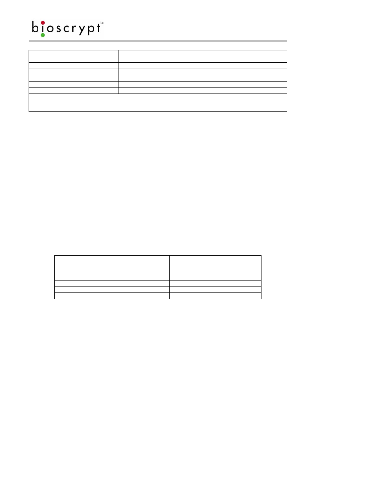
can communicate through only one port at a time. The default settings are shown in Table 3.
V-Station Factory Defaults
Network ID: 0
Port Mode: N/A (defaults to RS-232 for Host)
Host Port Protocol: RS-232
Host Port baud rate: 57600 baud
Aux Port baud rate: 57600 baud
IP Address: 0.0.0.0
Table 3: Factory Settings
The PIV-Station uses RJ-45 and RJ-11 connections at the rear of the reader for RS-485 and RS-232
respectively or these can be connected via the Weidmuller connector. The Host port can be either RS-232 or
RS-485 as discussed in Section 7. This option is configured in the PIV-Station Port Mode section of
Communication tab in the Unit Parameters dialog of VeriAdmin. After installing the software the ports are
configured by following the instructions below (to return to this screen later and for more information, see the
Operator’s manual).
1) Close the Welcome screen by clicking OK.
2) The network settings screen will appear as shown in Figure 8.
3) Do not choose Ethernet unless you are using the Ethernet port.
4) Indicate which ports to use by clicking the Use box (by default all available ports are selected).
5) Select the desired Port.
6) Baud rate can be set manually or by automatic detection.
a. NOTE: The Auto option should not be used for RS-485. Manually set the Reader to the proper
baud rate.
b. Initially set the baud rate to the defaults as shown in Table 3 above to allow start up
communication. These can be changed later if desired.
c. If you know the baud rate, enter it for speed of set up even if using Auto as it is used for
7) After selecting which serial ports to use, click OK.
broadcasts.
Part # 430-00186-00 ©Copyright 2007, Bioscrypt Inc.
PIV-Station Installation Guide All rights reserved.
15

CONFIGURE PORTS
Click the Use checkbox to
enable a COM port for serial
The Auto checkbox will auto-negotiate
baud rates, except when broadcasting
communication.
over an RS-485 network.
Figure 8: Network Setup dialog
Part # 430-00186-00 ©Copyright 2007, Bioscrypt Inc.
PIV-Station Installation Guide All rights reserved.
16

CONNECT READER FOR CONFIGURATION
10 Connect Reader for Configuration
Once the ports are set up, the readers will need to be configured before being added to the network.
In this section you will:
• Configure the reader using the USB port and a PC
• Set Unit Network ID to a unique number
• Set Host Port Protocol
• Set Host Port Baud Rate
10.1 Initial Reader Setup
1. When you click the OK button on the Network Setup Screen (in Section 9 Step 7).
2. The Network Configuration Manager dialog will appear. See Figure 9.
3. Supply power to the proper connectors on the rear of the PIV-Station Reader (Refer to Table 5 for a
wiring diagram).
4. When power is applied, the front LED will glow blue, and the top LED will blink amber, and then turn
off (It will remain on for Readers configured to 1:N ).
5. Connect the Reader’s USB bottom port to your PC’s USB port using the USB programming cable
provided with the Reader.
6. Check the USB com port as described in Section 10.2 if this is the first use of it.
7. Once a Reader is connected, you can now set the Network ID on the reader. Double-click on the
icon for that Reader in the Network Tree, bringing up the Unit Parameters dialog.
8. In the Communication tab, type the desired ID number in the Assign Unit Network ID field. Press
the Apply button to make the change. Note this will change the Network ID in fl ash on the reader
and will also modify the Transmit ID that is being used by the PC so that you may continue to
communicate. The General tab of this dialog box shows the current communication settings.
9. Select the appropriate baud rate from the Host Port Baud Rate dropdown list. Keep in mind that
you are currently talking over the USB port, but you are changing the Host Port settings that will be
used when you connect to the Reader through the Host Port wires on the back of the Reader.
10. The PIV-Station Host Port parameter, in the Communication tab in the Unit Parameters dialog in
VeriAdmin, will allow the user to select the desired Host port. Options are Protocol (Either RS-485
or RS-232) and Baud Rate.
11. If this reader is being configured for Ethernet, click the Advanced button in the Advanced settings
window. This will launch a window from which you can set the IP address and TCP port.
12. Select the COM port to which you are adding a Reader and click ADD UNIT.
13. Enter the Transmit ID that will be used for this Reader and a name if desired.
14. Click Refresh.
15. Repeat steps 3 through 14 for each Reader being added.
As with all removable USB hardware, care must be taken to properly stop the
device before unplugging to avoid hanging the software. Bioscrypt recommends
the following sequence of steps when temporarily using the USB Aux port to
communicate with a VeriSeries reader:
1. Physically connect the reader to the PC via USB
2. Open VeriAdmin
3. Perform necessary operations
4. Close VeriAdmin
5. Disconnect Reader
Part # 430-00186-00 ©Copyright 2007, Bioscrypt Inc.
PIV-Station Installation Guide All rights reserved.
17
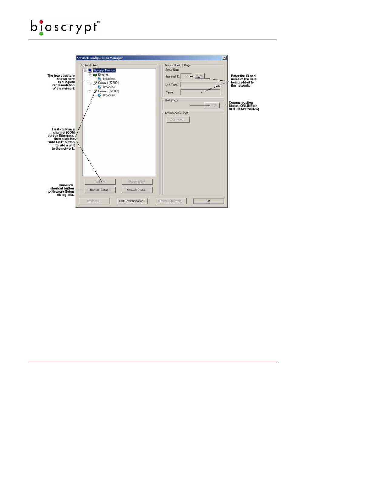
CONNECT READER FOR CONFIGURATION
Figure 9: Network Configuration dialog
10.2 Check USB COM port.
1. Confirm Reader is connected to power.
2. Connect USB cable to reader then connect it to the PC.
3. The new hardware will be found and Add Hardware Wizard will launch.
4. Select No, not at this time then click Next.
5. Select Search for the best driver in these locations.
6. Uncheck Search removable media.
7. Check Include this location in the search - C:\SiLabs\MCU\CP210x\Win2K_XP.
8. Click Next.
9. This will find the driver and install it.
10. The system will find the new hardware again and Add Hardware Wizard will launch.
11. Follow steps 4 to 8 again.
12. Go to Device Manager and confirm COM port number assigned to Reader.
13. If you can locate either of the drivers below skip to Step 23. If not, skip to step 14.
a. CP210x USB to UART Bridge Controller [in Ports (COM & LPT)].
b. CP210x USB Composite Device [in Universal Serial Bus Controllers].
14. Look at the Other Devices category as an Unknown Device.
15. Double-click on the unknown device.
16. Click on the Driver tab.
17. Click Update driver.
18. The Hardware Update Wizard will appear.
19. Select Install from a list or specific location (Advanced).
Part # 430-00186-00 ©Copyright 2007, Bioscrypt Inc.
PIV-Station Installation Guide All rights reserved.
18

CONNECT READER FOR CONFIGURATION
20. Click Next.
21. Select Search for the best driver in these locations.
a. Uncheck Search removable media (floppy, CD-ROM…).
b. Check Include this location in the search.
c. Click Browse, select C:\SiLabs\MCU\CP210x\Win2K_XP.
d. Click OK.
e. Click Next.
22. Click Finish.
23. Once the COM port is created, double click it and select port settings.
24. Verify that the bits per second setting is set to 57600.
25. Click OK when done.
Part # 430-00186-00 ©Copyright 2007, Bioscrypt Inc.
PIV-Station Installation Guide All rights reserved.
19

MOUNTING
11 Mounting
11.1 Mounting Readers
The PIV-Station readers are designed to mount on either a double-gang electrical box or any flat surface.
Consult with local professionals regarding the building and safety codes that will affect your installation.
Bioscrypt provides wall plate for these applications. The following section describes the proper PIV-Station
mounting. The mounting plate is detailed below in Figure 10.
Factors in determining the position of the reader on the wall should include mounting in-line with other switch
plates or fixtures, approximately 54 inches from floor to top of reader, mounted on knob-side of door, and in
accordance with the A m eri cans with Disabilities Act
48 – 54”
.
Figure 10: Mounting Height
All of the PIV-Stations and mounting plates are constructed out of durable ABS plastic. This system provides for
a very lightweight, yet sturdy system.
11.2 Mounting Templates
• For mounting into wall anchors, wood or sheet metal use #4 flat head screws (<0.125 inch thre ad width,
<0.250 inch head width).
• For mounting onto gang box, use #6-32 machine screws with flat head.
• All dimensions are in mm unless noted.
• Refer to Figure 13 for image of the PIV-Station mounting plate.
• Leave wires accessible for wiring of reader later.
• The Weidmuller connector will protrude approximately 24 mm (1 inch) past the wall plate and into the
wall (depending on the connectors attached).
• The ac cess hole must be at least the size of the hole in the wall pl ate (136mm (~5 3/8”) wide b y 69mm
(~2 ¾”) tall). Trace the edges of the hole in the wall plate in pencil before cutting.
11.3 Attaching Reader to Mount
Reader mounting is very simple when the time comes (See Section 12). T he mounting plate (See Figure 12) is
attached using screws and anchors to secure it in place. The reader body has tabs that slide into the wall plate .
Part # 430-00186-00 ©Copyright 2007, Bioscrypt Inc.
PIV-Station Installation Guide All rights reserved.
20

MOUNTING
Use the following procedure. Mounting is shown in Figure 11 below (V-Pass FX mount shown but procedure is
same).
1. Align reader body with wall plate.
2. Slide reader body down, locking tabs into wall plate.
3. Set reader body in place with Phillips-head #4-40 screw.
4. Attach Aux. port door to bottom of reader with a twisting motion.
5. Secure door to reader with pin-in-hex #6-32 screw.
6. Secure reader to bracket with second pin-in-hex #6-32 screw on bottom right.
Figure 11: Mounting Procedures
Part # 430-00186-00 ©Copyright 2007, Bioscrypt Inc.
PIV-Station Installation Guide All rights reserved.
21

MOUNTING
Comment [D3]: Replace this one
with the two for PIV
Figure 12: PIV-Station Mounting Template
Part # 430-00186-00 ©Copyright 2007, Bioscrypt Inc.
PIV-Station Installation Guide All rights reserved.
22
POWER DISTRIBUTION & READER HOOKUP
12 Power Distribution & Reader Hookup
Each of the PIV-Station readers offers RS-232, RS-485, and USB communication channels for communicating
with a PC or host controller. Each reader also uses the Wiegand protocol to interface with Access Control
equipment, such as access controllers (outputs) or additional readers (inputs). The PIV-Station produc t will rely
on power provided to the system for operation. In a small installation, power may be provided by means of an
AC adapter placed near the PIV-Station reader itself. In larger installations, power will be distributed from either
a central source or various sources.
12.1 V-Station Power
Power to the PIV-Station readers should be:
• Isolated from other equipment.
• Filtered.
• Protected by means of an uninterruptible power supply (UPS) or battery backup.
• If transient electrical surges are an issue in the location, a voltage suppression device is also
recommended.
When planning a system, know the power requirement of each reader. If multiple readers are to share a
common power supply, care must be exercised to avoid excessive voltage loss on the wires. Vol tage loss can
lead to communication problems when readers are talking and/or listening on different ground references.
Voltage loss is directly proportional to wire resistance and the current the wire carries. Place the power supply
as close to the equipment as possible. Select appropriate wire size for the load. The PIV-Station readers run
on DC power between 12.5 and 24 VDC. Power requirements are as listed in Table 4.
V-Station (all models)
Power Requirement:
Input Voltage Range:
Peak Current:
12 watts
12.5-24.0 VDC
12 VDC 1 A
24 VDC 500 mA
Table 4: PIV-Station Power Requirements
12.2 Selecting the Right Power Supply
Most power supplies in the market today provide good input/output isolation, however those which do not
provide isolation (or have high leakage capacitance), coupled with accidental AC power line interchange,
present serious ground fault problems for installers. With ground fault, the signal reference between
subsystems may be 115 VAC apart. If these subsystems are interconnected, the large potential difference will
cause equipment damage or personal injury. We recommend only the use of a 12.5 VDC, 1 A, isolated, ULListed Class II power supply.
All factory supplied power supply assemblies are either switching or regula ted linear supplies and are isolated
for safety and to minimize ground loop problems.
Part # 430-00186-00 ©Copyright 2007, Bioscrypt Inc.
PIV-Station Installation Guide All rights reserved.
23

POWER DISTRIBUTION & READER HOOKUP
The readers are connected to other components of an integrated system through the rear of the reader. This is
made up of the connections described in Table 5.
Pin Group Label Signal Description
8-Pin Connector:
1 TX(+) Transmit +
RS-485
2 TX(-) Transmit 3 RX(+) Receive +
4 RX(-) Receive 5
6 GND RS-232 Signal Ground
RS-232
GND RS-485 Signal Ground
7 TX Transmit
8
RX Receive
3-Pin Connector:
1 +(POS) 12.5 – 24 VDC +
Power/Ground
2 -(NEG) 12.5 – 24 VDC 3
EGND Earth Ground
12-Pin Connector:
1 IN 0 Data 0 In
Wiegand
2 IN 1 Data 1 In
3 OUT 0 Data 0 Out
4 OUT 1 Data 1 Out
5 LED IN LED In
6 LED OUT LED Out
7
8 IN 0 TTL Data 0 In
TTL (IN)
9
10 Out 0H TTL Data 0 Out
TTL (OUT)
GND Wiegand Ground
IN 1 TTL Data 1 In
11 OUT 1L TTL Data 1 Out
12
GND TTL Ground
Table 5: PIV-Station Weidmuller Connections
Comment [D4]: Check these.
Part # 430-00186-00 ©Copyright 2007, Bioscrypt Inc.
PIV-Station Installation Guide All rights reserved.
24

POWER DISTRIBUTION & READER HOOKUP
Figure 13: PIV-Station Reader Pin Out (Reader Back View)
Part # 430-00186-00 ©Copyright 2007, Bioscrypt Inc.
PIV-Station Installation Guide All rights reserved.
25
Comment [D5]: Needs update?

POWER DISTRIBUTION & READER HOOKUP
Group PIN Signal
Ethernet RJ-45 1 Receive +
2 Receive 3 Transmit +
4 NC
5 NC
6 Transmit 7 NC
8 NC
RS-485 RJ-45 1 Transmit +
2 Transmit 3 Ground
4 Receive +
5 Receive 6 NC
7 NC
8 NC
RS-232 RJ-11 1 TX
2 RX
3 RTS*
4 CTS*
5 Ground
6 NC
Table 6: PIV-Station Ethernet, RJ-45, and RJ-11 Connections
*Not connected but may be used in the future.
Part # 430-00186-00 ©Copyright 2007, Bioscrypt Inc.
PIV-Station Installation Guide All rights reserved.
26

POWER DISTRIBUTION & READER HOOKUP
12.3 Wiegand Connections
Wiegand output lines should be connected to a Wiegand compatible controller. When connecting Wie gand
output to a controller, you must make sure that the connection is using Data0, Data1, and a common Ground
reference. See Table 5 above for the wiring of the Wiegand and Figure 14 for the l ayout on the back of the PIVStation.
12.4 ESD Shield Earth Ground Requirement
The finger mask (conductive plastic surrounding the finger-scan sensor) is sometimes referred to as an ESD
Shield. The cable (14-18 AWG) that should be used for the ESD Shield is dependent on length. EGND on the
unit should be connected in a direct (homerun) configuration to a solid Earth Ground such as a cold water
copper pipe or a building ground. See Section 2 for details. Do not connect the ESD Shield to Power
Ground! The solid Earth Ground connection chosen should measure less than 4 ohm resistance when
measured against a known Earth Ground.
12.5 RS-485
RS-232, RS-485, and USB can be used for communication with a PC running PIV-Station c ompatible software
(such as our VeriAdmin software). RS-232 and USB communication is only used for a single reader at a time.
If readers are networked, RS-485 connection protocol must be used. Fo r a PC that is administering a RS-485
network, a RS-232 to RS-485 converter is required. RS-485 connections among various readers should be
made by connecting the (+) and (-) lines of the differential RS-485 in a daisy chain manner. For instance, from
V-Prox to V-Prox, the (+) line from one V-Prox is connected to the (+) line of the ne xt V-Pro x an d s o on; l ike wise
for the (-) lines. Additionally, connect the grounds from each V-Prox reader back to the signal ground
connection for the PC. Figure 14 below shows the wiring of an RS-232 to RS-485 converter (Shown with
optional VeriSeries readers for reference.).
Figure 14: Wiring Diagram for RS-232 to RS-485 Converter
12.6 Network Operation Issues:
• Use Category 5 cabling for a RS-485 network.
• Choose one twisted pair of conductors to use for RS-485 differential connection, other conductors
should be used for Signal Ground (RS-485 GND on Weidmuller connection).
• RS-232/RS-485 Converter must support sense data to switch from send to receive mode.
o Check each reader/cabling for ground fault before connecting to RS-485 network.
o Each reader should have its ESD Shield Ground (EGND) connected to Earth Ground.
o Once all readers are configured and connec ted to the RS-485 network, the baud rate can be
increased to highest supported rate (some experimentation required).
• Reader will return a busy signal (error –104) if communication cannot be processed due to current
processing – usually enroll or verify.
Part # 430-00186-00 ©Copyright 2007, Bioscrypt Inc.
PIV-Station Installation Guide All rights reserved.
27

SYSTEM TURN-UP PROCEDURES
13 System Turn-Up Procedures
System turn-up must follow a step-by-step procedure to avoid difficult troubleshooting. Never wire up a system
and apply power to it all at once.
13.1 System Turn up Overview
The following steps should be followed in order:
1. Do not apply power to any readers.
2. Check all wiring and reader configurations.
3. Disconnect all readers from communication line.
4. Check the supply voltage for correct voltage.
5. Power up the PC running the PIV-Station software.
6. Power up the RS-232 to RS-485 converter (if installed).
7. Configure the PC softw are.
8. Complete ground fault check in Paragraph 13.3 below for the converter (if installed).
9. Connect the PC and converter (if installed) to the communication line.
10. Verify that a reader powers up correctly, but DO NOT connect it to the communication line.
11. Complete ground fault check for this reader in Paragraph 13.4 below (if using RS-485).
12. Connect this reader to the communication line.
13. Verify that it communicates with the PC software.
14. If there are more readers, add the subsequent readers by repeating steps 10-13.
13.2 Reader Configuration Check
Readers must be configured correctly before they can communicate. Common problems include not correctly
selecting the correct HOST Port, failure to change mode setting to RS-485 (when used), mismatched baud
rates, and incorrect Unit Network ID. Each reader sharing the communication line must have a unique Unit
Network ID.
13.3 Ground Fault Converter Check
Before a reader is connected to an RS-485 subsystem, it must be checked for ground fault. An uncorrected
ground fault can damage all readers connected to the RS-485 communication line.
To check if there is ground fault on the RS-232 to RS-485 converter, follow the steps below:
1. Apply power to the RS-232 to RS-485 converter.
2. Connect the signal ground of the RS-485 line through a 10-kΩ current limiting resistor to the signal
ground of the RS-232 to RS-485 converter.
3. There should be no more than 1 volt across the resistor. Otherwise find and clear the fault.
13.4 Ground Fault Reader Check
To check if there is ground fault for a new reader, follow the steps below:
1. Apply power to all readers already successfully connected to the RS-485 line.
2. Power up the new reader but DO NOT connect it to the RS-485 line.
3. Connect the signal ground of the RS-485 line through a 10-kΩ current limiting resistor to the signal
ground of the PIV-Station reader.
4. There should be no more than 1 volt across the resistor. Otherwise find and clear the fault.
5. Repeat the steps in 1 to 3 with each of the RS-485 signal lines (+ and –).
6. Connect the new reader to the RS-485 line only if no ground fault is found.
Part # 430-00186-00 ©Copyright 2007, Bioscrypt Inc.
PIV-Station Installation Guide All rights reserved.
28

USER INTERFACE
14 User Interface
Once the system is installed using the PIV-Station is a simple procedure.
1. On the Contactless model, users simply place their PIV card on the reader.
2. On the Contact reader model, initiate verifications by inserting the PIV card into the reader.
o The unit will prompt for PIN.
o When the screen says Place Finger they may then place their finger.
3. The LCD will then say either “Accepted” (top LED will turn green) or “Rejected” (top LED turns red).
o If accepted, the verification actions specified by the administrator will be executed.
o If rejected, the reader returns to its idle state.
4. When reader returns to idle state, the top LED will turn off.
1.1. Consistent Finger Placement
One key to trouble-free finger-scan recognition is consistent finger placement.
Bioscrypt has designed the Ridge-Lock to create simple user instruction and consistent finger position. The
pictures below show the V-Prox FX but the procedure is the same.
1. Wait for the amber light (LED) to be illuminated.
Figure 15: Amber LED
2. With the fingertip raised rest the tip on the Ridge-Lock at a right angle.
Figure 16: Fingertip on Ridge-Lock
3. Slide the finger across the Ridge-Lock keeping the fingertip raised so as not to touch the sensor.
Figure 17: Slide Finger Across Ridge-Lock
4. Position the finger where the first joint of the finger meets the Ridge-Lock
Part # 430-00186-00 ©Copyright 2007, Bioscrypt Inc.
PIV-Station Installation Guide All rights reserved.
29

USER INTERFACE
Figure 18: Position Finger on Sensor
5. Lower the finger onto the sensor and apply moderate pressure as if pressing a computer key. Too
much pressure may cause smudging of the fingerprint. Too little pressure may not allow the sensor to
recognize the presence of a finger.
Figure 19: Apply Correct Pressure
6. Keep the finger on the sensor until the top LED turns green.
Figure 20: Wait for Green LED
7. Lift the finger up and off the sensor.
Figure 21: Lift Finger Up and Off Sensor
8. Have the user practice this a few times before enrollment so that they can have a feel for how they
should use the reader on a daily basis. The goal is to have consistent placement so the PIV-Station
Reader sees approximately the same information each time.
1.2. Proper Finger Orientation
Part # 430-00186-00 ©Copyright 2007, Bioscrypt Inc.
PIV-Station Installation Guide All rights reserved.
30

USER INTERFACE
Cover the entire area of the sensor with the fingertip to provide the most information.
Figure 22: Cover Entire Sensor
Do not touch the sensor as if pressing a button or it will create an image that lacks core data.
Figure 23: Incorrect Placement
Place the finger as close to the center position of the sensor to increase acceptance rate.
Figure 24: Place Finger Close to Center
Finger rotation should be kept to a minimum during enrollment and verification/identification
Part # 430-00186-00 ©Copyright 2007, Bioscrypt Inc.
PIV-Station Installation Guide All rights reserved.
31

USER INTERFACE
Figure 25: Do Not Rotate Finger
Part # 430-00186-00 ©Copyright 2007, Bioscrypt Inc.
PIV-Station Installation Guide All rights reserved.
32

USER INTERFACE
1.3. Center the core
A finger core is the area located within the inner most re-curving ridge. Normally it is located in the middle of
the finger. When enrolling, place the finger on the sensor where the entire core can clearly be seen in the
Fingerprint Image window. The green dots represent the center of the core. Every attempt should be
made to ensure that the core is positioned in the center of the captured image.
Arches (plain and tented)
Figure 26: Finger Core
Loops (singular and twinned)
Whorls and Central Pocke t Loops
Part # 430-00186-00 ©Copyright 2007, Bioscrypt Inc.
PIV-Station Installation Guide All rights reserved.
33

APPENDIX A: NOTICES
15 Appendix A: Notices
The PIV-Station product line has been tested for compliance with all applicable international standards. The
resulting approvals are listed below, and are additionally printed on the labeling located on the rear panel of the
product.
The power supply offered by Bioscrypt is CE approved and UL listed.
V-Station, U, G, R
V-Station, U, GC, R
V-Station, U, G, GC, R
15.1 FCC Information to Users
This equipment has been tested and found to comply with the limits for a Class A digital device, pursuant to Part
15 of the FCC Rules. These limits are designed to pr ovide reasonable protection against harmful interference
when the equipment is operated in a commercial environment. This equipment generates, uses, and can
radiate radio frequency energy and, if not installed and used in accordance with the i nstruction manual, may
cause harmful interference to radio communications. Operation of this equipment in a residential area is likely
to cause harmful interference in which case the user will be required to correct the interference at their own
expense.
15.2 FCC Class B Unintentional Radiators
This equipment has been tested and found to comply with the limits for a Class B digital device, pursuant to Part
15 of the FCC Rules. These limits are designed to provide reasonable protection against harmful interference in
a residential installation. This equipment generates, uses, and can radiate radio frequency energy and, if not
installed and used in accordance with the instruction manual, may cause harmful interference to radio
communications. However, there is no guarantee that interference will not occur in a particular installation. If
this equipment does cause harmful interference to radio or television reception, which can be determined by
turning the equipment off and on, the user is encouraged to try to correct the interference by one of more of the
following measures:
• Reorient or relocate the receiving antenna;
• Increase the separation between the equipment and receiver;
• Connect the equipment into an outlet on a circuit different from that to which the receiver is connected;
• Consult the dealer or an experienced radio/TV technician for help.
Warning
operate the eq uipment.
: Changes or modifications not expressly approved by Bioscrypt Inc. could void the user’s authority to
15.3 CE Information to Users
All PIV-Stations readers have the CE mark, for compliance with CISPR22 /EN 55022 requirements. For
European Union (EU) countries, PIV-Station, U, G, R and PIV-Station, U, GC, R and PIV-Station U, G, GC, R
are compliant with CE under the R&TTE Directive, related to the radio transceivers that are part of their design.
More information can be found regarding the CE R&TTE directive online at the European Union web site:
http://www.europa.eu.int/comm/enterprise/rtte/index.htm
Part # 430-00186-00 ©Copyright 2007, Bioscrypt Inc.
PIV-Station Installation Guide All rights reserved.
34

APPENDIX A: NOTICES
15.4 V-Station,U,G,R; V-Station,U,GC,R; V-Station,U,G,GC,R: Information for Users
The PIV-Station, U, G, R and PIV-Station, U, G, GC, R shall include an embedded Gemplus Gemprox C2
MIFARE contactless smart card reader. This device shall be a radio-tranciever with the following
characteristics:
• Operating Frequency Range: 13.553 – 13.567 MHz
• RF Power Rating: 0.0 Watts
• RF Output Impedence: 50 Ohms
Part # 430-00186-00 ©Copyright 2007, Bioscrypt Inc.
PIV-Station Installation Guide All rights reserved.
35

APPENDIX B: E. U. CERTIFICATION
DOCUMENTATION
16 Appendix B: E. U. Certification Documentation
This appendix contains data related to the PIV-Station product line regarding the test procedures and
Declarations of Conformity as required under the R&TTE directive by the European Union for all devices
containing radio transmitters. The following Bioscrypt products contain radio transmitters:
Name Model Number
V-STATION, U, G, R V-Stn, U, G, R
Hereby, Bioscrypt declares that the PIV-Station, A, P, R and PIV-Station, A, G, R are in compliance with the
essential requirements and other relevant provisions of Directive 1999/5/EC.
16.1 Restrictions of Use
16.1.1 V-Station, U, G, R and PIV-Station, U, GC, R and PIV-Station, U, G, GC, R
Bioscrypt has notified and gained approval to sell the PIV-Station, A, P , R a nd PIV-Statio n, A, G, R in all
EU countries except
except the following for the PIV-Station, U, G, R and PIV-Station, U, GC, R and PIV-Station, U, G,
GC, R readers:
• Bulgaria
• Croatia
• Romania
For latest product approval status and updates, please refer to the Bioscrypt web page at:
http://www.bioscrypt.com
V-STATION, U, G, GC, R V-Stn, U, G, GC, R
the ones listed below. There shall be no restrictions of use in all EU countries
.
Comment [D6]: Update this section
Comment [D7]: Update model
numbers
Part # 430-00186-00 ©Copyright 2007, Bioscrypt Inc.
PIV-Station Installation Guide All rights reserved.
36

APPENDIX B: E. U. CERTIFICATION
DOCUMENTATION
DECLARATION OF CONFORMITY
FOR THE R&TTE DIRECTIVE 1999/5/EC
APPPLICATION OF COUNCIL DIRECTIVE(S): R&TTE Directive 1999/5/EC
MANUFACTURER’S NAME/ADDRESS: Bioscrypt Inc.
505 Cochrane Drive
Markham, Ontario.
Canada L3R 8E3
EUROPEAN REPRESENTATIVE’S Neil McDonald
NAME/ADDRESS: 35 Jackson Crt., Hazlemere, High Wycombe
Buckinghamshire, England
HP157TZ
TEST LABORATORIES: UltraTech EMC Labs Inc. {ITI (UK)) accredited test facilities}
3000 Bristol Circle
Oakville, Ontario, Canada L6H 6G4
EQUIPMENT TYPE/ENVIRONMENT: Short Range Device
TRADE NAME / MODEL NO. : V-Station, A, P, R Model V-Stn, A, P, R
GRANTEE'S NAME: Bioscrypt Inc.
MAXIMUM H-FIELD @ 10m: -0. 6 dBµA/m
TX FREQUENCY RANGE: 124.33 to 127.70 kHz
Rx FREQUENCY RANGE: 124.33 to 127.70 kHz
PRODUCT CLASS: 1 (integral inductive loop antenna with area < 30 m
RECEIVER CLASS: 3
Emission Designation: 2K07P0N
Duty Cycle: ASK 20% duty cycle @ 100 mS (Duty Class: 4)
STANDARD(S) TO WHICH CONFORMITY IS DECLARED:
European Telecommunications Standards Institute (ETSI) ETSI EN 300-330-1 V1. 4. 1 (2005-06) – Electromagnetic
compatibility and Radio spectrum Matters (ERM); Short Range Devices (SRD); Radio equipment in the frequency range 9
kHz to 25 MHz and inductive loop systems in the frequency range 9 kHz to 30 MHz; Part 1: Technical characteristics and
test methods
I, the undersigned, hereby declare that the equipment under test as listed above complies with the applicable
standards as specified by The R&TTE Directive 1999/5/EC.
Manufacturer Legal Representative in Europe
2
)
Shiraz Kapadia Neil McDonald
Vice President Hardware & Operations Director of Sales, EMEA
Markham, ON Canada High Wycombe, England
November 23, 2006 November 23, 2006
Part # 430-00186-00 ©Copyright 2007, Bioscrypt Inc.
PIV-Station Installation Guide All rights reserved.
37

APPENDIX B: E. U. CERTIFICATION
DOCUMENTATION
DECLARATION OF CONFORMITY
FOR THE EMC DIRECTIVE 89/336/EEC
APPPLICATION OF COUNCIL DIRECTIVE(S): EMC Directive 89/336/EEC
MANUFACTURER’S NAME/ADDRESS: Bioscrypt Inc.
505 Cochrane Drive
Markham, Ontario.
Canada L3R 8E3
EUROPEAN REPRESENTATIVE’S Neil McDonald
NAME/ADDRESS: 35 Jackson Crt., Hazlemere, High Wycombe
Buckinghamshire, England
HP157TZ
TEST LABORATORIES: UltraTech EMC Labs Inc. { ITI (UK)) accredited test facilities}
3000 Bristol Circle
Oakville, Ontario, Canada L6H 6G4
EQUIPMENT TYPE/ENVIRONMENT: Short Range Device
TRADE NAME / MODEL NO. : V-Station, A, P, R Model V-Stn, A, P, R
GRANTEE'S NAME: Bioscrypt Inc.
PRODUCT CLASS: 1 (integral inductive loop antenna with area < 30 m
RECEIVER CLASS: 3
MAXIMUM H-FIELD @ 10m: -0.6 dBµA/m
Tx FREQUENCY RANGE: 124.33 to 127.70 kHz
Rx FREQUENCY RANGE: 124.33 to 127.70 kHz
Emission Designation: 2K07P0N
Duty Cycle: ASK 20% duty cycle @ 100 mS (Duty Class: 4
STANDARD(S) TO WHICH CONFORMITY IS DECLARED:
European Telecommunications Standards Institute (ETSI) EN 301 489-1 V1. 6. 1 (2005-09) & EN 301 489-3 V1. 4. 1
(2002-08) – Electromagnetic compatibility and Radio spectrum Matters (ERM); ElectroMagnetic Compatibility (EMC)
standard for radio equipment and services; Part 3: Specific conditions for Short-Range Devices (SRD) Operating on
Frequencies Between 9 kHz and 40 GHz
I, the undersigned, hereby declare that the equipment under test as listed above complies with the applicable
standards as specified by The EMC Directive 89/336/EEC.
Manufacturer Legal Representative in Europe
2
)
)
Shiraz Kapadia Neil McDonald
Vice President Hardware & Operations Director of Sales, EMEA
Markham, ON Canada High Wycombe, England
November 23, 2006 November 23, 2006
Part # 430-00186-00 ©Copyright 2007, Bioscrypt Inc.
PIV-Station Installation Guide All rights reserved.
38

APPENDIX B: E. U. CERTIFICATION
DOCUMENTATION
DECLARATION OF CONFORMITY
FOR THE LOW VOLTAGE SAFETY DIRECTIVE 73/23/EEC
APPPLICATION OF COUNCIL DIRECTIVE(S): Low Voltage Safety Directive 73/23/EEC
MANUFACTURER’S NAME/ADDRESS: Bioscrypt Inc.
505 Cochrane Drive
Markham, Ontario.
Canada L3R 8E3
EUROPEAN REPRESENTATIVE’S Neil McDonald
NAME/ADDRESS: 35 Jackson Crt., Hazlemere, High Wycombe
Buckinghamshire, England
HP157TZ
TEST LABORATORIES: TÜV America Inc.
EQUIPMENT TYPE/ENVIRONMENT: Short Range Device
TRADE NAME / MODEL NO. : V-Station, A, P, R Model V-Stn, A, P, R
GRANTEE'S NAME: Bioscrypt Inc.
PRODUCT CLASS: 1 (integral inductive loop antenna with area < 30 m
RECEIVER CLASS: 3
MAXIMUM H-FIELD @ 10m: -0.6 dBµA/m
Tx FREQUENCY RANGE: 124.33 to 127.70 kHz
Rx FREQUENCY RANGE: 124.33 to 127.70 kHz
Emission Designation: 2K07P0N
Duty Cycle: ASK 20% duty cycle @ 100 mS (Duty Class: 4)
STANDARD(S) TO WHICH CONFORMITY IS DECLARED:
EN 60215: 1996+A1: 1996 – Safety Requirements for Radio Transmitting. However product was tested according
to IEC 60950-1: 2001 (1
st
Edition) and EN 60950-1: 2001/A11: 2004 with reference to Clause 2. 2 SELV Circuits
under CB Report reference No. 095-602924-000
I, the undersigned, hereby declare that the equipment under test as listed above complies with the applicable
standards as specified by The Low Voltage Safety Directive 73/23/EEC.
Manufacturer Legal Representative in Europe
Shiraz Kapadia Neil McDonald
Vice President Hardware & Operations Director of Sales, EMEA
Markham, ON Canada High Wycombe, England
November 23, 2006 November 23, 2006
Part # 430-00186-00 ©Copyright 2007, Bioscrypt Inc.
PIV-Station Installation Guide All rights reserved.
10040 Mesa Rim Road
San Diego, CA 92121
39
2
)

APPENDIX B: E. U. CERTIFICATION
DOCUMENTATION
DECLARATION OF CONFORMITY
FOR THE R&TTE DIRECTIVE 1999/5/EC
APPPLICATION OF COUNCIL DIRECTIVE(S): R&TTE Directive 1999/5/EC
MANUFACTURER’S NAME/ADDRESS: Bioscrypt Inc.
505 Cochrane Drive
Markham, Ontario.
Ontario L3R 8E3
EUROPEAN REPRESENTATIVE’S Neil McDonald
NAME/ADDRESS: 35 Jackson Crt., Hazlemere, High Wycombe
Buckinghamshire, England
HP157TZ
TEST LABORATORIES: UltraTech EMC Labs Inc. {ITI (UK)) accredited test facilities}
3000 Bristol Circle
Oakville, Ontario, Canada L6H 6G4
EQUIPMENT TYPE/ENVIRONMENT: Short Range Device
TRADE NAME / MODEL NO.: V-Station, A, G, R Model V-Stn A, G, R
GRANTEE'S NAME: Bioscrypt Inc.
MAXIMUM H-FIELD @ 10m: -12.3 dBµA/m
Tx FREQUENCY RANGE: 13.56 MHz
Rx FREQUENCY RANGE: 13.56 MHz
PRODUCT CLASS: 1 (integral inductive loop antenna with area < 30 m
RECEIVER CLASS: 3
Emission Designation: 2K88A1D
Duty Cycle: 100%
STANDARD(S) TO WHICH CONFORMITY IS DECLARED:
European Telecommunications Standards Institute (ETSI) ETSI EN 300-330-1 V1.5.1 (2006-04) – Electromagnetic
compatibility and Radio spectrum Matters (ERM); Short Range Devices (SRD); Radio equipment in the frequency range 9
kHz to 25 MHz and inductive loop systems in the frequency range 9 kHz to 30 MHz; Part 1: Technical characteristics and
test methods
I, the undersigned, hereby declare that the equipment under test as listed above complies with the applicable
standards as specified by The R&TTE Directive 1999/5/EC.
Manufacturer Legal Representative in Europe
2
)
Shiraz Kapadia Neil McDonald
Vice President Engineering Director of Sales, EMEA
Markham, ON Canada High Wycombe, England
December 12, 2006 December 12, 2006
Part # 430-00186-00 ©Copyright 2007, Bioscrypt Inc.
PIV-Station Installation Guide All rights reserved.
40

APPENDIX B: E. U. CERTIFICATION
DOCUMENTATION
DECLARATION OF CONFORMITY
FOR THE EMC DIRECTIVE 89/336/EEC
APPPLICATION OF COUNCIL DIRECTIVE(S): EMC Directive 89/336/EEC
MANUFACTURER’S NAME/ADDRESS: Bioscrypt Inc.
505 Cochrane Drive
Markham, Ontario.
Ontario L3R 8E3
EUROPEAN REPRESENTATIVE’S Neil McDonald
NAME/ADDRESS: 35 Jackson Crt., Hazlemere, High Wycombe
Buckinghamshire, England
HP157TZ
TEST LABORATORIES: UltraTech EMC Labs Inc. { ITI (UK)) accredited test facilities}
3000 Bristol Circle
Oakville, Ontario, Canada L6H 6G4
EQUIPMENT TYPE/ENVIRONMENT: Short Range Device
TRADE NAME / MODEL NO.: V-Station, A, G, R Model V-Stn A, G, R
GRANTEE'S NAME: Bioscrypt Inc.
PRODUCT CLASS: 1 (integral inductive loop antenna with area < 30 m
RECEIVER CLASS: 3
MAXIMUM H-FIELD @ 10m: -12.3 dBµA/m
Tx FREQUENCY RANGE: 13.56 MHz
Rx FREQUENCY RANGE: 13.56 MHz
Emission Designation: 2K88A1D
Duty Cycle: 100%
STANDARD(S) TO WHICH CONFORMITY IS DECLARED:
European Telecommunications Standards Institute (ETSI) EN 301 489-1 V1.6.1 (2005-09) & EN 301 489-3 V1.4.1
(2002-08) – Electromagnetic compatibility and Radio spectrum Matters (ERM); ElectroMagnetic Compatibility (EMC)
standard for radio equipment and services; Part 3: Specific conditions for Short-Range Devices (SRD) Operating on
Frequencies Between 9 kHz and 40 GHz
I, the undersigned, hereby declare that the equipment under test as listed above complies with the applicable
standards as specified by The EMC Directive 89/336/EEC.
Manufacturer Legal Representative in Europe
2
)
Shiraz Kapadia Neil McDonald
Vice President Engineering Director of Sales, EMEA
Markham, ON Canada High Wycombe, England
December 12, 2006 December 12, 2006
Part # 430-00186-00 ©Copyright 2007, Bioscrypt Inc.
PIV-Station Installation Guide All rights reserved.
41

APPENDIX B: E. U. CERTIFICATION
DOCUMENTATION
DECLARATION OF CONFORMITY
FOR THE LOW VOLTAGE SAFETY DIRECTIVE 73/23/EEC
APPPLICATION OF COUNCIL DIRECTIVE(S): Low Voltage Safety Directive 73/23/EEC
MANUFACTURER’S NAME/ADDRESS: Bioscrypt Inc.
505 Cochrane Drive
Markham, Ontario.
Ontario L3R 8E3
EUROPEAN REPRESENTATIVE’S Neil McDonald
NAME/ADDRESS: 35 Jackson Crt., Hazlemere, High Wycombe
Buckinghamshire, England
HP157TZ
TEST LABORATORIES: TÜV America Inc.
EQUIPMENT TYPE/ENVIRONMENT: Short Range Device
TRADE NAME / MODEL NO.: V-Station, A, G, R Model V-Stn A, G, R
GRANTEE'S NAME: Bioscrypt Inc.
PRODUCT CLASS: 1 (integral inductive loop antenna with area < 30 m
RECEIVER CLASS: 3
MAXIMUM H-FIELD @ 10m: -12.3 dBµA/m
Tx FREQUENCY RANGE: 13.56 MHz
Rx FREQUENCY RANGE: 13.56 MHz
Emission Designation: 2K88A1D
Duty Cycle: 100%
STANDARD(S) TO WHICH CONFORMITY IS DECLARED:
EN 60215:1996+A1:1996 – Safety Requirements for Radio Transmitting. However product was tested according to
IEC 60950-1:2001 (1
st
Edition) and EN 60950-1:2001/A11: 2004 with reference to Clause 2.2 SELV Circuits under CB
Report reference No. 095-602924-100
I, the undersigned, hereby declare that the equipment under test as listed above complies with the applicable
standards as specified by The Low Voltage Safety Directive 73/23/EEC.
Manufacturer Legal Representative in Europe
Shiraz Kapadia Neil McDonald
Vice President Hardware & Operations Director of Sales, EMEA
Markham, ON Canada High Wycombe, England
December 12, 2006 December 12, 2006
10040 Mesa Rim Road
San Diego, CA 92121
2
)
Part # 430-00186-00 ©Copyright 2007, Bioscrypt Inc.
PIV-Station Installation Guide All rights reserved.
42

APPENDIX C: PRODUCT DOCUMENTS
17 Appendix C: Product Documents
This appendix contains the following product documents in the order listed:
1. Trademark Disclosure
2. Disclaimer
3. Bioscrypt One Year Limited Warranty Policy
4. Bioscrypt Return Policy and Procedures
a. Billable Repair Policy
b. 30 Day Return for Credit
5. Notes
Part # 430-00186-00 ©Copyright 2007, Bioscrypt Inc.
PIV-Station Installation Guide All rights reserved.
43

APPENDIX C: PRODUCT DOCUMENTS
C.1 Trademark Disclosures
Bioscrypt has made every effort to provide disclosures when using trademarks owned by other companies.
Trademarked designations appear throughout this publication. The publisher states that it is using the
designations only for editorial purposes, and to the benefit of the trademark owner with no intent to infringe upon
that trademark. The following trademarks are found in this manual:
• PIV-Station™ is trademarks of Bioscrypt, Inc.
• Microsoft™, Windows 95™, Windows 98™, Windows NT™, Windows ME™, Windows 2000™, and
Windows XP™ are trademarks of Microsoft Corporation.
Part # 430-00186-00 ©Copyright 2007, Bioscrypt Inc.
PIV-Station Installation Guide All rights reserved.
44

APPENDIX C: PRODUCT DOCUMENTS
C.2 Disclaimer
The instructions in this document have been carefully checked for accuracy and are presumed to be reliable.
Bioscrypt Inc. and its writers assume no responsibility for inaccuracies and reserve the right to modify and revise
this document without notice.
It is Bioscrypt’s goal to supply accurate and reliable documentation. If you discover a discrepancy in this
document, please e-mail your comments to support@bioscrypt.com
the telephone number listed below.
No part of this publication may be placed in a retrieval system, transmitted, or reproduced in any way, including,
but not limited to, photograph, photocopy, computer disk or other record, without prior agreement and written
permission from:
Bioscrypt Inc.
2101 Rosecrans Ave, Suite 1250
El Segundo, CA 90245
Phone: 310. 760. 4130
Toll Free: 866. 304. 7180
Web: http://www.bioscrypt.com
Email: support@bioscrypt.com
, or contact Bioscrypt Technical Support at
Part # 430-00186-00 ©Copyright 2007, Bioscrypt Inc.
PIV-Station Installation Guide All rights reserved.
45

APPENDIX C: PRODUCT DOCUMENTS
C.3 Bioscrypt One Year Limited Warranty Policy
Bioscrypt warrants to the original consumer purchaser (“ Customer”) that new Bioscrypt products will be free
from defects in material and workmanship for one year from the date the product was shipped from Bioscrypt.
For replacement products the warranty on the replacement reader is the remainder of the warranty on the
original product or ninety (90) days, whichever is longer. The Customer is resp onsible for mak ing any claims for
shipment damage (evident or concealed) with the freight carrier. Bioscrypt must be notified within thirty days of
shipment of incorrect materials.
If a defect is discovered, Bioscrypt's sole obli gation shall be to repair or replace the Bioscrypt product(s) at its
sole discretion at no charge, provided it is returned to Bioscrypt during the warranty period and is shipped freight
and insurance prepaid. Merchandise must be properly packaged to prevent damage during shipping. Before
returning a Bioscrypt product, contact Bioscrypt Technical Service to obtain a Return Material Authorization
(RMA) number. No product may be returned whether in warranty or out of warranty without first obtaining
approval from Bioscrypt. The model number, invoice number, and serial number may be required for warranty
service.
This warranty shall not apply to any product or any part of a product, which in the judgment of Bioscrypt, has
been subjected to misuse, negligence, alteration, accident, improper maintenance, or damage by excessive
physical or electrical stresses. Tampering, such as opening the housing of a bio metric reader or rep lacing pa rts
will void this warranty. The warranty is void if the serial number of the Bioscrypt product has been defaced,
altered, or removed or if the product has been modified. Repair and replacement parts will be furnished on an
exchange basis and may be either reconditioned or new. All replaced parts or products become the property of
Bioscrypt. This warranty may also be voided for failure to comply with Bioscrypt’s return policy.
The warranty is not applicable to:
• Abnormal wear and tear.
• Damage caused during installation.
• Damage caused by the equipment or system with which the biometric reader is used.
• Damage caused by modifications or repairs not made or authorized by Bioscrypt.
• Damage caused by improper packaging.
• Damage caused by lack of ESD protection.
• Merchandise that is determined to be stolen.
All PIV-Station readers have an operating temperature range of 0°-60° Celsius (32°-140° Fahrenheit). In
addition, the PIV-Station product line has a relative humidit y operating range of 0-95% non-condensing. Any
reader used outside that temperature or humidity range requires an enclosure with thermal or humidity control
that can maintain a consistent environment within the stated operating ranges.
The newest Bioscrypt PIV-Station products are designed to be weather resistant but no sensor technology
exists today that can work in all weather environments. If a Bioscrypt PIV-Station product is not used in a
completely indoor environment, then a protective enclosure is required to shield the reader from moisture, dust,
other contaminants and temperatures outside the stated operating range. Product failures resulting from
exposure to the conditions are not covered under the product warranty.
For outdoor installations, Bioscrypt does offer an enclosure to protect the reader from exposure to moisture,
dust, other contaminants and temperatures outside stated operating range. To maintain the Bioscrypt warranty,
the PIV-Station reader must be installed in a Bioscrypt certified outdoor enclos ure. When used properly, this
enclosure will protect PIV-Station readers in most environments, but not all. The Customer is responsible for
determining whether the offered enclosure will appropriately shield PIV-Station readers in their specific
installation. Products failures resulting from exposure to moisture, dust, other contaminants and temperatures
outside stated operating range, even if an enclosure is used, are not covered under the product warranty.
This warranty is exclusive and in lieu of all others, whether oral or written, expressed or implied. Bioscrypt
specifically disclaims any and all implied warranties, including without limitation, warranties of merchantability
and fitness for any particular purpose. No Bioscrypt dealer, agent, or employee is authorized to make any
modification, extension or addition to this warranty.
Part # 430-00186-00 ©Copyright 2007, Bioscrypt Inc.
PIV-Station Installation Guide All rights reserved.
46

APPENDIX C: PRODUCT DOCUMENTS
C.4 Bi oscrypt Return Policy and Procedures
Bioscrypt must be notified within thirty days of the date that a defect is discovered. Bioscrypt will then issue a
Return Material Authorization (RMA) number which the Customer must include with all correspondence and
display on the outside of the shipping container when returning the product. Any products returned later than 30
days after issuance of an RMA may be subject to review as to whether the authorization to return is still
warranted.
All Bioscrypt products must be shipped freight and insurance prepaid, in the original shipping container or
equivalent. A written description of the defect together with a copy of the invoice and the name of the Dealer
who sold the Bioscrypt product must be shipped with the product. All defects must be reproducible at
Bioscrypt’s location to qualify for this limited warranty.
For shipping addresses and return merchandise authorization contact Bioscrypt Technical Support. Warranty
repairs do not re-initiate the warranty period. For repaired or replaced products the warranty on the replacement
reader is the remainder of the warranty on the original product or 90 days, whichever is longer. All repairs are
completed on a First-in; First-out (FIFO) basis.
Bioscrypt will return a repaired or replacement product via ground freight and insurance prepaid. If the
Customer desires an airfreight or other expedited return shipping method, then they must agree to pay for the
expedited shipping. Returned products that are found to be free of defects may be subject to a $150.00
handling fee and will be returned at the Customer’s expense.
Billable Repair Policy
By shipping product to Bioscrypt using the RMA provided by the Technical Support Department, you are
agreeing to the following terms:
For all non-warranty repairs or billable repairs, the customer will be responsible for charges associated with
parts, labor and shipping/freight to and from the Bioscrypt repair facility. Once the product is
evaluated/inspected by a repair technician, Bioscrypt will provide the customer via e-mail with a written estimate
of the aforementioned charges.
If any discrepancies arise between the final cost and the initial estimate, the customer will be notified.
The customer shall approve any estimate for non-warranty repairs or billable repairs and shall pay the estimated
charges before the equipment is repaired. In the event the customer fails to either: (a) pay the estimated
charges within 60 days of such estimate; or (b) arrange for return of the un-repaired equipment to the customer
at customer’s cost, Bioscrypt will consider the equipment abandoned and will dispose of the equipment.
30 Day Return for Credi t
Bioscrypt is a leading biometric company, specializing in finger-scan and verificatio n s ystems. We are confident
that customers will be pleased with Bioscrypt products. However, if you are not, and you purchased your
merchandise directly from Bioscrypt, new products can be returned for credit within the first 30 days under the
following conditions:
• You have received an RMA from Bioscrypt Technical Support and the item is returned in accordance
with the Bioscrypt Return Policy and Procedures.
• Return Items are accompanied by proof of purchase.
• All original materials (accessories, manuals, CDs) are returned with the item.
• The item is in re-sel lable condition. If there are any questions regarding re-sellable c ondition Bioscrypt
will have the final decision as to whether an item can be returned, exchanged, and if a restocking fee
will apply.
If you did not purchase your product directly from Bioscrypt Inc, please contact your retailer for their return
policy.
Part # 430-00186-00 ©Copyright 2007, Bioscrypt Inc.
PIV-Station Installation Guide All rights reserved.
47

APPENDIX C: PRODUCT DOCUMENTS
C.5 Important Note Regarding UL 294
PIV-Station Information for Users
These Readers are intended to be used with Listed (UL 294) control equipment as specified in the control unit
manufacturer's installation/operation documents. The PIV-Station, U, G, R and PIV-Station, U, GC, R and PIVStation, U, G, GC, R shall comply with the standard for Access Control System Units for UL294 and with CSA
C22.2 No. 205 for the cUL mark. If using Ethernet as the primary communications port, the product shall comply
with UL294 if, and only if, the user installs the specified Ethernet Coupler part (Bioscrypt part number 66800135-00R). This part shall be packaged with any PIV-Station, U, G, R or PIV-Station, U, GC, R or PIV-Station,
U, G, GC, R product.
V-Station battery Information
This equipment is provided with a replaceable battery and replacement by an incorrect type may result in an
explosion. Note: These batteries are not field replaceable. If replacement is required, this Reader should be
returned to Bioscrypt Service for replacement of the battery.
DANGER! RISK OF EXPLOSION IF BATTERY IS REPLACED
BY AN INCORRECT TYPE. DISPOSE OF USED BATTERIES
ACCORDING
TO LOCAL ORDINANCES.
Comment [D8]: Update model
numbrs.
Part # 430-00186-00 ©Copyright 2007, Bioscrypt Inc.
PIV-Station Installation Guide All rights reserved.
48

REFERENCES
18 References
B & B Electronics offers an Application Note on RS-485 devices, system configuration, and termination.
B & B Electronics
707 Dayton Road
P. O. Box 1040
Ottawa, IL 61350
(815)433-5100
http://www.bb-elec.com
Robust Data Comm provides services and a vast amount of information at their WWW site.
Robust Data Comm, Inc.
St. Paul, MN 55112
(612)628-0533
http://www.robustdc.com
The Specification is formally named TIA/EIA-485-A and can be purchased from Global Engineering Documents:
http://global.ihs.com
National Semiconductor provides a number of Application Notes:
http://www.national.com/an/AN/
Belden Wire and Cable Company offers a variety of cables suitable for RS-485 use and has a number of
technical papers:
http://www.belden.com
Alpha Wire Company offers a variety of cables suitable for RS-485 use and has a number of technical papers:
http://www.alphawire.com
Cisco Systems, Inc. provides a comprehensive guide to Ethernet 802. x standards and implementation issues:
http://www.cisco.com/univercd/cc/td/doc/cisintwk/ito_doc/ethernet.htm
Charles Spurgeon provides an excellent online Ethernet resource:
http://www.ethermanage.com/ethernet/ethernet.html
The CE R&TTE directive is outlined on the EU website at:
http://www.europa.eu.int/comm/enterprise/rtte/index.htm
Part # 430-00186-00 ©Copyright 2007, Bioscrypt Inc.
PIV-Station Installation Guide All rights reserved.
49

BIOSCRYPT CONTACT INFORMATION
19 Bioscrypt Contact Information
Part # 430-00186-00 ©Copyright 2007, Bioscrypt Inc.
PIV-Station Installation Guide All rights reserved.
50

BIOSCRYPT CONTACT INFORMATION
20 Bioscrypt Contact Information
Bioscrypt, Inc. is available to provide information and assistance. Before contacting Technical support please
copy down the following version information about your reader:
Software
DLL
Algorithm
Kernel
PIC
ESI (if applicable)
Communication Manager (CM) (if applicable)
Kit (if applicable)
This can be found in the Help menu under “About VeriAdmin”.
Technical Support Contact Information:
Telephone: +1 866.304.7180 (toll free for Canada and US)
+1 310.760.4130 (direct)
Fax: +1 310.760.4137
Email: support@bioscrypt.com
Web: http://www.bioscrypt.com
Hours: 5:30A – 5:00P PST (Monday – Friday)
Address: Bioscrypt Inc
Technical Support / RMA Dept
2101 Rosecrans Ave, Suite 1250
El Segundo, CA 90245 USA
Corporate & Canadian O ffice
505 Cochrane Drive
Markham, ON, Canada L3R 8E3
T +1 905.940.7750
F +1 905.940.7642
www.bioscrypt.com
U.K. Office
35 Jackson Court, Hazlemere
High Wyco m b e ,
Buckinghamshire
England HP15 7TZ
T +44 (0) 14.9481.4404
F +44 (0) 14.9481.5513
U.S. Sales Office
2101 Rosecrans Ave,
Suite 1250
El Segundo, CA 90245
T +1 310.760.4101
F +1 310.227.8038
U.S. R&D Office
1244B Quarry Lane
Pleasanton, CA 94566
T +1 925.401.0010
F +1 925.401.0011
Part # 430-00186-00 ©Copyright 2007, Bioscrypt Inc.
PIV-Station Installation Guide All rights reserved.
51

BIOSCRYPT CONTACT INFORMATION
Part # 430-00186-00 ©Copyright 2007, Bioscrypt Inc.
PIV-Station Installation Guide All rights reserved.
52
 Loading...