

4G INSTALLATION
GUIDE
Version 4.4.5.0.0.0.0

Copyright Information
© 2011, L-1 Identity Solutions, Inc.
All rights reserved. This product and related documentation are protected by copyright and
distributed under licenses restricting their use, copying, distribution, and de-compilation. No
part of this product or related documentation may be reproduced in any form by any means
without written permission from L-1 Identity Solutions and its licensors, if any.
Redistributions of source code must retain the above copyright notice, this list of conditions
and the following disclaimer. Redistributions in binary form must reproduce the above
copyright notice, this list of conditions and the following disclaimer in the documentation
and/or other materials provided with the distribution.
Neither the name of the L-1 Identity Solutions, Inc. nor the names of its contributors may be
used to endorse or promote products derived from this software without specific prior written
permission.
Copyright
TRADEMARKS
The trademarks identified herein are the trademarks or registered trademarks of L-1 Identity
Solutions, Inc. All other brands and products referenced herein are acknowledged to be
trademarks or registered trademarks of their respective holders or manufacturers.
THE PRODUCT AND PUBLICATION ARE PROVIDED “AS IS” WITHOUT WARRANTY OF
ANY KIND, EITHER EXPRESS OR IMPLIED, INCLUDING, BUT NOT LIMITED TO, THE
IMPLIED WARRANTIES OF MERCHANTABILITY, FITNESS FOR A PARTICULAR
PURPOSE, OR NON-INFRINGEMENT.
THIS PUBLICATION COULD INCLUDE TECHNICAL INACCURACIES OR
TYPOGRAPHICAL ERRORS. CHANGES ARE PERIODICALLY ADDED TO THE
INFORMATION HEREIN; THESE CHANGES WILL BE INCORPORATED IN NEW
EDITIONS OF THE PUBLICATION. L-1 IDENTITY SOLUTIONS, INC MAY MAKE
IMPROVEMENTS AND/OR CHANGES IN THE PRODUCT(S) AND/OR THE PROGRAM(S)
DESCRIBED IN THIS PUBLICATION AT ANY TIME.
IMPORTANT—Please refer to the L-1 Identity Solutions End User License Agreement
document and read it carefully before using any L-1 Identity Solutions software on your
computer. This document contains important information about your legal rights.
Part # 430-4G-050-00-006
© 2011 - L-1 Identity Solutions Inc. All rights reserved i

Table of Contents
CHAPTER 1 - INTRODUCTION.......................................................7
CHAPTER OVERVIEW...............................................................7
1.1 SYMBOLS USED IN THIS GUIDE.................................................7
1.2 PRODUCT OVERVIEW...........................................................9
1.2.1 4G CR-PASS, 4G V-FLEX LITE & 4G V-STATION LITE...........................9
1.2.2 4G SECURE CONTROL........................................................9
1.3 DEVICE DIMENSIONS.........................................................11
1.3.1 4G CR-PASS..............................................................11
1.3.2 4G V-FLEX LITE..........................................................12
1.3.3 4G V-STATION LITE.......................................................13
1.3.4 4G SECURE CONTROL.......................................................14
1.4 SAFETY PRECAUTIONS........................................................15
1.4.1 ELECTROSTATIC DISCHARGE.................................................15
1.4.2 DEVICE HANDLING GUIDELINES..............................................16
CHAPTER 2 - PLANNING THE INSTALLATION.........................................17
CHAPTER OVERVIEW..............................................................17
2.1 PLANNING THE INSTALLATION.................................................17
2.1.1 RECOMENDED STEPS FOR A SUCCESSFUL INSTALLATION..........................18
2.1.2 REQUIREMENTS............................................................19
2.1.2.1 HARDWARE REQUIREMENTS.................................................19
2.1.2.2 COMPUTER REQUIREMENTS.................................................19
2.1.2.2.1 SECUREADMIN LITE SERVER REQUIREMENTS................................19
2.1.2.2.2 SECUREADMIN LITE CLIENT REQUIREMENTS................................20
2.1.2.2.3 MICROSOFT .NET FRAMEWORK 3.5 SP1 REQUIREMENTS.......................20
2.1.2.2.4 SUPPORTED OPERATING SYSTEMS.........................................20
2.1.2.2.5 SQL SERVER 2008 EXPRESS EDITION.....................................20
2.1.2.3 NETWORK REQUIREMENTS..................................................20
2.1.2.4 SOFTWARE REQUIREMENTS.................................................20
2.1.3 UNPACK EQUIPMENT........................................................21
2.1.3.1 PARTS LIST............................................................21
2.1.3.1.1 4G CR-PASS, 4G V-FLEX LITE AND 4G V-STATION LITE....................21
2.1.3.1.2 4G SECURECONTROL....................................................22
2.1.3.1.3 DOCUMENTATION.......................................................22
2.1.4 CHOOSING THE INSTALL LOCATION...........................................23
2.1.4.1 4G CR Pass, 4G V-Flex Lite and 4G V-Station Lite......................23
2.1.4.2 4G SecureControl......................................................23
2.1.5 PLAN DEVICE NETWORK.....................................................24
2.1.6 CHOOSE NETWORK TYPE.....................................................25
2.1.6.1 RS-485................................................................26
2.1.6.1.1 RS-485 CABLE SPECIFICATION..........................................26
2.1.6.1.2 RS-485 CABLE LENGTHS................................................26
2.1.6.1.3 RS-485 NETWORK TOPOLOGY.............................................26
2.1.6.2 ETHERNET..............................................................26
2.1.7 CHOOSE POWER SOURCE.....................................................28
Contents
Part # 430-4G-050-00-006
© 2011 - L-1 Identity Solutions Inc. All rights reserved ii

CHAPTER 3 - INSTALL SOFTWARE..................................................30
CHAPTER OVERVIEW..............................................................30
3.1 SECUREADMIN LITE SERVER...................................................30
3.1.1 REPAIRING AN INSTALLATION OF SECUREADMIN LITE SERVER....................36
3.1.2 UNINSTALLING SECUREADMIN LITE SERVER....................................37
3.1.3 UPGRADING AN INSTALLATION OF SECUREADMIN LITE SERVER....................38
3.2 SECUREADMIN LITE CLIENT...................................................38
3.2.1 MODIFYING AN INSTALLATION OF SECUREADMIN LITE CLIENT....................44
3.2.2 REPAIRING AN INSTALLATION OF SECUREADMIN LITE CLIENT....................45
3.2.3 UNINSTALLING SECUREADMIN LITE CLIENT....................................45
3.2.4 UPGRADING AN INSTALLATION OF SECUREADMIN LITE CLIENT....................46
CHAPTER 4 - INSTALL HARDWARE..................................................47
CHAPTER OVERVIEW..............................................................47
4.1 WALL-MOUNTING SCHEMES.....................................................47
4.2 INSTALLING A MOUNTING PLATE...............................................47
4.2.1 4G CR-PASS, 4G V-FLEX LITE AND 4G V-STATION LITE........................47
4.3 INSTALLATION HARDWARE.....................................................50
4.3.1 4G CR-PASS, 4G V-FLEX LITE AND 4G V-STATION LITE Quantity...............51
4.4 ATTACH DEVICE TO MOUNTING PLATE...........................................51
4.4.1 4G CR-PASS, 4G V-FLEX LITE AND 4G V-STATION LITE........................51
4.5 CONNECT DEVICE TO POWER SOURCE............................................52
4.6 CONNECT DEVICE TO NETWORK.................................................55
4.6.1 ETHERNET NETWORK CONNECTIONS............................................55
4.6.2 RS-485 NETWORK CONNECTIONS..............................................55
4.7 SINGLE-DOOR CONTROLLER INSTALLATION.......................................56
4.8 AUX PORT..................................................................59
4.9 INSTALL FERRITE CORE......................................................61
Contents
CHAPTER 5 - SYSTEM START-UP PROCEDURES........................................63
CHAPTER OVERVIEW..............................................................63
5.1 SYSTEM START-UP PROCEDURES................................................63
5.1.1 DEVICE CONFIGURATION CHECK..............................................63
5.1.2 RS-232 TO RS-485 CONVERTER GROUND FAULT CHECK...........................63
5.1.3 DEVICE GROUND FAULT CHECK...............................................64
CHAPTER 6 - CONFIGURE DEVICE..................................................65
OVERVIEW......................................................................65
6.1 REGISTER DEVICE...........................................................65
6.1.1 TO REGISTER A NETWORKED DEVICE..........................................65
6.1.2 TO REGISTER A DEVICE VIA A CLIENT.......................................68
CHAPTER 7 - MAINTENANCE AND CLEANING..........................................74
CHAPTER OVERVIEW..............................................................74
7.1 CLEANING FINGER PRINT DEVICES.............................................74
CHAPTER 8 - TROUBLESHOOTING...................................................76
CHAPTER OVERVIEW..............................................................76
8.1 INSTALLATION ERROR MESSAGES...............................................76
Part # 430-4G-050-00-006
© 2011 - L-1 Identity Solutions Inc. All rights reserved iii

8.1.1 ERROR 1406 - INSUFFICIENT PRIVILEGES....................................76
8.1.2 ERROR 27552 - ERROR CREATING DATABASE...................................76
8.1.3 INVALID PASSWORD........................................................77
8.1.4 ERROR 27502 - USER NOT ASSOCIATED WITH TRUSTED SQL SERVER...............78
8.1.5 ERROR 27502 - SQL SERVER DOES NOT EXIST.................................79
8.1.6 INSUFFICIENT SYSTEM MEMORY..............................................80
8.1.7 OUT OF DISK SPACE.......................................................81
CHAPTER 9 - NOTICES...........................................................83
CHAPTER OVERVIEW..............................................................83
9.1 FCC and IC Information to Users...........................................83
9.2 CE Information to Users...................................................83
9.3 Warning to Users..........................................................83
GLOSSARY......................................................................86
List of Figures
Figure 1-1 4G CR-Pass, 4G V-Flex Lite & 4G V-Station Lite......................9
Figure 1-2 4G Secure Control..................................................10
Figure 1-3 4G CR-Pass.........................................................11
Figure 1-4 4G V-Flex Lite.....................................................12
Figure 1-5 4G V-Station Lite..................................................13
Figure 1-6 4G Secure Control..................................................14
Figure 2-1 Correct Mounting Height............................................23
Figure 2-2 Example RS-485 System Diagram......................................24
Figure 2-3 Network Topologies Star and Daisy Chain Configurations.............26
Figure 3-1 Launch screen - SecureAdmin Lite...................................30
Figure 3-2 Launch screen -Installation 32-bit or 64-bit.......................31
Figure 3-3 Install Menu.......................................................32
Figure 3-4 SecureAdmin Lite Server Installation Wizard........................33
Figure 3-5 SecureAdmin Lite Server License Agreement..........................34
Figure 3-6 SecureAdmin Lite Server Choose Destination Location................35
Figure 3-7 Database Selection.................................................36
Figure 3-8 Connecting to SQL Server option....................................37
Figure 3-9 Upgrade Confirmation...............................................38
Figure 3-10 SecureAdmin Lite Server Installation Complete.....................39
Figure 3-11 Menu..............................................................40
Figure 3-12 InstallShield Wizard..............................................40
Figure 3-13 Welcome Screen....................................................41
Figure 3-14 SecureAdmin Lite Client License Agreement.........................42
Figure 3-15 SecureAdmin Lite Client Choose Destination Location...............43
Figure 3-16 Fingerprint Placement Feedback Option Selection...................44
Figure 3-17 InstallShield Wizard Finished.....................................45
Figure 4-1 4G CR-Pass Flush-mount Mounting Plate (in mm)......................48
Figure 4-2 4G V-Flex Lite Flush-mount Mounting Plate (in mm)..................49
Figure 4-3 4G V-Station Lite Flush-mount Mounting Plate (in mm)...............50
Figure 4-4 4G SecureControl Mounting Hole Locations (in mm)...................51
Contents
Part # 430-4G-050-00-006
© 2011 - L-1 Identity Solutions Inc. All rights reserved iv

Figure 4-5 Connections for an External Wall Adapter (4G Lite).................52
Figure 4-6 Connections for an External Power Source (4G Lite).................53
Figure 4-7 Certification Marks................................................53
Figure 4-8 Power over Ethernet Connection.....................................54
Figure 4-9 RJ45 Pin Location..................................................55
Figure 4-10 RJ45 Connector Configuration - 4G Lite............................56
Figure 4-11 4G Lite Network - Pin-out Diagram.................................57
Figure 4-12 Connections for Internal Relay Operation..........................59
Figure 4-13 Connections for External Relay Operation..........................59
Figure 4-14 Location of Aux Port At the Bottom of the 4G Lite devices.........61
Figure 4-15 USB Memory Key....................................................61
Figure 6-1 Network Sidebar Tab................................................66
Figure 6-2 Register via Server Dialog Box.....................................67
Figure 6-3 Server Communication Parameter.....................................68
Figure 6-4 Register Device Dialog Box.........................................68
Figure 6-5 Device Summary Dialog Box..........................................69
Figure 6-6 Step 1 Find Device Dialog Box......................................70
Figure 6-7 Step 2 Device Information Dialog Box...............................71
Figure 6-8 Step 3 Server Communication Parameter Dialog Box...................72
Figure 6-9 Step 4 Register Device Dialog Box..................................72
Figure 6-10 Device Summary Dialog Box.........................................73
Figure 8-1 Error 1406.........................................................76
Figure 8-2 Error 27552........................................................77
Figure 8-3 Invalid Password...................................................78
Figure 8-4 Error 27502 - User Not Associated..................................79
Figure 8-5 Error 27502 - Server Does Not Exist................................80
Figure 8-6 Insufficient System Memory.........................................81
Figure 8-7 Out of Disk Space..................................................81
Contents
List of Tables
Table 2-1 Communications Network Comparison...................................25
Table 2-2 Category 5 Cable Characteristics....................................26
Table 2-3 4G Lite Power Requirements..........................................28
Table 4-1 PoE Pin Assignments.................................................55
Part # 430-4G-050-00-006
© 2011 - L-1 Identity Solutions Inc. All rights reserved v
Introduction
CHAPTER 1 - INTRODUCTION
CHAPTER OVERVIEW
This chapter provides an introduction to the L-1 Identity Solution 4G Lite product family
devices. The 4G CR-Pass, 4G V-Flex Lite, 4G V-Station Lite and 4G Secure Control, their
specifications and features, and safety guidelines that should be observed when using or
handling the devices.
This manual provides step-by-step procedures for installing all L-1 Identity Solutions 4G Lite
devices. It covers the entire process of physically installing the device, making the necessary
power, ground, and network connections, and registering the device with the SecureAdmin
Lite administration software. Instructions for field repairs and cleaning are also provided.
1.1 SYMBOLS USED IN THIS GUIDE
The symbols shown below are used throughout this manual. They denote special issues the
user might encounter. Their definitions are given below.
DANGER
This symbol denotes a danger condition that may cause death or
excessive damage to property.
WARNING
This symbol denotes a warning condition that may cause severe
injury or major damage to property.
Part # 430-4G-050-00-006
© 2011 - L-1 Identity Solutions Inc. All rights reserved
7
CAUTION
This symbol denotes a cautionary condition that may cause injury or
minor damage to property.
NOTICE
This symbol denotes a situation needing additional advice to avoid
incorrect usage.
Introduction
Part # 430-4G-050-00-006
© 2011 - L-1 Identity Solutions Inc. All rights reserved
8
1.2 PRODUCT OVERVIEW
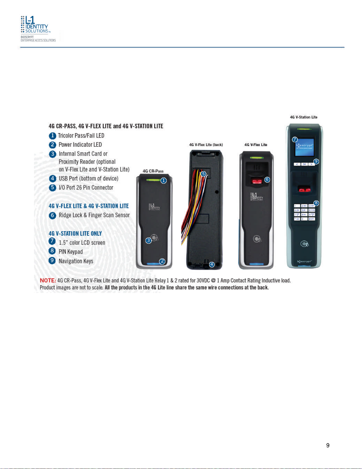
1.2.1 4G CR-PASS, 4G V-FLEX LITE & 4G V-STATION LITE
Figure 1-1 4G CR-Pass, 4G V-Flex Lite & 4G V-Station Lite
Introduction
Part # 430-4G-050-00-006
© 2011 - L-1 Identity Solutions Inc. All rights reserved
9
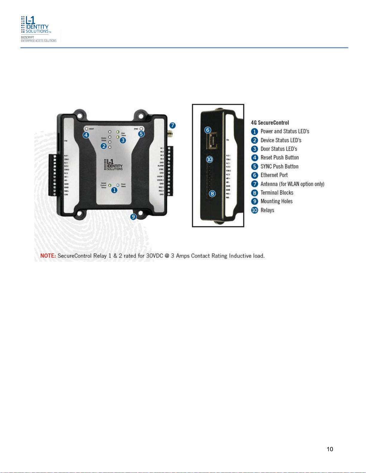
1.2.2 4G SECURE CONTROL
Figure 1-2 4G Secure Control
Introduction
Part # 430-4G-050-00-006
© 2011 - L-1 Identity Solutions Inc. All rights reserved
10
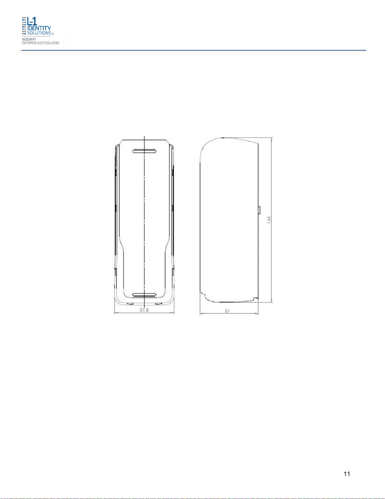
1.3 DEVICE DIMENSIONS
1.3.1 4G CR-PASS
Introduction
Figure 1-3 4G CR-Pass
Part # 430-4G-050-00-006
© 2011 - L-1 Identity Solutions Inc. All rights reserved
11
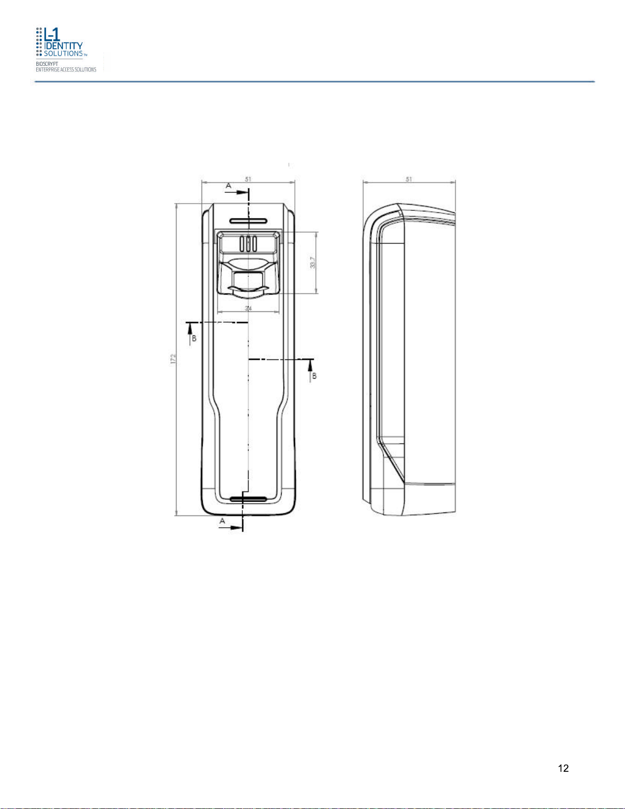
1.3.2 4G V-FLEX LITE
Introduction
Figure 1-4 4G V-Flex Lite
Part # 430-4G-050-00-006
© 2011 - L-1 Identity Solutions Inc. All rights reserved
12
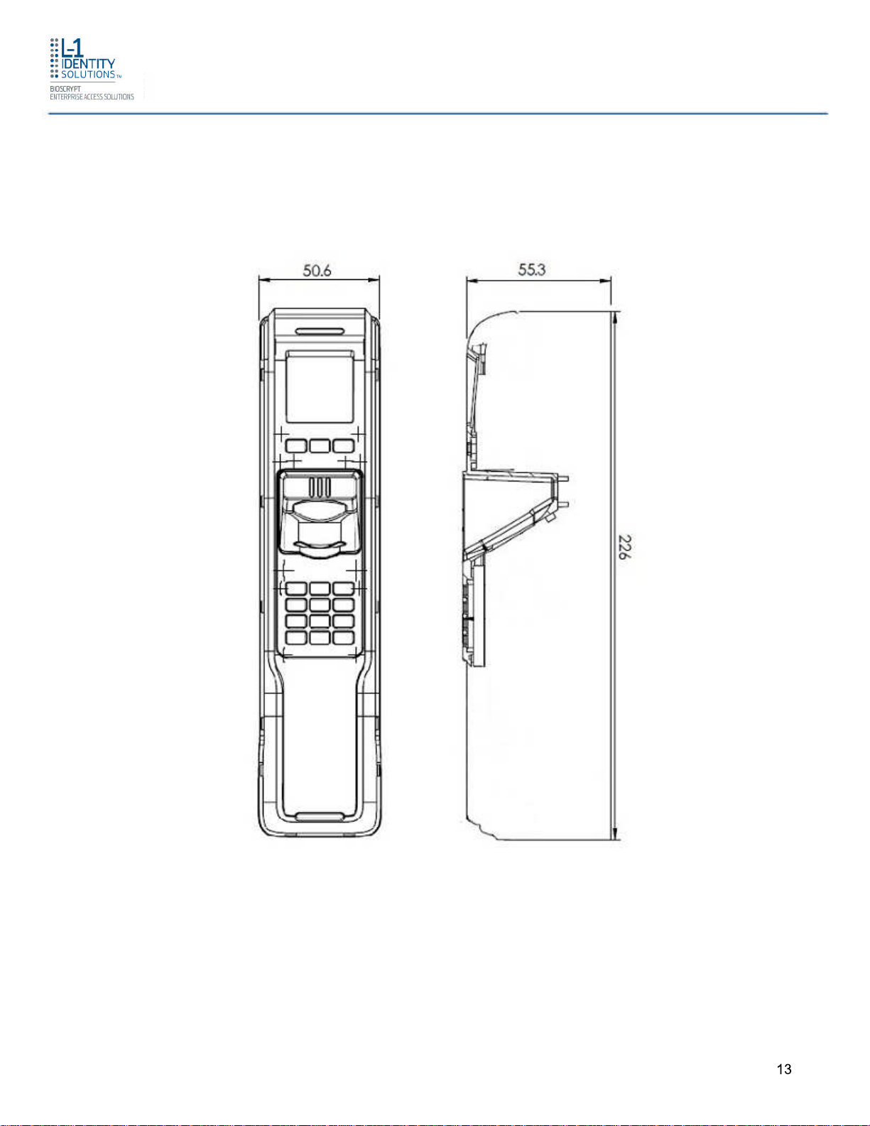
1.3.3 4G V-STATION LITE
Introduction
Figure 1-5 4G V-Station Lite
Part # 430-4G-050-00-006
© 2011 - L-1 Identity Solutions Inc. All rights reserved
13
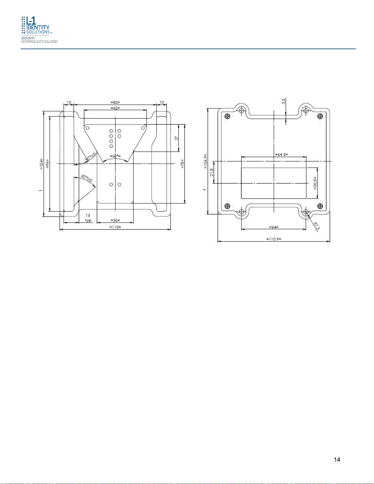
1.3.4 4G SECURE CONTROL
Introduction
Figure 1-6 4G Secure Control
Part # 430-4G-050-00-006
© 2011 - L-1 Identity Solutions Inc. All rights reserved
14
Introduction
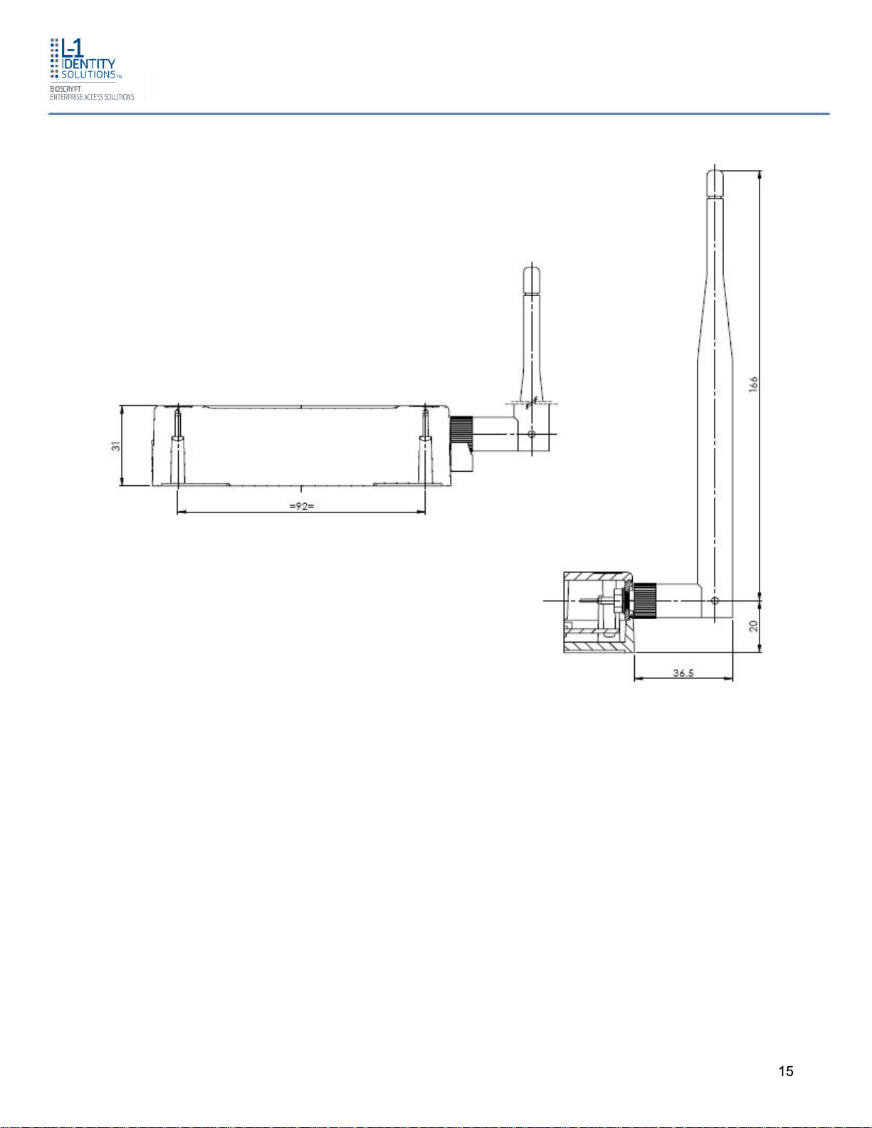
1.4 SAFETY PRECAUTIONS
Below are safety precautions that should be observed when operating or installing a device.
1.4.1 ELECTROSTATIC DISCHARGE
L-1 Identity Solutions recommends that Administrators inform Users of these points during
the enrollment process:
Always use the Ridge-Lock to position a finger *before* touching the
sensor.
Always stand on the ESD-dissipative floor covering (if installed).
Part # 430-4G-050-00-006
© 2011 - L-1 Identity Solutions Inc. All rights reserved
15

Do not touch other people or objects when touching the sensor.
Always maintain at least 12 inches of space around yourself when touching
the sensor.
Do not allow articles of clothing to touch the sensor.
L-1 Identity Solutions recommends that Installers always follow these points (in addition to
the points listed above):
When installing or working on a unit, always use a grounding wrist-strap
that is connected to a quality Earth ground.
Check the device's cabling for ground faults.
Ensure that the device's ground connection (located on the rear of the
device) is connected to a quality Earth Ground.
1.4.2 DEVICE HANDLING GUIDELINES
Introduction
Do not install the device in locations where the device would be exposed to
direct sunlight, high levels of relative humidity, particulate matter, or
flammable vapors.
Do not install the device near radiators or other heat sources.
Do not allow magnetic objects to come within close proximity to the device.
Strong magnetic fields might damage the device.
Do not let liquids spill on the device.
Do not attempt to alter the device for any reason. Modifications will void the
product warranty.
Do not attempt to disassemble the device in any way beyond what is
necessary for sensor field replacement.
Do not use the device for any purpose other than for what it was designed.
Do not plug any equipment into the USB port other than flash memory
devices.
Do not allow users to place or hang objects on the device, such as coffee
cups or purses.
Do clean the device regularly to remove dust, grime, and fingerprint residue.
Part # 430-4G-050-00-006
© 2011 - L-1 Identity Solutions Inc. All rights reserved
16

Planning the Installation
CHAPTER 2 - PLANNING THE INSTALLATION
CHAPTER OVERVIEW
This chapter details how to plan a successful installation, recommended steps, and explains
the hardware and software components of typical setup scenarios.
2.1 PLANNING THE INSTALLATION
Planning the installation is the single most important aspect of a successful installation. In
general, you need to consider the access controller, the door locks, the devices, and the
need for a network. By the time you are ready to install the system, all of the details
presented in the list below should be known. Take a moment to go through them now before
starting your installation.
During the planning phase, you should determine:
What type of authentication is required for your application?
How many doors need to be secured?
What type of device will be on each door? Doors already inside a secure
area might not need the same type or level of security.
If multiple 4G Lite devices require networking for template
distribution/management, then a dedicated PC is recommended to
administer the system, as well as an RS-485 to RS-232 converter, and
cabling for serial communications or cabling for Ethernet.
Verify that the chosen access controller supports the Wiegand formats
supported by 4G Lite devices.
Identify all wiring by the signal levels it is to carry. Use separate cables and
conduits for different signal groups to avoid cross talk. Plan to separate them
by these groups:
Power distribution: Wires carry power to devices, door strikes, etc.
Data communication: RS-485, USB, Wiegand, Ethernet, etc.
Signal: Door contact, request-to-exit push button, alarm input, etc.
When planning device placement, determine the distance limitation of each
signal type and use repeaters if necessary.
Part # 430-4G-050-00-006
© 2011 - L-1 Identity Solutions Inc. All rights reserved
17
Planning the Installation
If you have any unresolved issues with the items on this list, contact L-1 Identity Solutions
Technical Support for additional information before beginning any installation.
WARNING
4G Lite devices should be installed by only a qualified
technician. If you are not qualified to perform an
installation task, call L-1 Identity Solutions Technical
Support or contact a qualified installer.
2.1.1 RECOMENDED STEPS FOR A SUCCESSFUL INSTALLATION
Every installation is unique. Sometimes the issues are well defined and can be handled in a
standard fashion; sometimes the issues are very specific and may not be immediately
recognizable.
L-1 Identity Solutions recommends following these steps for a successful installation:
Plan the installation - Choose the type of hardware required, decide if a
network is required, and decide on the location and number of required
devices.
Unpack all items - Unpack all items and check against the packing list.
Install network hardware components - Install the cabling and
components needed to run the system.
Install software - Install the software needed to set up the devices.
Preconfigure device - Connect the device to the USB cable, supply power
to the device, and preconfigure the device.
Mount devices - Mount the devices in their final locations
Power distribution and device hook up - Connect the device wiring via
the back panel.
Power-up procedure - Check the power connections and start the system
safely. Enroll users into the system (for user enrollment procedures).
Chapters 3 through 7 in this document present more information on these steps.
Part # 430-4G-050-00-006
© 2011 - L-1 Identity Solutions Inc. All rights reserved
18

2.1.2 REQUIREMENTS
PC workstation with:
1 GHz Intel(r) Pentium(r) 4 processor or equivalent
1 GB RAM (2 GB recommended)
CD-ROM drive
One available COM port or USB port
Ethernet card
Display: 1024 x 768 high color (minimum)
Regulated DC Power supply
Door controller
Planning the Installation
TCP/IP network environment
RS-232 to RS-485 converter with power supply (for advanced administrative
features).
2.1.2.1 HARDWARE REQUIREMENTS
Deadbolt/door strike
Snubber diode required to protect regulated DC power supply from inductive
kickback(1N4007 diode or equivalent recommended)
Separate power supply for the deadbolt/door strike based on supplier's
recommendations.
External relay (if required)
Networking cable
2.1.2.2 COMPUTER REQUIREMENTS
2.1.2.2.1 SECUREADMIN LITE SERVER REQUIREMENTS
Hard disk space: 25 MB
Part # 430-4G-050-00-006
© 2011 - L-1 Identity Solutions Inc. All rights reserved
19

Planning the Installation
2.1.2.2.2 SECUREADMIN LITE CLIENT REQUIREMENTS
Hard disk space: 15 MB
2.1.2.2.3 MICROSOFT .NET FRAMEWORK 3.5 SP1 REQUIREMENTS
Hard disk space: Up to 500 MB might be required
2.1.2.2.4 SUPPORTED OPERATING SYSTEMS
SecureAdmin Lite Server and SecureAdmin Lite Client support these operating systems:
Windows Server 2003 R2
Windows Server 2008 R1
Windows XP Service Pack 2 or higher
Windows 7 32-bit and 64-bit
2.1.2.2.5 SQL SERVER 2008 EXPRESS EDITION
Hard disk space: 350 MB of available hard-disk space for the recommended
installation. Approximately 425 MB of additional available hard disk space
for SQL Server Books Online, SQL Server Mobile Books Online, and sample
databases.
During installation of SQL Server 2008, Windows Installer creates temporary
files on the system drive. Before running setup to install or upgrade SQL
Server, verify that at least 2.0 GB of disk space is available on the system
drive for these files
Actual Hard Disk Space Requirements: 280 MB for the recommended
installation.
2.1.2.3 NETWORK REQUIREMENTS
The 4G Lite devices function on 100 baseT networks.
2.1.2.4 SOFTWARE REQUIREMENTS
Both SecureAdmin Lite Server and SecureAdmin Lite Client require these software
applications as prerequisites:
.net Framework 3.5
Windows Installer 4.5
Part # 430-4G-050-00-006
© 2011 - L-1 Identity Solutions Inc. All rights reserved
20

Planning the Installation
SQL Server 2008 Express Edition
If these applications are not already installed, they will get installed during the setup process.
SecureAdmin Lite Server and SecureAdmin Lite Client also require System Administrator
access to install the application.
SecureAdmin Lite uses a self-signed certificate (x.509 certificate) with a file extension of .pfx
as default certificate. Certificate is installed on both SecureAdmin Lite Server and
SecureAdmin Lite Client components.
You have the option of installing your own certificate, which must be purchased from a
recognized authority in advance. In case of custom certificate, it should be first installed on
the PC. During SecureAdmin Lite Server & Client installation, you need to provide name and
other details of the custom certificate.
2.1.3 UNPACK EQUIPMENT
Unpack all items and check against the packing list.
2.1.3.1 PARTS LIST
2.1.3.1.1 4G CR-PASS, 4G V-FLEX LITE AND 4G V-STATION LITE
Qty 1 - 4G CR-Pass or 4G V-Flex Lite or 4G V-Station Lite Device
Qty 1 – Installation CD
Qty 1 – Stainless Steel Wall mounting plate
Qty 1 – 4G MicroUSB Device Cable
Qty 1 – 4G MicroUSB PC Cable
Qty 1 – Clamp-on Ferrite Core
Qty 1 – Machine Screw, Pin-in-Hex Security, Pan Head, SST, 6-32, 1/4”
Length
Qty 1 – Security Key, Pin-in-Hex, 2.5” Length
Qty 1 – Security Screw Retainer, Stainless Steel
Qty 2 – Self-Tapping Screw, Philip Pan Head, SST, #6, 1” Length
Qty 2 – Dry Wall Anchor, Nylon, #4-8, 1” Length
Part # 430-4G-050-00-006
© 2011 - L-1 Identity Solutions Inc. All rights reserved
21

Qty 2 – Machine Screw , Philip Pan Head, SST, 6-32, 3/4” Length
Qty 1 – “Bioscrypt” Logo Sticker
2.1.3.1.2 4G SECURECONTROL
Qty 1 - 4G SecureControl Device
Qty 1 –Terminal Block, 1x12po, 3.5mm, RA
Qty 1 –Terminal Block, 1x14po, 3.5mm, RA
Qty 4 – Dry Wall Anchor, Nylon, #4-8, 1” Length
Qty 4 – Self-Tapping Screw, Philip Pan Head, SST, #6, 1” Length
Planning the Installation
Qty 1 – “Bioscrypt” Logo Sticker
Qty 1 – Clamp-on Ferrite Core (WLAN only)
Qty 1 – Antenna, Omni Plug Connector (WLAN option)
2.1.3.1.3 DOCUMENTATION
4G CR Pass, 4G V-Flex Lite and 4G V-Station Lite:
1 Installation Guide (on Installation CD)
1 Operator's Manual (on Installation CD)
1 Quick Start Guide (on Installation CD and printed copy in package)
4G SecureControl:
1 Quick Start Guide (printed copy in package)
The documentation is provided in Adobe Acrobat format (PDF). The Adobe Acrobat Reader
application is available on the Installation CD or at: http://www.adobe.com
Part # 430-4G-050-00-006
© 2011 - L-1 Identity Solutions Inc. All rights reserved
22
Planning the Installation
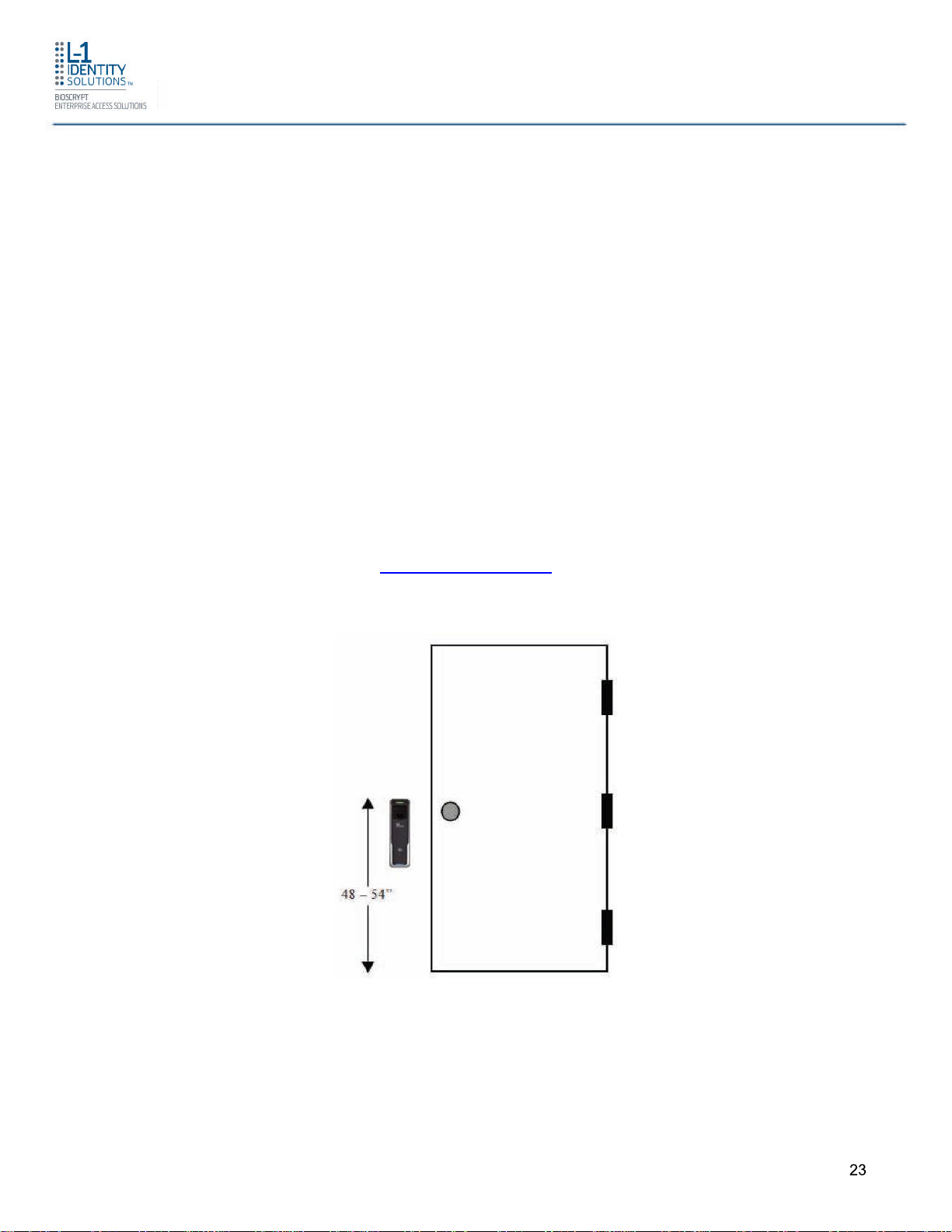
2.1.4 CHOOSING THE INSTALL LOCATION
2.1.4.1 4G CR Pass, 4G V-Flex Lite and 4G V-Station Lite
4G CR-Pass, 4G V-Flex Lite and 4G V-Station Lite devices are designed to mount on either a
single-gang electrical box or on any flat surface. Consult with local professionals regarding
any building and safety codes that might affect your installation. The correct mounting height
is shown below.
Factors to consider when determining the position of a device on the wall:
Proximity to other switch plates or fixtures (the device should ideally be
mounted in-line with other plates or fixtures)
Distance from the floor to the top of the device (L-1 Identity Solutions
recommends using a height between 48 and 54 inches).
The device should be mounted on the knob side of the door
Compliance with the Americans with Disabilities Act if in the United States.
Information about http://www.usdoj.gov.
Figure 2-1 Correct Mounting Height
2.1.4.2 4G SecureControl
4G SecureControl devices can be used in combination with any 4G Lite devices (up to
quantity of 4) for control of up to 2 physical doors. 4G SecureControl devices are also
designed to be placed on the secure side of the installation. 4G SecureControl must be
Part # 430-4G-050-00-006
© 2011 - L-1 Identity Solutions Inc. All rights reserved
23
Planning the Installation
placed in an area that is accessible only by Administrators and not by users during normal
operation. Some examples of installation options for 4G SecureControl include:
Fastened or securely placed in the ceiling
Wall-mounted
All of the above scenarios are valid given that the location is on the secure side of the
installation.
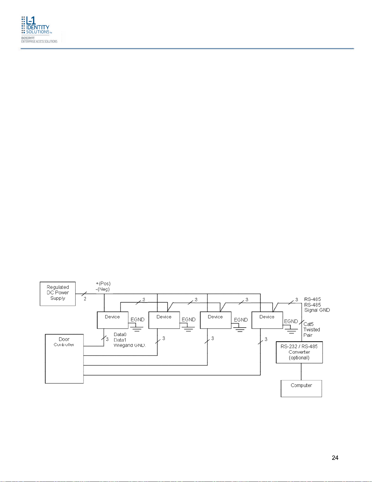
2.1.5 PLAN DEVICE NETWORK
The 4G Lite devices feature a built-in single-door relay that allows them to control a single
door lock. They can therefore function on their own or as part of a larger access control
system.
System component selection is specific to each installation, but a minimum system would
consist of a 4G Lite device mounted on or near an access point, an electric lock, and cabling.
A more complex system might consist of devices at multiple access points (each with an
electric door lock), a multi-point controller, networking, and a PC to run the access controller
and SecureAdmin Lite Server software.
See the diagram below for an example (non-Ethernet) system diagram.
Figure 2-2 Example RS-485 System Diagram
Installation of locks and access controllers should be completed according to their respective
manufacturers' specifications and in accordance with all local codes. Final connections to the
device are explained in more detail in Chapter 4.
Part # 430-4G-050-00-006
© 2011 - L-1 Identity Solutions Inc. All rights reserved
24
Planning the Installation
Spec
RS-485
100BaseT
To avoid externally generated transients, do not run any wires near utility AC power wiring,
lightning rod grounding wire, etc. Grounding equipment is required for ESD protection and
safety.
2.1.6 CHOOSE NETWORK TYPE
If your installation requires the use of network communications, then the choice of cable, the
cable run length, the network topology, and the termination of the network are important
aspects that must be considered. The 4G CR-Pass, 4G V-Flex Lite and 4G V-Station Lite
devices can be networked using RS-232, RS-485, or Ethernet protocols.
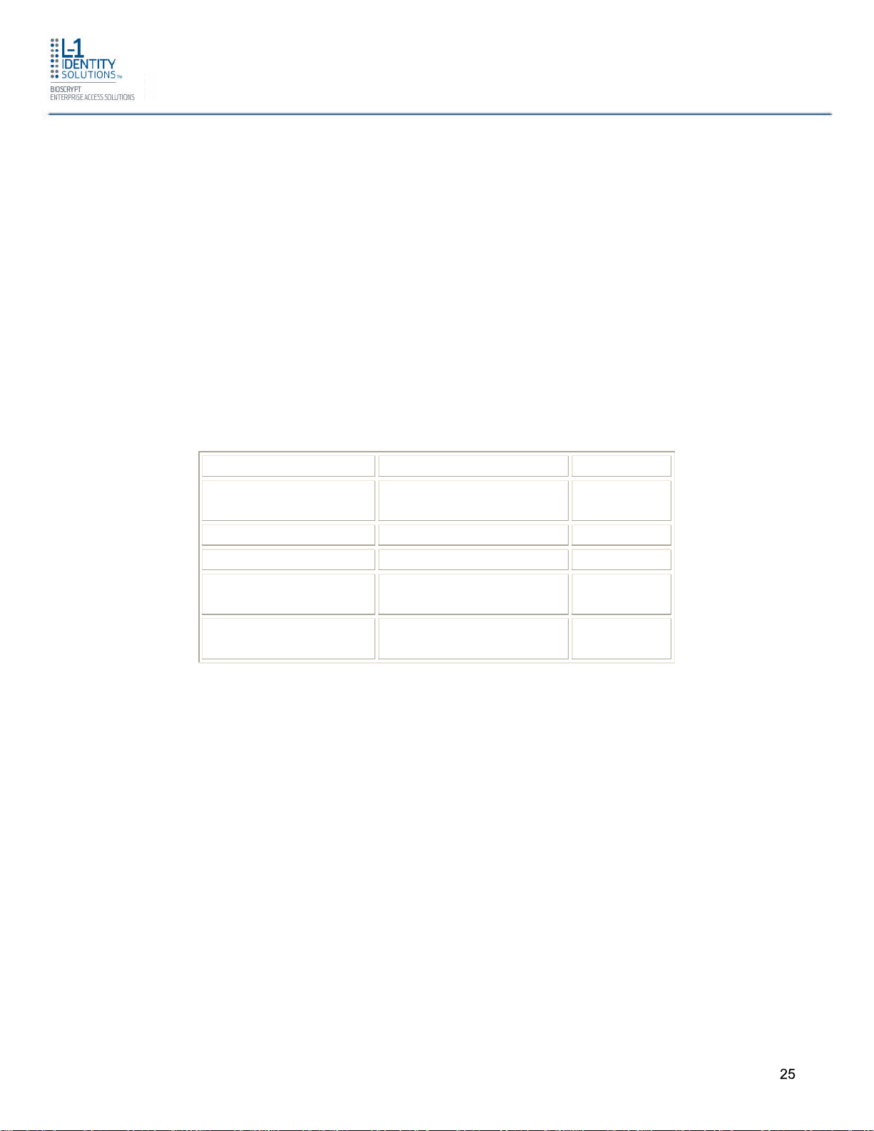
The table below outlines relevant parameters of the RS-485, RS-232, and 100 baseT
Ethernet communication protocols.
Table 2-1 Communications Network Comparison
Mode of Operation Differential DC
Multi
Coupled
DC Isolation No No
Maximum Distance 4000 feet 330 feet
Number of Devices
31 Unlimited
on one line
Maximum Data
Rate
57600 bps
(recommended)
Autonegotiated
2.1.6.1 RS-485
RS-485 has two distinct advantages over the more common RS-232. First, it allows you to
connect up to 31 4G Lite devices to a PC with an external RS-232 to RS-485 converter
(available from L-1 Identity Solutions). Second, the RS-485 specification allows for cable run
lengths up to 4000 feet (1200 meters) at modest baud rates.
An RS-485 network is required instead of RS-232 if:
Multiple devices must be connected together so that templates can be
distributed among the devices
The installation has only a single device, but it is over 150 feet (45 meters)
from the host PC.
Part # 430-4G-050-00-006
© 2011 - L-1 Identity Solutions Inc. All rights reserved
25
Planning the Installation
Specification
Recommendation
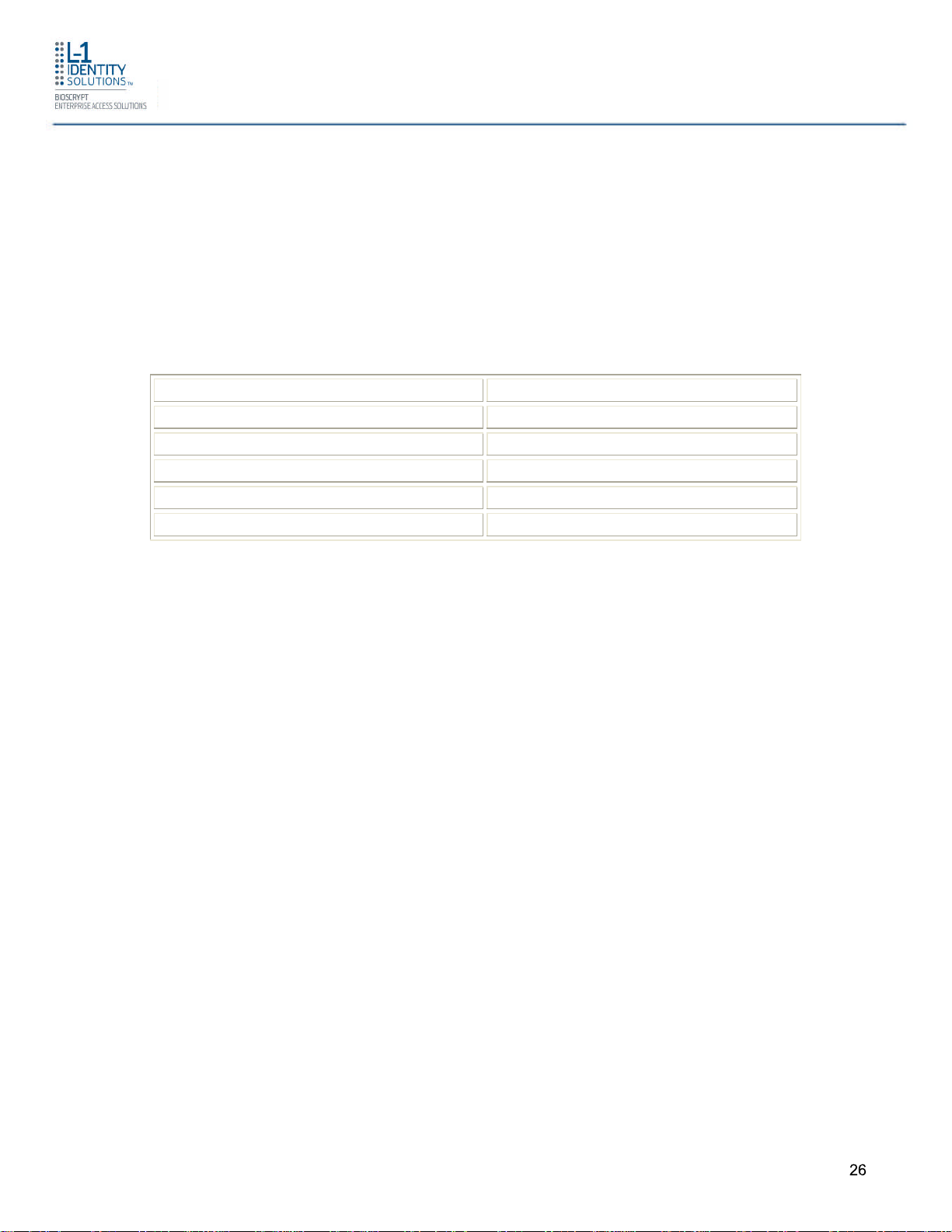
2.1.6.1.1 RS-485 CABLE SPECIFICATION
4G Lite devices provide a 2-wire, half-duplex RS-485 interface. The main cable run should be
low capacitance, twisted-pair cable, with approximately 120 ohm characteristic impedance.
Category-5 rated communications cable is used in RS-485 networks and its characteristics
are defined below. This is the recommended cabling for RS-485 communications. The cable
connection includes a differential line (A and B) and a GND connection.
Table 2-2 Category 5 Cable Characteristics
Capacitance (conductor to conductor) <20 pF/ft.
Characteristic Impedance 100 - 120 ohms
Nominal DC resistance <100 ohms/1000 ft.
Wire gauge 24 AWG stranded
Conductors/Shielding >2 pair (shielding is recommended)
2.1.6.1.2 RS-485 CABLE LENGTHS
As outlined in the RS-485 specification, the total length of the communication cable (adding
up all of the segments of the run) should not exceed 1200 meters (4000 feet). Although the
RS-485 specification calls for a maximum cable length of 1200 meters and provides a
maximum baud rate well above that of the 4G Lite device, a more conservative system
should be configured to no more than 1000 meters and run at a baud rate of 9600 bits per
second. After the network is configured and is running in a stable manner, the baud rate can
be increased if faster network communications are desired.
Drops (down-leads, stubs, T-connections, etc.) to equipment are not recommended, but if
required, should not exceed one foot) and should use the same cable recommended above.
On a long stub, a signal that travels down the wire reflects to the main line after hitting the
input impedance of the device at the end. This impedance is high compared with that of the
cable and the net effect is degradation of signal quality on the bus.
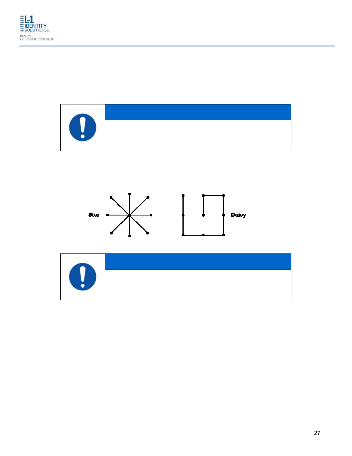
2.1.6.1.3 RS-485 NETWORK TOPOLOGY
Communication cables for RS-485 should be laid out in a daisy chain configuration (See
Figure 2-3). Long stubs or drop downs and the star configuration should be avoided because
they create discontinuities and degrade signal quality. The star configuration usually does not
provide a clean signalling environment even if the cable runs are all of equal length. The star
configuration also presents a termination problem, because terminating every endpoint
overloads the driver. Terminating only two endpoints solves the loading problem, but creates
Part # 430-4G-050-00-006
© 2011 - L-1 Identity Solutions Inc. All rights reserved
26
Planning the Installation
transmission line problems at the unterminated ends. A true daisy chain configuration avoids
these problems.
NOTICE
The device on the end of the network should be
terminated with a 120 ohm resistor.
Figure 2-3 Network Topologies Star and Daisy Chain Configurations
NOTICE
A Daisy configuration is recommended over a Star configuration.
2.1.6.2 ETHERNET
If your system is to be configured for use over Ethernet, the wiring will be slightly different.
Communication cables for Ethernet logically form a straight line bus but the more devices on
that bus, the less efficient the network becomes due to increased collisions, and the weaker
the signal will get over distance. Repeaters can be used to boost the signal strength;
however, a better solution is to place switches at intermediate positions along the bus. The
most common Ethernet topology in use today is the star configuration with a hub or switch in
the center.
Part # 430-4G-050-00-006
© 2011 - L-1 Identity Solutions Inc. All rights reserved
27

Planning the Installation
2.1.7 CHOOSE POWER SOURCE
4G CR-Pass, 4G V-Flex Lite, 4G V-Station Lite and 4G SecureControl devices can be
powered by several methods:
12V DC regulated (4G CR-Pass, 4G V-Flex Lite, 4G V-Station Lite and 4G
SecureControl)
Power Over Internet (PoE) through an inline PoE 802.3af power injector (4G
CR-Pass only)
Power sources should be:
Isolated from other equipment
Filtered
Protected by an Uninterruptible Power Supply (UPS) or battery backup
Protected by a voltage suppression device if transient electrical surges are
an issue in the location.
When planning a system, know the power requirement of each device. If multiple devices are
to share a common power supply, exercise care to avoid excessive voltage loss on the wires.
Voltage loss can lead to communication problems when devices are talking and/or listening
on different ground references.
Voltage loss is directly proportional to wire resistance and the current the wire carries. Always
place the device as close as possible to the power supply and always select a wire size
appropriate for the load. 4G Lite devices run on DC power between 12 V and 24 VDC.
Power requirements for all 4G CR-Pass, 4G V-Flex Lite, 4G V-Station Lite and 4G
SecureControl models are listed below:
Table 2-3 4G Lite Power Requirements
Power Requirement: 12 watts
Input Voltage Range: 12-24 VDC (-10%, +15%)
Peak Current (12 VDC) 500 mA
Peak Current (24 VDC) 250 mA
Most power supplies on the market today provide good input and output isolation. However,
power supplies which do not provide isolation (or have high leakage capacitance), coupled
Part # 430-4G-050-00-006
© 2011 - L-1 Identity Solutions Inc. All rights reserved
28

Planning the Installation
with accidental AC power line interchanges, present serious ground fault problems for
installers. With a ground fault, the signal reference between subsystems may be 115 VAC
apart. If these subsystems are interconnected, the large potential difference can cause
equipment damage or personal injury. L-1 Identity Solutions recommends using a dedicated
regulated DC power supply.
All factory-supplied power supply assemblies are either switching or regulated linear supplies
and are isolated for safety and to minimize ground loop problems.
Part # 430-4G-050-00-006
© 2011 - L-1 Identity Solutions Inc. All rights reserved
29

Install Software
CHAPTER 3 - INSTALL SOFTWARE
CHAPTER OVERVIEW
This chapter shows how to install, repair, modify, upgrade, and uninstall the SecureAdmin
Lite Server and Client software packages.
To install the SecureAdmin Lite software, the user must have Administrator rights. Any
software required to install SecureAdmin Lite is detected and installed automatically during
the setup process.
3.1 SECUREADMIN LITE SERVER
To install the SecureAdmin Lite Server software, follow these steps:
1. Insert the CD into the optical drive. If Autoplay is enabled, the installation process will start
automatically. A menu is displayed. If Autoplay is not enabled, start the installation
process manually by doubleclicking the Setup.exe file located in the "Bioscryptsetup"
folder on the root of the CD.
2. New Launch screen showing SecureAdmin Lite selection
Figure 3-1 Launch screen – SecureAdmin Lite
Part # 430-4G-050-00-006
© 2011 - L-1 Identity Solutions Inc. All rights reserved
30

3. Click 4G LiteReader – SecureAdmin Lite option.
Figure 3-2 Launch screen –Installation 32-bit or 64-bit
Install Software
4. Select appropriate installation (32-bit or 64-bit) according to your Operation System.
To determine if your computer is running a 32-bit or 64-bit OS version, please refer to the
link below:
http://windows.microsoft.com/en-CA/windows-vista/32-bit-and-64-bit-Windowsfrequently-asked-questions
.
Part # 430-4G-050-00-006
© 2011 - L-1 Identity Solutions Inc. All rights reserved
31

Figure 3-3 Install Menu
Install Software
5. Click Server Installation.
Part # 430-4G-050-00-006
© 2011 - L-1 Identity Solutions Inc. All rights reserved
32

Figure 3-4 SecureAdmin Lite Server Installation Wizard
Install Software
6. The Secure Admin Server Installation Wizard is displayed. Click Next to continue the
setup process.
Part # 430-4G-050-00-006
© 2011 - L-1 Identity Solutions Inc. All rights reserved
33

Figure 3-5 SecureAdmin Lite Server License Agreement
Install Software
7. The L-1 Identity Solutions License Agreement is displayed. Select the appropriate radio
button to agree with the terms and then click the Next button (You must accept the terms
of the licence agreement to continue the installation process).
Part # 430-4G-050-00-006
© 2011 - L-1 Identity Solutions Inc. All rights reserved
34

Figure 3-6 SecureAdmin Lite Server Choose Destination Location
Install Software
8. The Choose Destination Location screen is displayed. Accept the default installation
folder and click the Next button or click Browse to choose your own installation path. After
you specify a destination folder, the Database Selection screen is displayed.
Part # 430-4G-050-00-006
© 2011 - L-1 Identity Solutions Inc. All rights reserved
35

Figure 3-7 Database Selection
Install Software
9. Using the radio buttons, select the type of database application you intend to work with, or
select an existing database. Click the Next button.
If you selected the SQL Server 2008 Express Edition option, it will be installed locally if it is
not already installed.
Select SQL Server 2008 Express Edition option to install SQL Server 2008
on the local machine and Click Next.
Select Windows authentication or Database server authentication option
and enter a valid login ID and password values.
Enter the name of the database catalog or click Browse to select an
existing database catalog.
Click Next to continue.
Part # 430-4G-050-00-006
© 2011 - L-1 Identity Solutions Inc. All rights reserved
36

Figure 3-8 Connecting to SQL Server option
Install Software
If you selected Connect to Existing SQL Server option,
Select Connect to Existing SQL Server option and Click on Next.
You can select existing database instance of SQL Server 2005 or SQL
Server 2008 as required from the drop-down of Database server that you
are installing to.
Select the Database server authentication option and enter valid Login ID
and password values.
Accept the default database catalog or click Browse to select a different
database catalog.
Click Next to continue
Part # 430-4G-050-00-006
© 2011 - L-1 Identity Solutions Inc. All rights reserved
37

Install Software
3.1.1 REPAIRING AN INSTALLATION OF SECUREADMIN LITE SERVER
To repair an installation:
1. Login as Administrator and go to the Install.
2. Double-click the Setup.exe installer file to start the installer.
3. On the L1 Identity Solutions screen, select the Server Installation option.
4. On the SecureAdmin Lite Welcome screen, select the Repair option. Click Next to
continue.
5. On the Maintenance Complete screen, click the Finish button to complete the repair
installation process.
3.1.2 UNINSTALLING SECUREADMIN LITE SERVER
Uninstall SecureAdmin Lite Server by using either the Add/Remove Program function in
Windows or by using the Remove option from the installation file as outlined below.
You can also uninstall SecureAdmin Lite Server by using the Remove option within the
installation file. Follow the instructions above for repairing an Installation. Select the Remove
option instead of the Repair option, then follow the prompts.
3.1.3 UPGRADING AN INSTALLATION OF SECUREADMIN LITE SERVER
Installer of SecureAdmin Lite supports upgrading SecureAdmin Lite server from existing
(currently installed) version to a newer one.
1. When you run the setup of SecureAdmin Lite server, it checks to see if previous version of
SecureAdmin Lite server is already installed on the machine. If yes, it prompts to upgrade
SecureAdmin Lite server. Click Yes to continue with upgrade install.
Figure 3-9 Upgrade Confirmation
Part # 430-4G-050-00-006
© 2011 - L-1 Identity Solutions Inc. All rights reserved
38

Figure 3-10 SecureAdmin Lite Server Installation Complete
Install Software
3.2 SECUREADMIN LITE CLIENT
To install the SecureAdmin Lite client software, follow these steps:
1. Insert the CD into the optical drive. If Autoplay is enabled, the installation process will start
automatically. A menu is displayed. If Autoplay is not enabled, start the installation
process manually by doubleclicking the Setup.exe file located in the SecureAdmin Lite
folder on the CD.
Part # 430-4G-050-00-006
© 2011 - L-1 Identity Solutions Inc. All rights reserved
39

Figure 3-11 Menu
Install Software
2. Click Client Installation. The InstallShield Wizard is started and the target system is
examined. The Welcome screen is displayed.
Figure 3-12 InstallShield Wizard
Part # 430-4G-050-00-006
© 2011 - L-1 Identity Solutions Inc. All rights reserved
40

Figure 3-13 Welcome Screen
Install Software
3. Click the Next button to continue. The License Agreement screen is displayed.
Part # 430-4G-050-00-006
© 2011 - L-1 Identity Solutions Inc. All rights reserved
41

Figure 3-14 SecureAdmin Lite Client License Agreement
Install Software
4. The L-1 Identity Solutions License Agreement is displayed. Select the appropriate radio
button to agree with the terms and then click the Next button. The Choose Destination
Location screen is displayed.
Part # 430-4G-050-00-006
© 2011 - L-1 Identity Solutions Inc. All rights reserved
42

Figure 3-15 SecureAdmin Lite Client Choose Destination Location
Install Software
5. Accept the default installation folder and click the Next button or click Browse to choose
your own installation path. After you specify a destination folder, the Fingerprint
Selection Feedback selection screen is displayed.
Part # 430-4G-050-00-006
© 2011 - L-1 Identity Solutions Inc. All rights reserved
43

Figure 3-16 Fingerprint Placement Feedback Option Selection
Install Software
6. Select the appropriate radio button to either display or to not display fingerprint data. If
Display Fingerprint Image is selected, a fingerprint will be displayed while enrolling
templates. If the Display Fingerprint Placement Feedback option is selected, then
SecureAdmin Lite displays crosshair placement feedback instead of fingerprint images
while enrolling templates.
7. Click the Next button. The InstallShield Wizard completes the installation and displays a
Finished screen.
8. Select either or both of the optional Check Create Desktop Icon and Launch Secure
Admin Client check boxes.
Part # 430-4G-050-00-006
© 2011 - L-1 Identity Solutions Inc. All rights reserved
44

Figure 3-17 InstallShield Wizard Finished
Install Software
9. Click the Finish button.
3.2.1 MODIFYING AN INSTALLATION OF SECUREADMIN LITE CLIENT
To modify an installation:
1. Login as Administrator and go to the Secure Admin installer.
2. Double-click the Setup.exe installer file to start the installer.
3. On the L1 Identity Solutions screen, select the Client Installation option.
4. On the Secure Admin Welcome screen, select the Modify option. Click Next to continue.
5. Select the appropriate Fingerprint Placement Feedback option. If Display Fingerprint
Image is selected, fingerprints will be displayed while enrolling templates. If Display
Fingerprint Placement Feedback is selected, SecureAdmin Lite displays crosshair
feedback instead of fingerprint images while enrolling templates.
6. Click Next to continue.
7. On the Maintenance Complete screen, click the Finish button to complete the modified
installation.
Part # 430-4G-050-00-006
© 2011 - L-1 Identity Solutions Inc. All rights reserved
45

Install Software
3.2.2 REPAIRING AN INSTALLATION OF SECUREADMIN LITE CLIENT
To repair an installation:
8. Login as Administrator and go to the Secure Admin installer.
9. Double-click the Setup.exe installer file to start the installer.
10.On the L1 Identity Solutions screen, select the Client Installation option.
11.On the SecureAdmin Lite Welcome screen, select the Repair option. Click Next to
continue.
12.On the Maintenance Complete screen, click the Finish button to complete the repair
installation process.
3.2.3 UNINSTALLING SECUREADMIN LITE CLIENT
Uninstall SecureAdmin Lite Client by using either the Add/Remove Program function in
Windows or by using the Remove option from the installation file.
To uninstall SecureAdmin Lite client by using the Remove option within the installation file,
follow the instructions for repairing an installation. Select the Remove option instead of the
Repair option, then follow the prompts.
3.2.4 UPGRADING AN INSTALLATION OF SECUREADMIN LITE CLIENT
To upgrade a previous version of SecureAdmin Lite Client, first uninstall the older version
using Windows Add/Remove Programs or the SecureAdmin Lite installer, then re-install the
new version of SecureAdmin Lite Client.
Part # 430-4G-050-00-006
© 2011 - L-1 Identity Solutions Inc. All rights reserved
46

Install Hardware
CHAPTER 4 - INSTALL HARDWARE
CHAPTER OVERVIEW
This chapter explains how to install a 4G Lite device, how to mount a wall plate, how to attach
a device to a wall plate, and how to make the required electrical connections to the device.
4.1 WALL-MOUNTING SCHEMES
The 4G CR-Pass, 4G V-Flex Lite, 4G V-Station Lite devices are mounted, by use of a
mounting plate, either directly to a wall or to an electrical box recessed in the wall. The 4G
CR-Pass, 4G V-Flex Lite, 4G V-Station Lite devices can be flush mounted on a wall.
4G SecureControl devices are designed to be placed on the secure side of the installation
where it is only accessible by Administrators and not by users during normal operation (ie. in
the ceiling or wall-mounted), hence there is no mounting plate required.
4.2 INSTALLING A MOUNTING PLATE
The procedure for mounting a wall plate directly to a wall is as follows:
4.2.1 4G CR-PASS, 4G V-FLEX LITE AND 4G V-STATION LITE
1. Hold the mounting plate onto the wall in the desired location, trace the square hole that
will be cut out, and mark the mounting screw locations.
2. Cut out the square hole with a jigsaw or drywall saw. If the 4G Lite device is to be recessmounted, cut out a hole in the drywall to accommodate the rear extension on the device
housing.
3. Drill holes for the nylon wall anchors and install them.
4. Fish wires through the wall to the square hole.
5. Align the hole in the wall plate with the hole in the wall.
6. Fasten the mounting plate to the nylon wall anchors in the wall with the provided screws.
Part # 430-4G-050-00-006
© 2011 - L-1 Identity Solutions Inc. All rights reserved
47

Figure 4-1 4G CR-Pass Flush-mount Mounting Plate (in mm)
Install Hardware
Part # 430-4G-050-00-006
© 2011 - L-1 Identity Solutions Inc. All rights reserved
48

Figure 4-2 4G V-Flex Lite Flush-mount Mounting Plate (in mm)
Install Hardware
Part # 430-4G-050-00-006
© 2011 - L-1 Identity Solutions Inc. All rights reserved
49

Figure 4-3 4G V-Station Lite Flush-mount Mounting Plate (in mm)
Install Hardware
Part # 430-4G-050-00-006
© 2011 - L-1 Identity Solutions Inc. All rights reserved
50

Figure 4-4 4G SecureControl Mounting Hole Locations (in mm)
Install Hardware
4.3 INSTALLATION HARDWARE
4.3.1 4G CR-PASS, 4G V-FLEX LITE AND 4G V-STATION LITE Quantity
Qty 1 – Stainless Steel Wall mounting plate
Qty 2 - #6-32 3/4" Philips pan-head screw
Qty 2 - #6 1" Philips pan-head self-tapping screws
Qty 2 - #4-8 1" nylon wall anchors
The hardware listed above is provided to mount the mounting plate to the wall and the 4G
CR-Pass or 4G V-Flex Lite or 4G V-Station Lite device to the mounting plate.
Part # 430-4G-050-00-006
© 2011 - L-1 Identity Solutions Inc. All rights reserved
51

Install Hardware
4.4 ATTACH DEVICE TO MOUNTING PLATE
4.4.1 4G CR-PASS, 4G V-FLEX LITE AND 4G V-STATION LITE
Once all the electrical connections have been made to the device, it can be attached to the
mounting plate as follows:
For the 4G CR-Pass, 4G V-Flex Lite and 4G V-Station Lite, insert the hooked protrusions on
the rear of the device into the corresponding slots on the mounting plate. Hold the device
against the plate and gently press it in a downward direction to engage the hooks. Insert the
star-shaped screw at the bottom center of the mounting plate and tighten with the wrench
provided. Do not over-tighten.
4.5 CONNECT DEVICE TO POWER SOURCE
The 4G CR-Pass, 4G V-Flex Lite and 4G V-Station Lite can be powered by 12V DC power
source. The CR-Pass can be also powered through a Power over Ethernet (PoE) injector.
The two options for providing 12V power to 4G Lite devices are by using an external wall
plug-in adapter (Figure 4-13, or through external wiring and a mini plug (Figure 4-13).
Figure 4-5 Connections for an External Wall Adapter (4G Lite)
Part # 430-4G-050-00-006
© 2011 - L-1 Identity Solutions Inc. All rights reserved
52

Install Hardware
Figure 4-6 Connections for an External Power Source (4G Lite)
The 4G CR-Pass devices support Power over Ethernet (PoE), using their RJ-45 Ethernet
interface. When these devices are to be powered over Ethernet, an IEEE 802.3af compliant
Active Midspan Injector must be used. Such an injector is not supplied with L-1 Identity
Solutions products. An example of a suitable PoE injector is Model No. AT-61 01 G from
Allied Telesis Inc. (http://www.alliedtelesis.com).
Any such device should carry at least one of the certifications shown below and should be
FCC listed.
Figure 4-7 Certification Marks
Part # 430-4G-050-00-006
© 2011 - L-1 Identity Solutions Inc. All rights reserved
53

Figure 4-8 Power over Ethernet Connection
Install Hardware
Specifications for suitable PoE Injectors for 4G CR-Pass devices are as follows:
Input voltage: 90-264 VAC, 60 Hz
Input current: 0.4A @ 100 VAC
Output voltage: 48 VDC
Output current: 0.32A
Power: 15.36 W
For Power over Ethernet, RJ-45 pin numbers 4, 5 are considered VB1 (+) positive DC supply,
and pin numbers 7, 8 are VB2(-) DC return.
Detailed RJ-45 pin assignments for PoE are given in Table 4-1 PoE Pin Assignments, and
the physical location of the pins in Figure 4-14 the RJ-45 connector.
Part # 430-4G-050-00-006
© 2011 - L-1 Identity Solutions Inc. All rights reserved
54

Table 4-1 PoE Pin Assignments
48 V DC,
SOURCE LOAD REMARKS
Install Hardware
STANDARD
IEEE 802.3af
using spare
pairs
Source
Voltage
protected
Ethernet RJ-45 connector pin number
1 2 3 4 5 6 7 8
RX RX TX DC+ DC+ TX DC- DC- (embedded)
Figure 4-9 RJ45 Pin Location
4.6 CONNECT DEVICE TO NETWORK
Load
Voltage
DC Load
Connector
Industry
Standard
for
embedded
PoE
The 4G Lite devices support RS-485, Ethernet 10baseT and 100baseTX protocols.
4.6.1 ETHERNET NETWORK CONNECTIONS
Ethernet connections to the device are made through Ethernet wires available on the back of
the device. (RJ-45 Connector not included). Please see below for RJ-45 Connector
Configuration options.
Part # 430-4G-050-00-006
© 2011 - L-1 Identity Solutions Inc. All rights reserved
55

Figure 4-10 RJ45 Connector Configuration – 4G Lite
Install Hardware
4.6.2 RS-485 NETWORK CONNECTIONS
To connect a device to an RS-485 network, connect the appropriate wires to the provided
pigtail in accordance with the pin-out diagram.
Part # 430-4G-050-00-006
© 2011 - L-1 Identity Solutions Inc. All rights reserved
56

Figure 4-11 4G Lite Network - Pin-out Diagram
Install Hardware
When connecting the device to the network, the following procedures must be followed:
Use Category 5 cabling with a characteristic impedance of 120 ohms for RS-
485 networks. Category 5 cables with a characteristic impedance of 100
ohms can also be used, but with lower performance.
Cable manufacturers provide cables with multiple twisted pairs designed for
this type of communication (characteristic impedance is 120 ohm).
Unused pairs within the cable must be terminated with characteristic
impedance (100 or 120 ohm) on both ends.
AWG 24 should be considered as the minimum gauge.
Choose one twisted pair of conductors to use for RS-485 differential
connections, other conductors should be used for Signal Ground (RS-485
GND on Weidmuller connection).
The RS-232 to RS-485 converter must support Sense Data to be able to
switch from Send to Receive mode.
Check each device's cabling for ground faults before connecting to an RS-
485 network.
Each device should have pin 3 of the mini-connector connected to earth
ground.
Part # 430-4G-050-00-006
© 2011 - L-1 Identity Solutions Inc. All rights reserved
57

Install Hardware
After all devices are configured and connected to the RS-485 network, the baud rate can be
increased to the highest supported rate (some experimentation might be required).
4.7 SINGLE-DOOR CONTROLLER INSTALLATION
The 4G Lite devices incorporate an internal relay that enables them to operate a
deadbolt/door strike directly.
WARNING
The internal relay is limited to a maximum current of 1A. If the
deadbolt/ doorstrike to be controlled draws more than 1A, damage to
the device may occur. If the deadbolt/door strike load exceeds 1A,
an external relay must be used, as described below. Do not use the
same power supply to power a 4G Lite device and a door strike.
Assuming the current drawn by the deadbolt/door strike is less than 1A, the connections
between 4G Lite device, deadbolt/door strike, and power supply for the deadbolt/door strike
should be made. Note that a snubber diode (1N4007 or equivalent) must be connected
across the deadbolt/door strike to protect the DC power supply from inductive kickback.
CAUTION
The snubber diode and DC power supply for the deadbolt/door strike
are not supplied with the 4G Lite device. The power supply should
be specified in accordance with the voltage and current
requirements of the deadbolt/door strike, but it must be ensured that
the current to operate the dead bolt/door strike does not exceed 1A.
If the current required to operate the deadbolt/door strike exceeds 1A, an external relay must
be used in conjunction with the 4G Lite device. The external relay must be specified so that
its contacts are rated to carry the current required by the deadbolt/door strike, and that the
current required to operate its energizing coil is within the 1A capacity of the 4G Lite device's
internal relay.
Part # 430-4G-050-00-006
© 2011 - L-1 Identity Solutions Inc. All rights reserved
58

Install Hardware
Figure 4-12 Connections for Internal Relay Operation
The power supply for the external relay must be chosen to match the operating voltage and
current of the external relay coil, but its voltage must not exceed the 4G Lite device's internal
relay maximum voltage rating of 250 volts.
The external relay should be connected. Note that snubber diodes (1N2007 or equivalent)
should be connected across the external relay coil and the deadbolt/door strike.
Figure 4-13 Connections for External Relay Operation
Part # 430-4G-050-00-006
© 2011 - L-1 Identity Solutions Inc. All rights reserved
59

Install Hardware
4.8 AUX PORT
The Aux port is a USB 2.0 auto-negotiate connector located on the bottom of the device. To
access the Aux port, the Aux port door must first be removed. Use the provided pin-in-hex
security key to remove the #6-32 security screw retaining the plastic Aux port door. Gently
remove the plastic Aux port door to reveal the USB connector.
To attach a USB memory key or other "gadget" serial device by way of the Aux port, use the
USB Type A female to USB Micro A/B male adapter cable provided in the installation kit.
The Aux port is used to transfer files to and from the device. Audio (only on 4G V-Flex Lite
and 4G V-Station Lite devices), firmware, logs, and configuration files can be transferred
quickly and easily to a device without the need for a computer.
CAUTION
Current rating of the Aux port is not to exceed 100 mA Maximum.
Part # 430-4G-050-00-006
© 2011 - L-1 Identity Solutions Inc. All rights reserved
60
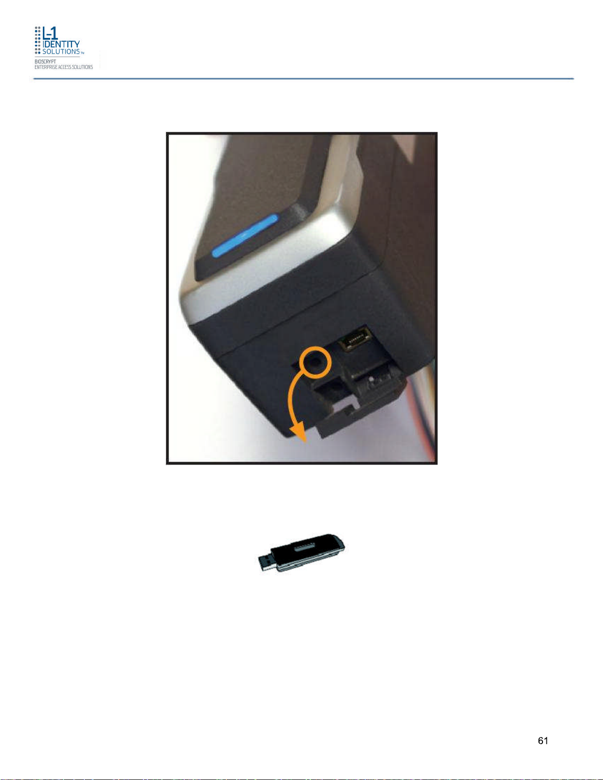
Figure 4-14 Location of Aux Port At the Bottom of the 4G Lite devices
Install Hardware
Figure 4-15 USB Memory Key
4.9 INSTALL FERRITE CORE
In order for the 4G Lite devices to comply with FCC Class B & CISPR 22 Class B regulations,
the installer and/or end user is required to use the supplied Ferrite Material with 3 turns on
the Ethernet cables exiting the rear of all 4G CR-Pass, 4G V-Flex Lite and 4G V-Station Lite
models.
Part # 430-4G-050-00-006
© 2011 - L-1 Identity Solutions Inc. All rights reserved
61

Install Hardware
In addition, compliance with the above regulations requires the installer and/or end user to
use the supplied Ferrite Material with 3 turns on the I/O lines for the 14-pin terminal block
cables of the 4G SecureControl device with WLAN option only.
Ethernet Ferrite P/N: STEWARD 28A2432-0A2
I/O Lines P/N: STEWARD 28A2432-0A2
Install the ferrite cores as close to the device as possible.
Part # 430-4G-050-00-006
© 2011 - L-1 Identity Solutions Inc. All rights reserved
62

System Start-Up Procedures
CHAPTER 5 - SYSTEM START-UP PROCEDURES
CHAPTER OVERVIEW
This chapter explains the various start-up procedures and checks that should be performed
before applying power to a device.
5.1 SYSTEM START-UP PROCEDURES
To avoid the need for difficult troubleshooting, system start-up must follow this step-by-step
procedure. Never wire up a system and apply power to it all at once.
SYSTEM START-UP OVERVIEW
Bioscrypt recommends always following these system start-up steps:
1. Do not apply power to any device.
2. Check all wiring and device configurations.
3. Disconnect all devices from the communication line.
4. Check the supply voltage for correct voltage.
5. Power up the PC running SecureAdmin Lite.
6. Power up the RS-232 to RS-485 converter (if installed).
7. Configure SecureAdmin Lite.
8. Perform a ground fault check for the converter (if installed).
9. Connect the PC and converter (if installed) to the communication line.
10.Verify that the device powers up correctly, but do not connect it to the communication line.
The power LED should be illuminated. Check the power lines with a voltmeter.
11.Perform a ground fault check for the device (if using RS-485, see below).
12.Connect the device to the communication line.
13.Verify that the device communicates with SecureAdmin Lite.
14.If there are more devices, repeat Steps 10 through 13 for each device.
Part # 430-4G-050-006
© 2011 - L-1 Identity Solutions Inc. All rights reserved
63

System Start-Up Procedures
5.1.1 DEVICE CONFIGURATION CHECK
Devices must be configured correctly before they can communicate. Common problems
include incorrect Host Port Protocol settings, mismatched Baud rates, and incorrect device
Net-work IDs. Each device sharing a communication line must have a unique device Network
ID.
5.1.2 RS-232 TO RS-485 CONVERTER GROUND FAULT CHECK
Before a device can be connected to an RS-485 subsystem, it must be checked for ground
faults. An uncorrected ground fault can damage all devices connected to the RS-485
communication line.
To check for a ground fault on the RS-232 to RS-485 converter:
1. Apply power to the RS-232 to RS-485 converter.
2. Connect the signal ground of the RS-485 line through a 10k ohm current-limiting resistor
to the signal ground of the RS-232 to RS-485 converter. There should be no more than 1
volt across the resistor.
5.1.3 DEVICE GROUND FAULT CHECK
To check for a ground fault on a new 4G Lite device:
1. Apply power to all devices already successfully connected to the RS-485 line.
2. Power up the new device but do not connect it to the RS-485 line.
3. Connect the signal ground of the RS-485 line through a 10k ohm current-limiting resistor
to the signal ground of the 4G Lite device.
4. There should be no more than 1 volt across the resistor. If there is, find and clear the fault.
5. Repeat Steps 1 through 3 with each of the RS-485 signal lines (+ and -).
6. Connect the new device to the RS-485 line only if no ground fault is found.
Part # 430-4G-050-006
© 2011 - L-1 Identity Solutions Inc. All rights reserved
64

Configure Device
CHAPTER 6 - CONFIGURE DEVICE
OVERVIEW
This chapter explains how to configure devices. All 4G Lite devices must be configured
before use. This includes setting various communication parameters.
6.1 REGISTER DEVICE
After a device is physically installed, it must be registered. This can be done several ways -when a device is connected by means of a network (this is the recommended method), or
when the device is connected directly to the host computer upon which SecureAdmin Lite is
running.
6.1.1 TO REGISTER A NETWORKED DEVICE
1. Launch SecureAdmin Lite.
2. Click the Network tab. Three buttons are displayed.
Part # 430-4G-050-00-006
© 2011 - L-1 Identity Solutions Inc. All rights reserved
65

Figure 6-1 Network Sidebar Tab
Configure Device
3. Click the Register via Server button. A Register via Server dialog box is displayed.
Part # 430-4G-050-00-006
© 2011 - L-1 Identity Solutions Inc. All rights reserved
66

Figure 6-2 Register via Server Dialog Box
Configure Device
4. Select the Search Automatically check box (UDP protocol must be enabled on the
network.
5. Click the Scan button. SecureAdmin Lite scans the network for connected devices and
lists the results. Devices with "plus" signs in their icon are available to add.
Part # 430-4G-050-00-006
© 2011 - L-1 Identity Solutions Inc. All rights reserved
67

Figure 6-3 Server Communication Parameter
Configure Device
6. In the list, click the icon of the device you want to register. The server communication
parameter dialog box is displayed. A Register Device dialog box is displayed. Select the
communication parameter (if connecting via RS-232 or RS-485), enter the appropriate
Port, Baud Rate, Device ID, and select the communication protocol from the drop-down. If
connecting via enter the network IP address of the device (select the DHCP check box if
dynamic IP addressing is used).
Figure 6-4 Register Device Dialog Box
7. Enter a Device Name.
Part # 430-4G-050-00-006
© 2011 - L-1 Identity Solutions Inc. All rights reserved
68

8. Select a Group.
9. Click Register. A Device Summary is displayed.
Figure 6-5 Device Summary Dialog Box
Configure Device
10.Click OK.
11.Click Close. The device is registered.
Part # 430-4G-050-00-006
© 2011 - L-1 Identity Solutions Inc. All rights reserved
69

Configure Device
6.1.2 TO REGISTER A DEVICE VIA A CLIENT
1. Launch SecureAdmin Lite.
2. Double-click the Network tab. Three buttons are displayed.
3. Click the Register via client button. The Step 1 Find Device dialog box is displayed.
Figure 6-6 Step 1 Find Device Dialog Box
4. Select either Serial Port - this machine or Ethernet radio button.
5. Enter the appropriate connection details.
If you are connecting via USB/RS-232:
Enter the appropriate Port Number (to determine the correct port number, look in the
Windows Device Manager for a "Gadget Serial" entry under the "Ports (COM & LPT)"
heading), Baud Rate, and Device ID.
If you are connecting via RS-485:
Enter the appropriate Port Number (to determine the correct port number, look in the
Windows Device Manager for your RS-485 entry under the "Ports (COM & LPT)" heading),
Baud Rate, and Device ID.
If you are connecting via Ethernet:
Enter the network IP Address of the device you want to connect to.
Part # 430-4G-050-00-006
© 2011 - L-1 Identity Solutions Inc. All rights reserved
70

NOTICE
The first time a 4G V-Flex Lite or 4G CR-Pass device is connected
to the computer via the USB interface, the Windows Found New
Hardware Wizard might start. As all required device drivers are
installed when SecureAdmin Lite is installed, simply follow the
prompts, accepting the default choices when possible, to install the
device.
6. Click Next. The Step 2 Device Information dialog box is displayed.
Figure 6-7 Step 2 Device Information Dialog Box
Configure Device
7. Click Next. The Step 3 Server Communication Parameter dialog box is displayed.
Part # 430-4G-050-00-006
© 2011 - L-1 Identity Solutions Inc. All rights reserved
71

Figure 6-8 Step 3 Server Communication Parameter Dialog Box
Configure Device
8. Select the radio button that corresponds how the server will connect to the device, either
by Serial Port or by Ethernet.
9. If connecting via RS-485, enter the appropriate Port, Baud Rate, and Device ID and
select the communication protocol from the dropdown. If connecting via Ethernet, enter
the network IP Address of the device (select the DHCP check box if dynamic IP
addressing is used).
10.Click Next. The Step 4 Register Device dialog box is displayed.
Figure 6-9 Step 4 Register Device Dialog Box
Part # 430-4G-050-00-006
© 2011 - L-1 Identity Solutions Inc. All rights reserved
72

11.Enter a Device Name.
12.Select the Group the device will belong to from the drop-down menu.
13.Click Register. The Device Summary dialog box is displayed.
Figure 6-10 Device Summary Dialog Box
Configure Device
Part # 430-4G-050-00-006
© 2011 - L-1 Identity Solutions Inc. All rights reserved
73

Maintenance and Cleaning
CHAPTER 7 - MAINTENANCE AND CLEANING
CHAPTER OVERVIEW
This chapter explains how to clean the 4G V-Flex Lite and 4G V-Station Lite device sensor.
The 4G V-Flex Lite and 4G V-Station Lite devices require very little in the way of daily
maintenance except for occasional cleaning and disinfecting.
7.1 CLEANING FINGER PRINT DEVICES
Sensors become soiled with residue, oils, or other contaminants due to contact with fingers
and exposure to the elements. The sensor surface should be cleaned periodically for
performance, aesthetic, and hygienic reasons. Care must be taken when cleaning the sensor
to prevent damaging the sensor surface or surrounding components.
To clean the fingerprint sensor in a 4G V-Flex Lite and 4G V-Station Lite devices:
1. Remove the electrical power from the device.
2. Moisten (do not saturate) a clean cotton swab or a lint-free cloth with rubbing (Isopropyl)
alcohol.
CAUTION
Do not use chlorine based cleaners, such as bleach, or chlorine
based bathroom or mildew cleaners. Chlorine-based cleaners will
not adversely affect the fingerprint sensor, but they could damage
the electronic circuitry sur-rounding the fingerprint sensor.
Do not use solvents such as acetone, methyl ethyl ketone, lacquer
thinner, etc. Solvents will not adversely affect the sensor, but they
are likely to damage the reader housing or other peripheral
components.
WARNING
Never use products such as abrasive cleaning powders, steel wool,
scouring pads, or fine sandpaper to clean the sensor surface. These
types of cleaning products will damage the sensor surface.
Part # 430-4G-050-00-006
© 2011 - L-1 Identity Solutions Inc. All rights reserved
74

Maintenance and Cleaning
3. Rub the sensor surface with the moistened cotton swab or lint-free cloth. Do not allow the
cleaning product to drip onto any electronic components near the sensor.
4. Rub the sensor with a clean dry cotton swab or lint-free cloth to remove any traces of
cleaning product.
5. Reconnect power to the device.
NOTICE
Disposable ESD-safe wipes, such as ACL Staticide wipes, can be
used to disinfect the sensor and buttons on a daily (or even more
frequent) basis. Be aware that some wipes might not offer the same
cleaning power as the products mentioned above and thus should
not be relied upon to thoroughly remove all residue. Use of wipes
does, however, helps keep sensor and button surfaces hygienic and
makes an excellent complement to periodic cleaning.
CAUTION
Risk of explosion if battery is replaced by an incorrect type.
Dispose of used batteries according to the instruction.
Part # 430-4G-050-00-006
© 2011 - L-1 Identity Solutions Inc. All rights reserved
75

Troubleshooting
CHAPTER 8 - TROUBLESHOOTING
CHAPTER OVERVIEW
This chapter informs about error messages that might be experienced during the installation
process.
8.1 INSTALLATION ERROR MESSAGES
These error messages might occur during the SecureAdmin Lite installation process.
8.1.1 ERROR 1406 - INSUFFICIENT PRIVILEGES
Figure 8-1 Error 1406
This error can occur during SecureAdmin Lite Client installation at the last step (right before
"Finish"). If it occurs, it means that the user does not have sufficient rights to install software
on the computer.
Part # 430-4G-050-00-006
© 2011 - L-1 Identity Solutions Inc. All rights reserved
76

Troubleshooting
Log off and log on either as a Administrator or another user that has sufficient privileges to
install software and perform the setup process again.
8.1.2 ERROR 27552 - ERROR CREATING DATABASE
Figure 8-2 Error 27552
This error can occur during SecureAdmin Lite Server installation process. If it occurs, it
means that the user does not have sufficient privileges to access a specific SQL database.
Contact your IT department to ensure that your privileges are correct for the specified
database.
Part # 430-4G-050-00-006
© 2011 - L-1 Identity Solutions Inc. All rights reserved
77

8.1.3 INVALID PASSWORD
Troubleshooting
Figure 8-3 Invalid Password
This error can occur during SecureAdmin Lite Server installation process on the User
configuration screen (after the database configuration screen).
If it occurs, it means that the password provided is not strong enough. Click OK, and re-enter
a password that is considered more secure. The password should be between 8 and 30
characters long and contain at least one capital letter, one number, and one nonalphanumeric character.
Part # 430-4G-050-00-006
© 2011 - L-1 Identity Solutions Inc. All rights reserved
78

8.1.4 ERROR 27502 - USER NOT ASSOCIATED WITH TRUSTED SQL SERVER
Figure 8-4 Error 27502 - User Not Associated
Troubleshooting
This error can occur during the SecureAdmin Lite Server installation process. If it occurs, it
means that the InstallShield Wizard could not access the specified SQL database.
Check your user name and password or contact your IT department to ensure that your user
name is associated with the specified SQL database.
Part # 430-4G-050-00-006
© 2011 - L-1 Identity Solutions Inc. All rights reserved
79

8.1.5 ERROR 27502 - SQL SERVER DOES NOT EXIST
Figure 8-5 Error 27502 - Server Does Not Exist
Troubleshooting
This error can occur during the SecureAdmin Lite Server installation process (at the time of
database configuration, after the database selection screen). If it occurs, it means that the
InstallShield Wizard could not connect to the specified SQL database because it does not
exist or because the user is not authorized to access that database
Check your user name and password or contact your IT department to ensure that your user
name is authorized to access the specified SQL database.
Part # 430-4G-050-00-006
© 2011 - L-1 Identity Solutions Inc. All rights reserved
80

Troubleshooting
8.1.6 INSUFFICIENT SYSTEM MEMORY
Figure 8-6 Insufficient System Memory
This error can occur during the SecureAdmin Lite Server installation process at the first
screen after selecting server installation from the options screen.
If it occurs, it means that the computer you are trying to install SecureAdmin Lite Server on
does not have sufficient system memory. Install more memory or install on a different
machine.
8.1.7 OUT OF DISK SPACE
Figure 8-7 Out of Disk Space
Part # 430-4G-050-00-006
© 2011 - L-1 Identity Solutions Inc. All rights reserved
81

Troubleshooting
This error can occur during the SecureAdmin Lite Client installation process when
SecureAdmin Lite starts to configure components, after the fingerprint feedback options
selection.
Part # 430-4G-050-00-006
© 2011 - L-1 Identity Solutions Inc. All rights reserved
82

CHAPTER 9 - NOTICES
CHAPTER OVERVIEW
The 4G lines of products have been tested for compliance with all applicable international
standards. The resulting approvals are listed below, and are additionally printed on the
labelling located on the rear panel of the product.
4G CR-Pass FCC, IC, CE
4G V-Flex Lite FCC, IC, CE
4G V-Station Lite FCC, IC, CE
4G Secure Control FCC, IC, CE
Notices
9.1 FCC and IC Information to Users
This device complies with part 15 of the FCC Rules. Operation is subject to the following two
conditions: (1) This device may not cause harmful interference, and (2) this device must
accept any interference received, including interference that may cause undesired operation.
NOTICE
This equipment has been tested and found to comply with
the limits for a Class B digital device, pursuant to part 15 of the FCC
Rules. These limits are designed to provide reasonable protection
against harmful interference in a residential installation. This
equipment generates uses and can radiate radio frequency energy
and, if not installed and used in accordance with the instructions,
may cause harmful interference to radio communications. However,
there is no guarantee that interference will not occur in a particular
installation. If this equipment does cause harmful interference to
radio or television reception, which can be determined by turning the
equipment off and on, the user is encouraged to try to correct the
interference by one or more of the following measures:
- Reorient or relocate the receiving antenna.
- Increase the separation between the equipment and receiver.
- Connect the equipment into an outlet on a circuit different from that
to which the receiver is connected.
- Consult the dealer or an experienced radio/TV technician for help.
Part # 430-4G-050-00-006
© 2011 - L-1 Identity Solutions Inc. All rights reserved
83

énoncé de la FCC (états-Unis seulement)
Cet équipement a été testé et jugé conforme aux limites de Classe B pour
un appareil numérique, en vertu de l’article 15 de la réglementation de la
FCC. Ces limites ont été instaurées pour fournir une protection
raisonnable contre toute interférence nuisible dans une installation
résidentielle. Cet équipement génère, utilise et peut émettre de l’énergie
radiofréquence. S’il n’est pas installé et utilisé conformément aux
instructions, il peut provoquer des interférences sur les communications
radio. Cependant, il n’est pas garanti que des interférences ne se
produiront pas dans certaines installations. Si cet équipement cause des
interférences à la réception radio ou télévisée (ce qui peut être vérifi é en
éteignant l’appareil puis en le remettant sous tension), l’utilisateur peut
tenter de les résoudre en suivant une ou plusieurs des mesures ci-après :
Réorienter ou déplacer l’antenne réceptrice. Augmenter l’espace entre
l’appareil et le récepteur. Brancher l’appareil à une prise de courant
différente de celle sur laquelle le récepteur est branché.
Pour obtenir de l’aide, contacter le vendeur ou un technicien
radio/télévision expérimenté.
REMARQUE : Toute modifi cation non autorisée expressément par le
fabricant responsable de la conformité peut
Annuler le droit de l’utilisateur à faire fonctionner le produit.
Notices
This Class B digital apparatus complies with Canadian ICES-003.
This device complies with Industry Canada license-exempt RSS standard(s). Operation is
subject to the following two conditions: (1) this device may not cause interference, and (2)
this device must accept any interference, including interference that may cause undesired
operation of the device.
Le présent appareil est conforme aux CNR d'Industrie Canada applicables aux appareils
radio exempts de licence. L'exploitation est autorisée aux deux conditions suivantes : (1)
l'appareil ne doit pas produire de brouillage, et (2) l'utilisateur de l'appareil doit accepter tout
brouillage radioélectrique subi, même si le brouillage est susceptible d'en compromettre le
fonctionnement.
Applicable only to V4GSCW which has WLAN:
This product complies with FCC radiation exposure limits set forth for an uncontrolled
environment. To comply with FCC RF exposure requirements, it must be installed and
operated in accordance with provided instructions. The unit requires minimum 20cm (8inch)
spacing between the unit and all persons’ body (excluding hands and feet) during wireless
modes of operation. This equipment complies with IC radiation exposure limits set forth for an
uncontrolled environment.
Part # 430-4G-050-00-006
© 2011 - L-1 Identity Solutions Inc. All rights reserved
84

Cet équipement est conforme aux limites d'exposition aux rayonnements définies par IC pour
un environnement non contrôlé. Cet équipement doit être installé et utilisé avec un minimum
de 20 cm.
Under Industry Canada regulations, this radio transmitter may only operate using an antenna
of a type and maximum (or lesser) gain approved for the transmitter by Industry Canada.
To reduce potential radio interference to other users, the antenna type and its gain should be
so chosen that the equivalent isotropically radiated power (e.i.r.p.) is not more than that
necessary for successful communication.
Conformément à la réglementation d'Industrie Canada, le présent émetteur radio peut
fonctionner avec une antenne d'un type et d'un gain maximal (ou inférieur) approuvé pour
l'émetteur par Industrie Canada. Dans le but de réduire les risques de brouillage
radioélectrique à l'intention des autres utilisateurs, il faut choisir le type d'antenne et son gain
de sorte que la puissance isotrope rayonnée équivalente (p.i.r.e.) ne dépasse pas l'intensité
nécessaire à l'établissement d'une communication satisfaisante.
This radio transmitter 4GSCW has been approved by Industry Canada to operate with the
antenna types listed below with the maximum permissible gain and required antenna
impedance for each antenna type indicated. Antenna types not included in this list, having a
gain greater than the maximum gain indicated for that type, are strictly prohibited for use with
this device.
Notices
Le présent émetteur radio 4GSCW a été approuvé par Industrie Canada pour fonctionner
avec les types d'antenne énumérés ci-dessous et ayant un gain admissible maximal et
l'impédance requise pour chaque type d'antenne. Les types d'antenne non inclus dans cette
liste, ou dont le gain est supérieur au gain maximal indiqué, sont strictement interdits pour
l'exploitation de l'émetteur.
Antenna: S151AH-2450S, NEARSON INC.
9.2 CE Information to Users
All 4G Lite devices and 4G Secure Control have the CE mark, for compliance with
CISPR22/EN55022 requirements. For European Union (EU) countries, 4G Lite devices and
4G Secure Control are compliant with CE under the R&TTE Directive, related to the radio
transceivers that are part of their design.
9.3 Warning to Users
CAUTION
Part # 430-4G-050-00-006
© 2011 - L-1 Identity Solutions Inc. All rights reserved
85

Changes or modifications not expressly approved by Bioscrypt
Inc. (a division of L-1 Identity Solutions Inc.) could void the user's
authority to operate the equipment.
Notices
Part # 430-4G-050-00-006
© 2011 - L-1 Identity Solutions Inc. All rights reserved
86

Glossary and Acronyms
GLOSSARY
1:1 Mode - In 1:1 mode, a user enters his or her User ID first. Then the user is requested to
place a fin-ger or enter a PIN. In 1:1 Mode, the user’s scanned fingerprint is matched against
the one specified by the user ID.
1:N Mode - In 1:N mode, a user places his or her finger on the device without entering an ID.
The device compares the user’s scanned fingerprint with the many enrolled fingerprints in its
internal database. Admin/Administrator - A user who is authorized to manage the settings
and user information of a fin-gerprint reader. Administrators can enroll or delete users and
change device settings.
Core - a term used to describe an area of the finger-scan characterized by ridgelines with the
tightest curvature and most unique content. Although the entire finger-scan has significant
data, the "core" is the most data-intensive area and thus is extremely important to the
algorithm. Normally, the core is located in the middle of the fingerprint.
Duress Mode - A mode that offers users a way of indicating a duress situation (such as
being forced to open a door). The user verifies with a specially designated finger resulting in
an inverted Wiegand output that is detectable on certain Access Control Panels.
Enrollment - The process of extracting features of a fingerprint image obtained from a
fingerprint sensor and saving them into the internal memory of a device. The fingerprint data
is called a fingerprint tem-plate.
Finger Placement Feedback (FPF) - FPF is a feature that allows an administrator to direct
users in cor-rect finger placement during enrollment and helps users learn correct placement.
The FPF feature helps an administrator to know when an enrolling user has positioned their
fingerprint core optimally on the scanning surface. Without this feature, the administrator has
to try to recognize the core visually and then make a judgment call as to whether the
placement was optimal. The FPF also allows the fingerprint image to remain hidden to add to
personal biometric privacy.
Finger Scan - the image of a fingerprint that is captured by the sensor.
Firmware - The set of programs contained permanently in a hardware device (as read-only
memory) that controls the unit.
Fish - The process of threading cables or wires between points on a wall.
Host Mode - the normal mode of operation; when the unit is waiting for a card to be
presented to the device.
Identification (Searching or 1:N) - the operation of Identifying a user by comparing a live
finger scan against all stored finger-scan records in a database to determine a match.
Identification uses the finger scan only -- no cards or PINs. Identification is only available on
devices that are in 1:N mode.
Part # 430-4G-050-00-006
© 2011 - L-1 Identity Solutions Inc. All rights reserved
87

Glossary and Acronyms
Optical Sensor - A device that detects that detects the intensity or brightness of light.
Secugen sensors are used to create graphical representations of fingerprints.
Ridgelock - Used to center the user’s finger core for optimal scanning.
SecureAdmin Lite - Client software for managing device configuration.
SecureAdmin Lite Server - Centralized software repository containing the database for all
devices in a net-work to reference.
Single Door Access Control - The capability of controlling/monitoring all functions related to
a single entry/exit point.
Software - The set of programs associated with a computer system.
Template - a term used to describe the data that is stored during the enrollment process.
The data is a mathematical representation of the ridge pattern of the enrolled finger scan.
Users - The individuals that use a hardware system.
User Groups - The sets of users grouped together in a system (usually by the similarity of
the functions they perform).
Verification (Authentication or 1:1) - the operation of confirming a user is who he claims to
be by com-paring a live finger scan image against a stored fingerprint template. The result
(pass or fail) that is re-turned is based on whether the score is above a pre-defined threshold
value. Some type of credential (PIN, prox card, smart card, etc.) is necessary to initiate the
biometric verification.
Part # 430-4G-050-00-006
© 2011 - L-1 Identity Solutions Inc. All rights reserved
88

Acronyms and Abbreviations
These acronyms and abbreviations are used in this document:
AUX Auxiliary
FPF Finger Placement Feedback
TFT Thin Film Transistor
LED Light Emitting Diode
Glossary and Acronyms
Part # 430-4G-050-00-006
© 2011 - L-1 Identity Solutions Inc. All rights reserved
89
 Loading...