


Installation Guide –April 2010
CHAPTER 4 - INSTALL HARDWARE
CHAPTER OVERVIEW
This chapter explains how to install a V-Station 4G or V-Flex 4G device, how to mount a
wall plate, how to attach a device to a wall plate, and how to make the required
electrical connections to the device.
4.1 INSTALL HARDWARE
4.1.1 WALL-MOUNTING SCHEMES
The V-Station 4G and V-Flex 4G devices are mounted, by use of a mounting plate,
either directly to a wall or to an electrical box recessed in the wall. The V-Station 4G
device can be flush mounted only. The V-Flex 4G device can be either flush or recessmounted on a wall.
2010
The V-Station 4G Extreme devices are mounted, by use of a stainless steel mounting
plate, directly to a wall.
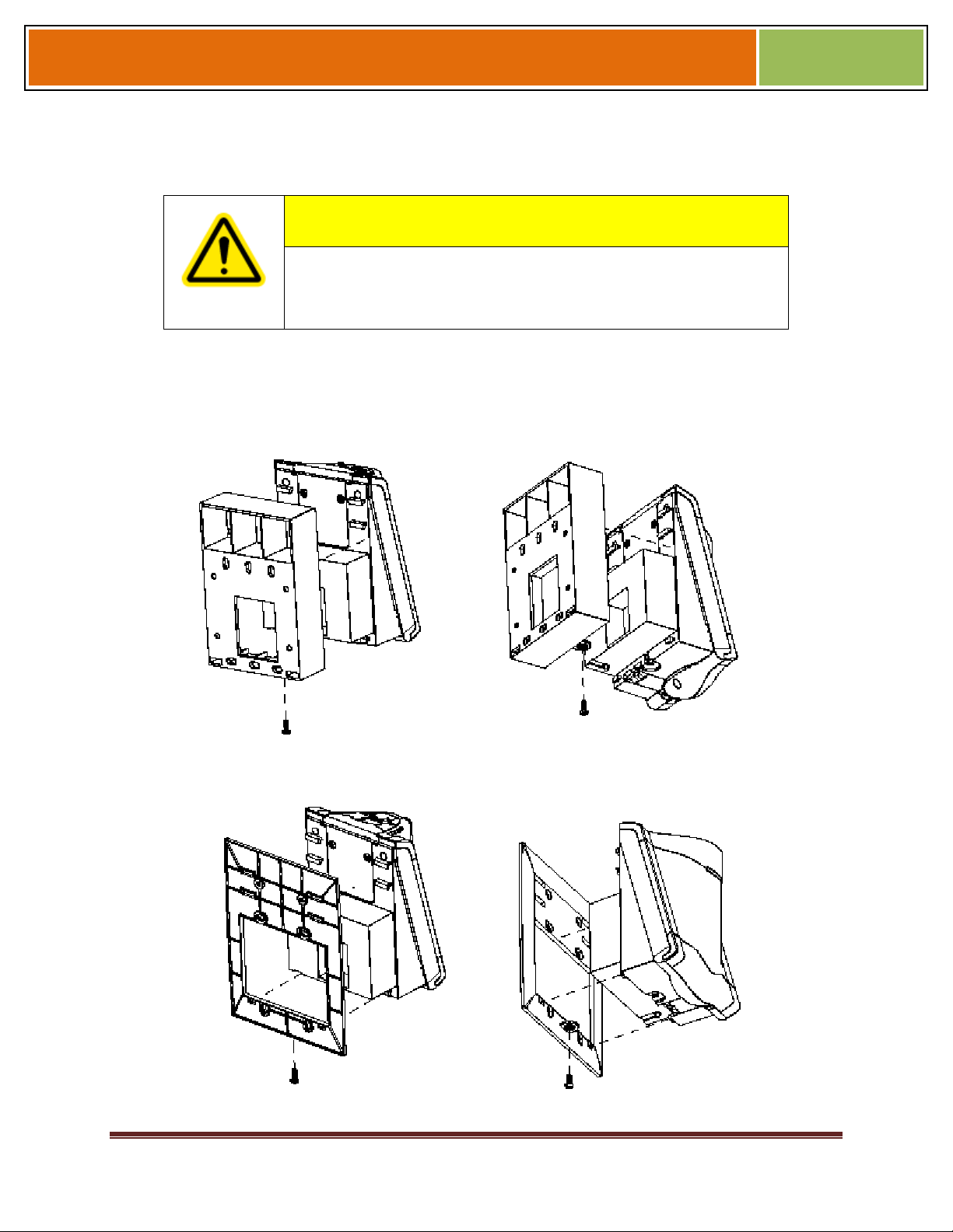
4.1.2 INSTALLING A MOUNTING PLATE
The procedure for mounting a wall plate directly to a wall is as follows:
Hold the mounting plate onto the wall in the desired location, trace the square hole that
will be cut out, and mark the mounting screw locations. Note that for the V-Flex 4G,
the large square hole is at the bottom and for the V-Station 4G the hole is to the
right.
Cut out the square hole with a jigsaw or drywall saw. If the V-Flex 4G device is to be
recess-mounted, cut out a hole in the drywall to accommodate the rear extension on
the device housing.
Drill holes for the nylon wall anchors and install them.
Fish wires through the wall to the square hole.
Align the hole in the wall plate with the hole in the wall.
Fasten the mounting plate to the nylon wall anchors in the wall with the provided
screws.
If the V-Flex 4G device is to be recess-mounted on an electrical box, a double gang box
is required to accept the rear extension of the housing.
If mounting the V-Station 4G device to an electrical box, attach the mounting plate to a
single
October 15 2009 – Installation Guide Draft – Edit Purposes Only Page 46
Installation Guide –April 2010
gang box and use wall anchors on the remaining four holes for additional security.
To install the mounting plate on to an electrical box, screw the mounting plate to the box
with the provided 6-32 screws.
When installing a recess-mounted V-Flex 4G device, be careful not
to damage the tamper switch, as careless handling can shear it off.
Figure 4-1 V-Flex 4G Flush-mount Mounting Plate
CAUTION
2010
Figure 4-2 V-Flex 4G Recessed-mount Mounting Plate
October 15 2009 – Installation Guide Draft – Edit Purposes Only Page 47
Installation Guide –April 2010
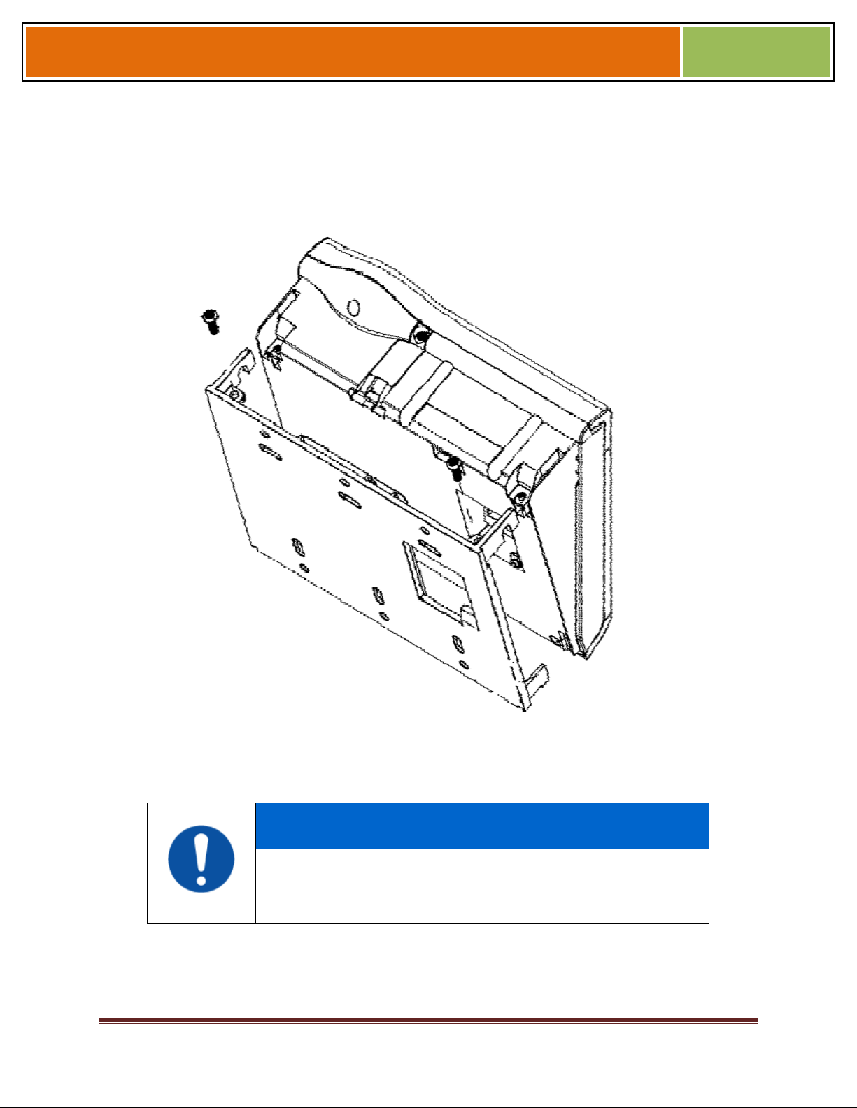
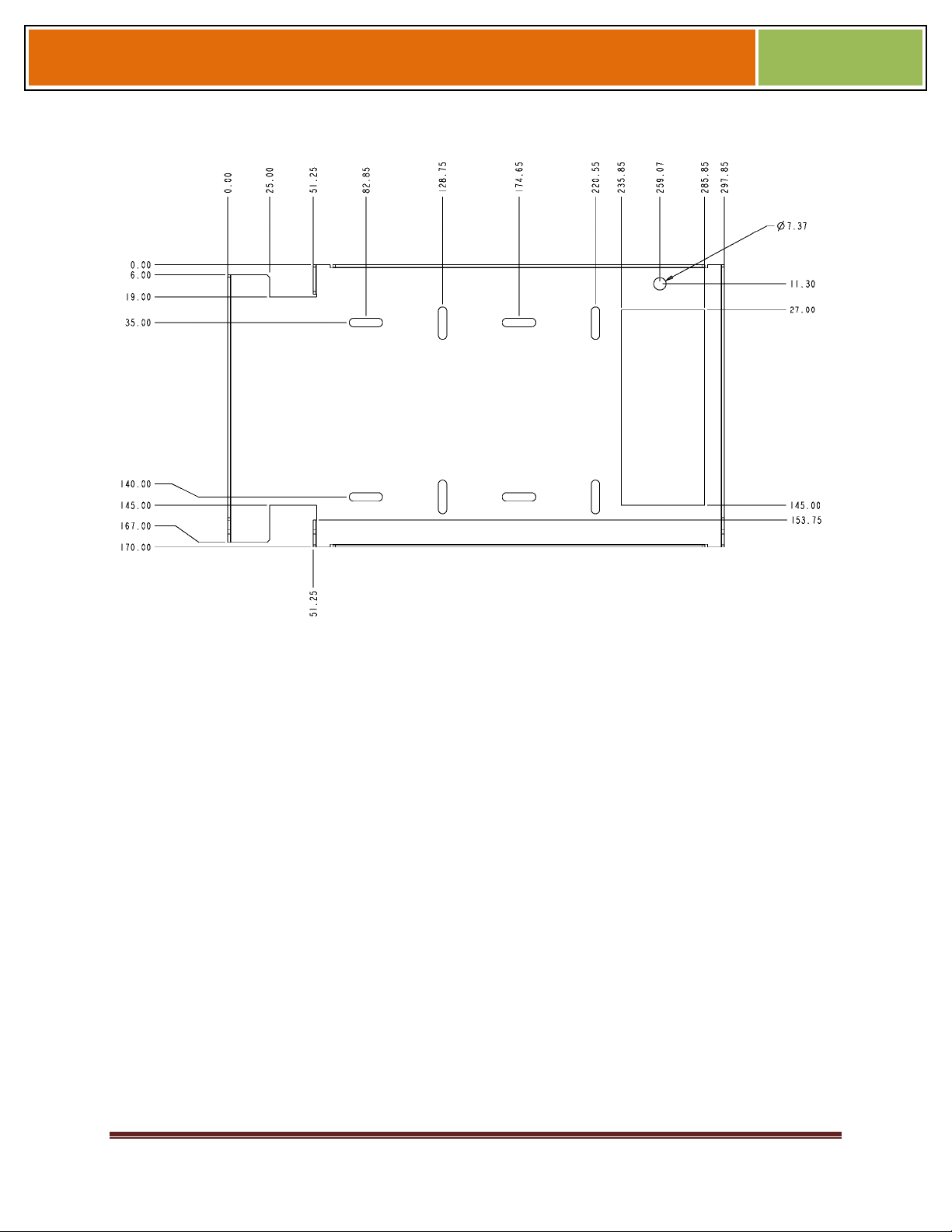
Figure 4-3 V-Station 4G Mounting Plate
2010
NOTICE
The V-Station 4G device can only be flush mounted.
October 15 2009 – Installation Guide Draft – Edit Purposes Only Page 48
Installation Guide –April 2010
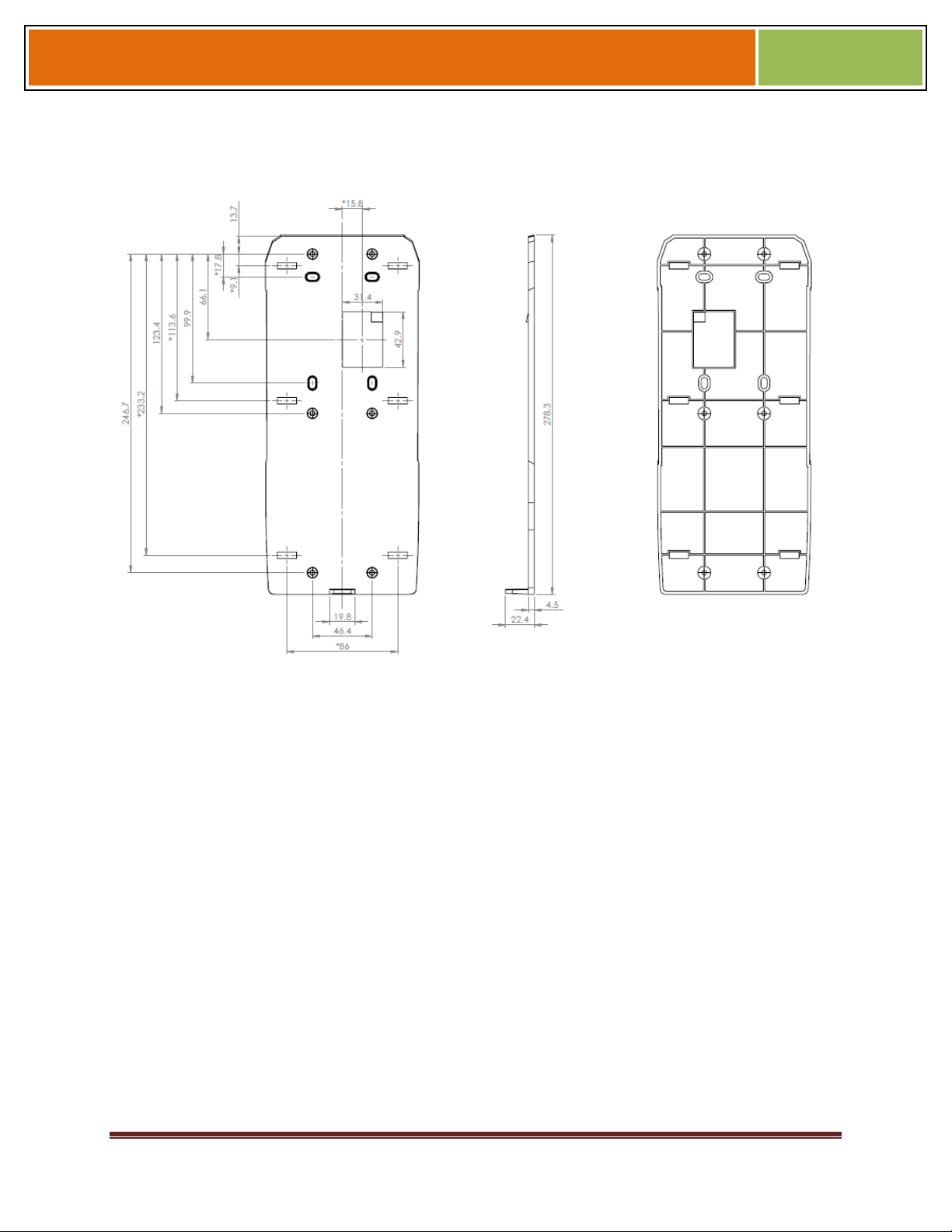
Figure 4-4 FingerVein Station 4G Mounting Plate
2010
October 15 2009 – Installation Guide Draft – Edit Purposes Only Page 49
Installation Guide –April 2010
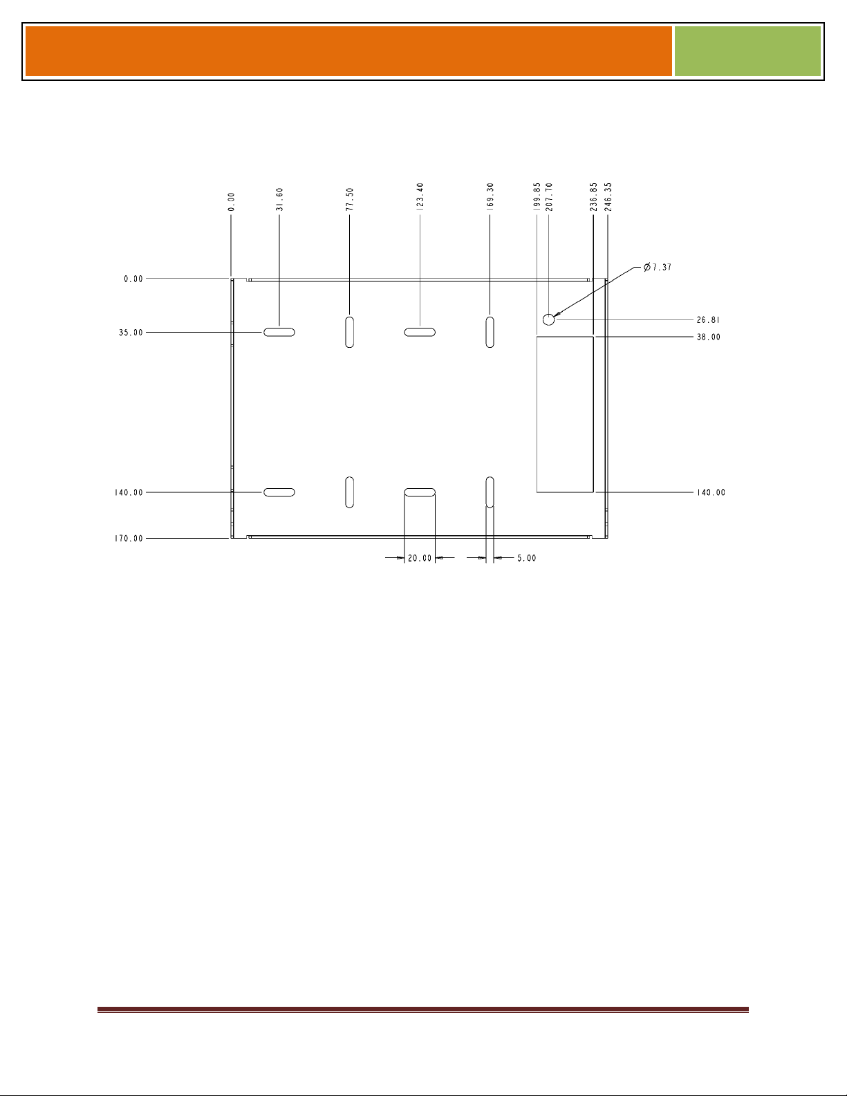
Figure 4-5 V-Station 4G Extreme Mounting Plate
2010
October 15 2009 – Installation Guide Draft – Edit Purposes Only Page 50
Installation Guide –April 2010
Figure 4-5 4G Extreme PIV/TWIC Mounting Plate
2010
4.1.3 INSTALLATION HARDWARE
4.1.3.1 4G V-Station and V-Flex Indoor devices
Quantity
1 Wall mounting plate/mullion mounting plate
6 #6-32 3/4" Philips pan-head screw
6 #6 1" Philips pan-head self-tapping screws
6 #4-8 1" nylon wall anchors
The hardware shown above is provided to mount the mounting plate to the wall and the
V- Station 4G or V-Flex 4G device to the mounting plate.
4.1.3.2 4G Extreme Devices
1 Stainless Steel, Wall Mount Plate
8 wall mount anchor, conical, for #8 screws
6 6-32 Security Screw 1/8" pin-in-hex 3/8" length
October 15 2009 – Installation Guide Draft – Edit Purposes Only Page 51
Installation Guide –April 2010
8 #8x1" thread forming screw, pan head, Philips
8 wall mount anchor, conical, for #8 screws
4.1.4 ATTACH DEVICE TO MOUNTING PLATE
4.1.4.1 4G V-STATION AND V-FLEX INDOOR DEVICES
Once all the electrical connections have been made to the device, it can be attached to
the mounting plate as follows:
For the V-Flex 4G, insert the four hooked protrusions on the rear of the device into the
corresponding slots on the mounting plate. Hold the device against the plate and gently
press it in a downward direction to engage the hooks. Insert the star-shaped screw at
the bottom center of the mounting plate and tighten with the wrench provided. Do not
over-tighten.
For the V-Station 4G, hold the device with the top slightly tilted toward you, at about a
30-degree angle to the wall. Hold the bottom of the device against the mounting plate
and lower it so that the two hooks on the bottom of the mounting plate engage the
corresponding slots on the device. When the hooks are properly engaged, the top of the
device can be pivoted up against the mounting plate. It will drop down slightly, locking
itself in the closed position, and should be secured in this position with the star-shaped
screws in the holes at the right and left ends on the bottom of the device. Do not overtighten.
2010
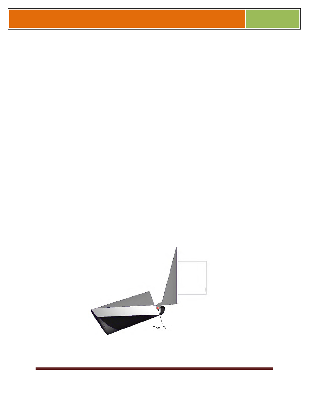
With the securing screws removed, the V-Station 4G device can be pivoted down 90
degrees from the wall, to allow access for making connections, etc. The device can be
removed from the mounting plate by tilting it at an angle approximately 30 degrees to
the wall and gently lifting it up off the hooks on the mounting plate.
Figure 4-6 Device Open for Installation or Service
4.1.4.2 4G EXTREME DEVICES
TBD
October 15 2009 – Installation Guide Draft – Edit Purposes Only Page 52
Installation Guide –April 2010
4.1.5 CONNECT DEVICE TO POWER SOURCE
The V-Station 4G and V-Flex 4G, and 4G Extreme devices can be powered by 12V-24V
DC power sources, or through a Power Over Ethernet (PoE) injector for V-Station 4G
and V-Flex 4G.
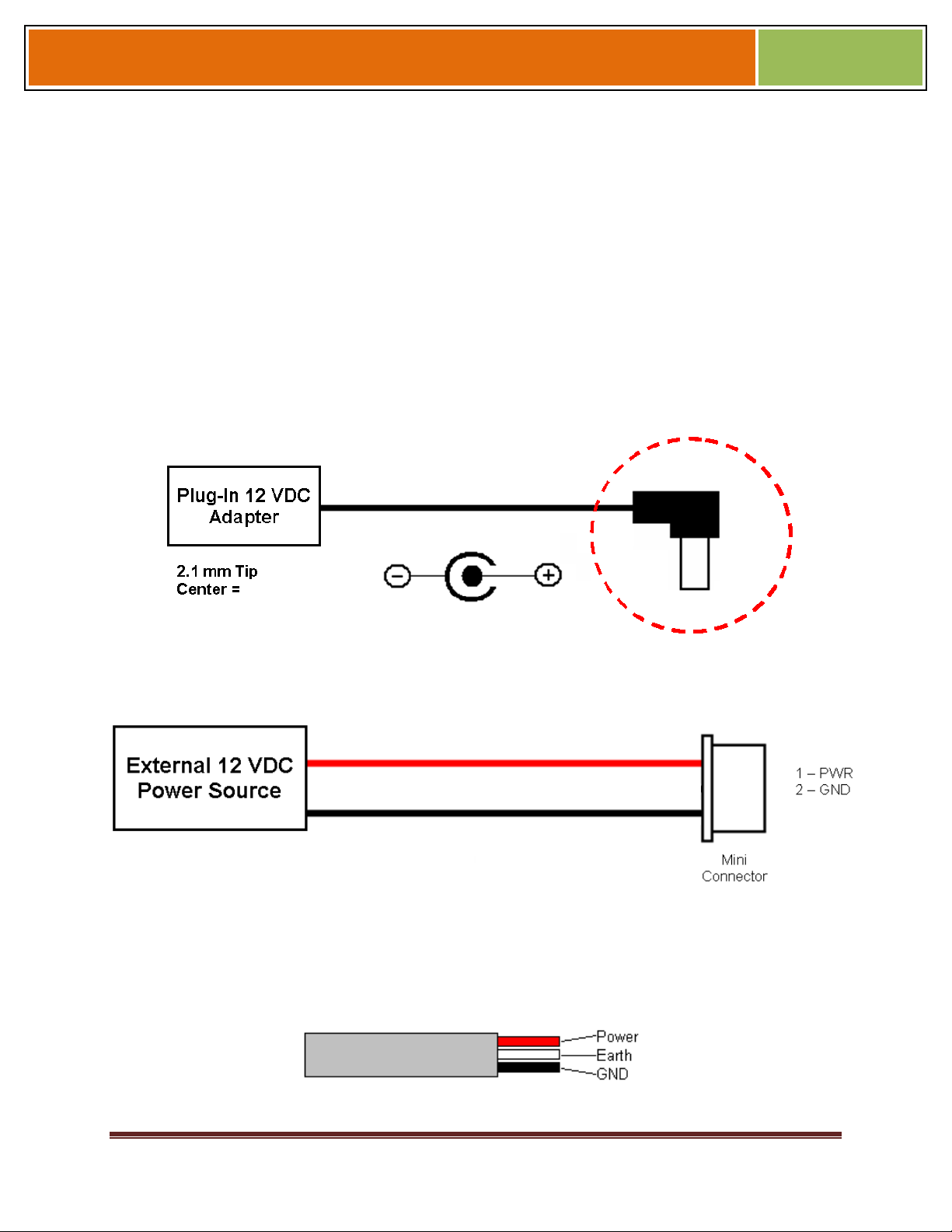
The two options for providing 1 2V power to V-Station 4G and V-Flex 4G devices are by
using an external wall plug-in adapter (Figure 4-7), or through external wiring and a mini
plug (Figure 4-8).
12V power can be provided to 4G Extreme devices only through the 3-Wire back cable
(Figure 4-9).
Figure 4-7 Connections for an External Wall Adapter (4G Indoor)
2010
Figure 4-8 Connections for an External Power Source (4G Indoor)
Figure 4-9 Connections for an External Power Source (4G Extreme)
October 15 2009 – Installation Guide Draft – Edit Purposes Only Page 53
Installation Guide –April 2010
The V-Station 4G, V-Flex 4G devices both support Power over Ethernet (PoE), using
their RJ-45 Ethernet interface. When these devices are to be powered over Ethernet, an
IEEE 802.3af compliant Active Midspan Injector must be used. Such an injector is not
supplied with L-1 Identity Solutions products. An example of a suitable PoE injector is
Model No. AT-61 01 G from Allied Telesis Inc. (http://www.alliedtelesis.com).
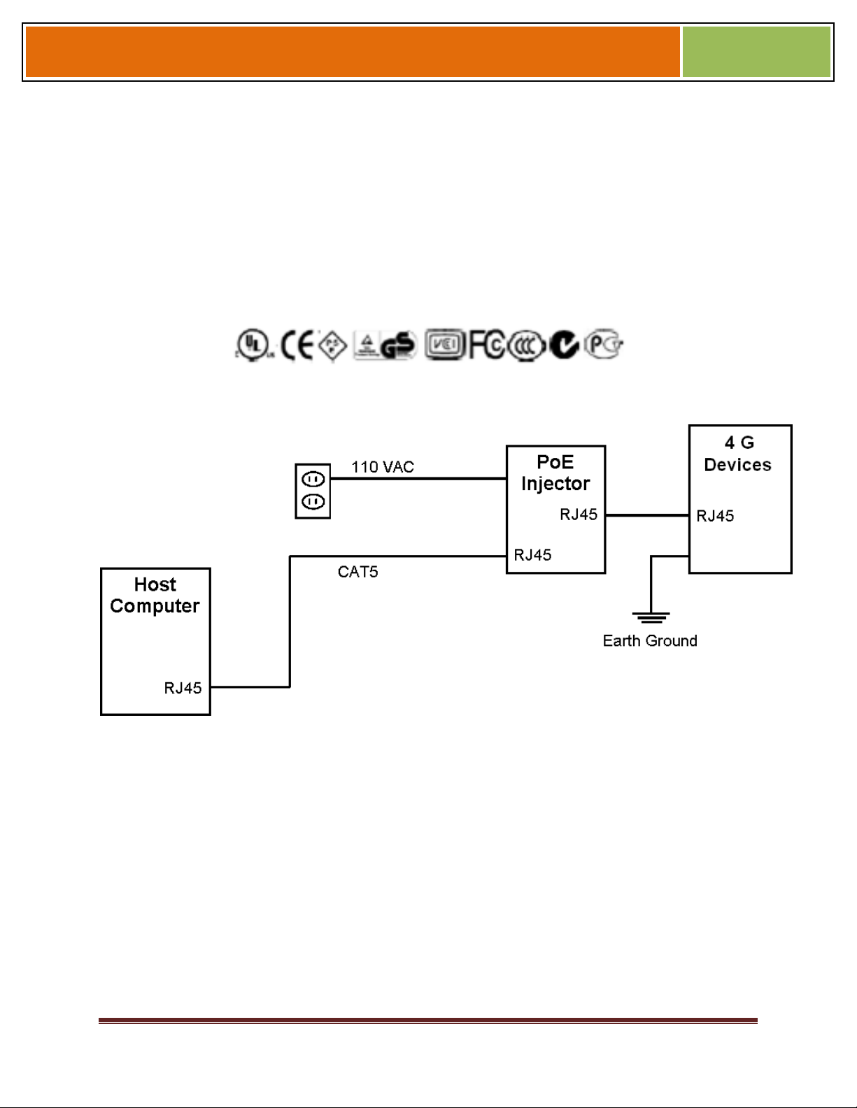
Any such device should carry at least one of the certifications shown below and should
be FCC listed.
Figure 4-11 Power Over Ethernet Connection
Figure 4-10 Certification Marks
2010
Specifications for suitable PoE Injectors for 4G Indoor devices are as follows:
Input voltage: 90-264 VAC, 60 Hz
Input current: 0.4A @ 100 VAC
Output voltage: -48 VDC
Output current: 0.32A
Power: 15.36 W
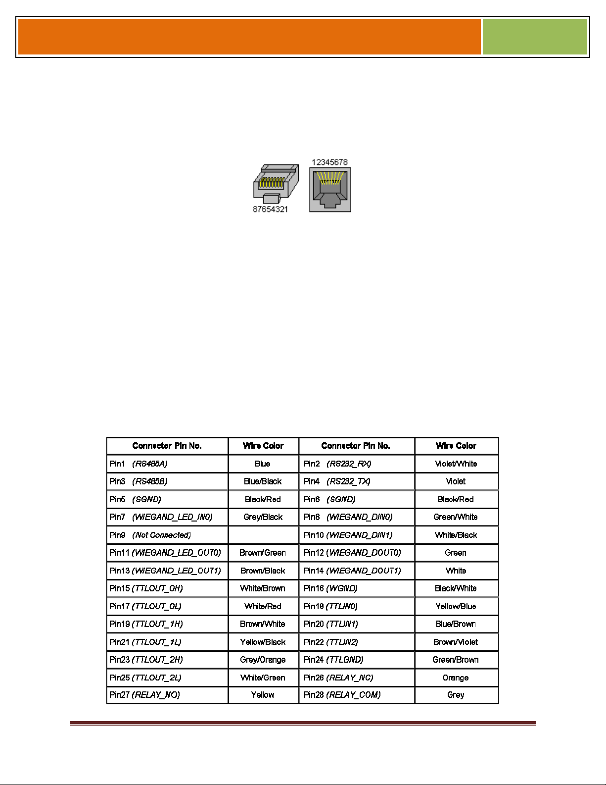
For Power over Ethernet, RJ-45 pin numbers 4, 5 are considered VB1 (+) positive DC
supply, and pin numbers 7, 8 are VB2(-) DC return.
October 15 2009 – Installation Guide Draft – Edit Purposes Only Page 54
Installation Guide –April 2010
Detailed RJ-45 pin assignments for PoE are given in Table PoE Pin Assignments, and
the physical location of the pins in the RJ-45 connector.
4.1.6 CONNECT DEVICE TO NETWORK
The V-Station 4G and V-Flex 4G devices support both RS-232/RS-485 and Ethernet 1
0baseT and 1 00baseTX network protocols.
4.1.6.1 ETHERNET NETWORK CONNECTIONS
Figure 4-12 RJ45 Pin Location
2010
Ethernet connections to the device are made through a standard RJ-45 connector on
the back of the device.
4.1.6.2 RS-232/RS-485 NETWORK CONNECTIONS
To connect a device to an RS-232 or RS-485 network, connect the appropriate wires to
the provided pigtail in accordance with the pin-out diagram.
Table 4-1 Pin-out Diagram
October 15 2009 – Installation Guide Draft – Edit Purposes Only Page 55

Installation Guide –April 2010
When connecting the device to the network, the following procedures must be followed:
Use Category 5 cabling with a characteristic impedance of 120 ohms
for RS-485 networks. Category 5 cables with a characteristic
impedance of 100 ohms can also be used, but with lower performance.
Cable manufacturers provide cables with multiple twisted pairs
designed for this type of communication (characteristic impedance is
120 ohm).
Unused pairs within the cable must be terminated with characteristic
impedance (100 or 120 ohm) on both ends.
AWG 24 should be considered as the minimum gauge.
Choose one twisted pair of conductors to use for RS-485 differential
connections, other conductors should be used for Signal Ground (RS485 GND on Weidmuller connection).
2010
The RS-232 to RS-485 converter must support Sense Data to be able
to switch from Send to Receive mode.
Check each device's cabling for ground faults before connecting to an
RS-485 network.
Each device should have pin 3 of the mini-connector connected to
earth ground.
After all devices are configured and connected to the RS-485 network, the baud rate
can be increased to the highest supported rate (some experimentation might be
required).
4.1.6.3 WIRELESS NETWORK CONNECTIONS
After the physical installation, the device can be configured for wireless network
connection. The wireless network can be set up either through SecureAdmin (see
Chapter 7 in the Operator's Manual) or through the front panel of the V-Station 4G
device.
To set up wireless operation through the front panel of a V-Station 4G device, perform
the following steps:
2. Power up the device.
Ensure that the wireless network is functioning.
Use one of these supported modes:
WEP Open
WPA Personal
October 15 2009 – Installation Guide Draft – Edit Purposes Only Page 56
Installation Guide –April 2010
WPA2 Personal.
L-1 Identity Solutions does not recommend using the "No
encryption" mode.
Enter the Admin menu on the device by pressing the Left arrow and Enter keys
simultaneously.
Key in the Admin password (default is "0000") and press OK.
Select the Communications icon and press OK
Select "Network Interface" and press OK.
Select "WLAN" Configuration and press OK.
NOTICE
2010
Select Managed/Adhoc mode from WLAN Network type.
Select the intended wireless networks.
Enable WLAN mode from WLAN parameters.
Choose Encryption mode and encryption .
Enter the key.
Select "DHCP" or "Static" and press OK. If you selected "DHCP", the device reboots.
Afterwards, it will have a dynamic IP address. If you selected "Static IP", specify an
IP, a Net Mask, a Gateway, and then press OK.
SecureAdmin can scan for and auto-detect wireless devices. If you want to use
SecureAdmin to scan for wireless devices, ensure that the "multicasting" option is
enabled in your router.
NOTICE
The maximum recommended distance from an access point is 25
feet.
4.1.7 SINGLE-DOOR CONTROLLER INSTALLATION
The V-Station 4G and V-Flex 4G devices incorporate an internal relay that enables
them to operate a deadbolt/door strike directly.
October 15 2009 – Installation Guide Draft – Edit Purposes Only Page 57
Installation Guide –April 2010
The internal relay is limited to a maximum current of 170 mA. If the
deadbolt/ doorstrike to be controlled draws more than 170 mA,
damage to the device may occur. If the deadbolt/door strike load
exceeds 170 mA, an external relay must be used, as described
below. Do not use the same power supply to power a V-Series 4G
device and a door strike.
Assuming the current drawn by the deadbolt/door strike is less than 170 mA, the
connections between the V-Station 4G or V-Flex 4G device, deadbolt/door strike, and
power supply for the deadbolt/door strike should be made. Note that a snubber diode (1
N4007 or equivalent) must be connected across the deadbolt/door strike to protect the
DC power supply from inductive kickback.
WARNING
CAUTION
2010
The snubber diode and DC power supply for the deadbolt/door strike
are not supplied with the V-Station 4G and V-Flex 4G devices. The
power supply should be specified in accordance with the voltage and
current requirements of the deadbolt/door strike, but it must be
ensured that the current to operate the dead bolt/door strike does
not exceed 170 mA.
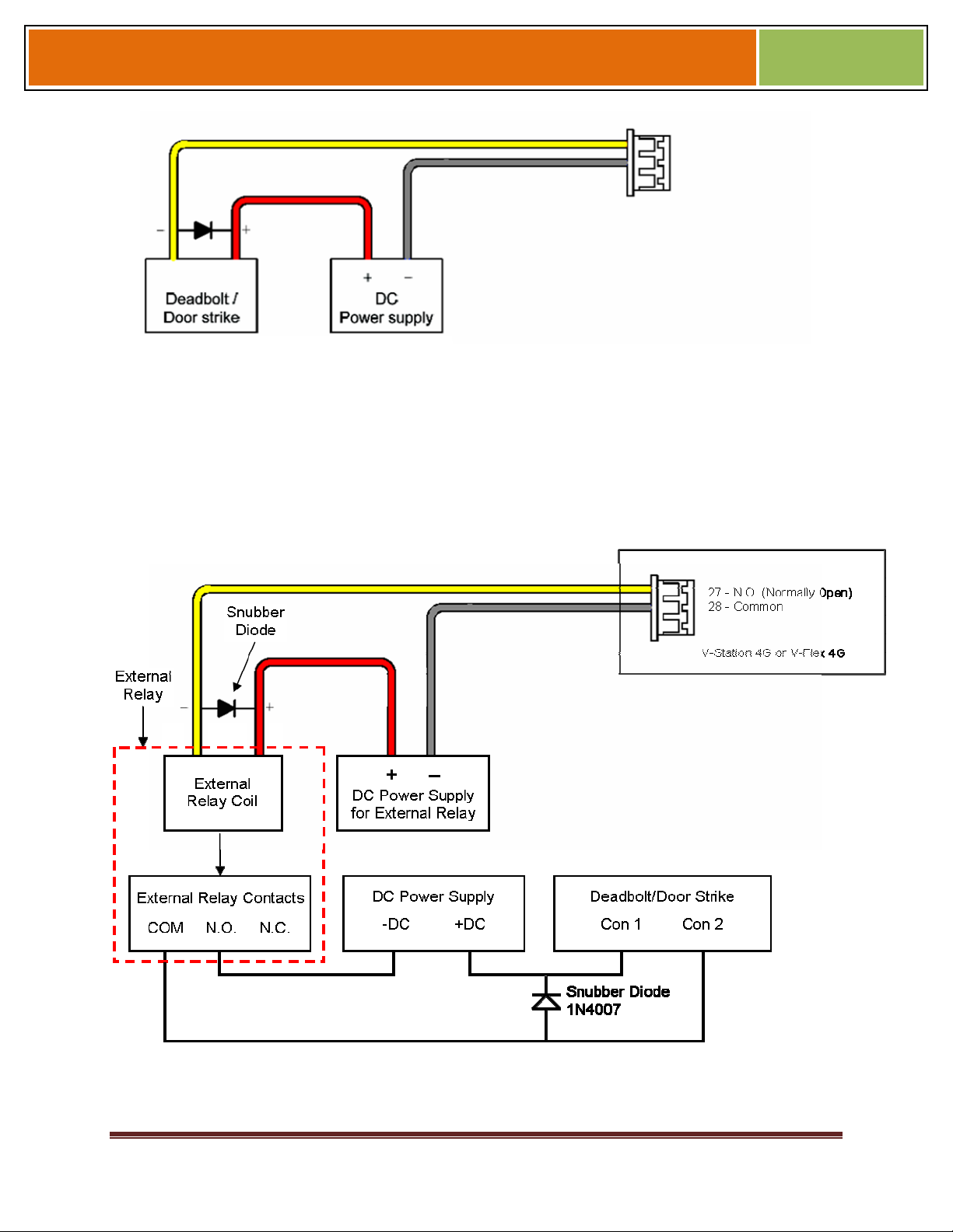
If the current required to operate the deadbolt/door strike exceeds 170 mA, an external
relay must be used in conjunction with the V-Station 4G or V-Flex 4G device. The
external relay must be specified so that its contacts are rated to carry the current
required by the deadbolt/door strike, and that the current required to operate its
energizing coil is within the 170 mA capacity of the V-Station 4G or V-Flex 4G device's
internal relay.
Figure 4-13 Connections for Internal Relay Operation
October 15 2009 – Installation Guide Draft – Edit Purposes Only Page 58
Installation Guide –April 2010
The power supply for the external relay must be chosen to match the operating voltage
and current of the external relay coil, but its voltage must not exceed the V-Station 4G
or V-Flex 4G device's internal relay maximum voltage rating of 250 volts.
The external relay should be connected. Note that snubber diodes (1 N2007 or
equivalent) should be connected across the external relay coil and the deadbolt/door
strike.
2010
Figure 4-14 Connections for External Relay Operation
October 15 2009 – Installation Guide Draft – Edit Purposes Only Page 59

Installation Guide –April 2010
4.1.8 AUX PORT
The Aux port is a USB 2.0 auto-negotiate connector located on the bottom of the
device. To access the Aux port, the Aux port door must first be removed. Use the
provided pin-in-hex security key to remove the #6-32 security screw retaining the plastic
Aux port door. Gently remove the plastic Aux port door to reveal the USB connector.
To attach a USB memory key or other "gadget" serial device by way of the Aux port,
use the USB Type A female to USB Micro A/B male adapter cable provided in the
installation kit.
The Aux port is used to transfer files to and from the device. Audio, images, firmware,
logs, and configuration files can be transferred quickly and easily to a device without the
need for a computer.
2010
CAUTION
Current rating of the Aux port is not to exceed 100 mA Maximum.
Figure 4-15 Location of Aux Port (V-Station 4G)
October 15 2009 – Installation Guide Draft – Edit Purposes Only Page 60

Installation Guide –April 2010
Figure 4-16 Location of Aux Port (FingerVein Station 4G)
2010
October 15 2009 – Installation Guide Draft – Edit Purposes Only Page 61

Installation Guide –April 2010
Figure 4-17 Location of Aux Port (4G Extreme)
2010
Figure 4-18 USB Memory Key
4.1.9 INSTALL FERRITE CORE
In order for the V-Station 4G and V-Flex 4G devices to comply with FCC Class B &
CISPR 22 Class B regulations, the installer and/or end user is required to use the
supplied Ferrite Material on the Ethernet, DC, and all I/O cables exiting the rear of the
device. This ferrite material is located within the installation kit that is supplied with each
product.
October 15 2009 – Installation Guide Draft – Edit Purposes Only Page 62

Installation Guide –April 2010
Ethernet Ferrite P/N: STEWARD 28A2432-0A2 DC & I/O Lines P/N: STEWARD
28A4155-0A2
Install the ferrite cores as close to the device as possible.
Figure 4-18 Installation of Ferrite Cores
2010
October 15 2009 – Installation Guide Draft – Edit Purposes Only Page 63

Installation Guide –April 2010
CHAPTER 5 - SYSTEM START-UP
PROCEDURES
CHAPTER OVERVIEW
This chapter explains the various start-up procedures and checks that should be
performed before applying power to a device.
Chapter Index
5.1 SYSTEM START-UP PROCEDURES
To avoid the need for difficult troubleshooting, system start-up must follow this step-bystep procedure. Never wire up a system and apply power to it all at once.
2010
SYSTEM START-UP OVERVIEW
L-1 Identity Solutions recommends always following these system start-up steps:
Do not apply power to any device.
Check all wiring and device configurations.
Disconnect all devices from the communication line.
Check the supply voltage for correct voltage.
Power up the PC running SecureAdmin.
Power up the RS-232 to RS-485 converter (if installed).
Configure SecureAdmin.
Perform a ground fault check for the converter (if installed).
Connect the PC and converter (if installed) to the communication line.
Verify that the device powers up correctly, but do not connect it to the communication
line. The power LED should be illuminated. Check the power lines with a voltmeter.
Perform a ground fault check for the device (if using RS-485, see below).
Connect the device to the communication line.
Verify that the device communicates with SecureAdmin.
If there are more device, repeat Steps 10 through 13 for each device.
5.1.1 DEVICE CONFIGURATION CHECK
Devices must be configured correctly before they can communicate. Common problems
include incorrect Host Port Protocol settings, mismatched Baud rates, and incorrect
October 15 2009 – Installation Guide Draft – Edit Purposes Only Page 64

Installation Guide –April 2010
device Net-work IDs. Each device sharing a communication line must have a unique
device Network ID.
5.1.2 RS-232 TO RS-485 CONVERTER GROUND FAULT CHECK
Before a device can be connected to an RS-485 subsystem, it must be checked for
ground faults. An uncorrected ground fault can damage all devices connected to the
RS-485 communication line.
To check for a ground fault on the RS-232 to RS-485 converter:
3. Apply power to the RS-232 to RS-485 converter.
Connect the signal ground of the RS-485 line through a 10k ohm current-limiting resistor
to the signal ground of the RS-232 to RS-485 converter. There should be no more
than 1 volt across the resistor.
5.1.3 DEVICE GROUND FAULT CHECK
To check for a ground fault on a new V-Station 4G or V-Flex 4G device:
2010
4. Apply power to all devices already successfully connected to the RS-485 line.
Power up the new device but do not connect it to the RS-485 line.
Connect the signal ground of the RS-485 line through a 10k ohm current-limiting resistor
to the signal ground of the V-Station 4G device.
There should be no more than 1 volt across the resistor. If there is, find and clear the
fault.
Repeat Steps 1 through 3 with each of the RS-485 signal lines (+ and -).
Connect the new device to the RS-485 line only if no ground fault is found.
October 15 2009 – Installation Guide Draft – Edit Purposes Only Page 65

Installation Guide –April 2010
6.1 CONFIGURE DEVICE
V-Station 4G and V-Flex 4G devices must be configured before use. This includes
setting various communication parameters and calibrating the device's sensor
6.1.1 REGISTER DEVICE
After a device is physically installed, it must registered. This can be done several ways -
- when a device is connected by means of a network (this is the recommended method),
or when the device is connected directly to the host computer upon which SecureAdmin
is running.
6.1.1.1 TO REGISTER A NETWORKED DEVICE
Launch SecureAdmin.
Double-click the Network tab. Three buttons are displayed.
2010
Figure 6-1 Network Sidebar Tab
Click the Register via Server button. A Register via Server dialog box is displayed.
October 15 2009 – Installation Guide Draft – Edit Purposes Only Page 66

Installation Guide –April 2010
Figure 6-2 Register via Server Dialog Box
2010
Select the Search Automatically check box (UDP protocol must be enabled on the
net-work.
Click the Scan button. SecureAdmin scans the network for connected devices and lists
the results. Devices with "plus" signs in their icon are available to add.
In the list, click the icon of the device you want to register. The server communication
parameter dialog box is displayed. A Register Device dialog box is displayed.
Select the communication parameter (if connecting via RS-232 or RS-485), enter
the appropriate Port, Baud Rate, Device ID, and select the communication protocol
from the drop-down. If connecting via enter the network IP address of the device
(selectthe DHCP check box if dynnamic IP addressing is used).
Figure 6-3 Register Device Dialog Box
October 15 2009 – Installation Guide Draft – Edit Purposes Only Page 67

Installation Guide –April 2010
Enter a Device Name.
Select a Group.
Click Register. A Device Summary is displayed.
Figure 6-4 Device Summary Dialog Box
2010
Click OK.
Click Close. The device is registered.
6.1.1.2 TO REGISTER A DEVICE VIA A CLIENT
5. Launch SecureAdmin.
Double-click the Network tab. Three buttons are displayed.
Click the Register via client button. The Step 1 Find Device dialog box is displayed.
Figure 6-5 Step 1 Find Device Dialog Box
October 15 2009 – Installation Guide Draft – Edit Purposes Only Page 68

Installation Guide –April 2010
Select either Serial Port - this machine or Ethernet radio button.
Enter the appropriate connection details.
If you are connecting via USB/RS-232:
2010
Enter the appropriate Port Number (to determine the correct port number, look in the
Win-dows Device Manager for a "Gadget Serial" entry under the "Ports (COM & LPT)"
heading), Baud Rate, and Device ID.
If you are connecting via RS-485:
Enter the appropriate Port Number (to determine the correct port number, look in the
Win-dows Device Manager for your RS-485 entry under the "Ports (COM & LPT)"
heading), Baud Rate, and Device ID.
If you are connecting via Ethernet:
Enter the network IP Address of the device you want to connect to.
NOTICE
The first time a V-Station 4G or V-Flex 4G device is connected to the
computer via the USB/RS-232 interface, the Windows Found New
Hardware Wizard might start. As all required device drivers are
installed when Secu-reAdmin is installed, simply follow the prompts,
accepting the default choices when possible, to install the device.
Click Next. The Step 2 Device Information dialog box is displayed.
Figure 6-6 Step 2 Device Information Dialog Box
October 15 2009 – Installation Guide Draft – Edit Purposes Only Page 69

Installation Guide –April 2010
Click Next. The Step 3 Server Communication Parameter dialog box is displayed.
2010
Figure 6-7 Step 3 Server Communication Parameter Dialog Box
Select the radio button that corresponds how the server will connect to the device,
either by Serial Port or by Ethernet.
If connecting via RS-232 or RS-485, enter the appropriate Port, Baud Rate, and
Device ID and select the communication protocol from the dropdown. If connecting
via Ethernet, enter the network IP Address of the device (select the DHCP check
box if dynamic IP addressing is used).
Click Next. The Step 4 Register Device dialog box is displayed.
October 15 2009 – Installation Guide Draft – Edit Purposes Only Page 70

Installation Guide –April 2010
Figure 6-8 Step 4 Register Device Dialog Box
Enter a Device Name.
Select the Group the device will belong to from the drop-down menu.
Click Register. The Device Summary dialog box is displayed.
Figure 6-9 Device Summary Dialog Box
2010
October 15 2009 – Installation Guide Draft – Edit Purposes Only Page 71

Installation Guide –April 2010
CHAPTER 7 - MAINTENANCE AND
CLEANING
CHAPTER OVERVIEW
This chapter explains how to replace and calibrate the fingerprint sensor module, and
how to clean the device sensor.
7.1 MAINTENANCE AND CLEANING
The V-Station 4G and V-Flex 4G devices require very little in the way of daily
maintenance except for occasional cleaning and disinfecting. The V-Station 4G and VFlex 4G devices feature field-replaceable sensors.
2010
7.1.1 FIELD MAINTENANCE
V-Station 4G and V-Flex 4G fingerprint sensors can be replaced quickly and easily in
the field. The following sections explain in detail the steps required to replace a sensor.
7.1.1.1 DISARMING THE TAMPER PROTECTION
The Tamper Switch is a momentary push-button switch on the back of the device within
the I/O cable interface pocket.
The tamper protection feature allows the device to sound an audio alert, flash LEDs,
send a pre-defined Wiegand string to the control panel, or disable biometrics if the
tam-per switch is triggered.
Figure 7-1 Tamper Switch Location For V-Station 4G
October 15 2009 – Installation Guide Draft – Edit Purposes Only Page 72

Installation Guide –April 2010
With the wall mounting plate mounted and the device secured to the mounting plate, the
tamper switch is depressed, closing the electrical circuit. When the device is removed
from the wall by removing the security screws or in the event that the device is removed
from the wall by force, the tamper switch opens.
To access the tamper-protection setting on the V-Station 4G device using the keypad:
Enter the Admin menu on the device by pressing the Left arrow and Enter keys
simultaneously.
Key in the Admin password (default is "0000") and press OK.
Select the System icon and press OK.
Select Device Settings and press OK.
Select SDC/Tamper Settings and press OK.
Select Tamper Settings and press OK.
If the alarm has sounded, select Clear and Re-enable. The Tamper protection setting is
set to disabled by default.
2010
7.1.1.2 REPLACING THE SENSOR
The sensors can only be replaced with the same type as previously
used. L-1 EAS does not support changing the type of sensor.
Different types of sensors are not interchangeable, and the device
will fail to operate.
• Power to the device MUST BE DISCONNECTED prior to
servicing.
• If the device is secured to the wall please be sure to follow the
Disable instructions.
• Tamper settings prior to the removal of the device from the
wall.
• ESD protective handling procedures must be followed before
any service is applied to the device.
WARNING
NOTICE
October 15 2009 – Installation Guide Draft – Edit Purposes Only Page 73

Installation Guide –April 2010
7.1.1.2.1 V-FLEX 4G
To replace the sensor module in a V-Flex 4G device, follow these steps:
6. Remove the security screw and slide the V-Flex 4G device up until the hooks are
free from the wall-mounting plate.
Remove two Philips screws.
Gently slide the sensor back plate, sensor mask, and sensor out of the V- Flex 4G
device. Be careful not to damage any internal wiring.
Disconnect the sensor module wiring harness from the internal device connector. It
might be necessary to rock the connector back and forth to work it out. Do not pull
with excessive force as you might damage the mating connector.
Figure 7-2 Removal of Sensor Module from V-Flex 4G Device
2010
Disconnect the sensor module wiring harness from the sensor module. Do not damage
the wiring harness as it will be re-used with the new sensor module.
Reassembly is the reverse of disassembly.
CAUTION
The parts are assembled at the factory and are not meant to be
removed by the end user. Removing any of these parts will void the
warranty.
October 15 2009 – Installation Guide Draft – Edit Purposes Only Page 74

Installation Guide –April 2010
Figure 7-3 Non-Removable Parts (V-Flex 4G)
7.1.1.2.2 V-STATION 4G
To replace the sensor module in a V-Station 4G device, follow these steps:
2010
7. Remove the security screw.
Tilt the device at an angle approximately 90 degrees to the wall.
Remove the three Philips screws.
Figure 7-4 Removal of Sensor Module from V-Station 4G Device
Gently slide the sensor back plate, sensor mask, and sensor out of the V- Station 4G
device. Be careful not to damage any internal wiring.
October 15 2009 – Installation Guide Draft – Edit Purposes Only Page 75

Installation Guide –April 2010
Disconnect the sensor module wiring harness from the internal device connector. It
might be necessary to rock the connector back and forth to work it out. Do not pull
with excessive force as you might damage the mating connector.
Disconnect the sensor module wiring harness from the sensor module. Do not damage
the wiring harness as it will be re-used with the new sensor module.
Reassembly is the reverse of disassembly.
The parts shown are assembled at the factory and are not meant to
be removed by the end user. Removing any of these parts will void
the warranty.
Figure 7-5 Non-Removable Parts (V-Station 4G)
CAUTION
2010
7.1.1.3 CALIBRATING THE SENSOR
After a device sensor is replaced, it must be calibrated before it can be used (Only
available for UPEK sensors).
To calibrate a device:
8. Select Sensor Calibration in the Tools drop-down menu. The Calibration Wizard
appears.
October 15 2009 – Installation Guide Draft – Edit Purposes Only Page 76

Installation Guide –April 2010
Figure 7-6 Calibration Wizard Step 1 of 2 Dialog Box
2010
Select the device you want to calibrate in the Current Device menu.
Click Calibrate. Wait as the device sensor is calibrated.
Click Next. The Calibration Wizard Step 2 dialog box is displayed.
Figure 7-7 Calibration Wizard Step 2 of 2 Dialog Box
Click Capture.
October 15 2009 – Installation Guide Draft – Edit Purposes Only Page 77

Installation Guide –April 2010
Place a finger on the sensor, hold it, and remove it as directed by the on-screen
prompts. The capture results are displayed.
Figure 7-8 Calibration Wizard Capture Results Dialog Box
2010
Click Close. The device sensor is now fully calibrated and ready to use.
7.1.2 CLEANING
Sensors become soiled with residue, oils, or other contaminants due to contact with
fingers and exposure to the elements. The sensor surface should be cleaned
periodically for performance, aesthetic, and hygienic reasons. Care must be taken when
cleaning the sensor to prevent dam-aging the sensor surface or surrounding
components.
To clean the fingerprint sensor in a V-Station 4G or V-Flex 4G device:
9. Remove the electrical power from the device.
Moisten (do not saturate) a clean cotton swab or a lint-free cloth with rubbing (Isopropyl)
alcohol.
CAUTION
Do not use chlorine-based cleaners, such as bleach, or chlorinebased bath-room or mildew cleaners. Chlorine-based cleaners will
not adversely affect the fingerprint sensor, but they could damage
the electronic circuitry sur-rounding the fingerprint sensor
.
Do not use solvents such as acetone, methyl ethyl ketone, lacquer
thinner, etc. Solvents will not adversely affect the sensor, but they
are likely to damage the reader housing or other peripheral
components.
October 15 2009 – Installation Guide Draft – Edit Purposes Only Page 78

Installation Guide –April 2010
Never use products such as abrasive cleaning powders, steel wool,
scouring pads, or fine sandpaper to clean the sensor surface. These
types of cleaning products will damage the sensor surface.
Rub the sensor surface with the moistened cotton swab or lint-free cloth. Do not allow
the cleaning product to drip onto any electronic components near the sensor.
Rub the sensor with a clean dry cotton swab or lint-free cloth to remove any traces of
clean-ing product.
Reconnect power to the device.
WARNING
2010
NOTICE
Disposable ESD-safe wipes, such as ACL Staticide wipes, can be
used to disinfect the sensor and buttons on a daily (or even more
frequent) basis. Be aware that some wipes might not offer the same
cleaning power as the prod-ucts mentioned above and thus should
not be relied upon to thoroughly re-move all residue. Use of wipes
does, however, helps keep sensor and button surfaces hygienic and
makes an excellent complement to periodic cleaning.
October 15 2009 – Installation Guide Draft – Edit Purposes Only Page 79

Installation Guide –April 2010
CHAPTER 8 - TROUBLESHOOTING
CHAPTER OVERVIEW
This chapter information about any error messages that might be experienced during
the installation process.
8.1 TROUBLESHOOTING
8.1.1 INSTALLATION ERROR MESSAGES
These error messages might occur during the SecureAdmin installation process.
8.1.1.1 ERROR 1406 - INSUFFICIENT PRIVILEGES
2010
Figure 8-1 Error 1406
This error can occur during SecureAdmin Client installation at the last step (right before
"Finish"). If it occurs, it means that the user does not have sufficient rights to install
software on the computer.
October 15 2009 – Installation Guide Draft – Edit Purposes Only Page 80

Installation Guide –April 2010
Log off and log on either as a Administrator or another user that has sufficient privileges
to install software and perform the setup process again.
8.1.1.2 ERROR 27552 - ERROR CREATING DATABASE
Figure 8-2 Error 27552
2010
This error can occur during SecureAdmin Server installation process. If it occurs, it
means that the user does not have sufficient privileges to access a specific SQL
database.
Contact your IT department to ensure that your privileges are correct for the specified
database.
8.1.1.3 INVALID PASSWORD
Figure 8-3 Invalid Password
October 15 2009 – Installation Guide Draft – Edit Purposes Only Page 81

Installation Guide –April 2010
2010
This error can occur during SecureAdmin Server installation process on the User
configuration screen (after the database configuration screen).
If it occurs, it means that the password provided is not strong enough. Click OK, and
re-enter a password that is considered more secure. The password should be between
8 and 30 characters long and contain at least one capital letter, one number, and one
non-alphanumeric character.
October 15 2009 – Installation Guide Draft – Edit Purposes Only Page 82

Installation Guide –April 2010
8.1.1.4 ERROR 27502 - USER NOT ASSOCIATED WITH TRUSTED SQL SERVER
Figure 8-4 Error 27502 - User Not Associated
2010
This error can occur during the SecureAdmin Server installation process. If it occurs, it
means that the InstallShield Wizard could not access the specified SQL database.
Check your user name and password or contact your IT department to ensure that your
user name is associated with the specified SQL database.
October 15 2009 – Installation Guide Draft – Edit Purposes Only Page 83

Installation Guide –April 2010
8.1.1.5 ERROR 27502 - SQL SERVER DOES NOT EXIST
Figure 8-5 Error 27502 - Server Does Not Exist
2010
This error can occur during the SecureAdmin Server installation process (at the time of
database configuration, after the database selection screen). If it occurs, it means that
the InstallShield Wizard could not connect to the specified SQL database because it
does not exist or because the user is not authorized to access that database
Check your user name and password or contact your IT department to ensure that your
user name is authorized to access the specified SQL database.
October 15 2009 – Installation Guide Draft – Edit Purposes Only Page 84

Installation Guide –April 2010
8.1.1.6 INSUFFICIENT SYSTEM MEMORY
Figure 8-6 Insufficient System Memory
This error can occur during the SecureAdmin Server installation process at the first
screen after selecting server installation from the options screen.
If it occurs, it means that the computer you are trying to install SecureAdmin Server on
does not have sufficient system memory. Install more memory or install on a different
machine.
2010
8.1.1.7 OUT OF DISK SPACE
Figure 8-7 Out of Disk Space
October 15 2009 – Installation Guide Draft – Edit Purposes Only Page 85

Installation Guide –April 2010
This error can occur during the SecureAdmin Client installation process when
Secu-reAdmin starts to configure components, after the fingerprint feedback options
selection.
2010
October 15 2009 – Installation Guide Draft – Edit Purposes Only Page 86

Installation Guide –April 2010
9.1 CHAPTER 9 - NOTICES
The 4G lines of products have been tested for compliance with all applicable
international standards. The resulting approvals are listed below, and are additionally
printed on the labelling located on the rear panel of the product.
V- Flex 4G FCC, CE
V- Station 4G FCC, CE
PIV-TWIC Station 4G FCC, CE
FingerVein Station 4G FCC, CE
9.1.1 FCC Information to Users
This device complies with part 15 of the FCC Rules. Operation is subject to the
following two conditions: (1) This device may not cause harmful interference, and (2)
this device must accept any interference received, including interference that may
cause undesired operation.
2010
October 15 2009 – Installation Guide Draft – Edit Purposes Only Page 87

Installation Guide –April 2010
This equipment has been tested and found to comply with
the limits for a Class B digital device, pursuant to part 15 of
the FCC Rules. These limits are designed to provide
reasonable protection against harmful interference in a
residential installation. This equipment generates uses and
can radiate radio frequency energy and, if not installed and
used in accordance with the instructions, may cause
harmful interference to radio communications. However,
there is no guarantee that interference will not occur in a
particular installation. If this equipment does cause harmful
interference to radio or television reception, which can be
determined by turning the equipment off and on, the user
is encouraged to try to correct the interference by one or
more of the following measures:
NOTICE
2010
Reorient or relocate the receiving
antenna.
Increase the separation between the
equipment and receiver.
Connect the equipment into an outlet on a
circuit different from that to which the
receiver is connected.
Consult the dealer or an experienced radio/TV technician for help.
This Class B digital apparatus complies with Canadian ICES-003.
Applicable only to V-Station 4G, FingerVein Station and PIV-TWIC Station 4G
series product: This product complies with FCC radiation exposure limits set forth for
an uncontrolled environment. To comply with FCC RF exposure requirements, it must
be installed and operated in accordance with provided instructions. The unit requires
minimum 20cm (8inch) spacing between the unit and all persons’ body (excluding
hands and feet) during wireless modes of operation.
9.1.2 CE Information to Users
All Veri-Series 4G devices have the CE mark, for compliance with CISPR22/EN55022
requirements. For European Union (EU) countries, V-Flex 4G and V- Station 4G are
October 15 2009 – Installation Guide Draft – Edit Purposes Only Page 88

Installation Guide –April 2010
compliant with CE under the R&TTE Directive, related to the radio transceivers that are
part of their design.
9.1.3 Warning to Users
Changes or modifications not expressly approved by L-1 Identity
Solutions Inc. could void the user's authority to operate the
equipment.
CAUTION
2010
October 15 2009 – Installation Guide Draft – Edit Purposes Only Page 89
 Loading...