

Page 1
Quick Installation Guide
- Thunderbolt 2 model -
Quick Installation Guide
- Thunderbolt 2 model -
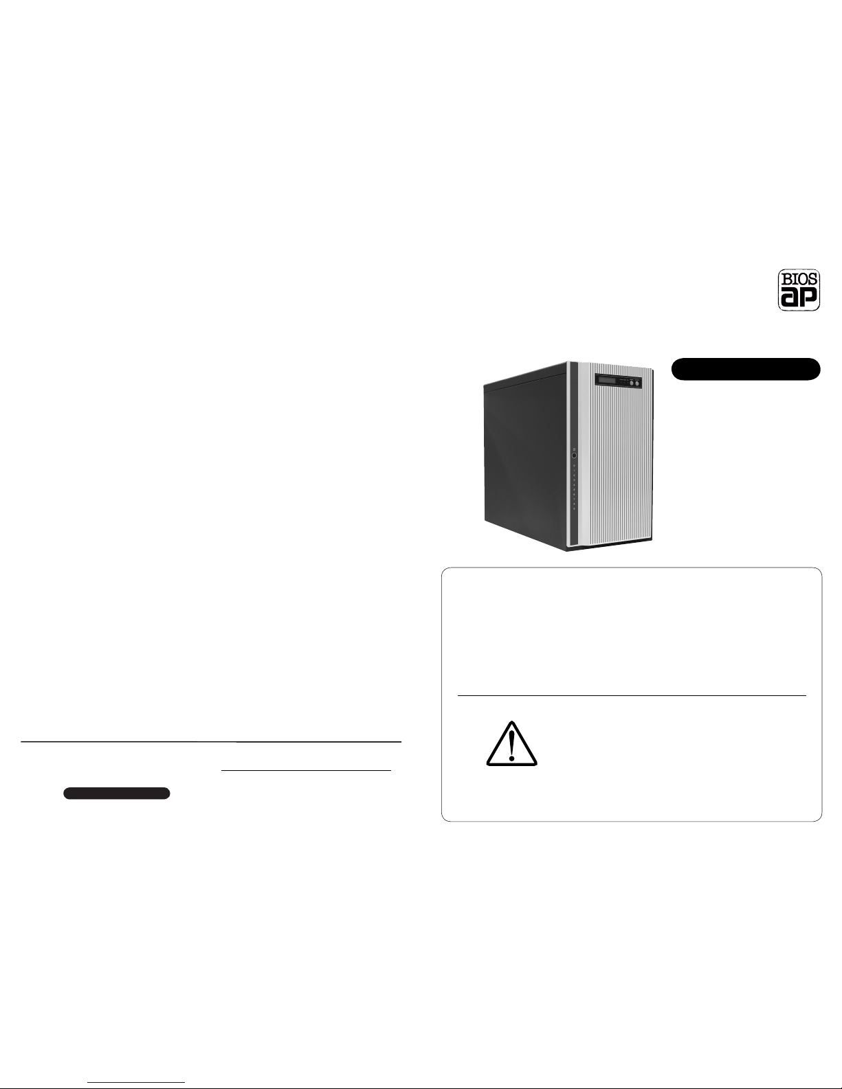
DVPro T10 - T2
DVPro T10 - T2
This Quick Installation Guide(QIG) describes the packing content and
installation guide line for DVPro T10-T2 / Thunderbolt 2 model.
It also explains the function of each connector, and button.
It is served as a quick startup for basic configuration, and the details
can be found on User Manual (CD-R).
BIOS AP and its resellers are not liable for any
data or information lost or possible software
error due to adoption of the product. We do not
take any responsibility of damage and/or system
malfunction due to our product / storage device
failure or for any of the problems caused as a
result It is recommended to always backup your
data.
◆ Introduction
Attention
World’s leading Thunderbolt 2 TM RAID 6 Storage
High Capacity, Quiet and High Performance
10 x 3.5” SATA Drive Support
DVPro T10 - T2 model
Apr. 2015 Printing No:02
Producer Yonezawa Shigeru
Publisher BIOS AP Inc.
6F-6A., No. 5, Sec. 3, New Taipei Blvd., Xinzhuang Dist.,
New Taipei City 242, Taiwan
TEL: +886-2-8522-8393 FAX: +886-2-8522-8323
Email: [email protected] Website: www.biosap.com.tw
Warranty Information
Page 2
SELECT
MODE
FAIL
ACCESS
POWER
◆ Packing List
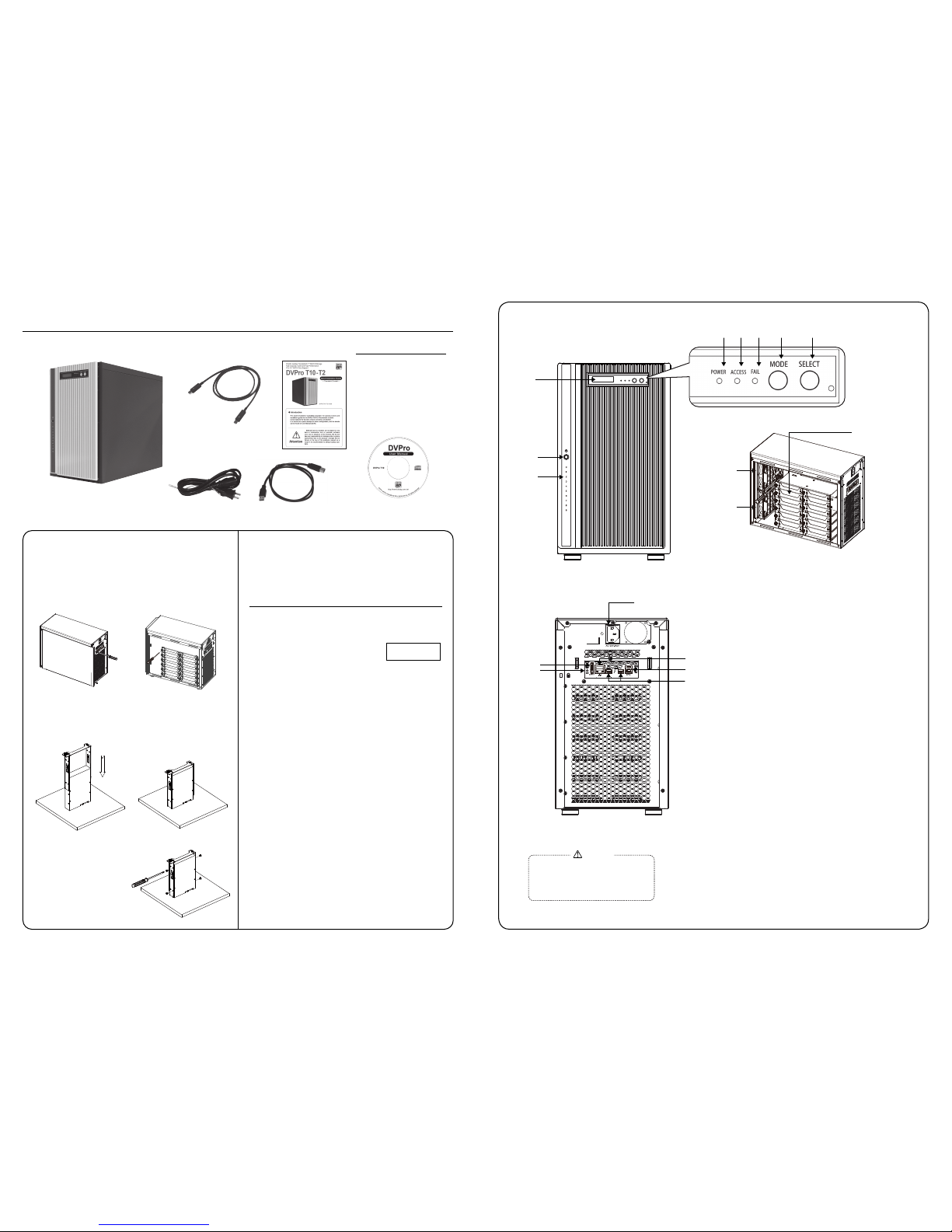
The box should contain the DVPro T10-T2 and below accessories:
DVPro T10-T2 Body
User Manual CD
( CD-R )
DVPro T10-T2
Quick Installation Guide
Power cable
Thunderbolt 2 cable
USB3 cable
◇ Packing List
● DVPro T10-T2 Body
● Power cable
● Thunderbolt 2 cable
● Screw Pack
● Quick Installation Guide
● User Manual CD( CD-R )
● USB3 Cable
● Thuderbolt cannot be enabled while USB3
/ eSATA is enabled.
● To have each LUN mapping to eSATA and
USB3, two LUN mapping and SWAP mode
should be configured.
Attention
◆ Name and Function of each part
< Front View >
< Rear View >
< Side View >
① POWER Switch
Power ON /OFF Switch
② HDD Access / FAIL LED
BLUE Flash upon access; Orange ON indicates an error
When「RAID-x RECOVERING 0%」shown on LCD,
the FAIL LED on means the HDD is under rebuilding
③ POWER LED
Power ON LED indicator
④ ACCESS LED
Host Access LED indicator
⑤ FAIL LED
A controller error LED indicator
⑥ MODE Button
1)Parameter Initialization ( Power on Initialization )
2)Configure parameters
3)Stop buzzer alarm ( Buzzer stopped immediately by pushing one time )
⑦ SELECT Button
Setup Parameter
⑧ LCD Display
Message display screen. Show status of the system
Show parameters while doing configuration
⑨ Power Inlet
AC Power Inlet
⑩ eSATA3 Connector
eSATA 6G host connector
⑪ USB3 Connector
USB3 host connector
⑫ Ethernet Port
RJ45 Fast Ethernet port for Web GUI management
⑬ Thunderbolt Connector
Thunderbolt 2 for host or cascade
⑭ Thunderbolt Connector
Thunderbolt 2 for host or cascade
⑮ INIT Button
Reserved for Controller Setup without front operational panel
⑯ Fan Module
Fan 1
⑰ Fan Module
Fan 2
⑱ Drive Module
Disk Drive module 0 ( to 9 ). Upper left one is number 0, and right is 1
To facilitate easy configuration of DVT10T2, a LCD/Keypad is designed on
the front panel for parameter setup. The default configuration and parameters
are designed to RAID6 mode. To avoid malfunction, parameters and configuration could not be changed on use. Open the small door on top of the front
panel to manipulate operational LCD panel.
Begin to use
There are two ways to configure the DVT10T2 setting either by Web GUI or
LCD and keypad operation. Most parameters cannot be changed during
normal operation to avoid possible corruption or
malfunction. To start with the parameter setting, both
‘Mode’ and ‘Select’ buttons have to be pressed and
hold at power on till the LCD showing [Array Parame-
ter Setting].
After then, one can change parameters value from Web GUI or LCD button
panel. To quickly setup the unit, press “Mode” button to roll among different
parameters and “Select” button to choose their values. After change, press
“Mode” and “Select” at the same time to save modified parameters.
For details of each parameter and its meanings, please refer to User Manual
CD.
The default setting might be varied for different configuration upon number
of pre-installed drives and capacity. Following parameters saved, please turn
off the power then press and hold the “Mode” button about 3 seconds while
turning on power to initialize the configured setting. New configuration or
parameters will be effective after initialization process.
Attention: Initialization process assumes data aligned to its RAID distribution
and will enforce current parameters to RAID controller. If the unit had corrupted data during last operation, the unit will be treated as normal despite of
possible uncompleted data.
For Drive installation if needed,
Follow the below instruction to install or replace disk drive.
Step 1.
Loosen the left side rear screws
(rear view)and open the side panel.
Step 2.
Use hand or screw driver to loosen
the thumb screw of disk drive tray.
Step 3.
Prepare a flat operating table for following operation. Put the disk drive perpendiculous to the flat table with the drive connector toward bottom(drive connector side facing you). With thumb screw of drive tray on left hand side, slide
down the tray carefully till it touches down the flat table.
Step 4.
Get four screws from the screw
bag and tightly screw them all.
ARRAY PARAMETERS
SETTING !
◆ Overview of Setup method
◆ Installation Guide
⑧
③
④ ⑤ ⑥ ⑦
①
⑭
⑬
⑮
②
⑩
⑫
⑨
⑪
⑰
⑯
⑱
 Loading...