


2

3
Contents
1. About this edition of user instructions ....................................................................... 3
2. Safety precautions ................................................................................................... 4
3. General information .................................................................................................. 6
4. Pre-installation requirements .................................................................................... 9
5. Getting started ........................................................................................................ 11
6. Operation ............................................................................................................... 19
7. Specifications ......................................................................................................... 23
8. Troubleshooting ..................................................................................................... 24
9. Care and maintenance ........................................................................................... 25
10. Warranty ................................................................................................................. 28
11. EU Declaration of conformity .................................................................................. 29
1. About this edition of user instructions
The current edition of user instructions applies to following models and versions of
water purification system:
Labaqua Trace ................................................................................. version V.1A01
Labaqua HPLC ................................................................................. version V.1A02
Labaqua Bio ..................................................................................... version V.1A03

4
2. Safety precautions
2.1. Symbols in the user instructions.
Caution! Make sure you have fully read and understood the present Manual
before using the equipment. Please pay special attention to sections
marked by this symbol.
Attention! Do not service the unit with a working UV compartment. Otherwise,
operator can receive dangerous levels of UV emission.
2.2. Symbols in the unit.
Grounding. This sign marks the area of electrical grounding.
Danger! Do not proceed further without reading the user and service instruc-
tions first.
High voltage! This sign indicates high voltage areas.
2.3. GENERAL SAFETY
The protection provided can be ineffective if the operation of the appliance does not
comply with the manufacturer's requirements.
After transportation or storage and before connecting it to the electric circuit, keep the
unit under room temperature for 2-3 hrs.
Save the unit from shocks and falling.
Store and transport the unit in a horizontal position (see package label) at ambient
temperatures between -20°C and +60°C and maximum relative humidity of 80%.
Before using any cleaning or decontamination methods except those recommended
by the manufacturer, check with the manufacturer that the proposed method will not
damage the equipment.
Use only original parts and accessories, provided by manufacturer for this product.
Do not make modifications in design of the unit.
Do not block the ventilation openings
Do not operate the unit with removed covers.
Do not drink deionized water.
2.4. WATER LEAKAGE PREVENTION
Ensure that no water tubes are bent.
Ensure that all connections are watertight.
Ensure that the drainpipe exit is lower than the drain fitting in the unit.
Install a particle filter on the water access pipe. Warranty does not cover malfunctions
of the unit if the filter is not installed.
Close off the water access pipe when leaving the unit for extended period.

5
2.5. ELECTRICAL SAFETY
Use a power line regulator if the local mains network is susceptible to fluctuations
exceeding 10% of the nominal values.
Connect only to the mains with voltage corresponding to that on the serial number
label.
When replacing fuses, re-check its placements.
Do not plug the unit into an ungrounded power socket, and do not use an ungrounded
extension lead.
Ensure that the power plug is easily accessible during use.
Disconnect the unit from the mains before moving.
If liquid penetrates into the control module, disconnect the unit from the mains and
have it checked by a repair and maintenance technician.
Do not operate the unit in premises where condensation can form. Operating condi-
tions of the unit are defined in the Specifications section.
2.6. DURING OPERATION
Do not operate the unit in environments with aggressive or explosive chemical mix-
tures. Please contact manufacturer for possible operation of the unit in specific atmospheres.
Do not operate the unit if it is faulty or has been installed incorrectly.
Do not use outside laboratory rooms.
2.7. BIOLOGICAL SAFETY
The user is responsible to carry out appropriate decontamination if hazardous mate-
rial spills on or penetrates into the equipment.

6
3. General information
Biosan Labaqua is Ultrapure water purification system which requires external water
tank that use tap water as feed water (tap water system). There are three models available:
Labaqua Trace, Labaqua HPLC and Labaqua Bio.
Water purification system Biosan Labaqua produces pure water that complies with
ISO 3696 Grade II and Grade I water requirements.
Pure (ISO 3696 Grade II) water applications include, but are not limited to:
Feed for laboratory equipment (washing machines, clinical analyzers, humidifiers,
autoclaves, hydrogen gas generators);
Manufacturing of chemical and biochemical reagents;
Buffer preparation;
Microbiological media preparation;
In some cases - sensitive analytical techniques (e. g. atomic absorption, ICP-OES);
Wet chemistry;
Spectrophotometry.
Ultrapure (ISO 3696 Grade I) water applications include but are not limited to:
High sensitivity analytical techniques (ICP-MS);
High performance liquid chromatography;
TOC analysis
Molecular biology;
Cell culture.
Table 1. Labaqua model comparison
Model
Labaqua Trace
Labaqua HPLC
Labaqua Bio
Grade I water resistivity
18.2 MΩ x cm
Grade I water conductivity
0.055 μS/cm
Grade II water conductivity
0.1 μS/cm
TOC
< 10 ppb
< 2 ppb
RNase
-
-
< 0.01 ng/mL
DNase
-
-
< 4 pg/μL
Bacteria
< 1 CFU/mL
< 0.01 CFU/mL
Endotoxins
0.15 EU/mL
0.001 EU/mL

7
3.1. Unit overview
Figure 1. Unit overview
1. Power switch (on the back panel) 2. Water access connection (on the back panel). 3. Control
panel and display. 4. Filter and clean water dispenser. 5. Pre-filter set, deionization and polish-
ing modules (behind side door)
Figure 2. Labaqua Trace scheme

8
Figure 3. Labaqua HPLC / Bio scheme
3.2. Operation principle.
3.3. The hydraulic diagram of the Biosan Labqua water purification system can be seen
in figures 2 and 3.
3.4. The input valve controls intake of feed water from the access. The first cleaning stage
is the pre-filter set that uses activated carbon to remove particles, free chlorine, organics and colloids. The pressure switch controls incoming water pressure.
3.5. The boost pump maintains pressure for the efficient operation of the reverse osmosis
membrane, deionization module and UV sterilization module (model Bio only). The
feed flow splits on the membrane into the permeate, which diffuses through the membrane, and the concentrate, which passes over the membrane, carrying away contaminants through the drain. The permeate proceeds to the deionization module
where the remaining dissolved contaminants are removed.
3.6. Before entering the tank, model Bio sterilizes the water with an UV lamp. Water quality is controlled by Grade II water conductivity sensor. LCD display shows these values.
3.7. Purified water is stored in the tank. Water in the tank meets the requirements of ISO
3696 Grade II.
3.8. To obtain Grade I water, the Grade II water in the storage tank must pass through a
recirculation loop. For model Trace this loop consists of a recirculation pump, a polishing module, a Grade I water sensor and a dispense port with microfilter. Models
HPLC and Bio additionally include a photooxidation module and a TOC monitor.
Model Bio has an ultrafilter instead of a microfilter.

9
4. Pre-installation requirements
4.1. Make sure the following pre-installation requirements are met before unpacking and
installing the unit.
Table 2. Input water requirements.
Type of feedwater
Potable
Minimum pressure
≥ 0.5 bar
Maximum pressure
≤ 5 bar
Conductivity
< 1300 µS/cm
Temperature
5 ... 35°C
pH
4 ... 10
Fouling Index
< 10
Iron
< 0.1 ppm as CaCO3
Aluminium
< 0.05 ppm as CaCO3
Manganese
< 0.05 ppm as CaCO3
Free chlorine
< 1 ppm
Langelier saturation index
< +0.2
TOC
< 2000 ppb
Water access connections
½" male NPTF
4.2. Filter and soften feedwater with polyphosphate-carbon 1 μm particle filter. If the filter
is not installed, pre-filter in the unit will clog and block the water flow. There must be
at least one filter on the feedwater access pipe. Filter is available in the local plumber
shops or by ordering at Biosan.
Figure 4. Filter on the water access pipe.
4.3. Water access connection.
4.3.1. Feedwater hardness affects water-cleaning quality. Using hard feedwater may result
in premature clogging of reverse osmosis membranes and reduced Grade II or Grade
I water output.
Attention Therefore, we strongly recommend installing a water softener or a
polyphosphate particle filter if water hardness is above 160 ppm.
4.4. Feedwater connection port has to be ½" NPTF male thread. The system is equipped
with feedwater tube (¼" outer diameter) and a ½" NPTF female adapter for water
supply connection. The feedwater tube should be connected to the ¼" John Guest
adapter in the unit. Feedwater connection pipe must have a valve to allow closing off
water supply.

10
4.5. Feedwater supply connector and drain should be within 3 meters from the unit location.
Attention Please note that if the pre-filter clogs prematurely, such malfunction
will be covered by warranty only of the service department receives
photographic proof of the particle filter installed in the feedwater access pipe.
4.6. Requirements for the installation site. Ensure that the unit is placed on a solid, level
surface not less than 320x560 mm, which is able to support its weight and the weight
of water inside the unit. The storage tank Pro requires at least 300x300 mm free
space. The tank during operation weighs up to 40 kg. The tank can be placed below
the unit. Ensure that all cables, tubes abd the power switch on the rear panel of the
unit are easily reachable.
4.7. Requirements for the environment. The water purification unit is intended for indoor
use only. Ensure that the site is maintained under the following conditions:
- Temperature ........................................................................ 15 to 30 °C (59 to 86 °F)
- Humidity ...................... 20% to 80% relative humidity, non-condensing atmosphere.
4.8. Water leakage safety:
- Ensure that no water tubes are bent.
- Ensure that all connections are watertight.
- Feedwater access and drain connections must be no farther than 3 m from the unit.
- Water access connector is ½" male NPTF.
Attention! Ensure that the storage tank is connected to the drain with a tube
from the OVERFLOW fitting. Ensure that the drain is lower than the
OVERFLOW fitting. This prevents water leakage in case of water
level sensor malfunction.
Attention! Ensure that the 1 μm particle filter is installed on the feedwater
access pipe. Failure to do so will lead to pre-filter clogging in the unit
and water flow restriction.

11
5. Getting started
5.1. Unpacking. Remove packing materials carefully and retain them for future shipment
or storage of the unit. Examine the unit carefully for any damage incurred during
transit. The warranty does not cover in-transit damage. Warranty covers only the units
transported in the original package.
Caution! Due to the high weight of the unit, its unpacking and installing must
be carried out by two persons.
5.2. Complete set. Package contents:
5.2.1. Standard set:
- Water purificatiom system, Labaqua Trace/HPLC/Bio .................................... 1 pce.
- Storage tank Pro .............................................................................................. 1 pce.
- Pre-filter cartridges ................................ ................................ ........................... 2 pcs.
- Polishing module .............................................................................................. 1 pce.
- Deionization module ......................................................................................... 1 pce.
- 0.22 μm filter dispenser (models Trace & HPLC) ........................................... 1 pce.
- Ultrafilter dispenser (model Bio) ..................................................................... 1 pce.
- Adapter from ½" NPTF to ¼" John Guest ........................................................ 1 pce.
- Straight angle fittings for polishing & deionization modules ............................. 4 pcs.
- Tubes, ¼" OD .................................................................................................. 5 pcs.
- Tube, ⅜" OD & straight angle fitting ................................................................. 1 pcs.
- Bypass tube for disinfection ............................................................................. 1 pce.
- Storage tank water level cable ......................................................................... 1 pce.
- Power cable .................................................................................................... 1 pce.
- Tool for tube detaching..................................................................................... 1 pce.
- Operation dongle .............................................................................................. 1 pce.
- Operating manual, declaration of conformity .................................................. 1 copy
5.2.2. Optional accessories:
- 1 μm particle filter , carbon ....................................................................... on demand
- 1 μm particle filter, polyphosphate-carbon .............................................. on demand
5.3. Ensure that the requirements listed in section 4. Pre-installation requirements are
met.
5.3.1. John Guest fittings (figure 5). Unit is equipped with push-in John Guest fittings
(henceforth JG), with clamps that hold a tube with steel teeth without deforming the
tube or blocking the flow. O-type sealing ring ensures hermetic seal.
To facilitate tube detachment, a special tool for clamp pressing is included in the
standard set.
Figure 5. John Guest type fitting and the tool for tube detaching.

12
5.3.2. Tube connection. Push the tube into the fitting to the stop (fig. 6/a) and tug back to
ensure the clamping (fig. 6/b).
a b
Figure 6. Connecting tubes
5.3.3. Disconnecting tubes. Ensure that the system is not under pressure. Press the clamp
sleeve on the fitting (fig. 7/1). This loosens the clamp and the tube can be detached
(fig. 7/2).
Note. Use the tool for tube detaching (figure 5, right) included in the stand-
ard set, for easier operation.
Figure 7. Detaching tubes
5.4. Side door and the rear panel. Side door provides access to installation sockets for
cleaning filters and modules (figure 8). Rear panel has inlet and outlet fittings and
sockets (figure 9).
Empty unit Work-ready unit
Figure 8. Filters and cleaning modules.
1. Deionization module socket. 2. Polishing module socket. 3. Pre-filter sockets.
13
Top Bottom
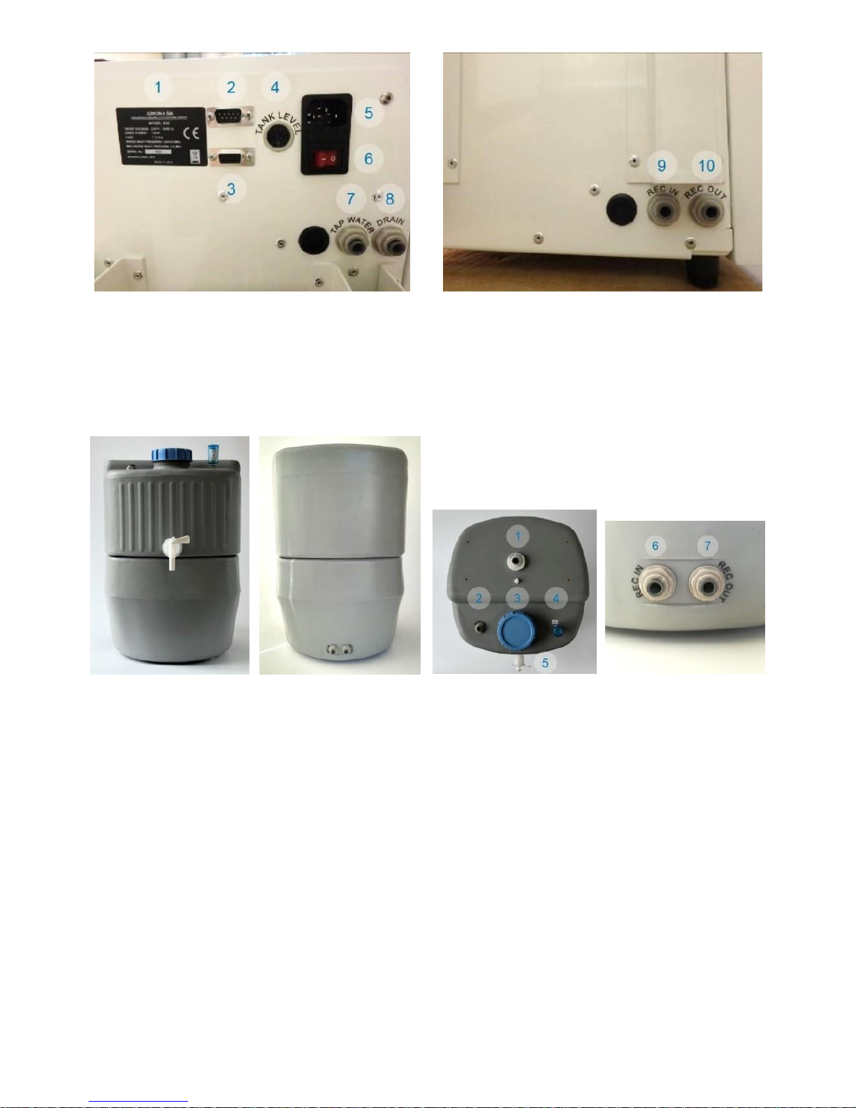
Figure 9. Rear panel.
1. Unit info and serial number. 2. Operation / service socket. 3. Tank water level sensor socket.
4. Mains cable socket and fuse socket. 5. Power switch. 6. Feedwater inlet fitting. 7. Drain fitting. 8. Recirculating water inlet fitting. 9. Recirculating water outlet fitting.
5.5. Pro tank. Storage tank Pro, 30 L in volume, is equipped with water level sensor and
dispenser tap and is designed for storage and recirculation of clean water.
Front view Rear view Top view Bottom fittings
Figure 10. 30L Pro tank.
1. Tank level sensor socket. 2. Overflow. 3. Lid. 4. Air filter. 5. Dispenser tap. 6. Recirculating
water inlet fitting. 7. Recirculating water outlet fitting.
5.6. Filter and module installaton. Open the side door (fig. 1/5) and install cleaning mod-
ules in the following order:
- Deionization module – in the sockets on figure 8/1.
- Polishing module – in the sockets on figure 8/2.
- Pre-filters – in two sockets on figure 8/3.
5.6.1. Deionization and polishing module installation. Processes are identical for both modules.
5.6.1.1 Distinguish the modules (figure 11): deionization module is marked with a blue
sticker, polishing module – with a silver sticker on the front sides.

14
Figure 11. Polishing and deionization modules.
5.6.1.2 Remove both black corks from the module top.
Note. Use the tool for tube detaching (figure 5, right) included in the stand-
ard set, for easier operation.
Press down the small rubber ring on the fitting with fingers (fig. 12/a) or with the tool
(fig. 12/b) and remove the cork.
a b
Figure 12. Removing the cork.
5.6.1.3 Prepare two straight angle module connecting fittings (fig. 13/a) and insert them in
the module fittings to the stop, so that the free ends are rotated towards the side of
the module with guide rail (fig. 13/b). Check the connecting fittings for a tight fit.
a b
Figure 13. Installing the connectors.

15
5.6.1.4 Insert the guide rail in the slot (fig. 14/a). Push both connectors into the fittings on the
unit (fig. 14/b) to the stop. Check the connecting fittings for a tight fit.
a b
Figure 14. Fitting the module inside the unit.
5.6.1.5 Repeat the operation with the second module.
5.6.2. Pre-filter cartridge installation. Turn and remove the protective cap from both of the
cartridges (fig. 15/a). Insert a cartridge in the socket (fig. 1/3 and 15/b) and lock it in
place by turning cartridge a quarter turn to the right ( fig. 15/c) Check the cartridge for
a tight fit. Repeat the operation with the second cartridge.
a b c
Figure 15. Pre-filter installation.
5.6.3. Installed filters and modules look as on figure 8, on the right.
5.7. Tube and sensor installation.
5.7.1. Connect the ½" NPTF to ¼" JG adapter (fig. 16) to one of the ¼" OD tube. Connect
the NPTF/JG adapter to feedwater access pipe (section 4. Pre-installation require-
ments), and the open end of the tube to the TAP WATER fitting on the rear panel
(fig. 9/7).

16
Figure 16. NPTF ½" to JG ¼" adapter for feedwater.
5.7.2. Connect another ¼" OD tube to the DRAIN fitting on the rear panel (fig. 9/8). Connect
the open end of the tube to the drain that is prepared according to section 4. Pre-
installation requirements.
5.8. Connecting the storage tank to the system. Position the tank on an even horizontal
surface (see 4.6).
5.8.1. Connect the REC IN fitting on the rear panel of the unit (fig. 9/9) and the REC OUT
fitting on the rear panel of the tank (fig. 10/7) using a ¼" OD tube.
5.8.2. Connect the REC OUT fitting on the rear panel of the unit (fig. 9/10) and the REC IN
fitting on the rear panel of the tank (fig. 10/6) using the remaining ¼" OD tube.
5.8.3. Connect the ⅜" OD tube with straight angle fitting (fig. 17/a) to the OVERFLOW fitting
on the top side of the tank (fig. 10/2 & 17/b). Connect the open end of the tube to the
drain that is prepared according to section 4. Pre-installation requirements.
a b
Figure 17. Overflow
5.8.4. Connect the water level sensor cable (fig 18/a) to the socket on the tank (fig. 18/b &
10/1) and to the socket on the unit (fig. 18/c & 9/4).
a b c
Figure 18. Water level data cable

17
5.9. Installation of dispenser filter.
5.9.1. For Trace and HPLC models. Unpack the 0.22 μm dispenser filter (fig. 19/a) and the
black sealing ring (fig. 19/b). Screw the filter in the slot below the display so that the
ring stays on top of the thread of the filter (fig. 19/c) in the slot as shown on figure
19/d. White bell cap must cover the dispenser at all times when the water is not being
dispensed.
a b
c d
Figure 19. 0.22 μfilter dispenser installation.

18
5.9.2. For Bio model. Unpack the dispenser ultrafilter (fig. 20/a) and the yellow sealing ring
(fig. 20/b). Screw the filter in the slot below the display so that the ring stays on top
of the thread of the filter (fig. 20/c) in the slot as shown on figure 20/d. Blue bell cap
must cover the dispenser at all times when the water is not being dispensed.
a b
c d
Figure 20. Ultrafilter dispenser installation.
5.10. Insert the black operations dongle (fig. 32) into the socket on the rear panel of the
unit (fig. 9/3).
5.11. Insert the power cable into the socket on the rear panel of the unit(fig. 9/5) and position it for an unobstructed access to cable and the plug.

19
6. Operation
6.1. Open feedwater access (see 4.4).
6.2. Check the power cable for damages and connect the plug to a grounded mains
socket. Turn the power switch (fig. 9/6) to I (on).
6.3. After several second of loading, the display shows (figure 21):
Water quality and grade (fig. 21/6);
Stage of the operation (fig. 21/7);
Total Organic Carbon, or TOC, content (fig. 21/5);
Temperature of the water (fig. 21/8);
Status of the unit (fig. 21/11);
Dispense status;
Volumetric dispense setting;
Tank level.
Figure 21. Control panel and display
6.4. Lowering and controlling TOC (only for HPLC and Bio models). To lower the total
organic carbon (TOC) content, previously purified water passes through organics
photooxidation module and a polishing module to remove resulting products. To
maintain a low TOC level, we recommend constant water recirculation in the storage
tank. TOC level measurements are performed during recirculation stage, and the values are displayed after the unit at least partially fills the tank and performs at least
one recirculation cycle , and the unit is at Filling, Grade I water dispensing or Recirculation stages (fig. 21/7).
6.5. Checking water quality. Press the Mode key (fig. 21/3) to check the water quality.
Unit changes the stage (fig. 21/7) and quality values appear (fig. 21/6).
6.5.1. Diagnostic screen (figure 22). Press the Mode key twice in quick succession. Display
will show the diagnostic screen that provide information and status for all sensors and
components, as well as the tank water level.

20
Figure 22. Diagnostics mode.
1. Dispensing volume. 2. Grade I water quality. 3. TOC monitor (HPLC & Bio). 4. Polishing module status. 5. Water level in storage tank. 6. Pre-filter countdown. 7. Grade II water quality. 8.
Deionization module status.
6.6. Unit rinsing. A rinsing is neccessary before starting the operation. Press the Run
key (fig. 21/1) to start the rinsing cycle. Leave the unit rinsing for 2 hours.
Attention! Check the fittings inside the unit for leakage.
Check the water flow in the REC OUT tube abd drain tube. The water flow in the drain
tube must be 2–5 times stronger than in the REC OUT tube. If the REC OUT tube
flow is dtronger, then the RO membrane is damaged. Stop the unit by pressing the
Run key and contact the service.
6.7. Filling the tank. Press and hold the Run key for 2 seconds. If the tank is connected
and not full and the feedwater supplying pressure is adequate, display shows the
Filling tank stage change. Unit fills the storage tank with Grade II water. As soon as
the tank is full, unit shuts off the water supply and displays the Tank Full message.
This takes approximately 1 hour with an empty tank.
6.8. Recirculation (models HPLC and Bio only). Allow the unit to fill the storage tank,
disconnect water supply and setup the recirculation schedule as shown below. Leave
the unit recirculating for 8 hours. Recirculation removes all remaining organic contamination and lowers the TOC levels below 2 ppb.
Attention! Microfilter / ultrafilter must be rinsed before use! When the tank is full,
press the Dispense key (fig. 21/4) and let flow at least 10 L of purified
water through the filter.
6.9. Menu of the unit (figure 23). Additional settings for the unit are available by pressing
the Menu key (fig. 21/2). To navigate the menu, use arrow keys (fig. 21/9), to select
an item, press the ОК key (fig. 21/10), to return to the previous level or to exit the
menu – the Menu key.
6.9.1. Volumetric Dispense (figure 24). This menu item controls turning on the volumetric
dispense and setting the dispensed water volume by pressing the Dispense key (fig.
21/4). Select the set dispense volume (0.01 to 10 L, with 0.01 L increment) using the
up and down arrow keys. To change the next digit, press the Mode key (fig. 21/3).
To confirm the changes, press the ОК key.

21
Note. You can set the volume by teaching the unit directly. Before dispens-
ing, press the up arrow key (fig. 21/9). Parameter Volumetric changes
to Teach on a red background on display (figure 25). Dispense the
neccessary volume (see 6.10). Unit remembers the dispensed volume and uses it for the next dispensing.
6.9.2. Parameters (figure 26). Unit parameters setup: measurement units, setting date and
time, recirculation schedule.
6.9.2.1 Measurement units (figure 27). Choose between μS / cm или MOhm * cm.
6.9.2.2 Set time and date (figure 28). Use the up and down arrows, Mode and ОК keys to
set the time and date digit by digit.
6.9.2.3 Recirculation (figure 29). Setup the recirculation schedule. First, the Recirculation period (figure 30): every 10, 25 or 50 minutes. Then, the Recirculation time (figure 31):
10, 14 or constantly (i.e. time equals period).
6.9.3. Sensors. Current menu item allows checking the sensors of the unit and sending the
log to PC. Accessible only by service engineers.
6.9.4. Maintenance. Current menu item allows resetting the pre-filter timer, removing the
alarm notifications, recalibrating dispenser, resetting to factory settings and checking
the firmware version. Accessible only by service engineers.
Figure 23. Figure 24.
Figure 25. Figure 26.

22
Figure 27. Figure 28.
Figure 29. Figure 30.
Figure 31.
6.10. Dispensing Grade I water. After rinsing (see 6.6) and filling the tank (see 6.7), remove
the bell cap and place the vessel for purified water. Press the Dispense key (fig.
21/4). Unit performs a 5 to 10 s internal rinsing and starts dispensing purified water.
Note. If the ultrafilter is installed, loosen the degassing valve (fig. 20/1), to
remove the air bubbles.
Press the Dispense key again to stop the water dispensing. If the volumetric dis-
pense is set (see 6.9.1), then dispensing stops after set volume (fig. 21/11, Volumetric).
6.11. Dispensing Grade II water. When the storage tank is filled, place the vessel for clean
water under the tap (fig. 10/5) on the storage tank.
6.12. Shutdown. If the recirculation is not scheduled, shut down the unit. Put the unit in
the OFF stage by pressing the Run key. Turn the power switch (fig. 9/6) into position
О (off). Disconnect the mains plug from the socket. Shut off the feedwater access
pipe.

23
7. Specifications
The unit is designed for operation in closed laboratory rooms at ambient temperature
from +15°C to +30°C (59 to 86 °F) in a non-condensing atmosphere and relative humidity
between 20% and 80%.
Biosan is committed to a continuous programme of improvement and reserves the
right to alter design and specifications of the equipment without additional notice.
7.1. Purified water specification
Water conductivity
Grade I .................................................................................................0.055 μS / cm
Grade II .............................................................................................. < 0.1 μS / cm
Grade I water resistivity ................................................................... 18.2 MOhm * cm
TOC................................................................................................................ < 2 ppb
RNase (Labaqua Bio) .......................................................................... < 0.01 ng / mL
DNase (Labaqua Bio) ............................................................................... < 4 pg / mL
Bacteria ................................................................................................ < 1 CFU / mL
Endotoxins
Labaqua HPLC ................................................................................... < 0.15 EU / mL
Labaqua Bio ..................................................................................... < 0.001 EU / mL
Particles larger than 0.22 μm ........................................................................ < 1 / mL
Nominal water flow
Grade II ............................................................................................................ 10 L/h
Dispenser water flow
Grade I ........................................................................................................... 4 L/min
Grade II .......................................................................................................... 2 L/min
Deionization module lifetime (standard) ............................................................. 1 m3
Regeneration .................................................................................................. > 30 %
7.2. General specifications
Dimensions ................................................................................... 320x560x620 mm
Weight1, empty / operating unit
Labaqua Trace ........................................................................................... 24 / 27 kg
Labaqua HPLC ........................................................................................... 25 / 28 kg
Labaqua Trace ........................................................................................... 26 / 29 kg
Storage tank volume .......................................................................................... 30 L
Noise level, 1 m from the unit ................................................................. below 47 dB
Input current / Power consumption ....................... AC 200–240 V, 50–60 Hz / 130 W
Fuse .......................................................................................................... 220 V, 3 A
Feedwater pressure ..................................................................................0.5 – 5 bar
Feedwater conductivity........................................................................ < 900 μS / cm
Feedwater access connection ............................................................... Ø 1/2" NPTF
1
Accurate within ±10%

24
Table 3. Replacement parts
Description
Catalogue number
Suspended 1 μm particle filter, carbon
BS-070104-KK
Suspended 1 μm particle filter, polyphosphate/carbon
BS-070104-LK
Replacement pre-filter cartridge set
BS-070104-AK
Replacement deionization module
BS-070104-IK
Replacement polishing module
BS-070104-BK
Replacement UV-lamp for sterilization
BS-070104-CK
Replacement UV-lamp for photooxidation
BS-070104-DK
Replacement 0.22 μm microfilter
BS-070104-GK
Replacement ultrafilter (only for model Bio)
BS-070104-FK
8. Troubleshooting
Table 4. Troubleshooting
Problem
Solution
Switching from Filling Tank
stage mode to Low Pressure
and back
Replace pre-filters (fig. 15)
Check the feedwater pressure. Required pressure is 0.5
bar or higher
Low Pressure stage mode
Replace pre-filters (fig. 15)
Replace feedwater access pipe suspended particle fil-
ters (fig. 4) or contact Biosan for a solution
Check if solenoid valve is in order, contact Biosan for a
solution
Error 1
Replace deionization module (fig. 11)
Error 2
Replace polishing module (fig. 11)
Error 5
Replace pre-filters (fig. 15)
Conductivity value is "...."
Conductivity sensor is empty (not filled with water)
Check the operation dongle (see 5.10)
Water quality is below 10 μm
Conductivity value is in the 1.0–
1.5 μS/cm range and does not
change
Validation dongle is connected. Replace with the opera-
tion dongle (see 5.10)
Resistivity value is in the 0.6–
0.9 MOhm*cm range and does
not change
Temperature value is "--.-"
Temperature sensor is not connected or damaged
TOC value is "---"
TOC has not been measured yet. Wait until at least one
recirculation cycle completes (approximately 1 hour)
Sound signal during Filling Tank
stage
Replace UV sterilization lamp, contact Biosan for a so-
lution

25
9. Care and maintenance
9.1. If the unit requires maintenance, disconnect the unit from the mains and contact Biosan or your local Biosan representative.
9.2. All maintenance and repair operations must be performed only by qualified and specially trained personnel.
9.3. Cleaning and disinfection. Use a moist clean soft cloth to wipe the outer surfaces of
the unit.
9.4. Dongles for the unit.
Operating dongle Validation dongle
Figure 32. Dongles for the unit
9.5. Service schedule. Use only the components recommended by the manufacturer. Replace components according to the table below:
Table 5. Component replacement period
Replacement part
Replacement period
Note
Pre-filter cartridges
When the filters are clogged or every 6
months. Replace both simultaneously.
Stage changes be-
tween Filling tank and
Low pressure
Deionization module
On Error 1 or when Grade II conductivity
exceeds 0.5 μS/cm
Polishing module
On Error 2 or when Grade I conductivity ex-
ceeds 0.1 μS/cm
Depends on water us-
age
Sterilization UV
lamp
As required (every 2 years on average)
For model Bio
Oxidation UV lamp
For models HPLC & Bio
0.22 μm filter dis-
penser
Every 3–6 months
For models Trace &
HPLC
Ultrafilter
Every 6–12 months
For model Bio
9.6. Filter and module replacement.
9.6.1. Microfilter and ultrafilter dispensers. Put the unit in the OFF stage by pressing the
Run key and unscrew the filter. Replace with a new one according to 5.9.
9.6.2. Pre-filter cartridges.
- Put the unit in the OFF stage by pressing the Run key;
- Open the side door;
- Remove the old filters by turning them to the left for a quarter turn, then by pulling
down;
- Replace with a new set according to 5.6.2.
Note. Replace both cartridges at the same time.

26
9.6.3. Polishing module. To replace, use the tool on figure 5.
- Put the unit in the OFF stage by pressing the Run key;
- Open the side door;
- Insert the tool under the right angle fitting (fig. 33/a) and press down (fig. 33/b);
- Rotate the fittings inside fig. (33/c) and remove the old module;
- Replace with a new one according to 5.6.1.
9.6.4. Deionization module. Replacement is identical to polishing module replacement. Temorarily remove the pre-filter cartridges (see 9.6.1).
a b c
Figure 33. Polishing and deionization module replacement.
9.7. Emptying the tank.
- Drain all available water from the tank by tap (fig. 10/5);
- Remove the tube from the REC IN fitting on the rear panel of the unit (fig. 9/9) and
drain the remaining water. Reattach the tube.
9.8. Recirculator disinfection.
- Fill the tank (see 6.7) or use a partially filled tank with a disconnected level sensor
(fig. 18);
- Put the unit in the StandBy stage by pressing the Run key;
- Remove the polishing module (see 9.6.3);
- Connect the module fittings in the unit with a bypass tube (fig. 34);
Figure 34. Inserted bypass tube.

27
- Remove the storage tank lid (fig. 10/3) and add hydrogen peroxide solution to the
tank so that the finac concentration would be approximately 1% by volume;
Caution! 30% hydrogen peroxide solution can damage polypropylene compo-
nents. Use appropriate containers and protective equipment when
working with unsafe liquids.
- Put the unit in the Recirculate stage by pressing the Run key;
- Setup the recirculation period to 10 minutes, recirculation time to 5 minutes (see
6.9.2.3);
- Allow the unit to recirculate for 4–6 hours;
- Remove the microfilter or ultrafilter (fig. 19 & 20) and the water level sensor cable
(fig. 18). Dispense approximately half of the solution;
- Connect the water level sensor cable and fill the tank;
- Remove the water level sensor cable and allow the unit to recirculate for approxi-
mately 1 hour;
- Dispense all water and repeat two previous steps;
- Dispense all water and put the unit in the StandBy stage by pressing the Run key;
- Remove (with the tool from figure 5) the bypass tube;
- Replace the polishing module, and microfilter or ultrafilter. Procedure is complete.

28
10. Warranty
10.1. The Manufacturer guarantees the compliance of the unit with the requirements of
Specifications, provided the Customer follows the operation, storage and transportation instructions.
10.2. The warranted service life of the unit from the date of its delivery to the Customer is
24 months. For extended warranty, see 8.5.
10.3. Warranty covers only the units transported in the original package.
10.4. If any manufacturing defects are discovered by the Customer, an unsatisfactory
equipment report shall be compiled, certified and sent to the local distributor address.
To obtain the claim form, visit section Technical support on our website at link below.
10.5. Extended warranty. Contact your local Biosan representative or our service department through the Technical support section on our website at the link below.
Technical support
biosan.lv/en/support
10.6. The following information will be required in the event that warranty or post-warranty
service comes necessary. Complete the table below and retain for your records.
Model
Labaqua Trace / Labaqua HPLC / Labaqua Bio,
Water purification system
Serial number
Date of sale

29
11. EU Declaration of conformity
Unit type Water purification system
Models Labaqua Trace, Labaqua HPLC, Labaqua Bio
Serial number 14 digits styled XXXXXXYYMMZZZZ, where XXXXXX is
model code, YY and MM – year and month of production,
ZZZZ – unit number.
Manufacturer SIA BIOSAN
Latvia, LV-1067, Riga, Ratsupites str. 7/2
Applicable Directives EMC Directive 2014/30/EU
LVD Directive 2014/35/EU
RoHS2 2011/65/EU
WEEE 2012/19/EU
Applicable Standards LVS EN 61326-1: 2013
Electrical equipment for measurement, control and
laboratory use. EMC requirements. General requirements.
LVS EN 61010-1: 2011
Safety requirements for electrical equipment for
measurement, control, and laboratory use. General
requirements.
We declare that this product conforms to the requirements of the above Directives
____________________ ____________________
Signature Signature
Svetlana Bankovska Aleksey Miroshnik
Managing director Head of QA department
____________________ ____________________
Date Date

Biosan SIA
Ratsupites 7, build.2, Riga, LV-1067, Latvia
Phone: +371 67426137 Fax: +371 67428101
http://www.biosan.lv
Edition 1.01 – September 2018
 Loading...