

Page 1

Smart-Max
Multi-functional platform
Operator’s Manual
Page 2

Smart-Max
Multi-functional platform
Operator's Manual
OM - 2320
Date of release: 13 December 2013
OM – 2320 – 00 – 00
Page 3

TABLE OF CONTENTS
1. Preface ....................................................................................... 1
2. Smart-Max main unit ................................................................. 9
3. Smart-Max menus .................................................................... 13
4. Cryo-SC protocol ..................................................................... 23
5. Maintenance ............................................................................. 33
6. Contacts ................................................................................... 35
OM – 2320 – 00 – 00
Page 4

OM – 2320 – 00 – 00
Page 5

1. Preface
1.1 Introduction to the Smart-Max device and its features
The Smart-Max uses a thermal plate for controlled cooling and heating of blood,
blood derivatives or cellular products.
The Smart-Max allows mixing of product bags by means of compressed air inside
polyurethane cuff bags.
The device can inject biological products inside product bags by means of two
peristaltic pumps.
The Smart-Max device consists of:
• Cooling/heating plate
• Universal mixing device
• Injection device
1.2 Indication for use
The Smart-Max device is intended for use in the processing of blood, blood
derivatives or cellular products in order to cryo-prepare, thaw, incubate or inject
biological products for medical purpose.
The Smart-Max device is intended for the safe and reproducible mixing of bag(s)
under regulated temperature (cooling or heating) and / or injection of biological
additives into the bag at a controlled rate.
1.3 Manufacturer
Biosafe SA is an ISO 9001 / ISO 13485 certified company, working under a number
of national and regional directives.
1.3.1 Address
Biosafe SA • Route du Petit-Eysins 1 • 1262 Eysins • Switzerland
Telephone: +41 22 365 27 27 • Fax: +41 22 365 27 37
www.biosafe.ch • info@biosafe.ch
Biosafe America, Inc. • 1225 North Loop West, Suite 120 • Houston, TX 77008 • USA
Telephone: +1 713 936 26 15 • Fax: +1 713 456 27 66
www.biosafeamerica.com • info@biosafeamerica.com
Biosafe Asia-Pacific Ltd. • Room 3012, 30/F, Tower 1, The Gateway, 25 Canton
Road • Tsim Sha Tsui, Kowloon • Hong Kong
Telephone: +852 2956 7500
www.biosafeasiapacific.com • info@biosafeasiapacific.com
Biosafe Medical Device International Trading (Shanghai) Co. Ltd. • Rm 80, 38F, Park
Place No.1601 Nanjing West Road • Shanghai 200040 • China
Telephone: +86 21 61373214 • Fax: +86 21 61373210
www.biosafechina.com • info@biosafechina.com
Preface OM – 2320 – 01 – 00 1
Page 6

1.4 How to use this manual
This operating manual is organized in functional sections to provide easy access to
information concerning the Smart-Max device.
Prior to using the Smart-Max device, this manual should be read in its entirety.
The Table of Contents can be used to locate specific information.
1.4.1 Proprietary clause
The content of this manual is the exclusive property of Biosafe SA.
It is strictly forbidden to reproduce and/or disseminate any of the contents without the
prior written permission of Biosafe SA.
1.5 Warnings and Precautions
1.5.1 General
To ensure safe and effective use of the Smart-Max, operation should only be
entrusted to trained personnel.
The Smart-Max equipment has not been designed for any modification by the enduser or third party.
Intervention such as modification, revision, maintenance or repair should only be
performed by approved Biosafe technicians.
Unauthorized intervention performed by the user may result in
incorrect operation of the system.
Prior to using any part of the Smart-Max, the operator should read all instructions in
this manual.
In addition, the operator must check that the equipment functions safely and ensure
proper working conditions prior to use.
A Biosafe representative should be contacted if any doubt exists concerning the use
of the Smart-Max device.
Biosafe is not liable for any injury or damage resulting from use of the Smart-Max
device that does not conform to the indications in this Operator’s Manual.
Biosafe cannot be held responsible for the quality and subsequent effects of products
processed on the Smart-Max that have undergone subsequent post-processing.
1.5.3 Blood manipulations
If blood spillage or leakage occurs, the product should be discarded (see Chapter 6
for cleaning procedures).
Gloves and protective clothing should be worn for all blood handling operations.
1.5.4 Electro-Magnetic Compatibility
Recommendations as required by IEC 60601-1-2 §6.8.2.201
Medical Electrical Equipment needs special precautions regarding EMC and needs to
be installed and put into service according to the EMC information provided in this
Preface OM – 2320 – 01 – 00 2
Page 7
accompanying document. Portable and mobile RF communications equipment can
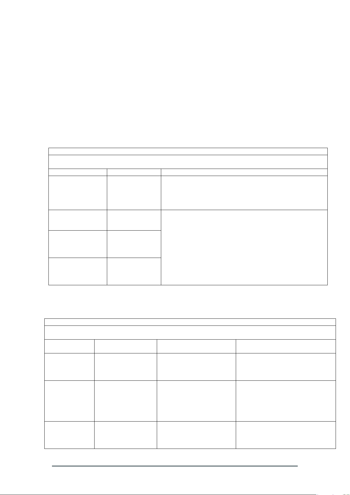
Guidance and manufacturer’s declaration – electromagnetic emission
The Smart-Max is intended for use in the electromagnetic environment specified below. The customer or
the user of the Smart-Max should assure that it is used in such an environment.
Emissions test
Compliance
Electromagnetic environment - guidance
RF emissions
CISPR 11
Group 1
The Smart-Max uses RF energy only for its internal function.
Therefore, its RF emissions are very low and are not likely to
cause any interference in nearby electronic equipment.
RF emissions
CISPR 11
Class A
The Smart-Max is suitable for use in all establishments other
than domestic and those directly connected to the publicvoltage power supply network that supplies buildings used for
domestic purposes.
Harmonic emissions
IEC 61000-3-2
Class A
Voltage fluctuations
/
flicker emissions
IEC 61000-3-3
Complies
Guidance and manufacturer´s declaration – electromagnetic immunity
The Smart-Max is intended for use in the electromagnetic environment specified below. The user of the SmartMax should assure that it is used in such an environment.
Immunity test
IEC 60601
test level
Compliance level
Electromagnetic environment -
guidance
Electrostatic
discharge (ESD)
IEC 61000-4-2
± 6 kV contact
± 8 kV air
± 6 kV contact
± 8 kV air
Floors should be wood, concrete or
ceramic tile. If floors are covered
with synthetic material, the relative
humidity should be at least 30 %.
Electrical fast
transient / burst
IEC 61000-4-4
± 2 kV for power
supply lines
± 1 kV for input/output
lines
± 2 kV for power
supply lines
± 1 kV for input/output
lines
Main power quality should be that of
a typical commercial or hospital
environment.
Surge
IEC 61000-4-5
± 1 kV differential
mode
± 2 kV common mode
± 1 kV differential
mode
± 2 kV common mode
Main power quality should be that of
a typical commercial or hospital
environment.
affect Medical Electrical Equipment.
All staff involved must receive an explanation of the ESD warning symbol and
training in ESD precautionary procedures, and that the users hand should be
discharged by earth bonding (Refer to 1.8 Symbol chart and abbreviations).
The Smart-Max should not be used adjacent to or stacked with other equipment. If
adjacent or stacked use is necessary, the Smart-Max should be observed to verify
normal operation in the configuration in which it will be used. Tables below help to
determine such conditions.
Table 201 – Guidance and manufacturer´s declaration – electromagnetic
emission – for all EQUIPMENT AND SYSTEMS (see 6.8.3.201 a) 3))
Table 202 – Guidance and manufacturer's declaration – electromagnetic
immunity – for all EQUIPMENT and SYSTEMS (see 6.8.3.201 a) 6))
Preface OM – 2320 – 01 – 00 3
Page 8

Voltage dips,
short
interruptions and
voltage variations
on power supply
input lines
IEC 61000-4-11
< 5 % UT
(>95 % dip in UT )
for 0,5 cycle
40 % UT
(60 % dip in UT )
for 5 cycles
70 % UT
(30 % dip in UT )
for 25 cycles
95 % UT
(5 % dip in UT )
for 5 seconds
< 5 % UT
(>95 % dip in UT )
for 0,5 cycle
40 % UT
(60 % dip in UT )
for 5 cycles
70 % UT
(30 % dip in UT )
for 25 cycles for 115V only
95 % UT
(5 % dip in UT )
for 5 seconds
Main power quality should be that of
a typical commercial or hospital
environment. If the user of the
Smart-Max requires continued
operation during power interruptions,
it is recommended that the SmartMax be powered from an
uninterruptible power supply or a
battery.
Power frequency
(50/60 Hz)
magnetic field
IEC 61000-4-8
3 A/m
30 A/m
Power frequency magnetic fields
should be at levels characteristic of
a typical commercial or hospital
environment.
NOTE UT is the a. c. mains voltage prior to application of the test level.
Preface OM – 2320 – 01 – 00 4
Page 9
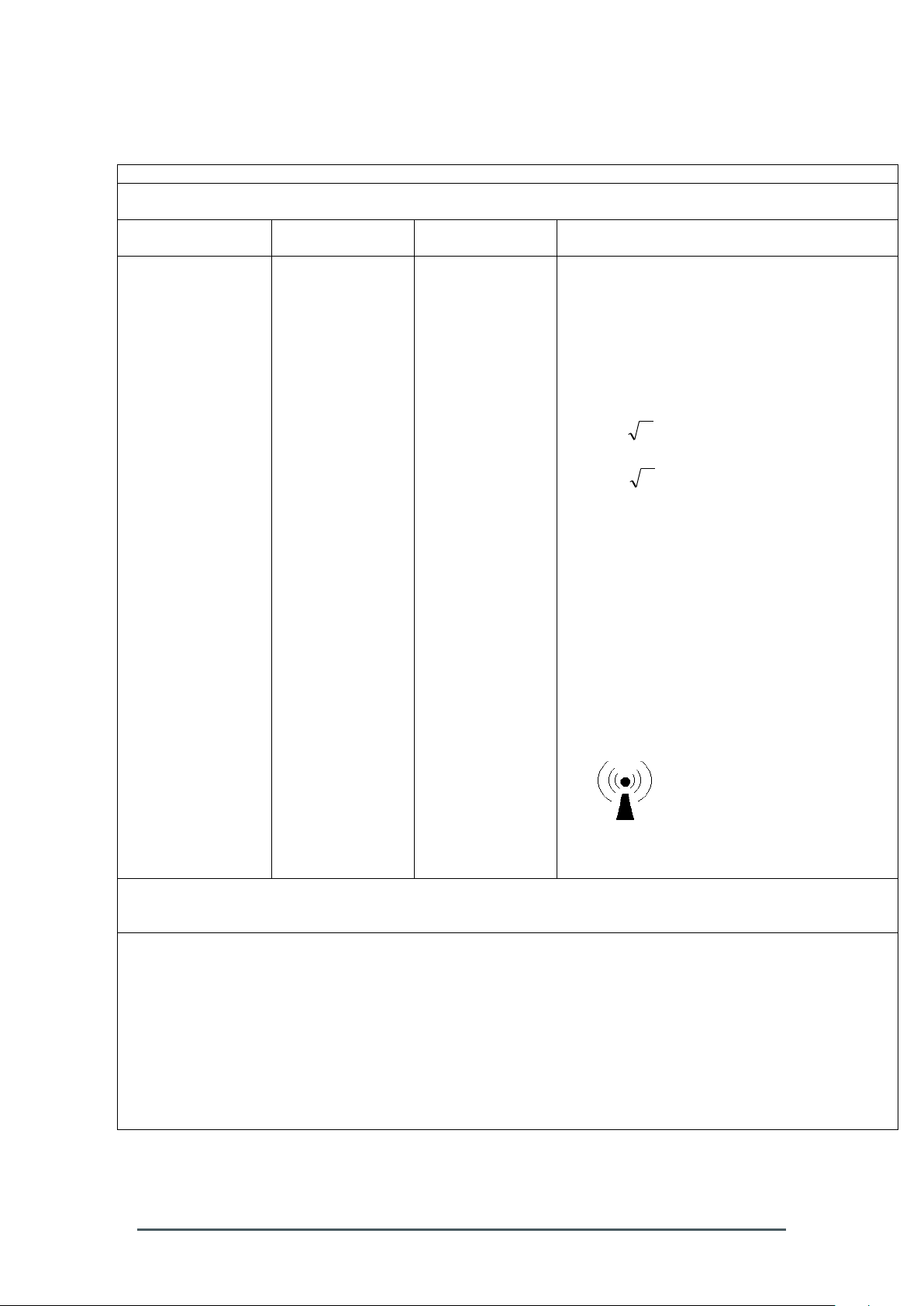
Table 204 – Guidance and manufacturer´s declaration – electromagnetic
Guidance and manufacturer´s declaration – electromagnetic immunity
The Smart-Max is intended for use in the electromagnetic environment specified below. The customer or the
user of the Smart-Max should assure that it is used in such an environment.
Immunity test
IEC 60601 test
level
Compliance level
Electromagnetic environment - guidance
Conducted RF
IEC 61000-4-6
Radiated RF
IEC 61000-4-3
3 Vrms
150 kHz to 80 MHz
3 V/m
80 MHz to 2,5 GHz
3 Vrms
3 V/m
Portable and mobile RF communications
equipment should be used no closer to any part
of the Smart-Max, including cables, than the
recommended separation distance calculated
from the equation applicable to the frequency of
the transmitter.
Recommended separation distance
Pd 2.1
80 MHz to 800 MHz
Pd 3.2
800 MHz to 2,5 GHz
where p is the maximum output power rating of
the transmitter in watts (W) according to the
transmitter manufacturer and d is the
recommended separation distance in meters
(m).a
Field strengths from fixed RF transmitters, as
determined by an electromagnetic site survey,
should be less than the compliance level in
each frequency range.b
Interference may occur in the vicinity of
equipment marked with the following symbol:
NOTE 1 At 80 MHz and 800 MHz, the higher frequency range applies.
NOTE 2 These guidelines may not apply in all situations. Electromagnetic is affected by absorption and
reflection from structures, objects and people.
a
Field strength from fixed transmitters, such as base stations for radio (cellular/cordless) telephones and
land mobile radios, amateur radio, AM and FM radio broadcast and TV broadcast cannot be predicted
theoretically with accuracy. To assess the electromagnetic environment due to fixed RF transmitters, an
electromagnetic site survey should be considered. If the measured field strength in the location in which the
Smart-Max is used exceeds the applicable RF compliance level above, the Smart-Max should be observed to
verify normal operation. If abnormal performance is observed, additional measures may be necessary, such as
reorienting or relocating the Smart-Max.
b
Over the frequency range 150 kHz to 80 MHz, field strengths should be less than 3 V/m.
immunity – for EQUIPMENT and SYSTEM that are not LIFE-SUPPORTING (see
6.8.3.201 b))
Table 206 – Recommended separation distances between portable and mobile
Preface OM – 2320 – 01 – 00 5
RF communications equipment and the EQUIPMENT or SYSTEM -
Page 10
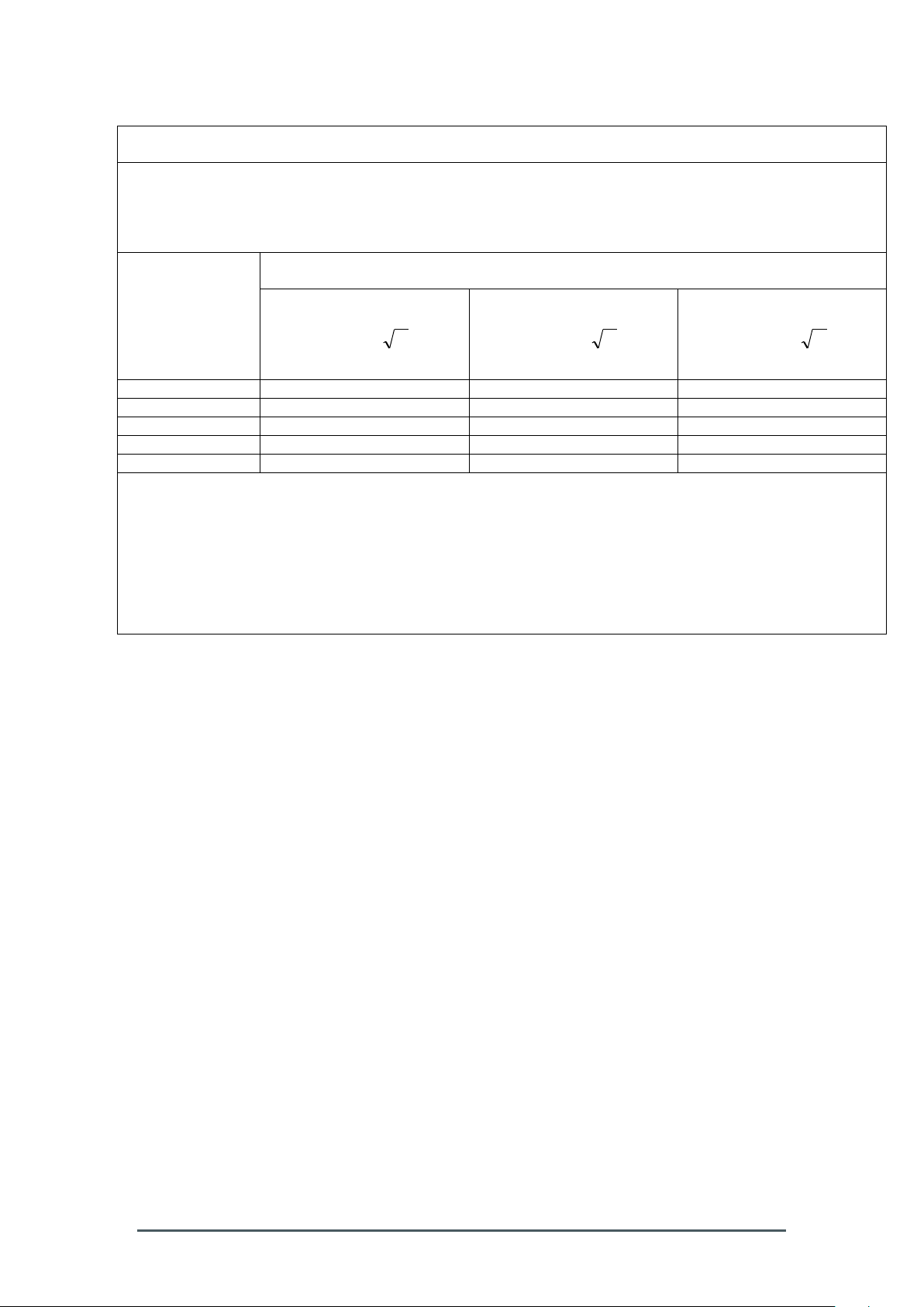
for EQUIPMENT and SYSTEMS that are not LIFE-SUPPORTING (see 6.8.3.201 b))
Recommended separation distances between
portable and mobile RF communications equipment and the Smart-Max device
The Smart-Max is intended for use in an electromagnetic environment in which radiated RF disturbances are
controlled. The customer or the user of the Smart-Max can help prevent electromagnetic interference by
maintaining a minimum distance between portable and mobile RF communications equipment (transmitters)
and the Smart-Max as recommended below, according to the maximum output power of the communications
equipment
Separation distance according to frequency of transmitter
M
Rated maximum
output of
transmitter
W
150 kHz to 80 MHz
Pd 2.1
80 MHz to 800 MHz
Pd 2.1
800 MHz to 2,5 GHz
Pd 3.2
0,01
0.12
0.12
0.23
0,1
0.37
0.37
0.74
1
1.17
1.17
2.33
10
3.69
3.69
7.38
100
11.67
11.67
23.33
For transmitters rated at a maximum output power not listed above, the recommended separation distance d in
meters (m) can be estimated using the equation applicable to the frequency of the transmitter, where P is the
maximum output power rating of the transmitter in watts (W) according to the transmitter manufacturer.
NOTE 1 At 80 MHz and 800 MHz, the separation distance for the higher frequency range applies.
NOTE 2 These guidelines may not apply in all situations. Electromagnetic propagation is affected by
absorption and reflection from structures, objects and people.
1.6 Warranty
Biosafe’s products are designed and manufactured to provide reliable performance
when properly maintained and used in accordance with the instructions provided in
this manual. Each unit is carefully inspected and tested before shipping.
In case of equipment failure or malfunction, Biosafe will replace or repair the
concerned equipment according to the agreement in place.
Equipment failure or malfunction for reasons other than a manufacturing defect (such
as improper handling of the machine or non-compliance with the Operator’s Manual)
is not covered under the Biosafe warranty program and such equipment will be
replaced or repaired at the charge of the end-user.
Biosafe shall under no circumstances be liable for consequential or economical
damage that may be an indirect or direct consequence of a defective part.
1.7 Customer support
All Smart-Max devices are supplied with a copy of the Operator’s Manual.
In addition, competent technical staff will provide end-user training prior to use and
will be available for specific questions or clarifications.
For assistance in technical or application issues, please contact your local
representative or call Biosafe Customer Service in Switzerland + 41 22 365 2705.
Preface OM – 2320 – 01 – 00 6
Page 11
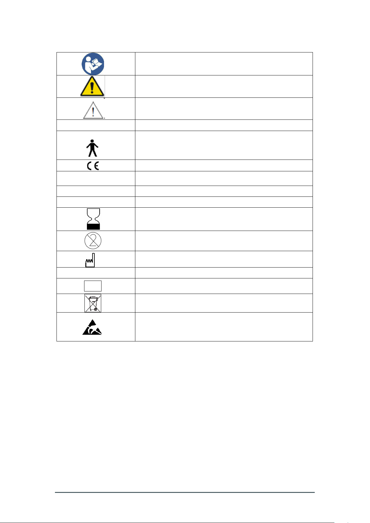
1.8 Symbol chart and abbreviations
Refer to instruction manual/booklet
General warning sign
Caution
Class I
Equipment energized from an external electrical power source
Type B equipment providing a degree of protection against
electrical shocks particularly regarding allowable leakage
current
CE marking of the Smart-Max instrument
~
Alternating current
O
Power off
I
Power on
Expiry date
Not reusable, for single use only.
Date of manufacture
REF
Product number
LOT
Batch designation
Refer to chapter 6.2
Pins of connectors identified with the ESD warning symbol
should not be touched. Connections should not be made to
these connectors unless the user’s hand is discharged by
earth bonding.
Preface OM – 2320 – 01 – 00 7
Page 12

Preface OM – 2320 – 01 – 00 8
Page 13

2. Smart-Max main unit
2.1 General description
The Smart-Max device is intended for the safe and reproducible mixing of bag(s)
under regulated temperature (cooling and heating) and / or injection of biological
additives into the product bag at a controlled rate.
The main features of the Smart-Max are:
USB ports to connect printer, barcode reader, memory stick and other PC
interfaces
LAN, WLAN integration
User selectable multi-language support
Enhanced traceability features (e.g.: procedure report file accessible via USB
key)
Pneumatic mixing with highly flexible pouches
Universal cooling plate for small and large cryobags.
Temperature range involves both cooling and heating between 1°C - 45°C.
2 peristaltic pumps for injection of cryopreservation solution and other
reagents, with the possibility of two parallel injections
Remote access via internet connection
Smart-Max main unit OM – 2320 – 02 – 00 9
Page 14

Mode
Operation
Storage & Transport
Temperature*
+7°C to +27°C
0°C to 45°C
Relative
humidity
30% to 75%, non-condensing
20% to 75%, non-condensing
Maximum
Altitude
2000m, 80 kPa
2000m, 80 kPa
Installation, assembly and modification of the Smart-Max must be done by an approved
Biosafe technician
2.2 Operating and storage requirements
2.2.1 Environmental specifications
The Smart-Max must only be operated under the following environmental conditions:
*The stand-by functioning temperature is +10°C
*Tolerance of the temperature displayed on the screen is +/-1°C
*Tolerance of the injected volume is 5%
The Smart-Max should:
only be operated on a flat, stable, horizontal and clean surface
be used in an open environment to allow sufficient ventilation
be cleaned regularly
be kept upright during transport
be connected to a grounded power supply directly (no adapters or
extension leads)
be installed such that the power switch (located on the back of the machine)
is accessible to power off the device without difficulty
The Smart-Max should not be exposed to:
direct sunlight or strong light sources
liquids or corrosive substances
physical shocks or vibrations
heavy weights
other equipment that contains magnets or generate
magnetic/electromagnetic fields (such as mobile phones)
Smart-Max main unit OM – 2320 – 02 – 00 10
Page 15

8. Peristaltic pumps
5. Bag pole
holder
1. Cover
2. Syringe
holder
3. Closing mechanism
4. Touch screen
6. Pneumatic bags
for mixing
7. Base plate
(small and large bags)
9. Stop button
2.3 Smart-Max Main Processing Unit – Components
Smart-Max main unit OM – 2320 – 02 – 00 11
Page 16

1. Cover
Cover to close or open after bag insertion or removal
2. Syringe holder
Syringe holder adapted for different syringe sizes
3. Closing mechanism
Closing mechanism to lock cover in place
4. Touch screen
Color touch screen
5. Bag pole holder
Support to hang the input, source and other bags. Safe working load is up to 1kg
6. Pneumatic bags for mixing
Pneumatic pouches activated by air pressure
7. Base plate (small and large bags)
Base plate that can accept bags of varying size and volume
8. Peristaltic pumps
Two peristaltic pumps for controlled solution injection
9. Stop button
Stop button to abort a procedure in case of emergency
2.4 Technical specifications of the Smart-Max
Type of protection against electric shock: Class I equipment.
Degree of protection against electric shock: Type B applied part.
For cleaning procedure, please refer to Chapter 6.1
2.4.1 Dimensions (approximate):
Width: 27 cm (10.6”)
Length: 32 cm (12.7”)
Height: 17 cm (6.7”)
2.4.2 Weight:
8.5 kg (18.7 lbs)
2.4.3 Power:
Use only the original certified cable for the power supply.
The Smart-Max equipment should always be connected to an Uninterruptible Power
Supply (UPS).
Input range: 100 to 240 VAC (The Smart-Max automatically adjusts for the
local supply voltage)
Input frequency: 50/60 Hz
Consumption: 250 VA
Smart-Max main unit OM – 2320 – 02 – 00 12
Page 17

3. Smart-Max Menus
To ensure correct usage of the touch screen display, the user should allow a 1
second delay between each touch of the screen.
3.1 Starting Menu
Upon switching on the Smart-Max, an automatic test is performed and the starting
menu is displayed (Fig. 1).
Fig.1
3.2 Smart-Max Menu
3.2.1 Protocol description
Press the protocol icon to display the list of applications available (Fig. 2):
For each application, the respective protocol can then be selected and launched. For
specific instructions on each protocol, please refer to the corresponding chapter
below.
Smart-Max menus OM – 2320 – 03 – 00 13
Page 18

Fig.2
3.2.2 Settings and Data functions
Settings and Data functions can be accessed by pressing the Menu key. The
settings menu includes a service sub-menu which should only be used by Biosafe
service technicians (Fig. 3).
Smart-Max menus OM – 2320 – 03 – 00 14
Page 19

Fig.3
3.2.3 To change language
Select the “Language” icon and choose the appropriate option (Fig. 4).
Fig. 4
3.2.4 Traceability settings
The Smart-Max can be used with a Traceability Kit composed of a printer and a
barcode reader.
This Traceability Kit enables the traceability function for both the procedure and the
protocol. Report files can be printed directly by the printer supplied as part of the
Traceability Kit. Full protocol data (logfiles) can be downloaded to the USB key
provided with the Smart-Max.
Enabling of the traceability option requires a password. Biosafe provides traceability
option passwords to approved operators.
Select “Edit” on the traceability label in order to input or scan text/values (Fig. 5 and
6).
Smart-Max menus OM – 2320 – 03 – 00 15
Page 20

Fig. 5
Fig. 6
Pressing returns the display to the main screen.
Smart-Max menus OM – 2320 – 03 – 00 16
Page 21

3.2.6 Saving data options
In order to save protocol data, select the “Data” icon which allows the displaying of
various reports available at the end of each procedure (Fig. 7).
Fig. 7
The report files contain statistical information on the procedure, including:
• Date and time of processing
• Temperature
• Volume
These values ensure that the process has been performed correctly and that the
product has suffered no extreme conditions.
The logfiles (protocol data) provide more technical information, including:
• Sensors recordings
• Power supply data
These files are used by Biosafe technicians to diagnose the cause of malfunctions.
The report files are pdf files generated from summary files and include a graph of the
procedure.
Once either “Report Files”, “Save Log Files” or “Save Support File” has been chosen
from the Data menu (Fig. 7), a list of files is displayed along with several options. The
files are identified by the time and date they were created (corresponding to the end
of the procedure).
All files can be saved simultaneously, using the “Save all Files” option. Alternatively,
individual files can be saved by selecting them and using “Save selected Files”.
Smart-Max menus OM – 2320 – 03 – 00 17
Page 22

3.3 Protocol Running
The following screen appears when a Smart-Max protocol is running (Fig. 8).
The screen indicates the following:
1. Procedure phase
2. Remaining procedure time (seconds)
3. Added reagent/solution volume into bag(s)
Fig. 8
3.4 Troubleshooting
3.4.1 General
This chapter describes various alarms that can happen during a procedure, and the
actions that need to be taken in such cases.
Warnings and errors are signaled by an alarm.
“Warning” messages allow the procedure to continue once the problem has been
fixed.
“Error” messages do not allow the procedure to continue and will require the
operator to restart it (Fig. 9).
Smart-Max menus OM – 2320 – 03 – 00 18
Page 23

WARNING MESSAGES
WARNING
ID
DESCRIPTION
CORRECTION
COVER_OPENED
9018
Warning for cover
open.
Close the cover and continue
the procedure.
WARN_TEMPERATURE_LOW
9022
Warning
temperature low.
Temperature was detected
by the protocol as low.
Continue the procedure. If
the warning persists, contact
Biosafe support.
WARN_TEMPERATURE_HIGH
9023
Warning
temperature high.
Temperature was detected
by the protocol as high.
Continue the procedure. If
the warning persists, contact
Biosafe support.
Fig. 9
When an “Error” message appears, you are asked to perform the following steps:
1. Read and write down the error message
2. Press to turn off the alarm
When an error occurs, please inform Biosafe service.
3.4.2 Warning messages during the procedure
Smart-Max menus OM – 2320 – 03 – 00 19
Page 24

ERROR MESSAGES
ERROR ID
DESCRIPTION
CORRECTION
TEMP_1_HIGH
TEMP_2_HIGH
TEMP_3_HIGH
TEMP_12_HIGH
10000
10100
10200
10400
The temperature
measured by the
sensors on the
base plate is high.
Switch-off the Smart-Max
device and wait for a few
minutes to let the device cool
down.
Check that air vents are not
obstructed and restart the
Smart-Max.
If the error persists, call
Biosafe support.
TEMP_5_HIGH
10600
The internal
temperature is
high.
TEMP_1_OUT_OF_RANGE
TEMP_2_OUT_OF_RANGE
TEMP_3_OUT_OF_RANGE
11000
11100
11200
Temperature
sensor on the base
plate is not
functioning
properly.
Switch-off the Smart-Max
device and wait for a few
seconds, then restart.
If the error persists, call
Biosafe support.
TEMP_5_OUT_OF_RANGE
11400
Internal
temperature sensor
is not functioning
properly.
PRESSURE_HIGH
PRESSURE_MAXIMUM
COMPRESSOR_POWER_HIGH
PRESSURE_OUT_OF_RANGE
12000
12050
12100
12200
The mixing
mechanism is not
functioning
properly.
Switch-off the Smart-Max
device and wait for a few
seconds, then restart.
If the error persists, call
Biosafe support.
FAN_DISCONNECTED
FAN_SPEED_LOW
13000
13100
The rear fun is not
functioning
properly.
Switch-off the Smart-Max
device and wait for a few
seconds, then restart.
If the error persists, call
Biosafe support.
PELTIER_POWER_CIRCUIT
14000
Temperature
controlling system
not functioning
properly.
Switch-off the Smart-Max
device, wait few seconds and
then restart.
If the error persists, call
Biosafe support.
COVER_OPENED
15000
Cover has been
opened during a
procedure.
Close the cover and restart
the procedure. Ensure to
check and adapt parameters
(see troubleshooting guide
specific for each protocol).
ELEMENT_EXCEPTION
19999
Software error in
hardware element
handling.
Switch-off the Smart-Max
device, wait few seconds and
then restart.
If the error persists, call
Biosafe support.
SOFTWARE_EXCEPTION
20000
Software error
occurred.
Switch-off the Smart-Max
device, wait few seconds and
then restart.
If the error persists, call
Biosafe support.
DEVICE_STOP
10133
STOP key was
pressed.
Validate to restart when
ready.
3.4.3 Error messages during the procedure
Smart-Max menus OM – 2320 – 03 – 00 20
Page 25

PROTOCOL_ABORT
10134
Cancel/abort
button was
pressed.
The user aborted the
procedure. Start the
procedure again.
PROTOCOL_ERROR
10135
An undefined
protocol error
occurred.
A problem with the protocol
was detected. If the problem
persists, contact Biosafe
support.
MICROCONTROLLER_COMM
20100
An error occurred
in the internal
machine
communication
with the
microcontroller
Switch-off the Smart-Max
device, wait few seconds and
then restart. If the error
persists, call Biosafe support.
3.5 Using the Smart-Max
The user must ensure proper working and environmental conditions, and
check that the equipment functions safely prior to usage.
Smart-Max menus OM – 2320 – 03 – 00 21
Page 26

Smart-Max menus OM – 2320 – 03 – 00 22
Page 27

4. Cryo-SC protocol
The user must ensure proper working and environmental conditions, and
check that the equipment functions safely prior to usage.
The Cryo-SC protocol is designed to allow injection of cryoprotectant solution in
volume reduced cord blood with volumes between 10 and 25 ml (before
cryoprotectant solution addition). The Smart-Max device allows a single cord
procedure at a time or two units in parallel.
4.1 Protocol selection
Switch on the Smart-Max AS-310 and wait until the starting menu is displayed. To
prepare bag(s) for the procedure, it is suggested to cool them down to the desired
temperature (e.g. 4°C) with the Smart-Max by using the pre-cooling feature or in a
standard fridge.
In the main menu, select the protocol icon and enter the Cryo-SC protocol by
pressing on the corresponding icon. This selection automatically triggers the cooling
system to begin reaching the desired temperature of 4°C.
Cryo-SC protocol OM – 2320 – 04 – 00 23
Page 28

Leave the Smart-Max cover closed at all times, opening it only to insert or
remove bags. This ensures the device will reach the required temperature in
the fastest time.
Fig. 1
In the protocol menu (Fig. 1), press to select desired bag configuration.
Selection includes solution addition to a single bag, or two bags in parallel.
If only a single small bag is used, ONLY the right side is selectable and bag
must be placed on right side of the plate.
Make your choice by clicking on the appropriate icon (1 or 2 small bags), then select
to return to the general menu of the protocol (Fig. 1).
4.2 Cryobag preparation and installation on Smart-Max
Prepare cryoprotectant solution to be added to volume-reduced cord blood following
your own validated procedure, in a 10 or 20 ml syringe.
The unit head of processing is responsible for choosing and validating the
cryoprotectant solution and quantity to be added for cryopreservation.
Under aseptic conditions, or using a closed kit, connect the syringe containing the
cryoprotectant solution to the FA-100.1 DMSO extension line. The other end of the
FA-100.1 DMSO extension line should be connected to the cryobag containing the
volume reduced cord blood.
Cryo-SC protocol OM – 2320 – 04 – 00 24
Page 29

For specific characteristics of Biosafe’s single-use kits, please refer to the
related Cryopreparation chapter of the Operator’s Manual which describes
connection and preparation of the cryobag for addition of cryopreservation
solution.
Please remember that is necessary to add an extra amount corresponding to
the dead volume of the tubing (1.5 ml) and of applicable, the DMSO filter (1 ml).
Once the FA-100.1 DMSO extension line clamp is opened and primed, open the
cover of Smart-Max and place the cryobag(s) on the platform(s) (Fig. 2). Pay
attention to properly place the tubing between the cryobag and the syringe in the
designated space.
Fig. 2
Check carefully that the bag(s) is in place and close the cover. Ensure proper locking
of the cover by pressing in the black knob placed on the left side (Fig.3).
Fig. 3
Install the syringe containing the cryoprotectant solution in the dedicated support: 10
ml syringes in the small holder, or 20 ml syringes in the large holder (Fig.4).
Fig. 4
Cryo-SC protocol OM – 2320 – 04 – 00 25
Page 30

Install the connector of the FA-100.1 DMSO extension line in the designated holder,
ensuring proper connection (Fig. 4): this will prevent dislodging of syringe containing
cryoprotectant solution during functioning of the peristaltic pump.
Install the tubing of the FA-100.1 DMSO extension line around the circular pump
head, in the direction indicated in Fig. 5. Ensure no kinks or twists of the tubing occur
and then secure tubing around pump by closing the lever of the pump by rotating
forward.
Perform a visual check to ensure installation has properly occurred.
Fig. 5
4.3 Parameter selection
Press button, and the screen will display the protocol’s specific user
selectable parameters (Fig. 6).
Fig. 6
Cryo-SC protocol OM – 2320 – 04 – 00 26
Page 31

Cooling time
Time for cooling the cryobag(s), before starting cryoprotectant solution addition.
Adjustable value between 0 to 20 minutes. If the cryobag(s) has already been cooled
in a fridge, enter 0 to start injection of cryoprotectant solution immediately.
Default value is 10 minutes.
Injection time
Desired time for injecting cryoprotectant solution. Adjustable parameter between 0 to
20 minutes. Recommended value is 12 minutes.
Volume to inject
Volume of cryoprotectant solution to be added to the cryobag(s). Recommended
value is 5 ml.
Once the desired values have been entered, the corresponding flow rate for injection
will be calculated and compared with the device’s limit.
The maximum flow rate possible with the FA-100.1 DMSO extension line is 0.9
ml/min (higher value will not be accepted by the device).
In case of parallel procedures for two cryobags, the same parameters will be
applied to both units. Please install the first unit and keep the cover closed
until the second unit is ready. When the second unit is ready for cryoprotectant
addition, open the cover, install the cryobag, complete the traceability
information, close the cover and launch the automated procedure.
Press the button: if the traceability option is enabled, you’ll be able to insert
the corresponding values; if the traceability option is not enabled, it will start the
automated procedure.
4.4 Traceability function and launching of the automated procedure
If the traceability option of Smart-Max is enabled, the following screen is displayed
(Fig. 7)
Fig. 7
Cryo-SC protocol OM – 2320 – 04 – 00 27
Page 32

Press on , and you can configure the list of ID’s by selecting those that
you want to insert.
When a specific ID is highlighted, enter the corresponding value using the barcode
reader or displayed keyboard, then press .
Ensure proper locking of the cover by pressing in the black knob placed on the left
side (Fig. 3).
In case some of the traceability ID’s have already been inserted, please check the
exactitude of the values, eventually complete the information and start the automated
procedure.
4.5 Starting of the procedure
Press the button, and the screen will display a list of important points to be
verified prior to start of the automated procedure (Fig. 8):
Fig. 8
Ensure all requirements on the list have been verified, and press to begin
the protocol.
During the automated procedure, the display screen reports relevant information for
the procedure (Fig. 9 & 10).
Cryo-SC protocol OM – 2320 – 04 – 00 28
Page 33

Fig. 9
Fig. 10
4.6 Post procedure actions
When the procedure is completed, the following screens are displayed (Fig. 11 & 12):
Before removing the cryobag, remember to close the clamp on the FA-100.1
extension line to avoid unexpected injection of additional solution inside the bag.
Cryo-SC protocol OM – 2320 – 04 – 00 29
Page 34

Fig. 11
Fig. 12
Open the cover by pressing in the black knob on the right side of the cover (Fig. 13),
and remove the bag(s). Opening of the cover will automatically terminate the
procedure and Smart-Max will return to the starting page of the protocol.
Cryo-SC protocol OM – 2320 – 04 – 00 30
Page 35

Fig. 13
Prepare the cryobag(s) for freezing following your own validated procedure.
4.7 Troubleshooting
In case of any error or procedure interruption, a message will appear on the display
(Fig. 14).
Fig. 14
After pressing , the Smart-Max automatically displays the main menu.
For a description of possible errors and corrective actions, please refer to section 3.4
of the Operator’s Manual.
After following the actions reported in the table, you can re-load protocol Cryo-SC to
complete the aborted procedure.
Due to the cord blood unit being in contact with cryoprotectant solution,
troubleshooting actions must be performed as quickly as possible and
validated by the laboratory manager.
Cryo-SC protocol OM – 2320 – 04 – 00 31
Page 36

new Procedure time = new Volume
Initial Volume
Initial time
= 2.5
*
*
12
5
= 6 mins
Before launching the new procedure, all protocol parameters must be checked and
adapted:
Cooling time
In case the interruption occurred during the pre-cooling phase, restart the procedure
and set the parameter at the same value.
In case this phase has already occurred, set the parameter to 0: this will allow
injection to start immediately.
Volume to inject
In case injection of cryoprotectant solution had begun, reduce this value by the
quantity of solution already injected into the cryobag (excluding the volume used for
priming the DMSO extension line).
For example, if the total volume of cryoprotectant in the syringe was 6.5 ml (after
priming) at the start of the procedure, and the syringe contained 4 ml at the moment
of interruption, and the desired volume to inject into the bag is 5ml, the Volume to
add should be set at 5 – (6.5 – 4) = 2.5 ml.
In case the injection of cryoprotectant solution had NOT yet started, set the
parameter at the same value.
Injection time
The value of the parameter must be adapted corresponding to the Volume of
cryoprotectant solution still to be added.
In the previous example Volume to add is now set at 2.5 ml, therefore the new
Procedure time must be set at:
If the parameters have been adapted correctly, the flow rate displayed should be
equal to that of the initial procedure.
Press the button, verify the points listed and the correct installation of the
syringe and the DMSO extension line and then start the automated procedure.
Cryo-SC protocol OM – 2320 – 04 – 00 32
Page 37
5. Maintenance
As with any electrical equipment, fluid entering the Smart-Max can
adversely affect its performance. Do not attempt to clean any internal
parts of the Smart-Max – this should only be done by a Biosafe
approved technician. If in doubt, contact Biosafe for advice.
Any other maintenance or technical intervention should only
be performed by Biosafe approved technicians.
The Smart-Max is designed to require minimal maintenance.
The only maintenance the operator must perform consists of cleaning the outer
surfaces of the Smart-Max and the associated power cables.
The Smart-Max equipment should be serviced every 1000 procedures or, at a
minimum, once per year. The elements that require servicing by the Biosafe
approved technician are described in the Service Manual.
4.1 Cleaning
The Smart-Max should be cleaned on a regular basis or after any incident such as
product leakage.
The following procedure should be used for cleaning:
1. Switch off the Smart-Max before beginning the cleaning procedure to prevent
risk of electrical shock.
2. Rubber gloves and a protective gown should be worn to prevent direct skin
contact with any spilled cord blood during the cleaning procedure.
3. With gauze bandage or a soft paper soaked with warm water clean the blood
off the surface. Dry the damp surface with soft paper and repeat as necessary
to ensure the surface is clean.
4. Use an antibacterial solution to disinfect the surface - such as Meliseptol®.
4.2 Waste management
This product is subject to Directive 2002/96/EC of the European
Parliament and the Council of the European Union on waste electrical
and electronic equipment (WEEE) and, in jurisdictions adopting that
Directive, is marked as being put on the market after August 13, 2005,
and should not be disposed of as unsorted municipal waste. Please
utilize your local WEEE collection facilities in the disposition of this
product and otherwise observe all applicable requirements.
Maintenance OM – 2320 – 05 – 00 33
Page 38

4.3 Warranty
Biosafe products are designed and manufactured to provide reliable, trouble free
performance when properly maintained and used in accordance with the Operator’s
Manual.
Biosafe warrants to the original purchaser that the unit has been fully tested and
delivered according internal Biosafe procedures. Maintenance service and, if
required, repairs are free of charge for one year from the date of shipment.
Equipment failure due to reasons other than manufacturing defects such as
accidents, misuse or failure to perform scheduled maintenance is excluded from
warranty coverage.
Maintenance OM – 2320 – 05 – 00 34
Page 39

6. Contacts
Biosafe SA
Route du Petit-Eysins 1
Telephone: +41 22 365 27 27
1262 Eysins, VD
Fax: +41 22 365 27 37
Switzerland
E-mail: info@biosafe.ch
www.biosafe.ch
Support
Telephone: +41 22 365 27 05
E-mail: support@biosafe.ch
Biosafe America, Inc.
1225 North Loop West
Telephone: +1 713 936 26 15
Suite 120
Fax: +1 713 456 27 66
Houston, TX 77008
E-mail: info@biosafeamerica.com
USA
www.biosafeamerica.com
Support
Telephone: +1 713 936 26 16
E-mail: support@biosafeamerica.com
Biosafe Asia-Pacific Ltd.
Room 3012, 30/F
Telephone: +852 2956 7500
Tower 1, The Gateway
Fax: +852 2956 2110
25 Canton Road
E-mail: info@biosafeasiapacific.com
Tsim Sha Tsui, Kowloon
Hong Kong
www.biosafeasiapacific.com
Support
E-mail: support@biosafeasiapacific.com
Biosafe Medical Device
International Trading (Shanghai)
Co. Ltd
Rm 80, 38F, Park Place No.1601
Telephone: +86 21 61373214
Fax: +86 21 61373210
Nanjing West Road
E-mail: info@biosafechina.com
Shanghai 200040
China
www.biosafechina.com
Support
E-mail: support@biosafechina.com
Biosafe Latin America
Av. Chedid Jafet, 222 – 5th floor
Telephone: +55 11 2655 1731
Fax: +55 11 99326 5454
Block D – Vila Olimpia
E-mail: info@latinamerica.com
04551-065 Sâo Paulo
Brazil
www.biosafelatinamerica.com
Support
E-mail: support@biosafelatinamerica.com
Contacts OM – 2320 – 06 – 00 35
Page 40

Local representative (if applicable)
Contacts OM – 2320 – 06 – 00 36
 Loading...