

Page 1
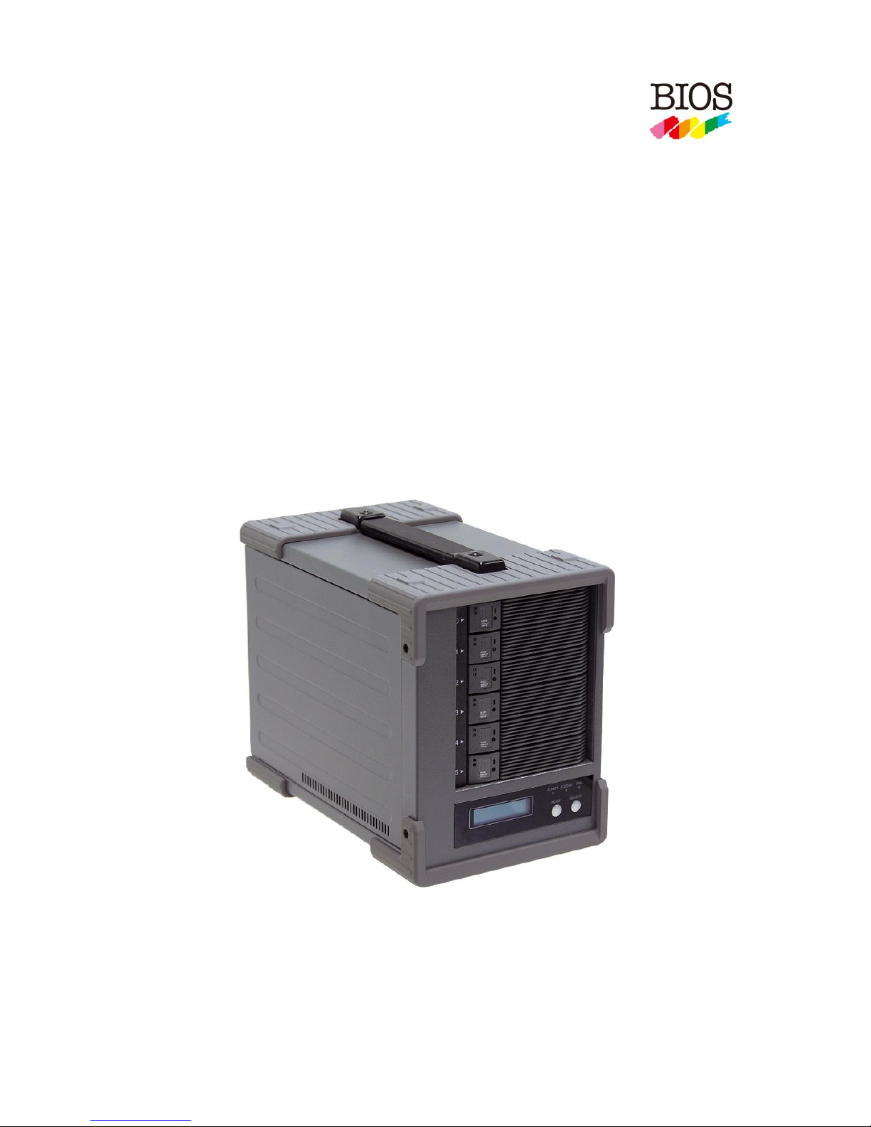
BR256(eSATA+USB2.0)model取扱説明書
- 0 -
Best
Energy
and Space Saving Best RAID
Portable RAID6, 2.5”HDD×6・Desktop Model
----------------------------------------------------------------------------
BR256
- eSATA+USB3.0 model -
【 User Manual 】
Revision 1.01f
----------------------------------------------------------------------------
Page 2
BIOS CORPORATION
- 1 -
Safety Warning
■ In order to avoid injury to oneself, equipment, and others, please heed the following instructions.
■ The following indications explain the degree of physical danger possible by ignoring the proper usage
directions.
The various types of warning symbols are listed in the following picture.
(The following provide examples of the warning drawings.)
This symbol means that you should pay extra attention.
This symbol indicates something you absolutely must not do.
This symbol indicates necessary actions you should take.
WARNING
This symbol is used to indicate sections that may
result in a serious injury or even death.
This symbol is used to indicate sections that might
pose a risk of minor injury or physical damage.
CAUTION
Page 3

BR256(eSATA+USB3.0)model User Manual
- 2 -
Prefix
Thank you for choosing our product: Best RAID 256 eSATA+USB3.0 (BR256 hereunder).
This user manual contains features, functions, setup, and warnings, so please read this manual prior to use
our product.
If any material in this manual is not clear, please contact manufacturer or vender where it was purchased.
● The information in this manual is subject to change without prior notice.
● It is prohibited to reproduce any part of this manual in any form or by any means without prior written
permission of the manufacturer and the author.
● Manufacturer assumes no liability or responsibility for any error that may appear in this manual. In case
issue raised please contact manufacturer or vender where this product was purchased.
● All trademarks stated in this manual are the properties of their respective owners.
Page 4
BIOS CORPORATION
- 3 -
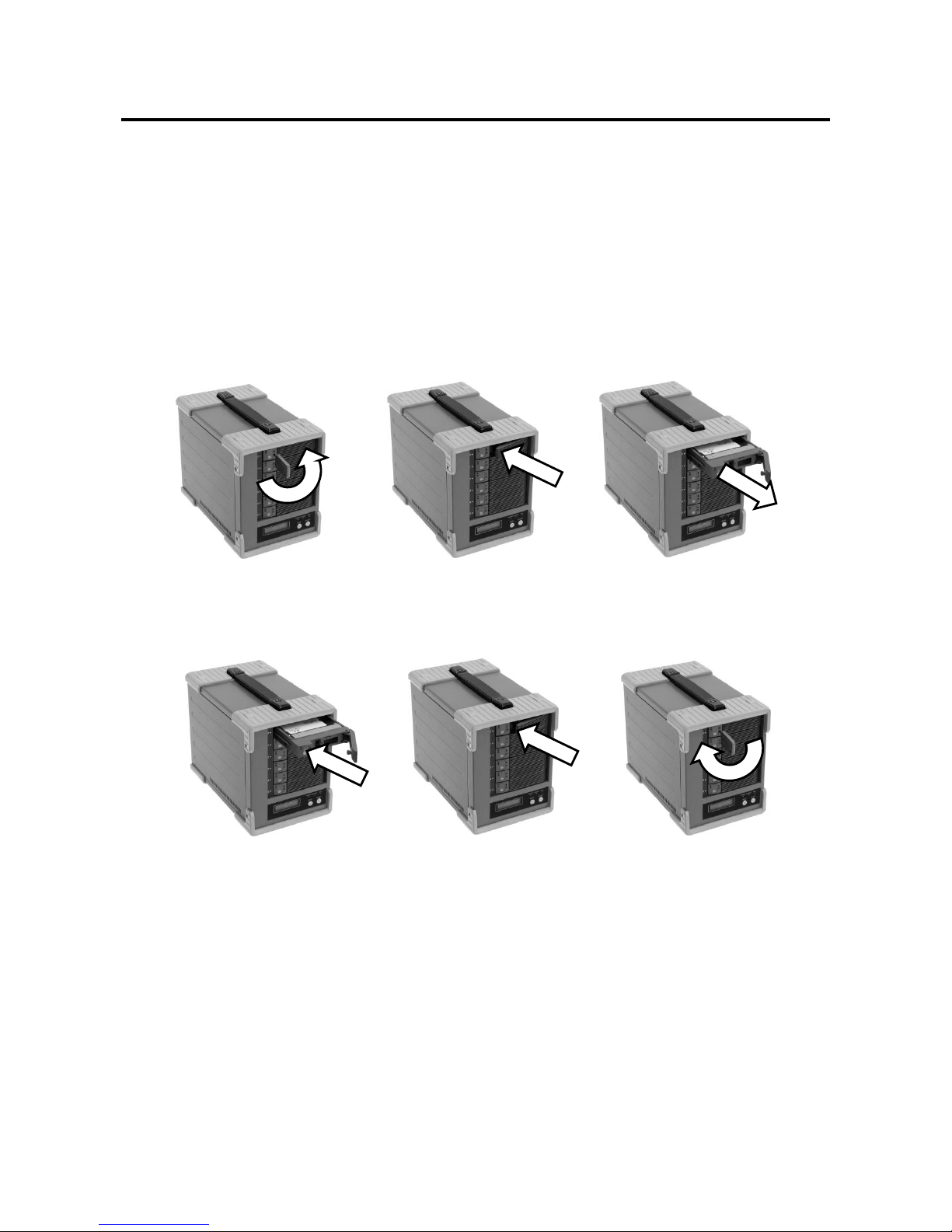
③ Pull out the lever and hold the
canister to remove HDD module
③ Insert the key and turn it
clockwise to lock the
module.
① Insert the key into the lock
hole and turn the key
counterclockwise.
② Push the lever of
canister
① Insert the HDD module
② Push the module into the
enclosure and close the lever
HDD Installation
■ Install and Remove HDD Module
① Before you start any operation, please make sure HDDs are installed properly into the BR256
enclosure
② An alarming beep sound will be turned on and caused error if right number of HDD module was not
installed properly
③ The system can be used only if the Array parameters have been set up properly.
■ Remove HDD Module
■ Install HDD Module
There are 4 screw holes on each HDD module. Use screws in accessory pack to screw HDD on the module.
Page 5
BR256(eSATA+USB3.0)model User Manual
- 4 -
Precautions for Product Usage
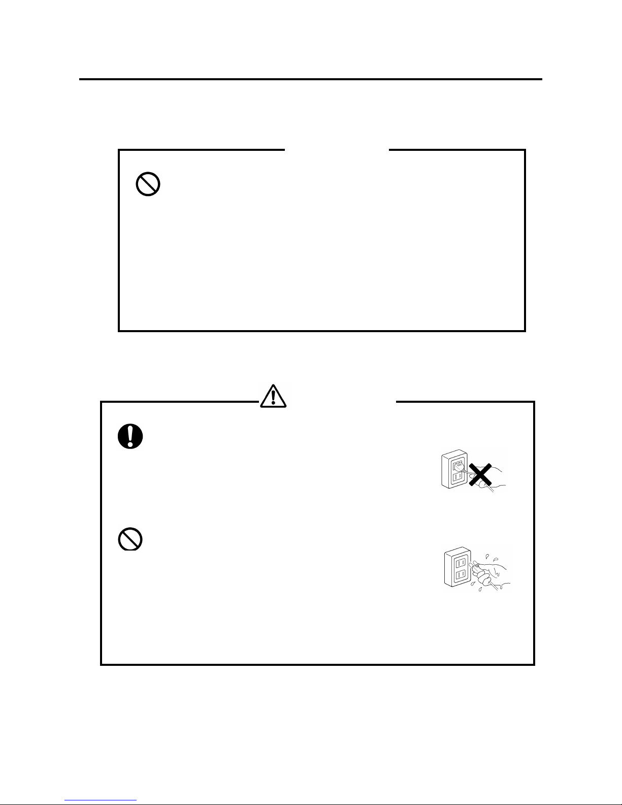
■ Treatment
● Don’t open up the cabinet.
You can be electrocuted.
● Don’t take it apart.
There is a chance to cause fire or injury
● Don’t modify.
There is a chance of fire.
● Don’t open the fan cover
There is a chance of injury
● Make sure to hold the plug when inserting or removing power cable.
There is a risk of electrocution.
● Don’t pull on the cable itself.
There is a chance of fire.
● Never operate unless the power plug is fully inserted.
It may short out and generate excessive heat, causing risk for a fire.
● Never insert or remove the cable with wet hands.
You may be electrocuted.
● Don’t remove the drive unit with your fingernails.
There is a risk of injury.
● When inserting disks don’t put your fingers in the unit case.
There is a risk of injury.
Don’t
CAUTION
Don’t
WARNING
Page 6
BIOS CORPORATION
- 5 -
● When removing the drive unit, be sure to use both hands.
You may drop it, causing injury.
● Never shut off the power while the drive is being accessed.
It may cause abnormal operation.
● Never remove the disk unit while it is being accessed.
It may cause abnormal operation.
● Use the original packing when transporting the unit.
It may fall and be damaged by shocks and impact.
● Keep your hands and fingers away from the fan when the case
is opened.
There is a risk of electrocution, fire, and injury.
● Don’t rub on edge of metal chassis.
There is a risk of injury.
● Don’t step on the unit.
There is a risk of injury and breakdown of the product.
● You cannot change the order of the drives once the RAID mode has been established
Please use the six drives in the order that they were installed at time of RAID creation.
● Please be sure to make proper backups of all data periodically
We do not guarantee data stored on HDDs. There might be risk due to software error or mishandling
causing data lost or broken. It is always recommended to back up your data periodically.
● Never use volatile chemicals (such as White Gasoline) or paint thinner
It may cause damage to the color or shape of the item.
If it does get dirty, please clean with a soft cloth and alcohol or soap.
● The unit is sensitive to sudden changes in temperature or humidity
If the unit runs overheat, please be sure to cease operation until the conditions return to normal.
Don’t
CAUTION
Page 7
BR256(eSATA+USB3.0)model User Manual
- 6 -
■ Placement
● Always use two hands when moving or transporting unit.
Injury can be caused if the item is dropped.
● Place the unit in an area that can sufficiently support its weight.
There is a risk of injury.
● Use a three-pronged outlet.
There is a risk of electrocution.
● Don’t use in places of extreme heat.
There is a risk of fire.
● Don’t use in very dusty or damp places.
There is a risk of fire.
● Don’t place in slant or unstable places.
It may fall and break, and may cause injury.
● Never use with more than the rated voltage.
There is a risk of electrocution.
● Don’t use the cable in anything but the approved power terminal.
There is a risk of injury.
● Don’t attempt to damage, repair, or burn the cable in any way.
If the power cable becomes damaged there is a risk of fire or electrocution.
● Don’t place the item in very hot places or in direct sunlight.
The room’s temperature may rise causing risk of damage.
● Never let the power cord get near a heater.
The coating on the cord may melt causing risk of a fire or electrocution.
Don’t
CAUTION
WARNING
Page 8
BIOS CORPORATION
- 7 -
● Turn the power switch off while connecting power cord.
There is a risk of electrocution.
● Remove the power plug upon any malfunction or breakdown.
There is a severe risk of fire or damage if you see smoke or smell any
strange scents coming from the unit. Power down at once and contact the
store where unit was purchased from.
● Never let the unit be near any magnets or equipment containing
magnets.
You may lose data from the hard disk.
● Do not leave the HDD module unlock
There is risk that HDD module falls out of the enclosure
●Never place the unit in any bags or containers containing
liquids.
There is a risk of fire inside the unite, or electrocution
●Keep the unit away from any shocks or vibrations.
The disk may sustain damage.
● Please do not use the unit while another high-power unit is on the same power
circuit.
● Do not use the unit in areas of high heat or humidity.
● Keep the unit away from televisions, radios, speakers, or any unit containing a
magnetic field.
● Don’t use the unit in any areas where liquid may get inside of it.
If liquid ever gets inside the case, remove the power cord at once.
Don’t
WARNING
Page 9

BR256(eSATA+USB3.0)model User Manual
- 8 -
‥‥‥‥‥‥‥‥‥‥‥‥‥‥‥‥‥‥‥‥‥‥‥‥‥‥‥‥‥‥‥‥‥‥‥‥‥‥‥‥‥‥‥‥‥‥‥‥
‥‥‥‥‥‥‥‥‥‥‥‥‥‥‥‥‥‥‥‥‥‥‥‥‥‥‥‥‥‥‥‥‥‥‥‥‥‥‥‥‥‥‥‥‥‥‥‥
‥‥‥‥‥‥‥‥‥‥‥‥‥‥‥‥‥‥‥‥‥‥‥‥‥‥‥‥‥‥‥‥‥‥‥‥‥‥‥‥‥‥‥‥‥‥‥‥
‥‥‥‥‥‥‥‥‥‥‥‥‥‥‥‥‥‥‥‥‥‥‥‥‥‥‥‥‥‥‥‥‥‥‥‥‥‥‥‥‥‥‥‥‥‥‥‥
‥‥‥‥‥‥‥‥‥‥‥‥‥‥‥‥‥‥‥‥‥‥‥‥‥‥‥‥‥‥‥‥‥‥‥‥‥‥‥‥‥‥‥‥‥‥‥‥
‥‥‥‥‥‥‥‥‥‥‥‥‥‥‥‥‥‥‥‥‥‥‥‥‥‥‥‥‥‥‥‥‥‥‥‥‥‥‥‥‥‥‥‥‥‥‥‥
‥‥‥‥‥‥‥‥‥‥‥‥‥‥‥‥‥‥‥‥‥‥‥‥‥‥‥‥‥‥‥‥‥‥‥‥‥‥‥‥‥‥‥‥‥‥‥‥
‥‥‥‥‥‥‥‥‥‥‥‥‥‥‥‥‥‥‥‥‥‥‥‥‥‥‥‥‥‥‥‥‥‥‥‥‥‥‥‥‥‥‥‥‥‥‥‥
‥‥‥‥‥‥‥‥‥‥‥‥‥‥‥‥‥‥‥‥‥‥‥‥‥‥‥‥‥‥‥‥‥‥‥‥‥‥‥‥‥‥‥‥‥‥‥‥
‥‥‥‥‥‥‥‥‥‥‥‥‥‥‥‥‥‥‥‥‥‥‥‥‥‥‥‥‥‥‥‥‥‥‥‥‥‥‥‥‥‥‥‥‥‥‥‥
‥‥‥‥‥‥‥‥‥‥‥‥‥‥‥‥‥‥‥‥‥‥‥‥‥‥‥‥‥‥‥‥‥‥‥‥‥‥‥‥‥‥‥‥‥‥‥‥
‥‥‥‥‥‥‥‥‥‥‥‥‥‥‥‥‥‥‥‥‥‥‥‥‥‥‥‥‥‥‥‥‥‥‥‥‥‥‥‥‥‥‥‥‥‥‥‥
‥‥‥‥‥‥‥‥‥‥‥‥‥‥‥‥‥‥‥‥‥‥‥‥‥‥‥‥‥‥‥‥‥‥‥‥‥‥‥‥‥‥‥‥‥‥‥‥
‥‥‥‥‥‥‥‥‥‥‥‥‥‥‥‥‥‥‥‥‥‥‥‥‥‥‥‥‥‥‥‥‥‥‥‥‥‥‥‥‥‥‥‥‥‥‥‥
‥‥‥‥‥‥‥‥‥‥‥‥‥‥‥‥‥‥‥‥‥‥‥‥‥‥‥‥‥‥‥‥‥‥‥‥‥‥‥‥‥‥‥‥‥‥‥‥
‥‥‥‥‥‥‥‥‥‥‥‥‥‥‥‥‥‥‥‥‥‥‥‥‥‥‥‥‥‥‥‥‥‥‥‥‥‥‥‥‥‥‥‥‥‥‥‥
‥‥‥‥‥‥‥‥‥‥‥‥‥‥‥‥‥‥‥‥‥‥‥‥‥‥‥‥‥‥‥‥‥‥‥‥‥‥‥‥‥‥‥‥‥‥‥‥
‥‥‥‥‥‥‥‥‥‥‥‥‥‥‥‥‥‥‥‥‥‥‥‥‥‥‥‥‥‥‥‥‥‥‥‥‥‥‥‥‥‥‥‥‥‥‥‥
‥‥‥‥‥‥‥‥‥‥‥‥‥‥‥‥‥‥‥‥‥‥‥‥‥‥‥‥‥‥‥‥‥‥‥‥‥‥‥‥‥‥‥‥‥‥‥‥
‥‥‥‥‥‥‥‥‥‥‥‥‥‥‥‥‥‥‥‥‥‥‥‥‥‥‥‥‥‥‥‥‥‥‥‥‥‥‥‥‥‥‥‥‥‥‥‥
‥‥‥‥‥‥‥‥‥‥‥‥‥‥‥‥‥‥‥‥‥‥‥‥‥‥‥‥‥‥‥‥‥‥‥‥‥‥‥‥‥‥‥‥‥‥‥‥
‥‥‥‥‥‥‥‥‥‥‥‥‥‥‥‥‥‥‥‥‥‥‥‥‥‥‥‥‥‥‥‥‥‥‥‥‥‥‥‥‥‥‥‥‥‥‥‥
‥‥‥‥‥‥‥‥‥‥‥‥‥‥‥‥‥‥‥‥‥‥‥‥‥‥‥‥‥‥‥‥‥‥‥‥‥‥‥‥‥‥‥‥‥‥‥‥
‥‥‥‥‥‥‥‥‥‥‥‥‥‥‥‥‥‥‥‥‥‥‥‥‥‥‥‥‥‥‥‥‥‥‥‥‥‥‥‥‥‥‥‥‥‥‥‥
‥‥‥‥‥‥‥‥‥‥‥‥‥‥‥‥‥‥‥‥‥‥‥‥‥‥‥‥‥‥‥‥‥‥‥‥‥‥‥‥‥‥‥‥‥‥‥
Page 10

BIOS CORPORATION
- 9 -
Table of Contents
Safety Warning .................................................................................................................... 1
Prefix .............................................................................................................................. 2
HDD Installation ................................................................................................................... 3
Precautions for Product Usage ............................................................................................ 4
Table of Contents ................................................................................................................ 9
Chapter 1. BR256 Outline ............................................................................................... 11
1.1 Features ............................................................................................................................................ 11
1.2 Function ............................................................................................................................................ 12
1.3 RAID Mode ....................................................................................................................................... 13
1.4 Contents of Packing ......................................................................................................................... 15
1.5 Name and Function of each part ...................................................................................................... 16
1.6 Connection ....................................................................................................................................... 18
1.7 Optional parts list .............................................................................................................................. 21
Chapter 2. Setup and Monitor ......................................................................................... 23
2.1 Toggle rolling setup flowchart ........................................................................................................... 23
2.2 Overview of Setup method ............................................................................................................... 24
2.3 Setup display navigation .................................................................................................................. 24
2.4 Parameter Setup Screen and its operations .................................................................................... 25
2.5 Background Parameters .................................................................................................................. 34
2.5.1 Method to setup background parameters ........................................................................... 34
2.5.2 Parameter Confirmation ...................................................................................................... 40
Quick Overview of From Panel Button Operation ........................................................................................ 43
2.6 Web-based Monitor and Setup via Ethernet .................................................................................... 44
2.6.1 Web Connection ................................................................................................................. 44
2.6.2 Main Menu .......................................................................................................................... 45
2.6.3 Monitor Mode ...................................................................................................................... 46
2.6.4 Management Mode ............................................................................................................. 49
2.6.5 Setup of email notification ................................................................................................... 51
2.6.6 Mail Format ......................................................................................................................... 53
2.6.7 Conditions of Mail Notification ............................................................................................ 53
2.7 Setup ................................................................................................................................................ 54
2.8 Host LAN Configuration.................................................................................................................... 60
2.8.1 IP Setup for Windows ......................................................................................................... 60
2.8.2 IP Setup for Linux ............................................................................................................... 62
2.8.3 IP Setup for MAC OS X ...................................................................................................... 63
Chapter 3. Format........................................................................................................... 66
3.1 Linux ................................................................................................................................................. 66
3.2 Windows 7 ........................................................................................................................................ 68
3.3 Other OSs ........................................................................................................................................ 74
Chapter 4. BR256 State Transition ................................................................................. 75
4.1 Overview of Disk Array State Transition ........................................................................................... 75
4.2 Deal with 「ONE DRIVE DOWN」state ............................................................................................. 77
4.3 Deal with 「TWO DRIVE DOWN」 .................................................................................................... 78
4.4 How to deal with 「SYSTEM DOWN」 .............................................................................................. 79
4.5 LCD Display Under Normal Operation ............................................................................................. 82
4.6 LCD Display for Disk Error ............................................................................................................... 82
Page 11

BR256(eSATA+USB3.0)model User Manual
- 10 -
4.7 LCD Display for Disk Drive Recovery Status ................................................................................... 83
4.8 LCD Display for FAN Failure ............................................................................................................ 83
4.9 Others LCD Display .......................................................................................................................... 84
4.9.1 Transfer Rate Display ......................................................................................................... 84
4.9.2 Cache Check Display ......................................................................................................... 84
4.9.3 Most Delay CH Display ....................................................................................................... 84
4.9.4 LCD Display for Patrol Mode Options ................................................................................. 85
4.9.5 LCD Display for Ethernet Setup .......................................................................................... 86
4.10 LCD Display for Controller Error ...................................................................................................... 86
4.11 Retry Error Detection/Drive SENSE DATA Display ......................................................................... 89
4.12 Other Error ....................................................................................................................................... 91
Appendix ............................................................................................................................ 93
1. Product Specification ........................................................................................................................ 93
2. Disk Time Out Value Setup .............................................................................................................. 94
3. How to change Cluster size(Allocation Unit Size) during Format under Windows OS .................... 95
4. To use SNMP MIB for Status Monitor ............................................................................................... 99
Page 12

BIOS CORPORATION
- 11 -
Chapter 1. BR256 Outline
1.1 Features
● Cable-less integrated RAID system
● Support six hot-swappable SATA hard disks
● Support RAID-6、RAID-0、RAID-3、RAID-5、RAID-1、RAID-1 3 DRIVE、RAID 10
● Support eSATA, USB3.0 and USB2.0 Interface; eSATA:3Gbits/sec (Theoretical value), USB3.0:
5Gbits/sec (Theoretical value), USB2.0: 480Mbits/sec (Theoretical value)
● Pure hardware based RAID-6/3/5 parity generator and high speed DMA
● 32 Bit RISC Processor 200MHz/400MIPS for command processing CPU
● LCD and keypad operation for status monitoring and system configuration
● Buzzer Alarm for fault indication
● Fault LEDs for drives and controller error indication
● Dual host and two LUNs support
● Spot Recovery Rewrite Function
Page 13

BR256(eSATA+USB3.0)model User Manual
- 12 -
1.2 Function
● eSATA:3Gbits/sec, USB3.0: 5Gbps/sec, USB2.0:480Mbits/sec
● Support RAID-6、RAID-0、RAID-3、RAID-5、RAID-1、RAID-1 3 DRIVE、RAID 10
● Priority configuration of Rebuild
● Adjustable cache size
● Write cache mode setup
● Verify mode setup
● LU(Logical Unit)Division Capability
● Adjustable RAID-5/6 Parity Strip size
● Data readahead setup
● Write Retry mode setup
● Buffer segment size setup
● Beginning time setup of Retry
● Sequential list setup
● Sequential read ahead setup
● Cache management configuration
● Detection time of low speed drive setup
● Power On standby time setup
● Drive Ready waiting time setup
● Check time of cache memory setup
● HDD Patrol setup
● Patrol waiting time setup
● Error message emailing SMTP support
● SNMP Trap Support
<Auxiliary Function>
● Performance (Data transfer rate) reading on LCD
● Drive channel retry display
● 100Mbps Ethernet Port for Web-based status monitoring
Page 14
BIOS CORPORATION
- 13 -
1.3 RAID Mode Explanation
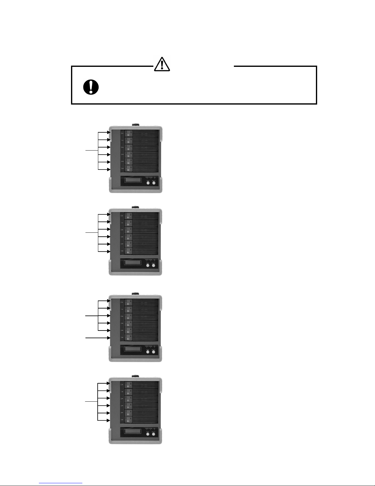
● Any change of RAID mode will cause data rebuild and data lost.
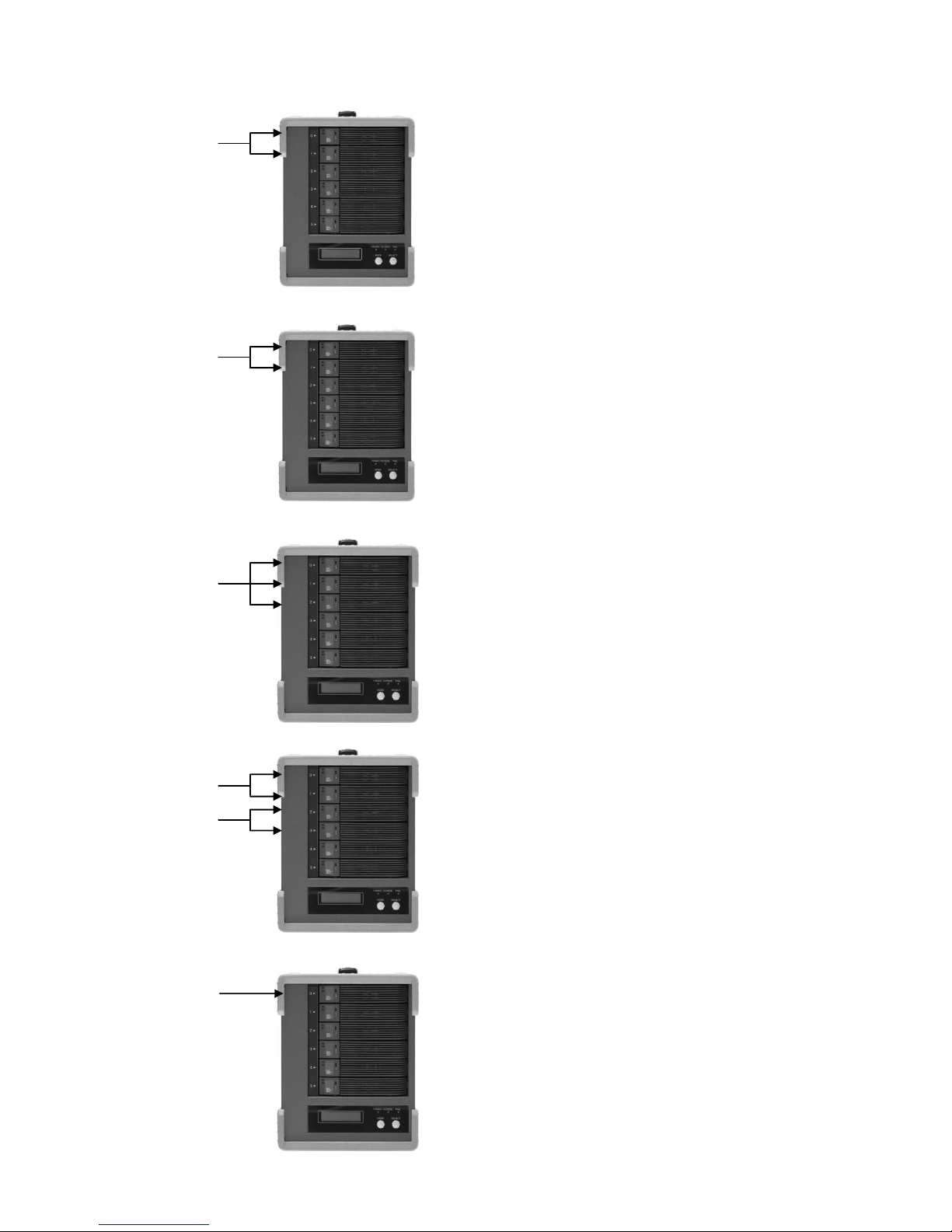
① RAID MODE 6
② RAID MODE 0
③ RAID MODE 3
④ RAID MODE 5
Data
Drive
Parity Data
Drive
Data and
parity are
equally
distribute
d among
6 drives
The most bottom drive is used for Parity
It allows one drive failure while data is accessing.
The data residing in failed drive can be generated from the
rest of 5 drives
Data and Parity are distributed among 6 HDDs. Since there
is no assigned disk for parity, each drive shares the same
loading in data access.
Data
Drive
All drives are used for data recording
Data is segmented and equally distributed among 6 drives.
All 6 drives will be accessed while data is read or written.
The mode provides the highest performance among all
others.
At the same time, if one drive failed, the whole data will be
lost.
Data and
Parity are
divided by
six
portions
Comparing with RAID- 5 dual parity is applied providing
even higher reliability
Allow up to two drives failure but also scarify capacity of two
drives
CAUTION
Page 15
BR256(eSATA+USB3.0)model User Manual
- 14 -
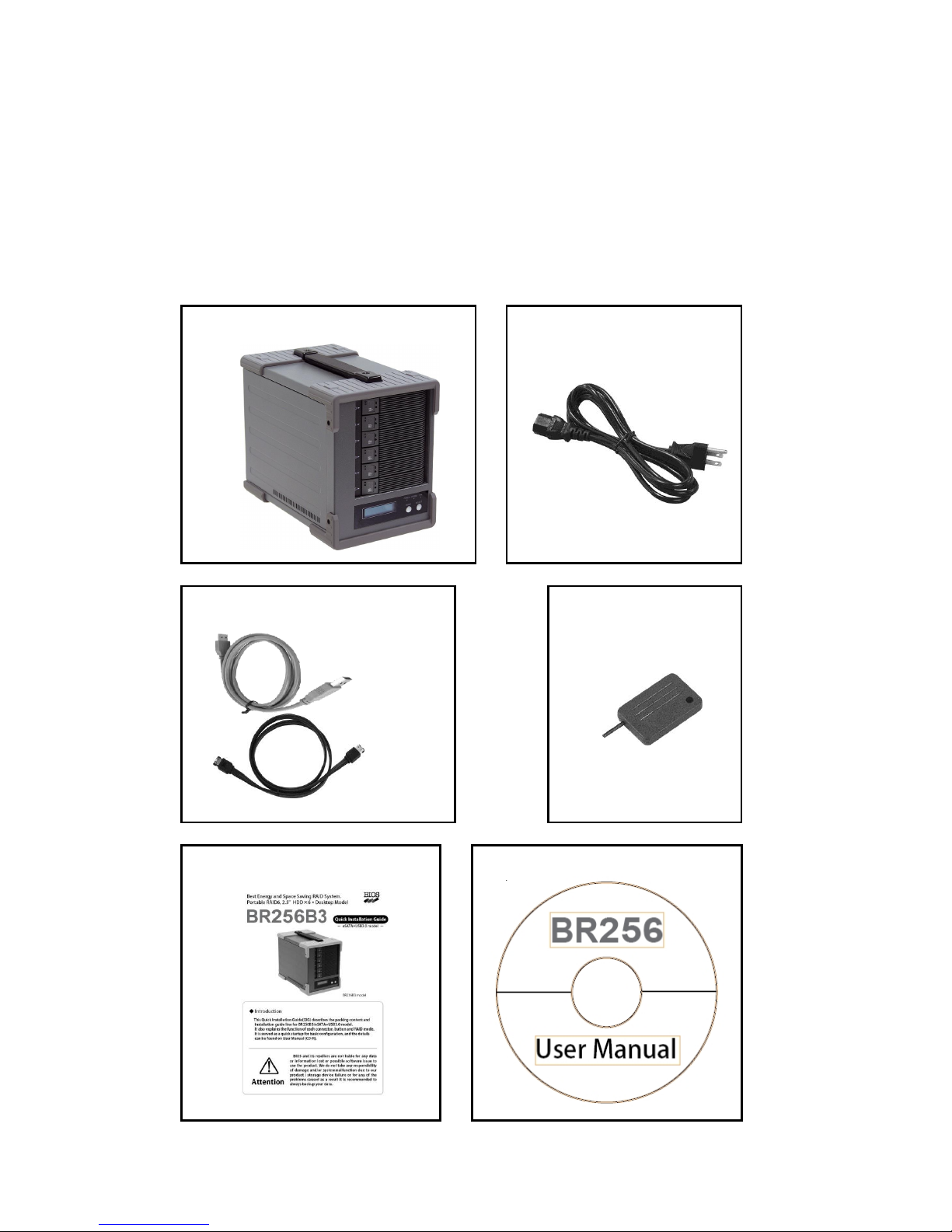
⑤ RAID MODE 1
⑥ RAID 0-2 DRIVE MODE
⑦ RAID 1 - 3 DRIVE MODE
⑧ RAID MODE 10
⑨SINGLE DRIVE MODE
Data Drive
Data Drive
Data Drive
Only one drive is used. Data cannot be recovered if the
drive is failed
In general, Data at RAID 1 is written to two drives at the same
time and read from one or both of drives.
Capacity is half the of the total physical disk capacity
Only two drives RAID-0 mode. (The rest of four drives
cannot be used)
There is no parity so the data cannot be recovered if any of
drive fault.
Data Drive
Three drive mirroring mode. Similar to RAID MODE1, Data is
written to all of three drives and read only from one or two
drives. Even two drives failed, the data can still be accessible.
The rest of three drives cannot be used.
It is the combination of RAID-0 and RAID-1.
Performance and security can be raised.
Stripe across mirrored Drive 0, 1 and Drive 2, 3
Capacity is equal to 2 drives capacity. Data can be accessed
even one of both mirrored pair drives failed. The rest of two
drives cannot be used.
Data Drive
Data Drive
Page 16
BIOS CORPORATION
- 15 -
1.4 Contents of Packing
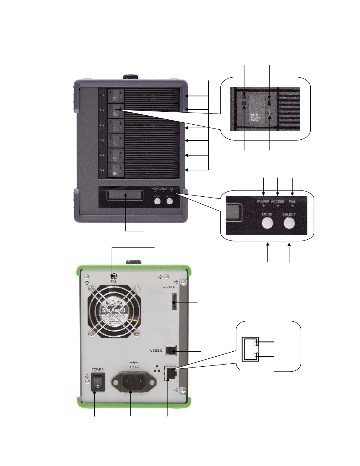
Please inspect if accessories are all included when the package is opened.
If you found missing items, please contact your reseller. And please keep the original packing carton
and materials.
<BR256 Accessories>
□ BR256
□ AC power cable×1
□ eSATA cable and USB3 cable
□ Drive Key
□ Quick Installation Guide
□ User Manual ( CD-R )
Page 17
BR256(eSATA+USB3.0)model User Manual
- 16 -
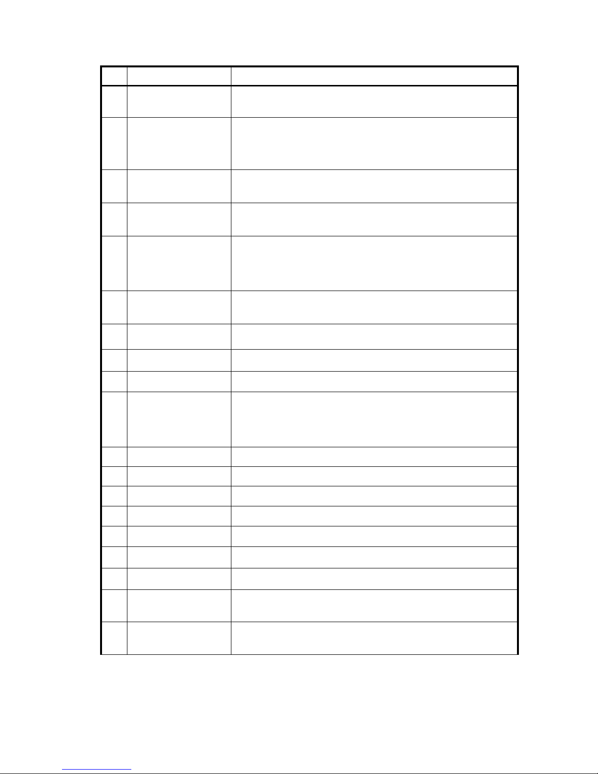
1.5 Name and Function of each part
< Front side >
< Rear Side >
⑧
① ④ ⑥ ⑦ ⑨
⑩ ⑫ ⑪
⑬
⑯
⑰
⑱ ⑲ ②
③ ⑤ ⑮
⑭
Page 18
BIOS CORPORATION
- 17 -
No.
Name
Function
①
HDD
Module
Hot-swappable drive module from top
No.0、No.1、No.2、No.3、No.4、No.5
②
HDD
POWER / FAIL
LED
HDD Power LED: Blue when ON, and Amber if the drive failed
When 「RAID-x RECOVERING 0%」shown on LCD, the FAIL LED
on means the HDD is under rebuilding
③
HDD
ACCESS LED
Green Flash indicates HDD being accessed
④
Lock Indicator
Orange indicates HDD module was locked
Gray indicates HDD module was unlocked
⑤
Key
Turn clockwise to lock the HDD module. Check the lock indicator to
see the status of module.
⑥
LCD
Display of BR256 status or parameter
⑦
POWER LED
Blue when system is turned on.
⑧
ACCESS LED
Green flash, when accessing the controller
⑨
FAIL LED
Orange ON when a pre-defined error encountered
⑩
MODE Button
1)Parameter Initialization (press upon power on)
2)Parameter setup. See Chapter 2
3)Stop buzzer alarm(press to turn off buzzer)
⑪
SELECT Button
Parameter setup
⑫
POWER Switch
Switch system power on/off
⑬
AC Connector
Connect AC Cable
⑭
FAN
Cooling fan
⑮
eSATA Connector
Host e-SATA connection
⑯
USB3 Connector
Host USB3.0 connection
⑰
Ethernet Link
LED
Orange ON indicates Link is setup
⑱
Ethernet Speed
LED
10Mbps Off,Green On for other speed
⑲
LAN Connector
Connect to Ethernet for web management
Page 19
BR256(eSATA+USB3.0)model User Manual
- 18 -
1.6 Connection
● Do not expose the unit under high temperature or directly sun light
For normal operation, adequate air condition to cool the unit is
necessary
● Never shut off the power while the drive is being accessed.
It may cause abnormal operation
● Do not use the unit over or under power input range
Unstable power input might cause the system unusable or malfunction
● Never insert or remove the cable with wet hands.
You may be electrocuted.
●When removing the drive unit, be sure to use both hands.
You may drop it, causing injury
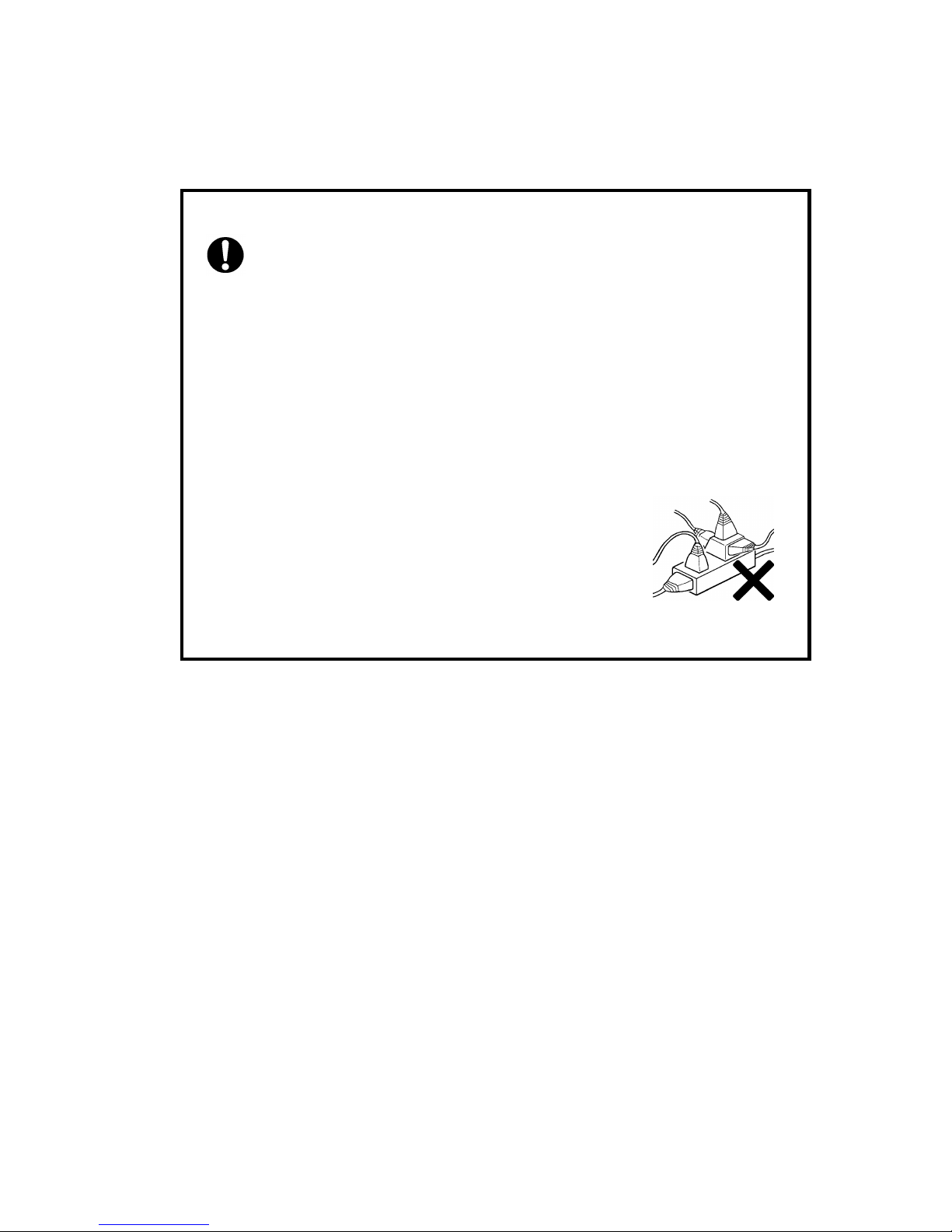
● Do not share the power plug with other high power
device
● Do not force the plug into the connector.
Please make sure the connector type correct before insertion
Page 20
BIOS CORPORATION
- 19 -
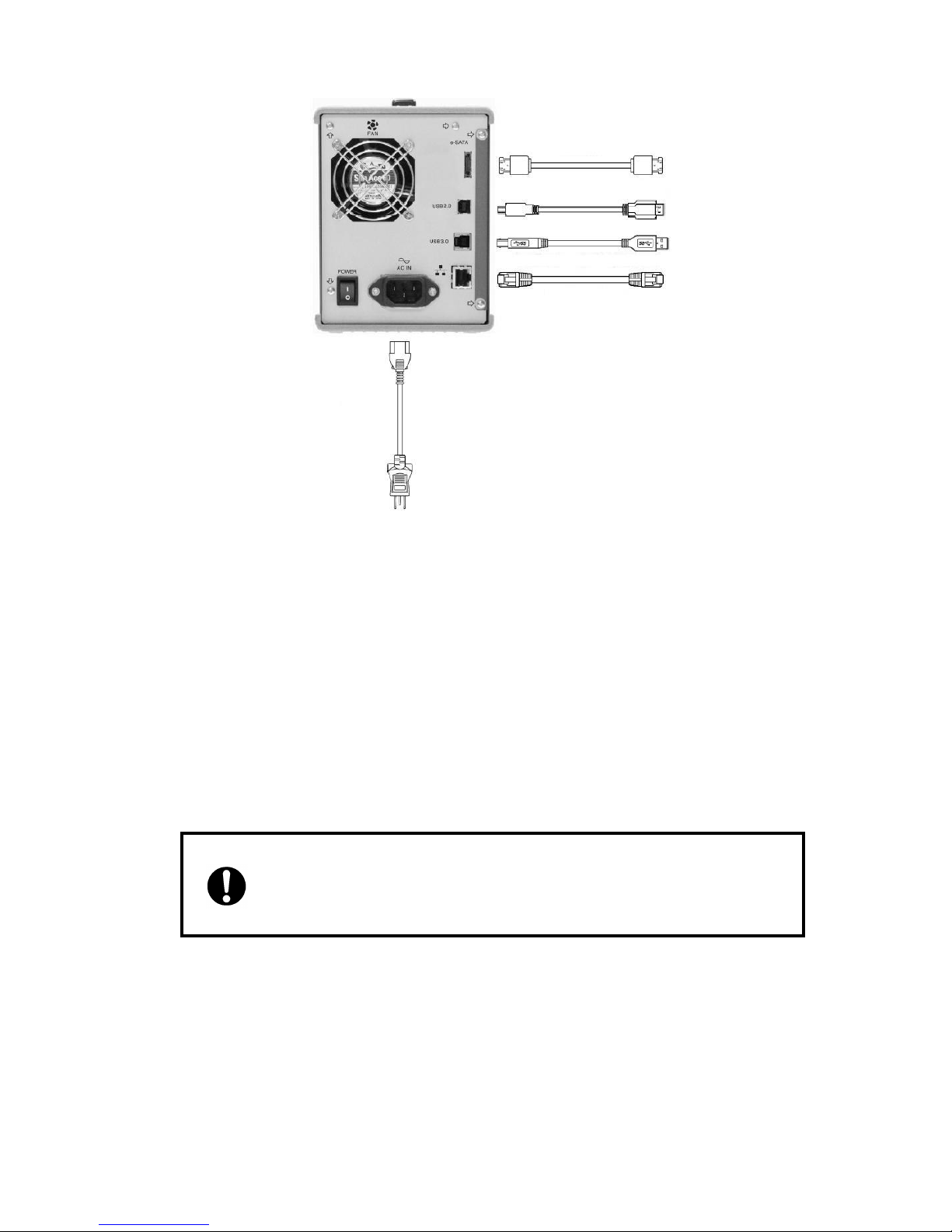
※ 1:Upon the host selection, the shape of connector might be different
※ 2:It is used for web-based monitor and configuration.
● Please do not connect eSATA and USB2.0 or USB3.0 at the same time
LAN Cable※2
(Optional)
AC Power
Cable
eSATA Cable
※1
Page 21
BR256(eSATA+USB3.0)model User Manual
- 20 -
< Steps for eSATA connection>
RAID(eSATA)→ PC(eSATA)
① Get the eSATA Cable inside the package connecting it between BR256 and the host.
② To use web-based monitor, connect Ethernet cable between LAN connector and host.
③ Connect AC power cable and turn on power switch at rear panel of BR256.
Turn on the host computer power and start the operation.
< Steps for USB2.0 or USB 3.0 connection>
① Turn on Host computer
② Connect USB 2.0 or USB 3.0 cable tightly between BR256 and host computer
③ To use web-based monitor, connect Ethernet cable between LAN connector and host
④ Connect AC power cable and turn on power switch at rear panel of BR256.
Turn on the host computer power and start the operation.
※Do not connect both USB2.0 or USB3.0 and eSATA at the same time while file system is running
Signal quality is different on SATA ports of motherboard. If you used SATA-eSATA
conversion cable with BR256, it might cause issues of recognition, transmission
or hot-plug. In that case, you might want to try the other SATA ports (as closed as
its chipset or controller) to see if the issues were gone. To assure stability and
reliability, it is recommended to use native eSATA ports or eSATA from a host bus
adapter.
Warning !
Page 22
BIOS CORPORATION
- 21 -
1.7 Optional parts list
● Spare HDD Module
Part Number
Description
BR256M0000
BR256 (Gray Module model) spare HDD module
● Send back Extension Service Pack
Part Number
Description
BR256-SEDBK-1Y
Extra one year sendback service (T otal: 2 years)
BR256-SEDBK-2Y
Extra two year sendback service (Total: 3 years)
BR256-SEDBK-3Y
Extra three year sendback service (Total: 4 years)
BR256-SEDBK-4Y
Extra four year sendback service (Total: 5 years)
※ First year sendback service is included at the product purchased.
Page 23

BR256(eSATA+USB3.0)model User Manual
- 22 -
‥‥‥‥‥‥‥‥‥‥‥‥‥‥‥‥‥‥‥‥‥‥‥‥‥‥‥‥‥‥‥‥‥‥‥‥‥‥‥‥‥‥‥‥‥‥‥‥
‥‥‥‥‥‥‥‥‥‥‥‥‥‥‥‥‥‥‥‥‥‥‥‥‥‥‥‥‥‥‥‥‥‥‥‥‥‥‥‥‥‥‥‥‥‥‥‥
‥‥‥‥‥‥‥‥‥‥‥‥‥‥‥‥‥‥‥‥‥‥‥‥‥‥‥‥‥‥‥‥‥‥‥‥‥‥‥‥‥‥‥‥‥‥‥‥
‥‥‥‥‥‥‥‥‥‥‥‥‥‥‥‥‥‥‥‥‥‥‥‥‥‥‥‥‥‥‥‥‥‥‥‥‥‥‥‥‥‥‥‥‥‥‥‥
‥‥‥‥‥‥‥‥‥‥‥‥‥‥‥‥‥‥‥‥‥‥‥‥‥‥‥‥‥‥‥‥‥‥‥‥‥‥‥‥‥‥‥‥‥‥‥‥
‥‥‥‥‥‥‥‥‥‥‥‥‥‥‥‥‥‥‥‥‥‥‥‥‥‥‥‥‥‥‥‥‥‥‥‥‥‥‥‥‥‥‥‥‥‥‥‥
‥‥‥‥‥‥‥‥‥‥‥‥‥‥‥‥‥‥‥‥‥‥‥‥‥‥‥‥‥‥‥‥‥‥‥‥‥‥‥‥‥‥‥‥‥‥‥‥
‥‥‥‥‥‥‥‥‥‥‥‥‥‥‥‥‥‥‥‥‥‥‥‥‥‥‥‥‥‥‥‥‥‥‥‥‥‥‥‥‥‥‥‥‥‥‥‥
‥‥‥‥‥‥‥‥‥‥‥‥‥‥‥‥‥‥‥‥‥‥‥‥‥‥‥‥‥‥‥‥‥‥‥‥‥‥‥‥‥‥‥‥‥‥‥‥
‥‥‥‥‥‥‥‥‥‥‥‥‥‥‥‥‥‥‥‥‥‥‥‥‥‥‥‥‥‥‥‥‥‥‥‥‥‥‥‥‥‥‥‥‥‥‥‥
‥‥‥‥‥‥‥‥‥‥‥‥‥‥‥‥‥‥‥‥‥‥‥‥‥‥‥‥‥‥‥‥‥‥‥‥‥‥‥‥‥‥‥‥‥‥‥‥
‥‥‥‥‥‥‥‥‥‥‥‥‥‥‥‥‥‥‥‥‥‥‥‥‥‥‥‥‥‥‥‥‥‥‥‥‥‥‥‥‥‥‥‥‥‥‥‥
‥‥‥‥‥‥‥‥‥‥‥‥‥‥‥‥‥‥‥‥‥‥‥‥‥‥‥‥‥‥‥‥‥‥‥‥‥‥‥‥‥‥‥‥‥‥‥‥
‥‥‥‥‥‥‥‥‥‥‥‥‥‥‥‥‥‥‥‥‥‥‥‥‥‥‥‥‥‥‥‥‥‥‥‥‥‥‥‥‥‥‥‥‥‥‥‥
‥‥‥‥‥‥‥‥‥‥‥‥‥‥‥‥‥‥‥‥‥‥‥‥‥‥‥‥‥‥‥‥‥‥‥‥‥‥‥‥‥‥‥‥‥‥‥‥
‥‥‥‥‥‥‥‥‥‥‥‥‥‥‥‥‥‥‥‥‥‥‥‥‥‥‥‥‥‥‥‥‥‥‥‥‥‥‥‥‥‥‥‥‥‥‥‥
‥‥‥‥‥‥‥‥‥‥‥‥‥‥‥‥‥‥‥‥‥‥‥‥‥‥‥‥‥‥‥‥‥‥‥‥‥‥‥‥‥‥‥‥‥‥‥‥
‥‥‥‥‥‥‥‥‥‥‥‥‥‥‥‥‥‥‥‥‥‥‥‥‥‥‥‥‥‥‥‥‥‥‥‥‥‥‥‥‥‥‥‥‥‥‥‥
‥‥‥‥‥‥‥‥‥‥‥‥‥‥‥‥‥‥‥‥‥‥‥‥‥‥‥‥‥‥‥‥‥‥‥‥‥‥‥‥‥‥‥‥‥‥‥‥
‥‥‥‥‥‥‥‥‥‥‥‥‥‥‥‥‥‥‥‥‥‥‥‥‥‥‥‥‥‥‥‥‥‥‥‥‥‥‥‥‥‥‥‥‥‥‥‥
‥‥‥‥‥‥‥‥‥‥‥‥‥‥‥‥‥‥‥‥‥‥‥‥‥‥‥‥‥‥‥‥‥‥‥‥‥‥‥‥‥‥‥‥‥‥‥‥
‥‥‥‥‥‥‥‥‥‥‥‥‥‥‥‥‥‥‥‥‥‥‥‥‥‥‥‥‥‥‥‥‥‥‥‥‥‥‥‥‥‥‥‥‥‥‥‥
‥‥‥‥‥‥‥‥‥‥‥‥‥‥‥‥‥‥‥‥‥‥‥‥‥‥‥‥‥‥‥‥‥‥‥‥‥‥‥‥‥‥‥‥‥‥‥‥
‥‥‥‥‥‥‥‥‥‥‥‥‥‥‥‥‥‥‥‥‥‥‥‥‥‥‥‥‥‥‥‥‥‥‥‥‥‥‥‥‥‥‥‥‥‥‥‥
‥‥‥‥‥‥‥‥‥‥‥‥‥‥‥‥‥‥‥‥‥‥‥‥‥‥‥‥‥‥‥‥‥‥‥‥‥‥‥‥‥‥‥‥‥‥‥‥
Page 24
BIOS CORPORATION
- 23 -
Chapter 2. Setup and Monitor
2.1 Toggle rolling setup flowchart
ARRAY PARAMETERS
SETTING!
: Initial Display
↓
SATA HOST
: Enable or Disable eSATA Host
↓
USB3 HOST
: Enable or Disable USB3 Host
↓
RAID MODE SETUP
: RAID Mode Setup
↓
RECOVER WAIT SETUP
: Recovery Time Setup
↓
CACHE SIZE SETUP
: Cache Size Setup
↓
WRITE MODE SETUP
: Write Cache Mode Setup
↓
VERIFY WAIT SETUP
: Verify Mode Setup
↓
LUN SIZE SETUP
: Logical Unit Size Setup
↓
LUN MODE SETUP
: Logical Unit Mode Setup
↓
DRIVE MODE SETUP
: Drive Mode Setup
↓
PARITY STRIPE SETUP
: Parity Stripe Size Setup
↓
READ AHEAD SETUP
: Data Read Ahead Setup
↓
DISK TYPE SETUP
: Drive Type Setup
Normally, users do not
need to change the
default setting.
Please make sure you
understand the function
before making any
change.
Page 25

BR256(eSATA+USB3.0)model User Manual
- 24 -
2.2 Overview of Setup method
To simplify the procedure of setup, BR256 is designed to support all of setup options by front panel LCD.
The default configuration and parameters are default for RAID-6 mode. BR256 is supposed to up and run
without changing default setting unless a special configuration needed. To prevent malfunction, BR256
setting cannot be changed during operation
2.3 Setup display navigation
This section will go through the parameters setup displayed on LCD screen.
If this is first time to power on the unit, an Initialization Procedure should be done first. When powering up
the BR256 unit, press and hold the Mode button (besides LCD) at power on. (Notice: this will clean up
the system status and parameters recorded in non-volatile memory.)
(Without performing initialization, the LCD display might show「RAID-x ONE DRIVE DOWN」、「SYSTEM
DOWN」indicating the status of last time. A normal display with drives properly populated will look like
RAID-6
NORMAL
To change Parameters, BR256 needs to be powered on for Parameter Setup mode. Press the Mode
and Select buttons at the same time while turning on power switch. Under Parameter Setup mode,
users can also configure parameters via Ethernet connection and perform firmware upgrade.
ARRAY PARAMETERS
SETTING!
MODE Button: To roll through each parameter
SELECT Button: Choose and change the parameter
Before executing Save operation, parameters won’t be changed.
●Parameter Setup Mode
:MODE Button + SELECT Button + Power ON
●Rotate among Setup items
●Setup parameters
To save changed parameters, pressing MODE and SELECT button once at the same time, parameters
will be written to internal non-volatile memory then the change is recorded.
When you successfully change the parameter, you will see
POWER DOWN
PLEASE!
Then please power cycle the system or press SELECT button for 3 seconds to take parameters effective.
Page 26
BIOS CORPORATION
- 25 -
If you power down before saving to memory, the settings will revert to the way they were upon the last
save.
● Saving the change :
① MODE + SELECT Button
② Power OFF or press SELECT Button 3 sec
● Cancel the change
2.4 Parameter Setup Screen and its operations
This section explains each parameter and the associated function of BR256.
PS. Please take a memo if you changed parameters different from its default value
● RAID Mode Setup
RAID MODE
RAID-6
Select RAID Mode
Parameter
Function
Memo
RAID MODE
RAID-6
Setup RAID 6. Please refer to Sec 1.3
Default
RAID MODE
RAID-0
Please refer to Sec 1.3
RAID MODE
RAID-3
Please refer to Sec 1.3
RAID MODE
RAID-5
Please refer to Sec 1.3
RAID MODE
RAID-1
Please refer to Sec 1.3
RAID-0
2 DRIVE MODE
Please refer to Sec 1.3
RAID-1
3 DRIVE MODE
Please refer to Sec 1.3
RAID MODE
RAID-10
Please refer to Sec 1.3
SINGLE DRIVE
MODE
Please refer to Sec 1.3
Page 27

BR256(eSATA+USB3.0)model User Manual
- 26 -
● Recovery Rate Setup
RECOVER RATE
5Min. /GB
Recovery operations utilize time between host data access without interrupting the current job.
Therefore data read/write can be continued without interruption.
User can choose the timing to execute recovery operations as below.
Parameter
Function
Memo
RECOVER
WAIT
TIME 0 Sec
Recovery request will be processed immediately between host
commands. Recovery will always be processed therefore host
access will be slow down. Select this mode if you want the
recovery have high priority.
RECOVER
WAIT
TIME 0.1 Sec
Continuous host commands will be processed first. Recovery
operation will be taken care when the interval between host
commands longer than 0.1 sec. The following host command has
to wait till one recovery task completed except READ/WRITE or
READ Cache command which will be executed immediately.
RECOVER
WAIT
TIME 1 Sec
This can be used when host access are not concentrated.
The wait interval following the last host command is 1 sec. On
this mode, the recovery operation will not be processed if the
host commands are continuous with less than 1 sec internal.
RECOVER
WAIT
TIME 10 Sec
Usually this should not be used.
Probably this mode can be applied if there is very little host
access.
RECOVER
RATE
2Min./GB
5Min./GB
10Min./GB
20Min./GB
This is to assign a fixed recovery time for 1GB capacity despite of
interval to wait between host commands.
Yet there is possibility that 5Min./GB cannot be finished in
time
Default
5Min./GB
Page 28
BIOS CORPORATION
- 27 -
● Cache size Setup
CACHE SIZE
128MB
To setup the cache size of BR256
Please do not alter the cache size if you did not change the cache memory
Parameter
Function
Memo
CACHE SIZE
64MB
128MB
「Cache Buffer Error」will be shown if the selected cache
size not matched the installed cache memory
Default
128MB
● Write Cache Mode Setup
WRITE ALL
PENDING 0.1Sec
The controller needs more time than writing to single drive to generate parity while doing RAID-3/5/6
WRITE. Therefore Write Cache is enabled in such situation.
This parameter defines the timing to wait before starting to move cache contents into disks.
Parameter
Function
Memo
WRITE MODE
WAITING
Under this setting, the Write operation will not be acknowledged
as “Completed” till data is written into disks. This means no
caching is used during data write. The performance is slower
compared to 「WRITE MODE PENDING」mode. READ speed is
not affected.
WRITE MODE
BUFFERD
Write command is acknowledged as “Completed” right after data
written into cache, and cached data starts to be moved into disks
at the same time.
WRITE MODE
PENDING
0.1Sec
After finishing a host command, this mode will wait 0.1 seconds
and start to write data before the next command. When doing
sequential writes, cache will be filled by multiple write command
and data can be written once to save total write time.
WRITE MODE
PENDING
1 Sec
Similar to PENDING 0.1 sec, the wait interval is one second.
WRITE ALL
PENDING
0.1Sec
1 Sec
This mode is set as default to enable Write cache even one drive
is failed.
Default
Page 29
BR256(eSATA+USB3.0)model User Manual
- 28 -
● Verify Mode Setup
VERIFY WAIT
READ aft WRITE
Verify Mode specifies when and how to perform the data verification. You can wait until the verification
to be done with [Verify Wait] mode. If you’d like to do the writes without verifying you can specify [No
Verify] mode.
Also, you can choose to read the data off the disk after it has been written from cache when a read
request takes place [READ aft WRITE], or you can choose not to verify it at all after the write [NO READ
aft WRT]
Parameter
Function
Memo
VERIFY
WAIT
The Write command cannot be completed at the time data written
into cache. It has to wait till Write and Verification command
completed.
Default
NO VERIFY
There is no verification operation when doing Write & Verify
under such mode. A simple write will be executed. Verify
command is not affected by this setting.
READ aft
WRITE
Instead of Verify command, sometimes READ command usually
follows a series of Write command to compare and verify the
written data. It is meaningless if cache data is used upon READ
command received. This parameter is to clean up cache data
after WRITE, and force data to be read from disks when READ
command is received.
Default
NO READ aft
WRT
This mode assumes write operation can be continued when data
is into cache before moving to disk. And also it assume there is
no more than one drive failed at the same time under RAID-3/5
setting. The data written into cache becomes effective
immediately.
Page 30
BIOS CORPORATION
- 29 -
● LUN SIZE Setup
LUN SIZE
Max 2TB
Parameter
Function
Memo
LUN SIZE
FULL
Use up all disk size as one single LUN.
Depend on host operating system, LUN over 2TB size might
not be recognized.
Default
LUN SIZE
16GB~256GB
LUN size is assigned to different size 16GB, 32GB, 64GB,
128GB, 256GB partitioned from LBA 0 of each disk member
LUN SIZE
MAX 2TB
MAX 2TB/2
MAX 2TB/3
MAX 2TB/4
LUN size is assigned to 2TB, 2TB/2, 2TB/3 and 2TB/4
partitioned from LBA 0 of the disk member.
Default
MAX 2TB
LUN SIZE
1/2 ~ 1/8
DIVISION
LUN size is equally divided as 1/2、1/3、1/4、1/5、1/6、1/7、
1/8 of the whole useful disk size.
LUN SIZE
64GB + ALL
64GB + Max2TB
Set up one LUN as 64GB and the rest of all as 2nd LUN (2nd
LUN maximum is 2TB.
※If you would like to use LUN more than 2TB, then 「LUN SIZE FULL」should be selected.
Page 31
BR256(eSATA+USB3.0)model User Manual
- 30 -
●LUN MODE Setup
LUN DIRECT
No BIAS
Parameter
Function
Memo
LUN DIRECT
No BIAS
※Please refer to below explanation
Default
LUN SWAPPED
No BIAS
※Please refer to below explanation
LUN DIRECT
for MBR(-1)
※Please refer to below explanation
LUN SWAPPED
for MBR(-1)
※Please refer to below explanation
LUN DIRECT
for MBR(+1)
※Please refer to below explanation
LUN SWAPPED
for MBR(+1)
※Please refer to below explanation
LUN DIRECT
for MBR(-2)
※Please refer to below explanation
LUN SWAPPED
for MBR(-2)
※Please refer to below explanation
※LUN SWAPPED function is reserved for future dual host usage not applicable to BR256.
※Sector management of RAID are different between [NO BIAS] and [for MBR(-1) or (+1) or(-2)]
Depend on host OS used, the beginning address of device might be different. And the setting might be
helpful to improve the performance. The setting should not be changed during operation otherwise data
will be lost. Format operation is necessary if this parameter is changed.
● Drive Mode Setup
DRIVE MODE
6
Setup number of drives in used on RAID 6
Parameter
Function
Memo
DRIVE MODE 3
3 Disks(DATA+PARITY)Mode
DRIVE MODE 4
4 Disks(DATA+PARITY)Mode
DRIVE MODE 5
5 Disks(DATA+PARITY)Mode
DRIVE MODE 6
6 Disks(DATA+PARITY)Mode
Default
Page 32
BIOS CORPORATION
- 31 -
● Parity Stripe Width Setup
PARITY STRIPE
2 MB/DRIVE
Choose stripe width of RAID-5/6 LUN
Parameter
Function
Memo
PARITY STRIPE
2 MB/DRIVE
1MB/DRIVE
256KB/DRIVE
128KB/DRIVE
Setup stripe width of each drive channel.
When the host issues a command, and the parity is to be
written, the command is divided up into two or more
operations. A relatively big stripe width is setup to reduce the
overhead of continuous operation.
The bigger size of stripe width, faster transfer speed can be
achieved for sequential read or write. Usually 「 2MB/
DRIVE」 setup will give a good performance but it depends
on the host application.
Default
2 MB/DRIVE
Page 33
BR256(eSATA+USB3.0)model User Manual
- 32 -
● Read Ahead Size Setup
READ AHEAD
64 KB
This is to set size of data to pre-fetch into cache for read operation.
Parameter
Function
Memo
READ AHEAD
0 KB
Do not do read ahead.
You might like to use this setting if read data is frequently
changed across different directories
READ AHEAD
8 KB
The read ahead size is 8KB, i.e. one page same as buffer
segment size. This might be effective for general random
operation.
READ AHEAD
64 KB
This will read ahead multiple pages following the current one
page. This is effective for general sequential read.
Default
READ AHEAD
256 KB
Compared to 64KB, one more page or 256KB will be pre-fetched
depend on page size.
This is effective for sequential access especially video data.
READ AHEAD
1 MB
1MB or multiple page read ahead depend on page size.
It will be effective if the data size is times of MBs.
READ AHEAD
4 MB
4MB size read ahead. This might be effective if the application
read directly block data without through file system.
Page 34
BIOS CORPORATION
- 33 -
●Disk Type Setup
DISK TYPE
xxxxB
TEST1GB, 120GB, 160GB
250GB, 400GB, 500GB,
750GB, 1TB, 2TB, 3TB, 4TB
This is to specify the size of the drive you will be using.
(Unless you plan to use different disks than the ones provided, there is no need to change this setting.
The factory default is for 1GB. With HDD installed and power on first time, please change the disk type
at Setup Mode)
● Please do not change the default setting
If drive actual capacity was smaller than the setup disk type, an error such
as「ONE DOWN L」、「SYSTEM DOWN L」might happen and buzzer will
be fired.
Page 35
BR256(eSATA+USB3.0)model User Manual
- 34 -
2.5 Background Parameters
This section describes background parameters for maintenance configured before shipment.
There are two parts of these parameters, Fixed and Changeable ones.
Changeable background parameters follow with fixed parameters.
Please take a memo before you apply to change the default parameter value. Refer to
Sec.2.5.2 Parameter Confirmation. Default setting is always recommended unless
there is special requirement for the change.
2.5.1 Method to setup background parameters
Please make sure you understand exactly the purpose that you are changing from the default
parameters.
1.Holding both the Mode and Select button, power up.
ARRAY PARAMETERS
SETTING!
2.Press the SELECT button, Fixed Parameters start with Firmware version
Firm ware is
Ver.x.xxx
Firmware version will be displayed
3.Press the SELECT button
Vender ID is
BIOS
Vendor ID will be displayed
4.Press the SELECT button
Product ID is
BR256B3-xxx6
Product ID will be displayed
5.Press the SELECT button
Serial No ID
xxxxxxxx
Serial number of BR256 will be displayed
6.Press the SELECT button
End of
Fixed Parameter
Indicate the end of the fixed parameters.
After fixed parameters, if you press the Mode button now, you will enter Background Parameter mode.
Page 36
BIOS CORPORATION
- 35 -
Or you can directly get into Background parameters by pressing the Mode button any time during display
among Firmware Version、Vendor ID、Device ID、Serial Number.
From here, pressing the Mode button to roll among changeable Background parameters.
● IP Address Setup
IP Address
192.168.50.210
By pushing SELECT button, the IP Address will be increased.
The longer you hold the SELECT button, the faster the number is increased.
Push the MODE button to move to next field.
● Address Mask Setup
Address Mask
255.255.255.0
This is to setup IP address mask same as IP setup.
● Parity Mode Setup
ENABLE
PARITY
ENABLE、DISABLE
Enable or Disable Parity
● Host Active Speed Setup
Host 3Gbps
SSC RCV Cap
1.5Gbps SSC RCV Cap、
1.5Gbps No SSC RCV Cap、
3.0Gbps SSC RCV Cap、
3.0Gbps No SSC RCV Cap
This is to setup the maximum host speed
● USB Port Setup
USB2 Port
Enabled
ENABLE、DISABLE
Enable or Disable USB2 port connectivity
Page 37

BR256(eSATA+USB3.0)model User Manual
- 36 -
● Maximum Drive Sequential Transmission Speed SSC Setup
Disk 1.5Gbps
No SSC Rcv Cap
1.5Gbps SSC RCV Cap、
1.5Gbps No SSC RCV Cap、
3.0Gbps SSC RCV Cap、
3.0Gbps No SSC RCV Cap
The setup is to setup maximum drive speed and SSC(Spectrum Scatter Clock). Depend on hard disk;
SSC might affect the stability of data access. Please check your hard disk specification and adjust if
necessary.
● Flush cache command setup
Ignore
FLUSH CACHE
Enable / Ignore
Enable or Ignore「FLUSH CACHE」command function. Default is “Ignore”
【 Ignore 】RAID cache data will not be written to disk from cache when Flush Cache was received. This
will improve the file access performance and is recommended. Usually RAID cache size is bigger than hard
disk cache so writing data from RAID cache to disk will spend longer time.
【 Enable 】When File Close is executed, the Flush Cache command will be followed to have Cache data
written into HDD. HDD will also synchronize cache till Write operation finished.
● Background Write Setup
WRITE BACK MAX
SIZE 4MB/CH
64KB / 128KB / 256KB / 512KB /
1MB / 2MB /4MB
Setup the maximum size of data stored in cache for Sequential Write
When data size written to cache is bigger than the setup size, data will be partitioned to parts
for writing.
● Write Retry Mode Setup
WRITE RETRY
MODE
NO WRITE RETRY MODE/
WRITE RETRY MODE
Enable or disable RETRY; controller will retry the operation when an error is detected during RAID-3/5/6
Write operation. If NO WRITE RETRY MODE is set, an error will immediately move the controller status to
「ONE DOWN」
Page 38

BIOS CORPORATION
- 37 -
● Buffer Segment Size Setup
BUFFER SEGMENT
SIZE 64KB/CH
8KB/CH,16KB/CH,32KB/CH,64KB/CH
Setup buffer segment size per drive channel. This is the size of data block for one command. For large
sequential data access, the bigger size can give better performance. On the contrast, for random access, the
smaller size can give better performance.
● Wait Time of Retry Setup
RETRY MAXIMUM
TIME 5S
25S/10S/5S/1S/0.1S
Setup the interval between drive time out and retry.(「1S」,「0.1S」is only for testing)
The actual processing time will take 2 or 3 times of the setting. OS might need to setup a longer time out
interval because of the longer retry processing on storage system.
● Sequential List Size Setup
SEQUENTIAL LIST
SIZE 8
8/16/32/64
This is to setup a table size of judging the access pattern as Sequential or Random. It depends on also
simultaneous number of streams and size of cache memory.
● Sequential Read Ahead Multiplier Setup
SEQUENTIAL READ
AHEAD 8 TIMES
2 TIMES/4 TIMES/8 TIMES/16 TIMES/32
TIMES
Either use a fixed size or this multiplier times access size as the data size of sequential read ahead. Larger
size will be chosen. Cache memory will be quickly consumed if the large size is setup. Usually, the size
should be set up small when host power is low or vice versa.
Page 39

BR256(eSATA+USB3.0)model User Manual
- 38 -
● Cache Management Setup
DPO/FUA BIT
DISABLE
ENABLE/DISABLE
This is to Enable or Disable the cache control flag of SCSI standard.
DPO(Disable Page Out)
:
Depend on the execution of command, DPO allows to discard the data in
the cache by other commands.
FUA(Force Unit Access)
:
During command execution, it forces the drive access.
For details, please refer to SCSI-2 standard.
● Slow Drive Detection Time Setup
CHECK DRV DELAY
TIME 1S
NONE/0.1S/0.5S/1S/5S
This setting decides how long to wait for detection of slow drive after first drive initialization completion.
「0.1S」,「0.5S」are for testing.
This function does not work when the parameter is set to「NONE」or status under「ONE DOWN」or
「SYSTEM DOWN」.
If there is a certain process, and it causes data retries within a certain disk or media, or the time needed
to write to another drive taking long, then entire performance is slow down.(Transfer speed will suffer.)
In this sense, it is an early indication to warn for replacing slow drives.
The slow disk channel warning will be displayed on the LCD. Refer to Sec. 4.9.3 MOST DELAY CH.
● Power On Standby Time Setup
WAIT POWER ON
TIME 10S
1S/5S/10S/15S/20S
Sometimes drives are not accessible after getting power connected. For this period specified, the RAID
controller will respond to host as drives not accessible. (For example, “Not Ready” is responded to “Test Unit
Ready” command.)
● Drive Ready Wait Time Setup
HDD WAIT READY
TIME 1 MIN
1 MIN/3 MIN/5 MIN
Set up time to wait for Drive getting Ready.
Usually the drive is judged as DOWN if it is not ready after certain period after power on but some high
speed and high capacity drive will need a longer period WAIT time to get ready.
Page 40

BIOS CORPORATION
- 39 -
● Cache Memory Check Timing Setup
CHECK CACHE
NORMAL
NORMAL/FAST/NO
This setting specifies the speed of the background cache memory check to take place after the system
powers up. If the cache memory onboard is large the check will take some time so if you wish to speed
up the process please set this to “FAST”. Set to “NO”, then no check will take place. For quick
performance measurements, set this parameter to NO. The actual cache during operation will not be
affected by this setting.
● HDD Patrol Mode Setup
AUTO
HDD PATROL
NO/AUTO
Normally the surface scan of HDD will be executed in background.(not applicable for RAID-0)
NO
No Auto Patrol
AUTO
Auto Patrol On
The surface scan will start from LBA 0 of the disk between host commands.
If there is any failure on read sector, the recovery sector generated by other disks will be written to
the disk for recovery.(Rewrite Function)
PATROL Mode can be changed during operation.
● Patrol Time Setup
SYSTEM PATROL
30 DAYS/CYCLE
10S, 5S, 3S, 5 DAYS/CYCLE,
10 DAYS/CYCLE, 20 DAYS/CYCLE,
30 DAYS/CYCLE
This parameter is to specify the period of doing patrol. You can setup 「10S」,「5S」,「3S」to perform
one time patrol or you can setup「5 DAYS/CYCLE」,「10 DAYS/CYCLE」,「20 DAYS/CYCLE」,「30
DAYS/CYCLE」to perform whole capacity patrol.
The length of one Patrol depends on this setting and the Buffer Segment Size.
Then push MODE button for moving to foreground parameters.
Page 41

BR256(eSATA+USB3.0)model User Manual
- 40 -
2.5.2 Parameter Confirmation
Sometimes you will need to read and confirm the setup of current parameters then you can press both
MODE and SELECT button on the front at the same time for this. Firmware version will be shown at the
beginning and the content can be changed by pressing MODE button.
Page 42
BIOS CORPORATION
- 41 -
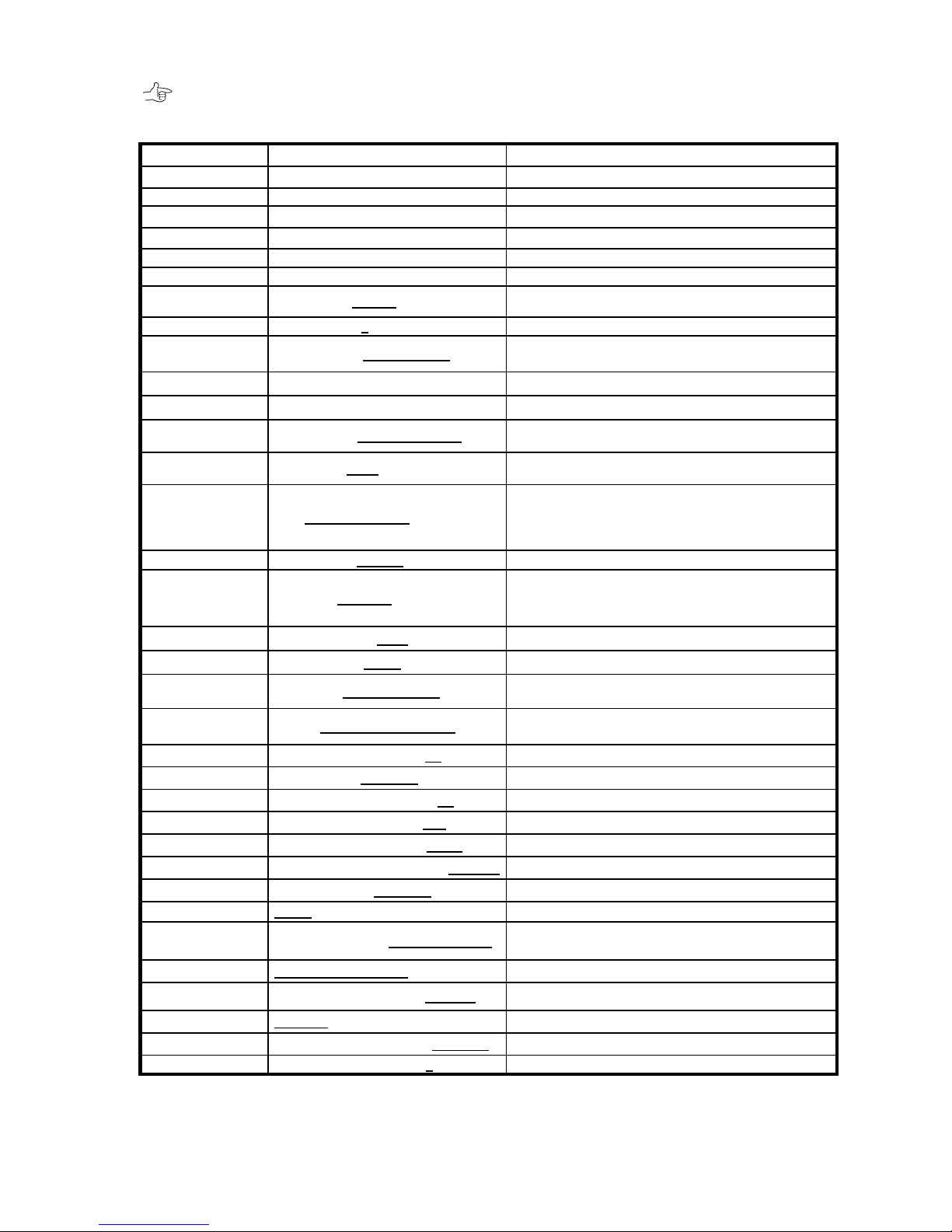
< Factory Default Setting >
This is a convenient form for customer to record all parameters.
Parameter
Default
Notes
Firmware
Firm ware is Ver. x.xxx
Firmware Version
Vendor ID
Vender ID is BIOS
Model No
Product ID is BR256B3-xxx6
Vary as different model
Serial No
Serial No ID xxxxxxxx
Product serial number
SATA HOST
Enable
Enable or disable eSATA
USB3 HOST
Enable
Enable or disable USB3
Raid Mode
RAID MODE RAID-6
SINGLE DRIVE / RAID-1 / RAID-0 2 / RAID-1 3 /
RAID-10 / RAID-6 / RAID-0 / RAID-3 / RAID-5
Drive Mode
DRIVE MODE 6
3 / 4 / 5 / 6
eSATA Speed
Host 3.0Gbps SSC RCV Cap
1.5Gbps SSC RCV Cap, 1.5Gbps No SSC RCV Cap,
3.0Gbps SSC RCV Cap, 3.0Gbps No SSC RCV Cap
USB2 Port
Enabled
Enabled or Disabled
FLUSH CACHE
Ignore FLUSH CACHE
Ignore or Enable
Max Disk Sync
Disk 1.5Gbps No SSC Rcv Cap
1.5Gbps SSC RCV Cap, 1.5Gbps No SSC RCV Cap,
3.0Gbps SSC RCV Cap, 3.0Gbps No SSC RCV Cap
Disk Type
DISK TYPE xxxB
TEST1GB, 120GB, 160GB, 250GB, 400GB, 500GB,
750GB, 1TB, 2TB, 3TB, 4TB
LUN MODE
LUN DIRECT No BIAS
DIRECT No BIAS / SWAPPED No BIAS /
DIRECT for MBR(-1) / SWAPPED for MBR(-1) /
DIRECT for MBR(+1) / SWAPPED for MBR(+1) /
DIRECT for MBR(-2) / SWAPPED for MBR(-2)
Cache Size
CACHE SIZE 128 MB
64 MB / 128MB
LUN Size
LUN SIZE Max 2TB
FULL / 16GB / 32GB / 64GB / 128GB / 256GB / 1/2 /1/3 /1/4 /
1/5 / 1/6 / 1/7 / 1/8 / 64GB+ALL / 64GB+MAX2TB /Max 2TB,
Max 2TB/2, Max 2TB/3, Max 2TB/4
Parity Stripe
PARITY STRIPE 2 MB/DRIVE
2 MB / 1 MB / 256 KB / 128 KB
Read Ahead
READ AHEAD 64 KB
0 KB / 8 KB / 64 KB / 256 KB / 1 MB / 4 MB
Recover RATE
RECOVER RATE 5Min./GB
TIME 0Sec / TIME 0.1Sec / TIME 1Sec / TIME 10Sec/
2Min./GB / 5Min./GB / 10Min./GB / 20Min./GB
Write Mode
WRITE ALL PENDING 0.1Sec
WAITING / BUFFERD / PENDING 0.1Sec / 1 Sec /
ALL PENDING 0.1Sec / 1Sec
Retry Time
RETRY MAXIMUM TIME 5S
25S / 10S / 5S / 1S / 0.3S
DPO/FUA
DPO/FUA BIT DISABLE
ENABLE / DISABLE
Check Delay
CHECK DRV DELAY TIME 1S
NONE / 0.1S / 0.5S / 1S / 5S
Power On Wait
WAIT POWER ON TIME 10S
1S / 5S / 10S / 15S / 20S
Wait Ready
HDD WAIT READY TIME 1 MIN
1 MIN / 3 MIN / 5 MIN
Sequential Ahead
SEQUENTIAL READ AHEAD 8 TIMES
8 TIMES / 16 TIMES / 32 TIMES / 2 TIMES / 4 TIMES
Check Cache
CHECK CACHE NORMAL
NORMAL / FAST / NO
Auto Patrol
AUTO HDD PATROL
AUTO / NO
Patrol Wait Time
SYSTEM PATROL 30 DAYS/CYCLE
WAIT 10S / 5S / 3S /
5 / 10 / 20 / 30 DAYS/CYCLE
Write Retry
WRITE RETRY MODE
NO WRITE RETRY / WRITE RETRY
Back Write Size
WRITE BACK MAX SIZE 4MB/CH
64KB / 128KB / 256KB / 512KB / 1MB / 2MB / 4MB
Parity
ENABLE PARITY
ENABLE / DISABALE
Buffer Segment
BUFFER SEGMENT SIZE 64KB/CH
8KB/CH / 16KB/CH / 32KB/CH / 64KB/CH
Sequential List
SEQUENTIAL LIST SIZE 8
8 / 16 / 32 / 64
Page 43
BR256(eSATA+USB3.0)model User Manual
- 42 -
Verify Wait
VERIFY WAIT READ aft WRITE
VERIFY WAIT READ aft WRITE /
VERIFY WAIT NO READ aft WRT /
NO VERIFY READ aft WRITE /
NO VERIFY NO READ aft WRITE
Page 44
BIOS CORPORATION
- 43 -
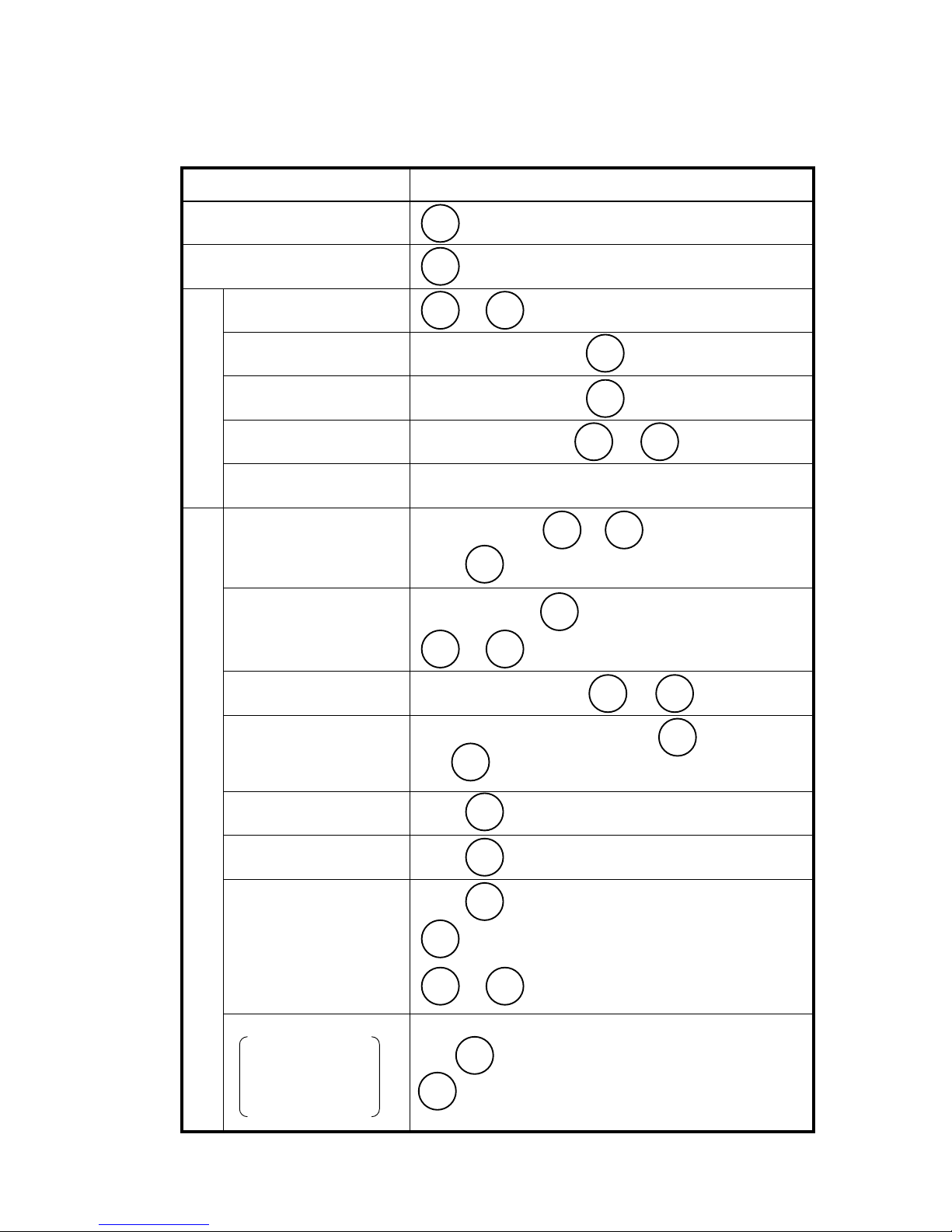
Quick Overview of From Panel Button Operation
BR256 button operations can be summarized as below
Item
Operation
Force Reset
+ Power ON
Mute Buzzer
Parameter Setup
Start
+ + Power ON
Roll next item
After parameter setup
Change the setting
After parameter setup
Write the setting
After parameter setup +
Cancel the change
Power Off during the parameter change
Status Information
Browse Parameters
During operation +
Press to roll to next parameters
Check Error Status
During operation
+ escape
Cancel RETRY display
During operation, press + twice
Performance information
Under Browsing Parameters, press
Use to check each drive
Cache Memory
Confirmation
Press after Performance Information
Slow Drive Confirmation
Press after Cache Memory Confirmation
PATROL Mode Change
(Auto、Force、No)
Press after host performance confirmation
: switch among settings
+ to set the change
Address Confirmation
Press after PATROL Mode Change
to check each address
MODE MODE
SELECT
MODE MODE
SELECT
MODE
SELECT
MAC Address →
IP Address →
Address Mask →
Gate Way Address
MODE
SELECT
MODE
SELECT
MODE
SELECT
MODE
SELECT
SELECT
MODE MODE
MODE MODE
SELECT
MODE
SELECT
MODE
MODE
Page 45

BR256(eSATA+USB3.0)model User Manual
- 44 -
2.6 Web-based Monitor and Setup via Ethernet
To monitor BR256 via Web management GUI, you can connect Ethernet cable to a host computer.
2.6.1 Web Connection
To use Web management, Ethernet parameter must be configured correctly before launching a Web
browser (such as Internet Explorer). For IP Address configuration, please follow steps below.
● Parameter Setup Mode
First press MODE and SELECT button at power on BR256. The system will enter Parameter Setup
mode as shown on LCD display.
● IP Address Setup
Press SELECT then MODE; it will enter IP address setup parameter.
Use SELECT button to change the number and MODE to switch to next field.
Hold SELECT button then number will rise faster.
After setting up, press MODE and SELECT at the same to save the change
Before the Save operations, the IP address will not be changed.
The new IP address will be effective after system reboot.
● Default IP address
The default IP address of the product is 192.168.50.210
ARRAY PARAMETERS
SETTING
IP Address
192.168. 50.210
POWER DOWN
PLEASE!
Page 46
BIOS CORPORATION
- 45 -
2.6.2 Main Menu
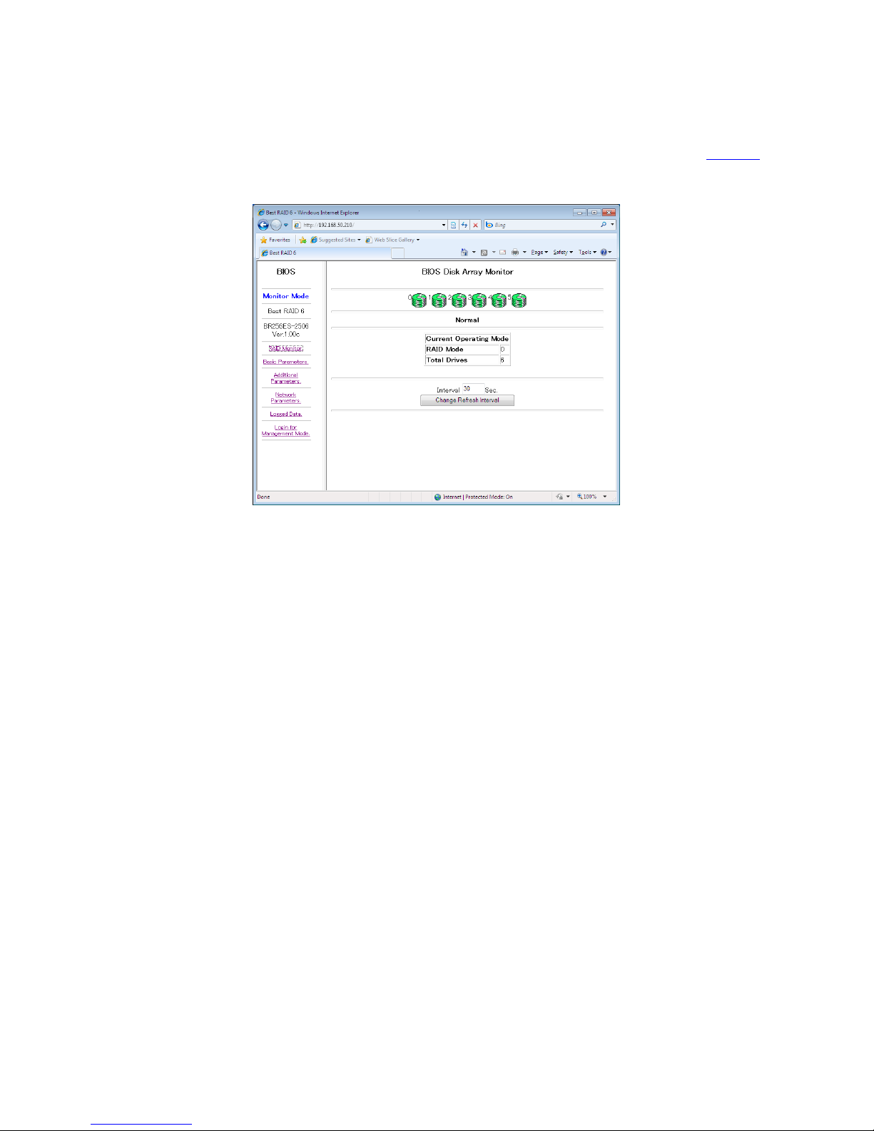
With power on and Ethernet connected, launch the Internet browser with preset IP address.「http://<IP
Address>」. The Web main menu will be displayed as below for Monitor Mode.
Page 47
BR256(eSATA+USB3.0)model User Manual
- 46 -
2.6.3 Monitor Mode
Disk Array Monitor:
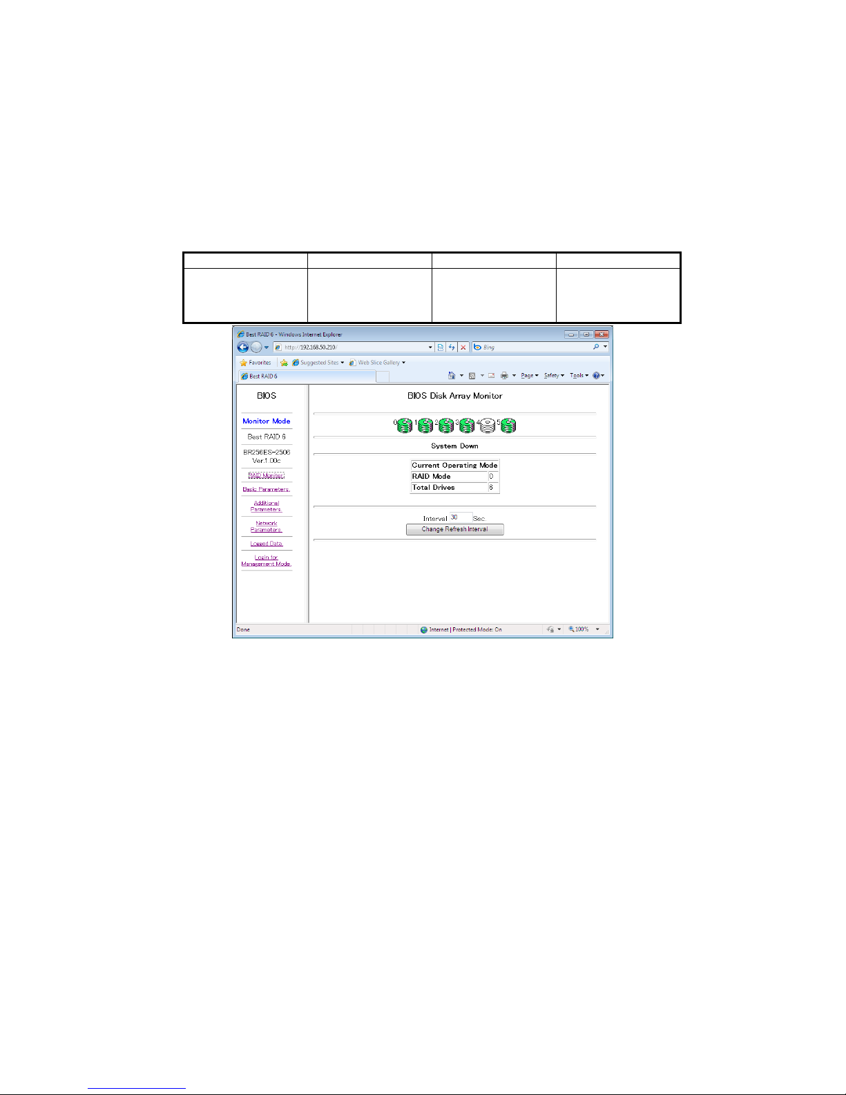
Click on [RAID Monitor] from left main menu to enter the status monitor page. The refreshing interval can be
changed by specifying the requested time and apply Change Refresh Interval.
Drive status can be differentiated by color.
Green
Red
Yellow
White
Normal
One Down
Two Down
System Down
Recovering
Verifying
Not installed
RAID parameters cannot be changed but shown under Monitor mode
Page 48
BIOS CORPORATION
- 47 -
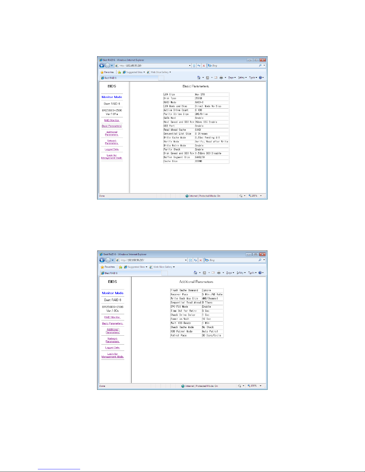
<Basic Parameters>
Click on menu [Basic Parameters] to show basic RAID parameters.
<Basic parameter screen>
<Additional Parameters >
Click on menu [Additional Parameters] to show additional RAID parameters.
<Additional RAID parameters>
Page 49
BR256(eSATA+USB3.0)model User Manual
- 48 -
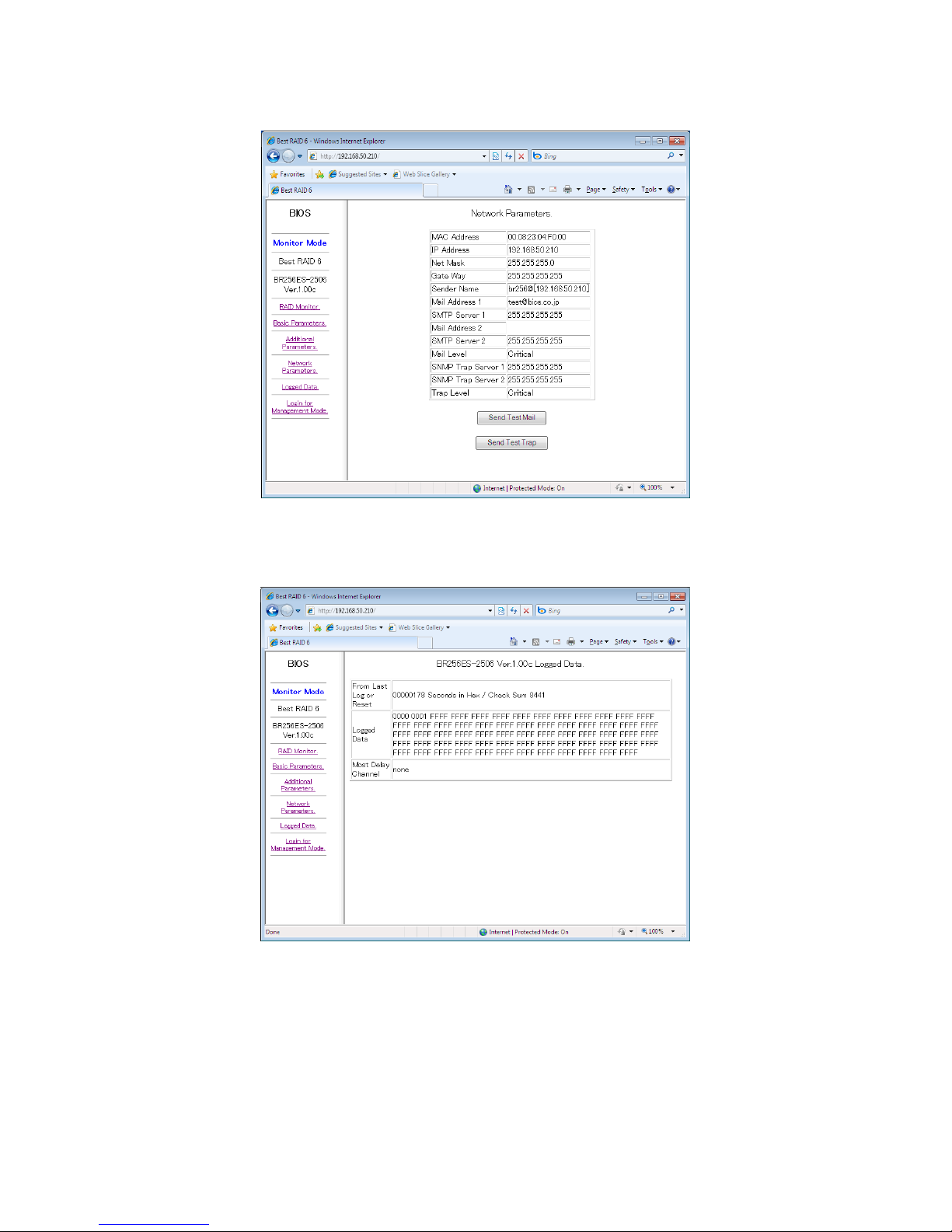
<Network Parameters>
Click on menu [Network Parameters] to show Network related parameters.
<Network related parameters screen>
<Logged Data>
Click on menu [Logged Data] to show Logged Data.
<Logged data screen>
Logged data shows the historic events after power on.
First item on top of the log table shows either the lapsed time of last log or the lapsed time after power on.
Time is shown in Second by hexadecimal. The checksum value on its right hand side is only for firmware
identification. It varies per firmware version.
The next number indicates the sequence of Log. The last log is right before number FFFF.
The number 0020~0022 has special meaning for email notification error. See below explanation.
Page 50
BIOS CORPORATION
- 49 -
2.6.4 Management Mode
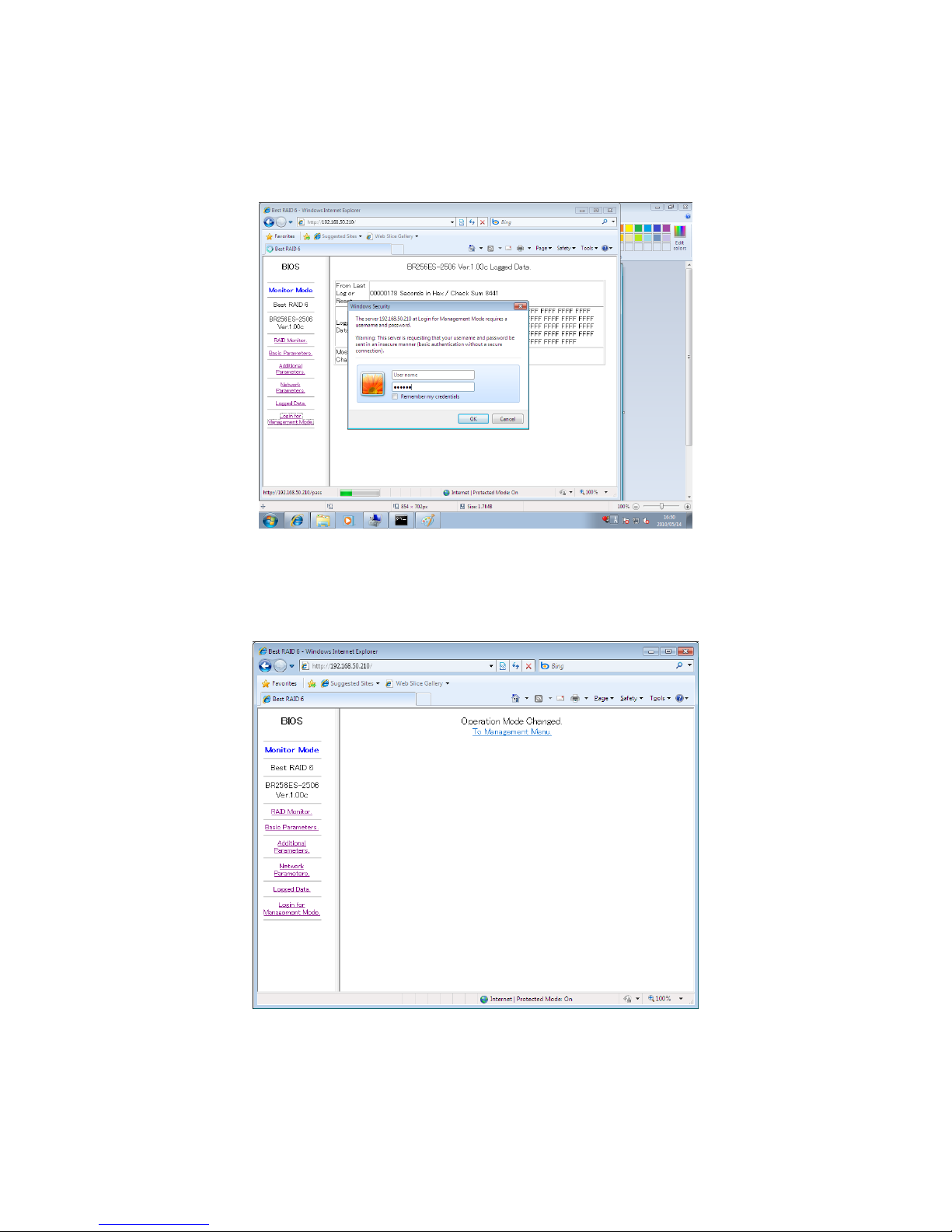
To modify additional parameters of RAID control or SMPT email setup, you need to login to secured
management mode.
Click [Login for Management Mode] from main menu.
<Pop window for User Name/Password to enter Management mode>
Default password is”passwd” and leave user name as empty
▶ To change password, refer to 2.7 Setup <Change Password>
<Page shown for changing to Management mode>
Switch to Management Mode buy clicking on [To Management Menu] when Operation Mode Changed is pop
Page 51
BR256(eSATA+USB3.0)model User Manual
- 50 -
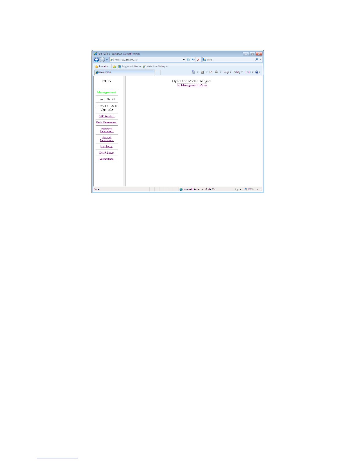
up.
<Page indicates Management mode>
You can then modify additional RAID parameters, email and SMTP setting.
Page 52
BIOS CORPORATION
- 51 -
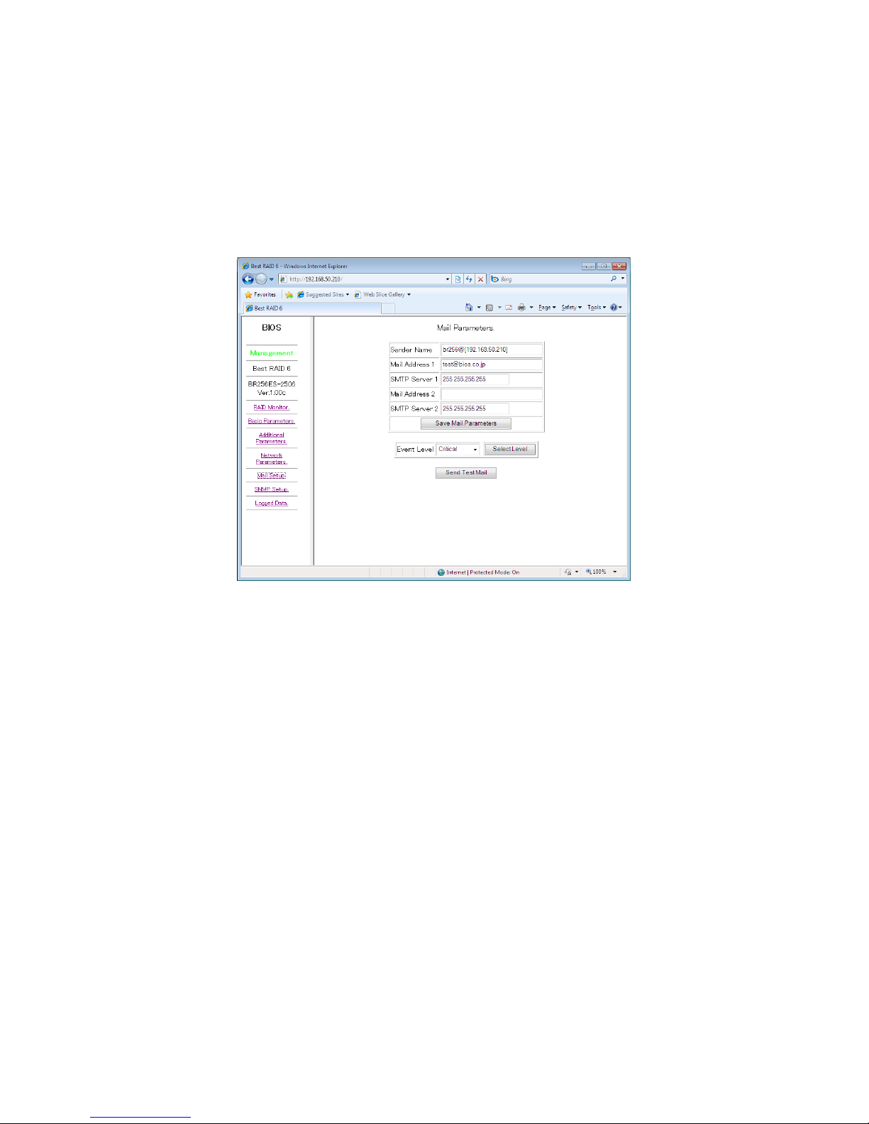
2.6.5 Setup of email notification
<Mail Setup> Mail Setup
It allows you to change email sending parameters and send a test email.
It is necessary to login to Management Mode or Setup Mode before you can make the change.
Click on [Mail Setup] from the main menu.
<Page for setup mail parameters>
● Sender Address [email protected]
Up to 63byte alphabet, number, “_”, “-“, “@”, and “.” is allowed. Two byte characters such as Chinese
are not allowed.
● Receiver Address [email protected]
Up to two receivers address are allowed.
For users who want to have more than 2 receivers, you need to setup alias on assigned email server.
Allowable characters are same as Sender address.
● SMTP Server Address 255.255.255.255
Setup IP Address of SMTP server.
IP of 255.255.255.255 will prohibit emails to be sent out.
1)Directly setup the IP to SMTP server
This is most effective way to issue email alert. However Gateway address might be necessary if
SMPT server is not within the same LAN. (see Basic Parameter, Setup page) At the same time,
this will expose the BR256 accessible from outside of LAN. This might cause the security issue.
2)Assign local SMTP Server
If there is no need for authentication, you can forward (relay) from BR256 by setting up the local
SMPT server. For Windows OS, you can setup IP address of BR256 on SMPT which has the
RELAY function.
● Send Test Mail (button)
Page 53
BR256(eSATA+USB3.0)model User Manual
- 52 -
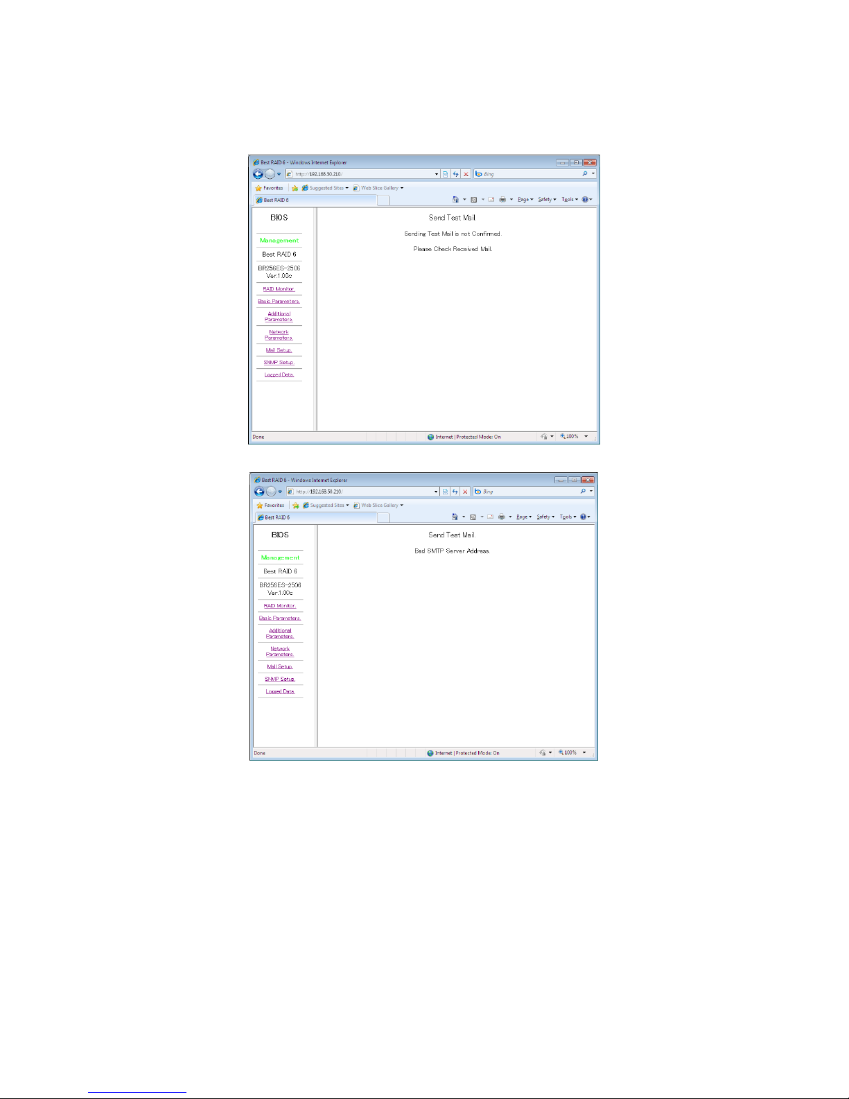
By clicking on “Send Test Main” button following the email setup, you can send a test email to the
receiver address for confirmation. To send a test email, you have to login to Management mode, but
no need to be in Setup Mode.
<A successful screen>
<A failed screen>
There will be “Sending Test Mail” shown on the screen indicating the email in transmission. And the
log will record a message if the test mail was sent out. Possible error code if the Send Test Main failed
after retried.
0020: SMTP was not found
0021: Gateway was not found
0022: SMTP did not respond
It might take up to 10 mins for the retrial if the mail could not be sent.
There might be cases which SMTP did respond but with wrong answer. We suggest trying a different
SMTP server under such situation.
Page 54

BIOS CORPORATION
- 53 -
2.6.6 Mail Format
The mail format will be looked like below:
From: BR256@[192.168.50.210]
To: [email protected]
Subject: Alert from BR256
Alert Condition of BIOS BR256xx-xxx6 Ver.x.xxx
Serial Number= xxxxxxxx
Alert Reason = Test of Send Mail.
1) From: Mail sender, this machine
2)To: Receiver
3)Subject:
4)Alert Condition of vendor name, device name, and version.
5)Serial Number: the serial number of this device
6)Alert Reason: Cause of this email sent
2.6.7 Conditions of Mail Notification
Under below conditions, the mail will be sent:
1)Drive failure One Drive Down
Two Drives Down
System Down
2)Completion of Drive Recovery Recover Finished
3)System Power Off Power Unit Down
4)Fan is failed Fan Unit Down
If the event was remained, the same email will be sent again upon the power recycling. If there are more
than two events happened at the same time, only the first one will be sent.
Page 55
BR256(eSATA+USB3.0)model User Manual
- 54 -
2.7 Setup
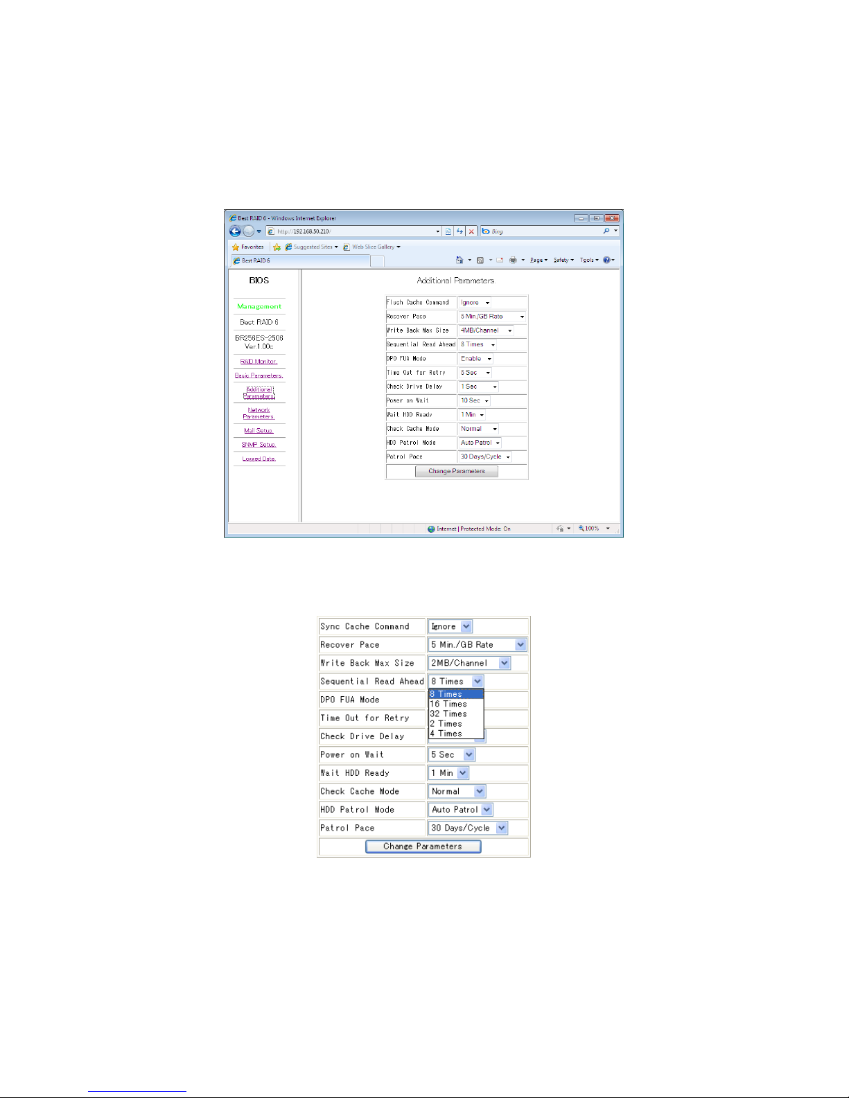
< Additional Parameters >
In Management Mode, click Additional Parameters under main menu to enter Additional Parameters Page
<Additional Parameters Page>
Parameter settings under additional parameters can be changed without effecting data on the RAID system.
Scroll to the parameter value you wish to change then click Change Parameters button to save the change.
Page 56
BIOS CORPORATION
- 55 -
● Setup Mode
First, Power on the RAID system while holding both MODE and SELECT buttons to enter Setup Mode.
( LCD Display: ARRAY PARAMETERS SETTING )
Launch the web browser with preset IP Address to connect to the management GUI. The default IP
address is 192.168.50.210
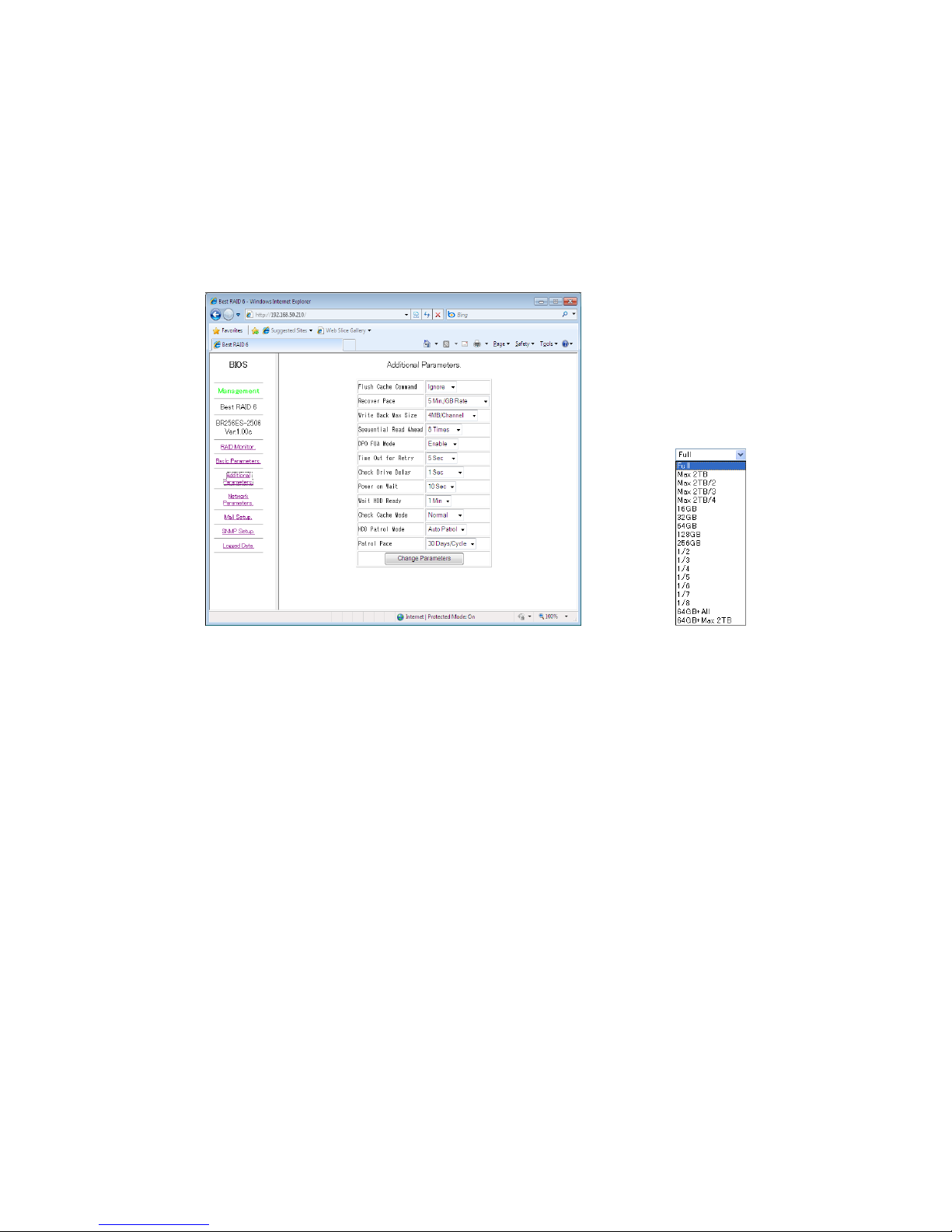
<Critical Parameters>
Click on Critical Parameters under main menu to enter Critical Parameters page.
<Critical Parameters Page> <Parameter Example: LUN Size>
Scroll to the parameter that is needed to changed and click Change Parameters button to save it. Then,
re-boot the RAID system so changes will be reflected.
Warnings
Change of any critical parameters will result whole data loss. After change, it is required to re-create
new partition and formatting process.
Page 57
BR256(eSATA+USB3.0)model User Manual
- 56 -
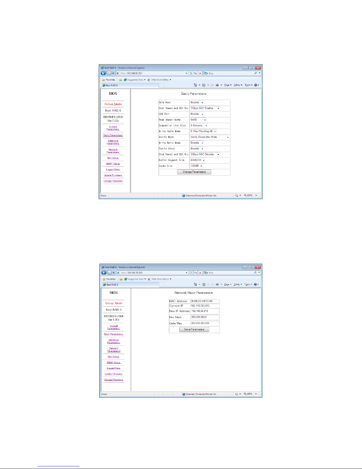
<Basic Parameters>
Click on Basic Parameters under left panel to enter Basic Parameters page.
<Basic Parameters Page>
Scroll to the parameter that is needed to changed and click Change Parameters button to save it. Then,
re-boot the RAID system so changes to reflected.
<Network Parameters>
Click on Network Parameters under left panel to enter Network Parameters page.
<Network Parameters Page>
After entering correct network information, click Save Parameters button to save it. Then, re-boot the RAID
system so changes to reflected.
Page 58
BIOS CORPORATION
- 57 -
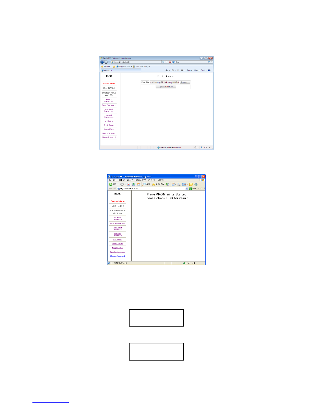
<Update Firmware>
Click on Update Firmware under left panel to enter Update Firmware page.
Navigate through file system to locate firmware file and click update firmware button to start update
process.
Once update process has started, front LCD display will change to following message.
<BR256 LCD Display>
Please Wait!
Firm Updating
Firmware is being updated
Power off Now!
Firm Update OK
Update complete Please Reboot the system.
Page 59
BR256(eSATA+USB3.0)model User Manual
- 58 -
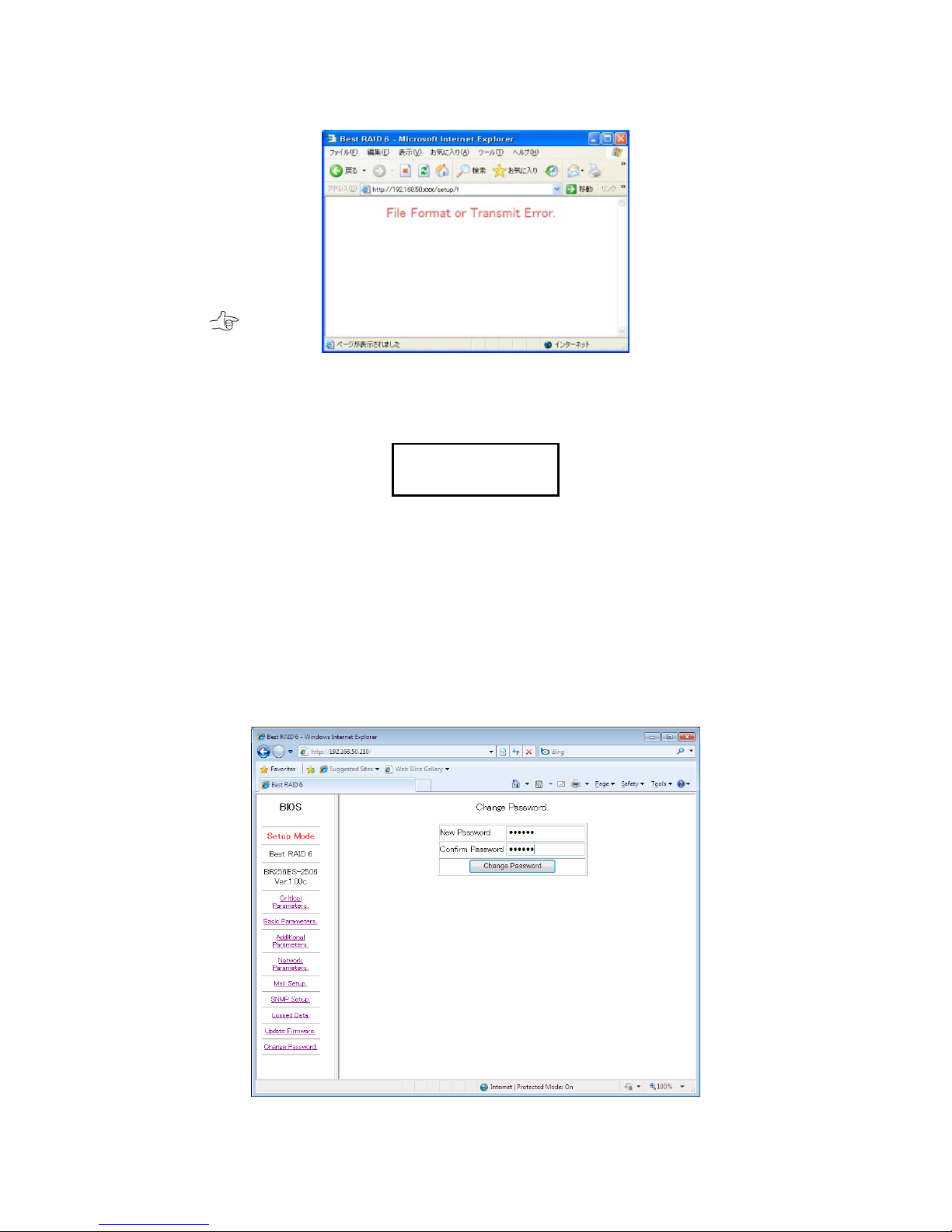
If the process failed the following screen will be shown.
<Wrong firmware file or transmission error>
<BR256 LCD Display>
Error has occurred during the process.
Warning!!
Do not turn off RAID system at this point. Instead, retry without rebooting the system. If the
process still failed, please contact support people.
<Change Password>
In Setup Mode, click Change Password under main menu to enter Change Password page. This allows
you to change the password for logging into “Management Mode”.
<Change Password Page>
Error Retry Now!
Don’t Power off
Page 60
BIOS CORPORATION
- 59 -
1)Enter new password in New Password and Confirm Password box. (Max 6 digits)
2)Click Change Password button to save the change
Reboot the RAID system for change to take effect.
What if I forgot my password?
Old password is not needed to change the password itself, so just change to new password.
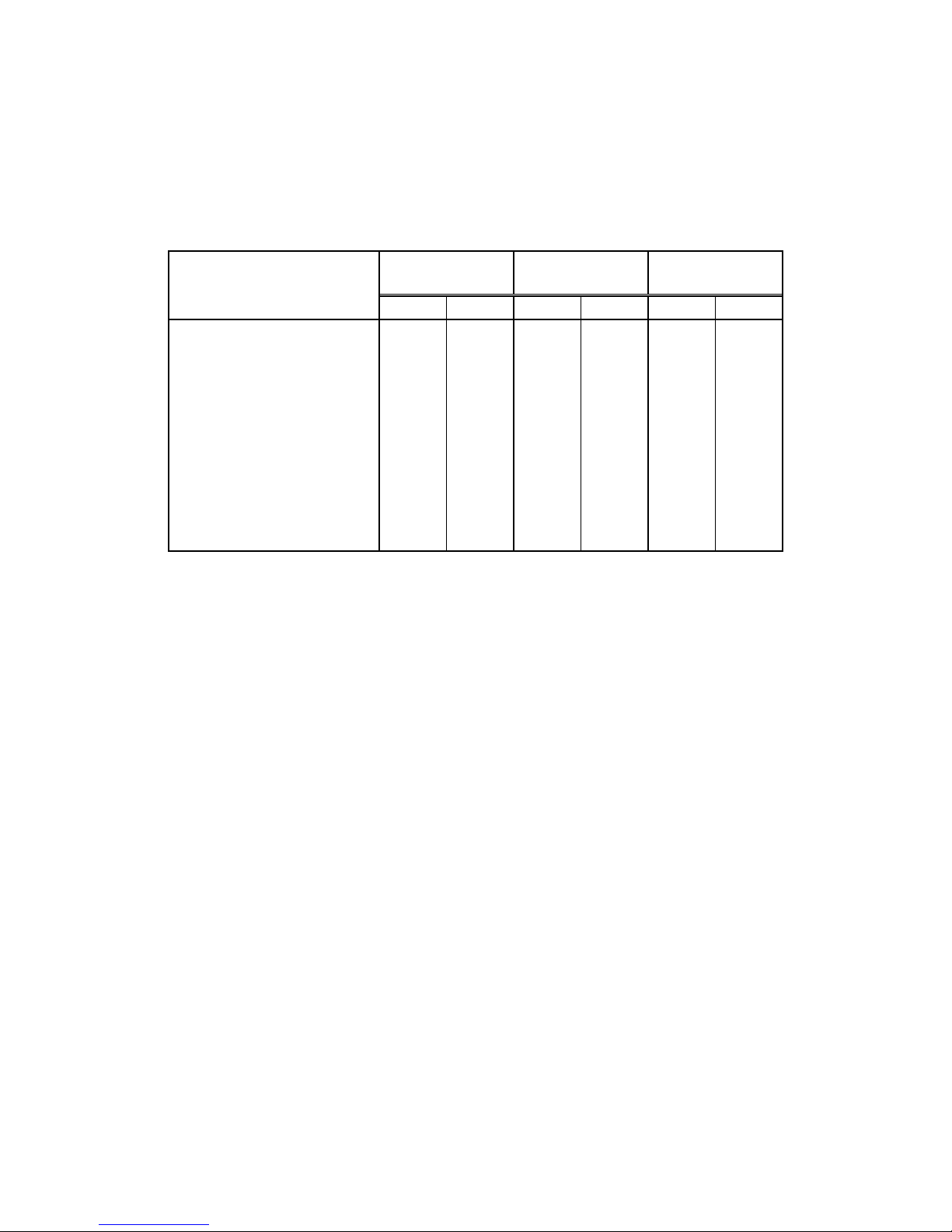
● Available functions for each Mode with WEB GUI
Menu
Monitor Mode
Management
Mode
Setup Mode
Read
Modify
Read
Modify
Read
Modify
RAID Monitor
O X O X X X Basic Parameters
O X O X O O Additional Parameters
O X O O O O Critical Parameters
X X X X O O Network Parameters
O X O X O
O
Mail Setup
X X O O O
O
SNMP Setup
X X O O O O Logged Data
O X O X O X Update Firmware
X X X X O
O
Login for Management Mode
O O X X X X Change Password
X X X X O
O
Read:You can see the items
Modify:You can modify the parameters or executes the operation.
Page 61
BR256(eSATA+USB3.0)model User Manual
- 60 -
2.8 Host LAN Configuration
2.8.1 IP Setup for Windows
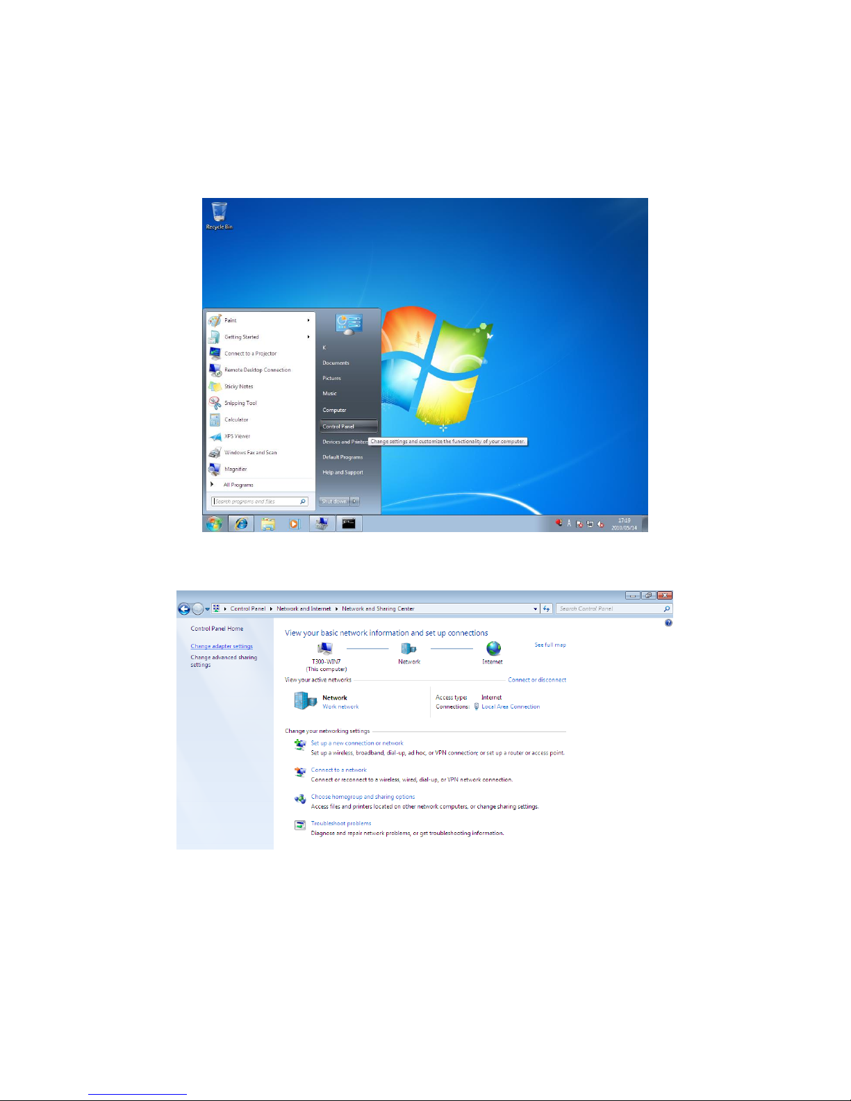
1.Go to: Start -> Control Panel
2.Navigate to Network and Internet -> Network and Sharing Center
Page 62
BIOS CORPORATION
- 61 -
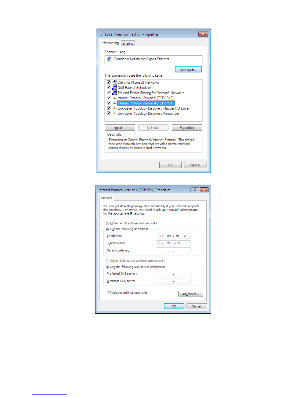
3. Choose Internet Protocol Version 4(TCP/Ipv4) then click Properties button.
4.Set Internet Protocol Properties
First, check “use the following IO address”. Considering RAID IP ADDRESS is 192.168.50.210 set
as follows:
IP address: 192.168.50.XXX (put unused address in place of XXX.)
Subnet mask: 255.255.255.0
Then, click OK button.
Make sure the IP address used here is not used by another device, or it may not work properly.
Page 63
BR256(eSATA+USB3.0)model User Manual
- 62 -
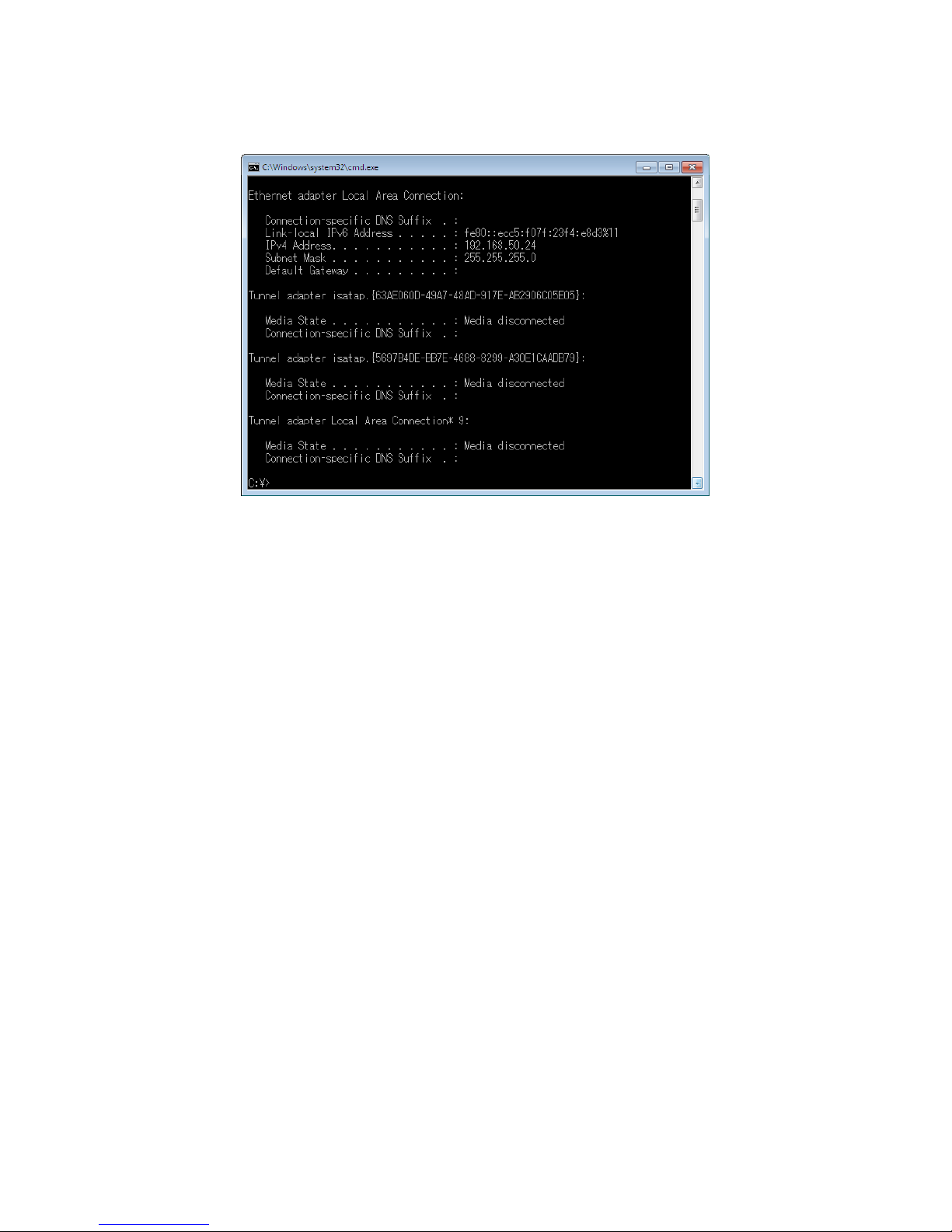
5.Confirming the change
1.Start -> enter “cmd.exe” to open command prompt window.
2.Enter ipconfig /renew 3.Enter ipconfig /all Check if the IP Address has changed
correctly.
2.8.2 IP Setup for Linux
1.Open a Terminal Window.
2.Enter # ifconfig eth0 192.168.50.X
(*Put IP that is not used in the current network in “X”.)
3.Enter $ sudo dhclient then press enter key.
4. Enter #ifconfig to confirm changed IP address
Page 64
BIOS CORPORATION
- 63 -
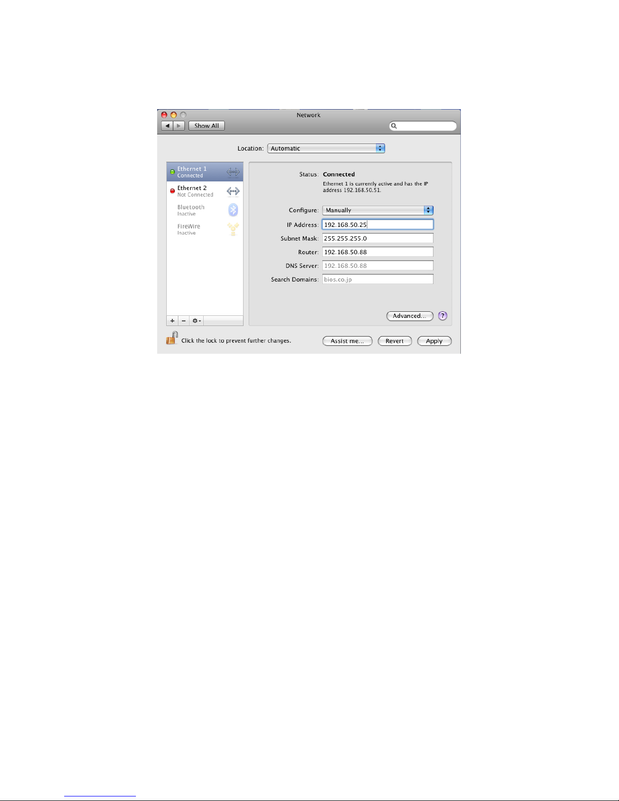
2.8.3 IP Setup for MAC OS X
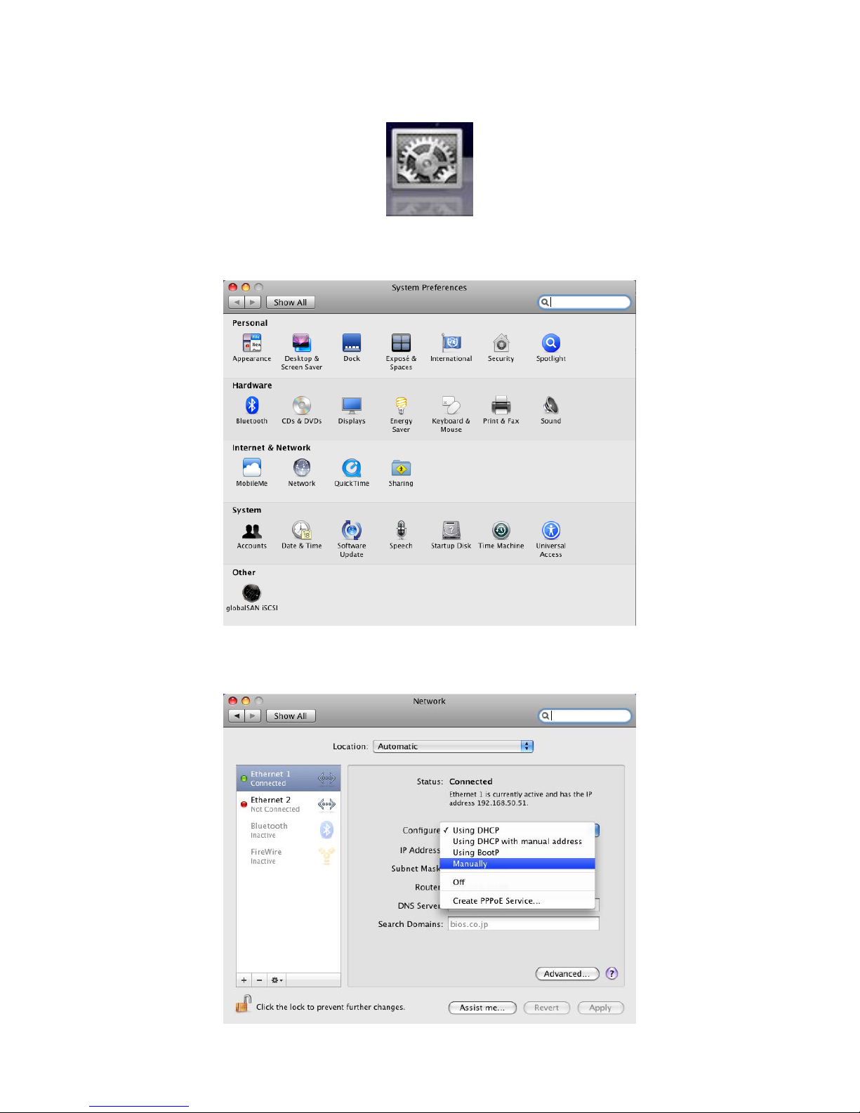
1. Click System Preferences.
2.Click “Network” Icon.
Page 65
BR256(eSATA+USB3.0)model User Manual
- 64 -
3.Choose Configure option to Manually.
4.Enter IP address and click Apply button to save it.
▶ Make sure the address used here is not used by another device.
Page 66

BIOS CORPORATION
- 65 -
‥‥‥‥‥‥‥‥‥‥‥‥‥‥‥‥‥‥‥‥‥‥‥‥‥‥‥‥‥‥‥‥‥‥‥‥‥‥‥‥‥‥‥‥‥‥‥‥
‥‥‥‥‥‥‥‥‥‥‥‥‥‥‥‥‥‥‥‥‥‥‥‥‥‥‥‥‥‥‥‥‥‥‥‥‥‥‥‥‥‥‥‥‥‥‥‥
‥‥‥‥‥‥‥‥‥‥‥‥‥‥‥‥‥‥‥‥‥‥‥‥‥‥‥‥‥‥‥‥‥‥‥‥‥‥‥‥‥‥‥‥‥‥‥‥
‥‥‥‥‥‥‥‥‥‥‥‥‥‥‥‥‥‥‥‥‥‥‥‥‥‥‥‥‥‥‥‥‥‥‥‥‥‥‥‥‥‥‥‥‥‥‥‥
‥‥‥‥‥‥‥‥‥‥‥‥‥‥‥‥‥‥‥‥‥‥‥‥‥‥‥‥‥‥‥‥‥‥‥‥‥‥‥‥‥‥‥‥‥‥‥‥
‥‥‥‥‥‥‥‥‥‥‥‥‥‥‥‥‥‥‥‥‥‥‥‥‥‥‥‥‥‥‥‥‥‥‥‥‥‥‥‥‥‥‥‥‥‥‥‥
‥‥‥‥‥‥‥‥‥‥‥‥‥‥‥‥‥‥‥‥‥‥‥‥‥‥‥‥‥‥‥‥‥‥‥‥‥‥‥‥‥‥‥‥‥‥‥‥
‥‥‥‥‥‥‥‥‥‥‥‥‥‥‥‥‥‥‥‥‥‥‥‥‥‥‥‥‥‥‥‥‥‥‥‥‥‥‥‥‥‥‥‥‥‥‥‥
‥‥‥‥‥‥‥‥‥‥‥‥‥‥‥‥‥‥‥‥‥‥‥‥‥‥‥‥‥‥‥‥‥‥‥‥‥‥‥‥‥‥‥‥‥‥‥‥
‥‥‥‥‥‥‥‥‥‥‥‥‥‥‥‥‥‥‥‥‥‥‥‥‥‥‥‥‥‥‥‥‥‥‥‥‥‥‥‥‥‥‥‥‥‥‥‥
‥‥‥‥‥‥‥‥‥‥‥‥‥‥‥‥‥‥‥‥‥‥‥‥‥‥‥‥‥‥‥‥‥‥‥‥‥‥‥‥‥‥‥‥‥‥‥‥
‥‥‥‥‥‥‥‥‥‥‥‥‥‥‥‥‥‥‥‥‥‥‥‥‥‥‥‥‥‥‥‥‥‥‥‥‥‥‥‥‥‥‥‥‥‥‥‥
‥‥‥‥‥‥‥‥‥‥‥‥‥‥‥‥‥‥‥‥‥‥‥‥‥‥‥‥‥‥‥‥‥‥‥‥‥‥‥‥‥‥‥‥‥‥‥‥
‥‥‥‥‥‥‥‥‥‥‥‥‥‥‥‥‥‥‥‥‥‥‥‥‥‥‥‥‥‥‥‥‥‥‥‥‥‥‥‥‥‥‥‥‥‥‥‥
‥‥‥‥‥‥‥‥‥‥‥‥‥‥‥‥‥‥‥‥‥‥‥‥‥‥‥‥‥‥‥‥‥‥‥‥‥‥‥‥‥‥‥‥‥‥‥‥
‥‥‥‥‥‥‥‥‥‥‥‥‥‥‥‥‥‥‥‥‥‥‥‥‥‥‥‥‥‥‥‥‥‥‥‥‥‥‥‥‥‥‥‥‥‥‥‥
‥‥‥‥‥‥‥‥‥‥‥‥‥‥‥‥‥‥‥‥‥‥‥‥‥‥‥‥‥‥‥‥‥‥‥‥‥‥‥‥‥‥‥‥‥‥‥‥
‥‥‥‥‥‥‥‥‥‥‥‥‥‥‥‥‥‥‥‥‥‥‥‥‥‥‥‥‥‥‥‥‥‥‥‥‥‥‥‥‥‥‥‥‥‥‥‥
‥‥‥‥‥‥‥‥‥‥‥‥‥‥‥‥‥‥‥‥‥‥‥‥‥‥‥‥‥‥‥‥‥‥‥‥‥‥‥‥‥‥‥‥‥‥‥‥
‥‥‥‥‥‥‥‥‥‥‥‥‥‥‥‥‥‥‥‥‥‥‥‥‥‥‥‥‥‥‥‥‥‥‥‥‥‥‥‥‥‥‥‥‥‥‥‥
‥‥‥‥‥‥‥‥‥‥‥‥‥‥‥‥‥‥‥‥‥‥‥‥‥‥‥‥‥‥‥‥‥‥‥‥‥‥‥‥‥‥‥‥‥‥‥‥
‥‥‥‥‥‥‥‥‥‥‥‥‥‥‥‥‥‥‥‥‥‥‥‥‥‥‥‥‥‥‥‥‥‥‥‥‥‥‥‥‥‥‥‥‥‥‥‥
‥‥‥‥‥‥‥‥‥‥‥‥‥‥‥‥‥‥‥‥‥‥‥‥‥‥‥‥‥‥‥‥‥‥‥‥‥‥‥‥‥‥‥‥‥‥‥‥
‥‥‥‥‥‥‥‥‥‥‥‥‥‥‥‥‥‥‥‥‥‥‥‥‥‥‥‥‥‥‥‥‥‥‥‥‥‥‥‥‥‥‥‥‥‥‥‥
‥‥‥‥‥‥‥‥‥‥‥‥‥‥‥‥‥‥‥‥‥‥‥‥‥‥‥‥‥‥‥‥‥‥‥‥‥‥‥‥‥‥‥‥‥‥‥
Page 67
BR256(eSATA+USB3.0)model User Manual
- 66 -
Chapter 3. Format
3.1 Linux
The section explains how to use with Linux for reference.
Please refer to Linux OS user guide for details.
1.Login as Superuser
Handling a disk is privileged function for Superuser only. Please login as a Superuser or a.k.a. “root”.
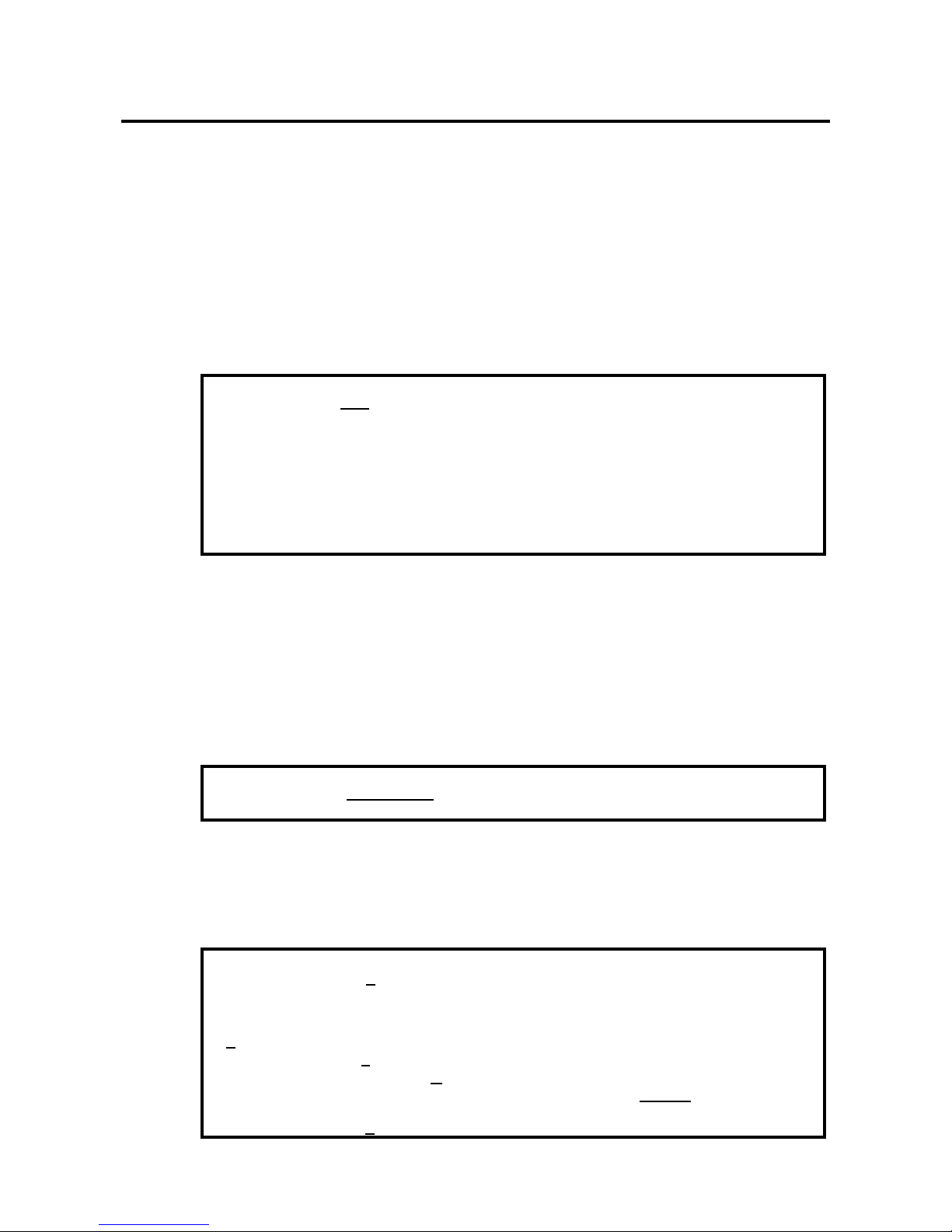
<Host name> login: root
Password:
******
Last login: XXX XXX XX XX:XX:XX
…
…
[root@<Host name> /root]#
2. Partition Creation and formatting (fdisk command)
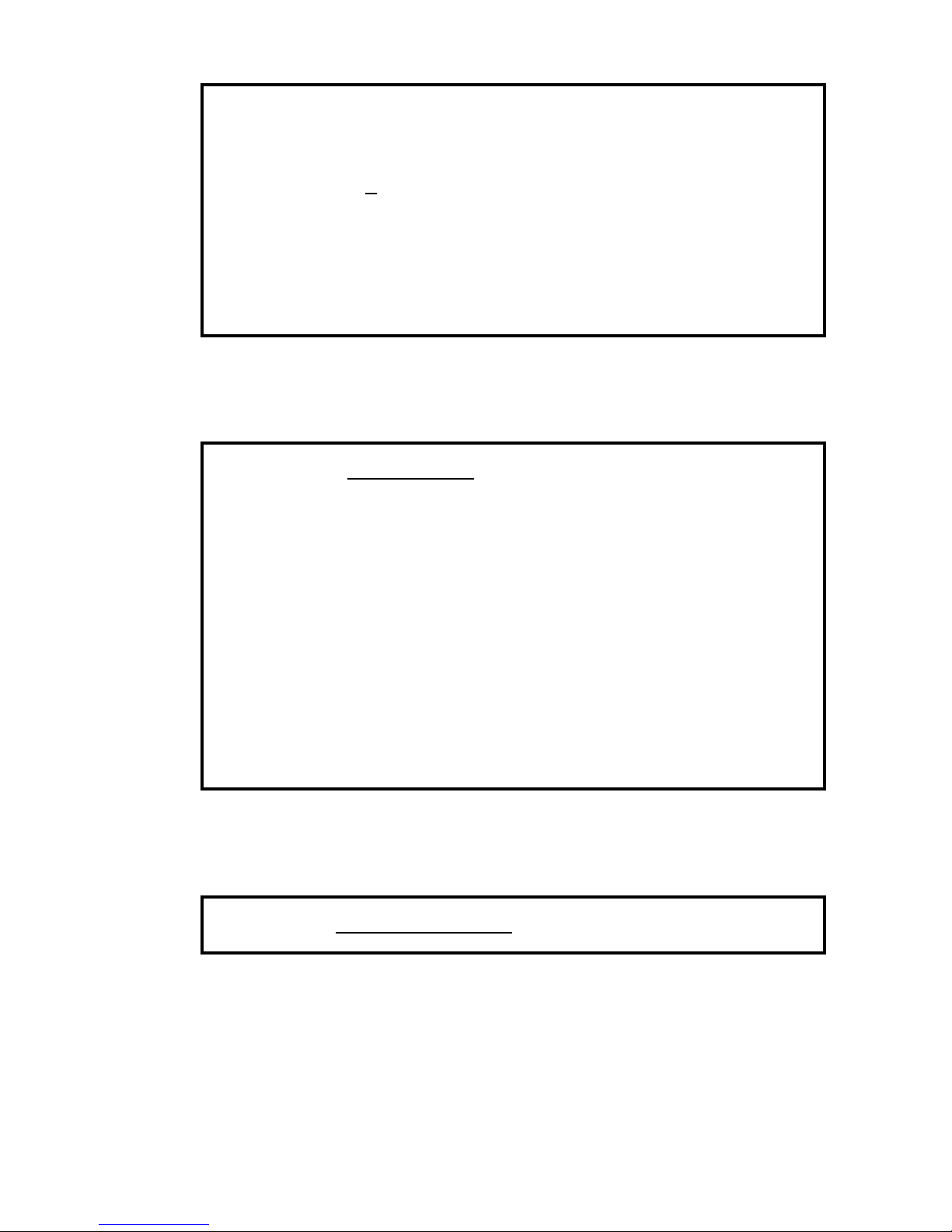
① start fdisk
*Example below is when BR256 is recognized as /dev/sdb
[root@sheep /root]# fdisk /dev/sdb
② Creating partition
*Example below is when creating one partition takes whole disk spaces
Command (m for help): n (n:fdisk のコマンド)
Command action
e extended
p primary partition (1-4)
p
Partition number (1-4): 1
First cylinder (1-182399, default 1): 1
Last cylinder or +size or +sizeM or +sizeK (1-182399, default 182399): 182399
Command (m for help): p (p:fdisk コマンド)
Page 68
BIOS CORPORATION
- 67 -
Disk /dev/sda: 255 heads, 63 sectors, 120130 cylindersUnits = cylinders of 16065 * 512 bytes
Device Boot Start End Blocks Id System
/dev/sda1 1 182399 1465119936 83 Linux
Command (m for help): w (w:fdisk コマンド)
The partition table has been altered!
Calling ioctl( ) to re-read partition table.
Syncing disks.
WARNING: If you have created or modified any DOS 6.x
partitions, please see the fdisk manual page for additional
information.
3. Formatting partition created (mke2fs command)
[root@sheep /root]# mke2fs /dev/sda1
mke2fs 1.29, 24-Sep-2002 for EXT2 FS 0.5b, 95/08/09
Filesystem label=
OS type:Linux
Block size=4096 (log=2)
Fragment size=4096 (log=2)
183140352 inodes, 366279984 blocks
18313999 blocks (5.00%) reserved for the super user
First data block=0
11178 block groups
32768 blocks per group, 32768 fragments per group
16384 inodes per group
Superblock backups stored on blocks:
32768, 98304, 163840, 229376, 294912, 819200, 884736, 1605632, 2654208,
4096000, 7962624, 11239424, 20480000, 23887872, 71663616, 78675968,
102400000, 214990848
Writing inode tables: done
Writing superblocks and filesystem accounting information: done
[root@sheep /root]#
4. Mounting File system
[root@sheep /root]#mount /dev/sdb1 /RAID
* “/dev/sdb1” is Device partition you are mounting and “/RAID” is the mount point.
Page 69
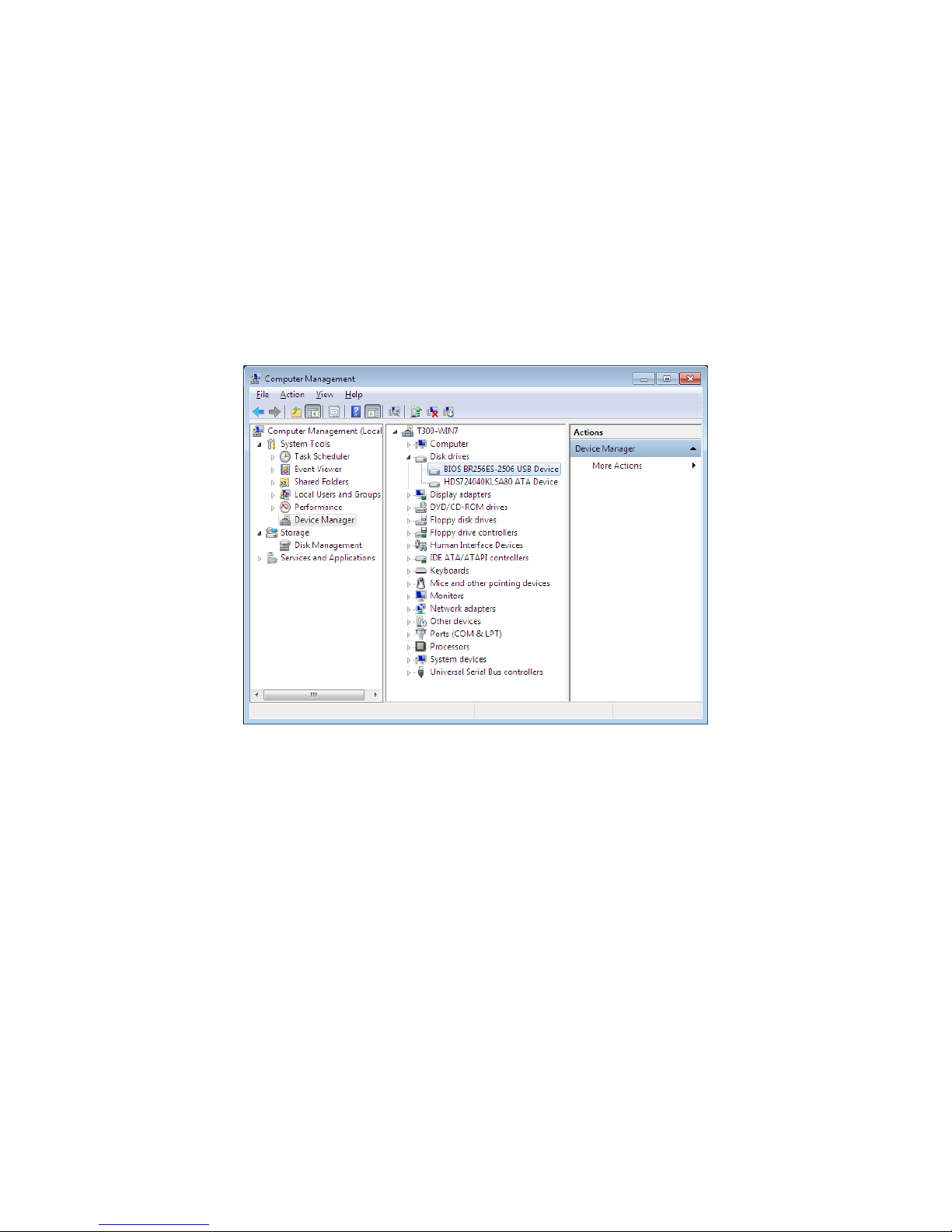
BR256(eSATA+USB3.0)model User Manual
- 68 -
3.2 Windows 7
The section explains how to use with Windows 7 for reference.
Please refer to Windows 7 user guide for details.
1. Confirm the connection
① Connect and power on BR256 then starts with host computer.
② Press the Start Button and right-click on “Computer”. Click on “Manage”.
③ Go to “Device Manager”. Click on Disk Drives and confirm that the BR256 has been registered.
※ If you did not see BR256 here, please check below
Is the host HBA recognized by OS or not? (Please consult with your HBA vendor if not)
Was BR256 normally started and connected?
Page 70
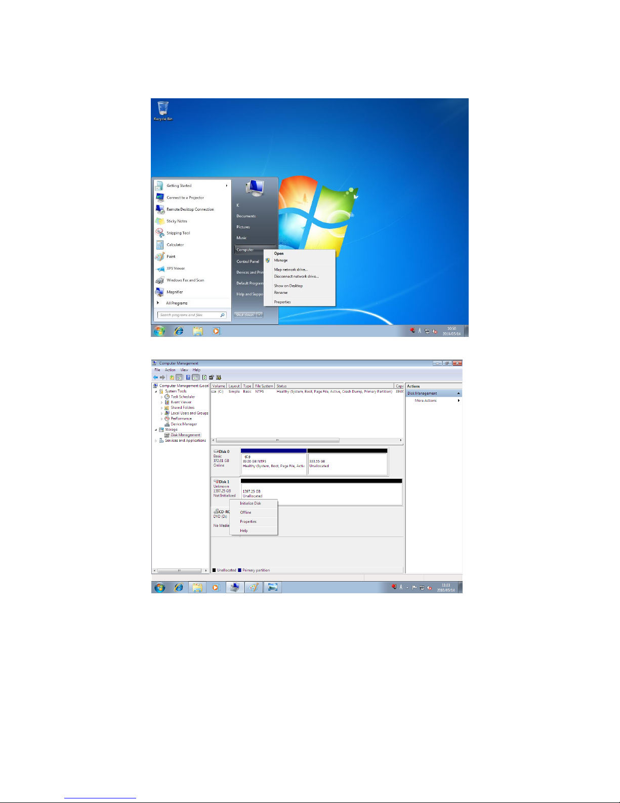
BIOS CORPORATION
- 69 -
2. Partition Creation and Formatting
1.Log into Windows 7 and click the Start, then right click on “Computer” and click on “Manage”
2. Click on “Computer Management” -> “Storage” -> “Disk Management”
3.Right click Not initialize disk(DISK1)then click「Initialize Disk」.
Page 71
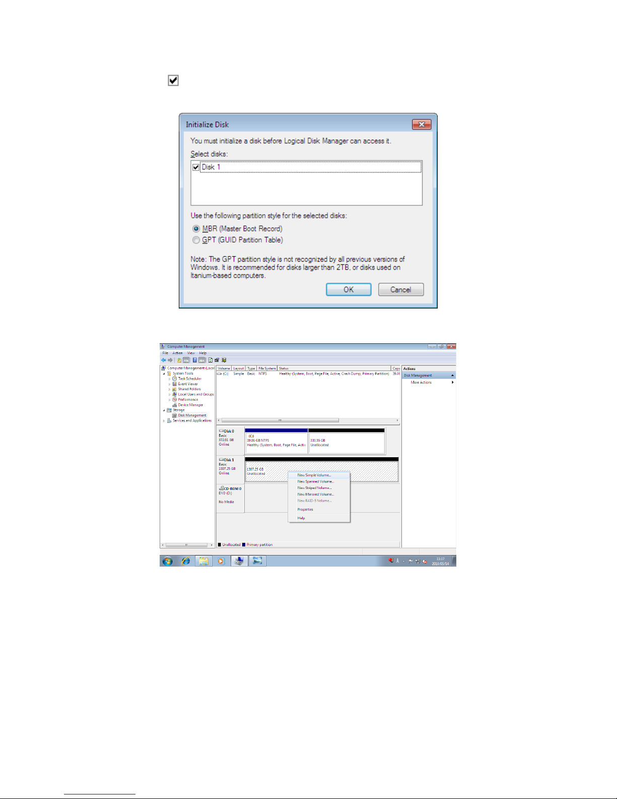
BR256(eSATA+USB3.0)model User Manual
- 70 -
4.Check the disk to be initialized and move on to the formatting.(If BR256 has capacity over 2TB in
Volume then choose GPT Disk label here to able to use disk over 2TB.)
5.Right click on the disk you wish to edit and click “New Simple Volume”
Page 72
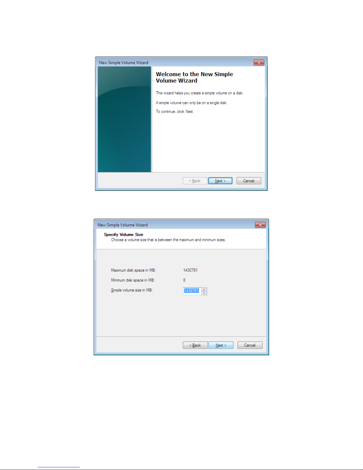
BIOS CORPORATION
- 71 -
6.The New Volume Wizard will load up, so click “Next”
7.Choose the volume you want, then click “Next”.
Page 73
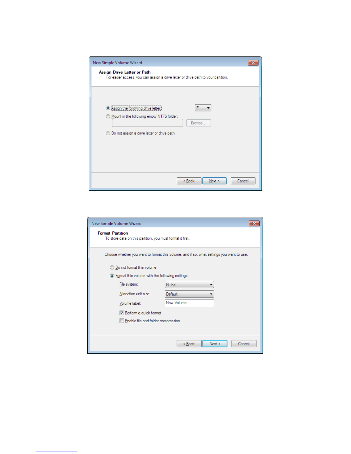
BR256(eSATA+USB3.0)model User Manual
- 72 -
8.Choose the driver letter you wish, click “Next”,
9.Choose the proper formatting settings and click “Next” again.
Page 74
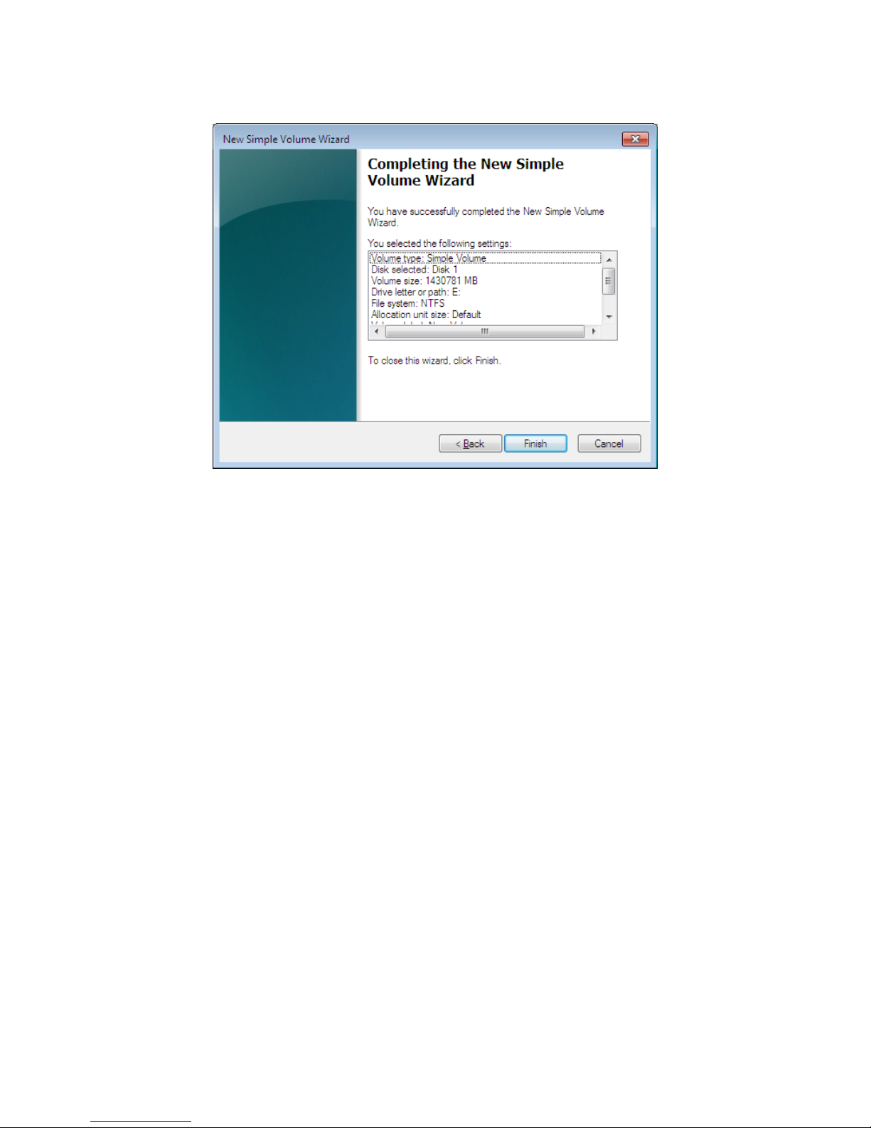
BIOS CORPORATION
- 73 -
10.When you’ve verified that the settings are correct and there are no errors, click “Finish”.
11.The format will begin.
Close the “Computer Management” after the format has completed.
※ You can use the disk now, please remember the disk name you made
Page 75

BR256(eSATA+USB3.0)model User Manual
- 74 -
3.3 Other OSs
Please refer to the user manual of associated vendors.
Page 76
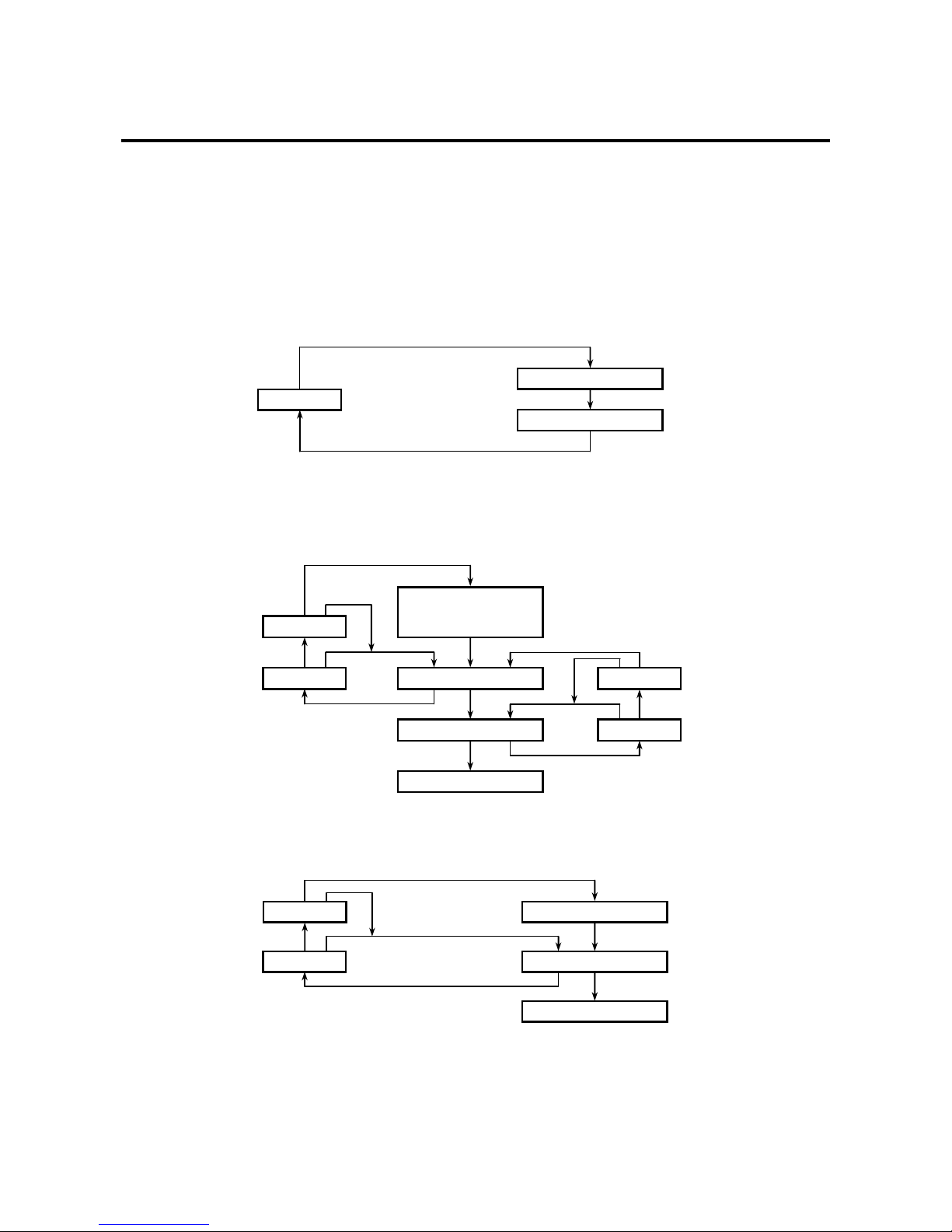
BIOS CORPORATION
- 75 -
RAID-0 NORMAL
SYSTEM DOWN
RESET
DOWN DRIVE
Chapter 4. BR256 State Transition
4.1 Overview of Disk Array State Transition
Any time the array transfers from NORMAL state to FAIL state, the alarm buzzer will sound, and the Fault
LED will light up. At this point, pressing the Mode button will stop the buzzer.
<RAID-0 State Transition>
<RAID- 6 State Transition>
<RAID- 3 / 5 State Transition>
OK END
RAID-6 NORMAL
ONE DOWN
DOWN DRIVE
SYSTEM DOWN
DOWN DRIVE
ERROR
REPLACE
RECOVER
TWO DOWN
VERIFY
RECOVER
VERIFY
REPLACE
OK END
ERROR
OK END
OK END
DOWN DRIVE
DOWN DRIVE
ERROR
REPLACE
RAID-x NORMAL
RECOVER
ONE DOWN
SYSTEM DOWN
DOWN DRIVE
VERIFY
OK END
OK END
Page 77

BR256(eSATA+USB3.0)model User Manual
- 76 -
Force Reset(Initialization)
If you force reset by powering on while holding down the MODE switch, all active drives will be returned
to their normal state. If all drives are active, the system will return to NORMAL. This should be applied
when it is the first time to initialize the disk array
At this time, the actual health of the disks will not be verified. All drives are assumed to be healthy.
If you would like to force reset right after [ONE DOWN] or [SYSTEM DOWN] reported, please follow
instruction of qualified technical support staff. While the array is in「ONE DOWN」or「SYSTEM DOWN」,
if you operate incorrectly, there might be chance to cause data corruption.
Force Reset(Transition from「SYSTEM DOWN」)
If there is a damaged drive, contact our technical support staff for further assistance.
Below is an example of typical operation
● After removing the damaged drive, hold the Mode switch at powering on and force reset the
machine. It will set up a most appropriate state for the unit
・DRIVE FAIL LED still on, means that drive was the first to go down. Please remove it first
・ DRIVE FAIL LED blinking, that drive went down afterwards so keep it installed. Hold down
the Mode switch and power cycle the machine for possible recovery
・ In a RAID-3/5 configuration, it will go back to ONE DRIVE DOWN status.
● It is sometimes possible to access the system even during SYSTEM DOWN.
Under such state, please try to access and backup data out of the array
● If nothing’s working, replace all the drives you think might be bad, and start over with a force
reset (Initialization).
Parity Drive
● Under RAID-3 configuration, Data drives and Parity drive are arranged in a sequential order.
Parity drive follows the last of data drive.
Page 78
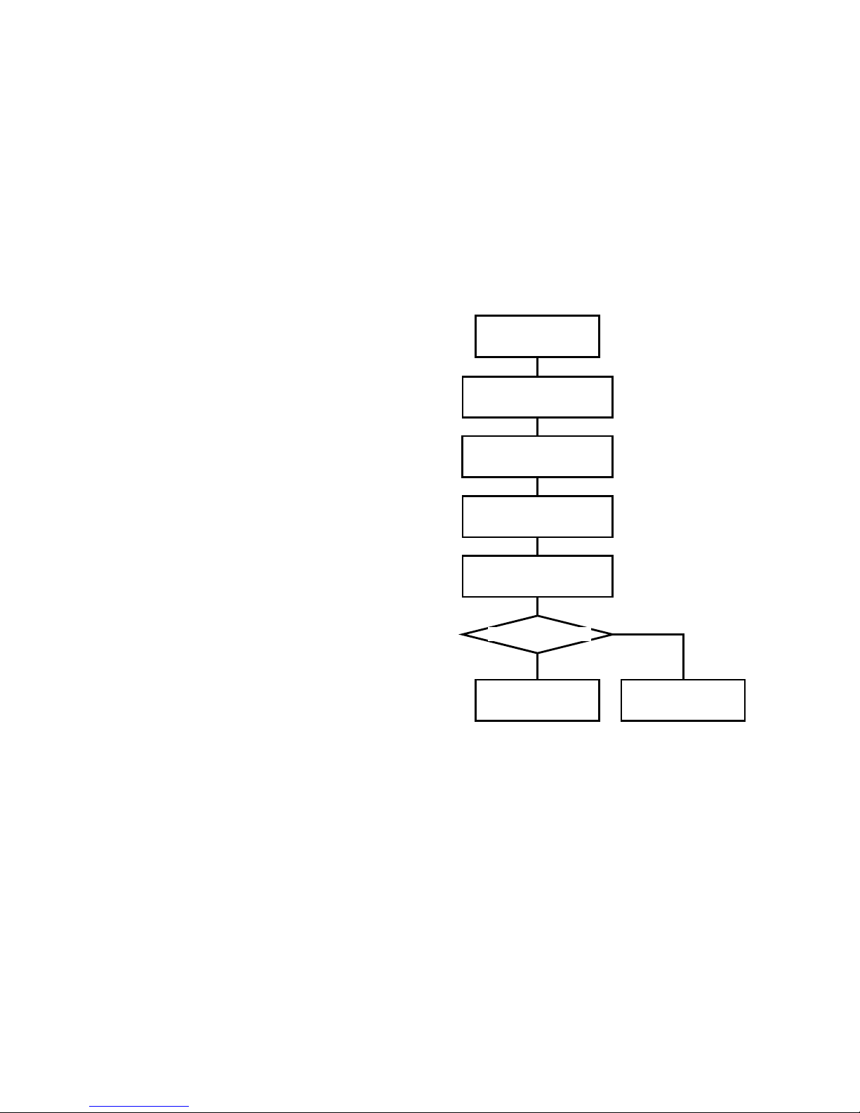
BIOS CORPORATION
- 77 -
4.2 Deal with 「ONE DRIVE DOWN」state
Under RAID- 6 / 3 / 5 configuration, there are times that BR256 might enter into 「ONE
DOWN」state.
BR256 will then suspend the drive to avoid data corruption. This should not affect the data
access.
■ How to fix it
① Press MODE button to stop buzzer
② It is recommended to backup your data before
performing recovery.
There is possibility that the system might not
work normally during recovery process even
after power recycling.
③ Remove failed drive and replace with new
drive module.
④ 「RAID-x RECOVERING 0%」will be shown
meaning Recover is started.
⑤ When recovery is succeeded, LCD will display
「 RAID-x NORMAL」 .If it did not return to
NORMAL state, please contact your support
window for service.
※ User can try to replace the suspicious
HDD with a new one. If the situation
remains unchanged, you should
contact your support.
RAID-x
ONE DRIVE DOWN
Press MODE button to
stop buzzer alarm
Recommend to Backup
your data first
Remove the failed drive
Replace with new drive
module
RAID-x
NORMAL
RAID-x
ONE DRIVE DOWN
Yes
No
Recover succeed?
There might be Alphabet
shown on the message,
please take a memo on it
Page 79
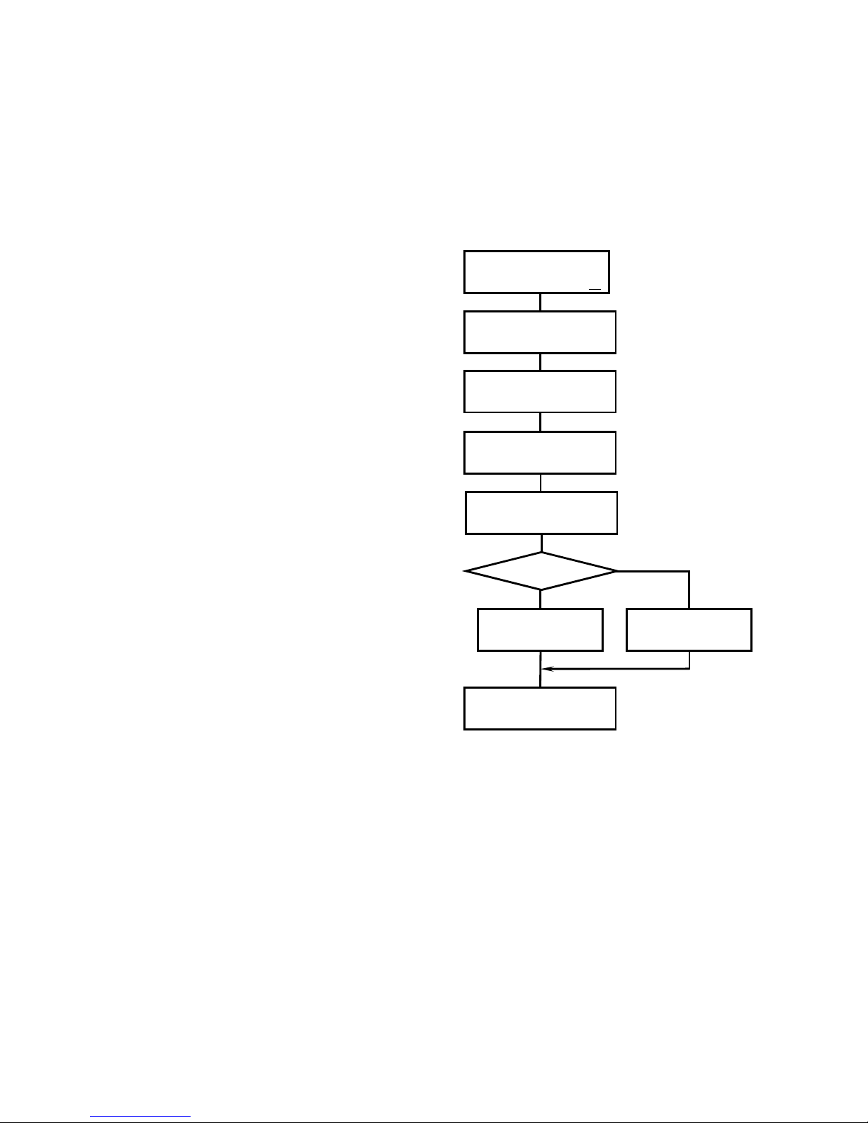
BR256(eSATA+USB3.0)model User Manual
- 78 -
4.3 Deal with 「TWO DRIVE DOWN」
Under RAID 6, for some reasons, there might be possibility that another drive failed after「ONE DRIVE
DOWN」, then 「TWO DRIVE DOWN」will be shown. Same as 「ONE DRIVE DOWN」, the drive might
be temporary failed. Follow the similar process to clarify it.
■How to fix it
① Press MODE button to stop buzzer
② It is recommended to backup your data before
performing recovery. There is possibility that
the system might not work normally during
recovery process even after power recycling.
③ Remove one failed drive and replace with new
drive module.
④ Within 3 minutes, 「RAID-x RECOVERING 0%」
will be shown meaning Recovery process
stared. When 「RAID-x ONE DRIVE DOWN」
is shown, you can start with recovery of 2nd
drive.
⑤ When recovery is succeeded, LCD will display
「 RAID-x NORMAL 」 .If this happened
frequently, please contact your support window
for service. .If it did not return to NORMAL
state, please contact your support window for
service.
RAID-x
TWO DRIVE DOWN ○
Press MODE button to
stop buzzer alarm
Recovery 2nd down
drive
Remove the failed drive
RAID-x
TWO DRIVE DOWN
Replace with new drive
module
Recover Succeed?
RAID-x
ONE DRIVE DOWN
Recommend to
Backup your data first
There might be Alphabet shown
on the message, please take a
memo on it
Page 80
BIOS CORPORATION
- 79 -
4.4 How to deal with 「SYSTEM DOWN」
When「SYSTEM DOWN」occurred, data was assumed to be corrupt and could not be recovered.
Please suspend data write
When「SYSTEM DOWN」 occurred during writing data, the data is not
considered reliably. Please write the date again after system recovery.
■ Steps to check for RAID 0
① Press MODE button to stop buzzer
② It is recommended to backup your data before
performing recovery. There is possibility that
the system might not work normally during
recovery process even after power recycling.
③ Stop the application and Shutdown host
computer
If the system hang up during the normal
shutdown process, please remain
system power-on and contact your
support window. There might be
possibility that data will be corrupted.
④ Shutdown both computer and BR256
⑤ Press and hold the MODE button then turn on
BR256 power
⑥ If LCD showed「RAID-x NORMAL」, it means
BR256 came back to normal. There might be
temporary contact error between HDD and the
backplane. If the system did not come back
to normal, or 「 SYSTEM DOWN 」 is
encountered soon, you should contact your
support window.
※ User can try to replace the suspicious
HDD with a new one. If the situation
remains unchanged, you should
contact your support.
SYSTEM
DOWN ○
Press MODE button to
stop buzzer
Recommend to Backup
your data first
Terminate the app and
shut down computer
Press MODE button and
turn on BR256
RAID-x
NORMAL
SYSTEM
DOWN ○
Yes
No
There might be Alphabet
shown on the message,
please take a memo on it。
Shutdown BR256
RAID-Normal?
Page 81
BR256(eSATA+USB3.0)model User Manual
- 80 -
■ Steps to check for RAID-6
① Press MODE button to stop buzzer
② It is recommended to backup your data
before performing recovery. There is
possibility that the system might not work
normally during recovery process even after
power recycling.
③ Stop the application and Shutdown host
computer
If the system hangs up during the
normal shutdown process,
please remain system power-on
and contact your support
window. There might be
possibility that data will be
corrupted.
④ Please remove two drives with Fault LEDs on
(Not to remove the drive with LED blinking)
⑤ Power off BR256
⑥ Press and hold the MODE button then turn on
BR256 power. Please check if LCD showed
「RAID-x TWO DRIVE DOWN」
⑦ Insert one of removed drive
⑧ Within several seconds、「RAID-1
RECOVERING 0%」should be shown on LCD.
During the recovery, there should be
character 「R」、「X」、「Y」or blank character
shown following the % on LCD, it might mean
the drive connection is problematic. In such
case, turn off the power and do not insert
two failed drives. Start with step 6 again.
⑨ When LCD shows「RAID-x ONE DRIVE DOWN」, you can move to next step following instruction of
section 4.2 continue with recovery from「One Drive Down」State
You should contact support window the status never became 「RAID-x ONE DRIVE DOWN」
※ User can try to replace the suspicious HDD with a new one. If the situation remains unchanged,
you should contact your support.
To recover two failed drives one by one till LCD
shows「RAID-x NORMAL
There might be Alphabet
shown on the message,
please take a memo on it
Yes
No
SYSTEM
DOWN ○
Press MODE button to
stop buzzer
Recommend to backup
your data first
Terminate the
application and shut
Press MODE button and
power on BR256
RAID-x
NORMAL
RAID-x
ONE DRIVE DOWN ○
or
SYSTEM
DOWN ○
Power off BR256
Remove two HDDs with
fault LED lighted
Insert back one of
removed drives above
Recovery Succeed?
Page 82
BIOS CORPORATION
- 81 -
■ Steps to check for RAID-3 / 5
① Press MODE button to stop buzzer
② It is recommended to backup your data
before performing recovery. There is
possibility that the system might not work
normally during recovery process even after
power recycling.
③ Stop the application and Shutdown host
computer
If the system hang up during the normal
shutdown process, please remain
system power-on and contact your
support window. There might be
possibility that data will be corrupted.
④ Please remove the drive with Fault LEDs on
(Not to move the drive with LED blinking)
⑤ Turn off BR256
⑥ Press and hold the MODE button then turn on
BR256 power. Please check if LCD showed
「RAID-x ONE DRIVE DOWN」
⑦ Insert the removed drive back
⑧ Please check if LCD showed「RAID-x
RECOVERING 0%」after seconds. During the
recovery, there should be character 「R」、「X」、
「Y」or blank character shown following the %
on LCD, it might mean the drive connection is
problematic. In such case, turn off the power
and remove the failed drive, starting with
step 6 again.
⑨ If LCD showed「RAID-x NORMAL」, it means BR256 came back to normal. There might be some
temporary disconnections between HDD and Backplane. If the system did not come back to normal, or
「SYSTEM DOWN」is encountered soon, you should contact your support window.
※ User can try to replace the suspicious
HDD with a new one. If the situation
remains unchanged, you should
contact your support.
There might be Alphabet
shown on the message,
please take a memo on it
SYSTEM
DOWN ○
Press MODE button to
stop buzzer
Recommend to backup
your data
Terminate the
application and OS
Press MODE button and
power on BR256
RAID-x
NORMAL
RAID-x
ONE DRIVE DOWN ○
or
SYSTEM
DOWN ○
Yes
No
Power off BR256
Remove the drive with
Fault LED on
Insert the removed drive
back
Recovery Succeed?
Page 83
BR256(eSATA+USB3.0)model User Manual
- 82 -
4.5 LCD Display Under Normal Operation
When all hard disks work normal, LCD will display normal status as below.
SINGLE DRIVE
NORMAL
RAID-1
NORMAL
RAID-0 2 DRIVE
NORMAL
RAID-1 3 DRIVE
NORMAL
RAID-0
NORMAL
RAID-10
NORMAL
RAID-6
NORMAL
RAID-3
NORMAL
RAID-5
NORMAL
4.6 LCD Display for Disk Error
RAID-x
ONE DRIVE DOWN
This means host access is working under one failed drive status.(This won’t be seen on RAID-0 mode)
Please check disk FAIL LED to identify the failed drive. Press MODE button to stop buzzer alarm.
RAID-x
TWO DRIVE DOWN
This means host access is still working under 2 failed drives status.
(This will only be seen in RAID-6 mode)Please check disk FAIL LED to identify the failed drive. Press
MODE button to stop buzzer alarm.
SYSTEM
DOWN
This will be shown if 3 drives failed in RAID-6 mode or 2 drives failed in RAID-3/5 mode, or one drive failed in
RAID-0 mode. The controller will do its best to handle host command, but normal operation is not guaranteed.
Please check disk FAIL LED to identify the failed drive. Press MODE button to stop buzzer alarm.
Page 84

BIOS CORPORATION
- 83 -
4.7 LCD Display for Disk Drive Recovery Status
RAID-x
RCV START WAIT
→
RAID-x
RECOVERING 0%
→
RAID-x
VERIFYING 0%
The drive recovery and verification progress will be shown from 0%, 1% to 99% before completion.
When the process is completed, 「RAID-x NORMAL」will be shown on LCD.
LCD will keep displaying「ONE DOWN」before recovery process has been started.
FAIL LED of associated drive will keep light on till the completion of recovery operation.
4.8 LCD Display for FAN Failure
FAN STOP
NORMAL
When FAN is failed, system FAIL LED will be lighted up and buzzer will be turned on.
Push MODE button to stop the buzzer alarming. If you keep operating BR256 under fan failed situation,
temperature inside the enclosure will be raised and will cause system malfunction or HDD failure. Please
contact support people for the fan replacement right after its failure.
Page 85
BR256(eSATA+USB3.0)model User Manual
- 84 -
4.9 Others LCD Display
4.9.1 Transfer Rate Display
This section explains how to get into display of current data transfer rate. Press MODE and SELECT
button at the same time during operation. Push SELECT button once slowly after Firmware version
shown to read Host transfer rate. Then you can check every Drive access speed by pressing MODE
button. Data transfer rate is checked every 0.5 sec.
HOST
RATE = 0.00MB/S
Channel 0
RATE = 0.00MB/S
Not only useful for checking data transfer rate, this is also useful to check if Activity LED worked normally
or if HDD hang-up is suspected. RATE display will be exited if SCSI reset command was received. Or
you can press MODE and SELECT button at the same time to return to earlier state.
4.9.2 Cache Check Display
When BR256 got into RATE check mode, press MODE button again after checking disk access rate.
The LCD will display Cache memory check by Megabyte.(same as power on cache memory check)
Cache Buffer
Memory xxxM
4.9.3 Most Delay CH Display
Following cache memory check, LCD will display the disk channel with longest delay by pressing one
more MODE button. This access delay is derived from internal retry inside the disk. Disk replacement is
highly recommended if same drive kept having the slowest response.
(This is to show drive with many Retry)
Most Delay
Channel #
Page 86
BIOS CORPORATION
- 85 -
4.9.4 LCD Display for Patrol Mode Options
Following Most Delay CH, Patrol Mode switching can be chosen by pressing MODE button. You can
push SELECT button to switch among 3 different patrol modes
1. NO PATROL Mode
NO
HDD PATROL
No Patrol.
2. AUTO PATROL Mode
AUTO
HDD PATROL xx%
When access from the host is cut off for more than 0.1 seconds, a read will be attempted on every
drive once every amount of time that’s specified in the [SYSTEM PATROL WAIT TIME] option.
The READ will not be executed when access is continuous. If a bad sector is found on a drive, it will
be fixed with the data from another, properly operating drive.
RAID-x
? NORMAL
→
RAID-x
# NORMAL
Bad sector detected Recovery is successful
(The display interval of “?” might be too short to see)
3. FORCE PATROL Mode
FORCE
HDD PATROL xx%
When there is no access from the host, continuous READ operation will be applied to all drives, and if
any error sector was found they will be automatically recovered. Even when the host access is
continuous, a read will be attempted on all drives once every amount of time that’s specified in the
[ SYSTEM PATROL WAIT TIME ] option. When it gets to 100%, depending on the specified
parameters it will either return to [AUTO HDD PATROL] or [NO HDD PATROL].
FORCE PATROL - Effective usage(Incoming test or regular scanning)
It allows you to do self-check on all disks despite of the disk status. It is suggested to do as an
incoming inspection or regularly planning.
※ Even if you chose [ NO HDD PATROL ] when setting your parameters, it is possible to change to
PATROL mode during use. Patrol function will not work during Disk Down (or Recover) states.
The mark that indicates a successful rewrite, (#), disappears when you press the MODE and
SELECT buttons at the same time. Patrol will be restarted from LBA0 when Disk state changed
from Down (or Recover) to Normal.
Page 87
BR256(eSATA+USB3.0)model User Manual
- 86 -
4.9.5 LCD Display for Ethernet Setup
Ethernet setup display will come up following pushing MODE button once after Patrol mode.
By pressing MODE button, Ethernet related setting will be displayed one by one. Parameters can be
changed except MAC Address.
MAC Address
0008:23:00:XX:XX
IP Address
192.168.50.XX
(Changeable)
Address Mask
255.255.255.0
(Changeable)
Gate Way Address
255.255.255.255
(Changeable)
Push MODE button again to return to Transfer RATE display.
4.10 LCD Display for Controller Error
Here explains error shown on LCD display. Buzzer alarm will be sound and can be stopped
by pushing MODE button.
If below error was observed, you should disconnect BR256 from host and contact your
support window.
● Please take a memo on error message
Notice: Error message will be cleared after power down
● Dispatch Error
Dispatch
Nesting Error
Error occurred during Dispatch routine
Page 88
BIOS CORPORATION
- 87 -
● ROM Reading Error
Code ROM Error
System Halted
ROM(Flash EPOM)checksum error
Usually this will only happen at power on.
● Working RAM Error
Work RAM Error
System Halted
Error occurred on working area of RAM
Usually this will only happen at power on.
● Divide by Zero Error
Divide or FPP or
Invalid Code Err
For certain calculation, divide by zero error
● Undefined Interrupt Error
SYSTEM
INTERRUPT Error
Undefined interrupt error
SYSTEM
SBI INT Occur
System break error。
SYSTEM
RIE INT:0x000
This is displayed when a Reserved Instruction Exception has
occurred.
SYSTEM
AE INT:0x000
Address exception error
SYSTEM
TRAP Error
Undefined trap process error
● Cache buffer queue management error
Buffer Manager
Queue Error
Error happens on cache buffer management routine
Page 89
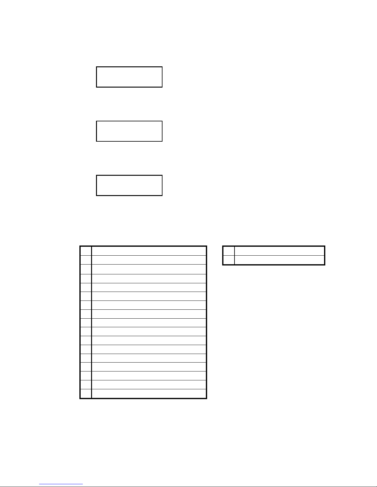
BR256(eSATA+USB3.0)model User Manual
- 88 -
● Cache buffer check error
Cache Buffer
Error 0x#######
Error happens on data access during cache check
● Cache buffer size error
Buffer Size
Error
This is displayed when a data mismatch occurred during a
Cache Buffer Check
● Cache buffer size error
Buffer Manager
Link Error
This is displayed when a data mismatch occurred during a
Cache Buffer Check
■ Extra error indication appended to ONE DOWN/SYSTEM DOWN (drive error)
Hardware Error Software Error
r
IDE register read / write
U
undefined command error
A
disk dma time out ? no pend in exe auto
E
chip busy soft error
B
bad block detected
C
uncorrectable error detected
D
data transfer requested
E
IDE drive busy in start
I
ID not found
M
data address mark not found
O
command aborted
R
IDE drive ready time out
S
unable to find track 0
T
(dummy)busy time out or so
Y
disk not present in write
Z
(dummy)other error
z
other error
L
capacity error
X
disk not present in operation without write
※ There is high possibility of drive error
when you see「S」、「Z」、「z」. Please
remain power on and contact support.
Page 90
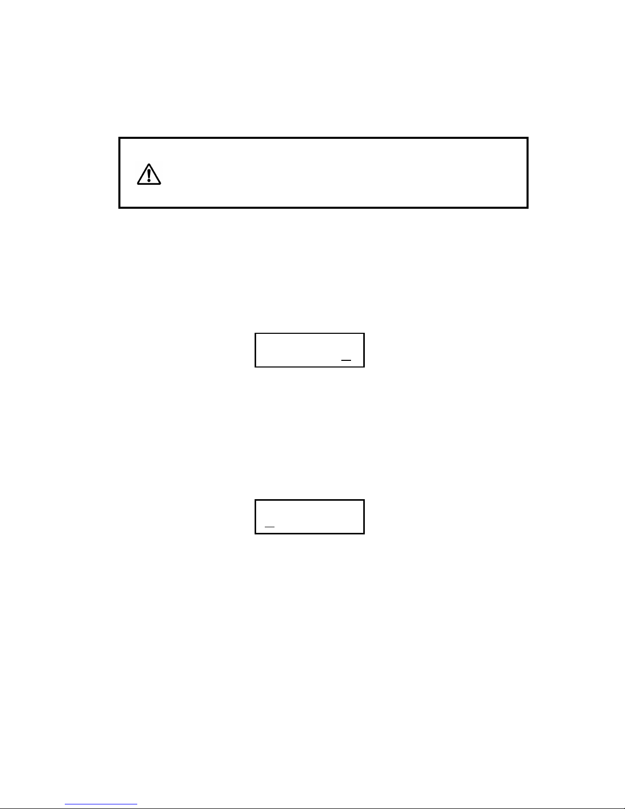
BIOS CORPORATION
- 89 -
4.11 Retry Error Detection/Drive SENSE DATA Display
● Please take a memo on error message
Notice: Error message will be cleared after power down
When a retry occurs, the retry mark will be displayed. When there is a possibility that something on the
host, or drive side could damage the data, the BR256 will cause the drive to stop, but when a Read or
Write error occurs, it will attempt a read and write retry in order to see if it was an accidental error or a
real problem. These retry marks can be cleared by pressing the MODE and SELECT switches
simultaneously while the BR256 is in normal operation to enter Parameter display mode, and then
pushing them both once again.
RAID-6
NORMAL
P
-
A parity error occurred in the host Bus during the completion of the data out
phase
Q - A parity error occurred in the host Bus during the middle of the data out phase
R - A parity error occurred in the host SCSI Bus during the data in phase
I - The initiator detected an error and stopped the operation sequence.
:
-
An error was detected during data out and check conditioning was completed.
.
-
A retry was successful during writing.
RAID-6
NORMAL
:
-
An error was detected during data in and check conditioning was completed.
.
-
A retry was successful during the read process.
!
-
A Rewrite was successful during the read process.
Page 91
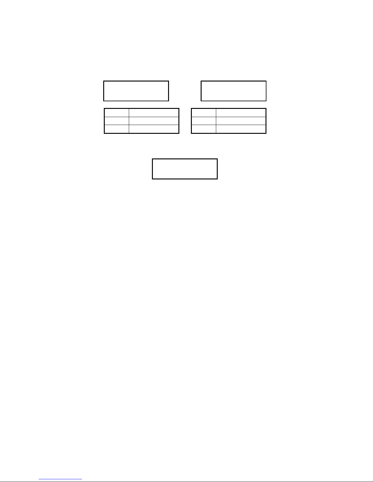
BR256(eSATA+USB3.0)model User Manual
- 90 -
Usage of MODE and SELECT Button
After a retry (drive accesses retry) has occurred in the Read/Write process, you can push the
SELECT switch to see the retry message.
Read Retry in
CH # Err Code = x
Write Retry in
CH # Err Code = x
CH 0
Drive No. 0
CH 3
Drive No. 3
CH 1
Drive No. 1
CH 4
Drive No. 4
CH 2
Drive No. 2
CH 5
Drive No. 5
When a drive is down, an Error Sense Code will be displayed, so please hit the SELECT button.
(Sub-message)
Channel #
Occur error x
[#] is the number of the drive where the retry occurred; [x] indicates the root cause.
[ 4.10 Array Controller Error Messages]
■ONE DOWN/SYSTEM DOWN」 additional error message
When [ONE DRIVE DOWN] or [SYSTEM DOWN] status occurs, you can hit the select button to see the
Sense Data sub-message. If you hit MODE and SELECT switches simultaneously twice, the retry
message will disappear. (But the sub-message will remain.)
If it happens again, you can assume something’s wrong with the drive or the host. You should
contact support for service.
Page 92
BIOS CORPORATION
- 91 -
Data Read Process Data Write Process
Normal Read Flow Normal Write Flow
Display Retry Error
※1:!Mark (Rewrite)
4.12 Other Error
Array controller is considered to have hardware or software fault if any other error
occurred. Record the display content and BR256 status then contact your support window.
Most of time, the system could be recovered after host reset.
Y N Y N N
One Down State
OK?
OK?
Write and Verify※1
Verify
No Retry?
Host Data transfer
Temporary Fail Job
OK?
N
Y
Read
END
Media Error ?
N N N
One Down State
Retry Cnt Down
Write Retry
OK?
No Retry?
OK?
UP?
Retry Cnt Down
OK?
Recover
UP?
Y N Y N Y N N Y Y
END
Write
Data in Cache?
Page 93

BR256(eSATA+USB3.0)model User Manual
- 92 -
‥‥‥‥‥‥‥‥‥‥‥‥‥‥‥‥‥‥‥‥‥‥‥‥‥‥‥‥‥‥‥‥‥‥‥‥‥‥‥‥‥‥‥‥‥‥‥‥
‥‥‥‥‥‥‥‥‥‥‥‥‥‥‥‥‥‥‥‥‥‥‥‥‥‥‥‥‥‥‥‥‥‥‥‥‥‥‥‥‥‥‥‥‥‥‥‥
‥‥‥‥‥‥‥‥‥‥‥‥‥‥‥‥‥‥‥‥‥‥‥‥‥‥‥‥‥‥‥‥‥‥‥‥‥‥‥‥‥‥‥‥‥‥‥‥
‥‥‥‥‥‥‥‥‥‥‥‥‥‥‥‥‥‥‥‥‥‥‥‥‥‥‥‥‥‥‥‥‥‥‥‥‥‥‥‥‥‥‥‥‥‥‥‥
‥‥‥‥‥‥‥‥‥‥‥‥‥‥‥‥‥‥‥‥‥‥‥‥‥‥‥‥‥‥‥‥‥‥‥‥‥‥‥‥‥‥‥‥‥‥‥‥
‥‥‥‥‥‥‥‥‥‥‥‥‥‥‥‥‥‥‥‥‥‥‥‥‥‥‥‥‥‥‥‥‥‥‥‥‥‥‥‥‥‥‥‥‥‥‥‥
‥‥‥‥‥‥‥‥‥‥‥‥‥‥‥‥‥‥‥‥‥‥‥‥‥‥‥‥‥‥‥‥‥‥‥‥‥‥‥‥‥‥‥‥‥‥‥‥
‥‥‥‥‥‥‥‥‥‥‥‥‥‥‥‥‥‥‥‥‥‥‥‥‥‥‥‥‥‥‥‥‥‥‥‥‥‥‥‥‥‥‥‥‥‥‥‥
‥‥‥‥‥‥‥‥‥‥‥‥‥‥‥‥‥‥‥‥‥‥‥‥‥‥‥‥‥‥‥‥‥‥‥‥‥‥‥‥‥‥‥‥‥‥‥‥
‥‥‥‥‥‥‥‥‥‥‥‥‥‥‥‥‥‥‥‥‥‥‥‥‥‥‥‥‥‥‥‥‥‥‥‥‥‥‥‥‥‥‥‥‥‥‥‥
‥‥‥‥‥‥‥‥‥‥‥‥‥‥‥‥‥‥‥‥‥‥‥‥‥‥‥‥‥‥‥‥‥‥‥‥‥‥‥‥‥‥‥‥‥‥‥‥
‥‥‥‥‥‥‥‥‥‥‥‥‥‥‥‥‥‥‥‥‥‥‥‥‥‥‥‥‥‥‥‥‥‥‥‥‥‥‥‥‥‥‥‥‥‥‥‥
‥‥‥‥‥‥‥‥‥‥‥‥‥‥‥‥‥‥‥‥‥‥‥‥‥‥‥‥‥‥‥‥‥‥‥‥‥‥‥‥‥‥‥‥‥‥‥‥
‥‥‥‥‥‥‥‥‥‥‥‥‥‥‥‥‥‥‥‥‥‥‥‥‥‥‥‥‥‥‥‥‥‥‥‥‥‥‥‥‥‥‥‥‥‥‥‥
‥‥‥‥‥‥‥‥‥‥‥‥‥‥‥‥‥‥‥‥‥‥‥‥‥‥‥‥‥‥‥‥‥‥‥‥‥‥‥‥‥‥‥‥‥‥‥‥
‥‥‥‥‥‥‥‥‥‥‥‥‥‥‥‥‥‥‥‥‥‥‥‥‥‥‥‥‥‥‥‥‥‥‥‥‥‥‥‥‥‥‥‥‥‥‥‥
‥‥‥‥‥‥‥‥‥‥‥‥‥‥‥‥‥‥‥‥‥‥‥‥‥‥‥‥‥‥‥‥‥‥‥‥‥‥‥‥‥‥‥‥‥‥‥‥
‥‥‥‥‥‥‥‥‥‥‥‥‥‥‥‥‥‥‥‥‥‥‥‥‥‥‥‥‥‥‥‥‥‥‥‥‥‥‥‥‥‥‥‥‥‥‥‥
‥‥‥‥‥‥‥‥‥‥‥‥‥‥‥‥‥‥‥‥‥‥‥‥‥‥‥‥‥‥‥‥‥‥‥‥‥‥‥‥‥‥‥‥‥‥‥‥
‥‥‥‥‥‥‥‥‥‥‥‥‥‥‥‥‥‥‥‥‥‥‥‥‥‥‥‥‥‥‥‥‥‥‥‥‥‥‥‥‥‥‥‥‥‥‥‥
‥‥‥‥‥‥‥‥‥‥‥‥‥‥‥‥‥‥‥‥‥‥‥‥‥‥‥‥‥‥‥‥‥‥‥‥‥‥‥‥‥‥‥‥‥‥‥‥
‥‥‥‥‥‥‥‥‥‥‥‥‥‥‥‥‥‥‥‥‥‥‥‥‥‥‥‥‥‥‥‥‥‥‥‥‥‥‥‥‥‥‥‥‥‥‥‥
‥‥‥‥‥‥‥‥‥‥‥‥‥‥‥‥‥‥‥‥‥‥‥‥‥‥‥‥‥‥‥‥‥‥‥‥‥‥‥‥‥‥‥‥‥‥‥‥
‥‥‥‥‥‥‥‥‥‥‥‥‥‥‥‥‥‥‥‥‥‥‥‥‥‥‥‥‥‥‥‥‥‥‥‥‥‥‥‥‥‥‥‥‥‥‥‥
‥‥‥‥‥‥‥‥‥‥‥‥‥‥‥‥‥‥‥‥‥‥‥‥‥‥‥‥‥‥‥‥‥‥‥‥‥‥‥‥‥‥‥‥‥‥‥
Page 94
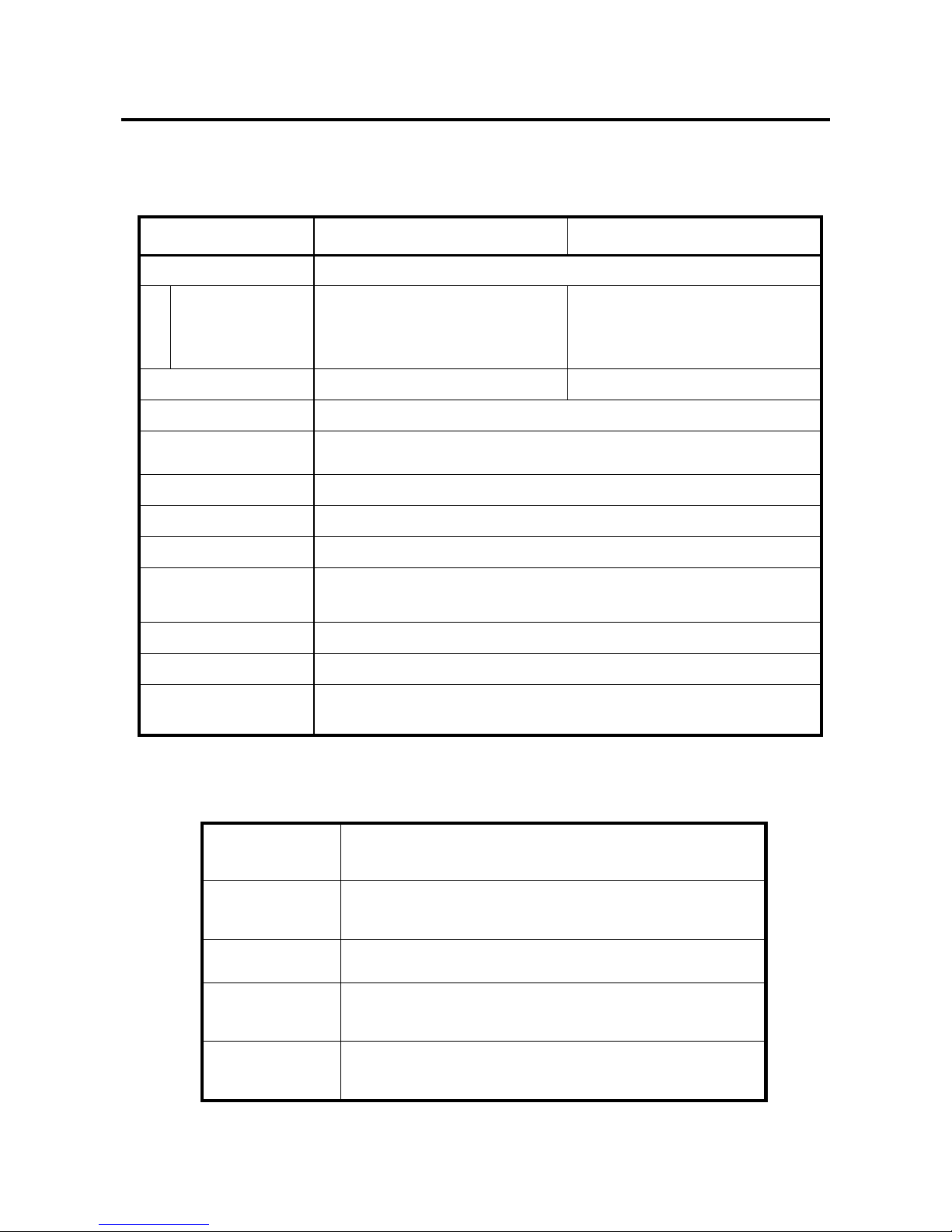
BIOS CORPORATION
- 93 -
Appendix
1. Product Specification
Model
BR256-2506
BR256-5006
RAID Mode
6 / 0 / 3 / 5 / 1 / 0-2 DRIVE / 1-3 DRIVE / 10 / SINGLE DRIVE
Capacity
RAID-0
RAID-6
RAID-3 / 5
1.5TB
1TB
1.25TB
3TB
2TB
2.5TB
Drive
250GB×6
500GB×6
Interface
eSATA, USB3.0, USB2.0
Maximum Speed
eSATA:3Gbps(theoretical), USB 3.0: 5Gbps (theoretical), USB2.0:480Mbps
(theoretical)
Cache Size
128 MB
Logical Unit
LUN:max 8、Support 1 LU more than 2TB
Power Input
AC100~240V±10%、47~63Hz、Full range
Power Consumption
Maximum(startup):43W, Idle:25W, Operation:32W
( ※Vary from hard disk)
Dimension
126 mm(W) × 162 mm(H) × 205 mm(D)
Weight
about 3.5 Kg
Accessory
AC Power cable, eSATA cable, USB3 cable, drive key,
Quick Installation Guide, User Manual(CD-R only)
■ Operating Environment
Ambient
Temperature
Operating : 5 ~ 35 ℃
Storage :- 40 ~ 60 ℃
Humidity
Operation : 20 ~ 80 %
Storage : 5 ~ 95 %
Dust
General office environment
Shock
Operating : 5 G
Storage : 50 G
Altitude
Operating : 0 ~ 3000 m
Storage : 0 ~ 12000 m
Page 95
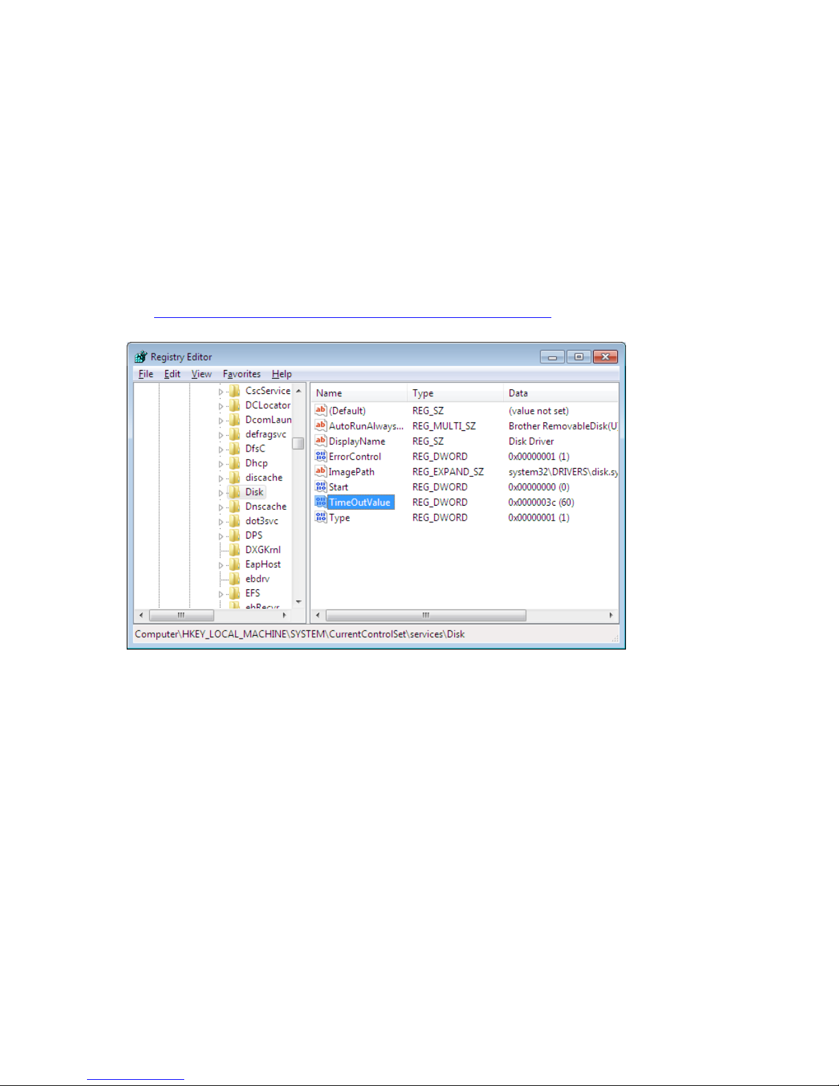
BR256(eSATA+USB3.0)model User Manual
- 94 -
2. Disk Time Out Value Setup
From Windows Menu go to [Start] -> [Run] and enter [regedit] to start register editor:
Go to:
HKEY_LOCAL_MACHINE\SYSTEM\CurrentControlSet\Services\Disk\
In general, 60 second(hex:3c) is the most popular setting
*If there is no TimeOutValue registry at the above location then create new one as DWORD then put
name as [TimeOutValue] then value as [3c] in hex format
Please refer to following link for further information:
http://technet.microsoft.com/en-us/library/aa997069(EXCHG.80).aspx
Page 96
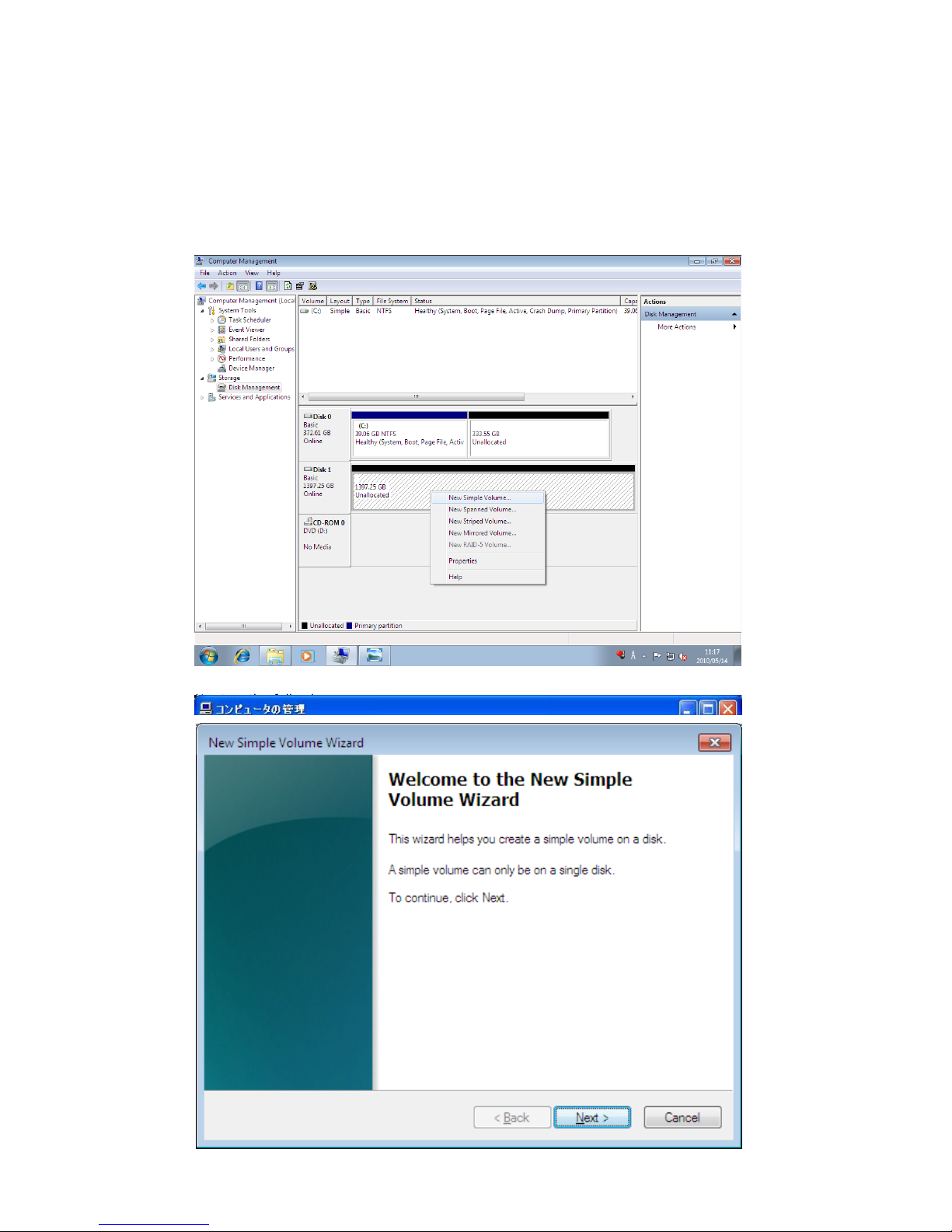
BIOS CORPORATION
- 95 -
3. How to change Cluster size(Allocation Unit Size)
during Format under Windows OS
①Right click on My Computer and select Manage
②Select Disk Management from Storage sub-menu. Find the target DISK and right click to
choose New Partition
③Click Next on the following screen
Page 97
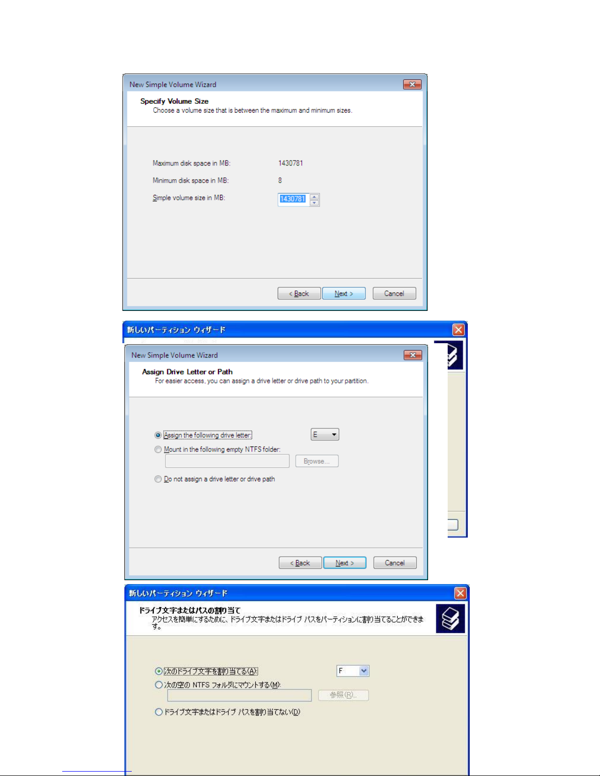
BR256(eSATA+USB3.0)model User Manual
- 96 -
④Input size of the partition and click on Next
⑤Choose Drive Letter and click on Next
Page 98
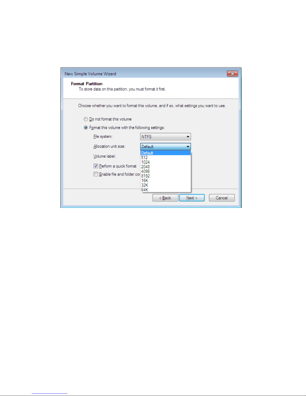
BIOS CORPORATION
- 97 -
⑥Select to Partition with below setting and choose to change allocation size from the pull down
manual(Here 2048 for example))
Page 99
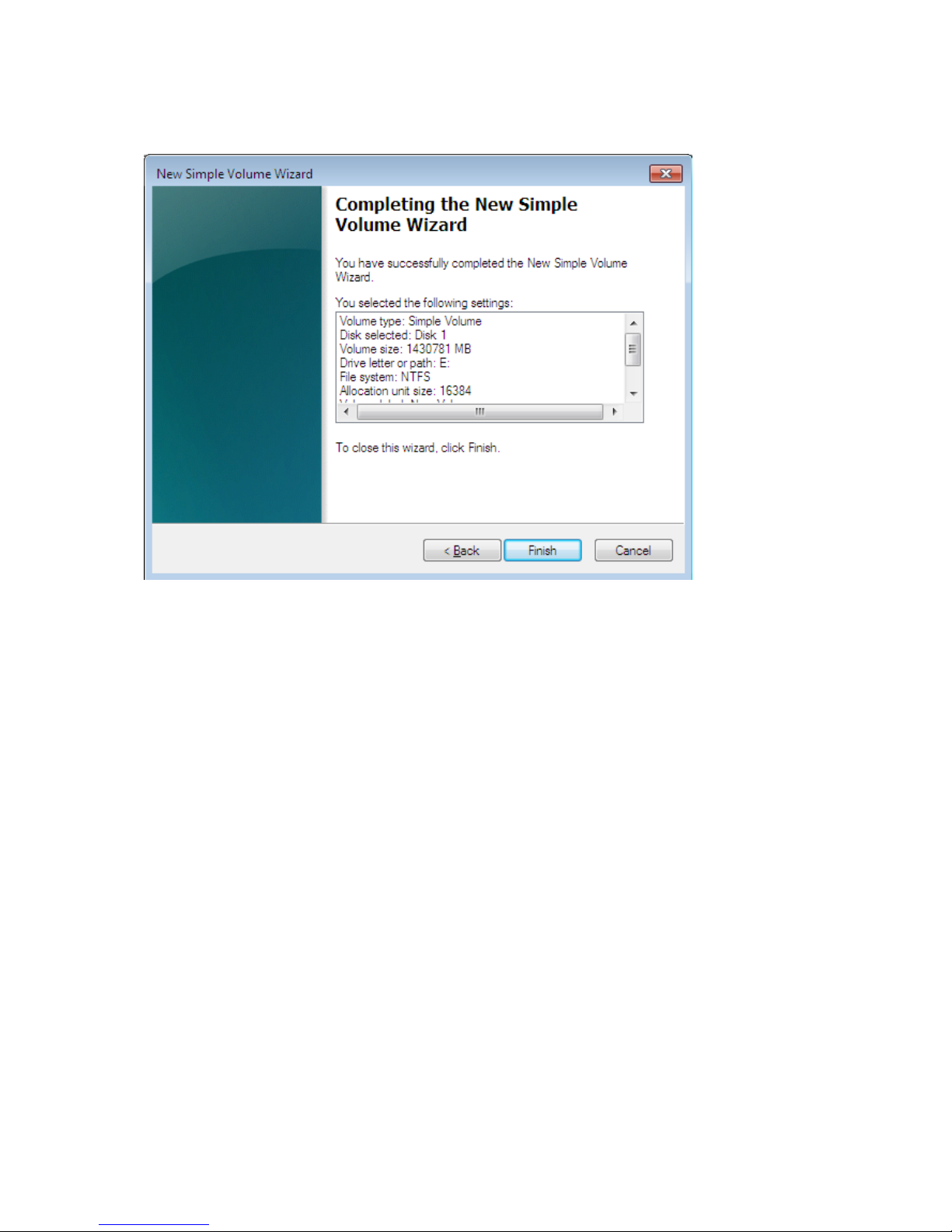
BR256(eSATA+USB3.0)model User Manual
- 98 -
⑧Optionally choose Quick Format and compression
⑨Click on Finish to confirm the completion
Page 100
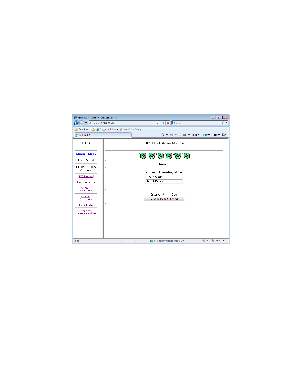
BR256(eSATA+USB2.0)model取扱説明書
- 99 -
4. To use SNMP MIB for Status Monitor
1.Overview
This section will only explain SNMP usage for disk array device.
2. Setup Parameter (SNMP)
Based on pre-defined status criteria, the disk array device can be monitored via network.
① Launch the web browser with IP of BR256
 Loading...