

Page 1
Model P720 Peristaltic Pump
Operation Manual
NOTE: This pump is a laboratory device. It is not
Instech Laboratories, Inc. cannot assume liability from i m proper use of its products.
not intended for use on humans.
notnot
Page 2

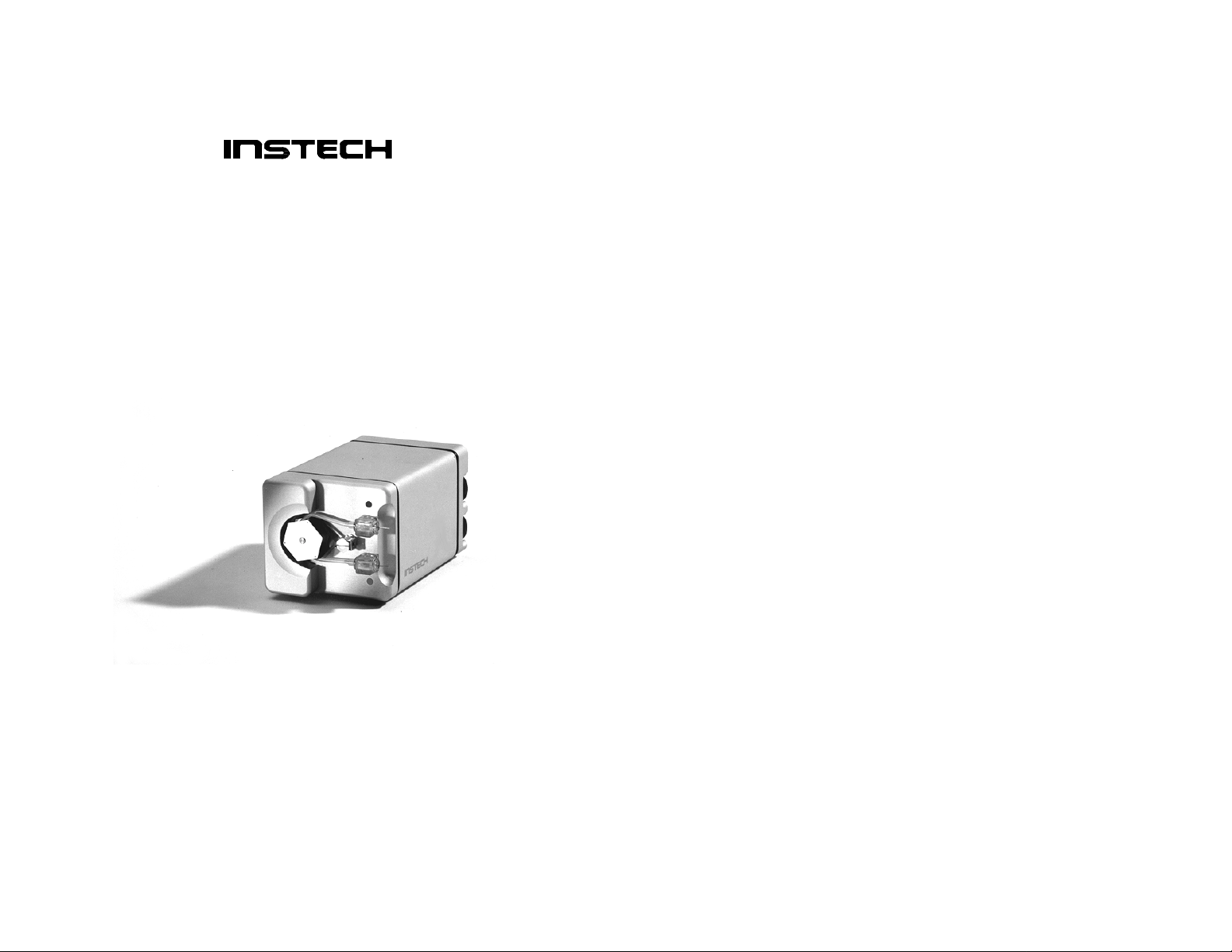
Instech’s Model P720 pump is a full-featured, miniature peristaltic
pump designed specifically for low flow laboratory applications.
Instech’s wide variety of pump tube sets let you configure this
pump to run at flow rates from 0.2 to 180 ml/hr, to work with a
variety of solutions, and to pump in single or dual channel mode.
The Model P720 can operate as a stand-alone pump or as an element in closed loop control applications using the external speed
control input. The pump has an internal battery that will operate
the pump continuously for up to 30 hours if the power should fail
or if you just want to move the pump around your lab without
turning it off.
This pump’s circuitry has been designed to minimize electromagnetic radiation, making it ideal for use near sensitive microelectrodes. For quietest operation, run the pump using the internal
battery.
1
Page 3
p
)
p
co n
Set-up
Check for signs of shipping damage. You should have received:
1 ....Model P720 pump
1 ....Wall mounted 9V DC power adapter
2 ....Pump tube sets (of your choice)
1. ...9V lithium battery
1 ....3.5mm stereo jack (for external speed control)
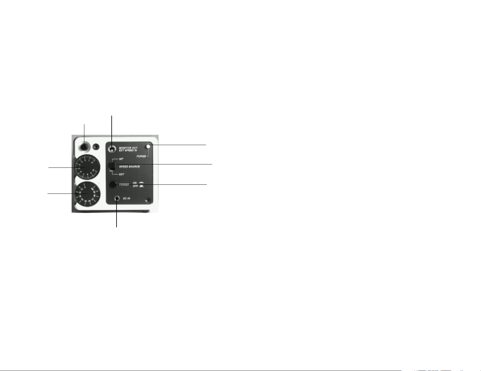
Monitor output and external analog control input –
Motor run/stop
use stereo jack for co n nection
Pump runs at full speed
while pressed
Fine
eed
s
Coarse speed
trol
Input for 9VDC power adapter
(does not charge battery)
Model P720 pump controls
Speed source selector
(set to INT for normal use)
Power on/off (Red LED
on pump head indicates
ower on
Battery Installation
1. Place POWER switch in off position (out).
2. Remove screw holding access cover on underside of pump and
remove plate.
3. Withdraw connector and attach to battery terminals. A lith-
ium U9VL is preferred due to its long shelf life and higher capacity (about twice the operating time as an alkaline)
although an alkaline will suffice.
4. Make sure that the removal ribbon is below the battery.
2
Page 4

5. Place the battery into the compartment and replace access
plate.
Testing Battery Backup Operation
1. Place speed source selector in INTernal position.
2. With no external adapter attached, turn on POWER switch
and check pump end for illumination of red LED.
3. Press PURGE. The rotor should turn at full speed.
4. Set speed to some value other than zero and turn on motor by
pressing the RUN/STOP button.
5. While motor is running, check that the amber LOW BAT-
TERY LED has not come on (battery voltage below 7.5V); if
so, replace battery.
Pump Tube Installation
1. Slip the tubular portions extending from the bottom of the
connector blocks into the mounting holes with the silicone
tube just above the rotor.
2. Actuate the rotor, using the PURGE button, while guiding the
tubing down and around the rotor with your finger (see figure
below).
3. Press in both connectors so that they align with the square
depressions in the pump.
4. Again press PURGE button to check that the tube has been
correctly installed and that the amber Kapton tape has not
been displaced. There will be slack in the tape as the rotor
turns; this is normal.
3
Page 5
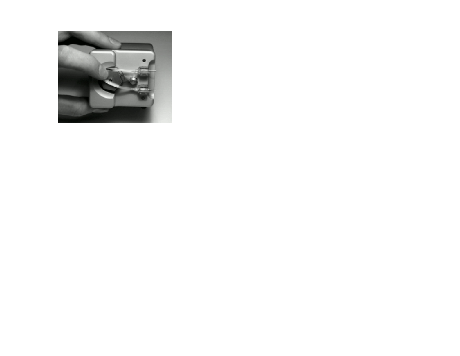
Pump tube installation
Pump Tube Removal
1. Press the purge button.
2. Lift the input side of the tube out of the holder.
3. As the rotor turns, lift the input side until the entire tube has
disengaged.
4. Remove the output side from its holder.
4
Page 6

Operation
Stand Alone Operation
1. Insert the power jack into the pump first, then plug the 9V DC
wall mount supply into an AC outlet.
2. Press in the pump POWER switch.
3. Attach inlet and outlet lines as required. Due to the low flow
rates, it is usually best to attach the lines to the pump tube
connector, fill the system, clear any air bubbles, pinch off the
line to stop any flow and then install the pump tube into the
pump as described above. The rotor will prevent flow when it
is not turning. Pump tube installation may be performed
without the external supply if it is more convenient.
4. Set desired flow rate using the two setting control knobs in
conjunction with previously obtained calibration plot of flow
vs. Dial Settings or MONITOR Voltage (see Calibration).
5. Check that SPEED SOURCE is in the INTernal position. If
this switch has inadvertently been moved to the EXTernal
position without an external input the pump will not run or
respond to dial settings.
6. Press MOTOR RUN/STOP button to start pumping. Use this
button to start and stop the pump rather than the POWER; it
provides more rapid starts and stops.
External Speed Control
In this mode you will be supplying an analog voltage to control
the speed of the pump. Bi-directional control is possible using this
mode. The MOTOR RUN/STOP behaves normally. Set the
SPEED SOURCE to EXTernal and apply the voltage via the center
ring of the 3.5 mm stereo phono jack input at the top of the
control panel.
5
Page 7

EXT speed input
GND
Set voltage monitor
Stereo jack connections for EXTernal speed control
The control voltage passes through the speed control potentiometers and can be attenuated via the knob settings. This is a useful
feature when operating more than one pump from a common
control line since it allows individual speed adjustment for each
pump. It is also useful when a digital level is used as a control
voltage.
The input parameters are as follows:
Ensure that maximum MONITOR VOLTAGE (after knob at-
tenuation) does not exceed ±1.75 volts. An input of +1.5V will
produce a MONITOR voltage of about –1.75V when the dials are
at 100 and 10.
Zero volts = Zero flow rate (actively controlled). Note: TTL 0
state may not be 0 volts. CMOS is usually close enough to work
directly.
Positive Control voltage will cause the rotor to rotate clockwise
(outflow will be on the top).
Negative control voltage will cause the rotor to rotate counterclockwise (outflow on the bottom).
To establish the maximum dial setting (assuming you desire full
motor speed at your full peed signal):
1. Set Speed Source to EXT.
2. Apply power and press Power Switch IN.
3. Turn dials to 0.
4. Apply the maximum control signal that your system will de-
liver. Increase the dials until the MONITOR voltage reaches a
maximum of 1.75V.
5. You may now perform a calibration of Flow vs. Monitor
voltage as detailed below by either varying the incoming sig-
6
Page 8

0 20 40 60 80
0 10 20 30 40 50 60 70 80 90
nal or with a constant input and varying the dials. Remember
not to exceed the values determined in step 4 above.
6. Turn on the MOTOR RUN/STOP switch. You may leave the
switch in this position and stop the pump by applying zero
volts to the control input.
Calibration
Instech’s peristaltic pumps use tube sets of different sizes to cover
the range of flow rates from 0.2 to 180 ml/hr (see chart below).
To determine the flow rate at a given rotor speed you will need to
calibrate your pump. We have designed our pumps so that the
relationship between the rate setting on the controller and the
rotor’s speed is extremely linear; therefore, in most cases you only
need to perform a single-point calibration. For maximum accuracy, we recommend that you calibrate each pump tube that you
use, since each tube set may vary slightly.
180
160
140
120
100
Dial Setting (INTernal speed control)
Dial Setting (INTernal speed control)
Dial Setting (INTernal speed control)Dial Setting (INTernal speed control)
.093" ID
.062" ID
.031" ID
.020" ID
.015" ID
100 110
1. Attach either the inflow or the outflow tube to a container on
a balance, or one whose weight is precisely known. Ensure
that all the air has been removed from the lines.
7
Page 9

2. Set the pump dials to 110 to run the motor at maximum speed
(coarse speed control: 100, fine speed control: 10), and turn
on the pump motor. (Alternatively, when using the external
speed control, or when you need more precision, you may
calibrate vs. Monitor Voltage instead of dial settings. To read
the Monitor Voltage connect a digital voltmeter between
ground and the tip of the 3mm stereo jack plugged into the
monitor jack.)
3. Collect or withdraw a timed sample, typically for 10 minutes.
The total delivered volume upon which the calibration is
based should exceed 0.5 ml (approximately 6 minutes when
using the smallest tubing), assuming that the sample is being
weighed with a resolution of 1 mg.
4. Weigh the sample and calculate the actual flow rate. Flow
rates should be linear with dial settings between 3 and 110.
Reservoir
Scale
Tips for Most Accurate Calibration
• Calibrating the pump by measuring the sample in a graduated
pipette is usually less accurate than weighing the sample as
described above.
• When using new tube sets, run the pump at full speed for 20
to 30 minutes to allow the pump tube to stretch into its final
shape.
• Use the same liquid that you will be using under actual oper-
ating conditions.
8
Page 10

• When calibrating at very low flow rates, beware of evapora-
tion. Use a covered container or one with a small surface
area.
• If possible, simulate the pressure differences across the pump
tube that will be experienced under actual operating conditions. Increased back pressure on the outflow side will cause a
slight increase in delivery rate due to tubing dilation, though
this effect is usually less than 1%.
Replacement Parts
Kapton Strips
This amber strip reduces tube wear and minimizes the tendency
for the peristaltic action to walk the tube through the pump,
which can stretch the tube and alter the flow rate calibration. The
strip should never be tight around the rotor. Replacement strips
area available—specify part number KSK.
Tube Sets
Your Model P720 pump includes 2 pump tube sets that were chosen when you ordered the pump. Tube sets will typically last
about one month under continuous operation. Dual tube sets
place greater stress on the pump motor than do single tube sets,
and thus they may shorten the life of the motor.
You may order additional tube sets directly from Instech. First
choose the size of tube you need based on your expected flow rates
(refer to the graph above). Next choose the tube material and
inlet and outlet connectors using the table below. When ordering,
give us a part number that specifies: inlet connector–tubing–outlet
connector. For example, LL-020S-22 specifies a single channel
.020” silicone tube with a male Luer lock inlet connector and a 22
gauge hypodermic tubing outlet connector. Note that you can
have different inlet and outlet connectors on the same tube set.
Call for current prices.
9
Page 11
-
-
- - -
- - -
- - -
- - -
- -
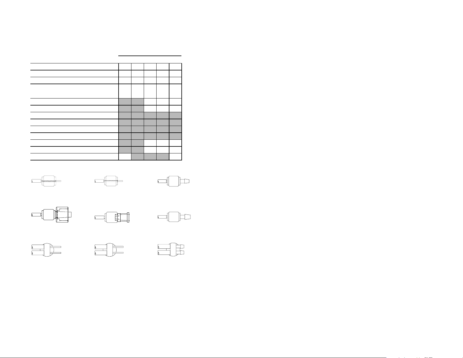
Available tube set materials, sizes and connectors
Tube size (ID)
Material Infusate
Silicone Saline, most drugs
C-FLEX® IV diets with fats
VITON® Petroleum-based fluids
.015" .020" .031" .062" .093"
015S
015S 020S
020S 031S
031S 062S
062S 093S
015S015S
020S020S
020C
020C 031C
020C020C
020V
020V - 062V
020V020V
031S031S
031C 062C
031C031C
093S
062S062S
093S093S
062C 093C
093C
062C062C
093C093C
062V -
062V062V
Channels Inlet and outlet conne c tors
Single 22 gauge tubing
Single 20 gauge tubing
Single .062" ID barb (soft plastic) BS
Single Male Luer lock
Single Female Luer lock
Single .093" ID barb (soft plastic) 93
Dual
Dual
Dual
VITON is a registered trademark of DuPont Dow Elastomers LLC. C-FLEX is a registered trademark of Consolidated Polymer Technolgies, Inc. Tygon is a registered trademark of Norton
Performance Plastics Corporation.
22
22 22 gauge tubing
2222
Fits PE50, .020” Tygon®
LL
LL Male Luer lock
LLLL
Fits female Luer, .093” Tygon®
D22
D22 Dual 22 gauge tubing
D22D22
Fits PE50, .020” Tygon®
22 gauge tubing
20 gauge tubing
.062" ID barb (soft plastic) DBS
D22
D22
D22D22
D20
D20
D20D20
DBS
DBSDBS
20
20 20 gauge tubing
2020
Fits PE100, .030” Tygon®
FL
FL Female Luer lock
FLFL
Fits male Luer lock
D20
D20 Dual 20 gauge tubing
D20D20
Fits PE100, .030” Tygon®
.015" .020" .031" .062" .093"
22
22
2222
20
20
2020
BS
BSBS
LL
LL
LLLL
FL
FL
FLFL
93
9393
BS
BS .062” ID barb
BSBS
Fits .062” Tygon®
93
93 .093” ID barb
9393
Fits .093” Tygon®
DBS
DBS Dual .062” ID barb
DBSDBS
Fits .062” Tygon®
Tube Set Connectors
10
Page 12

1 lb
Accessories
Instech also offers a range of accessories and replacement parts for
its peristaltic pumps. Call for current prices.
Part Number
RMC
KSK
720BATT
9 VDC/120
9 VDC/220
Description
Rod mounting clamp. Attaches P720 and P820 pumps and controllers to
standard rod mounting systems (including Instech’s UNIMOUNT).
Kapton strip replacement kit. 20 protective strips, 5 retaining clips and 1
insta l lation tool.
9V lithium battery for P720 pump.
120 VAC power adapter for P720 pump.
220 VAC power adapter for P720 pump.
Specifications
Rotor type
Rotor speed
Power supply voltage
RPM supply sensitivity
Typical operating current – single tube
Typical operating current – dual tube
Typical idle current
Monitor voltage (INT)
Nominal external voltage (EXT)
Recommended battery
Alternative battery
Battery voltage triggering amber Lo Bat LED
Size ( WxHxD)
Weight
Typical repeatability
Linearity vs. dial setting
Accuracy
Maximum pressure – .015”-.020” ID tube
Maximum pressure – .031”-.093” ID tube
Printed December 1997
720manln.doc
3 roller
.4 – 14 RPM
+8 to 12 V DC
–.08 %/Volt
25 mA
30 mA
14 mA
±
0 to
1.46 VDC
±
±
1.5 to
10 VDC
Lithium U9VL
Standard 9V alkaline
~7.5 V
2.5”x2.25”x4”
±
3%
±
3%
±
5%
20 PSI
5 PSI
11
Page 13

Instech Laboratories, Inc.
Instech has been a leading provider of
instruments for medical and biological
research for over 25 years. Our reputation
for quality and reliability is recognized by
research facilities, universities and a wide
range of companies throughout the world.
Our design and manufacturing
capabil i ties include:
• Small fluid pumps
• Continuous animal infusion systems
• Dissolved oxygen measurement systems
• Cuvette stirring systems
• Motor controllers
• New product design and development
For more information on the complete line
of Instech systems and custom products, call
us at 800-443-4227 or visit our website at
www.instechlabs.com.
The equipment behind the science.
Instech Laboratories, Inc.
5209 Militia Hill Road
Plymouth Meeting, PA 19462-1216
800-443-4227 • 610-941-0132
FAX 610-941-0134
EMAIL support@instechlabs.com
WEB www.instechlabs.com
 Loading...