

Page 1
FCS3 Micro-Environmental Chamber Instructions
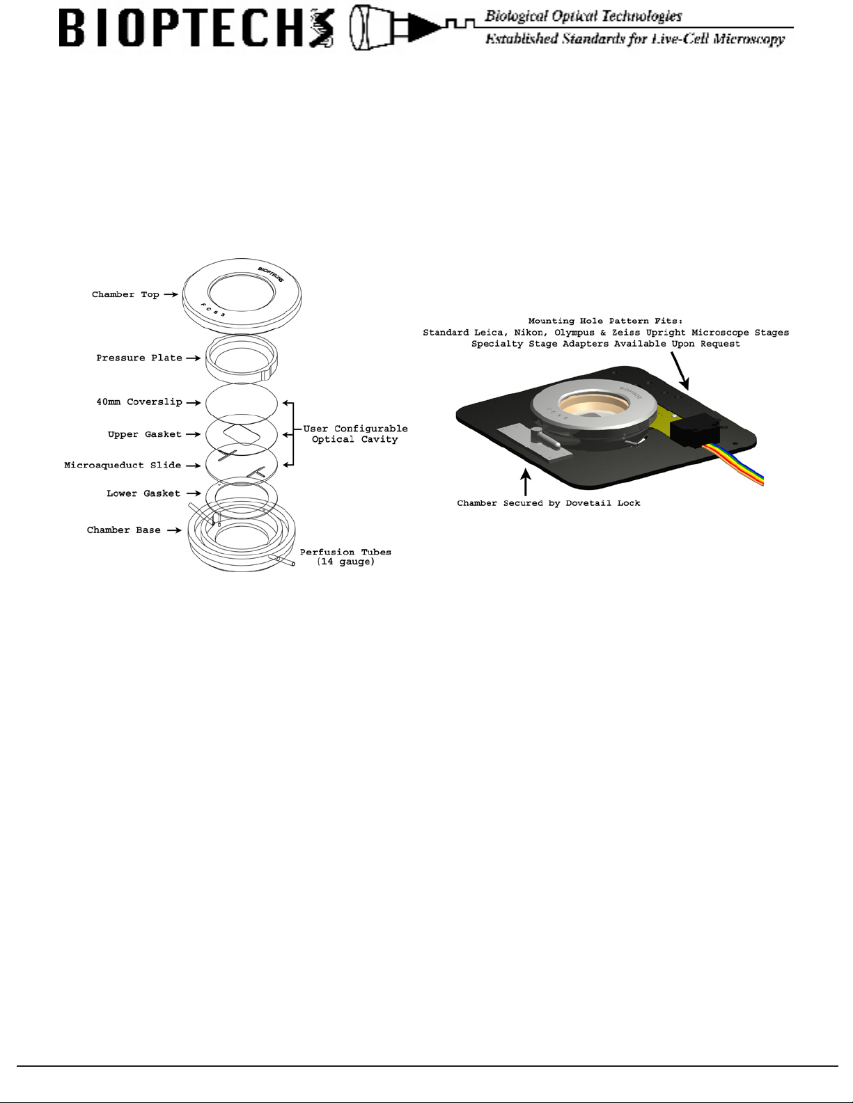
Chamber
The chamber is shipped without glass components installed.
To open the chamber, turn the knurled lid counterclockwise with respect to the dovetailed base. Remove the keyed
pressure plate made of PEEK™.
The following components of the chamber can be autoclaved: dovetailed chamber base, all gaskets, coverslips, and the
knurled top.
Loading the Chamber
1. Attach inow and outow perfusion lines to the 14ga needles.
2. Hold the dovetailed chamber base in the upright orientation as shown and place the lower gasket (.75mm
thick) into the recess while aligning the perfusion clearance holes with the perfusion tubes.
3. Place a microaqueduct slide, groove side up, onto the gasket and oriented such that the perfusion tubes
align with the holes in the microaqueduct slide.
4. Select an upper gasket of the appropriate thickness and internal geometry for your experiment on the
microaqeduct slide and press in place.
5. Place the 40mm coverslip (cell side down) on top of the gasket.
6. Place the PEEK pressure plate on top of the coverslip (wide edge down) oriented in a manner to engage
the two recesses on the perimeter of the base.
7. Screw the knurled chamber top onto the dovetailed chamber base thus compressing the gaskets to the
optical components.
8. Plug in the 4-pin connector to the back of the chamber; orientation does not matter (non-polarized).
9. Rotate the locking lever fully counter clockwise then place the chamber into the stage adapter with the
4-pin plug facing away from you and the dovetail engaging the adapter plate.
10. Turn the locking lever clockwise to engage and secure the chamber to the stage adapter plate.
11. Plug the rainbow colored wire into the controller (6 Pin mini DIN) and follow the controller instructions.
3560 Beck Road • Butler, PA 16002 • Voice: 724-282-7145 • Fax: 724-282-0745 • E-mail: info@bioptechs.com • Web: www.bioptechs.com
Page 2
3560 Beck Road • Butler, PA 16002 • Voice: 724-282-7145 • Fax: 724-282-0745 • E-mail: info@bioptechs.com • Web: www.bioptechs.com
Before You Begin:
• Check to make sure there is no visible damage in shipment and save all packing materials.
• The Controller box should contain; controller, power cord, 2.5mm screwdriver, 1/8” jack, and 3 pin mini
DIN connector.
• Check the packing list and call your supplier if there are any discrepancies.
The FCS3 is comprised of three main parts. An electronic controller, the chamber (optical cell cavity) and
the stage adapter that supports the chamber on the microscope.
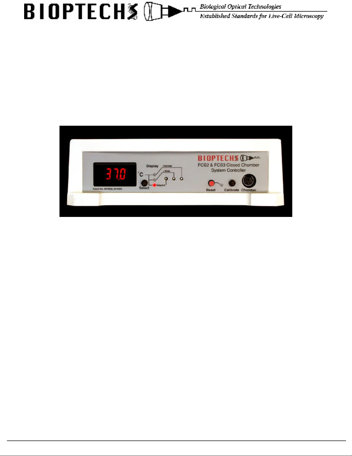
Controller:
Front Panel of FCS2 & FCS3 Controller
Numeric Display should be illuminated when the controller is turned on. If it does not light, check the main
power source, then the fuse block located in the power input module where the AC power cord plugs in.
Display Selector is the black button adjacent to the display. It selects the source of the information displayed.
When the controller is turned on, the default condition is to display the setpoint value indicated by the red light
adjacent to the word Setpoint. The button selects one of a sequence of display options. This button can be
pressed at any time and has no effect on the temperature regulation functions of the controller.
Display Lights indicate the source of the value displayed on the numeric display.
Setpoint is adjusted by a potentiometer accessible with the 2.5mm screwdriver provided. To adjust the setpoint
set the numeric display to Setpoint, then adjust the potentiometer to the desired value. If you need to change
the setpoint value during your experiment on a routine basis there is a remote setpoint jack on the back of the
controller. See Remote Setpoint.
Slide is the location where the calibration of the circuit reading the Microaqueduct Slide can be adjusted.
Chamber is the location where the calibration of the circuit reading the Chamber can be adjusted.
Reset (Red Button) resets the controller if the alarm sounds. Note: If the alarm went off there must have been a
reason. Check the chamber before resetting the controller.
Calibrate substitutes precision resistors into the circuit that reads the thermistors so that calibration adjustments
can be made to a known value.
3560 Beck Road • Butler, PA 16002 • Voice: 724-282-7145 • Fax: 724-282-0745 • E-mail: info@bioptechs.com • Web: www.bioptechs.com
Page 3
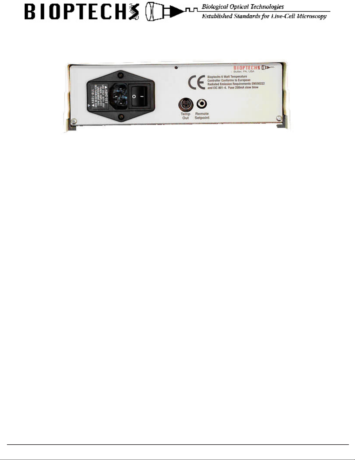
Chamber is a six pin mini DIN socket where the FCS3 is connected.
Back Panel of the FCS2 & FCS3 Controller
AC Power line input, power switch, voltage selector, and fuses are all incorporated in the AC Power Input
Module. The controller can operate between 90 - 260V 50-60Hz, or a 24V battery can be used as an alternate
power supply. The fuse carrier contains two 0.5A slow blow fuses. The fuses can be accessed by prying the
fuse block out of its socket with a small screwdriver wedged under the small slot in the opening of the AC line
receptacle. When replacing the fuse block, make sure to align the arrow on the outside of the fuse block with the
closest voltage value to your supply line voltage:
For 90-130 supply line voltage place the fuse block with the arrow pointing to 110-120V.
For 180-260 supply line voltage place the fuse block with the arrow pointing to 220-240V.
Temp Out is a voltage output direct from two instrument ampliers reading the thermistors from channel A and
B. The voltage output from this socket is temperature / 10. 37.0°C = 3.70 Volt DC.
The left pin (as you look at the back of the controller) is channel A, center pin is channel B, and right pin is
ground.
Remote Setpoint is an analog input that allows the user to set the controllers setpoint from an external DC
source. The sleeve is earth ground. A DC voltage can be applied to the tip of this jack equal to temperature
/10. i.e.: 28.5°C = 2.85 Volt. When the jack is inserted into the controller it will automatically switch to the
jacks value. When removed it will default to the setting on the front of the controller. Use for programming or
cycling operating temperatures.
3560 Beck Road • Butler, PA 16002 • Voice: 724-282-7145 • Fax: 724-282-0745 • E-mail: info@bioptechs.com • Web: www.bioptechs.com
Page 4

3560 Beck Road • Butler, PA 16002 • Voice: 724-282-7145 • Fax: 724-282-0745 • E-mail: info@bioptechs.com • Web: www.bioptechs.com
Controller Operation:
1. Turn the unit on using the main on-off switch located on the rear panel. The Chamber need not be
plugged in at this time. All further adjustments are made on the front panel.
2. Set the display switch to the “SET” position. Insert the enclosed screwdriver into the hole marked
Setpoint and adjust the controller to the desired setpoint.
3. Set the display to the “Slide” or “Chamber” position. The LCD will display a number between -1.8 and
-4.2. This is normal.
4. Press the black button labeled “CALIBRATE” and make sure the display reads 26.6°C when “Slide”
is selected and 25.0 when “Chamber” is selected. If adjustment is necessary, turn the corresponding
screws in the adjustment holes with the enclosed screwdriver. CW = increase, CCW = decrease.
5. Turn the controller off.
6. With the chamber loaded, plug the chamber into the controller.
When the controller is turned on and the display switch is set to “Slide” or “Chamber” it will read the ambient
temperature, and then slowly begin to rise until it reaches setpoint temperature. We recommend leaving the
display switch in the “Slide” position because it is the closest representation of the cell temperature.
Special Notes:
There is a safety cut-off circuit that protects the cells if the microaqueduct drops below 0.9°C from the setpoint
after reaching setpoint minus 0.9°C. Only during a cold start will the safety cut-off circuit ignore the out-ofrange condition. This safety circuit will shut off power to the slide circuit only and sound the alarm. If the
alarm sounds, the user should correct the problem and press the red reset button located next to the red LED.
The alarm may sound as a result of the following conditions:
• Perfusion rate exceeds the rate which temperature stability can be maintained. To correct, press the red
reset button as soon as the alarm sounds. This will reset the logic back to cold start up mode. Setpoint
temperature will return within 15-20 seconds.
• An interruption in AC line power may cause the logic levels to change state.
• Physical displacement of the thermistor from the microaqueduct surface.
Additional information:
• The thermistor that regulates the chamber frame is sealed internally eliminating accidental displacement.
Therefore, there is no need for an alarm on the chamber frame circuit.
• The display can be switched between Set, Slide and Chamber at any time to monitor temperature
without interfering with the regulation. If the Chamber was preheated it will come up to temperature in
about 1 minute. Otherwise it will take longer.
• Note: The vertical portion of the drain tubing, which extends down from the stage to your waste
receptacle will create a siphon and form negative pressure in the chamber. This negative pressure will
cause the coverslip to ex. This can be eliminated by breaking the siphon at a point equal to the height
of the specimen with a “T” tting.
Continual Perfusion with the Micro-Perfusion Pump:
Bioptechs recommends the FCS3 Micro-Perfusion Pump due to its smooth ow prole in slow, ow
applications. If dual ow is needed there is also a PC interface board and program that enables alternate control
of two pumps to regulate the acceleration and run time of each. The Micro-Perfusion Pump Controller (PC
interface) is ideal for changing concentrations of media.
3560 Beck Road • Butler, PA 16002 • Voice: 724-282-7145 • Fax: 724-282-0745 • E-mail: info@bioptechs.com • Web: www.bioptechs.com
 Loading...