

Page 1
FCS2 (Focht Live-Cell Chamber System) Instructions
A Message from the Developer:
The FCS2 utilizes the most advanced technology for optimum functionality and versatility for the observation of living cells on a
light microscope. As part of our dedication to respond to our customers needs we would be very appreciative of any comments or
suggestions you may have relative to our products continued improvement.
Before You Begin:
• Check to make sure there is no visible damage in shipment and save all packing materials.
• The Controller box should contain; controller, power cord, 2.5mm screwdriver, 1/8” jack, and 3 pin mini DIN
connector.
• Check the packing list and call your supplier if there are any discrepancies.
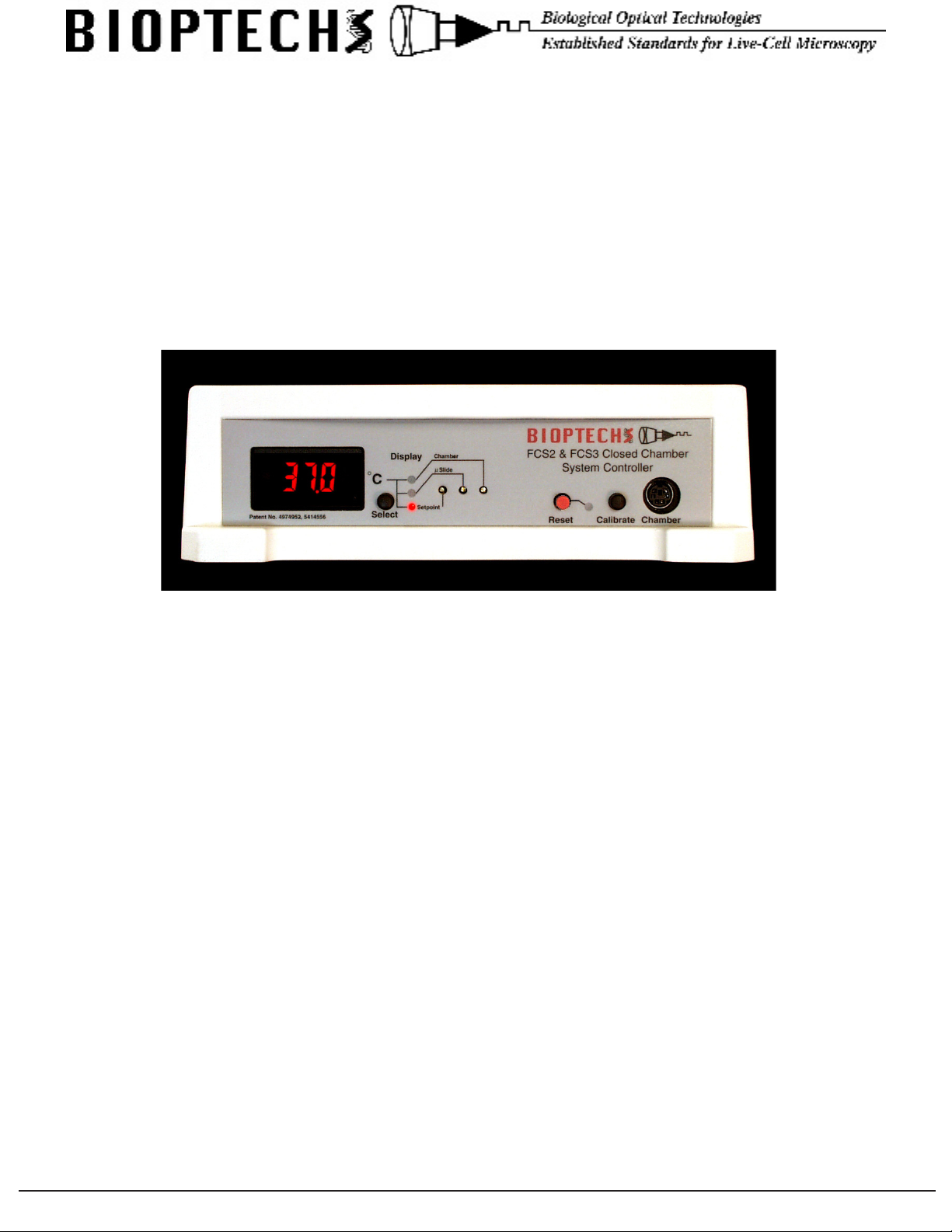
Front Panel of FCS2 & FCS3 Controller
Figure 1
Control Interface Descriptions:
Numeric Display should be illuminated when the controller is turned on. If it does not light, check the main power source then the
fuse block located in the power input module where the AC power cord plugs in.
Display Selector is the black button adjacent to the display. It selects the source of the information displayed. When the controller
is turned on, the default condition is to display the setpoint value indicated by the red light adjacent to the word Setpoint. The button
selects one of a sequence of display options. This button can be pressed at any time and has no effect on the temperature regulation
functions of the controller.
Display Lights indicate the source of the value displayed on the numeric display.
Setpoint is adjusted by a potentiometer accessible with the 2.5mm screwdriver provided. To adjust the setpoint set the numeric
display to Setpoint, then adjust the potentiometer to the desired value. If you need to change the setpoint value during your
experiment on a routine basis there is a remote setpoint jack on the back of the controller. See Remote Setpoint.
Slide is the location where the calibration of the circuit reading the Microaqueduct Slide can be adjusted.
Chamber is the location where the calibration of the circuit reading the Chamber can be adjusted.
Reset (Red Button) resets the controller if the alarm sounds. Note: If the alarm went off there must have been a reason. Check the
chamber before resetting the controller.
Calibrate substitutes precision resistors into the circuit that reads the thermistors so that calibration adjustments can be made to a
known value.
Chamber is a six pin mini DIN connector where the FCS2 or FCS3 is plugged in.
3560 Beck Road • Butler, PA 16002 • Voice: 724-282-7145 • Fax: 724-282-0745 • E-mail: info@bioptechs.com • Web: www.bioptechs.com
Page 2
3560 Beck Road • Butler, PA 16002 • Voice: 724-282-7145 • Fax: 724-282-0745 • E-mail: info@bioptechs.com • Web: www.bioptechs.com
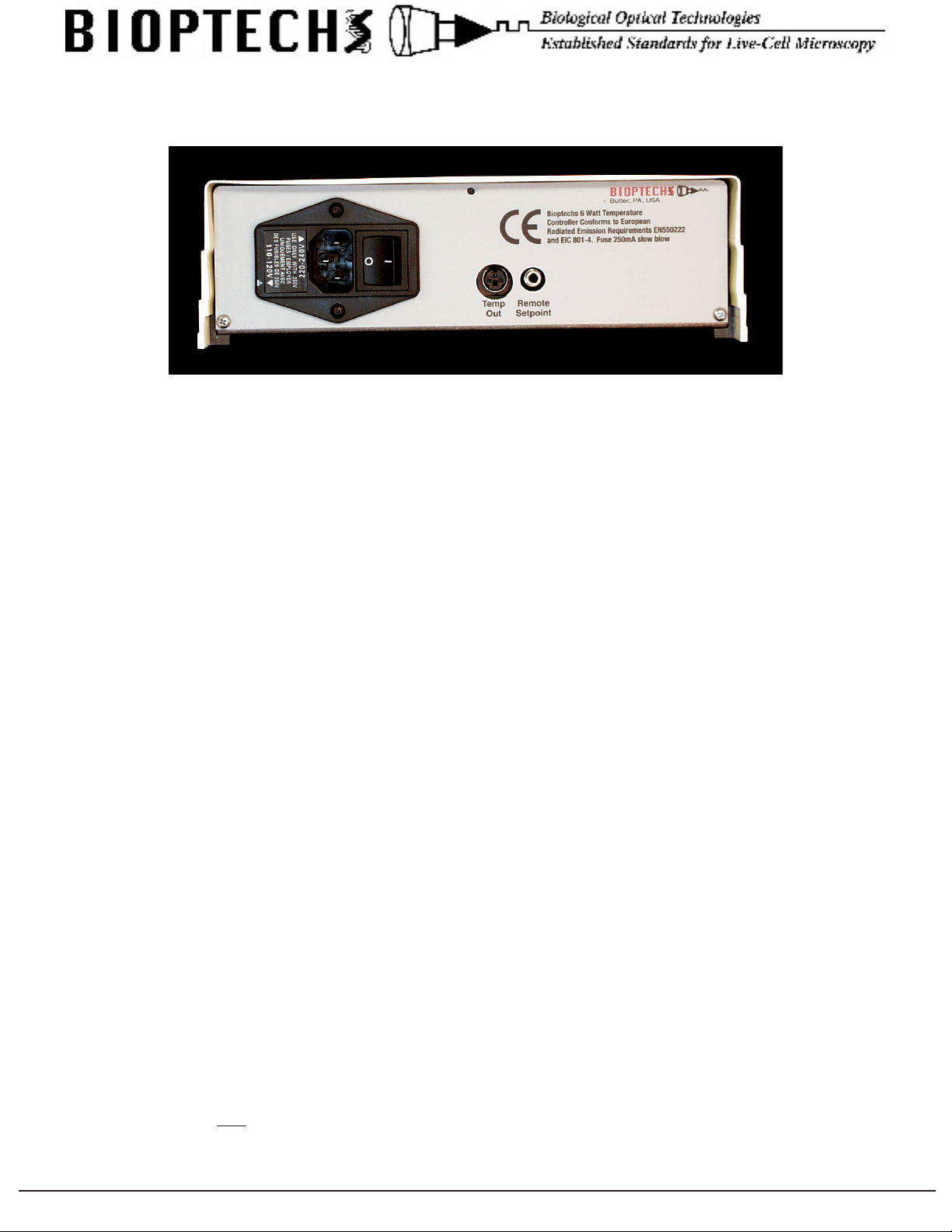
Back Panel of the FCS2 & FCS3 Controller
Figure 2
AC Power line input, power switch, voltage selector, and fuses are all incorporated in the AC Power Input Module. The
controller can operate between 90 - 260V 50-60Hz, or a 24V battery can be used as an alternate power supply. The fuse
carrier contains two 0.5A slow blow fuses. The fuses can be accessed by prying the fuse block out of its socket with a small
screwdriver wedged under the small slot in the opening of the AC line receptacle. When replacing the fuse block, make sure to
align the arrow on the outside of the fuse block with the closest voltage value to your supply line voltage:
• For 90-130 supply line voltage place the fuse block with the arrow pointing to 110-120V.
• For 180-260 supply line voltage place the fuse block with the arrow pointing to 220-240V.
Temp Out is a voltage output direct from two instrument ampliers reading the thermistors from channel A and B.
The output from this socket is temperature / 10. 37.0°C = 3.70 Volt DC.
The left pin is channel A, center pin is channel B, and right pin is ground.
Remote Setpoint is an analog input that allows the user to set the controllers setpoint from an external DC source. The sleeve is
earth ground. A DC voltage can be applied to the tip of this jack equal to temperature /10. i.e.: 28.5°C = 2.85 Volt. When the jack is
inserted into the controller it will automatically switch to the jacks value. When removed it will default to the setting on the front of
the controller. Use for programming or cycling operating temperatures.
Controller Operation:
1. Turn the unit on using the main on-off switch located on the rear panel. The Chamber need not be plugged in at this time.
All further adjustments are made on the front panel.
2. Set the display switch to the “SET” position. Insert the enclosed screwdriver into the hole marked Setpoint and adjust the
controller to the desired setpoint.
3. Set the display to the “Slide” or “Chamber” position. The LCD will display a number between -1.8 and -4.2. This is normal.
4. Press the black button labeled “CALIBRATE” and make sure the display reads 26.6°C when “Slide” is selected and 25.0
when “Chamber” is selected. If adjustment is necessary, turn the corresponding screws in the adjustment holes with the
enclosed screwdriver. CW = increase, CCW = decrease.
5. Turn the controller off.
6. With the chamber loaded, plug the chamber into the controller. DO NOT plug the chamber into the controller unless it is
either loaded or both slide contact wires are restricted from coming in contact with the base.
7. When the controller is turned on and the display switch is set to “Slide” or “Chamber” it will read the ambient temperature,
then slowly begin to rise until it reaches setpoint temperature. We recommend leaving the display switch in the “Slide”
position because it is the closest representation of the cell temperature.
Special Notes:
There is a safety cut-off circuit that protects the cells if the microaqueduct drops below 0.9°C from the setpoint after reaching
setpoint minus 0.9°C. Only during a cold start will the safety cut-off circuit ignore the out-of-range condition. This safety circuit
will shut off power to the slide circuit only and sound the alarm. If the alarm sounds, the user should correct the problem and
press the red reset button located next to the red LED.
3560 Beck Road • Butler, PA 16002 • Voice: 724-282-7145 • Fax: 724-282-0745 • E-mail: info@bioptechs.com • Web: www.bioptechs.com
Page 3

The alarm may sound as a result of the following conditions:
• Perfusion rate exceeds the rate which temperature stability can be maintained. To correct, press the red reset button
as soon as the alarm sounds. This will reset the logic back to cold start up mode. Setpoint temperature will return
within 15-20 seconds.
• An interruption in AC line power may cause the logic levels to change state.
• Physical displacement of the thermistor from the microaqueduct surface.
Note: The thermistor that regulates the chamber frame is sealed internally eliminating accidental displacement. Therefore,
there is no need for an alarm on the chamber frame circuit.
Chamber Loading
Your chamber has been inspected prior to packaging and is ready to use when you receive it. The chamber is shipped assembled
and should be opened using the following procedure.
Rotate the large knurled ring in the base of the chamber clockwise until it stops. This will release and disengage the chamber
top. Hold the white portion of the chamber while simultaneously (using thumb and forenger) rotating CCW the two smaller
knurled nuts located on either side of the black electrical contact unit. This will remove the black portion which contains sensitive
electronics so that they can remain dry. You now have the basic components of the chamber separated. Continue with the following
directions:
Directions for Closed System Use: (see drawing for part identication)
• Attach perfusion tubing to the inlet and outlet ports of the chamber. Bioptechs recommends 1/16” Tygon #2275
tubing for best biocompatibility and ease of use. See perfusion drawing.
• Turn the top of the chamber (white) upside-down. Place the upper gasket (.75mm thick) into the recess while
aligning the perfusion clearance holes with the perfusion tubes.
• Place the microaqueduct slide on the upper gasket so that it is aligned with perfusion tubes (grooved side up).
• Place the lower gasket (0.1mm - 1.0mm thick) onto the microaqueduct slide and press around the perimeter creating
a seal.
• Perfuse some media through the perfusion port producing a bead on the surface of the slide to displace air trapped in
the line.
• Lower the coverslip with cells onto the bead until it is resting on the gasket.
• Place the closure assembly on top of this stack while aligning the black electrical connector with the oval slot in the
chamber top. Maintain a gentle pressure while turning the chamber over so that it is right side up then can observe
as the four paws engage the top through the depressions about the perimeter. Turn the large knurled ring counterclockwise until tight. This will symmetrically tighten and seal the chamber.
• For applications involving rapid perfusion, a drop of immersion oil can be placed at the point where the base of the
chamber meets the coverslip in the exposed aperture of the chamber. This drop will be drawn in by capillary action
and enhance thermal conductivity to the coverslip. Place a light lm of immersion oil on the at surface of the
surface probe to enhance thermal conductivity.
• Place the black power/sensor connector back on the two threaded posts and symmetrically rotate CW (using thumb
and forenger) the two knurled nuts onto the post. Make sure the spring wires make contact with the bus bars on the
surface of the microaqueduct slide.
• It is important that the at side of the surface probe is making uniform contact with the microaqueduct slide because
the feedback loop that controls the microaqueduct temperature is reliant on this thermal contact point.
• Plug the FCS2 Chamber into the controller (6 Pin mini DIN).
• The display can be switched between Set, Slide and Chamber at any time to monitor temperature without interfering
with the regulation. If the Chamber was preheated it will come up to temperature in about 1 minute, otherwise it
will take longer.
• The Chamber should now be mounted onto the microscope adapter in the stage.
• The vertical portion of the drain tubing which extends down from the stage to your waste receptacle will create a
siphon and form negative pressure in the chamber. This negative pressure will cause the coverslip to ex. This can
be eliminated by breaking the siphon at a point equal to the height of the specimen with a “T” tting.
3560 Beck Road • Butler, PA 16002 • Voice: 724-282-7145 • Fax: 724-282-0745 • E-mail: info@bioptechs.com • Web: www.bioptechs.com
Page 4

3560 Beck Road • Butler, PA 16002 • Voice: 724-282-7145 • Fax: 724-282-0745 • E-mail: info@bioptechs.com • Web: www.bioptechs.com
Cleaning:
The various components of the chamber can be cleaned as follows:
1. The closure assembly and power/sensor connector do not come into contact with the specimen and should only be cleaned
with a damp cloth or alcohol wipe. DO NOT immerse either one in liquid.
2. Coverslips and gaskets should be hand cleaned and short cycle autoclaved before use. Do not use alcohol on gaskets.
3. The white plastic (Delrin) portion of the FCS2 will be in uid communication with the specimen and can be autoclaved
at 120°C for 15 minutes.
High Numeric Aperture Use:
If you are using high numeric aperture (immersion) objectives with high N.A. dishes, it will be necessary to regulate the
temperature of the objective as well. This is due to the fact that the optical coupling medium, oil, glycerin or water also has a
thermal coupling effect. In this case, a Bioptechs, Inc. Objective Heater and an Objective Heater Controller will be necessary
for uniform temperature across the eld.
Objective Heater Description:
The Bioptechs Objective Heater is an adjustable, thin lm, size and shape compliant, heating band and temperature sensor
assembly attached to a linear translator. This device attaches to the objective and plugs into a separate Temperature Controller,
which regulates the objective temperature within 0.1°C of SETPOINT.
Continual Perfusion with the Micro-Perfusion Pump:
Bioptechs recommends the FCS2 Micro-Perfusion Pump due to its smooth ow prole in slow ow applications. If dual ow
is needed there is also a PC interface board and program that enables alternate control of two pumps to regulate the acceleration
and run time of each. The Micro-Perfusion Pump Controller (PC interface) is ideal for changing concentrations of media.
3560 Beck Road • Butler, PA 16002 • Voice: 724-282-7145 • Fax: 724-282-0745 • E-mail: info@bioptechs.com • Web: www.bioptechs.com
 Loading...