

Page 1
3560 Beck Road • Butler, PA 16002 • Voice: 724-282-7145 • Fax: 724-282-0745 • E-mail: info@bioptechs.com • Web: www.bioptechs.com
Delta T4 Culture Dish System Instructions
Caution: Read Carefully Before Use!
The System is comprised of three main components: a temperature controller, a stage adapter, and the Delta T Dish. It utilizes a new and
improved technology that is much faster and more accurate than traditional peripheral stage warmers. The controller has a fast learning curve
to anticipate changes in the dish temperature due to perfusion or surface evaporation while regulating temperature and compensating for
entropy. The fast response capability of this system enables control features previously not possible with conventional peripheral systems.
Therefore, it is highly recommended that you read and fully understand these instructions before use.
Before You Begin:
• Check to make sure there is no visible damage in shipment and save all packing materials.
• The Controller box should contain; controller, power cord, 2.5mm screwdriver, 6’ BNC cable, 1/8” jack, and 3 pin mini DIN
connector.
• Check the packing list and call your supplier if there are any discrepancies.
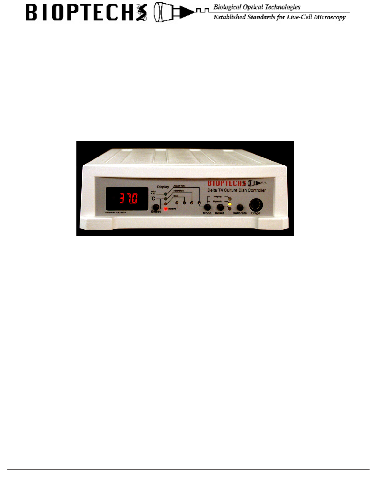
Figure 1
Control Interface Descriptions
Numeric Display should be illuminated when the controller is turned on. If it does not light, check the main power source then the fuse block
located in the power input module where the AC power cord plugs in.
Display Selector is the black button adjacent to the display. It selects the source of the information displayed. When the controller is turned on, the
default condition is to display the setpoint value indicated by the light adjacent to the word Setpoint. The button selects one of a sequence of display
options. This button can be pressed at any time and has no effect on the temperature regulation functions of the controller.
Display Lights indicate the source of the value displayed on the numeric display.
Setpoint is adjusted by a potentiometer accessible with the 2.5mm screwdriver provided. To adjust the setpoint make sure the numeric display is
set to Setpoint, then adjust the setpoint to the desired value. See adjusting setpoint value. If you need to change the setpoint value during your
experiment on a routine basis there is a remote setpoint jack on the back of the controller. See Remote Setpoint.
Dish is the location where the calibration of the dish thermistor reading circuit can be adjusted.
Reference is the location where the calibration of the thermistor reading circuit can be adjusted.
Adjust Volts is the location where the non-dynamic voltage adjustment is made. This is the energy value sent to the dish when the controller is in
Imaging Mode. Adjust Volts must be selected for the display and the Mode switch must be pressed for this value to appear. The display will show
a number that is 10 times the actual voltage value being sent to the dish. Adjustments can be made to this value by turning the small screw located in
the hole corresponding to Imaging Volts.
Mode button changes the mode of operation of the controller from dynamic feedback control to a xed voltage set by the Adjust Volts setting.
When the controller is in Dynamic mode, the amber LED will be lit next to the mode switch. When the controller is in Imaging mode, the green LED
will light. If the controller is in Imaging mode as a result of pressing the mode switch, only the green LED will light. If the controller is in Dynamic
mode and a TTL voltage is applied to the BNC jack on the back of the controller, both the amber and the green LEDs will light. Caution! Make sure
that the controller is not left in the Imaging mode for longer than 30 seconds. This will not damage the controller but if the temperature in the dish
deviates more than the error margin during this time, the alarm will sound and the controller will ignore all the safety interrupts. The controller will
continue to supply the constant voltage to the dish until the controller is returned to the Dynamic mode.
3560 Beck Road • Butler, PA 16002 • Voice: 724-282-7145 • Fax: 724-282-0745 • E-mail: info@bioptechs.com • Web: www.bioptechs.com
Page 2
Reset (Red Button) resets the controller to the cold start condition and enters the energy value used in Adjust Volts as a starting regulation value.
It is to be used when any of the following conditions occur:
1. Immediately before placing a new dish into the stage adapter if you want to change dishes without turning off the controller.
2. Immediately after placing a new dish into the stage adapter. This is insurance that the controllers learning curve did not wonder during the few
seconds it takes to insert a dish. Dish exchanges should not take more than 10 seconds.
3. When the alarm goes off and the red LED lights next to the Reset button. Note: If the alarm went off there must have been a reason. Check the
dish before resetting the controller.
Calibrate substitutes precision resistors into the circuit that reads the thermistors so that calibration adjustments can be made to a known value.
Stage is a six pin mini DIN connector where the stage adapter is plugged in.
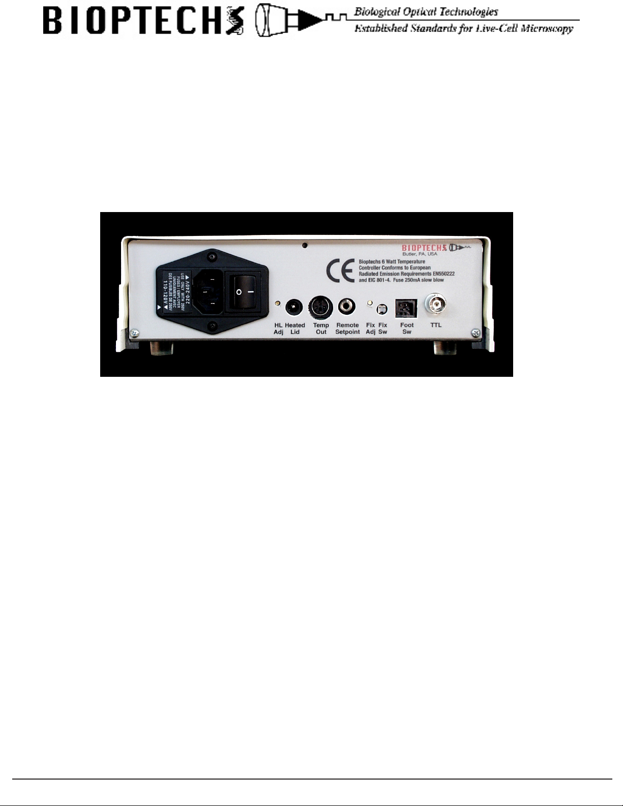
Back Panel of the Delta T4 Controller
Figure 2
AC Power line input, power switch, voltage selector, and fuses are all incorporated in the AC Power Input Module. The controller can
operate between 90 - 260V 50-60Hz, or a 24V battery can be used as an alternate power supply. The fuse carrier contains two 0.5A slow
blow fuses. The fuses can be accessed by prying the fuse block out of its socket with a small screwdriver wedged under the small slot in
the opening of the AC line receptacle. When replacing the fuse block, make sure to align the arrow on the outside of the fuse block with the
closest voltage value to your supply line voltage:
• For 90-130 supply line voltage place the fuse block with the arrow pointing to 110-120V.
• For 180-260 supply line voltage place the fuse block with the arrow pointing to 220-240V.
Heated Lid Adjustment is the adjustment for the voltage sent to the Heated Lid. Its range is from 0 to 5 V DC. The nominal voltage is 2.5 V. This
voltage should be measured at the Heated Lid with an external meter. It should be adjusted to a value just above the condensation point.
Heated Lid is the location to plug in the Bioptechs Heated Lid.
Temp Out is a voltage output direct from two instrument ampliers reading the thermistors from channel A and B.
The output from this socket is temperature /10. 37.0°C = 3.70 Volt DC. Left pin is channel A, center pin is channel B, and right pin is ground.
Remote Setpoint is an analog input that allows the user to set the controllers setpoint from an external DC source. The sleeve is earth ground. A DC
voltage can be applied to the tip of this jack equal to temperature /10. i.e.: 28.5°C = 2.85 Volt. When the jack is inserted into the controller it will
automatically switch to the jacks value. When removed it will default to the setting on the front of the controller. Use for programming or cycling
operating temperatures.
Fixing Adjustment allows the user to adjust the voltage sent to the dish when the Fixing Switch is depressed. Range from operating temp to 97°C.
Fixing Switch is provided so that cells can be xed on the stage of the microscope. It can also be used for heat shock experiments. The switch is
recessed so that it is not actuated by mistake. Caution! This switch should be used when you intentionally want to overheat your cells. It provides a
nearly instantaneous heat shock to the dish.
TTL is a BNC connection used to change the mode of operation of the controller from a remote source such as a computer or slave from a shutter
trigger. The default condition of the controller is dynamic control. To change to Imaging mode, apply a TTL logic high and hold to this BNC. The
controller will remain in Imaging mode as long as the TTL condition remains high as indicated by the LED on the front panel.
3560 Beck Road • Butler, PA 16002 • Voice: 724-282-7145 • Fax: 724-282-0745 • E-mail: info@bioptechs.com • Web: www.bioptechs.com
Page 3

3560 Beck Road • Butler, PA 16002 • Voice: 724-282-7145 • Fax: 724-282-0745 • E-mail: info@bioptechs.com • Web: www.bioptechs.com
Delta T4 Controller Operation
Instructions:
1. Without any peripherals plugged into the controller, turn the unit on using the main on-off switch located on the rear panel adjacent to the
power cord.
2. Set the display to “DISH”. The temperature display will read a number between -3.7 and -4.2. Press and hold the black button labeled
“CALIBRATE” and make sure the display reads 25.0°C. If adjustment is necessary, turn the corresponding screw in the adjustment
hole with the enclosed screwdriver. CW = increase, CCW = decrease. Repeat this procedure with the display switch set to the “REF”
position.
3. Set the display to “SETPOINT”. Insert the enclosed screwdriver into the opening marked “SETPOINT” and set the controller to read a
value 2.0°C less than the desired setpoint. Note: The surface probe reads faster than the cell surface because it is not immersed in liquid
and is in direct contact with the heating surface. This is to your advantage.
4. Plug in the stage adapter without a dish. With the display set to DISH it will read room temperature.
5. You now have a choice; you can either turn the controller off for a minute before loading a dish with cells or leave the controller on and
remember to press the RESET button immediately before placing a dish into the stage adapter.
6. Wet the metallic surface of the thermistor located in the aperture of the stage adapter with a light lm of immersion oil. Place a dish into
the stage adapter and secure it by turning the dish 15° CW.
7. If a dish containing cells is still warm from prior incubation, the Delta T4 will reestablish temperature in about 15 seconds. If
the contents of the dish are at room temperature, the Delta T4 will require ≈2 minutes to reach setpoint. The dish should contain
approximately 2ml of media for proper operation. Cells can be then plated directly on the microscope by pipetting into the
instantaneously warmed dish. Do not power up with a dry dish.
8. Adjust the SETPOINT by immersing the reference thermistor into the dish and read its temperature by setting the display to
“REFERENCE”. During this time we recommend oating some mineral oil on top of the media to eliminate the effects of surface
evaporation. Allow the thermistor time to equilibrate before reading its value. Compare the reference temperature to the regulated
temperature and make the appropriate adjustments to the SETPOINT value. Alternate method if you are working at 37°C; place a
Bioptechs liquid crystal temperature indicator dot into the dish and adjust the SETPOINT until it turns green.
9. Turn the controller off prior to removing the dish from the stage adapter to prevent the controller from attempting to regulate a
nonexistent load. This will cause the learning curve to go beyond reasonable values. If you forget to turn off the controller, you can
always press the RESET button to reset the learning curve.
Special Note:
If you are perfusing cells and the dish temperature deviates from setpoint more than the 0.9°C error window, an alarm will sound, current
will be shut off to the dish and a red light will come on next to the red reset button. To silence the alarm and resume heating, press the
RESET button. This will return the controller to cold startup mode and it will ignore the error window until the temperature again
reaches setpoint minus 0.9°C. You can use the RESET button at any time to reset the controller’s learning curve.
Use of the Delta T4 in Narrow Depth of Field Applications:
The Dynamic control characteristics of the Delta T4 enable it to almost instantaneously compensate for temperature changes that may occur
in the dish due to perfusion, surface evaporation or other ambient conditions. The sensitivity of the controller, 0.1°C, coupled with the speed
and intensity of the controller’s response, may cause the coverslip to ex a detectable amount during narrow depth of eld imaging. The
controller is equipped with a circuit that bypasses the dynamic temperature control mode and permits you to temporarily send a constant DC
current to the dish to eliminate the possibility of an abrupt change of energy occurring as might happen in dynamic mode. This prevents Zaxis displacement of the specimen during imaging.
The controller can be switched from its default Dynamic control mode to Imaging mode by several means:
1. Pressing the mode button on the front of the controller
2. Pressing the optional footswitch
3. TTL communication from an external trigger such as a acquisition host or slave from a TTL shutter trigger
Operate the Delta T4 in the auto (dynamic) mode when you are not scanning or acquiring images.
When you intend to acquire an image activate the Imaging mode. The value of the DC current can be adjusted with the potentiometer labeled
Adjust Volts. A good starting point is 2.7V shown as 27.0 on the display. After adjusting the Adjust Volts setting, return the display to the
Dish position and check to see that the value you have entered is adequate to maintain the setpoint value for at least 15 seconds. Make sure
the controller is returned to the auto mode immediately after the image is acquired.
3560 Beck Road • Butler, PA 16002 • Voice: 724-282-7145 • Fax: 724-282-0745 • E-mail: info@bioptechs.com • Web: www.bioptechs.com
Page 4

Stage Adapter
The stage adapter provides support for the dish, electrical contacts, and the surface temperature probe. Make sure the adapter is rmly
attached to the scope. When mounting a dish, make sure there is a lm of immersion oil on the surface probe to enhance thermal
conductivity. To mount a dish, place the dish into the stage adapter by matching the tabs on the dish with the openings in the stage
adapter. Then, while applying sufcient downward force so as to compress the contacts in the base of the adapter, rotate the dish 15°
CW until it comes to rest under the opposing metal tabs. Dishes are removed by rotating the dish 15° CCW then lifting out of the
retainer.
• A pair of mounting holes on either side of the dish aperture are provided to attach perfusion devices.
• There is a thermistor on the top of the terminal cover which can be read by setting the display to the “REFERENCE” position.
Note: If corrosion is present on the electrical contacts, it should be cleaned immediately. The contacts can corrode if exposed to
media in the presence of an electrical current. Corrosion on the stage adapters is preventable and not covered under warranty.
Care and Cleaning:
The stage insert and controller can be cleaned by hand wiping with mild soap and water or alcohol but do not immerse or autoclave. The
stage insert should remain dry at all times. If liquids are spilled on or into the stage adapter they must be cleaned and the stage adapter
dried immediately!
Delta T Dishes
Delta T Dishes are made of a polystyrene ring which has a specially coated clear glass substrate bonded onto the bottom surface forming
a 2ml liquid containment structure having a 35mm OD which tapers down to a 23mm optical aperture. The glass substrate is available in
two thicknesses, 0.5mm for low N.A. and #1.5 coverslip for high N.A. applications. In standard production, the 0.5mm thick substrate is
bonded to a clear dish ring and shipped with clear lids. The #1.5 coverglass is available bonded to black and clear dish rings and shipped
with corresponding lids. All other characteristics of the dishes are identical. We recommend the use of black dishes for uorescence
applications.
The thickness of the dish can also be determined from the stock number on the dish package.
04200405 = 0.5mm thick clear
04200415B = #1.5 coverslip thickness / black
04200415C = #1.5 coverslip thickness / clear
*Custom congurations available upon request.
High Numeric Aperture Use:
If you are using high numeric aperture (immersion) objectives with high N.A. dishes, it will be necessary to regulate the temperature of
the objective as well. This is due to the fact that the optical coupling medium; oil, glycerin or water also has a thermal coupling effect.
In this case, a Bioptechs, Inc. Objective Heater and an Objective Heater Controller will be necessary for uniform temperature across the
eld.
Objective Heater Description:
The Bioptechs Objective Heater is an adjustable, thin lm, size and shape compliant, heating band and temperature sensor assembly
attached to a linear translator. This device attaches to the objective and plugs into a separate Temperature Controller, which regulates the
objective temperature within 0.1°C of SETPOINT.
Continual Delta T Perfusion with the Delta T Micro-Perfusion Pump:
The Delta T Micro-Perfusion Pump is shipped with dual channel tubing. When the tubing pair is stretched around the rollers on the
pump, the tube with the black band will have a slightly smaller ID yielding a slower uid transport capability. Attach the supply line
from your media to the barb on the input side of the black band pump tubing and another tube from the output side of this tube to the
selected irrigation port of the dish. Attach tubing from the aspiration port of the dish to the input side of the other pump tube and a line
from the output side of this pump tube to a waste container. Adjust the pump speed as needed for suitable perfusion rate.
3560 Beck Road • Butler, PA 16002 • Voice: 724-282-7145 • Fax: 724-282-0745 • E-mail: info@bioptechs.com • Web: www.bioptechs.com
 Loading...