

Page 1

MP30 and MP35 Specifications - 1 -
IMPORTANT SAFETY NOTICE
BIOPAC Systems, Inc. instrumentation is designed for educational and research
oriented life science investigations. BIOPAC Systems, Inc. does not condone the
use of its instruments for clinical medical applications.
Instruments, components, and accessories provided by BIOPAC Systems, Inc.
are not intended for the cure, mitigation, treatment, or prevention of disease.
The MP35/30 is an electrically isolated data acquisition unit, designed for
biophysical measurements.
Exercise extreme caution when applying electrodes and taking bioelectric
measurements while using the Biopac Student Lab with other external
equipment that also uses electrodes or transducers that may make electrical
contact with the Subject.
Always assume that currents can flow between any electrodes or electrical
contact points. In case of equipment failure, it is very important that significant
currents are not allowed to pass through the heart.
If electrocautery or defibrillation equipment is used, it is recommended that the
BIOPAC instrumentation be disconnected from the Subject.
Page 2

- 2 - BIOPAC Systems, Inc.
MP35/30 ACQUISITION UNIT
The MP35/30 data acquisition unit is the heart of the Biopac Student Lab PRO System. The MP35/30
has an internal microprocessor to control data acquisition and communication with the computer. The
MP35/30 unit takes incoming signals and converts them into digital signals that can be processed
with your computer. There are four analog input channels, one of which can be used as a trigger
input. You will need to connect the MP35/30 to your computer and connect electrodes, transducers,
and I/O devices to the MP35/30. You are encouraged to take a few minutes to familiarize yourself
with the MP35/30 prior to making any connections.
SYMBOLS — MP35
Symbol Description Explanation
TYPE BF
EQUIPMENT
Classification
Attention
Consult accompanying documents
On (partial)
Off (partial)
Turns MP35 on assuming AC300A
power adapter is powered by the mains
Turns MP35 off if but AC300A power
adapter remains powered by the mains
Direct current
USB
Direct current output
USB port
COMPLIANCE
SAFETY
The MP35 satisfies the Medical Safety Test Standards affiliated with IEC60601-1. The MP35 is
designated as Class I Type BF medical equipment
EMC
The MP35 satisfies the Medical Electromagnetic Compatibility (EMC) Test Standards affiliated with
IEC60601-1-2.
TYPES OF INPUT DEVICES
There are three types of devices that connect to the MP35/30: electrodes, transducers, and I/O
devices.
• Electrodes are relatively simple instruments that attach to the surface of the skin and pick up
electrical signals in the body.
• Transducers, on the other hand, convert a physical signal into a proportional electrical signal.
• Input/Output devices (I/O for short) are specialized devices like pushbutton switches and
headphones.
Visit www.biopac.com
for the latest product updates
Page 3
MP30 Hardware Guide - 3 -
SIMPLE SENSOR CONNECTORS
Regardless of the type of device connected, every sensor or I/O device connects to the MP35/30 using
a “Simple Sensor” connector. Simple Sensor connectors are designed to plugs only one way into the
MP35/30, so you don’t have to worry about plugging things in upside down or into the wrong socket.
• Electrodes, transducers, and the pushbutton switch all connect to the channel input ports on
the front panel of the MP35/30.
• Headphones and the stimulator connect to the “Analog out” port on the back panel of the
MP35/30.
• MP35 only: A digital device may connect to the “I/O Port” on the back panel
• MP35 only: A trigger device may be connected to the “Trigger” port on the back panel.
FRONT PANEL
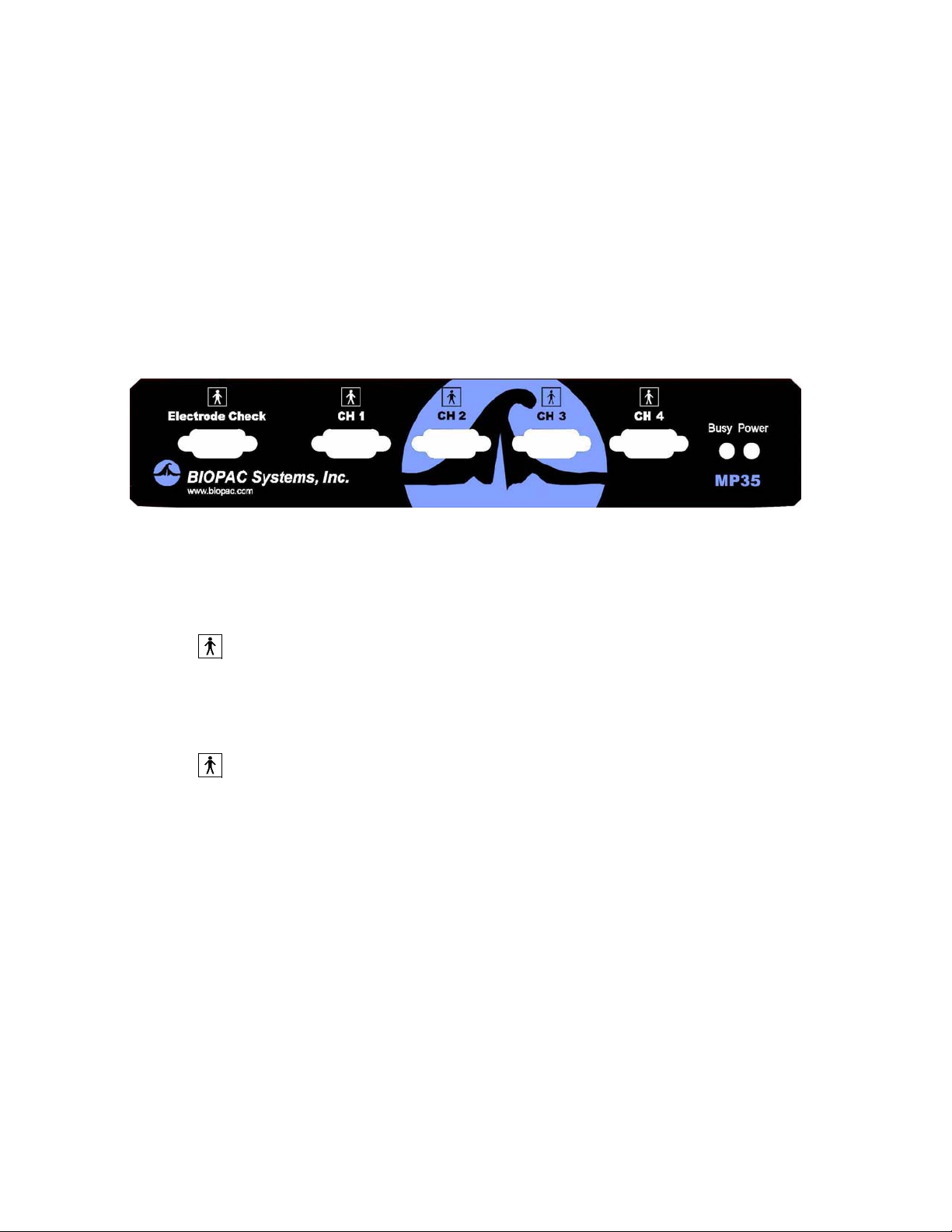
Front Panel, MP35
The front panel of the MP35/30 has an electrode check port, four analog input ports, and two status
indicators.
Electrode Check
•
The Electrode Check port is a diagnostic tool used with the BSL PRO software to
determine if the electrodes are properly attached to the subject. See page Error! Bookmark
not defined..
Input ports: CH 1, CH 2, CH 3, and CH 4
•
The inputs on the MP35/30 acquisition unit are referred to as Channels. There are four 9pin female analog input ports on the front of the MP35/30. The Biopac Student Lab Lessons
software will always check to see that you have the proper sensors connected to the
appropriate channel.
Status indicators
• The Busy status indicator is activated when the MP35/30 is acquiring data and also during the
first few seconds after the MP35/30 is powered on to indicate that a self-test is in progress.
(When the MP35/30 passes the power-on test, the Busy light will turn off.)
• The Power status indicator is illuminated when the MP35/30 is turned on.
Page 4
- 4 - BIOPAC Systems, Inc.
BACK PANEL
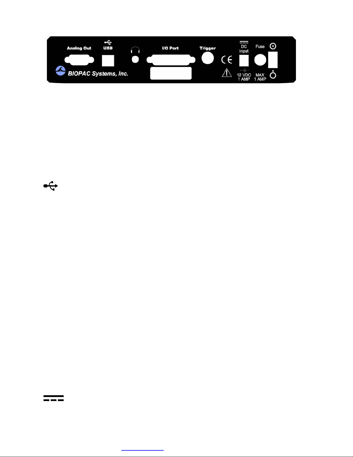
Back Panel, MP35
The back panel of the MP35 has an analog output port, a USB port, an I/O Port, a Trigger Port, a DC
input, a fuse holder, and a power switch, and the unit’s serial number.
The back panel of the MP30 has an analog output port, a serial port, a DC input, a fuse holder, and a
power switch, and the unit’s serial number.
Analog Out port
There is one 9-pin male “D” analog output port on the back of the MP35/30 that allows signals to be
amplified and sent out to devices such as headphones.
USB port (MP35 only)
The MP35 connects to the computer via a USB Port, located just below the word USB.
• Uses a standard USB connector.
• Should only be used to connect the MP35 to a PC or Macintosh.
Serial port (MP30 only)
The MP30 connects to the
computer via a serial port, located just below the word Serial.
• Uses a standard MINI DIN 8 connector.
• Should only be used to connect the MP30 to a PC (with ISA or PCMCIA card) or Macintosh.
Headphone Output (MP35 only)
Accepts a standard (1/4” or 6.3mm) stereo headphone jack.
I/O Port (MP35 only)
• Accepts a DB 25 Female connector.
• Input/Output port used to connect digital devices to the MP35.
Trigger Input (MP35 only)
• Accepts a male BNC connector.
• Input port used to send trigger signals from another device to the MP35.
• Used to synchronize MP35 units when more than one MP35 is used.
DC Input
Use the DC Input to connect a battery, AC/DC converter or other power supply to the
MP35/30.
Visit www.biopac.com
for the latest product updates
Page 5

MP30 Hardware Guide - 5 -
•
The power supply requirements for the MP35/30 are 12 VDC @ 1 Amp. Only use the
AC300A power adapter with the MP35. The AC300A is a 12 VDC @ 1.25 Amp power
supply adapter that can connect to any mains rated as 100-250 VAC @ 50/60Hz, 40VA.
• The receptacle is configured to accept a “+” (positive) input in the center of the connector and
a “-” (negative) input on the connector housing.
Fuse holder
The fuse holder contains a fast-blow fuse that helps protect the MP35/30 from shorts on its power,
analog, and digital I/O lines. The MP35 uses a 1.0 amp fast-blow fuse and the MP30 uses a 2.0 amp
fast-blow fuse.
• To remove the fuse, use a screwdriver to remove the fuse cover located below the word Fuse.
Power switch
•
•
ON position — powers up the MP35/30
OFF position — cuts the flow of power to the MP35/30
CLEANING PROCEDURES
Be sure to unplug the power supply from the MP35/30 before cleaning. To clean the MP35/30, use a
damp, soft cloth. Abrasive cleaners are not recommended as they might damage the housing. Do not
immerse the MP35/30 or any of its components in water (or any other fluid) or expose to extreme
temperatures as this can damage the unit.
Page 6

- 6 - BIOPAC Systems, Inc.
SPECIFICATIONS
Specification MP35 Unit MP30 Unit
Front Panel
ELECTRODE CHECKER
Resistance Range (Vin+ and
Vin- to GND)
ANALOG INPUTS
Number of channels
SAMPLE RATE
Maximum
Minimum
Trigger Input
Threshold
A/D resolution (before digital
filtering)
Signal to noise ratio > 90 dB (nominal) > 90 dB
Voltage resolution Gain
dependent
Input voltage range (Gain
dependent)
Input accuracy ±0.01% of Full Scale Range (FSR) ±0.05% FSR
Input protection; current limited ± 1 mA/V ± 1 mA/V
Maximum Input Voltage
(between Vin+ and Vin-)
Differential Input Impedance
(between Vin+ and Vin-)
Filters (automatic or user
adjustable)
Common Mode Input
Impedance (between Vin+/Vinand GND)
DC
AC (50/60 Hz)
Gain ranges (automatic preset
or user adjustable)
Baseline adjustment
(automatic or user adjustable)
Electrode offset potential
tolerance
Back Panel
ANALOG OUTPUT
Number of channels
D/A resolution
Accuracy
Output impedance
Output voltage
Output drive current
0-100 KΩ
0-100 KΩ
4 isolated (front panel CH 1–CH 4),
2 unisolated (auxillary)
100K samples/second
1 samples/second
Analog or digital channel
Adjustable threshold; Positive or
Negative Trigger
4 (front panel CH 1–CH 4)
2K s/s (8K aggregate on four ch.)
1 samples/second
CH 4 input only
Adjustable threshold; Positive or
Neg
a
tive Threshold
24-bit 10-bit
1.192 microvolts /bit (Gain 10) to
0.024 nanovolts /bit (Gain 50,000)
0.400 microvolts/bit (Gain 100) to
0.200 millivolts/bit (Gain 25,000)
400 microvolts to 2.0 Volts p-p 4.0 millivolts to 0.2 Volts p-p
2V p-p 130mV p-p
2 MΩ 2 MΩ
3 two-pole IIR digital filters per
channel
11 MΩ
1,000 MΩ
3 two-pole IIR digital filters per
channel
11 MΩ
1,000 MΩ
10 – 50,000 100 – 50,000
Gains 10, 20, and 50: ±100mV
±10mV all Gains
Gains 100 to 50,000: ±10mV
Gains 10, 20, and 50: ±2V
±70 mV all Gains
Gains 100, 200, 500: ±200mV
Gains 1,000 to 50,000: ±80mV
1
12 bits
±0.0125% of FSR
50Ω
0 - 4.096 V
±10 mA maximum
1
8 bits
±0.2% of FSR
50Ω
0 - 5.000 V
±100 mA maximum
Visit www.biopac.com
for the latest product updates
Page 7

MP30 Hardware Guide - 7 -
Specification MP35 Unit MP30 Unit
SERIAL INTERFACE
Transmission type
Transmission rate
HEADPHONE (MP35 only)
I/O PORT (MP35 only)
TRIGGER (MP35 only)
DC INPUT
FUSE 1.0 amp fast-blow fuse 2.0 amp fast-blow fuse
MP UNIT
Dimensions
Weight
USB
Type 2.0 full speed
Drives low-impedance standard
stereo headphones
8 TTL compatible inputs and 8 TTL
compatible outputs
TTL compatible input and
synchronization port
Power input; requires 12 VDC @ 1
Amp. Use the AC300A 12 VDC @
1.25 Amp power supply adapter to
connect to any mains rated as 100250 VAC @ 50/60Hz, 40VA.
7 cm x 29 cm x 25 cm
1.4 Kg
RS422-clocked asynchronous
524,000 bits per second (KBPS)
N/A – MP35 only
N/A – MP35 only
N/A – MP35 only
Power input; requires 12 VDC @
1 Amp. Use the AC300A 12 VDC
@ 1.25 Amp power supply
adapter to connect to any mains
rated as 100-250 VAC @
50/60Hz, 40VA.
7 cm x 29 cm x 25 cm
1.4 Kg
Page 8
- 8 - BIOPAC Systems, Inc.
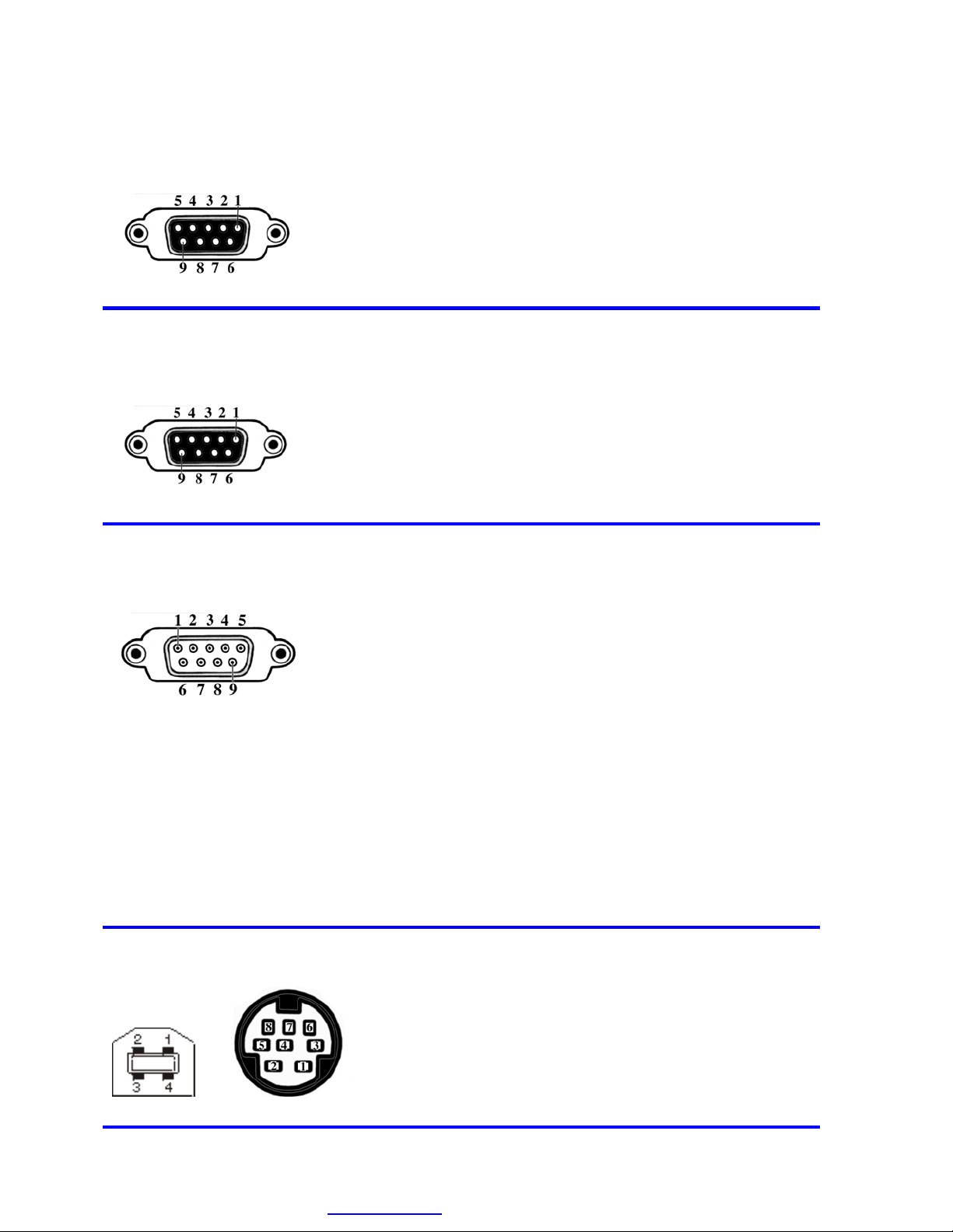
MP UNIT PIN-OUTS
Electrode Check — Front Panel
9-PIN FEMALE DSUB
Pin MP35 and MP30
2 Vin+ Electrode connection
3 GND
4 Vin- Electrode connection
MP Input — Front Panel
CH 1, CH 2, CH 3, CH 4
9 PIN FEMALE DSUB (1 of 4)
MP Analog Output — Back
Panel
9 PIN MALE DSUB
Pin MP35 MP30
1 Shield drive Shield drive
2
Vin+ Vin+
3
GND GND
Vin− Vin−
4
5
Shield drive Shield drive
6
7
8
+5 V (100 mA max aggregate) +5 V (50 mA max)
ID resistor lead 1; I2C SCL ID resistor lead 1 (+5 V)
ID resistor lead 2; I2C SDA ID resistor lead 2
9 −5 V (100 mA max aggregate) −5 V (50 mA max)
Pin MP35 MP30
1 Buffered AC output Buffered AC output
Z out = 2,200 µF Cap Z out = 2,200 µF Cap
V out range MP35: (+/- 2.0 V) MP30: (+/- 2.5 V)
2 Buffered DC output Buffered DC output
Z out = 50 Ω Z out = 50 Ω
V out range MP35: (0 to 4.096 V) MP30: (0 to 5 V)
3 GND GND
4 +5.0 V (100 mA max) +7.5 V (100 mA max)
5 Buffered digital output Unbuffered DC output
Z out = 1 kΩ Z out = 1 kΩ
V out range (0 to 5 V) V out range (0 to 5 V)
6 +12 V (100 mA max) Not used
2
C SCL Not used
7 I
8 I2C SDA Not used
MP Serial Connector — Back
Panel
MP35 MP30
Visit www.biopac.com
9 Not used Not used
Pin MP35 MP30
1 +5 Digital Output 1
2 -Data Digital Output 2
3 Data + Digital Output 3
4 GND Digital Output 4
5 n/a GND Unisolated
6 n/a GND Unisolated
7 n/a RS-232-RX
8 n/a +5 V Unisolated
for the latest product updates
Page 9

MP30 Hardware Guide - 9 -
MP35 Only
MP UNIT PIN OUTS continued
Pin
1 Digital Output 1
I/O Port — MP35 Back Panel
DSUB 25 (male)
1 2 3 4 5
6 7 8 9
10 11 12 13
2 Digital Output 2
3 Digital Output 3
4 Digital Output 4
5 GND Unisolated
14 15 16 20 21 22
Note: BSL v 3.7.0 does not support
17 18 19
Pins 7, 9, 18, 19, 20 and 21.
23 24 25
6 GND Unisolated
7 RS-232-RX
8 +5 V Unisolated
9 I
2
C-SDA
10 Digital Input 1
11 Digital Input 2
12 Digital Input 3
13 Digital Input 4
14 Digital Output 5
15 Digital Output 6
16 Digital Output 7
17 Digital Output 8
18 Analog Input — Right
19 Analog Input — Left
20 RS-232-TX
21 I
2
C-SCL
22 Digital Input 5
23 Digital Input 6
24 Digital Input 7
25 Digital Input 8
 Loading...