

Page 1
Installation Guide
Page 2

Page 3

Installation Guide
Introduction
This document outlines the installation process for the Bioness Integrated Therapy System (BITS). This guide includes a
part list, safety information, and installation instructions. Please read this installation guide including all safety information,
before starting the installation process.
Warnings and Cautions
Precautions
• Parts of the installation process require two people. Do not attempt to assemble the Bioness Integrated Therapy
System alone.
• Unauthorized modifications to the Bioness Integrated Therapy System, such as installing or uninstalling software, may
void the warranty.
• Accessing the internet or local intranet with the Bioness Integrated Therapy System will void the warranty.
• Do not alter the Windows 8 Operating System settings by adding Windows user accounts or adjusting the screen
saver or sleep timer, as this may interfere with the functioning of the software.
• Contact Bioness Client Relations Department if any component of the system is malfunctioning. Attempts to modify
the hardware will void the warranty.
• Make sure to follow the correct procedures when moving the portable display stand or adjusting the height of the
display screen.
• Always lock the wheel casters on the display stand when the system is in a stationary position.
Warnings
• Do not move the Bioness Integrated Therapy System over obstacles on the floor or over uneven or soft surfaces.
Doing so could cause the equipment to fall causing damage and/or injury.
• Do not use the Bioness Integrated Therapy System near strong electromagnetic fields (e.g. MRI).
• To avoid the potential of electrical shock do not use the Bioness Integrated Therapy System near water.
• Users of the Bioness Integrated Therapy System should exercise caution to prevent tripping hazards during the course
of therapy. Sources of such tripping hazards include power cables and the legs of the portable display stand. Please
note that some additional tripping hazards may result from use of the larger touchscreen display monitor, as patients
and users may be required to stretch farther to complete exercises.
• Stored Energy Hazard: The lift mechanism in the display stand tower is under tension and will move rapidly, on its
own, as soon as attached equipment is removed. For this reason, do not remove equipment or make adjustments to
lift tension unless the touchscreen display monitor has been moved to the highest position on the display stand tower.
Failure to follow this instructions may result in serious personal injury and/or equipment damage.
• The equipment must only be connected to an earthed MAINS socket outlet (i.e. only plug the Bioness Integrated
Therapy System into 3 pronged grounded wall outlets). Not doing so may result in an increased risk of electric shock.
• Misuse of the system could cause the unit to fall and result in injury and/or damage.
• Do not climb, sit, or lean on any part of the portable display stand, as doing so could cause the equipment to fall
causing damage and/or injury.
• Do not use unapproved devices/hardware with the Bioness Integrated Therapy System.
• Do not use unapproved accessories with the Bioness Integrated Therapy System.
• Refer to the manufacturer's instructions provided with the touchscreen display monitor for additional warnings and
safety information.
1
Page 4
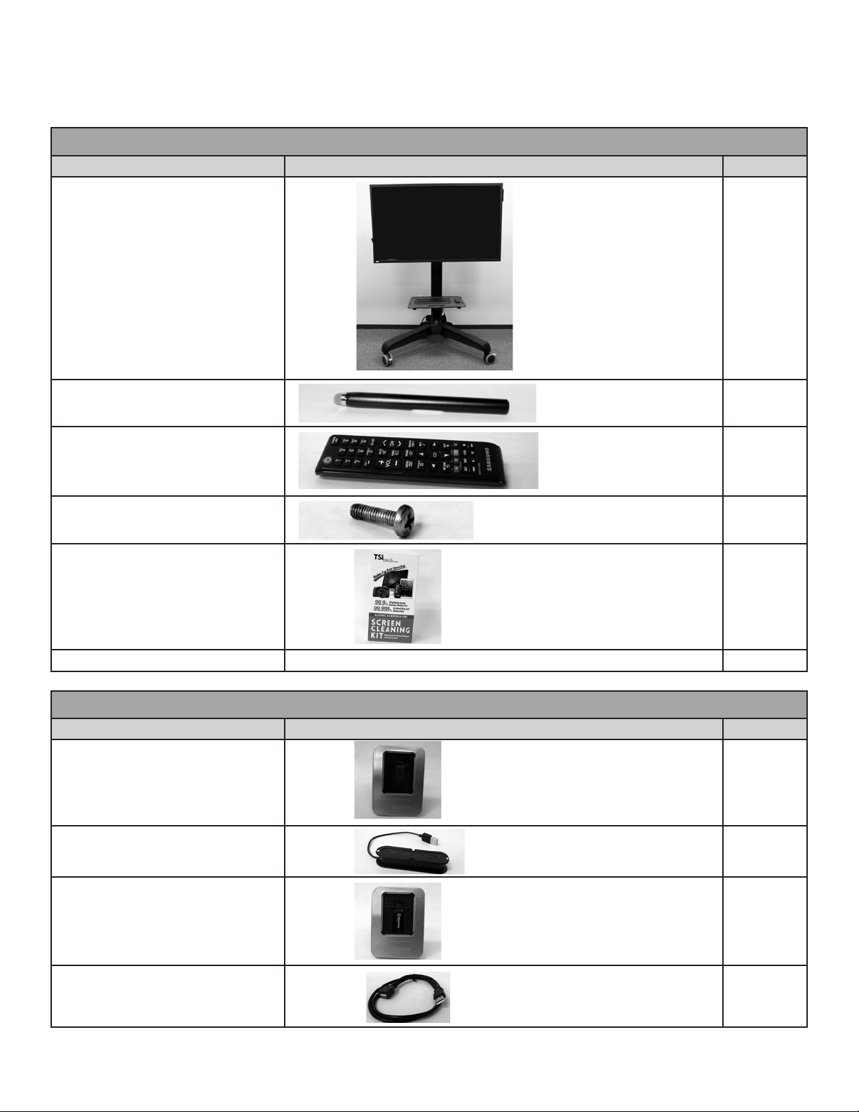
BITS Installation Component List
The components for the BITS product consists of three different kits: Hardware Kit, Software Kit, and Computer Kit. Do not
start the installation process until all three kits have been received.
BITS Hardware Kit: 117-00154-000 (55" Display) and 117-00154-001 (48" Display)
Description Illustration (Reference Only) Quantity
Touchscreen Display Monitor (with
Attached CPU Mount) Mounted on
Assembled Ergotron Display Stand
with Attached Keyboard Tray
Magnetic Stylus 2
1
Touchscreen Display Monitor
Remote Control
Mounting Plate Screws 4
Touchscreen Cleaning Kit 1
Literature
1
BITS Software Kit: 117-00152-000
Description Illustration (Reference Only) Quantity
BITS License Key
(contained in a box)
USB Hub 1
1
Encrypted Backup Drive
(contained in a box)
Extension USB Cord 1
2
1
Page 5
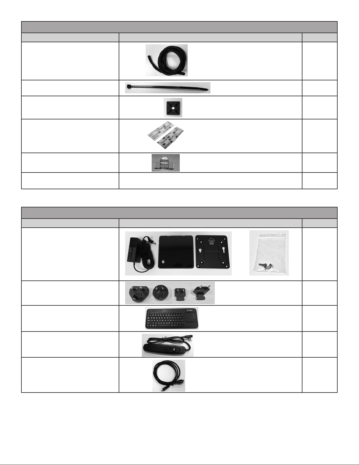
BITS Software Kit: 117-00152-000
Description Illustration (Reference Only) Quantity
Wire Loom 1
Zip Ties 10
Mounting Bases 10
Fasteners 2 packages
Round Cord Clips 1 package
BITS Installation Guide
602-00690-001
1
BITS Computer Kit: 117-00160-001
Description Illustration (Reference Only) Quantity
Computer with Mounting Bracket,
Hardware, and Power Adapter with
Cord
Multi-country AC Plugs 1
Wireless Keyboard 1
Power Strip 1
1
HDMI Cable 1
3
Page 6
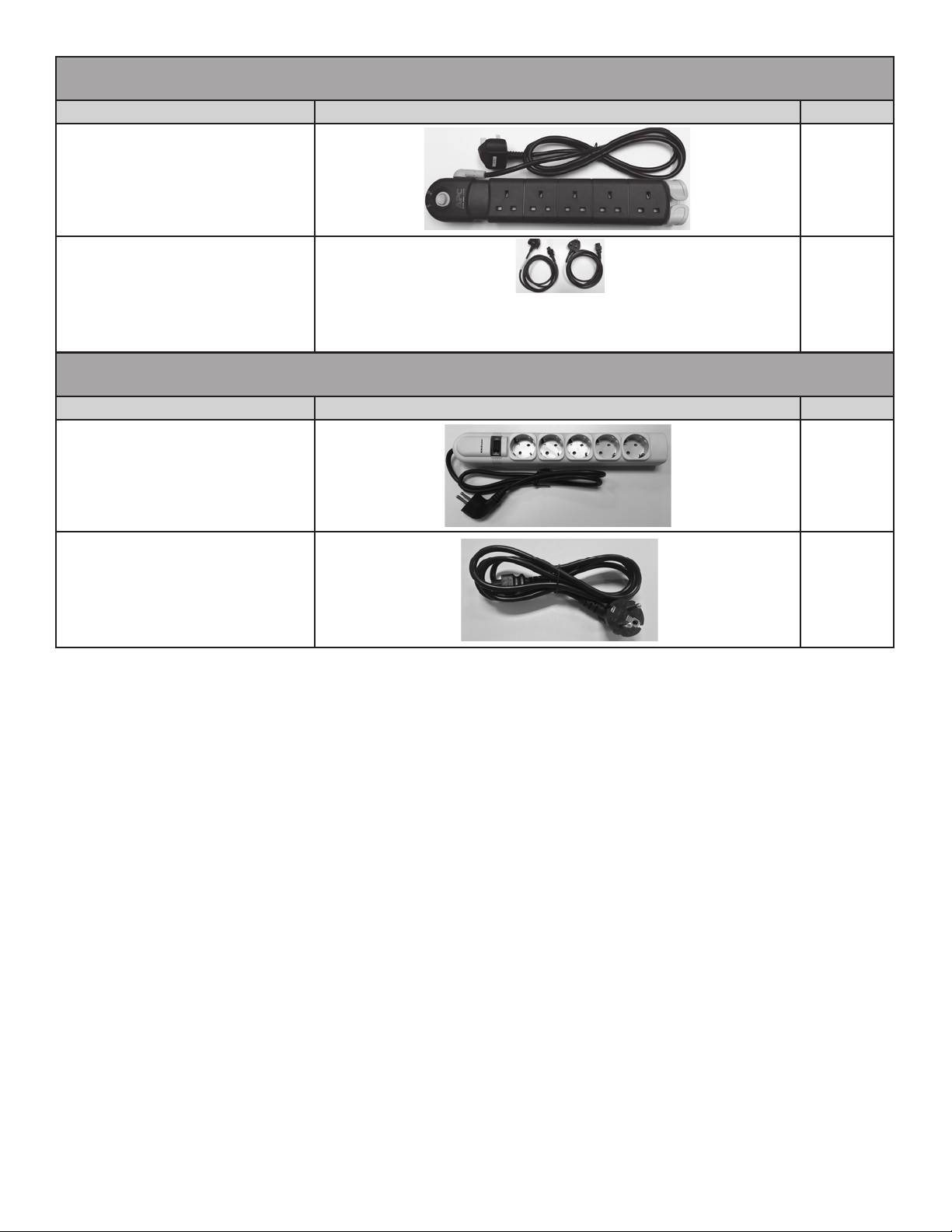
BITS Power Supply Kit (UK): BIT-A001
(Only Included with UK Installations)
Description Illustration (Reference Only) Quantity
UK Power Strip 1
UK Power Cord 1
BITS Power Supply Kit (UK): BIT-A001
(Only Included with UK Installations)
Description Illustration (Reference Only) Quantity
EU Power Strip 1
EU Power Cord 1
Note: Verify that all components have been received. Do not start the installation process if any of the listed
components are missing. For technical support contact Bioness Client Relations Department at (800) 211-9136,
Option 3 or your Bioness Sales Representative.
Tools Needed for Installation
The list below includes items needed to install the BITS. The tools are not provided with the system.
• 14mm Wrench
• 14mm Socket Driver (optional)
• Phillips Screw Driver
• Scissors
• Safety Gloves
• Box Cutter with Safety Guard
Unpacking and Setting Up the Hardware Kit
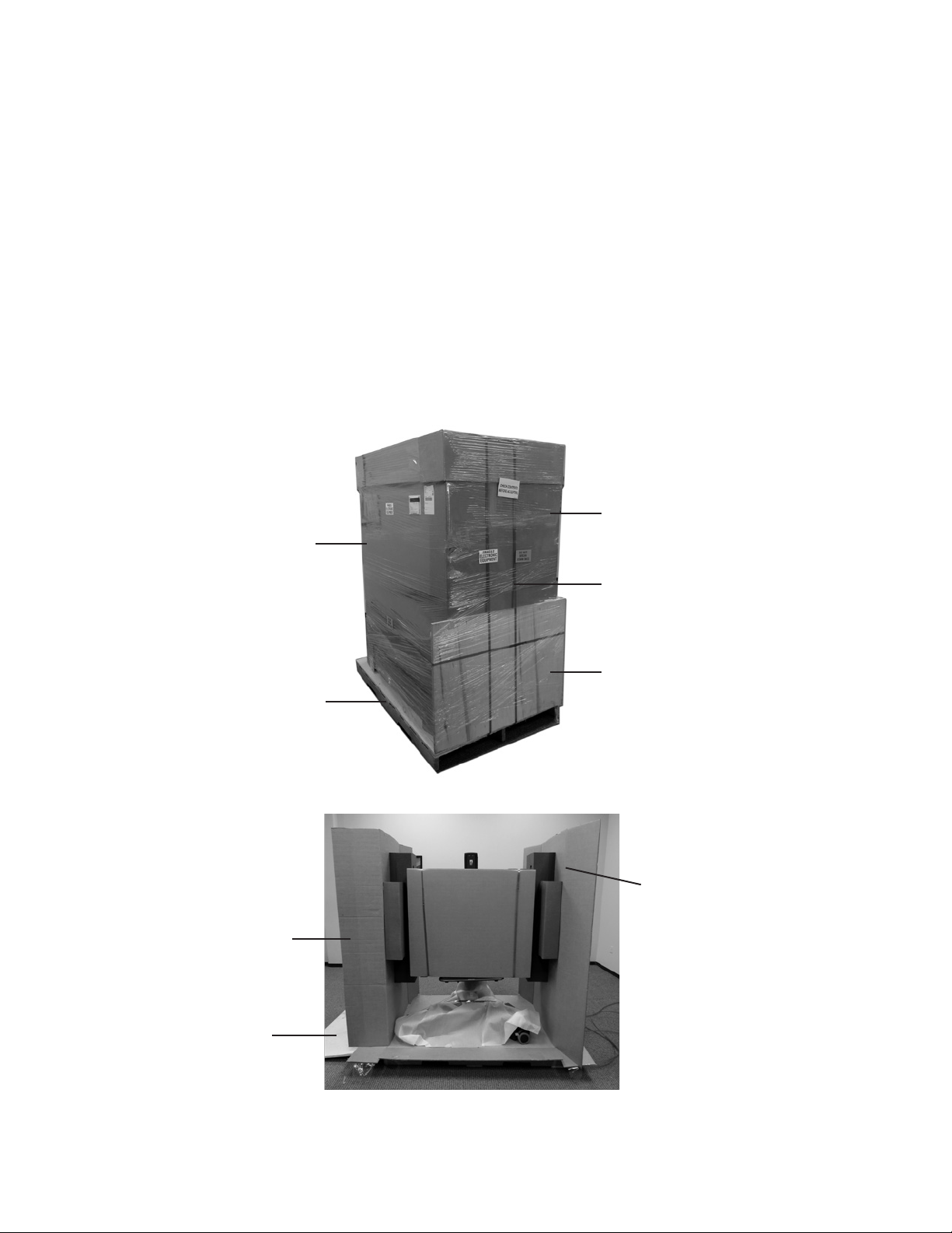
1. The BITS Hardware Kit is a large package that is delivered on top of a wooden palette. The package consists of a
palette with ramp, layered cardboard, foam inserts, shipping straps, and plastic shipping wrap. See Figure 1.
2. Remove all plastic shipping wrap by cutting it from the top with a box cutter.
3. Cut all green shipping straps. Start with the straps located above the wooden ramp, see Figure 1.
4. Lower the wooden palette ramp.
4
Page 7
5. Cut the tape around the box lid and lift to remove the lid.
6. On the bottom box lip, cut the tape and completely unfold the bottom lip on all four sides.
7. Cut the outer layer of cardboard down the middle to remove.
8. Open the side cardboard flaps and remove the front and back cardboard panels. See Figure 2.
9. Carefully remove the side cardboard panels with attached foam inserts that are supporting the Touchscreen Display
Monitor. See Figure 2.
10. Cut the green shipping straps that are attached to the anchors on the bottom of the box.
11. Remove the foam wrap and the foam blocks that are located under the BITS display stand.
12. Carefully roll the BITS System down the wooden ramp.
13. Cut the green shipping straps from the cardboard in front of the Touchscreen Display Monitor. Remove the cardboard,
foam blocks, and foam cover from the Touchscreen Display Monitor.
14. The box attached to the back of the system will contain the display screen remote control, stylus, Touchscreen
Cleaning Kit, display screen literature, and a small bag of screws. Remove the contents and set aside.
15. The Touchscreen Display Monitor was intentionally left loose to allow for rotation. Position the monitor so that it is
level, and hand tighten the knob found in the back of the mounting bracket by turning it clockwise. See Figure 3.
Card Board Box
Wooden Palette
Side Cardboard Flap
Plastic Shipping Wrap
Shipping Straps
Wooden Ramp
Figure 1: Hardware Kit Packaging
Side Cardboard
Panel with Foam Inserts
Wooden Ramp
Figure 2: Side Cardboard Flaps and Front Panel
5
Page 8
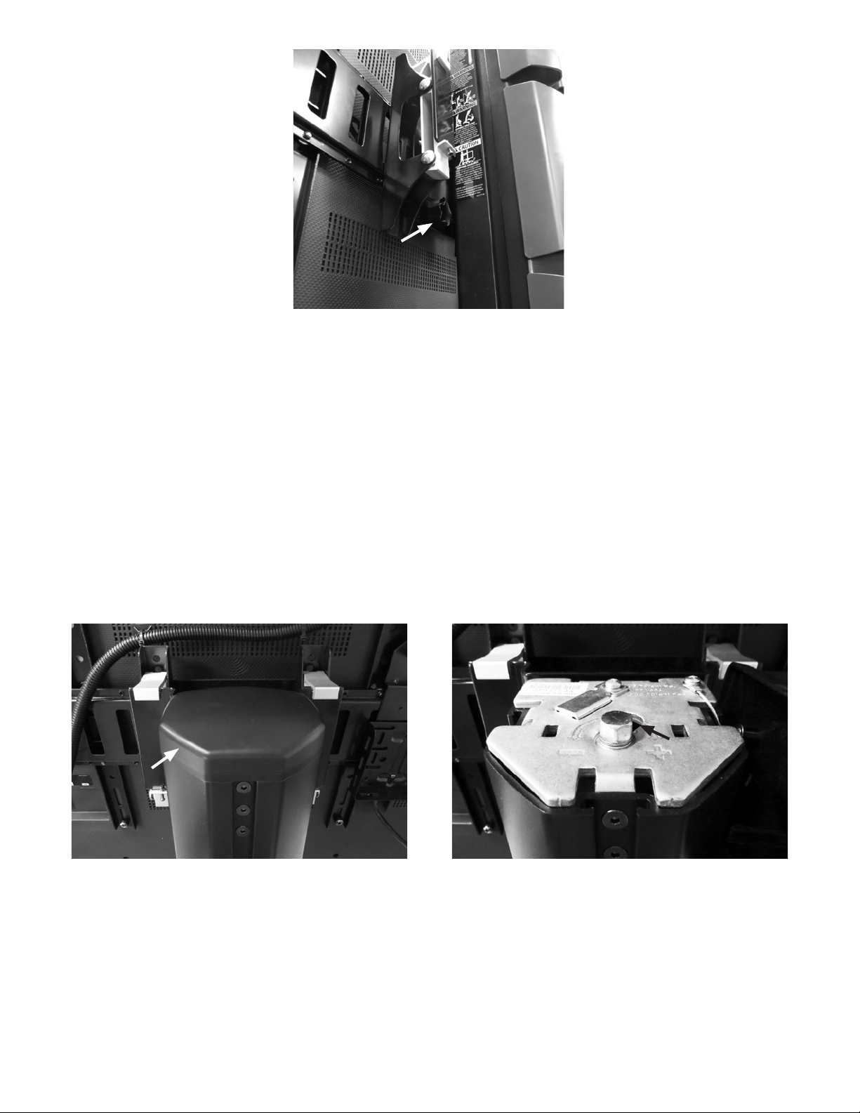
Figure 3: Knob, Back of Mounting Bracket
Adjusting Display Stand Lift Tension
The display monitor should be able to move smoothly and easily on the tower of the portable display stand and stay in place.
If movement is difficult or the display monitor does not stay in the desired position, then adjustment to the tension in the tower
is needed. Depending on the display monitor and the adjustment it may take several turns to notice a difference in tension.
To adjust the display stand tower tension:
1. Make sure the touchscreen display monitor has been moved to the highest position on the stand tower.
2. Remove the cover on the top of the portable stand tower. See Figure 4.
3. To tighten the tension, use a 14 mm wrench to turn the nut clockwise (turn toward the plus symbol). See Figure 4.
4. To loosen the tension, use a 14 mm wrench to turn the nut counter-clockwise (turn toward the minus symbol). See
Figure 4 .
5. Put the cover back on the portable stand tower.
Figure 4: Portable Stand Tower Cover (Left), Adjustment Nut on Portable Stand Tower (Right)
Computer Installation
1. Open the computer package and verify that the computer, mounting bracket, hardware, and power adapter
are present.
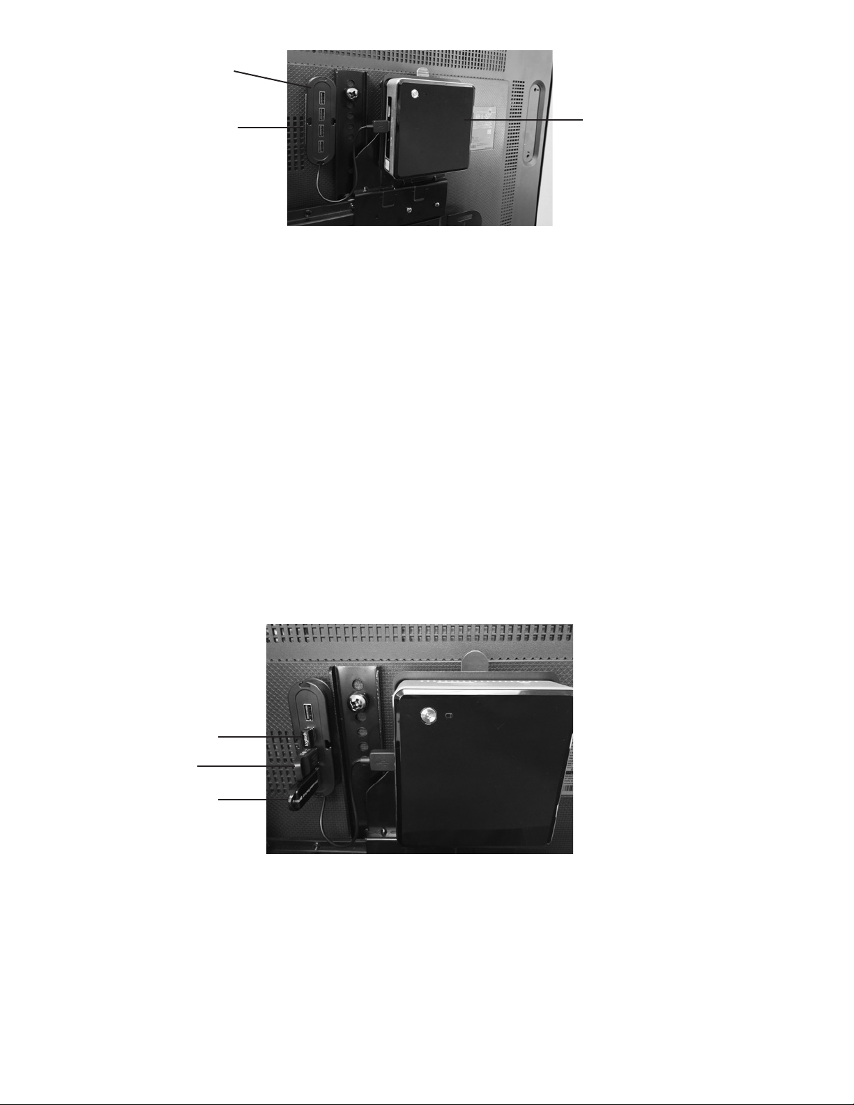
2. Attach the computer mounting bracket to the CPU Mount. See Figure 5. Secure with the four screws provided in the
Hardware Kit. The screws are located in a small bag in the box containing the remote control, Touchscreen Cleaning
Kit, stylus, and literature.
6
Page 9
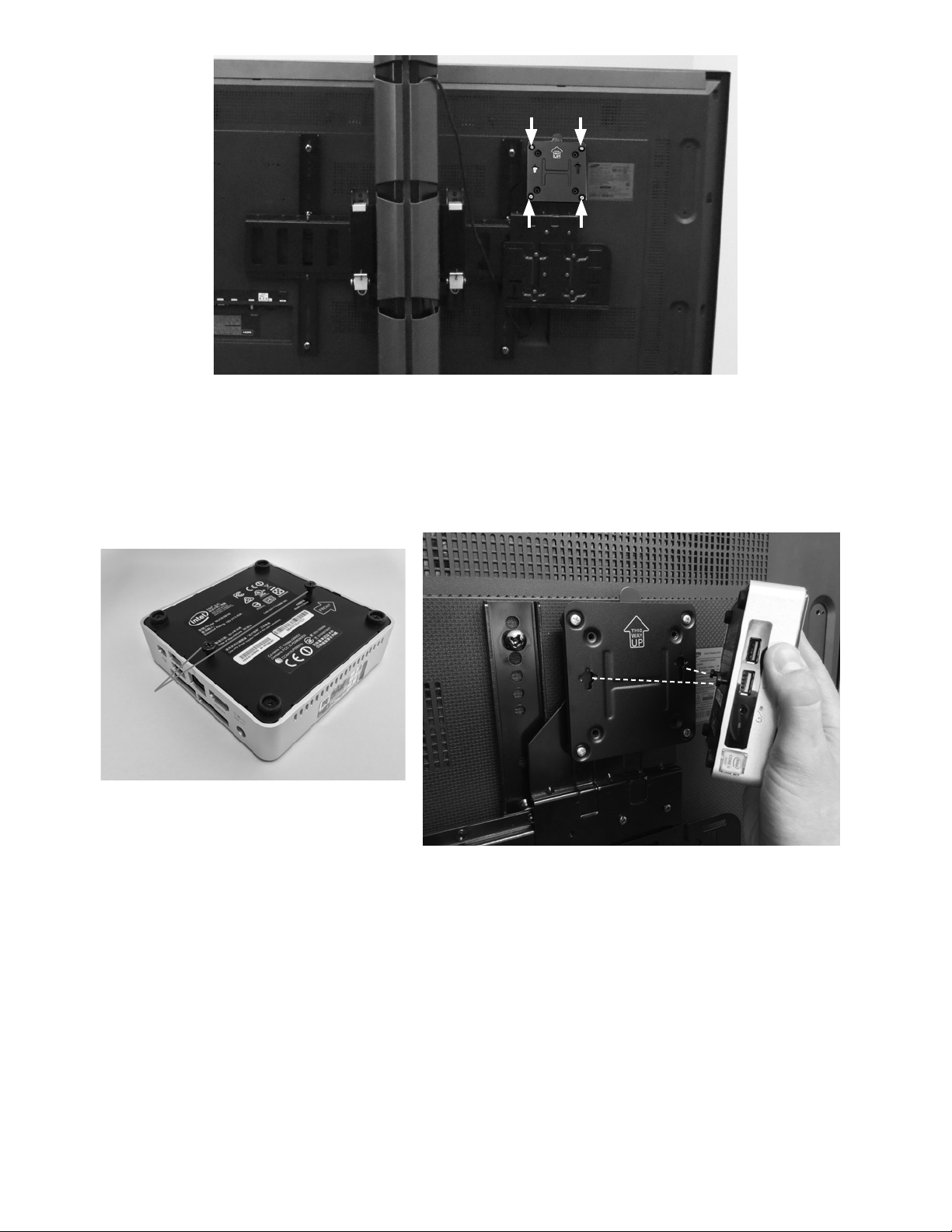
Figure 5: Attaching Computer Mounting Bracket
3. Remove the computer from the plastic bag and attach 2 screws (provided with the computer) to the back of the
computer. See Figure 6. Do not over tighten the screws. The screws will be used to slide the computer into the
computer mounting bracket.
4. Slide the computer, with attached screws, into the computer mounting bracket. See Figure 6. The computer should fit
snuggly into place and should be able to be easily removed.
Screws
Figure 6: Attaching Screws to Back of the Computer (Left)
Attaching Computer to the Computer Mounting Bracket (Right)
Note: When attached, the connection ports on the computer will be on the right hand side.
USB Hub
1. Remove the USB Hub from its packaging.
2. Connect 2 strips of fastener together. Remove the protective cover from one side and affix it to the bottom of the USB Hub.
3. Plug the USB Hub into the yellow USB port on the left side of the computer.
4. Remove the protective cover from the fastener and affix the USB Hub directly to the back of the Touchscreen Display
positioned to the left of the mounting bracket. See Figure 7.
7
Page 10
USB Hub
Small Keyboard USB
BITS License Key
Encrypted Backup USB
Fastener
Figure 7: Securing the USB Hub
Computer
BITS License Key
1. Remove the BITS License Key from the box located in the Software Kit package.
2. Remove the protective cover from the BITS License Key.
3. Plug the BITS License Key into the USB Hub. See Figure 8.
Encrypted Backup USB
1. Remove the Encrypted Backup USB from the box located in the Software Kit package.
2. Remove the protective cover from the Encrypted Backup USB.
3. Plug the Encrypted Backup USB into the USB hub. See Figure 8.
Wireless Keyboard
1. Remove the Wireless Keyboard with integrated touch pad and small USB from package.
2. Plug the small USB into the USB Hub. See Figure 8.
3. Remove the battery protection strip(s) from the bottom of the keyboard. Turn the keyboard on by sliding the switch
located on the front panel of the keyboard to the ON position.
Figure 8: Connection Locations of BITS License Key, Encrypted Backup USB, and Small Keyboard USB
Touchscreen USB
1. Remove the tape securing the Touchscreen USB cable in the lower left corner of the Display Monitor.
2. Plug the Touchscreen USB cable directly into one of the USB ports located on the ride side of the computer.
Note: The Touchscreen USB must be plugged directly into the computer and not the USB Hub in order for the
Touchscreen to function properly.
8
Page 11
USB Extension Cable
USB Extension Cable
Mounting Base
Cord Clip
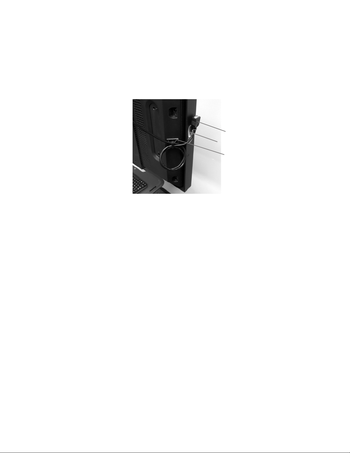
1. Remove the USB Extension Cable from its packaging.
2. Attach one of the Cord Clips to the right side of the Touchscreen bezel about six inches from the bottom of the
Touchscreen Monitor. See Figure 9.
3. Insert the USB Extension Cable into the available USB port on the right side of the computer.
4. Secure the USB Extension Cable into the Cord Clip.
5. Remove the slack from the USB Extension Cable by looping the cable with two loops, and secure the USB Extension
Cable to the Mounting Base by feeding a zip tie through the opening in the Mounting Base and tightening it around
the loops.
Figure 9: USB Extension Cable
Power and HDMI Cable Installation
1. Remove the Touchscreen Display Monitor Power Cord from package and insert into the back of the monitor.
2. Connect the PC Power Adapter to the PC Power Cord and plug it into the PC power port on the right side of the
computer.
3. Remove the HDMI cable from its packaging. Plug one end of the cable into the HDMI output on the right side of the
computer. Plug the other end into the "HDMI IN 1" input on the back of the display monitor.
Note: For Installations in the UK use the appropriate blades with the AC power adapter supplied with the computer and the
power cord supplied in the BITS Power Supply Kit, UK (BIT-A001). Discard the Touchscreen Display Monitor Power Cord
from the BITS Hardware Kit (117-00154-000 or 117-00154-001). Replace this power cord with the one supplied in the BITS
Power Supply Kit, UK (BIT-A001).
Securing the Power Strip
Note: For Installations in the UK use the Power Strip supplied in the BITS Power Supply Kit, UK (BIT-A001). Discard the
Power Strip from the BITS Computer Kit (117-00160-001) and replace it with the Power Strip supplied in the BITS Power
Supply Kit, UK (BIT-A001).
1. Connect 2 strips of fastener together. Remove the protective cover from one side and affix it to one end of the bottom
of the Power Strip.
2. Connect 2 more strips of fastener together. Remove the protective cover from one side and affix it to the other end of
the bottom of the Power Strip.
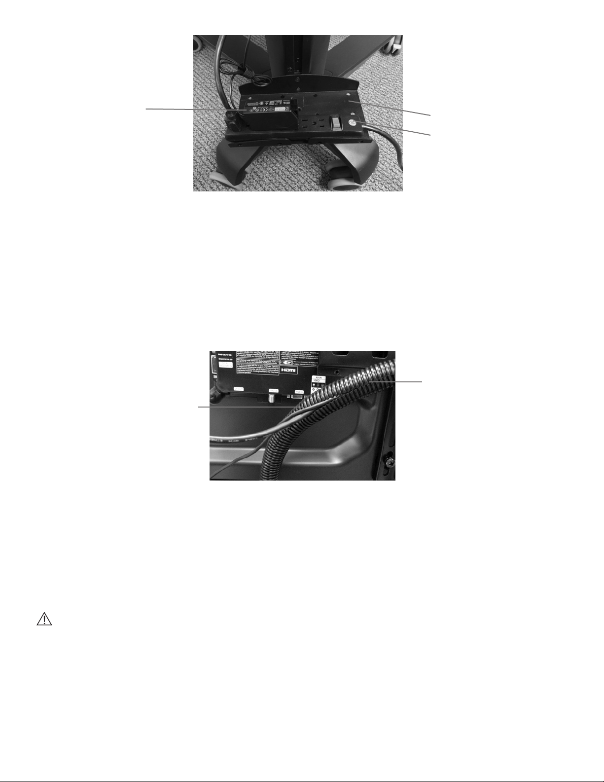
3. Remove the protective covers from the other side of both fasteners and mount the Power Strip to the Mounting
Platform on the back of the display stand. See Figure 10.
Note: Secure the power strip toward the rear of the Mounting Platform.
9
Page 12
Mounting Platform
PC Power Adapter
Power Strip
Figure 10: Mounted PC Power Adapter and Power Strip
Cable Management
The wire loom, zip ties, mounting bases, and fasteners are used for cable management.
1. Measure the length needed for the specific monitor size.
2. Remove the wire loom from packaging and cut two 4-foot long sections with scissors
Note: The length of wire loom needed will differ depending on the Monitor Display size.
3. Using one of the wire loom pieces, open the split seam on the wire loom and insert in the HDMI Cable and Touchscreen
USB Cables. See Figure 11.
Seam
Insert Cables
4. Remove the protective covers from five mounting bases and attach the bases to the back of the Display Monitor. See
Figure 12 for suggested attachment locations. The number of mounting bases used and the attachment position will
vary depending on the Display Monitor size.
5. Feed the zip ties through the openings in the mounting bases. See Figure 13.
6. Secure the zip ties around the wire loom and tighten. See Figure 13. Cut off the excess zip tie material with scissors.
7. Create a loop with the HDMI cable, and secure it to the mounting base and tighten. Cut off the excess zip tie material
with scissors
Caution: Be careful when cutting the zip tie material near electrical cables.
8. With the second piece of wire loom, open the split seam on the wire loom and insert in the PC Power Cord and
Touchscreen Display Monitor Power Cord. See Figure 14.
10
Figure 11: Inserting Cables into the Wire Loom
Page 13
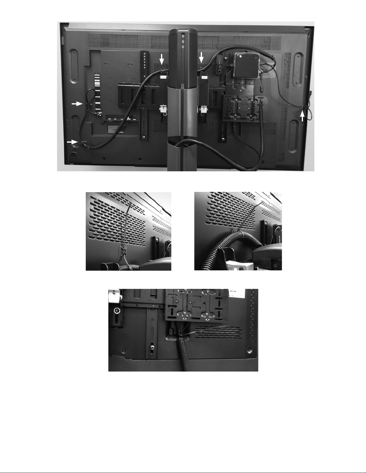
Figure 12: Mounting Bases Attachment Locations for 55" Monitor (example only)
Figure 13: Feeding Zip Tie into Mounting Base (Left), Securing Zip Tie (Right)
Figure 14: Inserting PC Power Cord and Display Monitor Cord (example only)
9. Carefully push the Touchscreen Display Monitor down to the lowest position on the tower of the display stand.
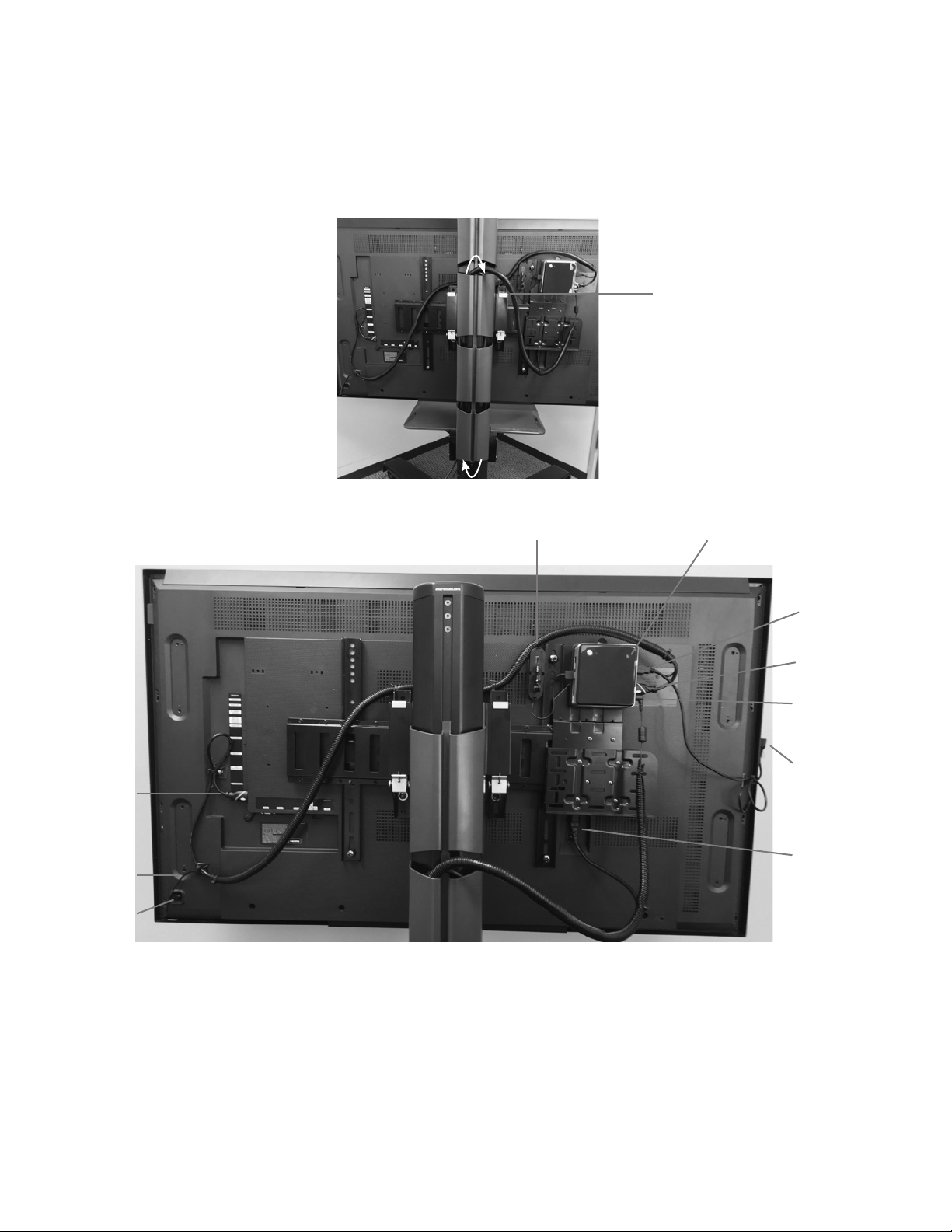
10. Insert the wire loom (with the PC power and Display Monitor cords) into the left side of the tower covers that are
located on the back of the display stand. Start with the cover that is second to the top. Make sure to include enough
slack in the wire loom to accommodate the movement of the display stand. See Figure 15. This is needed so the
cables do not pull out of their connection points when the Display Monitor is in the highest position on the display stand.
11. Wind the Touchscreen Display Monitor Power Cord up the right side of the display stand tower covers and back down
the left side.
11
Page 14
12. Plug the PC power cord and Display Monitor power cord into the power strip. Set the power switch on the Power Strip
HDMI Cable
USB Hub
Computer
to the ON position.
13. Raise and lower the position of the Display Monitor on the display stand to verify that the wire loom with cables can
move freely with the monitor. If the cables cannot move freely, then adjust the length of wire loom that was inserted
into the tower covers.
14. Wind the excess cable length of the PC power cord, and wrap it with the attached cable strap.
Note: Final cable management assembly may differ depending on Display Monitor size.
Slack in Wire Loom
Figure 15: Wire Loom Inserted into Left Side of the Tower Covers
Touch Screen
USB
PC Power
Adapter and
Power Cable
USB Extension
Port
HDMI Cable
Display Monitor
Touchscreen
USB Cable
Touchscreen
Panel Key
Power Cable
Figure 16: Example of BITS with Completed Cable Management
Moving the BITS Display Stand
After the BITS hardware has been installed, the system will need to be moved to the location designated for therapy sessions.
To move the portable display stand:
1. Carefully push the touchscreen display monitor down to the lowest position on the tower of the portable display stand.
See Figure 17.
12
Page 15
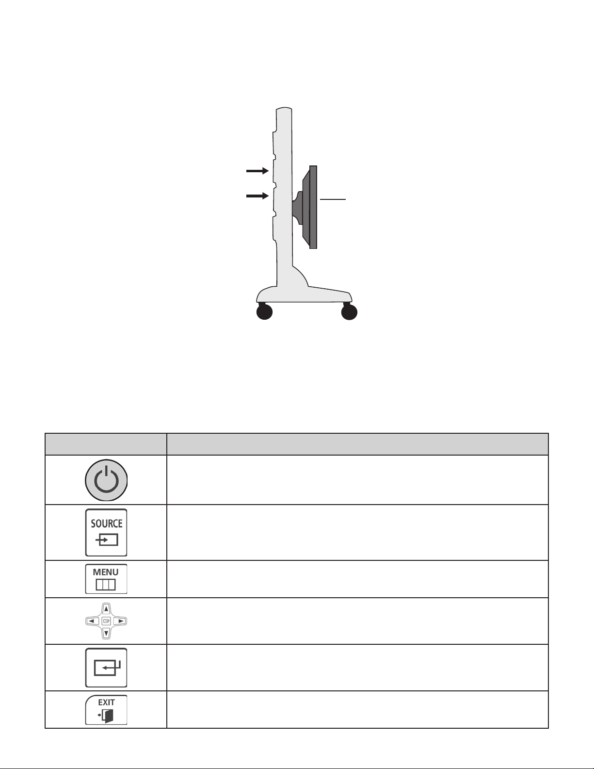
2. Unlock the wheel casters and point the wheels in the direction of travel.
3. Push the portable display stand from the side with both hands on the tower. See Figure 17.
4. Move the display stand to the new location and lock the wheel casters.
5. Position the Display Monitor to the desired height by pushing the bottom of the screen vertically with two hands.
Position of Hands
on Tower
Position of Touch
Screen Display
Figure 17: Correct Position for Moving Portable Display Stand
6. Plug the power cord on the Power Strip into a 3 pronged grounded wall outlet.
Samsung Display Monitor
The Display Monitor requires the use of a Remote Control. See Table 1 below for descriptions of the commonly used buttons
on the Remote Control.
Icon Description
Power On: Press the Power On button to turn on the Display.
Source: Press the source button to select the correct HDMI input.
Menu: Press the Menu button to open the Display settings.
Navigation: Use the Up, Down, Left and Right arrow buttons to
navigate through the available options.
Enter: Press the Enter button to make selections and confirm
setting changes.
Exit: Press the Exit button to close the Display settings.
13
Page 16
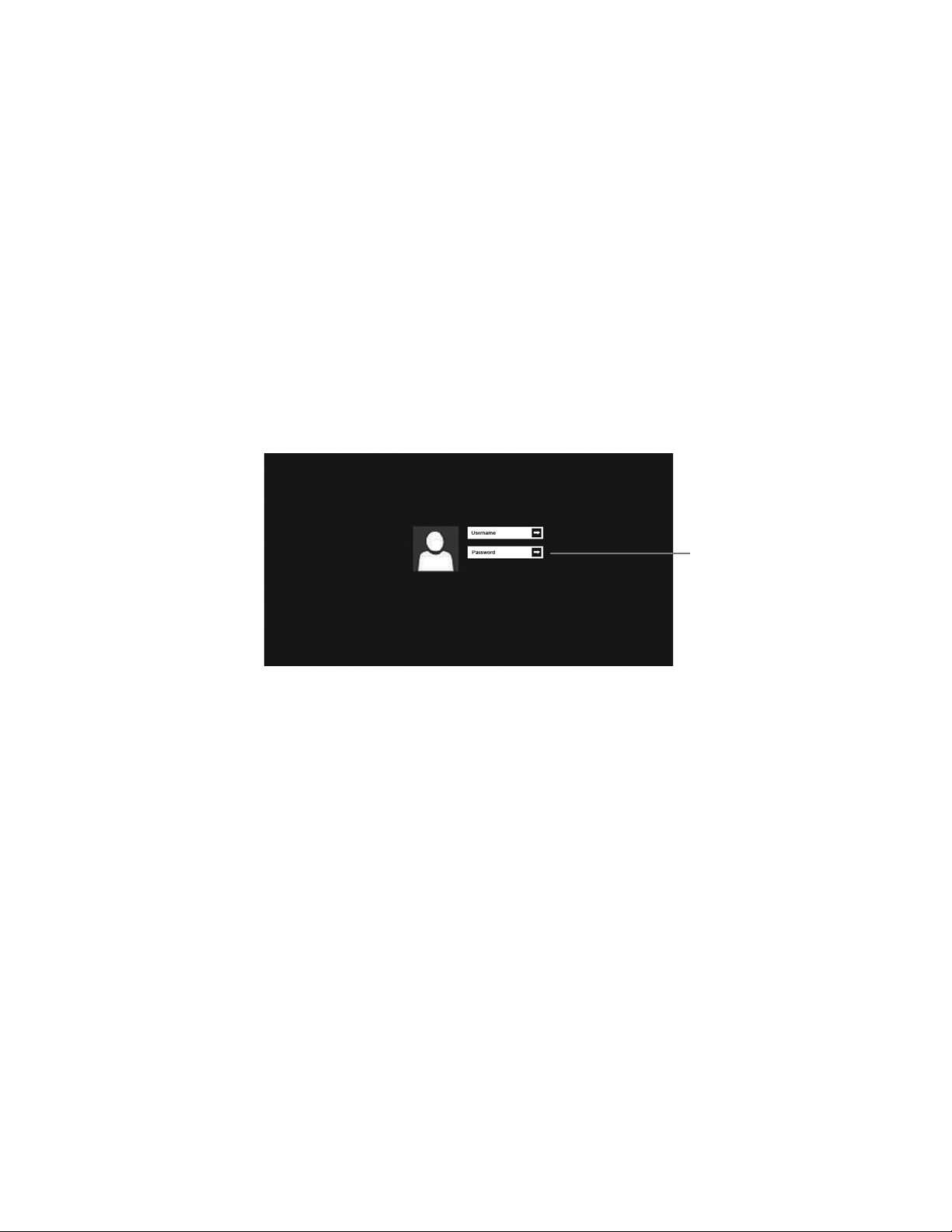
Table 1: Remote Control Buttons
Input Source
After plugging the Power Cord into the wall outlet, press the Power On button to turn on the Display Monitor.
1. Press the Source button on the Remote Control.
2. Use the Left and Right arrow buttons to navigate to HDMI 1 or HDMI 2.
3. Press the Enter button to confirm the setting.
Turning the System On
1. Press the On/Off button on the center of the bottom edge of the Display Monitor.
2. Press the On/Off button on the computer.
Note: The touchscreen display will enter a sleep mode and shut down when the computer is inactive. While in this sleep
mode, turning on the computer will also activate the touchscreen display.
3. Once the Display Monitor has turned on, touch the middle of the touchscreen and slide up to reveal the Windows
Login Screen. See Figure 18.
4. Use the wireless keyboard or the on-screen keyboard to enter in "BITS" as the username and "bits" as the password.
Enter Arrow Button
Press the Enter Arrow Button. See Figure 18.
Figure 18: Windows Login Screen
Picture Settings
Users may need to adjust the Backlight, Brightness, Contrast or Sharpness of the display to accommodate patients with
sensitive vision. Follow the instructions below to adjust the picture settings using the remote control. See Table 1 for
descriptions of the buttons on the remote control.
1. Press the Menu button.
2. Press the Enter button to select Picture settings.
3. Use the Up and Down buttons to navigate to the Backlight, Brightness, Contrast or Sharpness setting, and press the
Enter button to select it.
4. Use the Left and Right buttons to increase or decrease the selected setting.
5. Press Enter to confirm the setting changes.
6. Press Exit to close the display Menu.
Calibrating the Touch Screen Display
1. Access the Windows 8 Start Screen by pressing the Start button in the lower-left corner of the screen.
2. Click on the tile for the folder called, “PulseIRUtility_1.0.1.8_”
14
Page 17
3. A File Explorer window will open. Open the file called, “Pulse IRController.exe”
4. The User Account Control pop up window will display. Press the "Yes" Button to proceed.
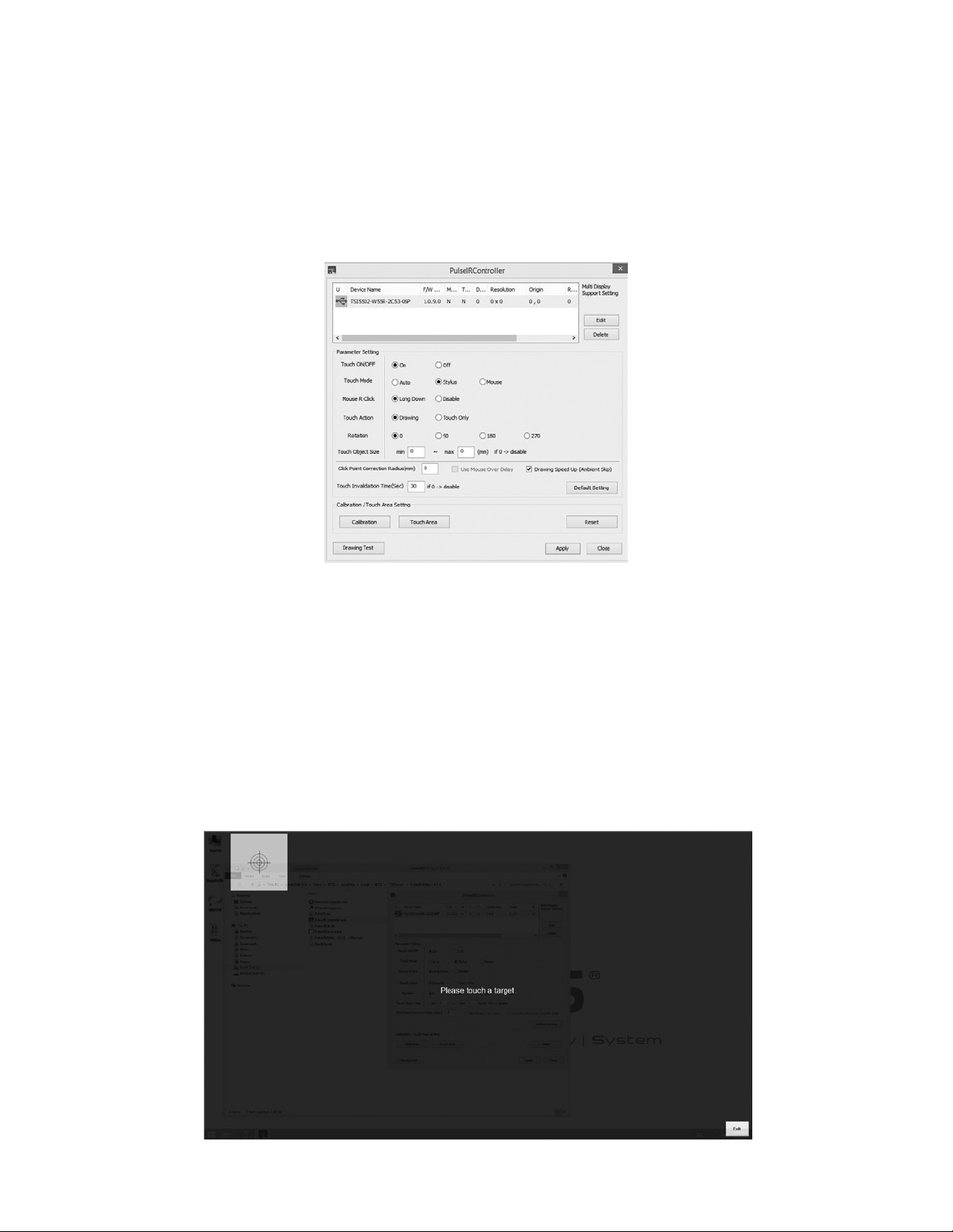
5. The PulseIRController window will appear. Touch the Reset Button.
6. Confirm that the Parameter Settings shown on the PulselRController window are the following:
• Touch ON/OFF: On
• Touch Mode: Stylus
• Mouse R-Click: Long Down
• Touch Action: Drawing
• Rotation: 0
7. Once the settings have been confirmed, touch the Apply Button. See Figure 19.
Figure 19: PulseIRController Window
8. A pop up window will appear stating, "Complete!" Touch the OK Button.
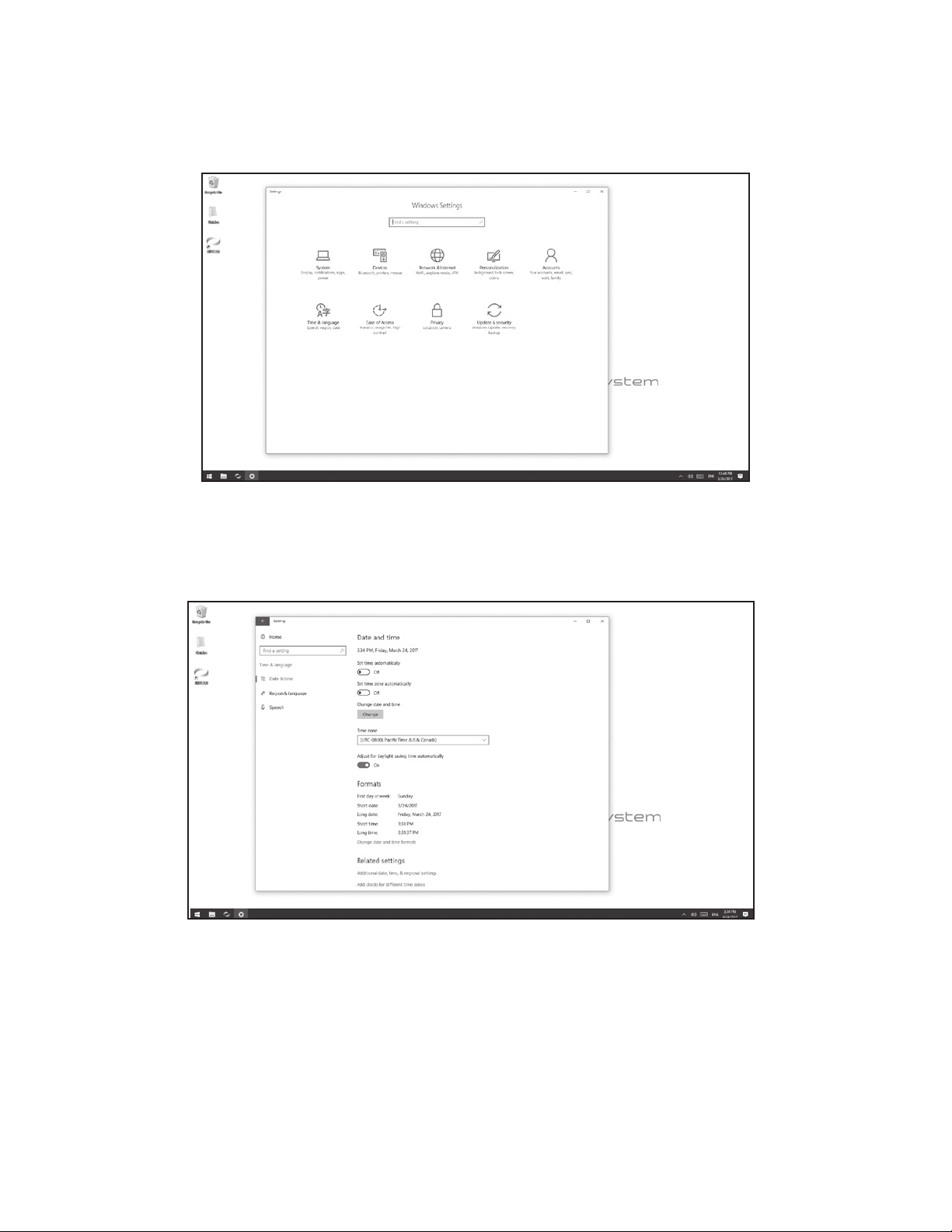
9. To calibrate the touch area, press the Calibration Button on the PulseIRController Window. See Figure 19. The
calibration screen will display. See Figure 20.
10. Position your body in the center of the Display Monitor and press the center of each consecutive target. Targets will
appear in the top left, top right, and bottom left corners of the touchscreen. Once all targets have been accurately
touched, the user will need to press the OK Button.
11. The display screen will go back to the PulseIRController Window. Touch the Apply Button.
12. A pop up window will appear stating, "Complete!" Touch the OK Button.
13. To verify that the calibration was completed accurately, drag the tip of a finger across the desktop and confirm that the
15
Page 18
curser tracks with finger movement.
Figure 20: Calibration Screen
Date and Time Settings
The computer date, time, and time zone settings will need to be verified.
1. From the Windows Settings menu, select the Time & Language settings icon. See Figure 21
Figure 21: Windows Settings Menu
2. Select the appropriate time zone from the drop down menu. See Figure 22.
3. Verify that the time and date is correct, and press the Change Date and Time Button to adjust the date and time
manually if needed.
Figure 22: Date and Time Settings Menu
Printer Setup
Only USB connected printers should be connected to the BITS PC.
1. Follow the setup instructions specific to the printer being attached to the BITS PC.
2. Upload the necessary printer drivers onto a USB memory device
16
Page 19
3. Connect the USB printer cable to the empty USB port on the USB hub.
4. Insert the USB memory device into the USB Extension Cable, and install the necessary printer drivers onto the BITS
Computer.
Note: Connecting the BITS PC to the Internet will void the warranty.
Testing the BITS Software
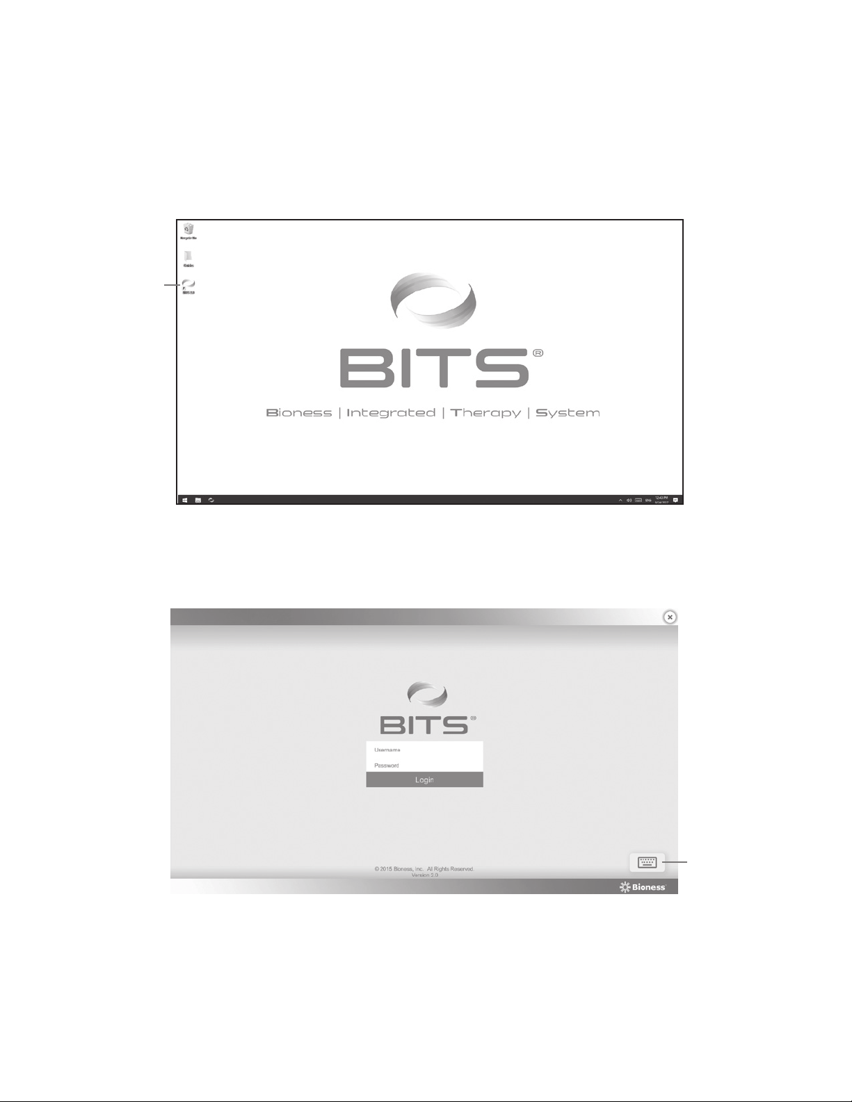
You will need to log into BITS software application to confirm that it is running.
BITS
Icon
1. Press the BITS Icon located on the desktop. See Figure 23.
Figure 23: BITS Icon on Desktop
Keyboard
Icon
2. The BITS Login Screen will open. To open the on-screen keyboard, press the Keyboard Icon located at the bottom
right of the screen. See Figure 24.
Figure 24: BITS Login Screen
3. Use the keyboard to enter "admin" as the username and "BITS" as the password.
4. Press the Login Button to complete the login process.
17
Page 20
X Button
System
Settings
Button
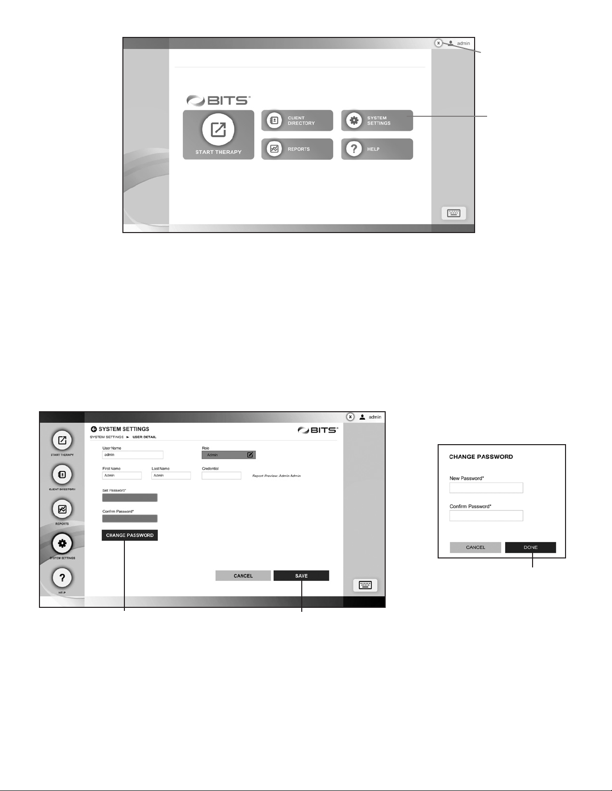
5. The Home Screen will open. See Figure 25.
Figure 25: Home Screen
Changing the Administrator Profile Password
For security purposes, it is recommended that the default Administrator Profile Password be changed before adding Client
Profiles or entering patient data into the BITS System.
1. From the Home Screen, press the System Settings Button. See Figure 25.
2. From the System Settings Screen, select the admin account from the User List by pressing the row.
3. The User Detail Screen will open. See Figure 26.
4. Enter a new User Name, First Name, Last Name, and Clinical Credentials into the text fields.
Save ButtonChange Password Button
Done Button
5. Press the Change Password Button. See Figure 26.
Figure 26: User Detail Screen (Left), Change Password Pop Up Window (Right)
6. The Change Password pop up window will open. Enter a new password, confirm the password, and Press the Done
Button. Figure 26.
7. Give the revised password to the administrator.
18
Page 21
Global Language
Preference Field
Date, Time &
Number Format
Preference Field
Changing the Language Preference Settings
The default language setting for BITS is English (US).
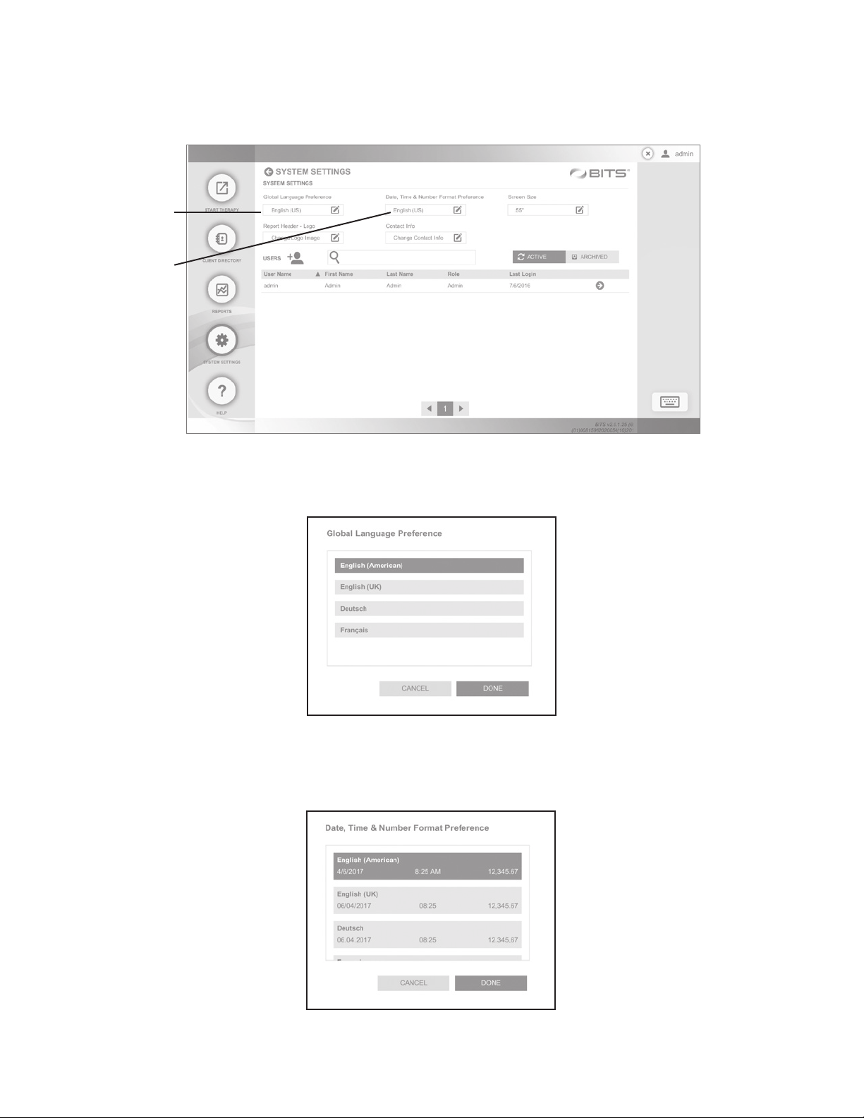
1. Navigate to the System Settings Screen.
2. Click on the Global Language Preference field. See Figure 27.
Figure 27: Change the Language Settings from the System Settings Screen
3. Select the desired language, and press the Done Button. See Figure 28.
4. Click on the Date, Time & Number Format Preference field. See Figure 27.
5. Select the desired language and press the Done Button. See Figure 29.
Figure 28: Select the Desired Language
19
Page 22
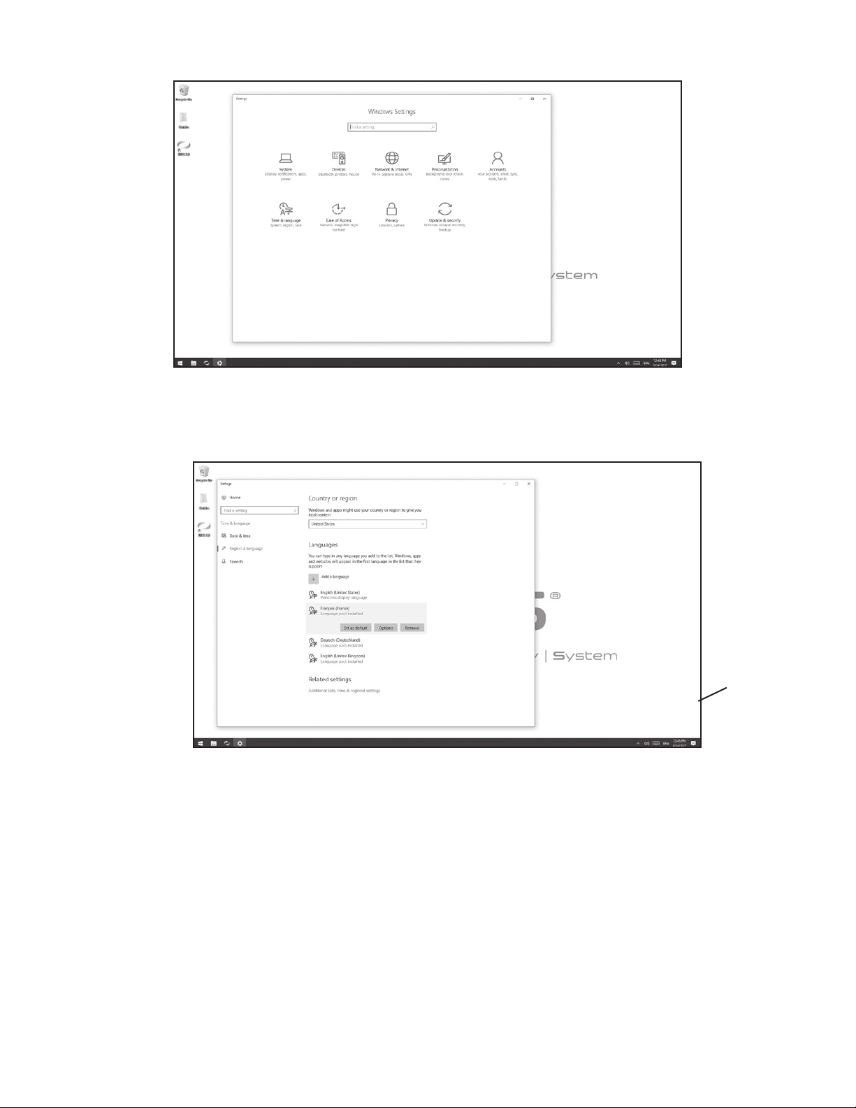
Figure 29: Select the Desired Language for Date & Time Format
6. From the Windows Settings menu, select the Time & Language settings icon. See Figure 30.
Figure 30: Windows Settings Menu
7. From the Region & Language menu, select the appropriate language and press Set as default. See Figure 31.
8. Restart Windows for the change to the Windows Display Language to take effect.
Language Selection
Figure 31: Region & Language Settings Menu
Log Out and Exit
To log out of the BITS software application, press the "X" Button. The "X" Button is located in the upper right corner of the
display screen in the BITS software, see Figure 26. Pressing the Logout Button will bring the user back to the Login Screen.
To exit the BITS software application, press the "X" Button located in the upper right corner of the Login Screen. The display
screen will return to the operating system's desktop.
The installation process for the Bioness Integrated Therapy System is now complete.
20
Page 23
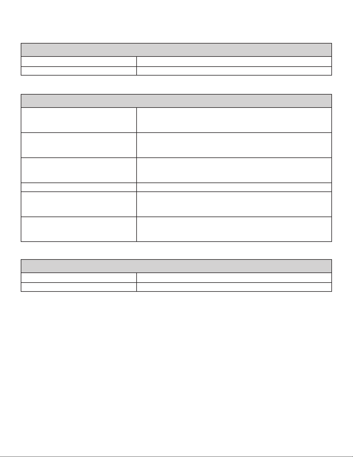
Technical Specifications
BITS Hardware Kit Specifications
Shipping Dimensions (approximately) 54" length, 73.5" height, 39.75" depth
Shipping Weight (approximately) 257 lbs
Touchscreen Display Monitor Specifications
• 48" Screen
Monitor Options
Dimensions (approximately)
Weight (approximately)
Resolution 1920 x 1080
Power Consumption
Environmental Ranges
• 55" Screen
• 65" Screen (Note: no longer commercially available.)
• 26" height, 44" width, 3" depth (48 inch option)
• 30" height, 50" width, 2" depth (55 inch option)
• 37" height, 61" width, 4.75" depth (65 inch option)
• 50 lbs (48 inch option)
• 65 lbs (55 inch option)
• 115 lbs (65 inch option)
• 97W / 121W (48 inch option)
• 122W / 143W (55 inch option)
• 122W (65 inch option)
Operating Temperature Range: 32°F to 104°F
Transport and Storage Temperature Range : -40°F to 176°F
Relative Humidity range: 10% to 80%
Portable Stand Specifications
Shipping Dimensions (approximately) 66" length, 20" height, 14" depth
Shipping Weight (approximately) 101 lbs
The system consists of mechanical and electronic components. Inadequate handling of those components may cause health
hazards. Disposal of the system must comply with local regulations.
21
Page 24

Page 25
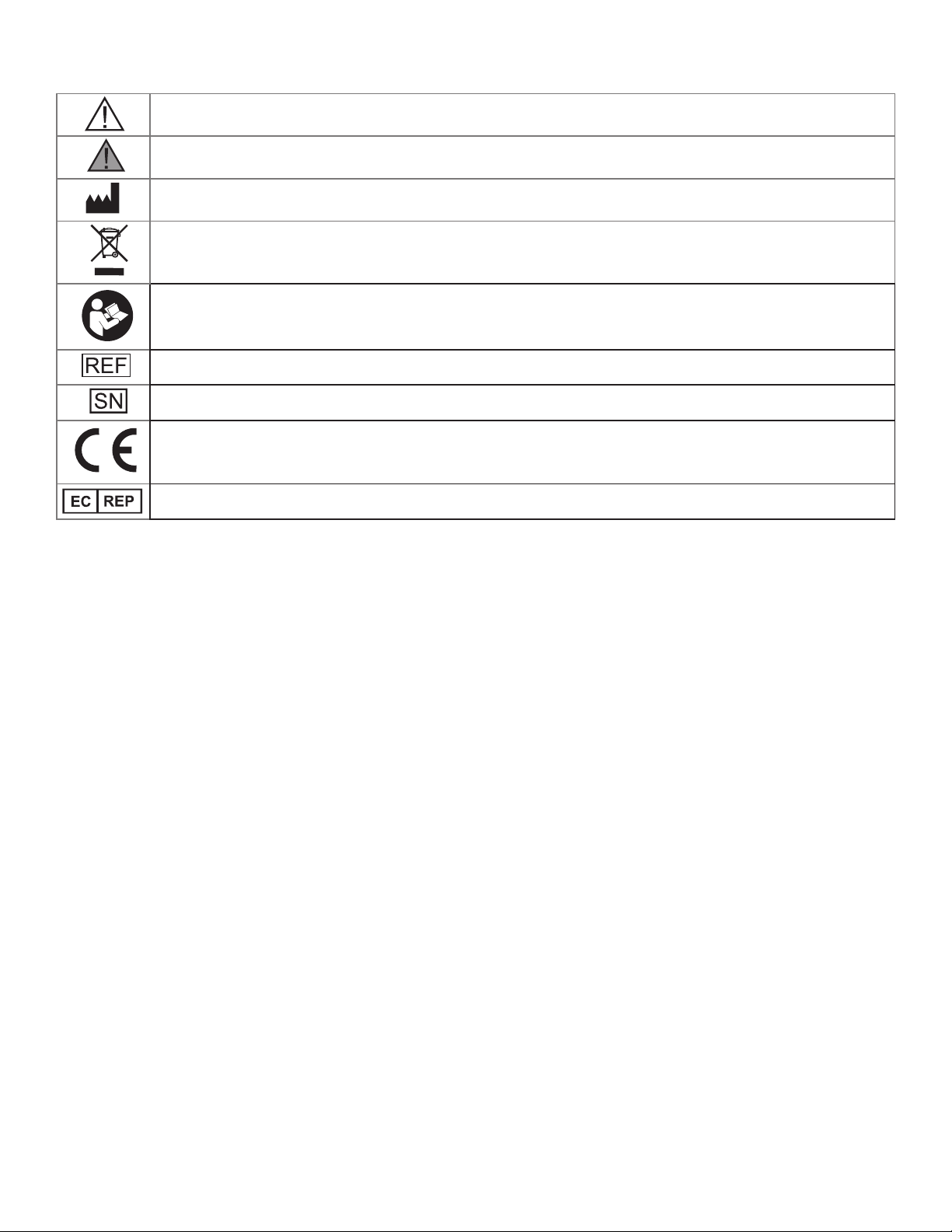
List of Symbols
Caution
Warning
Manufacturer
This Product Must Not Be Disposed of with Other Household Waste
Refer to instruction manual/ booklet
Re-Order Number
Serial Number
Complies with the European Union Medical Device Directive
European Authorized Representative
23
Page 26
Bioness Inc.
25103 Rye Canyon Loop
Valencia, CA 91355
Telephone: 800.211.9136 or 661.362.4850
Email: [email protected]
Website: www.bioness.com
Bioness Europe B.V.
Stationsweg 41
3331 LR Zwijndrecht, The Netherlands
Telephone: +31.78.625.6088
Email: [email protected]
Website: www.bioness.com
Rx Only
BITS®, Bioness, the Bioness Logo® and LiveOn® are registered trademarks of Bioness Inc. in the United States or other countries |
www.bioness.com
©2019 Bioness Inc.
All Rights Reserved
No part of this publication may be reproduced, transmitted, transcribed, stored in a retrieval system, or translated into any language or
any computer language, in any form or by any third party, without the prior written permission of Bioness Inc.
Disclaimer
Bioness Inc. and its affliates shall not be liable for any injury or damage suffered by any person, either directly or indirectly, as a result of
the unauthorized use or repair of Bioness Inc. products. Bioness Inc. and its affiliates do not accept any responsibility for any damage
caused to its products, either directly or indirectly, as a result of use and/or repair by unauthorized personnel.
Environmental Policy
Service personnel are advised that when changing any part of the BITS System, care should be taken to dispose of those parts
in the correct manner; where applicable, parts should be recycled. When the life cycle of the BITS System has been completed,
the product should be discarded according to the laws and regulations of the local authority. For more detailed information
regarding these recommended procedures, please contact Bioness Inc. Bioness Inc is committed to continuously seeking
and implementing the best possible manufacturing procedures and servicing routines.
602-00690-001 Rev. G
08/2019
 Loading...