

Page 1
100 Interpace Parkway • Parsippany, NJ 07054
800.526.2579 • www.biomet.com • 1068012L Rev B
©2010 EBI, LLC. All trademarks are the property of Biomet, Inc.or its subsidiaries
unless otherwise indicated. Velcro
®
is a registered trademark of Velcro Industries, B.V. Rx Only.
EC REP
Authorized European Representative
Biomet UK Ltd.
Waterton Industrial Estate
Bridgend
CF31 3XA UK
Page 2
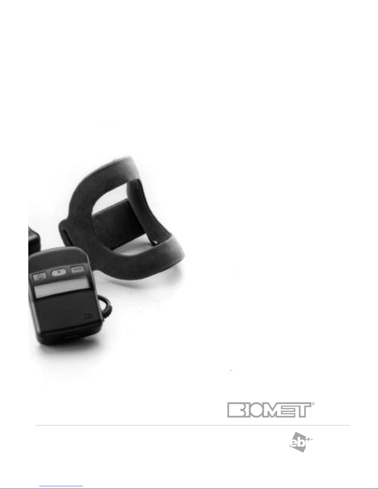
Non-Invasive Stimulation
OPTIONS • EVIDENCE • EXPERIENCE
EBI Bone Healing System
®
Model 2001
User Manual and
Package Insert
Page 3

IMPORTANT SAFEGUARDS
READ ALL INSTRUCTIONS BEFORE USING
When using electrical products, basic safety precautions should always
be followed, including:
WARNING: To reduce the risk of electric shock, fire or potential injury:
1. Do not use while bathing.
2. Do not place or store product where it can fall or be pulled into
a tub or sink.
3. Do not immerse the control unit, coil, battery charger/power unit, or the
battery charger cradle in any liquid.
4. Do not reach for a product that has fallen into a liquid.
Unplug from the wall outlet immediately.
5. Do not permit the battery charger to be connected when wet.
6. Do not drop the control unit, coil, battery charger/power unit, or
the battery charger into any liquid.
7. Avoid touching the battery contacts when the battery charger cradle is
plugged into an outlet.
8. Do not place the battery charger cradle in the bed with you if you are
using the unit while you are sleeping.
9. Never operate this product if it has a damaged link cable, cord or plug,
if it is not working properly, if it has been dropped and damaged, or
dropped into any liquid. Return the product to EBI.
10. Keep all cords away from heated surfaces.
11. Never insert any object into any opening of the system.
12. Do not place the control unit or the battery charger in prolonged heat
or direct sunlight (Normal operating temperature range is 0°C to 38°C,
[32°F to 100°F], normal storage/transport temperature is -15°C to 45°C
[5°F to 113°F]).
13. Connect this product to a properly grounded outlet
(See GROUNDING INSTRUCTIONS).
14. Use this product only for its intended use as described in this manual.
15. Medical Electrical Equipment needs special precautions regarding
Electromagnetic Compatibility (EMC) and needs to be operated according to the
EMC information provided in this instruction manual.
NOTE: Call the Biomet Patient Support Department in New Jersey
between 8:30 a.m. and 6:30 p.m. Eastern Time at 1-973-299-9300 with
any questions or problems. Outside the United States contact your local
EBI/Biomet Distributor.
SAVE THESE INSTRUCTIONS
Contents:
Model 2001 Control Unit
FLX
®
Treatment Coil with straps (if applicable)
Connector cables
Belt and Pouch (if applicable)
Recharger base
Recharger Power Supply
User Manuals (2)
FLX
®
Gauge
Travel Card
Carrying Case
Caution: Federal Law (U.S.A.) restricts this device to sale by or on the order of a physician.
For Prescription Use Only.
Page 4

TABLE OF CONTENTS
IMPORTANT SAFEGUARDS & CONTENTS ........................................Inside Front Cover
TABLE of CONTENTS....................................................................................................1
EBI BONE HEALING SYSTEM®Stimulator....................................................................3
• Description ............................................................................................................3
• Electrical Requirements ..........................................................................................3
SYSTEM COMPONENTS ..............................................................................................4
FULL PRESCRIBING INFORMATION ............................................................................5
• Indications For Use ................................................................................................5
• Contraindications, Warnings ..................................................................................5
• Precautions, Adverse Effects ..................................................................................6
• Directions For Use ..................................................................................................6
• Fracture Healing in Response to PEMFS ................................................................7
OPERATING INSTRUCTIONS ..................................................................................8-17
• STEP 1: Battery Charging....................................................................................8-9
• STEP 2: Preparing the System to Begin Treatment ..............................................10
• STEP 3: Treating and Charging ............................................................................11
• STEP 4: Recharging the Batteries ........................................................................11
• KEYPAD FUNCTIONS ......................................................................................13-15
• TROUBLESHOOTING SYSTEM MESSAGES ....................................................15-17
FLX®FLEXIBLE TREATMENT COILS ..........................................................................18
• FLX®-1, FLX®-2, FLX®-3, FLX®-4 and FLX®-5 Coil Application, Instructions ....19-20
• Conforming the FLX®Coil ....................................................................................21
• Casted Applications ..............................................................................................22
• Noncasted Applications ........................................................................................23
• Flexion Gauges ................................................................................................24-28
FLX®1-1 OR 2-1 OR 4-1 LONG VERTICAL FRACTURE APPLICATION ......................29
• Coil Application Instructions ................................................................................29
• Flexion Gauge Instructions for FLX®1-1, FLX®2-1 & FLX®4-1 Coils ..................30
• Flexion Gauges ................................................................................................31-33
FLX®1-2, 2-2 Metatarsal Application ........................................................................34
• Coil Application Instructions ................................................................................34
• Flexion Gauge Instructions for FLX®1-2 & FLX®2-2 Coils ..................................35
• Flexion Gauges ................................................................................................36-37
FLX®1-3 OR 2-3 CLAVICLE APPLICATION ................................................................38
• Flexion Gauge Instructions for FLX®1-3 & FLX®2-3 Coils ..................................39
• Flexion Gauges ................................................................................................40-41
FLX®2-4 AND 4-4 ANKLE/ELBOW APPLICATION......................................................42
• Flexion Gauge Instructions for FLX®2-4 & FLX®4-4 Coils ..................................44
• Flexion Gauges ....................................................................................................45
FLX
®
2-5 OR 3-5 OR 4-5 PROXIMAL HUMERUS/SHOULDER APPLICATION ............46
• Flexion Gauge Instructions for FLX
®
2-5, FLX®3-5 & FLX®4-5 Coils ..................47
• Flexion Gauges ................................................................................................48-49
1
Page 5

2
TABLE OF CONTENTS
ANKLE APPLICATION - FLX®-XL Coilette ..................................................................50
HAND APPLICATION - FLX®-XL Coilette ....................................................................51
FLX®-XL Flexion Gauge ..............................................................................................52
CLAVICLE PLACEMENT APPLICATION INSTRUCTIONS ......................................53-54
• Flexion Gauge Instructions for FLX®Flexible Treatment Coilette -Clavicle............55
• Phalange Coil Application Instructions for the FLX®-Mini ....................................56
• Flexion Gauge Instructions for FLX®-Mini Coil......................................................56
• EBI Bone Healing System®FLX®-Mini Coilette Instructions..................................57
• Flexion Gauge ......................................................................................................58
• Flexion Gauge Instructions for the FLX®Standard Coilette ..................................59
• Coil Application Instructions for the FLX®-Standard........................................59-62
• Flexion Gauge ......................................................................................................63
CLEANING INSTRUCTIONS ........................................................................................64
TREATMENT COMPLETION........................................................................................64
DISPOSAL INSTRUCTIONS........................................................................................64
EQUIPMENT CLASSIFICATION ..................................................................................65
SYMBOL DESCRIPTION ............................................................................................65
ORDERING INFORMATION ........................................................................................66
REFERENCES ............................................................................................................66
REPLACEMENT COMPONENTS..................................................................................67
ELECTROMAGNETIC COMPATIBILITY ..................................................................68-71
QUESTIONS AND ANSWERS ................................................................................72-73
Page 6
3
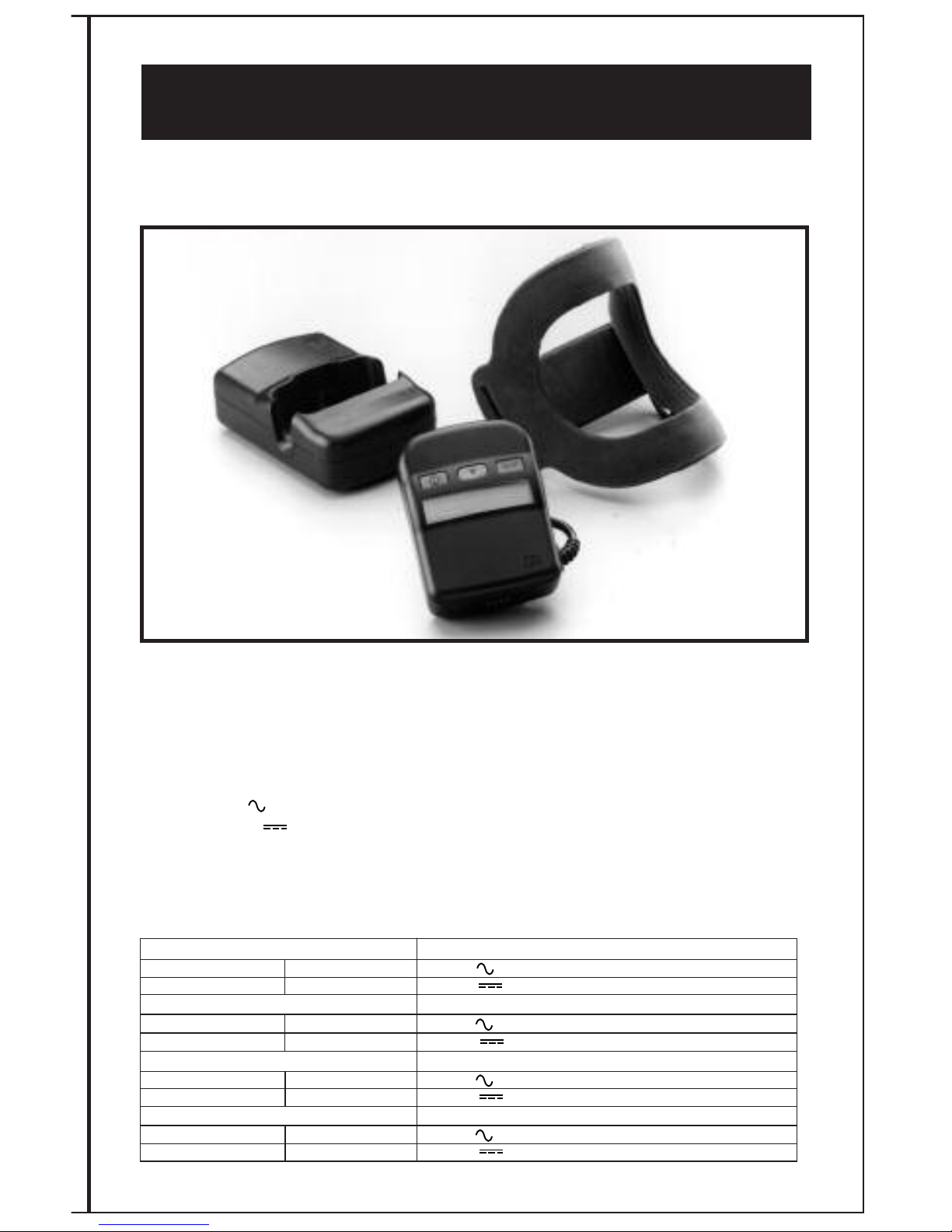
EBI Model 2001 Bone Healing System
®
Model 2001 and FLX®Flexible Treatment Coil
Caution: Federal Law (U.S.A.) restricts this device to sale by or on the order
of a physician. For Prescription Use Only. Single prescription. Single patient
use. Not for re-sale, re-use or re-distribution.
DESCRIPTION
The EBI Bone Healing System®Stimulator promotes healing by inducing weak pulsing
electrical currents at the nonunion fracture site. These signals are generated by a low energy
electromagnetic field created by passing specific electrical current pulses through a flexible
treatment coil.
Electrical Requirements of Model 2001 Power Unit – USA/Americas
Input: 120V 60Hz 36W
Output: 17.8V 1.5A.
Do not use any other power unit with the Model 2001 Bone Healing System.
ELECTRICAL REQUIREMENTS
Use the following power adapters with the Model 2001 Bone Healing System.
Input: 240V 50Hz 36W
Output: 17.8V 1.5A
Model 2001E Europe
Input: 230V 50Hz 36W
Output: 17.8V 1.5A
Model 2001J Japan
Input: 100V 50Hz 36W
Output: 17.8V 1.5A
Model 2001U United Kingdom
Input: 240V 50Hz 36W
Output: 17.8V 1.5A
Model 2001A Australia
Page 7
4
Not for use by patients who are pregnant or becoming pregnant
Not recommended for patients with certain types of pacemakers or implantable defibrillators
SYSTEM COMPONENTS
CONTROL UNIT
The EBI Bone Healing System®Stimulator control unit operates on nickel metal hydride,
rechargeable batteries which allow for ambulatory use. The control unit contains the operating
electronics programmed for the FLX
®
Flexible Treatment Coil. It includes an audible and visible
self checking alarm mechanism to alert the patient if the unit is not functioning properly.
The control unit is designed to store the patient’s daily usage information. Patients are
encouraged to bring the control unit and treatment coil to each follow-up visit to allow the
prescribing physician to review their treatment regimen.
NOTE: The control unit may be worn comfortably on a belt or the waist using the Belt Pouch
when the patient is ambulatory.
BATTERY CHARGER CRADLE
The battery charger cradle is powered by the battery charger/power unit adaptor and is
designed to recharge the control unit batteries. Its design also allows the control unit to be
used in a treat and charge situation (i.e., while sleeping, sitting) (See TREATING AND
CHARGING STEP 3 pg. 11).
BATTERY CHARGER/POWER UNIT
The battery charger/power unit is powered by normal house current and is designed to provide
power to the charger cradle. Power unit must be unplugged from wall outlet to be disconnected.
LINK CABLE
The link cable connects the control unit to its FLX®Flexible Treatment Coil. The link cable
supplied is a 33” (83.8cm) cable. Link cables are also available in 12” and 48” lengths. For
either a 12” (30.5cm) or 48” (121.9cm) cable, phone the Biomet Patient Support Department
at 1-973-299-9300. Outside the United States contact your local EBI/Biomet Distributor.
FLX®FLEXIBLE TREATMENT COIL
The FLX®Flexible Treatment Coil is an encased wire coil that may be incorporated into a cast,
over a cast or brace, or when a cast is not utilized, may be applied directly to the skin. A specific electrical current is delivered to the coil by the control unit. The coil then delivers the therapeutic electromagnetic signal to the nonunion fracture site.
GROUNDING PLUG
This product is equipped with a grounding plug with the exception of the Model 2001E. The
battery charger/power unit should be plugged into a wall outlet that is properly installed and
grounded. In the event of an electrical short circuit, grounding reduces the risk of electric
shock by providing an escape wire for the electric current.
If it is necessary to use an extension cord, use an extension cord that has a 3-blade grounding
plug and a 3-slot receptacle that will accept the plug on the product. Do not use damaged
cords.
Page 8

1. Bassett CAL, N Caulo and J Kort, “Congenital pseudarthrosis of the tibia: Treatment with pulsing
electromagnetic fields”. Clinical Orthop, 154: 136-149,1981.
FULL PRESCRIBING INFORMATION
The mechanism of action behind the PEMF technology involves the upregulation of factors
that modulate normal bone healing. PEMF increases a number of factors such as TGF- ß
1
,
BMP-2 and BMP-4, which are normal physiological regulators of the various stages of bone
healing, including angiogenesis, chondrogenesis and osteogenesis.
INDICATIONS FOR USE
The EBI Bone Healing System®Stimulator is indicated for the treatment of fracture nonunions,
failed fusions, and congenital pseudarthrosis in the appendicular system. A nonunion is
considered to be established when there are no visibly progressive signs of healing. The
original 1979 PMA study included 146 patients with nonunion fractures. These difficult
fractures were characterized as follows: 2.3 average number of prior surgeries and an average
of thirty-seven months (median twenty months) since original injury. These patients were
followed for a minimum of four years (average seven years) from the date of treatment
termination, with a success rate of 63.5%. Even though long term follow-up requirements
were not included in the original study designs, a follow-up rate of 82% was achieved.
Forty-three (43) of the original 48 patients in the congenital pseudarthrosis study were
classified by Bassett
1
who defined the tibial lesions as Type I (n=6), Type II (n=19) and
Type III (n=18), with Type III being the most severe and recalcitrant to treatment. The
success rate for Bassett Type I lesions was 66.7%, Bassett Type II lesions 57.9% and
Bassett Type III lesions 22.2%. The long term post treatment follow-up for the congenital
pseudarthrosis study patient population (n=48) was to skeletal maturity or the age of 18.
The study had an 87.5% follow-up rate.
CONTRAINDICATIONS
A. Nonunion fractures in which a synovial pseudarthrosis (fluid filled gap) exists.
B. Under certain conditions, electromagnetic stimulation could inhibit the output of some
demand pacemakers or implantable defibrillators. Therefore, it is not recommended for
patients with certain types of pacemakers or implantable defibrillators. Patients should
be cautioned to avoid coming in close proximity to pacemaker or defibrillator wearers
during stimulation.
C. Use of the EBI Bone Healing System
®
Stimulator on pregnant patients has not been
evaluated; therefore, it is not recommended in these cases.
WARNINGS
A. The long term effects of exposure to low level magnetic fields are not known. Routine
use of The EBI Bone Healing System
®
Stimulator for over 20 years has indicated no
known risks.
B. During the treatment of patients with open epiphyses, when the epiphysis is in the
pulsing field, physicians are advised that the epiphyseal growth plates should be
monitored for possible effects.
C. Use of the EBI Bone Healing System
®
Stimulator for spine and skull has not been
evaluated.
D. To reduce the risk of potential injury:
1. AVOID touching the battery charger contacts when the battery charger
is plugged into a wall outlet.
2. DO NOT place the battery charger in bed if treating while sleeping.
E. The control unit and battery charger are electrically live when connected
together and the battery charger is plugged into an outlet. To reduce the
risk of serious injury by electric shock patients are advised:
1. DO NOT permit the battery charger to be connected when wet.
2. DO NOT immerse the control unit, the coil or the battery charger in water or any liquid.
5
Page 9
PRECAUTIONS
The following conditions may compromise a successful treatment outcome.
A. Nonunion fractures with gaps in excess of 1 cm.
B. Presence of fixation devices made from magnetic materials.
(Most presently used internal or external fixation devices are
constructed of 316L S.S., titanium alloys, and cobalt-chromium
alloys which are non-magnetic and, therefore, compatible with
the EBI Bone Healing System
®
Stimulator.)
ADVERSE EFFECTS
None known.
6
DIRECTIONS FOR USE
Follow the treatment schedule prescribed by your doctor - normally ten (10) hours per day.
Your compliance with the recommended ten (10) hours per day treatment is very important. A
review of the clinical data demonstrates that less than the recommended use of this device
possibly results in an increase in the time to heal your fracture. (P790002/S012)
If you are unable to treat for ten continuous hours, it is recommended that you break up the
total treatment time into more than one session.
You should:
• Turn the control unit off when finished with your session
• When ready to resume treating, turn the control unit on. The display will indicate the
treatment time you have completed and keep track of your cumulative treatment time for the
day
• If you do not finish ten hours in that day, then use the RESET button to return the time to
zero (See RESET BUTTON)
Remember, if the treatment is administered longer than the prescribed amount (ten hours), the
additional time cannot be applied for future days. Example: If you used the system for multiple sessions totaling 14 hours one day, you should not abbreviate the next day’s cumulative
treatment time to six hours.
For your convenience, your daily treatment time is displayed continuously in hours and
minutes. After ten hours of treatment, the display will read “10:00”, and beep three (3) times,
and then shut off automatically.
Following completion of your daily treatment, you should do the following:
1. Make sure the control unit is off. If you have completed 10 hours, the unit will
automatically shut off. With less than 10 hours of treatment, you will need to manually
turn the control unit off.
2. Insert the control unit firmly into the battery charger cradle to recharge the batteries for
your next treatment (See BATTERY CHARGING).
Page 10

7
FRACTURE HEALING IN RESPONSE TO PEMFs
• Unlike fresh fractures, the healing of nonunions treated with pulsing electromagnetic fields
(PEMFs) does not involve external callus formation. Rather, the healing is more endosteal or
“inside out”, with the changes occurring within the fracture gap tissues and in the adjacent
bone ends.
The bone healing process typically progresses in the following manner under PEMF treatment:
• Triggering calcification of the fibrocartilage in the fracture gap is an early PEMF
effect. Radiographically this calcification is evidenced by the appearance of
fuzziness in the gap space. The fuzziness varies in amount and rate of appearance.
Concurrently, new blood vessels penetrate the calcified fibrocartilage, and the
sclerotic bone flanking the gap begins to resorb (sclerolysis). These effects are
normally observed approximately one to three months after treatment is initiated.
NOTE: This early healing may be disrupted by injudicious loading and motion due to
inadequate immobilization.
The EBI Bone Healing System
®
Stimulator may be used at home or at work. Your schedule
and lifestyle will determine the best time for using the system. Many people find it convenient
to treat while they are sleeping.
• EBI Pre Market Approval Data (P790002/S012)
NOTE: This is a single patient use device, do not reuse. For Prescription Use Only. The EBI
Bone Healing System
®
Stimulator is a durable therapeutic electrical device intended for single
patient use only under a prescription. Treatment at home or in another appropriate or similar
setting is acceptable. The device cannot be reprocessed, i.e., disinfected, sterilized, etc. with
the intent to be used by another patient or for treatment other than prescribed.
RECOMMENDED CONCURRENT FRACTURE MANAGEMENT
The EBI Bone Healing System®Stimulator works best when motion of the fracture site is
minimized or nonexistent. For most patients this immobilization is achieved by applying a well
molded plaster or synthetic cast at the beginning of treatment (together with initial
non-weight bearing, if it is the lower extremity).
The following methods of fracture immobilization have been most effective:
• ankle/tarsals/metatarsals: short leg cast, or rigid internal fixation
• tibia: long leg cast (short leg cast with rigid fixation), or stable
internal fixation or external fixation
• shoulder/clavicle: brace or abduction splint or internal fixation or
figure 8 immobilization
• humerus: stable internal fixation and/or adequate immobilization with controlled rotation
• scaphoid/wrist: long arm cast with thumb spica
(short arm cast with rigid fixation), or stable internal fixation
• carpals/metacarpals/phalanges: cast or internal fixation or external fixation
WEIGHT BEARING GUIDELINES
Immediate weight bearing is recommended for “stable” fractures (less than five degrees
of motion in any plane and/or stable internal fixation). Initial non-weight-bearing is
recommended for “unstable” fractures (greater than five degrees of motion).
Allow six to twelve weeks for the progression of trabecular bridging with the
counterproductive effects of tensile loading (Fuzziness at the fracture gap will be noted
radiographically).
Page 11
8
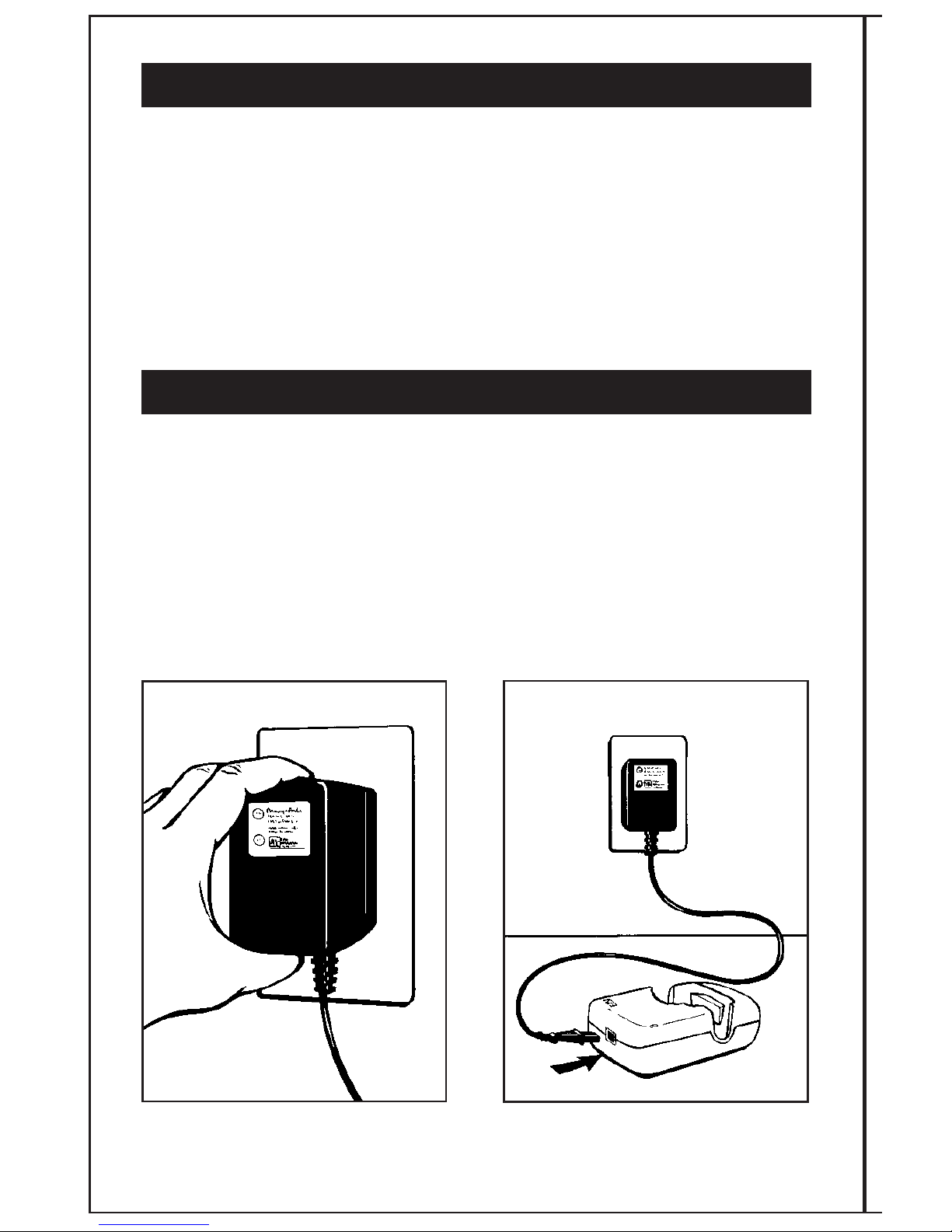
STEP 1:
BATTERY CHARGING
The EBI Bone Healing System®Stimulator runs on nickel metal hydride batteries. Before
treating with the system, the patient will need to charge the batteries to a full charge. At room
temperatures (24˚C [75˚F]), charging may take up to two hours. In warm temperatures (29˚C
[85˚F]), the unit may take up to five hours to charge.
Plug the battery AC charger/power unit
into a grounded wall outlet.
Attach battery AC charger/power unit to
the battery charger cradle.
A
B
FRACTURE HEALING IN RESPONSE TO PEMFs (cont’d)
• The second stage of healing is indicated by the appearance of consolidated
bone stress lines that bridge the fracture gap. This bridging may appear initially,
but should progress until cortical continuity occurs in all cortices as visualized on
AP and lateral x-rays. Once cortical continuity is established and clinical union
occurs (i.e. no motion), the PEMFs treatment may be discontinued. These effects
are normally observed approximately three to eight months after treatment is
initiated. At this point, the patient should be put on a program of guarded
rehabilitation to prevent refracture.
• Subsequent remedullarization and remodeling occurs according to Wolff’s Law
and may take from twelve to twenty-four months to complete.
OPERATING INSTRUCTIONS
Before using the EBI Bone Healing System®Stimulator for the first time, the control unit
should be charged.
Page 12
9
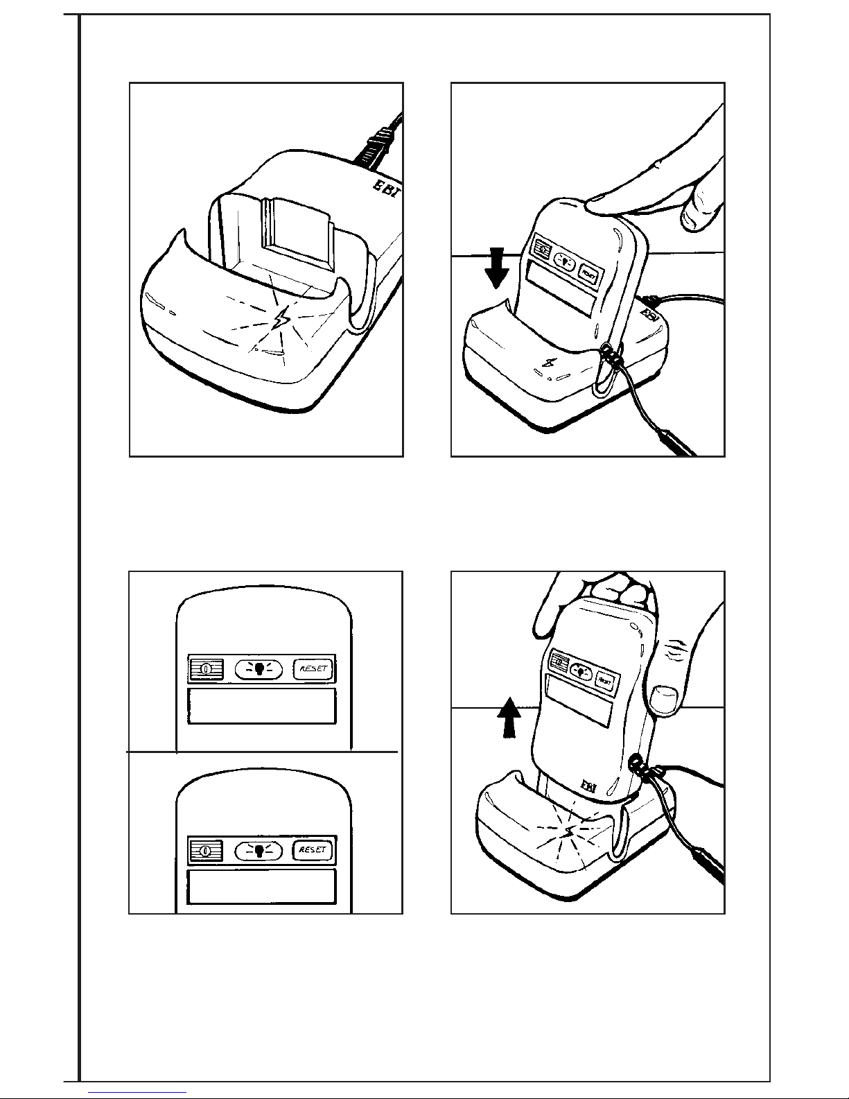
The control unit display will read
“CHARGING”. When the control unit
is fully charged, the display will read
“FULLY CHARGED”. The EBI Bone Healing
System
®
Stimulator is now ready for daily
treatment.
A green light on the cradle will
illuminate indicating that the charger
is connected to household power.
Place the control unit into the battery
charger cradle as illustrated. Make sure
the control unit is turned off.
Remove the control unit from the battery
charger cradle. The control unit is now
ready for connection to the link cable and
treatment coil.
C
D
E
F
FULLY CHARGED
CHARGING
Page 13
10
STEP 2:
PREPARING THE SYSTEM TO BEGIN TREATMENT
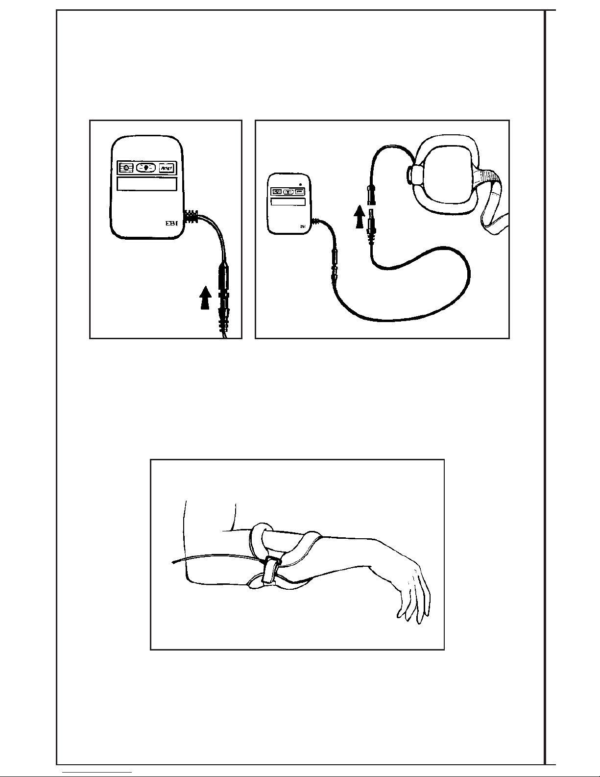
The link cable arrives disconnected from the control unit.
Connect one end of the link
cable to the control unit cable
as illustrated.
After confirming that the link cable is properly
connected to the control unit, connect the other
end of the link cable to the FLX
®
Flexible Treatment Coil.
This connection allows for simple quick disconnect and
reconnect by the patient.
Next, position the FLX
®
Flexible Treatment Coil over the fracture
site. The entire fracture site should be centered within the coil
treatment window.
A
B
C
Page 14
11
STEP 4:
RECHARGING THE BATTERIES
The average daily treatment time supplied by the batteries in the control unit will vary according
to the size of FLX
®
coil being used. All coils should deliver a minimum treatment time of ten
hours per charge, except the FLX
®
5, which will deliver five hours of treatment per charge. At
room temperatures (24°C [75°F]), charging may take up to two hours. In warm temperatures
(29°C [85°F]), the unit may take up to five hours to charge.
After daily treatment, patients should do the following:
A. Turn the control unit off.
B. Follow instructions A-E from Step 1 (Pages 8 & 9).
C. It is not necessary to disconnect the control unit from the charger cradle
once fully charged. The control unit can remain in the battery charger cradle
until the patient’s next treatment session.
NOTE: The batteries cannot be overcharged. If the control unit is in the battery charger cradle
and the batteries are already fully charged, the charger will terminate the recharging process
early. This will be indicated by the control unit display reading “FULLY CHARGED” when
charging is complete. Therefore, do not be concerned if the batteries are inadvertently
charged more than once.
STEP 3:
TREATING AND CHARGING
Patients may treat with the system while recharging the batteries. When the patient treats and
charges at the same time, the treatment time and charging message will be displayed. To treat
and charge, patients should:
1. Turn the control unit on.
2. Follow instructions A - E from Step 1. (Page 8)
NOTE: If treating while the control
unit is connected to the battery
charger cradle, the control unit display
will read “TREATING 00:00 and
CHARGING”. Once the patient has
completed the treatment, he should
turn the control unit off, and leave it
connected to the battery charger cradle
to continue charging the batteries, if it
is not displaying “FULLY CHARGED”.
TREATING 00:00
AND CHARGING
Page 15
12
When the batteries need recharging, the following will occur:
1. The display will read “RECHARGE
BATTERY” and 10 short beeps will
sound. After 10 seconds, the beep
will stop and the display will shut off.
2. Until the batteries are recharged,
“RECHARGE BATTERY” will appear
on the display each time the control
unit is turned on. After the third time
the patient turns the unit on without
recharging, “RECHARGE BATTERY”
will appear and alternate with “PLEASE
CALL EBI 1-800-526-2579”. If patients
need assistance with recharging, they
should call the 800 number and ask to
speak to a Patient Support Representative.
Outside the United States contact your
local EBI/Biomet Distributor, or
call 1-973-299-9300.
3. Only after the patient places the control unit
into the battery charger cradle for recharging
will the message automatically clear.
4. When the control unit has been
fully charged, it may be removed
for ambulatory treatment, or left
in the battery charger cradle and
turned on for nonambulatory use.
NOTE: Every 14 days the charger will
automatically refresh the batteries by
completely depleting them before it begins
charging. When this occurs, the control
unit display will read “REFRESHING”.
Once the system has refreshed the
batteries, the control unit display will read
“CHARGING”, and the charging process
will begin. The refresh mode will take a
few hours depending on the size of the
FLX
®
Flexible Treatment Coil being used.
CHARGING
REFRESHING
Alternates with
RECHARGE BATTERY
PLEASE CALL EBI
1-800-526-2579
Page 16
13
KEYPAD FUNCTIONS
ON/OFF BUTTON
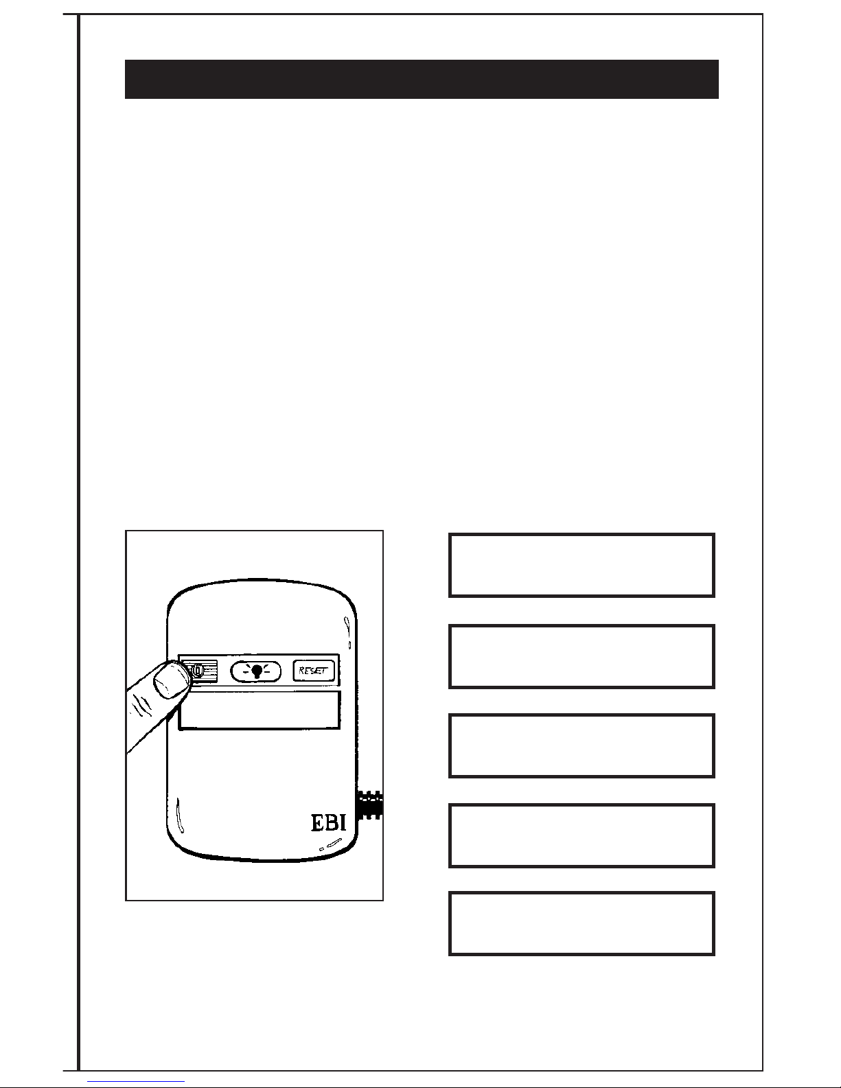
Each time the ON/OFF button is pressed, an audible beep will be heard. To turn the control
unit on, press the on/off button one time. Pressing this button a second time will turn the
system off. Every time the control unit is turned on, the display will indicate the following
sequence:
1. “EBI RECOMMENDS 10 HOURS PER DAY” for the 2001 BHS.
2. “AVG HR/DAY 00:00” - This is the daily treatment average
since the patient’s treatment started.
3. “DAYS USED 000” - This is the total number of days of treatment.
4. “DAYS UNUSED 000” - This is the total number of days when
there was no treatment.
5. “TREATING 00:00” - This is the cumulative number of hours
of treatment in the present or previous treatment session,
provided that the reset button has not been pressed
(see RESET BUTTON).
1.
2.
3.
4.
5.
EBI RECOMMENDS
10 HOURS PER DAY
PATIENT USAGE
AVG HR/DAY 00:00
PATIENT USAGE
DAYS USED 000
PATIENT USAGE
DAYS UNUSED 000
TREATING 0:00
Page 17
14
RESET BUTTON
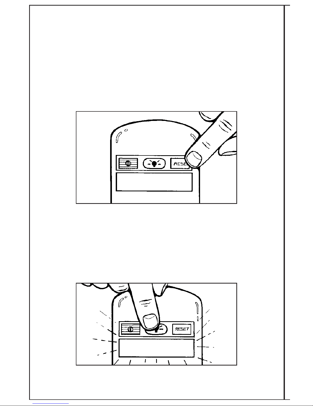
The system is designed with a reset function to allow the daily timer to be reset to zero.
Should the patient not finish the ten hours of treatment in one day, he/she presses the RESET
button for two (2) beeps and the daily timer will go back to zero in preparation for the next
treatment session. The treatment time will be retained on the display unless the RESET button
is depressed for two audible beeps.
To avoid the accidental reset of the daily time, the RESET button has a one second delay.
When pressed, the RESET button will beep. To clear the time back to zero, continue holding
the button until a second beep is heard (approximately one second). Release the RESET
button. This will clear the time back to 0:00. The display will then read “TREATING 0:00”.
BACKLIGHT BUTTON
The system is designed with a backlight function to enhance the visibility of the LCD display
in dim lighting. When pressed the BACKLIGHT button will beep, and the backlight will turn on
for 5 seconds.
TREATING 0:00
Page 18
15
TROUBLESHOOTING SYSTEM MESSAGES
Allow up to one minute for the display message to change after taking corrective action.
• “RECHARGE BATTERY” If this message appears, the batteries need to be recharged.
This message will only appear during a treatment session. In order to recharge the
batteries and continue treatment, ensure that the control unit is on. Refer to Step 4
“RECHARGING THE BATTERIES” (P. 11), repeating 1-4.
RECHARGE BATTERY
Following completion of your daily treatment, you should do the following:
1. Make sure the control unit is off. If you have completed 10 hours, the unit will
automatically shut off. With less than 10 hours of treatment, you will need to manually
turn the control unit off.
2. Insert the control unit firmly into the battery charger cradle to recharge the batteries for
your next treatment (See BATTERY CHARGING).
The EBI Bone Healing System
®
Stimulator may be used at home or at work. Your schedule
and lifestyle will determine the best time for using the system. Many people find it
convenient to treat while they are sleeping.
Page 19
16
“
CHECK CONNECTORS SEE MANUAL”
This message, accompanied by 10 short audible
beeps, appears when the control unit is not
properly connected to the FLX
®
Flexible
Treatment Coil. Be sure to check all connections
between the control unit, link cable and the
treatment coil. If the connection is not made,
the unit will turn itself off. When the unit is
turned back on and the message continues,
check all connections again. If the problem is
not corrected and the connection is not made,
the message will stay on the display for 10
seconds and then turn off each time the control unit is turned on. After the third time of
turning the unit on without correcting the problem, “CHECK CONNECTORS SEE MANUAL” will
appear and alternate with “PLEASE CALL EBI 1-800-526-2579”. If you need assistance, you
should call the 800 number and ask to speak to a Patient Support Representative. Outside the
United States contact your local EBI/Biomet Distributor, or call 1-973-299-9300.
”CHECK COIL SEE MANUAL”
This message, accompanied by ten short audible
beeps, appears when the FLX
®
Flexible Treatment
Coil is damaged or inappropriately flexed. The
message will stay on the display for 10 seconds
and then turn off each time the control unit is
turned on. After the third time of turning the unit
on without correcting the problem, “CHECK COIL
SEE MANUAL” will appear and alternate with
“PLEASE CALL EBI 1-800-526-2579”. If you
need assistance, you should call the 800 number
and ask to speak to a Patient Support
Representative. Outside the United States contact
your local EBI/Biomet Distributor, or call 1-973-299-9300.
“CANNOT TREAT PLEASE CALL EBI 1-800-526-2579”
This message, accompanied by ten short audible
beeps, appears when there is a hardware
problem within the control unit. The message
will stay on display for 10 seconds and then turn
off each time the control unit is turned on. After
the third time of turning the unit on without
correcting the problem, “CANNOT TREAT” will
appear and alternate with “PLEASE CALL EBI
1-800-526-2579”. If you need assistance, you
should call the 800 number and ask to speak to
a Patient Support Representative. Outside the United
States contact your local EBI/Biomet Distributor, or
call 1-973-299-9300.
CHECK CONNECTORS
SEE MANUAL
PLEASE CALL EBI
1-800-526-2579
Alternates with
CANNOT TREAT
PLEASE CALL EBI
1-800-526-2579
Alternates with
CHECK COIL
SEE MANUAL
PLEASE CALL EBI
1-800-526-2579
Alternates with
Page 20
17
“
CANNOT CHARGE PLEASE CALL EBI 1-800-526-2579”
This message, accompanied by 10 short audible
beeps, appears when temperature is over 38
degrees C, under 0 degrees C or there is a
hardware problem within the charger. The
message will stay on the display for 10 seconds
and then turn off each time the control unit is
turned on. After the third time of turning the
unit on without correcting the problem,
“CANNOT CHARGE” will appear and alternate
with “PLEASE CALL EBI 1-800-526-2579”.
If you need assistance, you should call the 800
number and ask to speak to a Patient Support
Representative. Outside the United States contact
your local EBI/Biomet Distributor, or call
1-973-299-9300.
“SYSTEM ENDPOINT 400 DAYS”,
“PLEASE CALL EBI 1-800-526-2579”
When the control unit reaches 400 days of
treatment, the treatment signal is locked off.
The display will read “SYSTEM ENDPOINT 400
DAYS” followed by “PLEASE CALL EBI 1-800526-2579”. The display will turn off. This
message will appear every time the control unit
is turned on. At this point, the system should be
discarded. It is recommended that you contact
your Doctor’s office to inform him/her that you
have reached this point in your treatment. See
p.64 for Disposal Instructions. Outside the United States
contact your local EBI/Biomet Distributor, or call
1-973-299-9300.
CANNOT CHARGE
PLEASE CALL EBI
1-800-526-2579
Alternates with
Until 3rd time
SYSTEM ENDPOINT
400 DAYS
PLEASE CALL EBI
1-800-526-2579
Alternates with
Page 21
18
FLX®FLEXIBLE TREATMENT COILS
The FLX®Flexible Treatment Coil included with this EBI Bone Healing System®Stimulator was
specifically chosen by Biomet based upon the location of the fracture, the vertical length of the
fracture, the depth of signal penetration required to treat the fracture, and the anatomical size
of the patient.
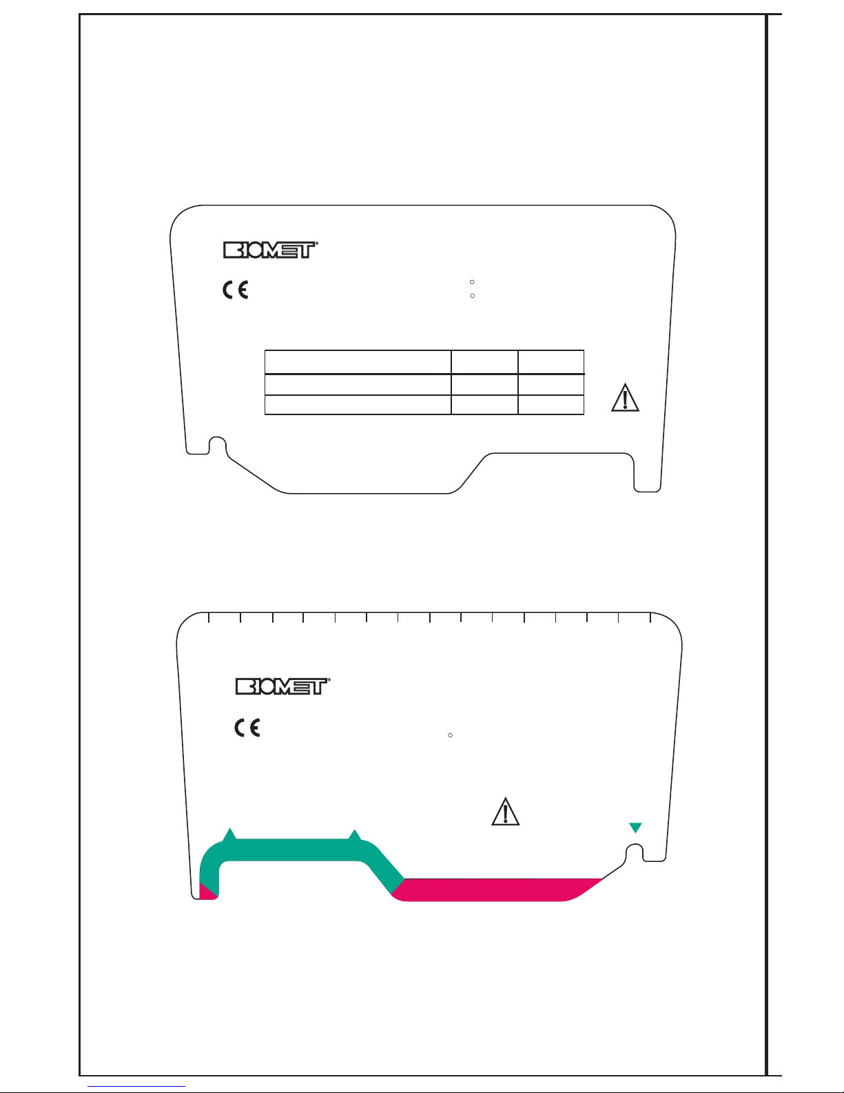
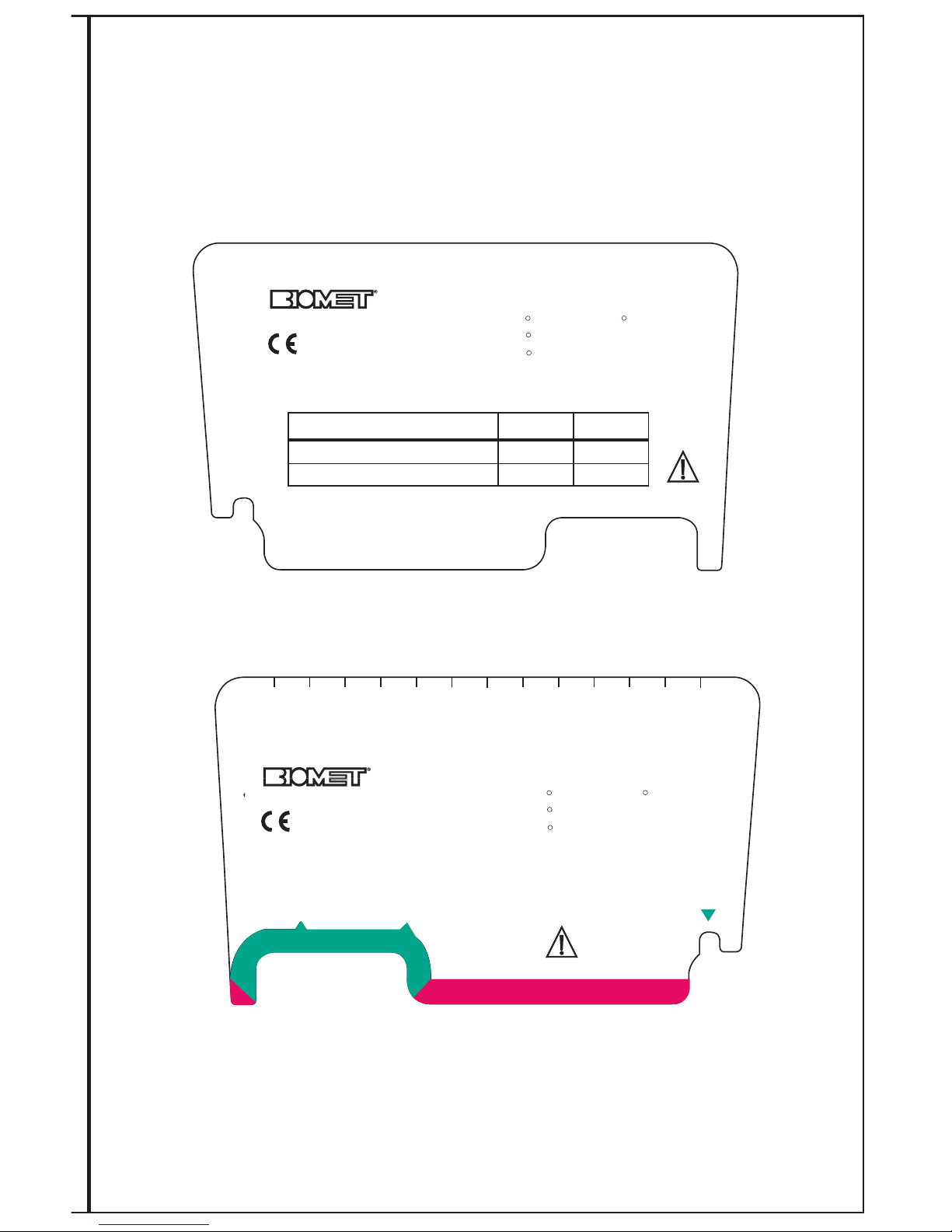
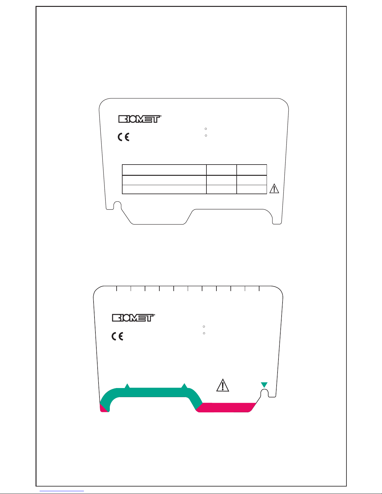
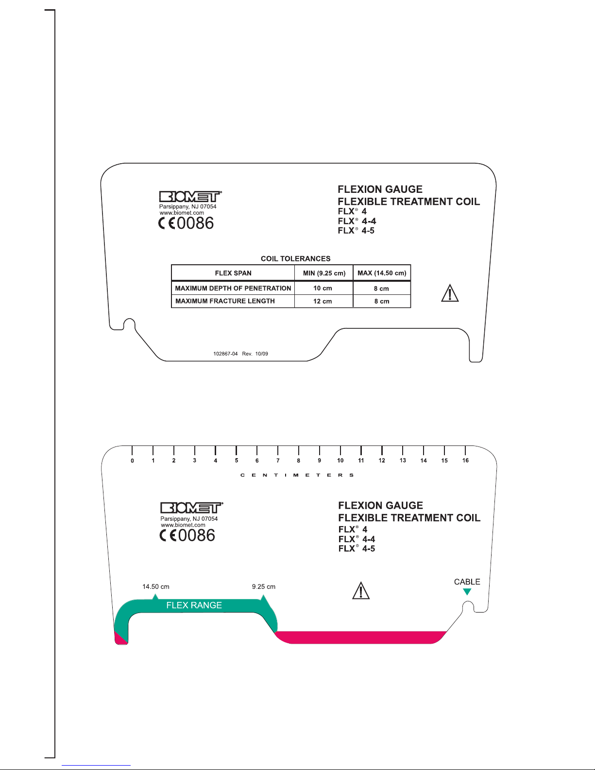
NOTE: Included in each system is a Flexion Gauge for measuring the tolerances of the coil.
The coil should not be flexed beyond the Flex Range of the gauge (the area indicated by green
color).
DEPTH OF PENETRATION SPECIFICATIONS FOR FLX
®
FLEXIBLE TREATMENT
COILS FLX®1, 2, 3, 4, 5, AND COILETTE COILS TOLERANCES
FLX®Coil M/L Flexion Depth of Vertical Fracture
Penetration Length
FLX
®
Mini Coilette Minimum 2.5cm 2.5 cm 1.5 cm
(
Phalangeal) Maximum 3.5cm 2 cm 1.5 cm
FLX
®
Coilette Flat N/A 2.75 cm 4 cm
(Small bones) Elliptical N/A 3.5 cm 4 cm
Saddle N/A 3.5 cm 2 cm
FLX
®
XL Flat N/A 3.5 cm 6 cm
Coilette Elliptical 5 cm 4.25 cm 6 cm
Saddle 7.5 cm 5.5 cm 4 cm
FLX
®
1 Minimum 9 cm 6.5 cm 7 cm
(Scaphoid) Maximum 13 cm 5.5 cm 6 cm
FLX®1-1 Minimum 8 cm 5 cm 12 cm
(Elliptical) Maximum 10 cm 4 cm 12 cm
FLX®1-2 Minimum 9 cm 6.5 cm 7 cm
(Metatarsal) Maximum 13 cm 5.5 cm 6 cm
FLX®1-3 Minimum 120° 3 cm 5 cm
(Clavicle) Maximum 150° 3 cm 5 cm
FLX®2 Minimum 8 cm 8 cm 10 cm
Maximum 11 cm 7 cm 10 cm
FLX®2-1 Minimum 10 cm 5 cm 16 cm
(Elliptical) Maximum 12 cm 4.5 cm 14 cm
FLX
®
2-2 Minimum 8 cm 8 cm 10 cm
(Metatarsal) Maximum 11 cm 7 cm 10 cm
FLX®2-3 Minimum 120º 4 cm 8 cm
(Clavicle) Maximum 150º 4 cm 8 cm
FLX®2-4 Minimum 8 cm 8 cm 10 cm
(Ankle) Maximum 11 cm 7 cm 10 cm
FLX®2-5 Minimum 8 cm 8 cm 10 cm
(Shoulder) Maximum 11 cm 7 cm 10 cm
FLX®3 Minimum 5 cm 7 cm 7 cm
Maximum 9 cm 5.5 cm 6 cm
FLX®3-5 Minimum 5 cm 7 cm 7 cm
(Shoulder) Maximum 9 cm 5.5 cm 6 cm
FLX®4 Minimum 9.25 cm 10 cm 12 cm
Maximum 14.5 cm 8 cm 8 cm
FLX®4-1 Minimum 12 cm 6 cm 22 cm
(Elliptical) Maximum 14 cm 6 cm 18 cm
FLX®4-4 Minimum 9.25 cm 10 cm 12 cm
(Ankle) Maximum 4.5 cm 8 cm 8 cm
FLX®4-5 Minimum 9.25 cm 10 cm 12 cm
(Shoulder) Maximum 14.5 cm 8 cm 8 cm
FLX®5 Minimum 13 cm 12 cm 10 cm
(Femur) Maximum 20 cm 10 cm 10 cm
Page 22
Coil Application Instructions for the FLX®-1, FLX®-2, FLX®-3, FLX®-4 and FLX®-5 Coils
Applies to:
Assembly # Description Coil Replacement # Suggested Placement
5001 FLX
®
-1 0100 Metatarsals, Radius, Ulna,
Scaphoid, Metacarpals
5210 FLX
®
-2 0200 Humerus, Tibia, Fibula, Radius, Ulna
5310 FLX
®
-3 0300 Radius, Ulna, Humerus, Metatarsals,
Tibia/Fibula
5410 FLX
®
-4 0400 Femur, Tibia/Fibula, Humerus
5510 FLX
®
-5 5500 Femur
19
S
pecialty coils are for applications where the standard straps may be too difficult to apply.
Each specialty FLX
®
coil features one (1) snap at all four corners of the coil and comes
pre-assembled to fit the right side of the body but the same straps may be easily switched
for left side applications.
NOTE: Not all coils need to have straps switched.
Fracture Type Specialty Coil Type
Long Vertical Fractures FLX
®
1-1 or 2-1 or 4-1
Metatarsals FLX
®
2-1 or 2-2
Clavicle FLX
®
1-3 or 2-3
Ankle/Elbow FLX
®
2-4 or 4-4
Proximal Humerus/Shoulder FLX
®
2-5 or 3-5 or 4-5
Page 23

20
Flexion Gauge Instructions for FLX®-1, FLX®-2, FLX®-3, FLX®-4 & FLX®-5 Coils
In order to ensure proper fit and efficacious treatment, the Flexion Gauge should be checked
for the proper shape.
1) Place the coil at the treatment site and shape for best fit. Coil should be bent only
in one direction. Do not kink or twist the coil.
2) Remove the shaped coil and place edge closest to the connector cable into the
slot/notch on the right hand side of the Flexion Gauge marked with a green
triangle. The opposite coil edge should fall within the green zone in the area
marked “FLEXION RANGE”. Each Flexion Gauge has a chart of coil tolerances
with depth of penetration data.
3) If the coil edge does not fall within the green zone, contact your Biomet
representative for a suitable replacement and assistance.
Refer to pages 24-28 for diagrams of the Flexion Gauges.
Page 24
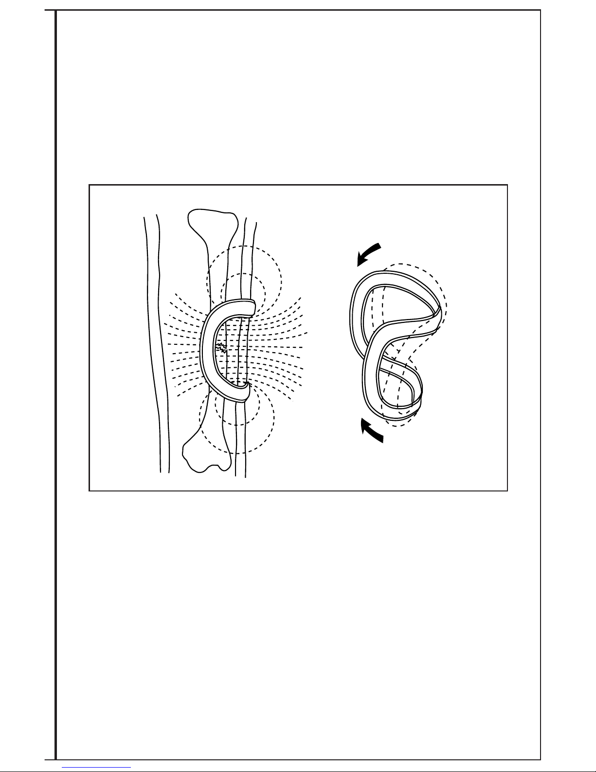
21
FLX®COIL APPLICATIONS
It is necessary that the entire fracture site receive a therapeutic pulsing field. This is
accomplished by placing the treatment coil over the fracture site. Ensure that the entire
fracture is centered within the treatment coil window. The coil is designed to permit
routine follow-up examination by x-ray.
CONFORMING THE FLX®COIL
The FLX®coil is easily conformable so it may be shaped to the surface anatomy of the
fracture site being treated. The coil is also rigid enough to retain its shape once conformed.
The lightweight, low, flat profile makes the coil easy to apply and more comfortable for the
patient to wear.
The coil is designed to be bent in only one direction (single plane, see illustration).
It should not be twisted or kinked.
Page 25
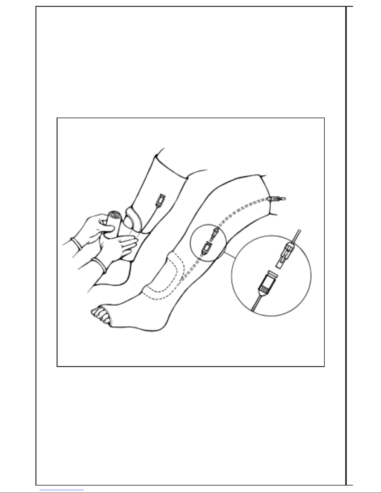
22
CASTED APPLICATIONS:
1. Apply 1-2 rolls of casting material (synthetic or plaster) in the usual manner and
allow it to set. Center the coil over the fracture site, confirming correct placement
with an x-ray if necessary.
2. Incorporate the coil into the cast with an additional wrap of casting material.
3. Position the connector mounting assembly near the coil and incorporate it into
the cast with additional cast material.
SPECIAL NOTE: If patient compliance with the system is not a concern, the treatment coil
may be placed on top of a cast or brace. Be sure to mark the coil placement with an indelible
marker for easy refitting by the patient.
Page 26
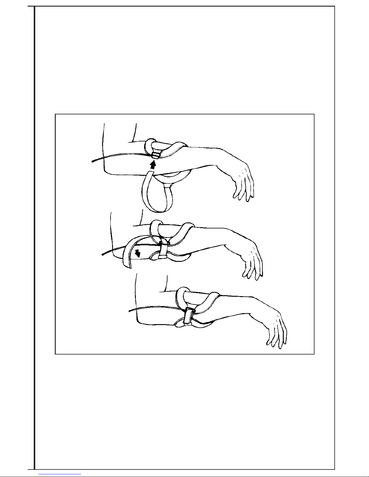
NONCASTED APPLICATIONS:
1. If using the coil directly on the skin, place the foam padding inside the coil.
2. Position the FLX
®
coil over the fracture site. The entire fracture site should be
centered within the coil treatment window.
3. Attach and secure the FLX
®
coil around the extremity with the Velcro®strap
or the garment to give the patient a snug yet comfortable fit.
NOTE: To allow flexibility in positioning, the treatment coil was designed with a large
treatment window. However, it is recommended that the center of the coil be positioned
over the fracture site.
23
Page 27
24
COIL TOLERANCES
FLEX SPAN
M
IN (9 cm)
MAX (13 cm)
MAXIMUM DEPTH OF PENETRATION
MAXIMUM FRACTURE LENGTH
6.5 cm
7 cm
5.5 cm
6 cm
FLEXION GAUGE
FLEXIBLE TREATMENT COIL
FLX 1
R
FLX 1-2
R
FLEXION GAUGE
FLEXIBLE TREATMENT COIL
13 cm
9 cm
CABLE
102867-01 Rev. 10/09
0
1
2
3
4
5
6
7
8
9
10 11
12
13
14
C
ENTIMETERS
Parsippany, NJ 07054
FLEX RANGE
www.biomet.com
0086
FLX 1
FLX 1-2
R
Parsippany, NJ 07054
www.biomet.com
0086
FLEX RANGE
Front View
Back View
Not to scale
Page 28
25
FLEXION GAUGE
FLEXIBLE TREATMENT COIL
FLX 2
R
FLX 2-2
R
FLX 2-4
R
FLX 2-5
R
C
OIL TOLERANCES
FLEX SPAN MIN (8 cm)
MAX (11 cm)
MAXIMUM DEPTH OF PENETRATION
MAXIMUM FRACTURE LENGTH
8 cm
10 cm
7 cm
10 cm
102867-02 Rev. 10/09
CABLE
11 cm 8 cm
FLEXION GAUGE
FLEXIBLE TREATMENT COIL
FLX 2
R
FLX 2-2
R
FLX 2-4
R
FLX 2-5
R
C
ENTIMETERS
0
1
2
3
4
5
6
7
8
9
10
11
12
FLEX RANGE
Parsippany, NJ 07054
www.biomet.com
0086
Parsippany, NJ 07054
www.biomet.com
0086
Front View
Back View
Not to scale
Page 29
26
FLEXION GAUGE
FLEXIBLE TREATMENT COIL
FLX 3
R
FLX 3-5
R
COIL TOLERANCES
FLEX SPAN MIN (5 cm)
M
AX (9 cm)
MAXIMUM DEPTH OF PENETRATION
MAXIMUM FRACTURE LENGTH
7 cm
7 cm
5
.5 cm
6 cm
1
02867-03 Rev. 10/09
FLEXION GAUGE
FLEXIBLE TREATMENT COIL
FLX 3
R
FLX 3-5
R
CABLE
5 cm
9 cm
0
1
2
3
4
5
6
7
8
9
10
CENTIMETERS
FLEX RANGE
Parsippany, NJ 07054
www.biomet.com
0086
Parsippany, NJ 07054
www.biomet.com
0086
Front View
Back View
Not to scale
Page 30
27
Front View
Back View
Not to scale
Page 31
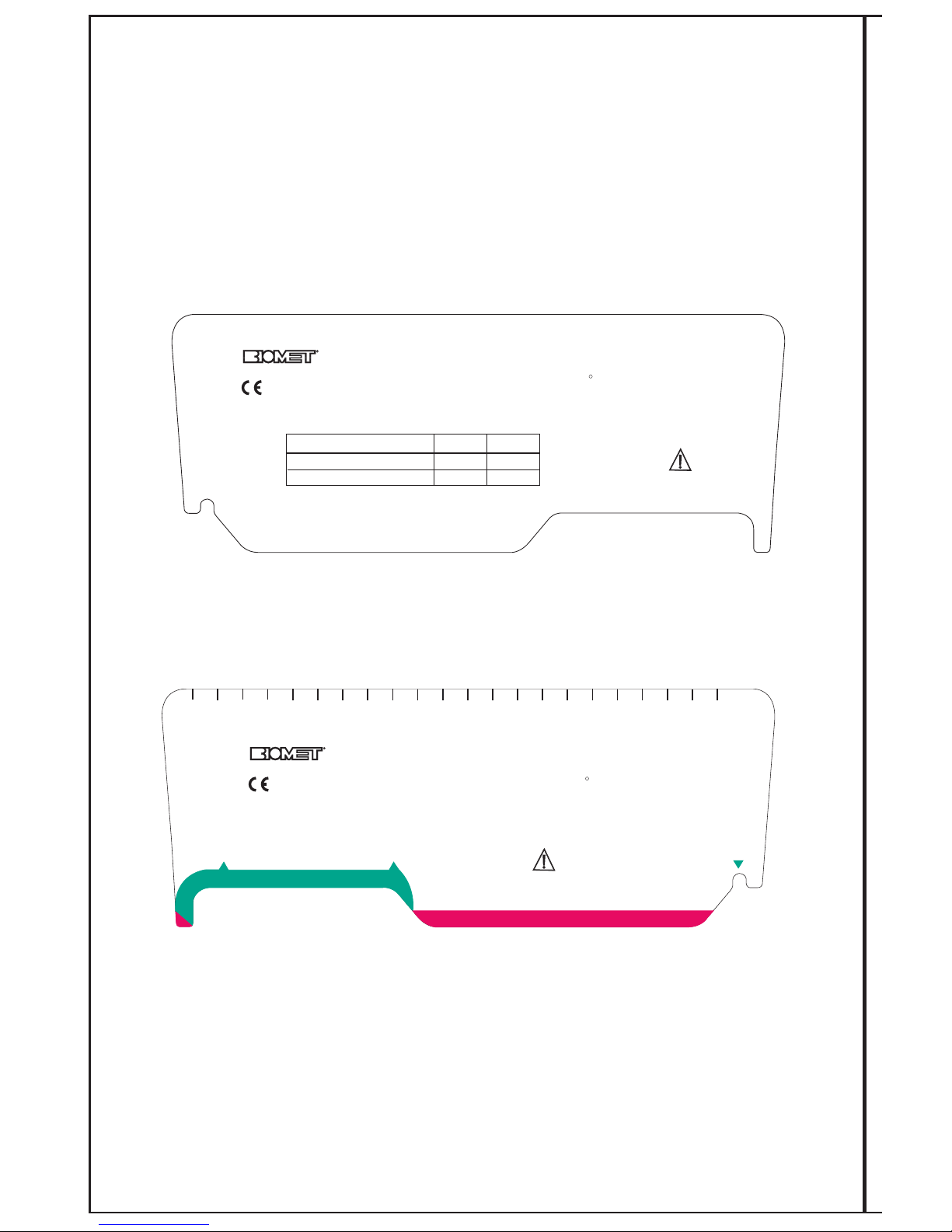
28
FLEX RANGE
13 cm
20 cm
FLEXION GAUGE
FLEXIBLE TREATMENT COIL
FLX 5
R
CABLE
CENTIMETERS
0
1
2
3
4
5
67
8
9
10
1
112
13
1
4
15
16
17
18
19
2
0
21
Parsippany, NJ 07054
www.biomet.com
0086
F
LEXION GAUGE
FLEXIBLE TREATMENT COIL
F
LX 5
R
COIL TOLERANCES
FLEX SPAN MIN (13 cm)
M
AX (20 cm)
M
AXIMUM DEPTH OF PENETRATION
MAXIMUM FRACTURE LENGTH
1
2 cm
1
0 cm
10 cm
1
0 cm
P
/N 102867-05 Rev. 10/09
P
P
arsippany, NJ 07054
w
ww.biomet.com
0086
Front View
Back View
Not to scale
Page 32
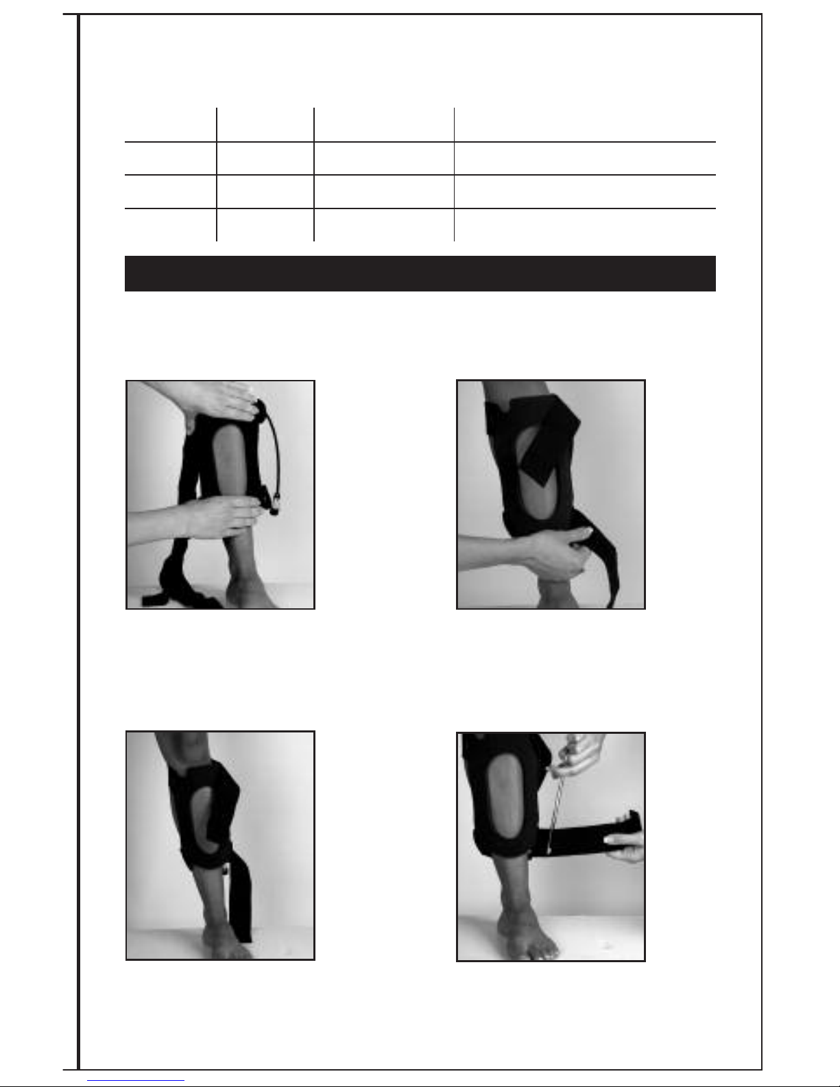
29
Coil Application Instructions
Applies to:
Assembly # Description Coil Replacement # Suggested Placement
5111 FLX
®
1-1 0101 Radius, Ulna, Malleolus (M/L)
5211 FLX
®
2-1 0201 Tibia, Fibula, Radius, Ulna
5411 FLX
®
4-1 0401 Humerus, Tibia, Fibula, Radius, Ulna,
See Flexion Gauge Instructions for measuring the tolerances of the coil on page 31-33.
Used for long vertical fracture lengths: comminuted and segmented fracture applications.
Position coil so that it covers the entire fracture
length, according to physician instructions
(Position coil with cable toward waist).
Make sure coil is firmly in place before
securing straps.
Bring top and bottom straps around
back to opposite side.
Press strap onto Velcro
®
hook. Readjust
both straps for a secure, comfortable fit.
DO NOT over tighten.
Cut excess straps to size.
12
3
FLX®1-1 OR 2-1 OR 4-1 LONG VERTICAL FRACTURE APPLICATION
2
4
Page 33

30
Flexion Gauge Instructions for FLX®1-1, FLX®2-1 & FLX®4-1 Coils
In order to ensure proper fit and efficacious treatment, the Flexion Gauge should be checked
for the proper shape.
1) Place the coil at the treatment site and shape for best fit. Coil should be bent only in
one direction. Do not kink or twist the coil.
2) Remove the shaped coil and place edge closest to the connector cable into the
slot/notch on the right hand side of the Flexion Gauge marked with a green triangle.
The opposite coil edge should fall within the green zone in the area marked
“FLEXION RANGE”. Each Flexion Gauge has a chart of coil tolerances with depth
of penetration data.
3) If the coil edge does not fall within the green zone, contact your Biomet
representative for a suitable replacement and assistance.
Refer to pages 31-33 for diagrams of these Flexion Gauges.
Page 34
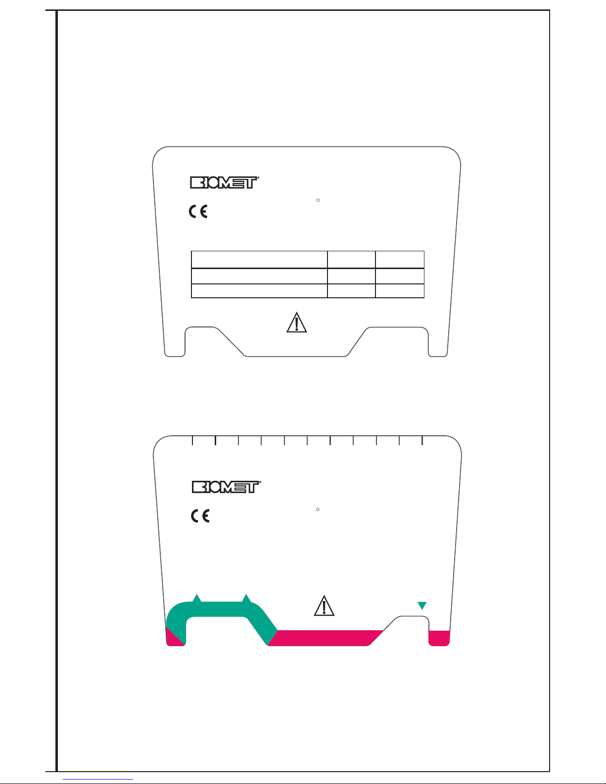
31
FLEX RANGE
10 cm 8 cm
FLEXIBLE TREATMENT COIL
FLX 1-1
R
CENTIMETERS
0
1
2
3
4
5
67
8
9
10
Parsippany, NJ 07054
www.biomet.com
0086
FLEXION GAUGE
Front View
Back View
C
OIL TOLERANCES
FLEX SPAN
MIN (8 cm)
MAX (10 cm)
MAXIMUM DEPTH OF PENETRATION
MAXIMUM FRACTURE LENGTH
5 cm
12 cm
4
cm
12 cm
102867-11 Rev. 10/09
FLEXIBLE TREATMENT COIL
FLX 1-1
R
FLEXION GAUGE
Parsippany, NJ 07054
www.biomet.com
0086
Not to scale
Page 35
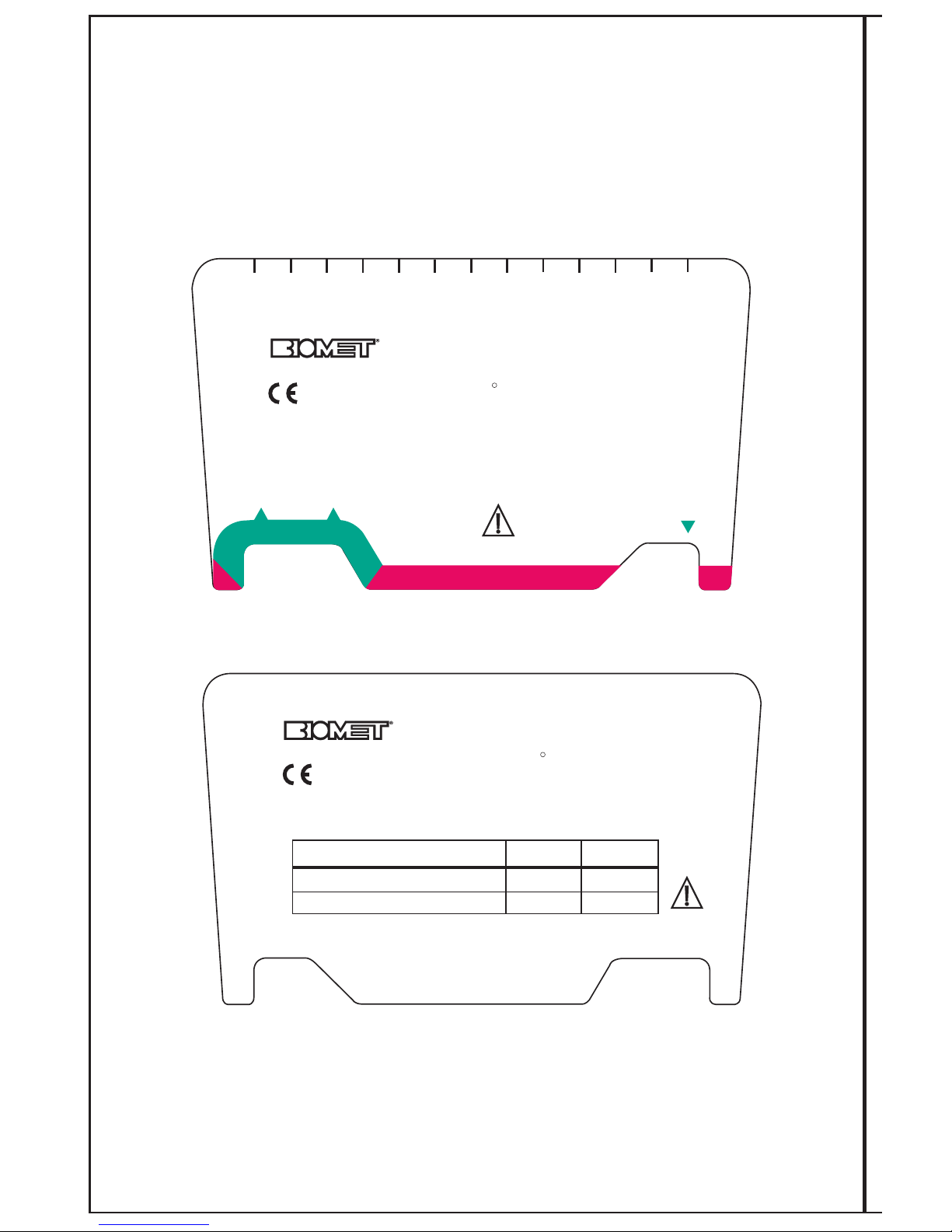
32
COIL TOLERANCES
FLEX SPAN
MIN (10 cm)
MAX (12 cm )
MAXIMUM DEPTH OF PENETRATION
MAXIMUM FRACTURE LENGTH
5 cm
16 cm
4.5 cm
14 cm
FLEXIBLE TREATMENT COIL
FLX 2-1
R
FLEX RANGE
10 cm
12 cm
CENTIMETERS
102867-21 Rev. 10/09
0
1
2
3
45
6
7
8
9
10
1
1
1
2
0086
Parsippany, NJ 07054
www.biomet.com
FLEXION GAUGE
FLEXIBLE TREATMENT COIL
FLX 2-1
R
FLEXION GAUGE
0086
Parsippany, NJ 07054
www.biomet.com
Front View
Back View
Not to scale
Page 36
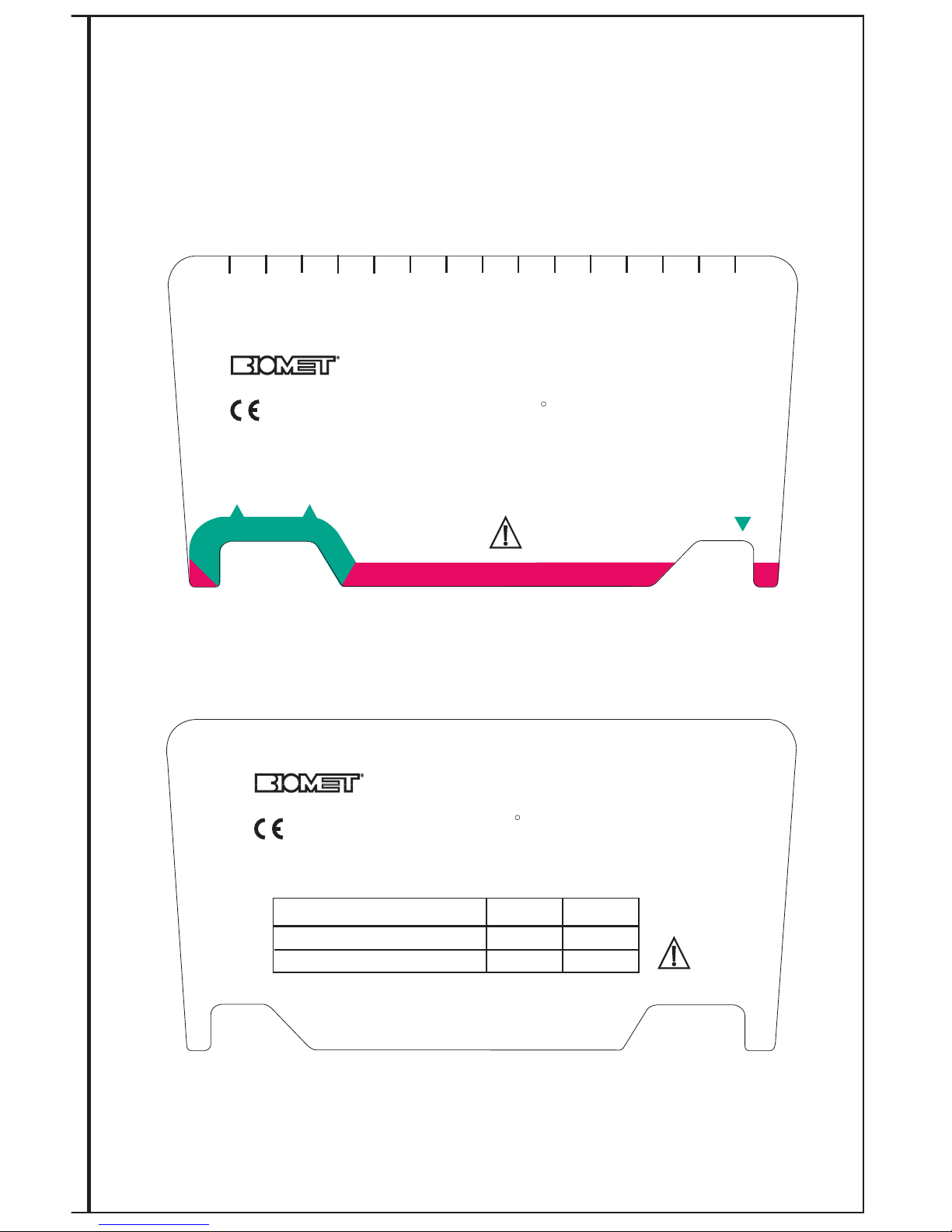
33
FLEXION GAUGE
FLEXIBLE TREATMENT COIL
FLX 4-1
R
COIL TOLERANCES
FLEX SPAN
MIN (12 cm)
MAX (14 cm)
MAXIMUM DEPTH OF PENETRATION
MAXIMUM FRACTURE LENGTH
6 cm
22 cm
6 cm
18 cm
14 cm 12 cm
FLEX RANGE
CENTIMETERS
012 3
4
5
6
7
8910
11
12 13
14
102867-41 Rev. 10/09
0086
Parsippany, NJ 07054
www.biomet.com
0086
Parsippany, NJ 07054
www.biomet.com
FLEXION GAUGE
FLEXIBLE TREATMENT COIL
FLX 4-1
R
Front View
Back View
Not to scale
Page 37
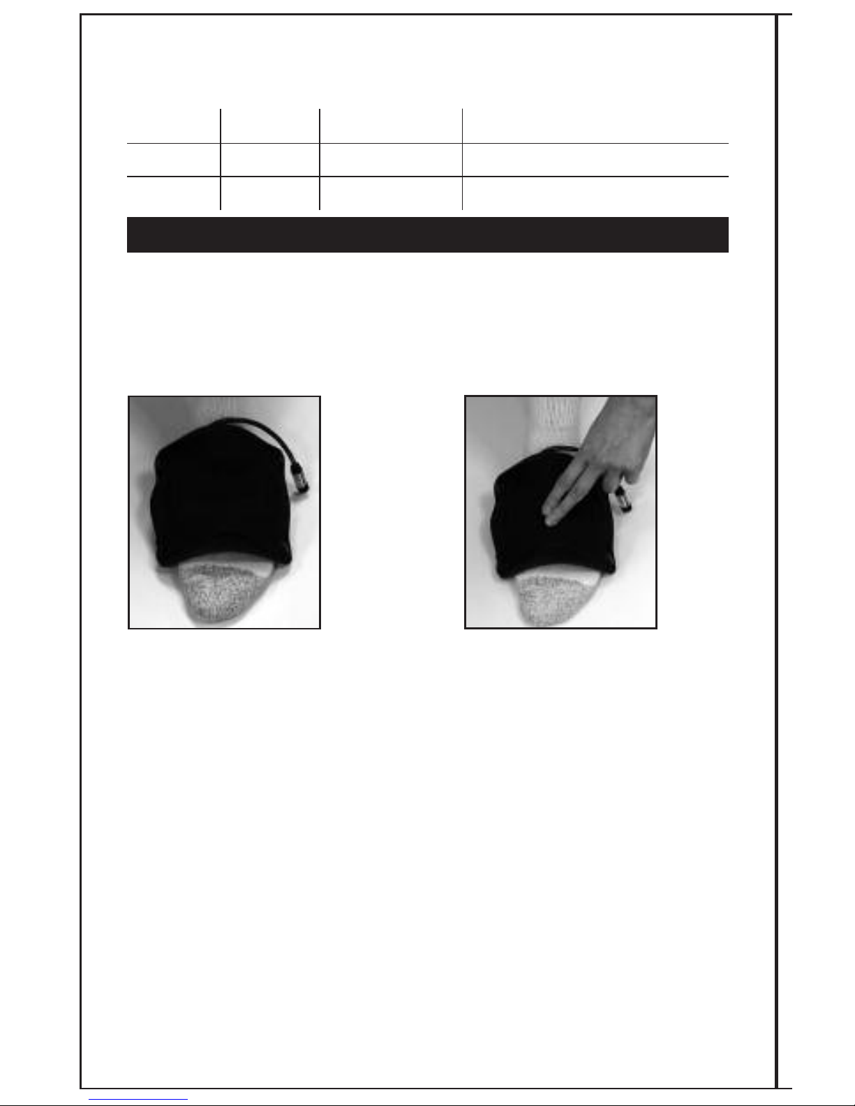
34
Coil Application Instructions
Applies to:
Assembly # Description Coil Replacement # Suggested Placement
5112 FLX
®
1-2 0102 Metatarsals, Cuniform Cuboid
5212 FLX
®
2-2 0202 Metatarsals, Cuniform Cuboid
See Flexion Gauge Instructions for measuring the tolerances of the coil on page 36-37.
Used for metatarsal fracture applications and may be applied over a foot shoe garment or bootie.
The FLX
®
1-2 and FLX®2-2 treatment coils have a foam overlay on the exterior of the coil that
permits a Velcro
®
patch face to open through the window in the treatment coil.
Conform the treatment coil to
the metatarsal site.
Securely fasten the treatment coil by
pressing on the back of the Velcro
®
patch within the center of the
treatment coil. No trimming or
readjusting is required.
12
FLX®1-2, 2-2 METATARSAL APPLICATION
2
Page 38

35
Flexion Gauge Instructions for FLX®1-2 & FLX®2-2 Coils
In order to ensure proper fit and efficacious treatment, the Flexion Gauge should be checked
for the proper shape.
1) Place the coil at the treatment site and shape for best fit. Coil should be bent only in
one direction. Do not kink or twist the coil.
2) Remove the shaped coil and place edge closest to the connector cable into the
slot/notch on the right hand side of the Flexion Gauge marked with a green triangle.
The opposite coil edge should fall within the green zone in the area marked
“FLEXION RANGE”. Each Flexion Gauge has a chart of coil tolerances with depth
of penetration data.
3) After verifying the coil shape is within the green zone, affix the foam backing to the
coil via the snaps at each corner. The Velcro
®
strap should be exposed through
the coil window facing the treatment site.
4) If the coil edge does not fall within the green zone, contact your Biomet
representative for a suitable replacement and assistance.
Refer to pages 36 and 37 for diagrams of these Flexion Gauges.
Page 39
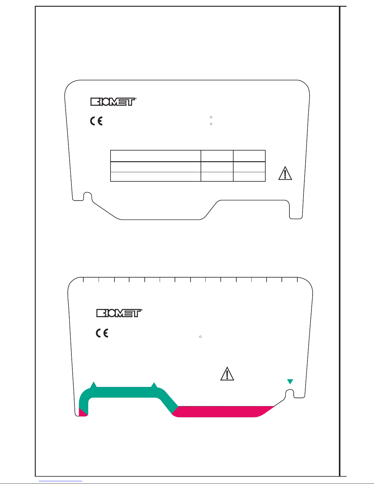
36
COIL TOLERANCES
FLEX SPAN
M
IN (9 cm)
MAX (13 cm)
M
AXIMUM DEPTH OF PENETRATION
MAXIMUM FRACTURE LENGTH
6.5 cm
7 cm
5.5 cm
6 cm
FLEXION GAUGE
FLEXIBLE TREATMENT COIL
FLX 1
R
FLX 1-2
R
FLEXION GAUGE
FLEXIBLE TREATMENT COIL
13 cm
9 cm
CABLE
102867-01 Rev. 10/09
0
1
2
3
4
5
6
7
8
9
10 11
12
13
14
CENTIMETERS
Parsippany, NJ 07054
FLEX RANGE
w
ww.biomet.com
0086
FLX 1
FLX 1-2
R
Parsippany, NJ 07054
www.biomet.com
0086
FLEX RANGE
Front View
Back View
Not to scale
Page 40
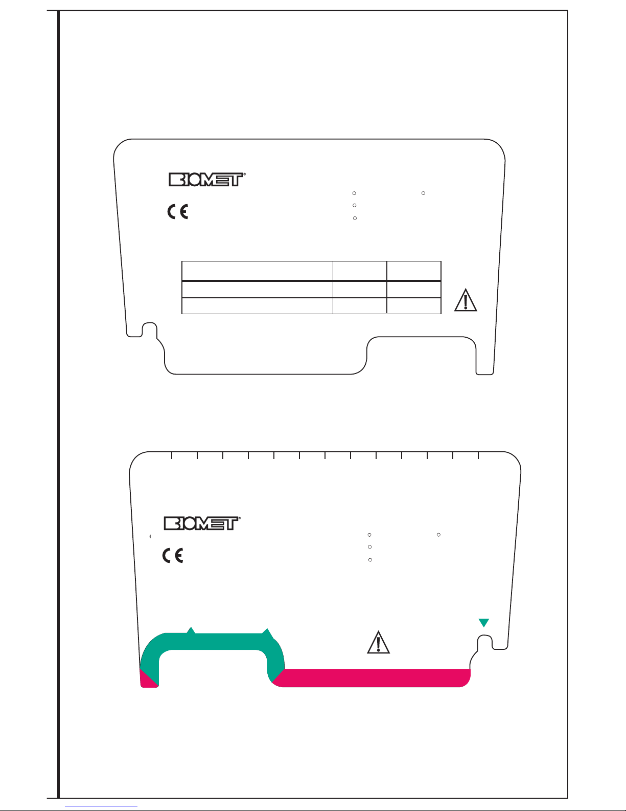
37
FLEXION GAUGE
FLEXIBLE TREATMENT COIL
FLX 2
R
FLX 2-2
R
FLX 2-4
R
FLX 2-5
R
COIL TOLERANCES
F
LEX SPAN MIN (8 cm)
MAX (11 cm)
MAXIMUM DEPTH OF PENETRATION
MAXIMUM FRACTURE LENGTH
8 cm
10 cm
7 cm
10 cm
102867-02 Rev. 10/09
CABLE
11 cm 8 cm
FLEXION GAUGE
FLEXIBLE TREATMENT COIL
FLX 2
R
FLX 2-2
R
FLX 2-4
R
FLX 2-5
R
CENTIMETERS
0
1
2
3
4
5
6
7
8
9
10
11
12
FLEX RANGE
Parsippany, NJ 07054
www.biomet.com
0086
Parsippany, NJ 07054
www.biomet.com
0086
Front View
Back View
Not to scale
Page 41
38
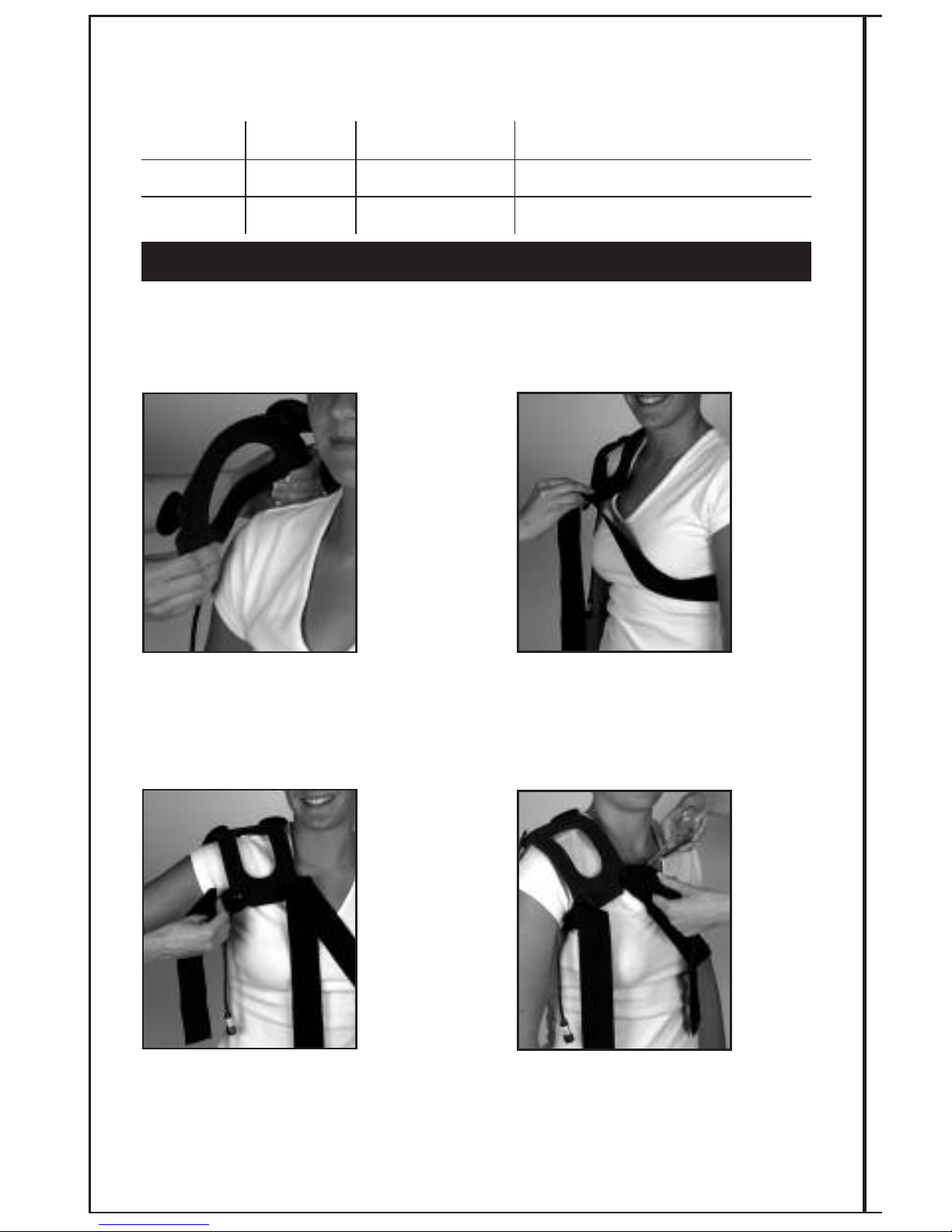
Coil Application Instructions
Applies to:
Assembly # Description Coil Replacement # Suggested Placement
5113 FLX
®
1-3 0103 Clavicle
5213 FLX
®
2-3 0203 Clavicle - Larger
See Flexion Gauge Instructions for measuring the tolerances of the coil on pages 40-41. Used
for right or left clavicle fracture applications.
NOTE: Coil comes pre-assembled for right clavicle applications only. For left clavicle
applications, unsnap the two straps on the pre-assembled coil and switch them.
Position coil on clavicle over fracture site,
according to physician instructions
(Position coil with cable toward waist).
Make sure coil is firmly in place before
securing straps.
Bring long strap diagonally across
the back and then around to the front
across the chest. Press strap onto
Velcro
®
hook. Dotted line represents
alternate placement of long strap.
Cut excess straps to size.
Short strap is then positioned under the
arm and brought around to the front.
Attach short strap to the coil by pressing
strap onto Velcro
®
hook. Readjust both
long and short straps for a secure,
comfortable fit (DO NOT over tighten).
12
3
FLX®1-3 OR 2-3 CLAVICLE APPLICATION
2
4
Page 42

39
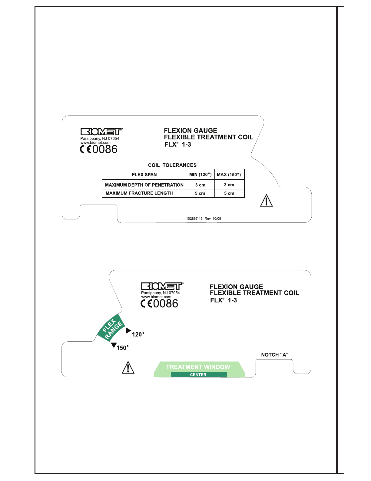
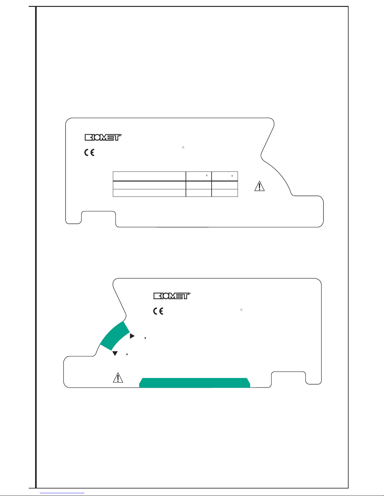
Flexion Gauge Instructions for FLX®1-3 & FLX®2-3 Coils
In order to ensure proper fit and efficacious treatment, the Flexion Gauge should be checked
for the proper shape.
1) Place the coil at the treatment site and shape for best fit. Coil should be bent only
in one direction. Do not kink or twist the coil.
2) Remove the shaped coil and place edge closest to the connector cable into the
slot/notch on the right hand side of the Flexion gauge marked with a green triangle.
Move the gauge through the open middle of the coil until the opposite coil edge
touches the gauge again. The coil edge should fall within the green zone in the area
marked “FLEX RANGE”. Each Flexion Gauge has a chart of coil tolerances with
depth of penetration data.
3) If the coil edge does not fall within the green zone, contact your Biomet
representative for a suitable replacement and assistance.
Refer to pages 40 and 41 for diagrams of these Flexion Gauges.
Page 43
40
Back View
Front View
Not to scale
Page 44
41
TREATMENT WINDOW
120
150
NOTCH "A"
F
L
E
X
R
A
N
G
E
0086
Parsippany, NJ 07054
www.biomet.com
FLEXION GAUGE
FLEXIBLE TREATMENT COIL
FLX 2-3
R
Front View
C
OIL TOLERANCES
FLEX SPAN
MIN (120 )
M
AX (150 )
MAXIMUM DEPTH OF PENETRATION
MAXIMUM FRACTURE LENGTH
4
cm
8 cm
4
cm
8 cm
1
02867-23 Rev. 10/09
FLEXION GAUGE
FLEXIBLE TREATMENT COIL
FLX 2-3
R
0086
Parsippany, NJ 07054
www.biomet.com
Back View
Not to scale
Page 45
42
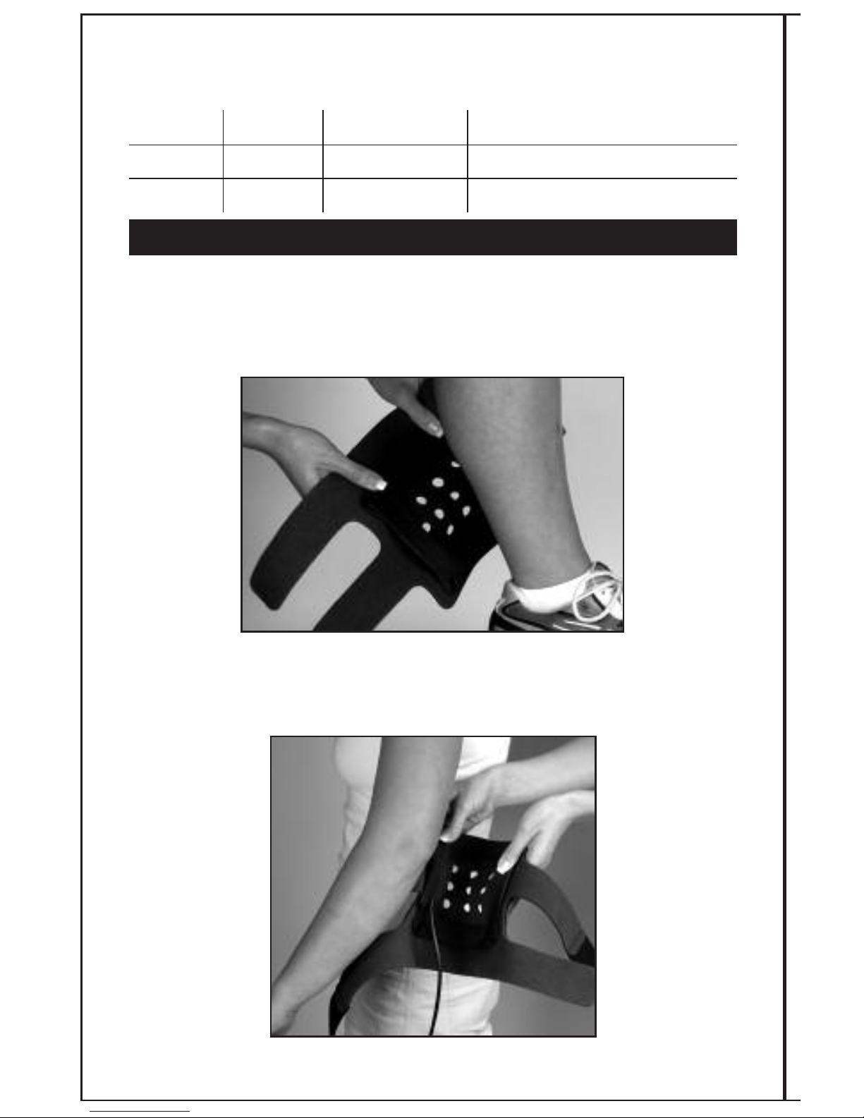
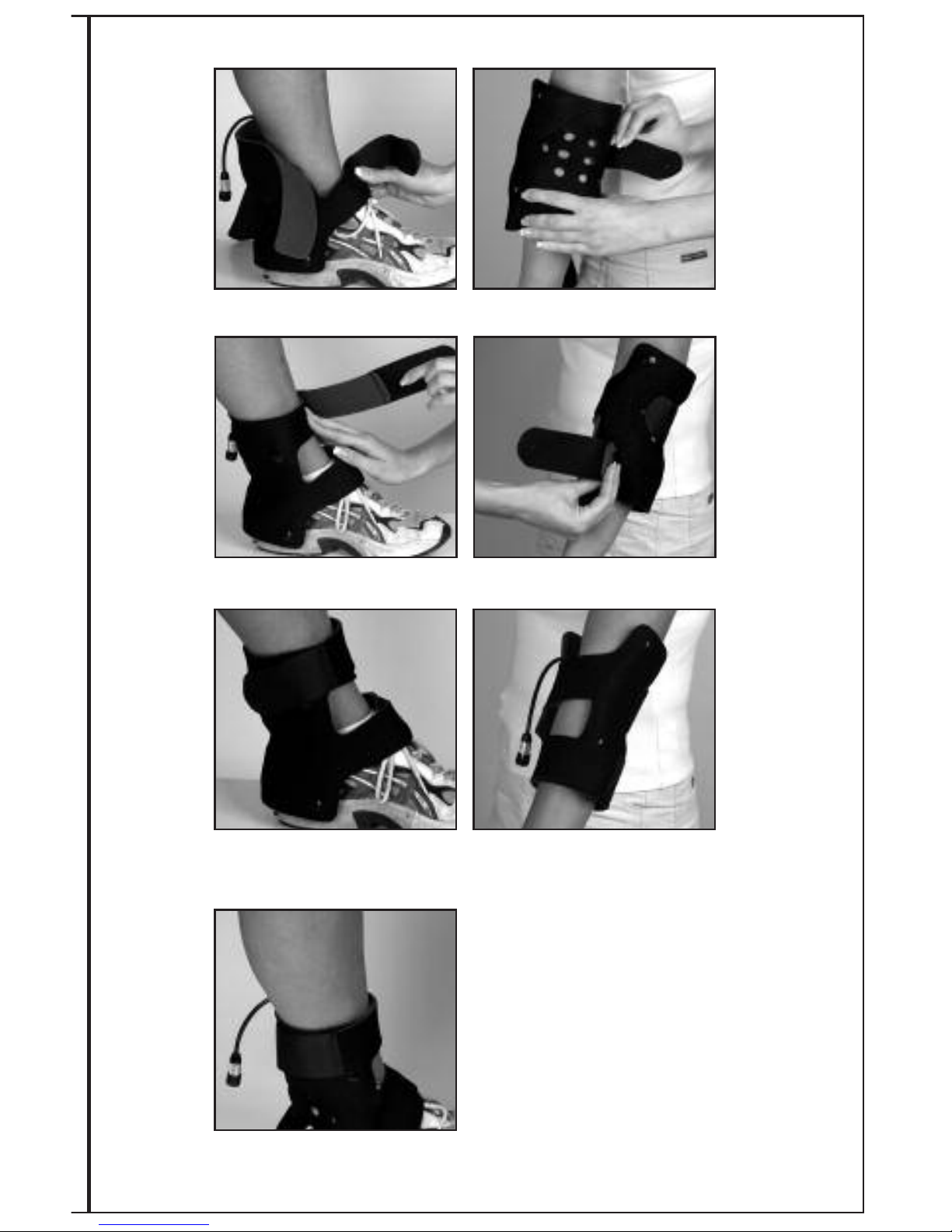
Coil Application Instructions for: FLX®2-4 and FLX®4-4 Coils
Applies to:
Assembly # Description Coil Replacement # Suggested Placement
5214 FLX
®
2-4 0204 Ankle
5414 FLX
®
4-4 0404 Ankle - Larger
See Flexion Gauge Instructions for measuring the tolerances of the coil on page 44.
Used for ankle/elbow fracture applications.
NOTE: Position coil with cable toward waist.
Make sure coil is firmly in place before securing straps.
Position coil over the fracture site at the back of the ankle (for ankle application) or over
the elbow (for elbow application), according to physician instructions. Make certain the coil
is flush with the bottom of the foot or centered over the elbow. Make sure coil is firmly in
place before securing straps.
1
FLX®2-4 AND 4-4 ANKLE/ELBOW APPLICATION
Page 46
43
Both top & bottom straps are then positioned over the front of the ankle or elbow.
2
Fasten straps into place by pressing strap onto Velcro®hook.
3
Readjust both straps for a secure, comfortable fit opposite the Velcro®hook before
cutting excess straps to size. DO NOT over tighten.
4
Optional (for ankle application only): If the coil
migrates upward, you may use the additional
strap provided to secure the coil. Simply fasten
one end of the strap to the medial (inside seam)
side of the ankle, bring strap under the foot and
back around to the lateral side (outside) side of
ankle. Fasten strap into place by pressing strap
onto Velcro
®
hook.
5
Page 47

44
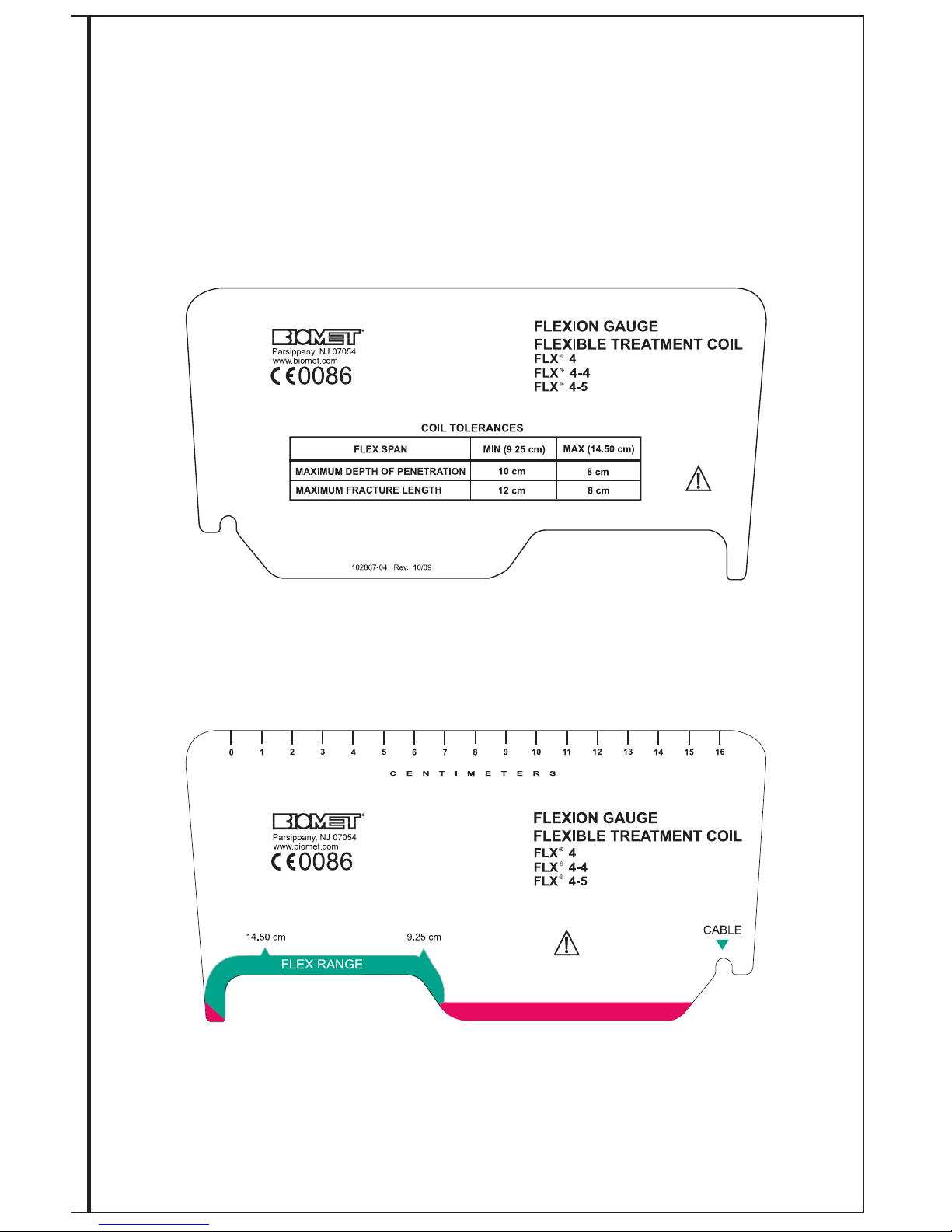
Flexion Gauge Instructions for FLX®2-4 & FLX®4-4 Coils
In order to ensure proper fit and efficacious treatment, the Flexion Gauge should be checked
for the proper shape.
1) Place the coil at the treatment site and shape for best fit. Coil should be bent only in
one direction. Do not kink or twist the coil.
2) Remove the shaped coil and place edge closest to the connector cable into the
slot/notch on the right hand side of the Flexion Gauge marked with a green triangle.
The opposite coil edge should fall within the green zone in the area marked
“FLEXION RANGE”. Each Flexion Gauge has a chart of coil tolerances with depth
of penetration data.
3) If the coil edge does not fall within the green zone, contact your Biomet
representative for a suitable replacement and assistance.
Refer to page 45 for a diagram of the FLX
®
4-4 Coil Flexion Gauge.
Refer to page 25 for a diagram of the FLX®2-4 Coil Flexion Gauge.
Page 48
45
Front View
Back View
Not to scale
Page 49
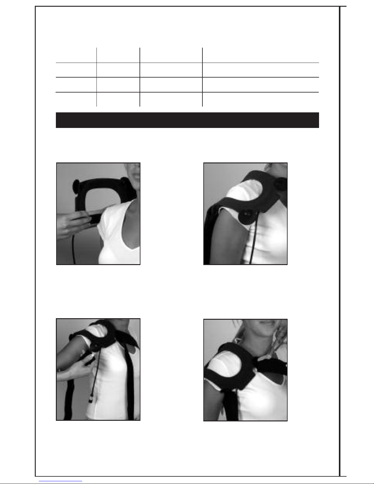
Coil Application Instructions For: FLX®2-5, 3-5, 4-5
Applies to:
Assembly # Description Coil Replacement # Suggested Placement
5215 FLX
®
2-5 0205 Humerus, Proximal - Small
5315 FLX
®
3-5 0305 Humerus, Proximal - Medium
5415 FLX
®
4-5 0405 Humerus, Proximal - Larger
See Flexion Gauge Instructions for measuring the tolerances of the coil on page 47.
Used for proximal humerus/shoulder applications.
Position coil over the proximal humerus
fracture site, according to physician
instructions (Position coil with cable
toward waist). Make sure coil is firmly
in place before securing straps.
Bring the long strap diagonally
across the back and then around to
the front across the chest. Press
strap onto Velcro
®
hook.
Readjust both straps for a secure,
comfortable fit. DO NOT over tighten
before cutting excess straps to size.
Second strap is then positioned under the
arm and brought around to the front.
Attach strap to the coil by pressing strap
onto Velcro
®
hook.
12
3
FLX®2-5 OR 3-5 OR 4-5 PROXIMAL HUMERUS/SHOULDER APPLICATION
2
4
46
Page 50

47
Flexion Gauge Instructions for FLX®2-5, FLX®3-5 & FLX®4-5 Coils
In order to ensure proper fit and efficacious treatment, the Flexion Gauge should be checked
for the proper shape.
1) Place the coil at the treatment site and shape for best fit. Coil should be bent only
in one direction. Do not kink or twist the coil.
2) Remove the shaped coil and place edge closest to the connector cable into the
slot/notch on the right hand side of the Flexion Gauge marked with a green triangle.
The opposite coil edge should fall within the green zone in the area marked
“FLEXION RANGE”. Each Flexion Gauge has a chart of coil tolerances with depth
of penetration data.
3) If the coil edge does not fall within the green zone, contact your Biomet
representative for a suitable replacement and assistance.
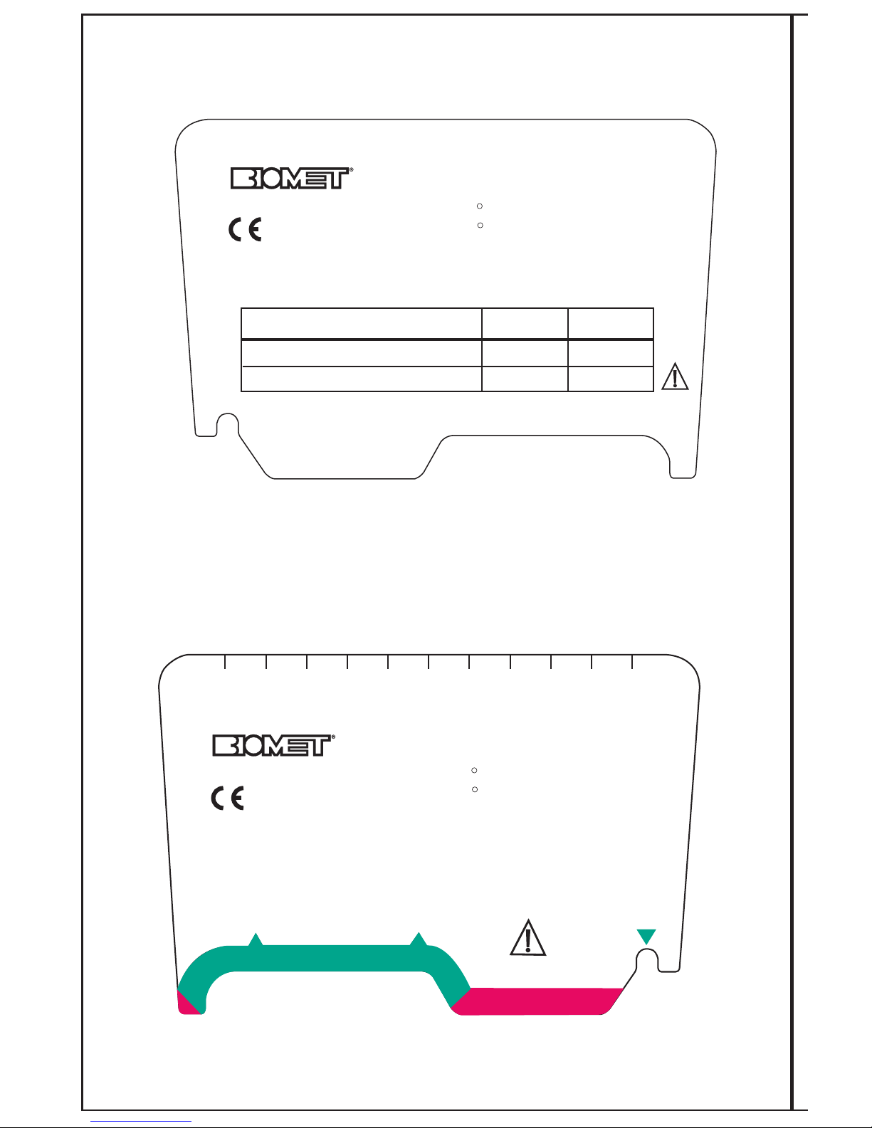
Refer to pages 37, 48 and 49 for Flexion Gauge diagrams.
Page 51
48
FLEXION GAUGE
FLEXIBLE TREATMENT COIL
FLX 3
R
FLX 3-5
R
COIL TOLERANCES
FLEX SPAN MIN (5 cm)
MAX (9 cm)
MAXIMUM DEPTH OF PENETRATION
MAXIMUM FRACTURE LENGTH
7 cm
7 cm
5.5 cm
6 cm
102867-03 Rev. 10/09
FLEXION GAUGE
FLEXIBLE TREATMENT COIL
FLX 3
R
FLX 3-5
R
CABLE
5 cm
9 cm
0
1
2
3
4
5
6
7
8
9
10
CENTIMETERS
FLEX RANGE
Parsippany, NJ 07054
www.biomet.com
0086
Parsippany, NJ 07054
www.biomet.com
0086
Front View
Back View
Not to scale
Page 52
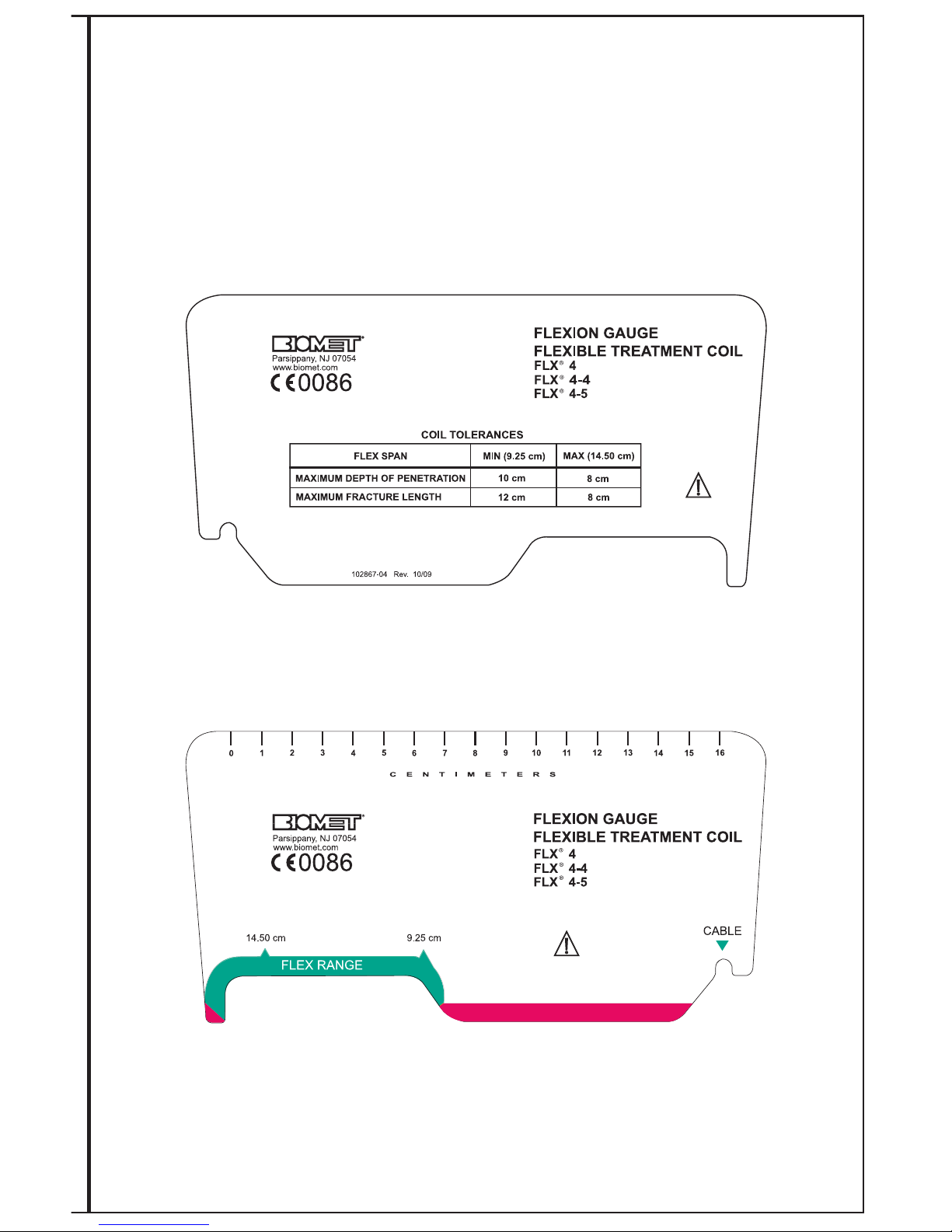
49
Front View
Back View
Not to scale
Page 53
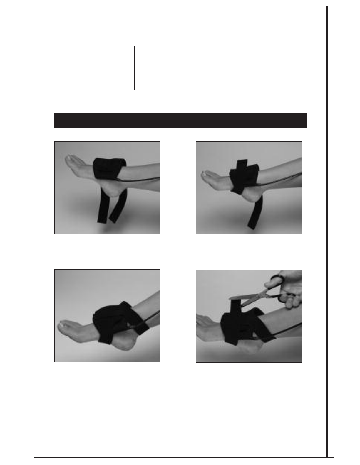
50
Coil Application Instructions For: FLX®- XL Coilette
Applies to:
Assembly # Description Coil Replacement # Suggested Placement
5620 FLX
®
- XL 5700 Foot/Ankle, Hand, Wrist
Coilette
Center the coil over the fracture site.
Conform the coil and verify with gauge.
Wrap lower strap around bottom of
foot and attach to Velcro
®
hook.
Adjust straps for comfort. Excess
strap length may be cut away. When
treatment is complete for the day,
remove the coilette by loosening
the straps.
Wrap upper strap around ankle and
cable. Attach to Velcro
®
hook.
12
3
ANKLE APPLICATION
2
4
Page 54
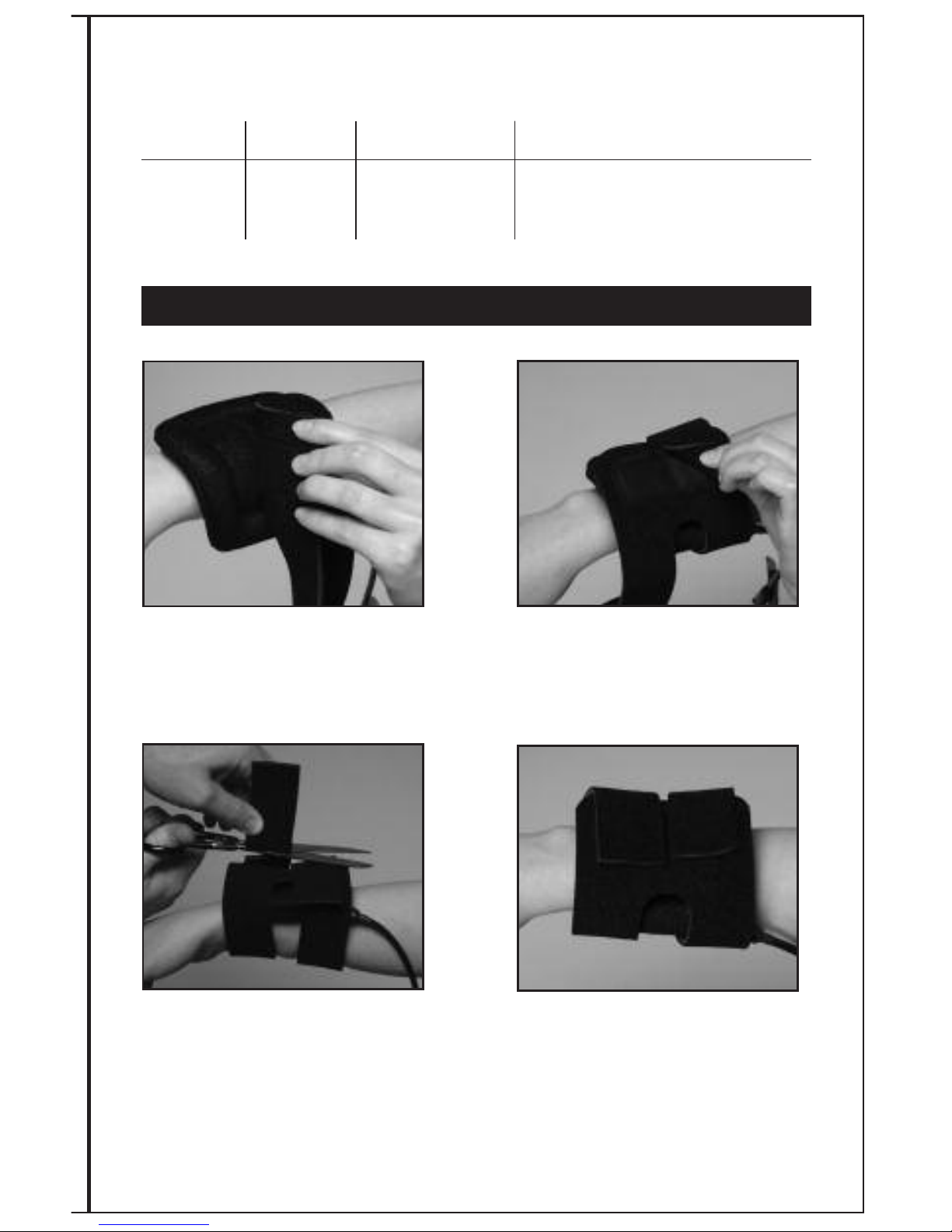
51
Coil Application Instructions For: FLX®- XL Coilette
Applies to:
Assembly # Description Coil Replacement # Suggested Placement
5620 FLX
®
- XL 5700 Foot/Ankle, Hand, Wrist
Coilette
Center the coilette over the fracture site.
Conform shape and remove. Verify coil is
conformed within treatment limit with
Flexion gauge.
Secure upper proximal strap first.
Wrap strap around hand and attach
to Velcro
®
hook.
Adjust straps for comfort. When
treatment is complete for the day,
remove the coilette by loosening
the straps.
Secure lower/distal strap by wrapping
around fracture site and attaching to
Velcro
®
hook. Cut away excess strap length.
12
3
WRIST APPLICATION
2
4
Page 55
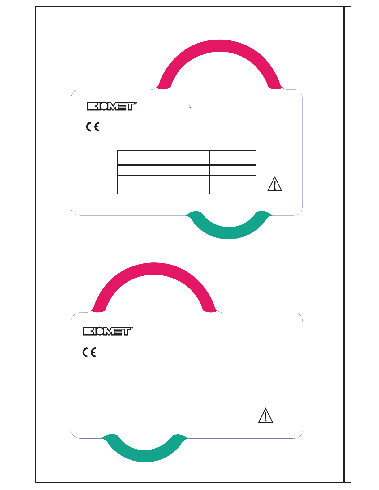
CURVE
CURVE
S
A
D
D
L
E
E
L
L
I
P
T
I
C
A
L
FLX Coilette
Shape
Depth of
Penetration
Vertical Fracture
Length
Flat
Elliptical
Saddle
3.5 cm
4.25 cm
5.5 cm
6 cm
6 cm
4 cm
COIL SPECIFICATIONS
106109 Rev. 10/09
TREATMENT XL COILETTE GAUGE
FLX FLEXIBLE
R
0086
Parsippany, NJ 07054
www.biomet.com
52
CURVE
CURVE
S
A
D
D
L
E
E
L
L
I
P
T
I
C
A
L
0086
Parsippany, NJ 07054
www.biomet.com
Front View
Back View
Not to scale
Page 56
53
Coil Application Instructions
Applies to:
Assembly # Description Coil Replacement # Suggested Placement
5613 FLX
®
- 0603 Clavicle
Coilette
Clavicle
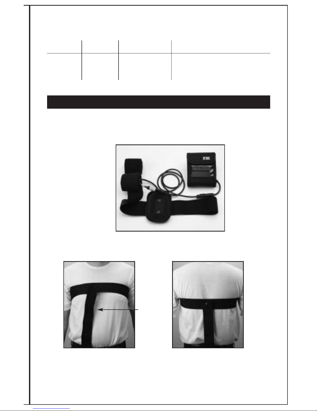
Place the coilette and straps provided on a flat surface. The straps are provided snapped
together. Notice that the strap with Velcro®is longer than the one without Velcro®.
b) Note: The snap should be located
in the center of your back.
a) Wrap the long strap with Velcro
®
around your chest and back onto itself.
Secure it in place with the Velcro
®
Excess
cable strap
1
2
CLAVICLE PLACEMENT APPLICATION INSTRUCTIONS
See Conforming the Coil and Flexion gauge instructions on page 55.
Components: The FLX®Coilette Clavicle comes with a FLX®Coilette and straps to be fitted over
the effected torso and shoulder.
Page 57
54
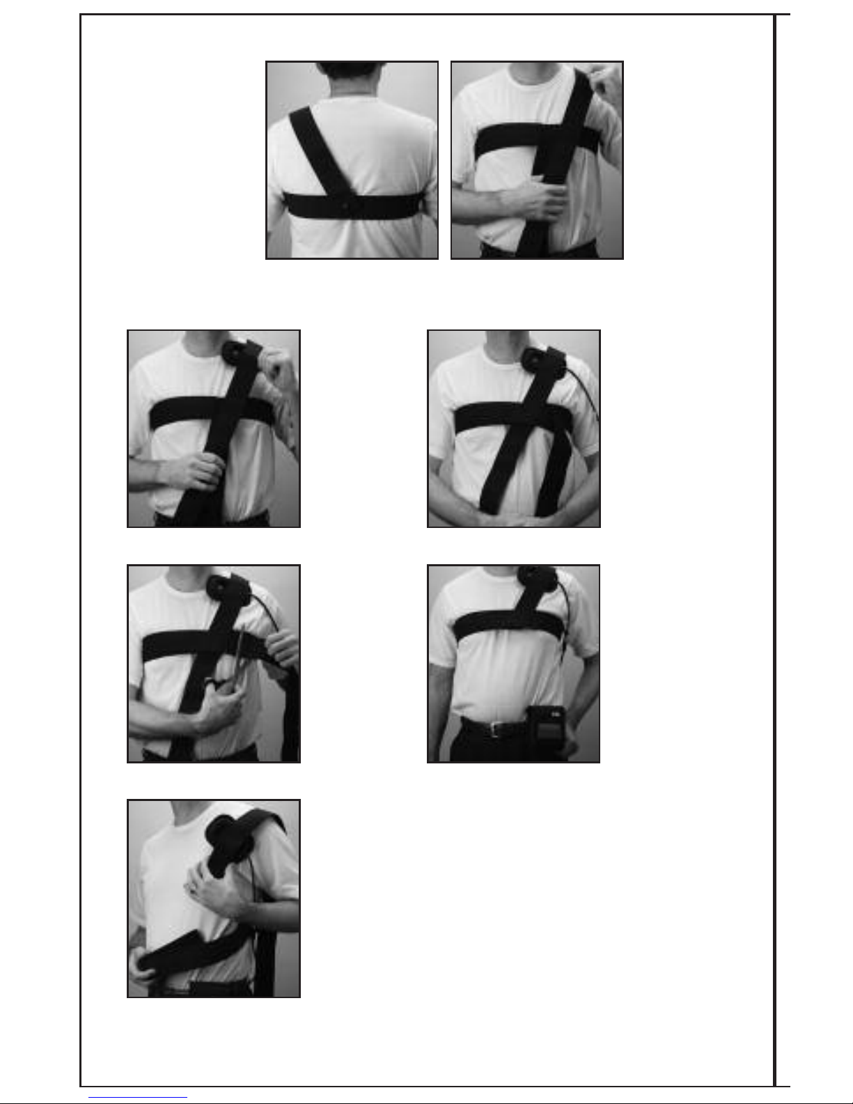
Pull the remaining short strap from behind your back over the shoulder on the
treatment side.
3
Place the FLX®Coilette over the
treatment site
as instructed by
your physician
or Biomet
representative.
Secure the
Coilette in place
by passing the
strap over the
Velcro
®
on the
Coilette and
onto the chest
strap. Close the
chest strap.
4
5
a) Adjust for
comfort. Excess
shoulder and
chest strap
lengths may be
then cut away.
b) Common
position.
6a
When treatment is completed for the day, remove the coil by
unhooking the strap from around your chest. Leave the strap
over your shoulder secured to the coil and chest strap.
Remove the coil. It is ready for your next daily treatment.
7
6b
Page 58

55
Flexion Gauge Instructions for FLX®Flexible Treatment Coilette -Clavicle
In order to ensure proper fit and efficacious treatment, the Flexion Gauge should be checked
for the proper shape.
1) Place the coil at the treatment site and shape for best fit. The FLX®Coil must only
be bent in one of two directions (Long or short axis, see illustrations that follow).
Do not kink or twist the coil. The shape of the coil will determine the specifications.
2) Remove the shaped coil and utilize the Flexion Gauge to verify the acceptable bend
according to the shape listed below.
3) If the coil edge does not fall within the green zone, contact your Biomet
representative for a suitable replacement and assistance.
Optional Shapes
Flat – Flexion Gauge not required
Elliptical – Place treatment coil over green portion of Flexion Gauge. The treatment coil bend
should not exceed the curve indicated on this Gauge.
Saddle – Place the treatment coil over the red portion of the Flexion Gauge. The coil bend
should not exceed the curve indicated on this Flexion Gauge.
Refer to page 63 for a diagram of the Flexion Gauge.
Page 59
Flexion Gauge Instructions for FLX®-Mini Coil
In order to ensure proper fit and efficacious treatment, the Flexion Gauge should be checked
for the proper shape.
1) Place the coil at the treatment site and shape for best fit. Treatment coil should be
bent only in one direction. Do not kink or twist the coil.
2) Remove the shaped treatment coil and place edge closest to the connector cable into
the slot/notch on the right hand side of the Flexion Gauge marked with a green
triangle. The opposite treatment coil edge should fall within the green zone in the
area marked “FLEX RANGE”. Each Flexion Gauge has a chart of coil tolerances with
depth of penetration data.
3) If the treatment coil edge does not fall within the green zone, contact your Biomet
representative for a suitable replacement and assistance.
Refer to page 58 for a diagram of the Flexion Gauge.
56
Coil Application Instructions for the: FLX®-Mini
Applies to:
Assembly # Description Coil Replacement # Suggested Placement
5630 FLX
®
-Mini 5650 Phalanges
Page 60
57
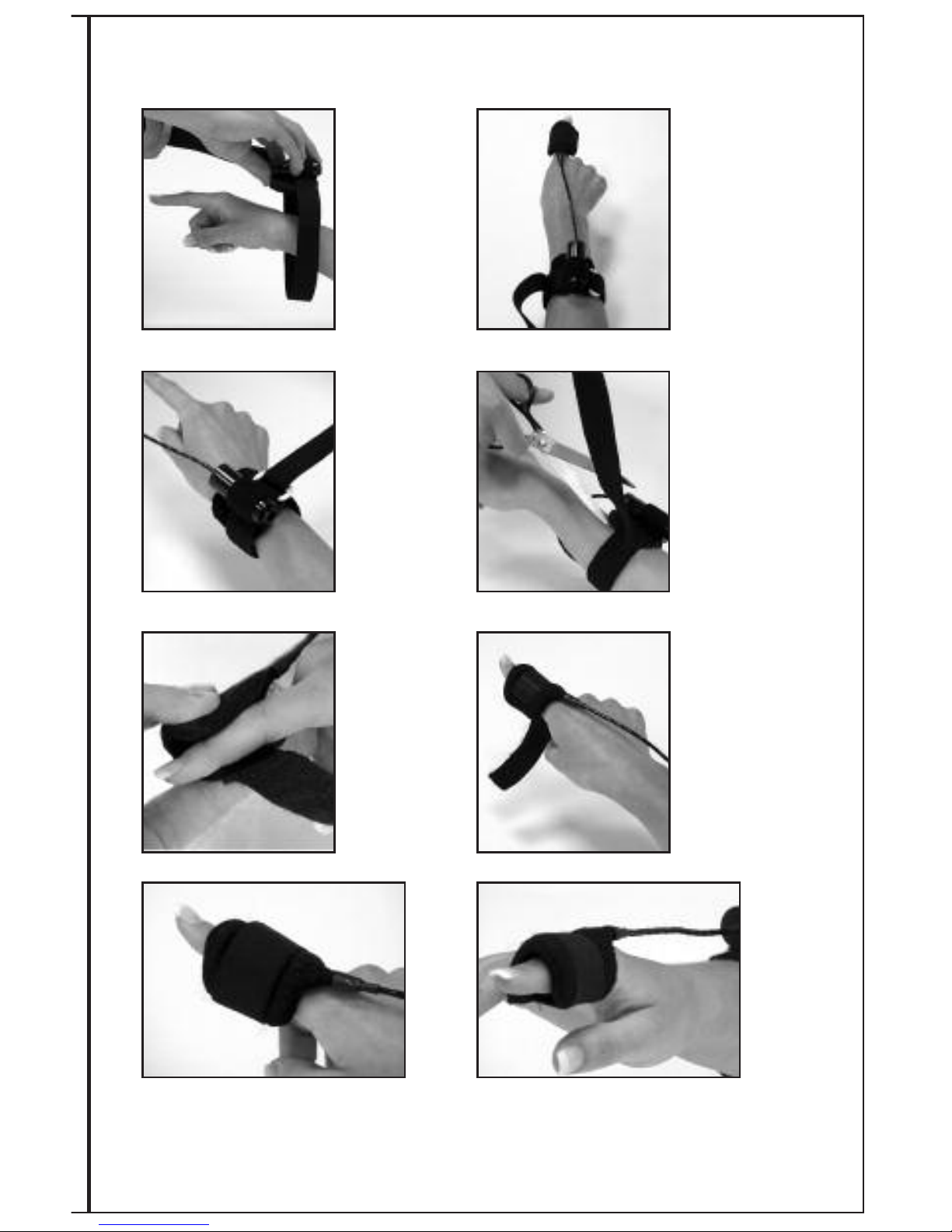
EBI Bone Healing System®FLX®-Mini Coilette Instructions
Slip wrist
connector strap
around wrist.
Adjust strap up
or down arm
until length
of wire to FLX
®
Mini Coilette is
properly placed.
1
2
Feeding strap
through ring,
adjust and tighten securing
strap to Velcro
®
hook.
b) Trim excess
strap with
scissors.
3
4
Adjust FLX®-Mini
Coilette to size by
squeezing or
opening.
Secure FLX
®
-Mini
Coilette in place
by wrapping strap
around finger and
securing onto
Velcro
®
hook.
5
6
Trim excess strap with scissors.
Warning! Do not place FLX
®
-Mini
Coilette over metallic splints or jewelry.
Connect EBI Bone Healing System
®
Stimulator link cable to wrist connector by
inserting plug into jack. Begin treatment.
7
8
Page 61
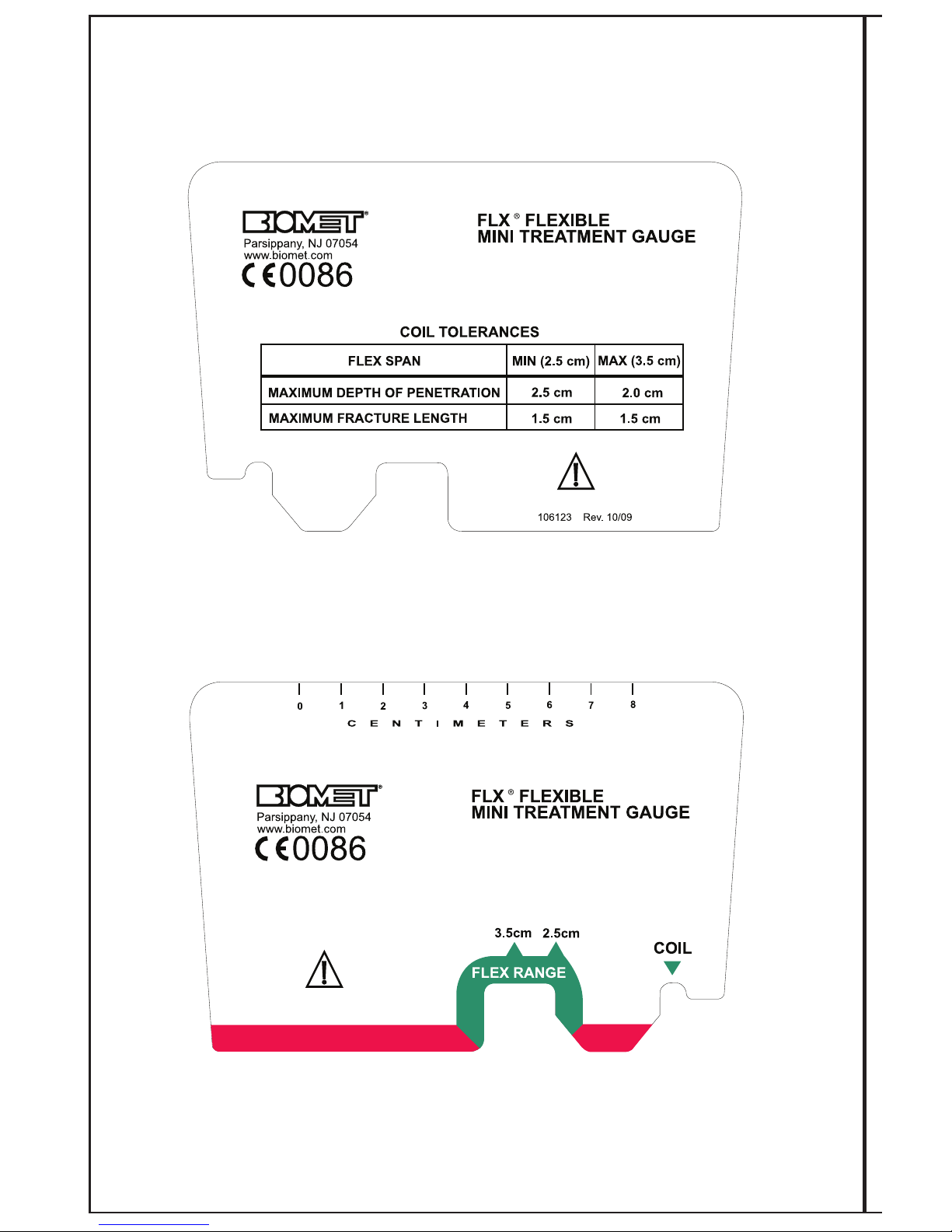
58
Front View
Back View
Not to scale
Page 62
Flexion Gauge Instructions for FLX®Standard Coilette
In order to ensure proper fit and efficacious treatment, the Flexion Gauge should be checked
for the proper shape.
1) Place the treatment coil at the treatment site and shape for best fit. The treatment
coil must only be bent in one of two directions (Long or short axis, see illustrations
that follow). Do not kink or twist the treatment coil. The shape of the treatment coil
will determine the specifications.
2) Remove the shaped treatment coil and utilize the Flexion Gauge to verify the
acceptable bend according to the shape listed below.
3) If the treatment coil edge does not fall within the green zone, contact your Biomet
representative for a suitable replacement and assistance.
Optional Shapes
Flat - Flexion Gauge not required
Elliptical - Place treatment coil over green portion of Flexion Gauge. The coil bend should not
exceed the curve indicated on this Flexion Gauge.
Saddle - Place the treatment coil over the red portion of the Flexion Gauge. The coil bend
should not exceed the curve indicated on this Flexion Gauge.
59
Coil Application Instructions for the: FLX®-Standard Coilette
Applies to:
Assembly # Description Coil Replacement # Suggested Placement
5610 Standard 0600 Metatarsals, Scaphoid, Distal Radius,
Coilette Cuboid, M-L Malleous
Page 63
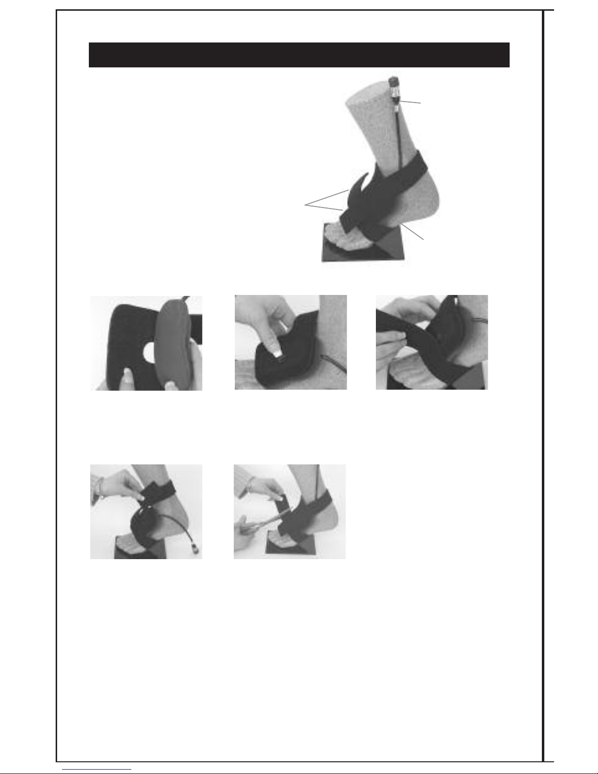
60
Foot Application
For System Assembly #5610
and Coilette #0600
Attach the FLX®-Standard
Coilette to the strap by
connecting it to the Velcro
®
hook provided on the strap.
Center the FLX
®
-Standard
Coilette over the fracture site.
Wrap lower strap around
bottom of foot and attach
to Velcro
®
hook.
Wrap top strap around ankle
and cable and attach to
Velcro
®
hook.
Adjust strap for comfort.
Excess strap length may then be cut away.
When treatment is completed for the day,
remove the FLX
®
-Standard Coilette by
loosening the straps. Leave the straps
attached to the Coilette. It is ready for your
next daily treatment.
Dual Velcro
®
Straps with
snap
Cable
FLX
®
Coilette
1
23
4
5
FLX®-STANDARD COILETTE FLEXIBLE TREATMENT COIL
Page 64
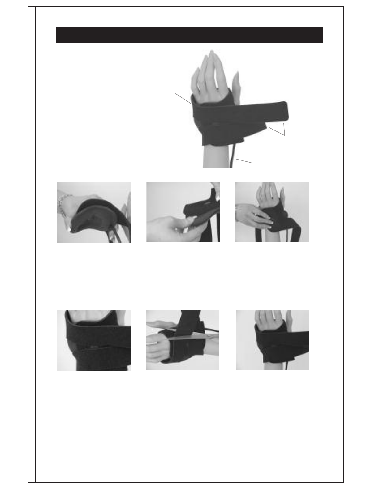
Hand Application
For System Assembly #5610
and Coilette #0600
Shape and place the
FLX
®
-Standard Coilette
over the treatment site
as instructed by your
physician or Biomet
representative.
Place the
FLX
®
-Standard
Coilette onto the
Velcro
®
hook on the strap.
Place the FLX
®
-Standard
Coilette over treatment
site and bring straps
around each side of
thumb.
Secure
Velcro
®
straps
onto the Velcro®hook.
Adjust for comfort.
Excess strap length may
then be cut away.
When treatment is
completed for the day,
remove the FLX
®
-Standard
Coilette by loosening the
straps. Leave the straps
attached to the FLX
®
Standard Coilette. It is ready
for your next daily treatment.
Dual Velcro
®
Straps with
Velcro
®
hooks
Cable
FLX
®
Coilette
61
FLX®-STANDARD COILETTE FLEXIBLE TREATMENT COIL
1
23
4
5
6
Page 65
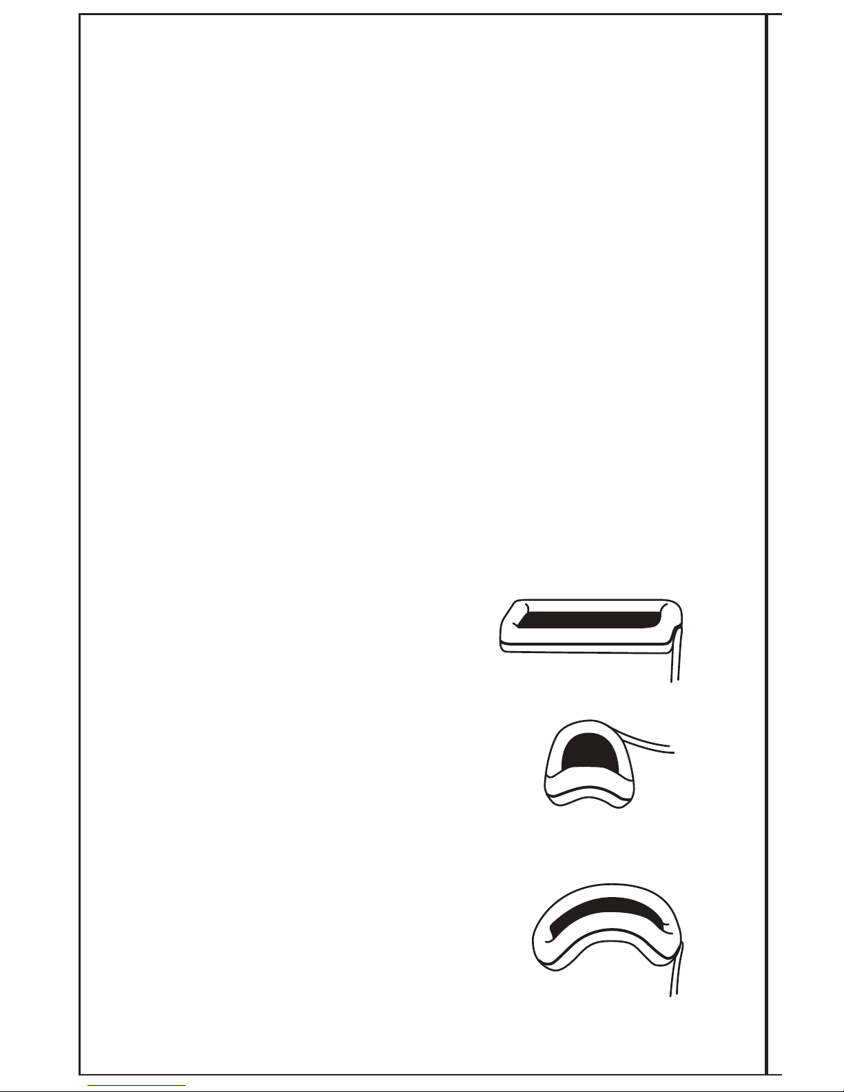
62
Biomet
®
FLX®Flexible Treatment Coilette
Specifications and Gauge Directions
FLX®Coilette Shape Depth of Penetration Vertical Fracture Length
Flat 2.75 cm 4 cm
Elliptical 3.5 cm 4 cm
Saddle 3.5 cm 2 cm
To insure efficacious treatment with the FLX®Coilette Coil:
1. Place the Coilette on the treatment site and shape for best fit.
The Coilette must only be bent in one of two directions (long axis
or short axis, see illustrations). Do not kink or twist the Coilette.
2. The shape of the Coilette will determine the coil specifications
(see above).
3. Remove the Coilette and utilize the enclosed FLX®Coilette Gauge
to verify the shape listed below.
Optional Shapes:
Flat Shape (see coil specifications above)
The FLX®Coilette Gauge is not needed.
Elliptical Shape (see coil specifications above)
Place the Coilette over the green portion of the
gauge marked “elliptical”. The Coilette bend
should not exceed the elliptical curve indicated
on the FLX®Coilette Gauge.
Saddle Shape (see specifications above)
Place the Coilette over the red portion of the
gauge marked “saddle”. The Coilette bend
should not exceed the saddle curve on the
FLX®Coilette Gauge.
Page 66
63
F
LX Coilette
Shape
Depth of
P
enetration
Vertical Fracture
Length
Flat
Elliptical
Saddle
2
.75 cm
3.5 cm
3.5 cm
4
cm
4 cm
2 cm
COIL SPECIFICATIONS
CURVE
CURVE
CURVE
CURVE
1
02266.C00 Rev. 10/09
S
A
D
D
L
E
E
L
L
I
P
T
I
C
A
L
E
L
L
I
P
T
I
C
A
L
FLEXIBLE TREATMENT COIL
FLEXION GAUGE
FLEXIBLE TREATMENT COIL
COILETTE
S
A
D
D
L
E
0086
Parsippany, NJ 07054
www.biomet.com
0086
Parsippany, NJ 07054
www.biomet.com
FLEXION GAUGE
COILETTE
Front View
Back View
Not to scale
Page 67

64
CLEANING INSTRUCTIONS
THE 2001 SYSTEM
The controller and charger can be cleaned by wiping with a damp cloth and mild soap. Do
not immerse in water or use solvents or other cleaning agents. Do not machine dry.
FLX
®
COILS
FLX
®
coils are not sterile. Clean with mild soap and water by wiping with a damp cloth. Do
not immerse in water or any liquid.
TREATMENT COMPLETION
Treatment should not be suspended until healing occurs or your physician recommends that you
discontinue use of the device. The device is programmed to deliver 400 consecutive days of
treatment.
The maximum recommended treatment period is 9 months. See “SYSTEM ENDPOINT 400
DAYS” (Page 17).
RETURNING DEFECTIVE PRODUCT
A Stimulator Control Unit, AC Adapter, Flexible Treatment Coil, or Link Cable that is defective may
be returned to Biomet. To return a part, or if you are having difficulty with the operation of your
EBI Bone Healing System
®
Stimulator, please contact the Quality Assurance Department:
1-973-299-9300 (follow prompts to Product Support)
NOTE: Only defective units may be returned to Biomet. Units that have passed through their
system endpoints or that have previously delivered a complete prescribed treatment must be
disposed of properly (see Disposal Instructions).
DISPOSAL INSTRUCTIONS
The Stimulator control unit, AC adapter, link cables, FLX®Treatment Coil, cradle and battery are
regulated and should be properly disposed of or recycled according to local statutes and
regulations. Please contact your local recycling center for instructions and procedures to safely
dispose of the EBI Bone Healing System
®
Stimulator.
Page 68
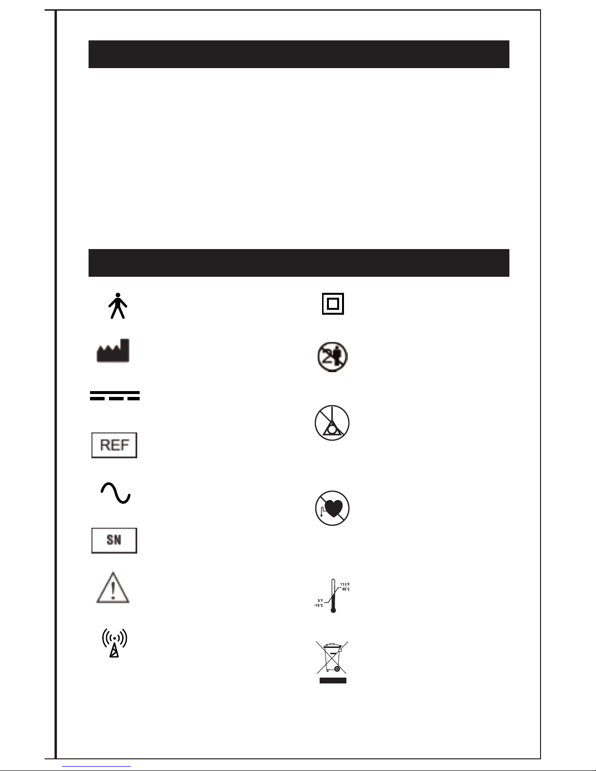
65
EQUIPMENT CLASSIFICATION
• Models 2001, 2001A, 2001J, 2001U
Class I
Type B
• Models 2001E
Class II
Type B
• Ordinary equipment without protection against ingress of water
• Equipment not suitable for use in presence of flammable anaesthetic
mixture with air or with oxygen or with nitrous oxide
• Mode of operation – continuous
SYMBOL DESCRIPTION
Type B
Manufacturer
Direct Current
Catalog Number
Alternating Current
Serial Number
Attention - See Instructions
Non-ionizing Radiation
Class II
Single Patient Use/
Prescription Only
Not for use by patients who
are pregnant or becoming
pregnant
Not recommended for
patients with certain types
of pacemakers or implantable
defibrillators
Transportation and storage
temperature range
WEEE - Do not discard with
household waste
Page 69

66
REFERENCES
C.A.L. Bassett, Robert J. Pawluk, and A.A. Pilla. “Augmentation and Bone Repair by
Inductively Coupled Electromagnetic Fields”. Science 184:575-577, 1974.
C.A.L. Bassett, S.N. Mitchell, L. Norton, N. Caulo and S.R. Gaston. “Electromagnetic
Repairs of Non-Unions. Electrical and Magnetic Control of Musculoskeletal Growth and
Repair”. C.T. Brighton, ed., Grune and Stratton,
New York, 1979.
C.A.L. Bassett, S.N. Mitchell, and S.R. Gaston. “Treatment of Ununited Tibial Diaphyseal
Fractures With Pulsing Electromagnetic Fields”. Journal of Bone and Joint Surgery Vol. 63A, No. 4, pp. 511-523, April, 1981.
C.A.L. Bassett, S.N. Mitchell, and S.R. Gaston. “Pulsing Electromagnetic Field Treatment in
Ununited Fractures and Failed Arthodeses”. Journal of the American Medical Association
Vol. 247, No. 5, pp. 623-628, February 5, 1982.
C.A.L. Bassett, Pulsing Electromagnetic Fields: “A New Method to Modify Cell Behavior in
Calcified and Non-Calcified Tissue”. Calcified Tissue, Int. Vol. 34,
No. 1:1-8, 1982.
ORDERING INFORMATION
To order replacement coils or related components simply contact your Biomet representative
or call the Biomet Patient Support Department directly at 1-800-526-2579, 8:30 a.m. to 6:30
p.m. Eastern Time Monday through Friday. Outside the United States contact
your local EBI/Biomet Distributor, or call 1-973-299-9300.
The following information is necessary to expedite any requests:
• Patient name
• Physician name
• Where to send replacement items (patient home, MD office, etc.)
• Available component parts (See following page)
Page 70

67
Model 2001 BHS Replacement components
Applies to:
Description Part Number
Coil - FLX
®
1 0100
Coil - FLX
®
1-1 0101
Coil - FLX
®
1-2 0102
Coil - FLX
®
1-3 0103
Coil - FLX
®
2 0200
Coil - FLX
®
2-1 0201
Coil - FLX
®
2-2 0202
Coil - FLX
®
2-3 0203
Coil - FLX
®
2-4 0204
Coil - FLX
®
2-5 0205
Coil - FLX
®
3 0300
Coil - FLX
®
3-5 0305
Coil - FLX
®
4 0400
Coil - FLX
®
4-1 0401
Coil - FLX
®
4-4 0404
Coil - FLX
®
4-5 0405
Coil - FLX
®
5 5500
Coil - Standard Coilette 0600
Coil - Clavicle Coilette 0603
Coil - Mini-Coilette 5650
Coil - XL 5700
Controller 1067223-00
Charging Cradle 1067223-01
Page 71
ELECTROMAGNETIC COMPATIBILITY
• The use of accessories and cables other than those supplied may result in
increased emissions or decreased immunity of the equipment or system
• This equipment should not be used adjacent to or stacked upon other equipment
• Portable and mobile RF communications equipment can adversely affect the
operation of Medical Electrical Equipment
• In the event this equipment interferes with the operation of other equipment, or
experiences interference from other equipment, to continue treatment it will be
necessary to move the Model 2001 Bone Healing System away from the source of
the interference as indicated in table 4
Guidance and manufacturer’s declaration -
electromagnetic emissions
The Model 2001 Bone Healing System is intended for use in the electromagnetic
environment specified below. The customer or the user of the Model 2001 Bone Healing System
should assure that it is used in such an environment.
Emissions test
Compliance
Electromagnetic environment - guidance
RF emissions
CISPR 11
Group 2
The Model 2001 Bone Healing System must
emit electromagnetic energy in order to
perform its intended function. Nearby
electronic equipment may be affected.
RF emissions
CISPR 11
Class B
The Model 2001 Bone Healing System is
suitable for use in all establishments,
including domestic establishments and
those directly connected to the public
low-voltage power supply network that
supplies buildings used for domestic
purposes.
Harmonic emissions
IEC 61000-3-2
Not applicable
Voltage fluctuations/
flicker emissions
IEC 61000-3-3
Not applicable
Table 1
68
Page 72
The Model 2001 Bone Healing System is intended for use in the electromagnetic environment specified
below. The customer or the user of the Model 2001 Bone Healing System should assure that it is used
in such an environment.
Immunity test
Electrostatic
discharge (ESD)
IEC 610004-2
IEC 60601 test level Compliance level
Electromagnetic environment guidance
± 6 kV contact
± 8 kV air
Electrical fast
transient/burst
IEC 61000-4-4
Floors should be wood, concrete or
ceramic tile. If floors are covered
with synthetic material, the relative
humidity should be at least 30%.
± 2 kV for power
supply lines
± 1 kV for
input/output lines
Mains power quality should be that of
a typical commercial or hospital
environment.
Surge
IEC 61000-4-5
± 1 kV for
differential mode
± 2 kV for common
mode
Mains power quality should be that of
a typical commercial or hospital
environment.
Mains power quality should be that of
a typical commercial or hospital
environment. If the user of the Model
2001 Bone Healing System requires
continued operation during power
mains interruptions, it is
recommended that the Model 2001
Bone Healing System be powered
from an uninterruptible power supply
(UPS).
Voltage dips,
short
interruptions and
voltage variations on
power supply
input lines
IEC 61000-4-11
< 5% U
T
( > 95% dip in UT)
for 0.5 cycle
40% U
T
( 60% dip in UT)
for 5 cycles
70% U
T
( 30% dip in UT)
for 25 cycles
< 5% U
T
(> 95% dip in UT) for
5 sec
Power frequency
( 50/60 Hz )
magnetic field
IEC 61000-4-8
3 A/m
Power frequency magnetic fields should
be at levels characteristic of a typical
location in a typical commercial or
hospital environment.
Table 2
69
Guidance and manufacturer’s
declaration - electromagnetic immunity
Page 73
Immunity test
1 Vrms
1 V/m
Conducted RF
IEC 61000-4-6
Radiated RF
IEC 61000-4-3
3 Vrms
3 V/m
80 MHz to 2.5
GHz
NOTE 1. At 80 MHz and 800 MHz, the higher frequency applies.
NOTE 2. These guidelines may not apply in all situations. Electromagnetic propagation is affected by
absorption and reflection from structures, objects, and people.
Table 3
70
Guidance and manufacturer’s declaration -
electromagnetic immunity
The Model 2001 Bone Healing System is intended for use in the electromagnetic environment specified
below. The customer or the user of the Model 2001 Bone Healing System should assure that it is used
in such an environment.
Compliance
level
Electromagnetic environment guidance
Portable and mobile RF communications equipment should be used no closer to any part of the
Model 2001 Bone Healing System, including
cables, than the recommended separation distance calculated from the equation applicable to
the frequency of the transmitter.
Recommended separation distance
d = 3.5 √ P
d = 3.5 √ P 80 MHz to 800 MHz
d = 7 √ P 800 MHz to 2.5 GHz
where P is the maximum power output rating of
the transmitter in watts (W) according to the
transmitter manufacturer and d is the recommended separation distance in meters (m).
Field strengths from fixed RF transmitters, as
determined by an electromagnetic site survey,
should be less than the compliance level in each
frequency range.
Interference may occur in the vicinity of equipment marked with the following symbol:
IEC 60601
test level
a Field strengths from fixed transmitters, such as base stations for radio (cellular/cordless) telephones
and land mobile radios, amateur radio, AM and FM radio broadcast and TV broadcast cannot be predicted theoretically with accuracy. To assess the electromagnetic environment due to fixed RF transmitters,
an electromagnetic site survey should be considered. If the measured field strength in the location in
which the Model 2001 Bone Healing System is used exceeds the applicable RF compliance level, the
Model 2001 Bone Healing System should be observed to verify normal operation. If abnormal performance is observed, additional measures may be necessary, such as reorienting or relocating the Model
2001 Bone Healing System.
b Over the frequency range 150 kHz to 80 MHz, field strengths should be less than 1 V/m.
Page 74
Rated maximum
output power
of transmitter
W
Separation distance (meters) according to frequency of transmitter
150 kHz to 80 MHz
d = 3.5 √ P
80 MHz to 800 MHz
d = 3.5 √ P
800 MHz to 2.5 GHz
d = 7 √ P
.01 .35 .35 .7
.1
1.1
1.1
2.21
1
3.5
3.5 7
10 11.06
11.06
22.13
100
35 35
70
For transmitters rated at a maximum output power not listed above, the recommended separation
distance (d) in meters (m) can be estimated using the equation applicable to the frequency of the
transmitter, where P is the maximum output power rating of the transmitter in watts (W) according
to the transmitter manufacturer.
NOTE 1. At 80 MHz and 800 MHz, the separation distance for the higher frequency applies.
NOTE 2. These guidelines may not apply in all situations. Electromagnetic propagation is affected
by absorption and reflection from structures, objects, and people.
Table 4
71
Recommended separation distances between portable and
mobile RF communications equipment and the Model 2001 Bone
Healing System
The Model 2001 Bone Healing System is intended for use in an electromagnetic environment in which radiated RF disturbances are controlled. The customer or the user of the Model 2001 Bone Healing System
can help prevent electromagnetic interference by maintaining a minimum distance between portable and
mobile communications equipment (transmitters) and the Model 2001 Bone Healing System as recommended below, according to the maximum power output of the communications equipment.
Page 75

72
This section has been prepared to answer some of the questions most frequently asked about
the EBI Bone Healing System
Stimulator. If you have any further questions after reading it,
please contact your doctor or call Biomet’s Patient Support Department at 1-800-526-2579
8:30 a.m. – 6:30 p.m. Eastern Time Monday through Friday. Outside the United States contact
your local EBI/Biomet Distributor, or call 1-973-299-9300.
Bone is one of the tissues of the human body with the ability to mend itself when injured, in
much the same way as skin and other tissues can. After a break, bone repair processes
usually assure a sound union within a few months. Occasionally, however, the formation of
new bone is slow and the break fails to heal properly. Medically, prescribed use of the EBI
Bone Healing System
Stimulator, by a physician, can often promote healthy bone growth and
repair in cases when normal healing does not appear satisfactory.
Some commonly asked questions about the EBI Bone Healing System
®
Stimulator
1. Question: What is the EBI Bone Healing System
Stimulator and how does it promote
healing?
Answer: The EBI Bone Healing System
Stimulator is an effective method for promoting the
healing of fractures that have not mended spontaneously. The system consists of a
treatment coil, which is incorporated into a cast, on top of a cast or brace, or placed directly
on to the skin. The control unit delivers a therapeutic electric current to the treatment coil at
the fracture site. Many events occur at the time of fracture to promote healing. Among
them are your body’s own natural electrical currents. However, if these natural electrical
currents are interrupted, healing may become problematic. The therapeutic electrical current
produced by the EBI Bone Healing System
Stimulator is very similar to the currents that the
body produces naturally to signal the bone to begin healing in the first few weeks after your
fracture. Just as you are unaware of the electrical currents produced by your own body, you
may not be aware of the therapeutic electrical current produced by the EBI Bone Healing
System
Stimulator.
2. Question: Is the system safe?
Answer: The system has been widely used because of its proven success and absence of
any known risks. It does not require surgery, has no known side effects, and is effective
even in fractures where internal fixation devices such as rods or pins already exist.
3. Question: What is the usual healing time with this system?
Answer: Since the EBI Bone Healing System
Stimulator triggers the bone healing process,
the treatment period is similar to that expected following the surgical procedures for
problem fractures. Your physician will determine the length of the treatment period based
on the progress of your fracture. Your compliance with the recommended ten (10) hours
per treatment is very important. A review of the clinical data demonstrates that less than the
recommended use of the device possibly results in an increase in the time to heal
your fracture. (P790002/S012)
4. Question: Is the treatment as effective as surgery?
Answer: The success rate using the EBI Bone Healing System
Stimulator is comparable to
surgical results without the risk associated with surgery.
QUESTIONS AND ANSWERS
Page 76

73
5
. Question: Is the cost of treatment covered by health insurance, Medicare or Medicaid?
Answer: While the individual policies may differ in their coverage, most private insurance
companies, health plans, or workers compensation plans have approved treatment with
the EBI Bone Healing System
Stimulator. Coverage is also provided by Medicare and
Medicaid.
6. Question: What will I feel during treatment?
Answer: The EBI Bone Healing System
Stimulator should produce no sensations during
its use. Should you have any questions, contact Biomet.
7. Question: How many hours per day will I have to apply the treatment coil?
Answer: Follow the prescribed number of treatment hours instructed by your doctor
(usually 3 to 10 hours per day).
8. Question: Can the EBI Bone Healing System
Stimulator be used if I become pregnant?
Answer: Use of the Bone Healing System on pregnant patients has not been evaluated
therefore, it is not recommended in these cases. If you become pregnant, notify your
physician immediately.
9. Question: Is there any danger in wearing the treatment coil if I have a pacemaker
or defibrillator?
Answer: The unit is not recommended to be used with certain types of demand
pacemakers or implantable defibrillators or in close proximity to a person with a pacemaker
or defibrillator.
10. Question: If I extend the number of treatment hours per day, will it reduce the number of
days required to heal my fracture?
Answer: No, increasing the daily number of treatment hours beyond ten hours per day will
not reduce the overall length of time to heal your fracture.
11. Question: Are there any side effects?
Answer: None are known.
12. Question: Can I use an extension cord with the battery charger unit?
Answer: Yes. (See GROUNDING PLUG - PAGE 4)
13. Question: What is the best way to store and transport the system? I travel a good deal
and will be carrying the EBI Bone Healing System
®
Stimulator with me.
Answer: It is recommended that you store and transport the control unit, battery charger,
the link cable in the carrying bag for the best device protection.
14. Question: I turned the control unit on and the display reads, “RECHARGE BATTERY”.
Do I have to wait, or can I use the system now?
Answer: You may treat with the system while it is charging but before it is fully
recharged. Leave the control unit connected to the battery charger. Make sure the control
unit is on. This is called treating and recharging at the same time. The display will read
“TREATING 00:00 AND CHARGING”.
 Loading...