

Page 1

Bioloid Premium Kit Probing Robot Assembly Manual v1.0
ROBOTIS EXCLUSIVE
DISTRIBUTOR.
RO-BOTICA GLOBAL S.L.
C/ Hercegovina 22, bajos
08006 Barcelona (Spain)
www.ro-botica.com
Tel: +34 934 143 581
[email protected]
Bioloid
Premium Kit
Probing Robot
Assembly manual
1
Page 2

Attention!
Before proceeding with assembly, you must ensure each actuator’s horn is properly aligned.
To visually verify proper alignment, the notch from the horn should be in line with the notch from
the actuator’s body.
If not, perform one of the following actions:
A.Turn the horn manually un til it is properly aligned.
B.Use Dyna mixel Wizard.
1. Start RoboPlus and run Dynamixel Wizard.
2. Connect the actuator to the computer through USB2Dynamixel. Don’t forget to supply power to the actuator
separately.
3 . Sele ct the correct port, click on the Open Port icon, and click on Start Search.
4. On address 30 Goal Position, click on Center Position. Dynamixel Wizard will then align the horn; you can
visually verify horn alignment afterwards.
(For more information, please refer to Dynamixel Management.)
Dynamixel Wizard properly aligned horn
*Some robots may require a specific horn alignment before assembly.
Please follow assembly instructions closely if such horn alignment is necessary.
Tips!
I. Always assign ID numbers to the actuators before assembly. Robotis recommends you assign
ID’s by one actuator at a time.
II. You may need apply gentle pressure to fit nuts into the actuator’s body. The tight fit is necessary
to facilitate assembly.
A. Insert only one nut at a time.
B . Use your screwdriver to apply pressure on the nut.
C . Point the screwdriver away from your body and away from other people.
2
Page 3
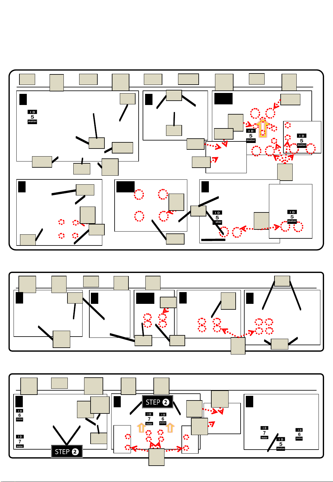
Bioloid Probing Robot – Getting Started
Attach ID5, F2, F3, and F10 together. (Do not misalign horn position.)
F3
x 2
F
x 1
2
F10
x 2
1 2
F3
S12
BU
3 43-
S4
F10
N
1
F3
W
x 1
A
F2
S-B
W
A
1
BU
x 1
F3
F2
F10
S-B
x 1
S1
2-
x 4
2
S4
x 4
N
1
S12
x 4
1
S
1
S-B
BU
WA
N
1
S
4
F3
S
1
x 2
Attach F1, F9, and F11 together.
F1
x 2
1
1
F
9
F1
1
x 2
F9
F1
S
x 2
1
2
x 8
F1
N
x 8
1
3
1
1
N1
F9
F
1
42-
S
1
F1
F1
1
Attach STEP①, STEP②, ID6, and ID7 together. (Do not misalign horn position.)
x 2
BU
x 2
W
A
1
S-
x 2
B
S-
W
B
A
BU
S
x 8
1
2
N
x 8
1
S-
B
U
W
A
B
3
N
1
3
Page 4
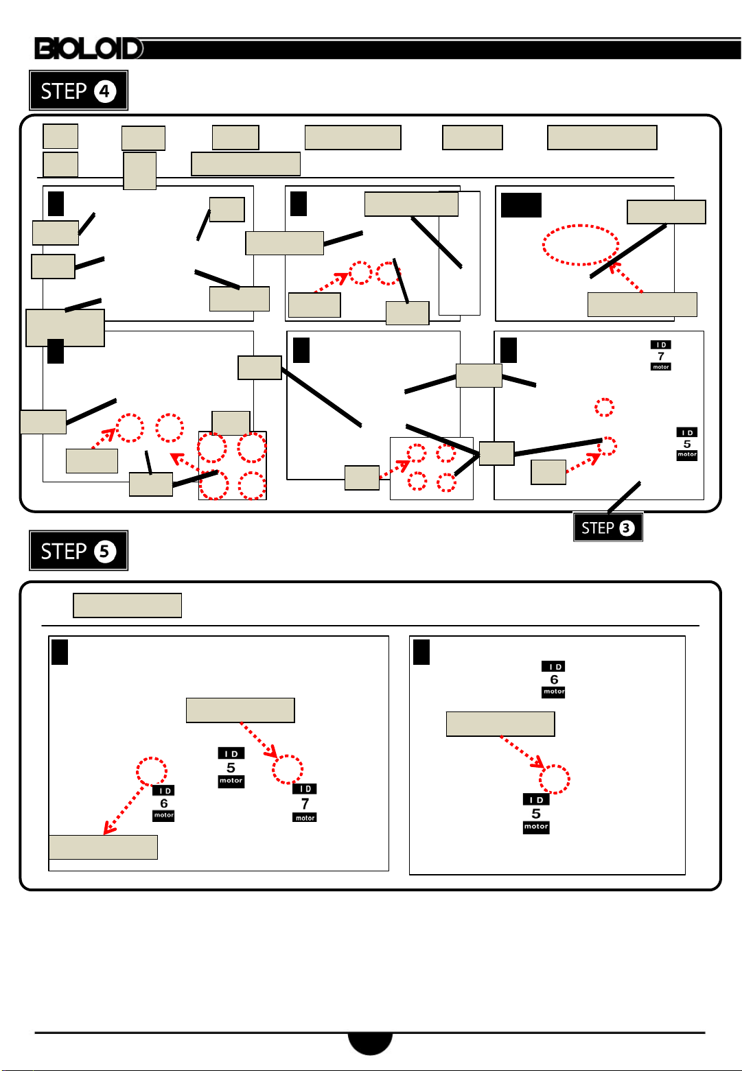
F3
x 1
Attach STEP③, F3, F54, IR SENSOR, and DMS together.
F54
x 1
DMS
x 1
IR SENSOR
x 1
RIVET
x 4
5P CABLE-15
x 1
DMS
F54
SENSOR
DMS
S1
1
3
IR
x 8
RIVET
N
x 4
1
CABLE-DMS
F3
SENSOR
RIVET
IR
x 1
2
RIVET
5P CABLE-15
F54
4 5
F54
N1
F54
S1
With 2 CABLE-10, connect ID5 to ID7; ID6 to ID7.
Connect ID5 with CABLE-10.
DMS
F3
2-
1
5P CABLE-15
S1
IR
SENSOR
CABLE-10
x 3
1 2
CABLE-10
CABLE-10
CABLE-10
4
Page 5
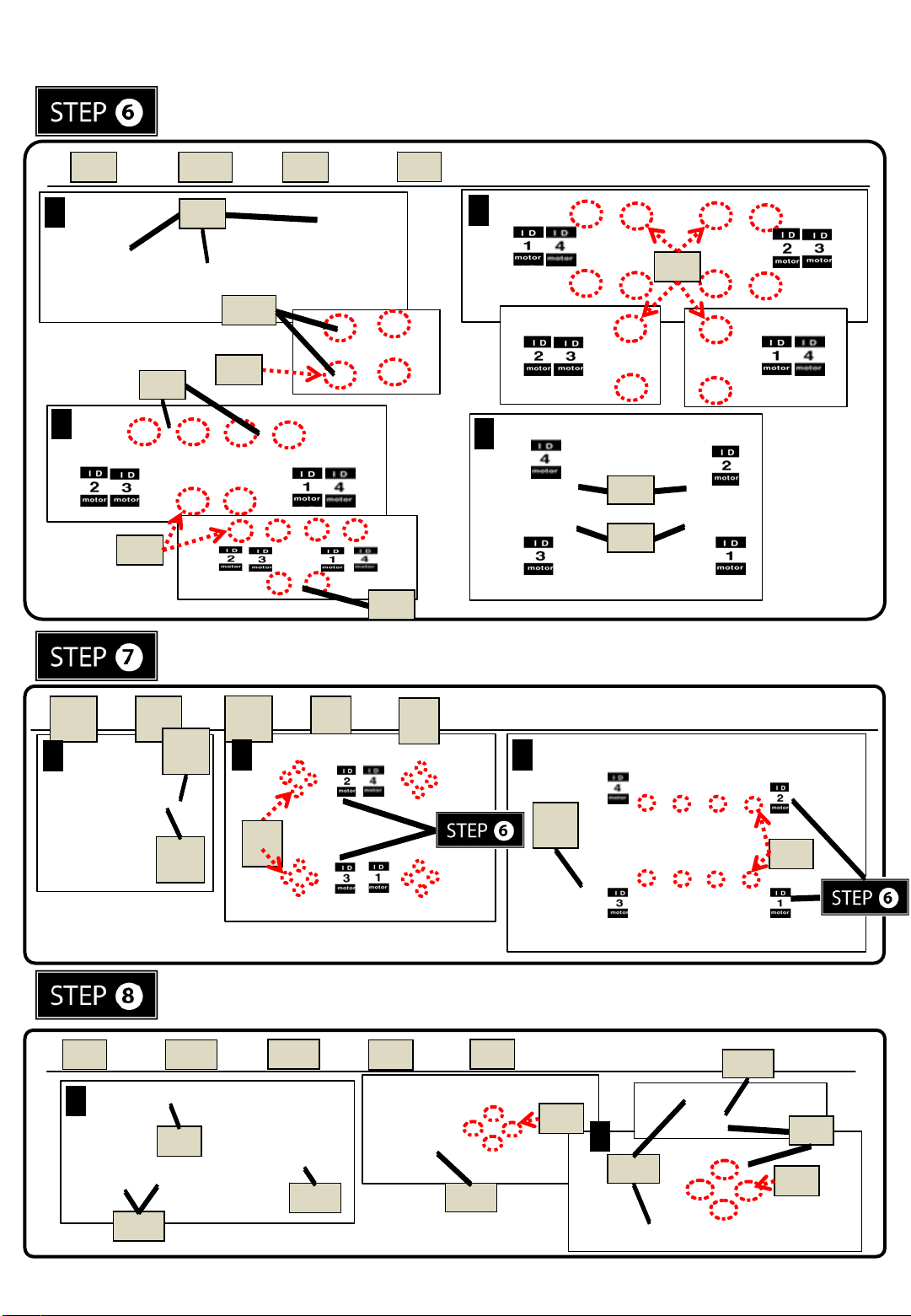
Attach ID1 through ID4, F3, and F55 together.
F3
N1
x 36
2
N1
4
F3
F3
F3
x 6
1
F3
F55
F3
x 8
F55
N1
S1
x 24
3
S1
Attach STEP⑥, F13, F14, and F51 together.
F1
3
1
x 4
F1
4
F1
4
F1
3
x 4
F5
x 1
1
S
x 8
1
S
x 16
2
32
F5
S
2
1
S1
Attach F3, F10, and F60 together.
1
F3
x 1
F10
F3
F10
x 2
F60
F60
x 1
S5
x 4
F60
N1
x 4
S5
F10
x 2
2
F60
F3
N1
5
Page 6
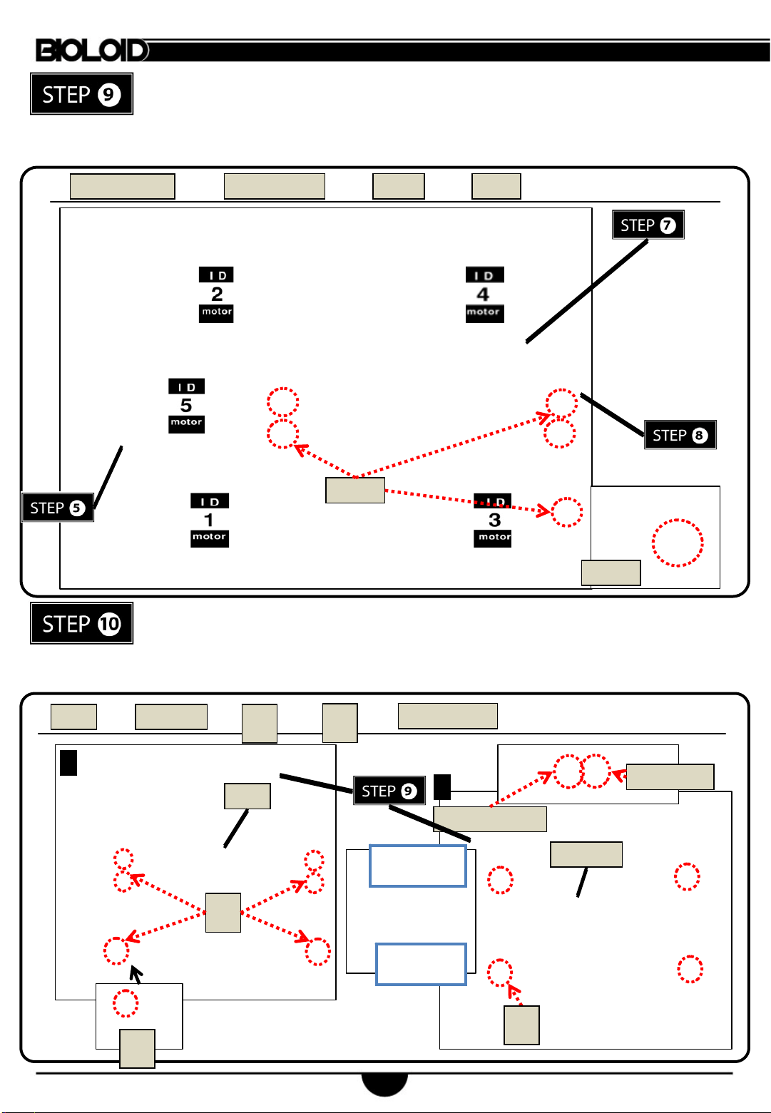
Attach STEP⑤, STEP⑦, and STEP⑧ together.
Connect ID4 to ID5 with CABLE-10.
With 3 CABLE-6, connect ID2 to ID4; ID1 to ID2; ID1 to ID3.
Connect ID 3 with CABLE-20.
CABLE-6
x 3
CABLE-6
x 3
S1
S1
x 5
N1
x 1
N1
F52
1
x 1
Attach STEP⑨, F52, and CM-510 together.
Connect ID3 to CM-510 with CABLE-20.
Connect IR SENSOR to Port 2 of CM-510 with 5P CABLE-15.
Connect DMS to Port 1 of CM-510 with CABLE-DMS.
CM-510
N
1
x 1
S
x 4
x 10
S
1
F52
1
N
1
CABLE-BAT
2
CABLE-BAT
PORT 2 (||)
IR SENSOR
PORT 1 ( | )
DMS
x 1
S
1
CABLE-20
CM-510
6
Page 7
Connect the battery through the battery cable.
BATTERY
1
BATTERY
x 1
2
3
7
Page 8
Assembly Check
After assembly please check the following procedure to ensure correctness.
Run the assembly check program
Set the robot in PLAY mode; hold the D button then press START.
Once the START button is pressed, the assembly check program begins.
AX12+ initial position and ID check
Select each actuator separately and compare it to the picture below.
Ensure the actuators’ horns are properly aligned (the horn’s notch should be aligned with the actuator’s).
Pressing the U or D button selects one actuator at a time.
The selected actuator’s LED lights up and goes to its initial position.
Check starts from ID1.
U moves to the next ID in ascending numerical order; D, in descending numerical order.
If the actuator’s ID does not exist, then the robot beeps.
Although the LED may lit if there is no power, then check the wiring on the actuator.
8
 Loading...