

User Manual

PAGE IS LEFT BLANK INTENTIONALLY.

Contents
INTRODUCTION ................................................................................................................... 7
1 OVERVIEW ....................................................................................................................... 8
2 INDICATIONS FOR USE .................................................................................................. 9
3 SPECIFICATIONS ............................................................................................................ 12
3.1 Dimensions .................................................................................................................................... 12
3.2 Electrical ........................................................................................................................................ 12
3.3 Air and Water Spray ...................................................................................................................... 12
3.4 Optical ........................................................................................................................................... 12
4 EQUIPMENT DESCRIPTION ......................................................................................... 13
4.1 System Components ..................................................................................................................... 13
4.2 General .......................................................................................................................................... 13
4.2.1 Laser console ........................................................................................................................ 14
4.2.2 Tablet ..................................................................................................................................... 17
4.2.3 Fiber Delivery System ........................................................................................................... 17
4.2.4 Wireless Footswitch ............................................................................................................... 18
5. CONTRAINDICATIONS, WARNINGS, AND PRECAUTIONS ....................................... 19
5.1 Contraindications ........................................................................................................................... 19
5.2 Warnings and Precautions ............................................................................................................19
6. SAFETY WITH THE WATERLASE EXPRESS ............................................................... 22
6.1 Safety Measures ........................................................................................................................... 22
6.2 Safety Classication ...................................................................................................................... 22
6.3 Safety Instructions ......................................................................................................................... 23
6.4 Safety Features ............................................................................................................................. 24
7. INSTALLATION AND SETUP ......................................................................................... 25
7.1 Facility Requirements .................................................................................................................... 25
7.2 Environmental Requirements ........................................................................................................ 25
7.3 Setup Requirements ...................................................................................................................... 26
7.3.1 Connecting the Laser System ............................................................................................... 26
7.3.2 Using the Remote Interlock ................................................................................................... 27
7.3.3 Installing the Handpiece Holder ............................................................................................. 27
7.3.4 Installing the Tablet ................................................................................................................ 28
Waterlase Express User Manual
3

Contents
7.3.5 Filling the Patient Water Bottle ..............................................................................................29
7.3.6 Installing the Fiber Optic Cable Support Arm ........................................................................30
7.3.7 Connecting the Fiber Optic Cable ......................................................................................... 31
7.3.8 Installing the Fiber Optic Cable Retainer ............................................................................... 32
7.3.9 Connecting/Disconnecting the Handpiece to the Fiber Optic Cable ...................................... 33
7.3.10 Installing and Changing the Tip in the Handpiece ...............................................................34
7.3.11 First Time Start-up ...............................................................................................................35
7.3.12 Enabling BIOLASE CONNECT ...........................................................................................37
8. OPERATING INSTRUCTIONS ....................................................................................... 38
8.1 Overview ....................................................................................................................................... 38
8.2 Tablet Holder - Function Control Button and LED Indicators ......................................................... 38
8.3 Daily Start-up ................................................................................................................................. 39
8.3.1 Initiating the Laser from OFF Status ...................................................................................... 39
8.3.2 Waking the system from SLEEP mode ..................................................................................40
8.4 Activating the Waterlase Express .................................................................................................. 40
8.5 Turning the Waterlase Express Off ................................................................................................ 41
9. USER INTERFACE ......................................................................................................... 42
9.1 Icons - Denition ............................................................................................................................ 42
9.2 Main Menu ..................................................................................................................................... 44
9.2.1 Learning Center ..................................................................................................................... 44
9.2.2 Settings .................................................................................................................................. 45
9.2.3 System Information ................................................................................................................ 45
9.2.4 Maintenance .......................................................................................................................... 46
9.2.5 Session Review ..................................................................................................................... 46
9.2.6 Web Portal ............................................................................................................................. 47
9.3 Home (Procedures Main) Screen .................................................................................................. 48
9.4 Favorites ........................................................................................................................................ 50
9.4.1 Create a Favorite ................................................................................................................... 50
9.4.2 Rename or Delete a Favorite ................................................................................................ 51
9.4.3 Adjusting the Handpiece, Aiming Beam, and Illumination ..................................................... 51
9.5 Presets .......................................................................................................................................... 52
9.6 Basic Mode .................................................................................................................................... 52
9.7 Advanced Mode ............................................................................................................................. 52
9.7.1 Accessing Advanced Mode .................................................................................................... 53
9.7.2 Software/Firmware/Content Updates .................................................................................... 54
9.8 System Flow Chart ........................................................................................................................ 55
4
Waterlase Express User Manual

Contents
10 CUTTING TISSUE .......................................................................................................... 56
10.1 Hard-tissue Cutting ...................................................................................................................... 56
10.2 Soft-tissue Cutting ....................................................................................................................... 57
11 CLEANING, DISINFECTION, AND STERILIZATION .................................................... 58
12 MAINTENANCE ............................................................................................................ 61
12.1 Daily Care of the Tablet and Console .......................................................................................... 61
12.2 Annual Maintenance .................................................................................................................... 61
12.3 Service and Calibration ............................................................................................................... 61
12.4 Tip Inspection .............................................................................................................................. 61
12.4.1 Tip Inspection Instructions (Using the Tip Cleaning and Inspection Kit) ..............................62
12.4.2 Inspecting the Plastic Ferrule .............................................................................................. 63
12.5 Tip Cleaning ................................................................................................................................63
12.6 Handpiece Mirror Inspection ....................................................................................................... 64
12.6.1 Removing the Handpiece Mirror .......................................................................................... 64
12.6.2 Changing the Handpiece Mirror ........................................................................................... 65
12.6.3 Mirror Alignment Check .......................................................................................................65
12.7 Fiber Optic Cable Check ............................................................................................................. 66
12.7.1 Replacing the Protective Window ........................................................................................ 67
12.8 Installing/Replacing the Wireless Footswitch Batteries ............................................................... 68
12.9 Pairing the Footswitch and Laser ................................................................................................ 68
12.9.1 Pairing the Footswitch and Laser ........................................................................................ 69
12.9.2 Selecting the Footswitch Channel ....................................................................................... 70
12.10 Internal Cooling Water Reservoir ..............................................................................................71
12.10.1 Filling the Internal Cooling Water Reservoir ...................................................................... 71
12.10.2 Draining the Internal Cooling Water Reservoir .................................................................. 72
12.11 Transportation ............................................................................................................................73
12.12 Storage ...................................................................................................................................... 73
13. TROUBLESHOOTING .................................................................................................. 74
13.1 Troubleshooting ........................................................................................................................... 74
13.1.1 Error Messages ................................................................................................................... 74
13.1.2 Problem/Warning Messages................................................................................................77
Waterlase Express User Manual
5
Contents
APPENDIX A – LABELS .................................................................................................... 78
APPENDIX B – ACCESSORIES/SPARE PARTS .............................................................. 84
APPENDIX C – TIPS........................................................................................................... 85
APPENDIX D – ELECTROMAGNETIC COMPATIBILITY .................................................. 87
APPENDIX E – WIRELESS EQUIPMENT COMPLIANCE STATEMENT .......................... 91
INDEX.................................................................................................................................. 92
Waterlase Express is indicated for professional use on dental patients. Procedures must be
performed only by licensed dental practitioners in a dental facility. Use of this device requires
clinical and technical training, and this manual provides instructions for use.
The Waterlase Express tablet contains video animations which demonstrate specic clinical
applications available with the device. All statements of individual claims presented are based
on references which can be viewed within the White Paper section of the Learning Center on
the Waterlase Express tablet.
CAUTION: From time to time you may see software related updates from Samsung, please
do not accept or execute software related updates without further instruction from BIOLASE
to ensure that updates will not adversely impact the use of your Waterlase Express.
6
Waterlase Express User Manual

Overview Introduction
Congratulations on the addition of the Waterlase Express™ all-tissue laser to your practice! Waterlase
patented technology provides a minimally invasive, highly precise, and exceptionally gentle dental
experience for your patients, as well as unmatched results in treatment outcomes.
This User Manual is designed to help you become familiar with the operation and functions of the laser
system. Read it carefully before using the laser clinically, follow all safety instructions and cautions, and
always have it accessible as a reference.
We appreciate your commitment to better care and know your investment in this technology is a sound
foundation for the successful growth of your practice.
BIOLASE Team
Waterlase Express User Manual
7

1 Overview1 Overview
The Waterlase Express all-tissue laser is a unique Er,Cr:YSGG* solid state tissue-cutting system
manufactured by BIOLASE for use in oral hard- and soft-tissue dental applications. It sets a new
standard of affordability, accessibility, and ease of use for all-tissue lasers.
Waterlase Express utilizes advanced laser and water atomization technologies to safely and effectively
cut, shave, contour, roughen, etch, and resect oral hard-tissues, and direct laser energy to perform oral
soft-tissue removal, incision, excision, ablation and coagulation. Waterlase Express may also be used
for specic endodontic and periodontal applications.
When used for oral hard tissue procedures, the Waterlase Express laser provides optical energy to a
user-controlled distribution of atomized water droplets and hydrated surface layer of hard-tissue. The
water present in the target tissue absorbs laser radiation, resulting in explosive molecular expansion
and ablation of hard-tissue. The water in the spray provides cooling and hydration for the target tissue.
For oral soft-tissue procedures, the Waterlase Express laser applies optical energy to the soft-tissue for
tissue removal, incision, excision, ablation and coagulation, using direct laser energy. These procedures
can be done in conjunction with water, for cooling and hydration, or without water, for coagulation.
A exible Fiber Optic Cable connects at one end to the laser and at the other to a Handpiece that
delivers laser energy to the target tissue through a ber Tip. A visible light emitted from the Handpiece
head illuminates the area of treatment. Certain laser parameters may be adjusted by the user for both
soft- and hard-tissue applications. The laser is activated using a Wireless Footswitch.
A removable Tablet serves as the user interface. Through the Tablet, the user may select laser
procedures, access information on the system’s clinical performance, and view educational and
reference materials. The user may also utilize the Tablet to communicate directly with BIOLASE
customer care, educators, and peer professionals. Additional service needs are also provided
through the Tablet, but no patient data of any kind is stored on the Tablet itself or the laser system.
Waterlase Express is indicated for professional use on dental patients. Procedures must be performed
only by licensed dental practitioners in a dental facility. Use of this device requires clinical and technical
training, and this manual provides instructions for use.
If used and maintained properly, Waterlase Express will prove a valuable addition to your practice.
Please contact BIOLASE customer service at 1-800 -321-6717 in the U.S. and Canada for
any service needs; if you are located outside North America, please contact your BIOLASE-
authorized representative.
In Canada, this device must be installed, operated, and maintained according to the current revision
of the guidelines specied in the Canadian standard CAN/CSA-Z386:2014 safe use of lasers in
health care.
*Erbium, Chromium: Yttrium-Scandium-Gallium-Garnet
8
Waterlase Express User Manual
2 Indications for Use2 Indications for Use
The Waterlase Express may be used for the following indications:
GENERAL HARD-TISSUE INDICATIONS*
• Class I, II, III, IV and V cavity preparation
• Caries removal
• Hard-tissue surface roughening or etching
• Enameloplasty, excavation of pits and ssures for placement of sealants
*For use on adult and pediatric patients
ROOT CANAL HARD-TISSUE INDICATIONS
• Tooth preparation to obtain access to root canal
• Root canal preparation including enlargement
• Root canal debridement and cleaning
ROOT CANAL DISINFECTION
• Laser root canal disinfection after endodontic treatment
ENDODONTIC SURGERY (ROOT AMPUTATION) INDICATIONS
• Flap preparation – incision of soft-tissue to prepare a ap and expose the bone
• Cutting bone to prepare a window access to the apex (apices) of the root(s)
• Apicoectomy – amputation of the root end
• Root end preparation for retroll amalgam or composite
NOTE: Any tissue growth (i.e., cyst, neoplasm or other lesions) must be submitted to a
qualied laboratory for histopathological evaluation.
• Removal of pathological tissues (i.e., cysts, neoplasm or abscess) and hyperplastic tissues
(i.e., granulation tissue) from around the apex
BONE SURGICAL INDICATIONS
• Cutting, shaving, contouring and resection of oral osseous tissues (bone)
• Osteotomy
SOFT-TISSUE INDICATIONS INCLUDING PULPAL TISSUES*
Incision, excision, vaporization, ablation and coagulation of oral soft-tissues, including:
• Excisional and incisional biopsies
• Exposure of unerupted teeth
Waterlase Express User Manual
9

2 Indications for Use2 Indications for Use
SOFT-TISSUE INDICATIONS INCLUDING PULPAL TISSUES* (CONTINUED)
• Fibroma removal
• Flap preparation – incision of soft-tissue to prepare a ap and expose the bone
• Flap preparation – incision of soft-tissue to prepare a ap and expose unerupted teeth
(hard and soft-tissue impactions)
• Frenectomy and frenotomy
• Gingival troughing for crown impressions
• Gingivectomy
• Gingivoplasty
• Gingival incision and excision
• Hemostasis
• Implant recovery
• Incision and drainage of abscesses
• Laser soft-tissue curettage of the post-extraction tooth sockets and the periapical area during
apical surgery
• Leukoplakia
• Operculectomy
• Oral papillectomies
• Pulpotomy
• Pulp extirpation
• Pulpotomy as an adjunct to root canal therapy
• Root canal debridement and cleaning
• Reduction of gingival hypertrophy
• Removal of pathological tissues (i.e., cysts, neoplasm or abscess) and hyperplastic tissues
(i.e., granulation tissue) from around the apex
NOTE: Any tissue growth (i.e., cyst, neoplasm or other lesions) must be submitted to a
qualied laboratory for histopathological evaluation.
• Soft-tissue crown lengthening
• Treatment of canker sores, herpetic and aphthous ulcers of the oral mucosa
• Vestibuloplasty
*For use on adult and pediatric patients
10
Waterlase Express User Manual

2 Indications for Use2 Indications for Use
LASER PERIODONTAL PROCEDURES
• Full thickness ap
• Partial thickness ap
• Split thickness ap
• Laser soft-tissue curettage
• Laser removal of diseased, infected, inamed and necrosed soft-tissue within the
periodontal pocket
• Removal of highly inamed edematous tissue affected by bacteria penetration of the pocket
lining junctional epithelium
• Removal of granulation tissue from bony defects
• Sulcular debridement (removal of diseased, infected, inamed or necrosed soft-tissue in the
periodontal pocket to improve clinical indices including gingival index, gingival bleeding index,
probe depth, attachment loss and tooth mobility)
• Osteoplasty and osseous recontouring (removal of bone to correct osseous defects and create
physiologic osseous contours)
• Ostectomy (resection of bone to restore bony architecture, resection of bone for grafting, etc.)
• Osseous crown lengthening
• Removal of subgingival calculi in periodontal pockets with periodontitis by closed or open curettage
• Waterlase Er,Cr:YSGG assisted new attachment procedure (cementum-mediated periodontal
ligament new-attachment to the root surface in the absence of long junctional epithelium)
Waterlase Express User Manual
11

3 Specications3 Specications
3.1 DIMENSIONS
• Laser console (W x L x H) 9 x 18 x 12 in (23 x 46 x 30.5 cm)
• Tablet (W x H x D) 6.7 in x 9.3 in x 0.2 in (16.9 cm x 23.8 cm x 0.6 cm)
• Screen size 9.7 in (24.6 cm)
• Weight laser console (with water) 27.2 lbs (12.3 kg)
• Weight Tablet 0.9 lbs (390 g)
3.2 ELECTRICAL
Class I Medical Electrical (ME) Equipment
• Operating voltage 100 - 240 VAC
• Frequency 50 / 60 Hz
• Current rating 6A / 3A
• Main control Main Power Switch
• On / Off control Keyswitch
• Remote interruption Remote interlock connector
3.3 AIR AND WATER SPRAY
• Water type Distilled or De-Ionized only
• External air source 60-120 psi. (4.1 – 8.2 bar)
• Water 0 - 100%
• Air 0 - 100%
3.4 OPTICAL
• Laser classication IV (4)
• Medium Er,Cr:YSGG
• Wavelength 2.78 µm (2780nm)
• Mode Free-running Pulsed
• Frequency (Pulse Rate) 5 – 50 Hz
• Average power 0.1-4.0 W
• Power accuracy ± 20%
• Pulse energy 10– 250 mJ
• Pulse duration for “H” mode (Short pulse) 60 µs
• Pulse duration “S” mode (Long pulse) 700 µs
• Handpiece head angles 70° contra-angle
• Fiber Tip diameter range (Spot size) 200 – 1200 µm
• Output divergence ≥ 8° per side
• Aiming beam 625-670 nm (red) laser, 1mW max (Laser Class 1)
• Nominal ocular hazard distance (NOHD) 5cm
• Maximum permissible exposure (MPE) 3.46 X 10⁵W/m²
(Erbium, Chromium: Yttrium, Scandium, Gallium, Garnet)
12
Waterlase Express User Manual

4 Equipment Description4 Equipment Description
4.1 SYSTEM COMPONENTS
The Waterlase Express laser system includes the following*:
• Laser Console
• Tablet and International AC Adapter
(packed separately)
• Tablet Protective Covers
• Fiber Optic Cable
• Fiber Optic Cable Support Arm
• Fiber Optic Cable Retainer
• Yellow Air Tube
• Laser Protective Eyewear (3)
• Handpieces (2)
• Handpiece Holder
• Fiber Tip Starter Kit (Assorted Tips)
• Fiber Tip Holder
*Additional accessories, including extra Handpieces, Tips, and screen protectors may be ordered
separately from BIOLASEstore.com.
• Internal Reservoir Fill Kit
• Tip Cleaning and Inspection Kit
• Power Cord (1-US, 1-Int’l, 1-UK)
• Remote Interlock Plug
• Wireless Footswitch
• Footswitch Batteries
• Welcome Kit – Includes:
• Welcome Letter
• Waterlase Express User Manual
• Waterlase Express Quick Start Guide
• Laser Warning Sign
• Product Registration Flyer
• Limited Warranty
4.2 GENERAL
The Waterlase Express laser system consists of four primary components:
1. Laser Console
2. Tablet
3. Fiber Delivery System
4. Wireless Footswitch
Waterlase Express User Manual
13

4 Equipment Description4 Equipment Description
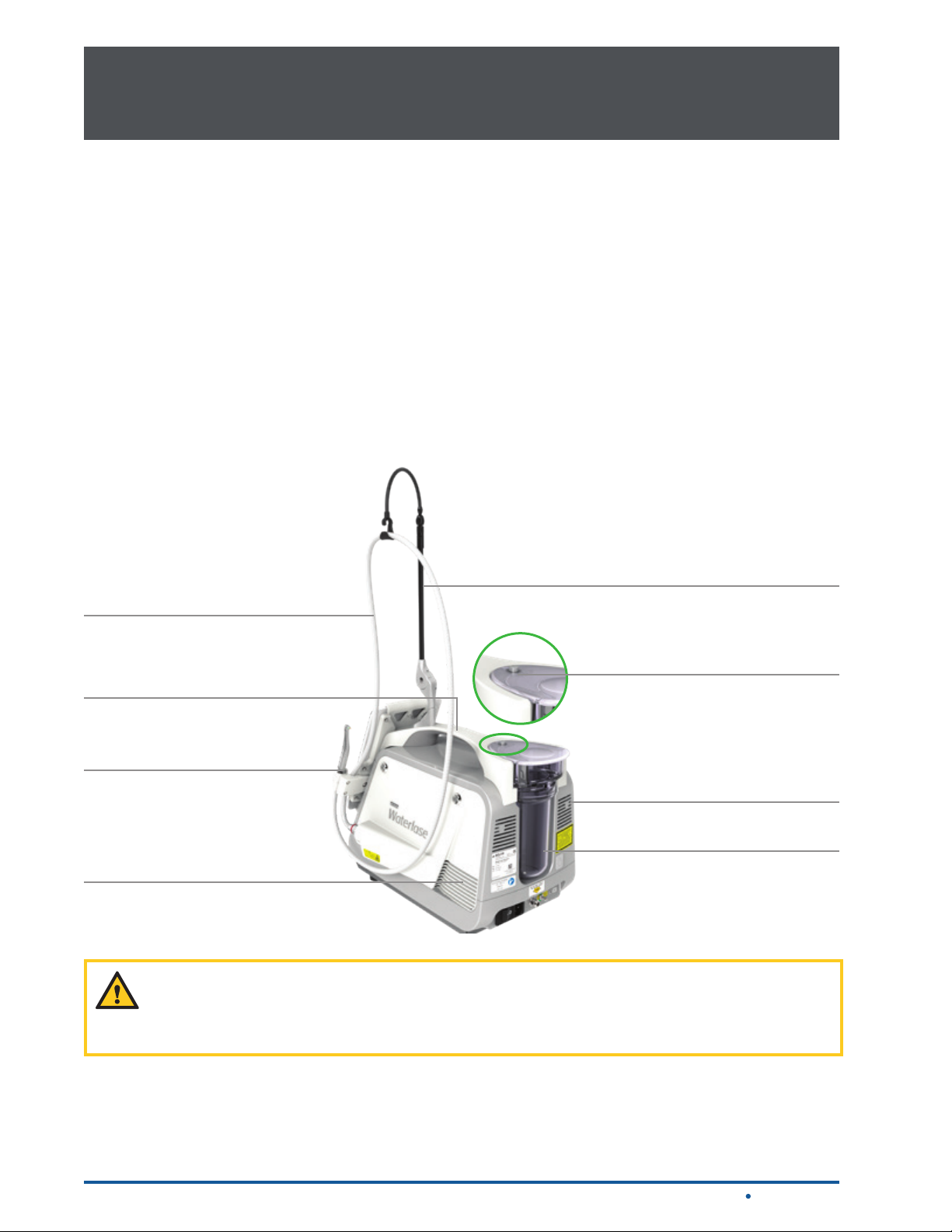
4.2.1 LASER CONSOLE
POWER CONNECTION/MAIN POWER SWITCH
The power cord attaches to the back panel of the laser console. The other end must be plugged into an
electrical power source in order for the laser system to work. The main power switch serves as a line
switch to separate the console from the main power supply (O = OFF, I = ON)
Internal Reservoir Connector
Remote Interlock Outlet
Air Inlet Connector
Power Connection | Main Power Switch
Figure 4.1
KEYSWITCH
Located on the right front panel of the laser console, the Keyswitch is used to turn the laser ON by
turning the key clockwise to a horizontal position; always use only the key provided. The key cannot be
removed while it is in the ON position. Always remove the key when the laser is left unattended.
EMERGENCY STOP
The emergency stop (red) button is located on the left front panel of the laser console. Pressing this
button instantly stops the emission of laser energy; the button will glow red to indicate the emergency
stop has been engaged and the screen will display the message “Emergency Stop Pressed.”
14
Waterlase Express User Manual
4 Equipment Description
4 Equipment Description
TABLET HOLDER
The Tablet Holder is the hinged panel located at the front of the console and includes the control panel
and Tablet Latch. The Tablet is inserted into the control panel, once in place and connected to the
micro USB inside the panel, it is locked into position by ipping the Latch over the top of the Tablet (a
thumbscrew at the rear of the latch prevents removal of the tablet).
CONTROL PANEL
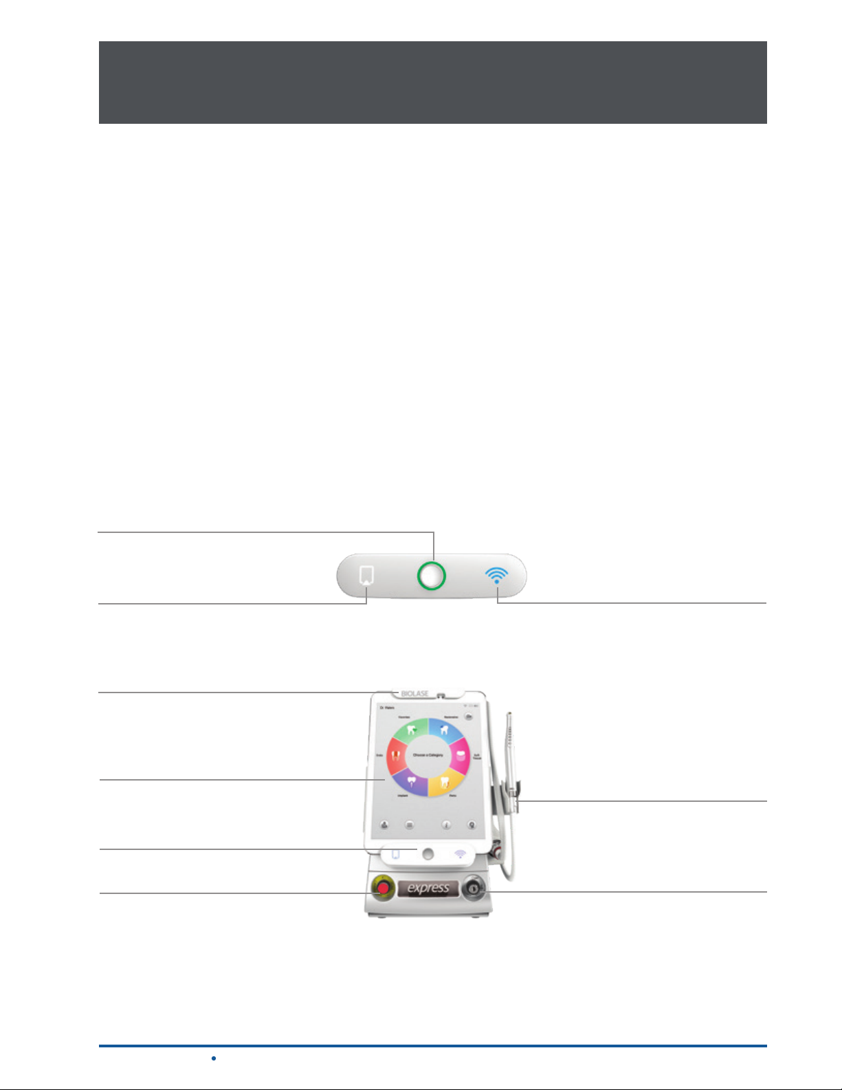
The Function Control button is located in the center of the control panel; it activates the controls and
display, and is used to place the system into Ready (green), Standby (amber), or Sleep mode.
There are also two LED indicators on either side of the function control button; one indicates the
Tablet is properly installed, and the other conrms the wireless connection with the Footswitch is active.
HANDPIECE HOLDER
The Handpiece Holder cradles the Handpiece when it is not in use. It can be attached to the Tablet
Holder on the right or the left, based on user preference.
Function Control Button
Tablet Connectivity Indicator
Tablet Latch
Table t
Tablet Holder/ Control Panel
Emergency Stop
Wireless Footswitch
Connectivity Indicator
Handpiece Holder
Keyswitch
Waterlase Express User Manual
Figure 4.2
15
4 Equipment Description4 Equipment Description
PATIENT WATER BOTTLE
This is a detachable water bottle located on the back of the console that is the water supply for the
Handpiece atomization spray. A push-button release is located on the top of the self-contained patient
water bottle that releases the bottle from the console for lling/relling with distilled or de-ionized water.
VENTILATION CHANNELS
The slots on the sides and rear of the console provide an air ow path to cool the laser system. Do
not cover or block these during use; leave a minimum of 4 inches between the laser console and any
wall or partition.
AIR INLET CONNECTOR
This adaptor on the back of the console provides the connection to a compressed dry air outlet at
60 – 120 psi (4.1 – 8.2 bar) using the yellow tubing provided.
Fiber Optic Cable
Handle
Handpiece
Ventilation Channels
CAUTION: Moisture or oil in the air supply line will damage the laser system. Always provide
an air dryer, mist separator, and proper ltration at the compressor output to eliminate all
moisture or oil from the air source. Any damage from moisture or oil in the air line is not
covered by the system warranty.
Fiber Support Arm
Patient Water Bottle Release
Ventilation Channels
Patient Water Bottle
Figure 4.3
16
Waterlase Express User Manual
4 Equipment Description4 Equipment Description
REMOTE INTERLOCK PLUG
This plug connects the laser to a door switch (not included). It will stop the laser immediately if the
operatory door is opened while the laser is in use. Although use of this feature is optional, the plug itself
must be inserted in the Remote Interlock Outlet at the rear of the console for the laser system to operate.
NOTE: To enable the interlock feature, call BIOLASE for instructions if necessary.
INTERNAL COOLING WATER RESERVOIR FILL CONNECTOR
The Waterlase Express laser system contains an internal cooling water reservoir which must be
lled prior to initial use of the laser. A reservoir ll kit is included with the system and attaches to the
connector on the rear of the console.
FIBER OPTIC CABLE SUPPORT ARM
This removable accessory supports the weight of the Fiber Optic Cable, keeping it from looping to the
ground; its use is optional, based on user preference.
HANDLE
Use the handle at the top of the console to lift, carry, or reposition the laser on a stable, at surface.
4.2.2 TABLET
The system is operated through a Tablet terminal display that has wireless remote access capability;
when Wi-Fi connectivity is activated, the Tablet allows remote access by BIOLASE for diagnostics,
software/rmware updates, and other system data requirements. No patient data is accessed. When
installed in the Tablet Holder, the Tablet will charge only if the power to the laser system is ON.
4.2.3 FIBER DELIVERY SYSTEM
FIBER OPTIC CABLE
The Fiber Optic Cable contains the optical ber together with the illumination waveguide, air tubing and
water tubing. Laser radiation is delivered from the laser to the Handpiece through the optical ber.
FIBER OPTIC CABLE RETAINER
Please note that a Fiber Optic Retainer, as described in Section 7.3.8, is included with your Waterlase
Express. This optional accessory is initially installed by your authorized Waterlase Field Service
Technician. The Fiber Optic Retainer is only installed if the Handpiece Holder is installed on the right
side of the Tablet holder. Its use is not recommended if the Handpiece Holder is installed on the left side
of the Tablet holder.
Waterlase Express User Manual
17
4 Equipment Description
4 Equipment Description
HANDPIECE
The Handpiece is re-usable, rotatable, and detachable from the Fiber Optic Cable and must be cleaned
and sterilized between patients (see section 11). It delivers optical energy, illumination, air, and atomized
water spray to the treatment area and utilizes a variety of Tips to focus the optical energy on the
selected treatment site.
A visible light emitted from the Handpiece head illuminates the area of treatment. The visible spot of
the aiming beam should be clear, uniform, and well-dened. If the aiming beam is not present while in
Ready mode or when the laser is ring, replace the Fiber Delivery System.
Cover
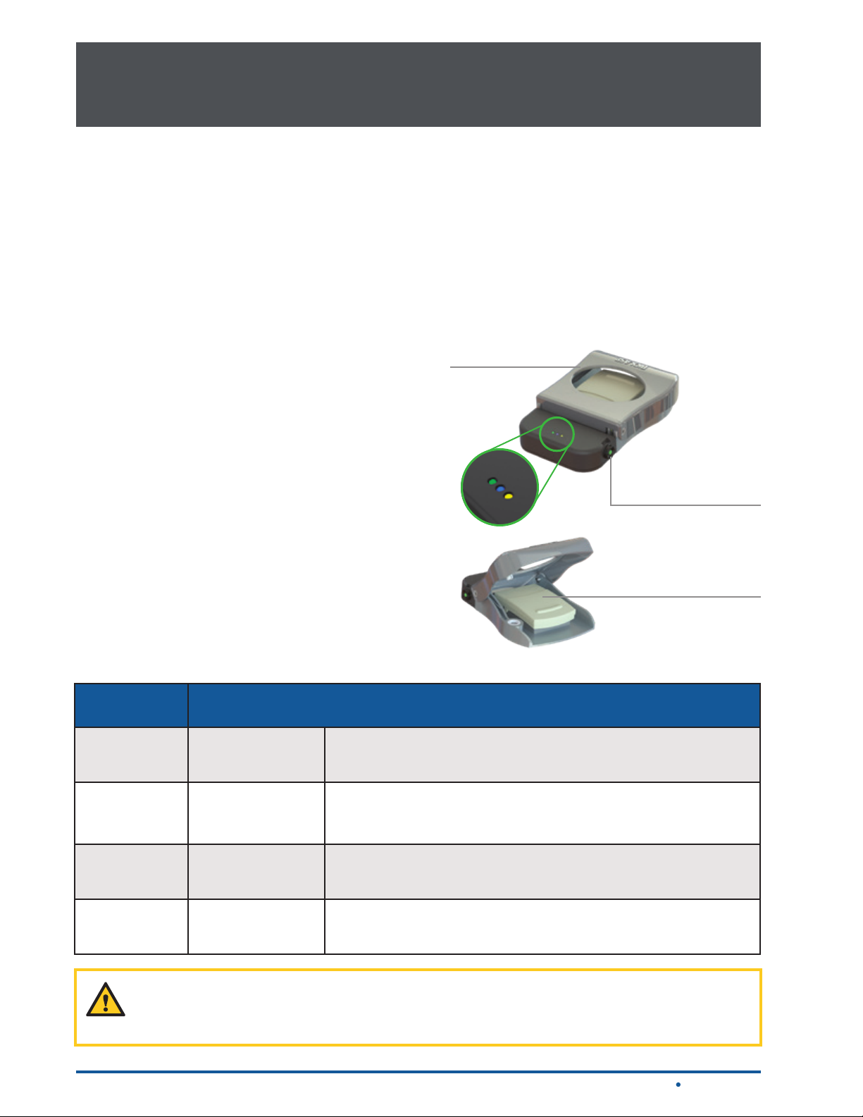
4.2.4 WIRELESS FOOTSWITCH
The Waterlase Express laser will only emit laser
energy when the user presses down on the Footswitch
while the laser is in Ready mode. It is designed to
pair with the laser console using wireless technology
and is powered by two (2) AAA batteries. (Refer to
Section 12 for instructions on how to replace the
Footswitch batteries
included with the system).
Pairing Button/
Battery
Compartment
Cover
The Footswitch is protected by the Footswitch Cover.
To access, press down on the Footswitch Cover.
Three separate LED indicator lights are displayed on
the top of the battery housing of the Footswitch.
LED Indicator Status
Blue Solid
Green Solid
Green Blinking The Footswitch batteries are low; replace the batteries.
Amber Blinking or Solid
The Footswitch is connecting to the laser, or has successfully
paired with the laser.
ON: The Footswitch is pressed while paired to the laser.
OFF: The Footswitch is not pressed, or the system is in Sleep
mode, or the batteries are dead.
A critical error or short has occurred; the relevant error message
will appear on the Tablet screen.
Footswitch
Figure 4.4
18
CAUTION: Repeated rapid tapping of the Footswitch may cause a system error; release the
Footswitch, wait 2 seconds, then press rmly down on the Footswitch to clear it. A system
restart is not required.
Waterlase Express User Manual

5 Contraindications, Warnings, and Precautions5 Contraindications, Warnings, and Precautions
5.1 CONTRAINDICATIONS
All clinical procedures performed with the Waterlase Express must be subjected to the same clinical
judgment and care as with standard techniques. Patient risk must always be considered and fully
understood before clinical treatment. The clinician must completely understand the patient’s medical
history prior to treatment and exercise caution for general medical conditions which might contraindicate
a local procedure. Such conditions may include, but are not limited to, allergy to local or topical
anesthetics, heart disease (e.g., pacemakers, implantable debrillators), lung disease, bleeding
disorders, or an immune system deciency. Medical clearance from the patient’s physician is advisable
when doubt exists regarding treatment.
5.2 WARNINGS AND PRECAUTIONS
PRESCRIPTION STATEMENT
U.S. Federal Law restricts this device to sale by or on the order of a dentist or other licensed
dental practitioner.
TRAINING
Only licensed professionals who have reviewed and understood this user manual and have received
proper training on how to correctly operate the system should use this device. Procedures related to
soft-Tissue, osseous, endodontic, or periodontal surgery should only be performed by clinicians who
have training and experience in Oral Maxillofacial, Periodontal, or Endodontic surgery.
EYEWEAR
Doctor, patient, assistant, and all others inside or entering the operatory must wear appropriate laser
protection eyewear for the 2780 nm wavelength (OD 3 or greater) whenever the laser is in use. Prior to
use, inspect eyewear for pitting and cracking; do not use if damaged.
CAUTION: Always check the eyewear specications as etched on the glasses to ensure they
offer the protection required for the laser wavelength.
ANESTHESIA
Although in many cases anesthesia may not be required, patients should be closely monitored for signs
of pain or discomfort. If such signs are present, adjust settings, apply anesthesia, or cease treatment
if required.
TREATMENT, TECHNIQUE, AND SETTINGS
Always start treatment at the factory-installed default settings for the chosen application and adjust
as required. Closely observe clinical effects and use your judgment to determine the aspects of the
treatment (e.g., technique, proper power, pulse mode, air and water settings, tip type, and duration of
operation) and make appropriate adjustments to compensate for varying tissue composition, density,
and thickness.
Waterlase Express User Manual
19

5 Contraindications, Warnings, and Precautions5 Contraindications, Warnings, and Precautions
CLINICAL ENVIRONMENT
Only use this device in clinical environments that observe proper standard aseptic techniques with all
oral procedures.
HARD-TISSUE PROCEDURES
All hard-tissue (enamel, dentin, cementum and bone) procedures must be performed using air and
water spray at appropriate settings. Failure to use the spray will result in tissue thermal damage.
SOFT-TISSUE PROCEDURES
Soft-tissue procedures can be performed using two pulse duration settings H-Mode and S-Mode, either
with water for cooling and hydration, or without water for coagulation.
The S-Mode (long pulse) settings are indicated for soft-tissue applications only. Do not use S-Mode
to perform hard tissue procedures.
FLUID ENTRAPMENT AND AIR EMBOLISM
Do not direct air or spray toward tissues that may trap air or water. For example, when performing
surgical procedures the clinician should be aware of adjacent soft-tissue pockets, cavities, or channels
that may collect or entrap air. Always use high-speed suction to remove any excess uid and avoid
directing the spray into deep pockets. Do not use the Waterlase Express if it is not possible to access
the treatment site without directing air into an area that may collect or entrap air. In general, the same
care and precautions should be taken when using the Waterlase Express as are taken when using any
air and water emitting cutting device.
ROOT CANAL PROCEDURES
The Waterlase Express is better suited for straight and slightly curved canals. Great care should be
taken during instrumentation of curved canals as the endodontic Fiber Tip may break or perforate
through the wall of these types of canals. If during insertion the Fiber Tip does not advance easily into
the canal, do not force it. If necessary, pull the Fiber Tip out and use an endodontic hand le or a broach
to open the path. Do not force the Tip and/or activate the laser while moving the Tip inside a narrow or
curved canal, or through the apex. Place the end of the Tip ~2mm from the apex or from being in contact
with the wall of a curved canal. Activate the laser and spray only during the outward stroke when the
Fiber Tip is pulled towards the coronal portion of the canal.
ROOT CANAL DISINFECTION PROCEDURES
The same precautions and warnings stated above are applicable to root canal disinfection procedures.
The Fiber Tips designed for this indication are the radial emitting RFT2 and RFT3, which have a 200 µm
and a 300 µm diameter, respectively, and come in various lengths to accommodate different root canal
lengths. Effective laser root canal disinfection is performed with air and no water spray. Do not exceed
the maximum air setting (10%) for this procedure.
20
Waterlase Express User Manual

5 Contraindications, Warnings, and Precautions5 Contraindications, Warnings, and Precautions
ADJACENT STRUCTURES
Always be aware of adjacent structures and substructures during treatment. Be extremely careful not
to inadvertently penetrate or ablate through underlying/adjacent tissues and be aware and use extreme
caution when working on tissue adjacent to major anatomical structures, such as nerves or vessels.
Exercise extreme care when using this device in areas such as pockets, where critical structures such
as nerves or vessels could be damaged. Do not proceed with using the laser if visibility in these areas
is limited.
TISSUE EVALUATION
Any tissue growth (i.e., cyst, neoplasm and other lesions), either removed with Waterlase Express or
conventionally, must be submitted to a qualied laboratory for histopathological assessment.
TISSUE CONTACT AND TIP BREAKAGE
Do not contact any hard surface with the Fiber Tip as it is very brittle and fragile and could break. If
the Fiber Tip should break during a procedure, immediately and carefully suction the debris from the
treatment site, rinse, and repeat.
FIBER TIP CHANGING
Failure to correctly replace the Fiber Tip could result in damage to the Fiber Tip and/or Handpiece, or
affect the emission of laser energy around the Tip. A careful review of the instructions on how to replace
the Fiber Tip is recommended (refer to Section 7.3.10).
WATER SPLASHING
Water from spray may splash during laser use. The use of a face shield as protection from spattering is
recommended. Use high-speed suction as required to maintain a clear eld of vision during a procedure.
Do not use the Waterlase Express if you cannot clearly see the treatment site.
PLUME REMOVAL
CAUTION: Laser plume may contain viable tissue particulates.
Special care must be taken to prevent infection from the laser plume generated by the vaporization of
virally or bacterially infected tissue during procedures utilizing the laser with minimal or no water spray.
Ensure that all appropriate protective equipment (including high-speed suction to remove the plume,
appropriate masks, and other protective equipment) is used at all times during procedures utilizing this
laser device.
DENTAL MATERIALS
Do not direct laser energy towards amalgam, gold, or other metallic surfaces. Do not direct energy
towards dental cements or other similar lling materials. Doing so, may damage the Waterlase Express
Fiber Tip and Fiber Optic Cable.
Waterlase Express User Manual
21

6 Safety with The Waterlase Express6 Safety with The Waterlase Express
6.1 SAFETY MEASURES
WARNING: No modication of this equipment is allowed.
Failure to comply with the following precautions and warnings may lead to exposure to dangerous
voltage levels or optical radiation sources. Please comply with all safety instructions and warnings.
CAUTION: Use of controls or adjustments, or carrying out procedures other than those
specied in this User Manual, may result in hazardous radiation exposure.
CAUTION: This Laser System has been designed and tested to meet the requirements of
severe electromagnetic, electrostatic, and radio frequency interference testing. However, the
possibility of electromagnetic or other interference may still exist.
DANGER: Invisible and/or visible laser radiation – avoid eye or skin exposure to direct or
scattered radiation. Do not use this Laser System in any manner other than as described in
this User Manual. Do not use the Laser System if you suspect it is not functioning properly;
contact BIOLASE for assistance.
NOTE: For Canada, this device must be installed, operated, and maintained according to the
current revision of the guidelines specied in the Canadian standard CAN/CSA-Z386:2014
Safe use of lasers in health care.
6.2 SAFETY CLASSIFICATION
The following safety classications are applicable to the device:
• Laser Radiation - Class 4
• Aiming Beam - Class 1
• Type of protection against electrical shock - Class 1
• Applied part, laser Handpiece – Type BF
• Not protected against water ingress - Ordinary Equipment
• Console - IPX0
• Footswitch – IPX6
• Not suitable for use in the presence of ammable anesthetic
• Not suitable for use in oxygen-rich environments
• Operation Mode – Free-running pulsed
22
Waterlase Express User Manual

6 Safety with The Waterlase Express6 Safety with The Waterlase Express
CAUTION: High temperatures produced in the normal use of this laser equipment may ignite
some materials (e.g., cotton wool when saturated with oxygen); solvents of adhesive and
ammable solutions used for cleaning and disinfecting should be allowed to evaporate before
the laser equipment is used.
6.3 SAFETY INSTRUCTIONS
Follow these safety instructions before and during treatments:
1. Remove or cover all highly reective items in the treatment area, if possible.
2. Do not operate in the presence of explosive or ammable materials.
3. All persons present in the operatory, including patients, must wear protective eyewear suitable for
blocking 2.78 µm (2780 nm) laser energy (OD 3 or greater, supplied by BIOLASE).
CAUTION: Prior to use, inspect eyewear for pitting and cracking; do not use if damaged. For
replacements or additional protective eyewear, please contact BIOLASE Customer Service
or your authorized local BIOLASE representative.
4. Do not look directly into the beam or at specular reections.
5. Direct the cutting spray toward targeted tissues only.
6. Place the laser system in Standby mode by pressing the Function Control button on the Tablet
Holder before changing the water in the patient water bottle, installing the Fiber Optic Cable,
attaching the Handpiece, changing a Fiber Tip, and turning off the laser system.
CAUTION: Only remove the Patient Water Bottle when the system is in Standby mode; the
Patient Water Bottle is pressurized while the system is in Ready mode.
7. Switch the circuit breaker to the OFF (O) position and remove the key before leaving the laser
unattended for long periods of time.
8. All operatory entrances must be marked with an approved warning sign (included with the laser
system) indicating a laser is in use.
DANGER: DO NOT open the side doors of the console as danger from radiation exposure
and high voltage may exist. These are to be opened only by authorized BIOLASE
service personnel.
9. Take special care to contain the laser plume, i.e., particles produced by the vaporization of
virally or bacterially infected tissue, during procedures utilizing the laser with minimal or no
water spray. Ensure that all appropriate protective equipment (including high-speed suction
to remove the plume, appropriate masks, and other protective equipment) is used at all times
during procedures.
NOTE: Please direct any safety questions to your authorized BIOLASE representative; US
and Canada, call BIOLASE at (888) 424 -6527, or BIOLASE Service at (800) 321-6717.
Waterlase Express User Manual
23

6 Safety with The Waterlase Express6 Safety with The Waterlase Express
6.4 SAFETY FEATURES
ENERGY MONITOR
The energy monitor checks power output. Power deviations of more than ± 20% and ± 50% for power
levels below 1 Watt from the selected value will cause the display to show the error message "Internal
HV System Error", the laser will not operate until the error is resolved, at which time the laser will be in
Standby mode; if the error message persists, please contact BIOLASE Service or your authorized
BIOLASE representative.
SYSTEM MONITOR
Waterlase Express continually monitors all system functions, including the Fiber Optic Cable, water
bottle status, air status, voltage, Tablet connection, and Wireless Footswitch connectivity. An error in any
one of these areas will stop the system and the Tablet will display an error message. Operation cannot
resume until the error is cleared. If the Tablet is not properly connected to the laser, the system will stay
in Standby mode until the Tablet is installed and the error is cleared.
EMERGENCY STOP
The emergency stop (red) button is located on the front panel of the laser console. Pressing this button
instantly stops the emission of laser energy; the button will glow red to indicate an emergency stop has
taken place and the screen will display the message “Emergency Stop Pressed.” To restart the laser
system, press the button a second time (the system will be activated in Standby mode).
REMOTE INTERLOCK
When used, this feature enables a cable to connect the laser to a remote switch/sensor attached to
a door. When the remote switch is activated, for example when the entrance door to the operatory is
opened while the laser is ring, it will immediately turn the laser off, protecting anyone entering from
inadvertent exposure to laser radiation.
NOTE: The remote interlock plug must be installed in the console in order for the system to
operate, even if the remote interlock function is not used.
WIRELESS FOOTSWITCH
Waterlase Express will only emit laser energy when the user presses down on the Footswitch while the
laser is in Ready mode. The Footswitch Cover shields the Footswitch to prevent it from being pressed
unintentionally. The protective cover can be opened or closed only by pressing down on it.
CIRCUIT BREAKER
The circuit breaker serves as a line switch to separate the console from the main power supply
(O = OFF, I = ON).
24
Waterlase Express User Manual
7 Installation and Set-Up7 Installation and Set-Up
The Waterlase Express laser system must be unpacked and installed by a qualied BIOLASE employee
or agent. Please leave the shipping container unopened until your trained representative arrives.
7.1 FACILITY REQUIREMENTS
NOTE: The main power supply of the Waterlase Express laser system has an isolation
transformer that complies with a Transient Voltage of 4kV.
ELECTRICAL SUPPLY: 100VAC @ 6.0 Amps max to 240VAC @ 3.0 Amps, 50/60 Hz
COMPRESSED AIR SUPPLY: 60 -120 psi (4.1 – 8.2 bar)
CAUTION: Moisture in the air supply line may damage the laser system. Always provide
an air dryer, mist separator, and proper ltration at the compressor output to eliminate all
moisture from the air source. If water is introduced into the air supply line call your authorized
BIOLASE service representative for assistance.
7.2 ENVIRONMENTAL REQUIREMENTS
TEMPERATURE: 15 – 30 °C
HUMIDITY: 20% - 80%, non-condensing
ATMOSPHERIC PRESSURE (altitude):
Functional: 80KPa (2000 meters) to 102kPa (-56meters)
Storage: 50KPa (4944 meters) to 102KPa (-56 meters)
AIR SUPPLY: Connections for an air supply must be available in each operatory. Attach an air hose
with a ¼ inch outside diameter male quick connector on each end between the air inlet connector and
the operatory air source.
CAUTION: Prior to connecting the yellow air hose, verify that the outlet is for the air, NOT the
water supply. Connection to the water supply may cause damage to the Waterlase Express
system. If the laser system is connected to the water supply, DO NOT turn the system on;
contact your service representative. Any damage resulting from connecting the air line to the
water supply is not covered by the system warranty.
CAUTION: DO NOT position this equipment so that it is difcult to pull the plug from the
power source.
WARNING: To avoid the risk of electric shock, this equipment must only be connected to a
supply mains with protective earth.
Waterlase Express User Manual
25

7 Installation and Set-Up7 Installation and Set-Up
7.3 SETUP REQUIREMENTS
The Waterlase Express is designed to be transportable between operatories either manually, using the
console handle, or by wheeling it on the custom cart offered as a system option. In either case, prior
to use the laser must be properly set up, as described in this user manual, to ensure safe and efcient
functionality.
7.3.1 CONNECTING THE LASER SYSTEM
To ensure proper operation, always place the laser console upright on a at, clean, dry surface a
minimum of four (4) inches from any wall.
CAUTION: Waterlase Express ships from the factory with the internal cooling water reservoir
empty. Before rst-time use, the reservoir must be lled with distilled or de-ionized water
using the reservoir ll kit included with the laser system. For instructions on how to ll the
reservoir, refer to section 12.10. DO NOT USE TAP WATER.
1. Verify the main power switch is in the OFF position.
2. Verify the Keyswitch is in the OFF position.
3. Connect the power cord to the rear of the console.
4. Verify the minimum air pressure of 60 psi (4.1 bar) is emitted from the air supply (max 120 psi,
8.2 bar). Using air pressure greater than 120 psi may damage the internal components of the
laser system.
5. Check the air supply for moisture.
6. Connect the air supply to the console’s air inlet connector at the rear of the console with the yellow
tubing provided.
CAUTION: DO NOT connect the operatory air supply to the console if water or oil is
present. The air compressor may need to be drained or cleaned. Install an air dryer, mist
separator, and proper ltration. Wet air will damage the laser system. Check the air supply
weekly to verify the absence of water and oil.
26
Waterlase Express User Manual
7 Installation and Set-Up7 Installation and Set-Up
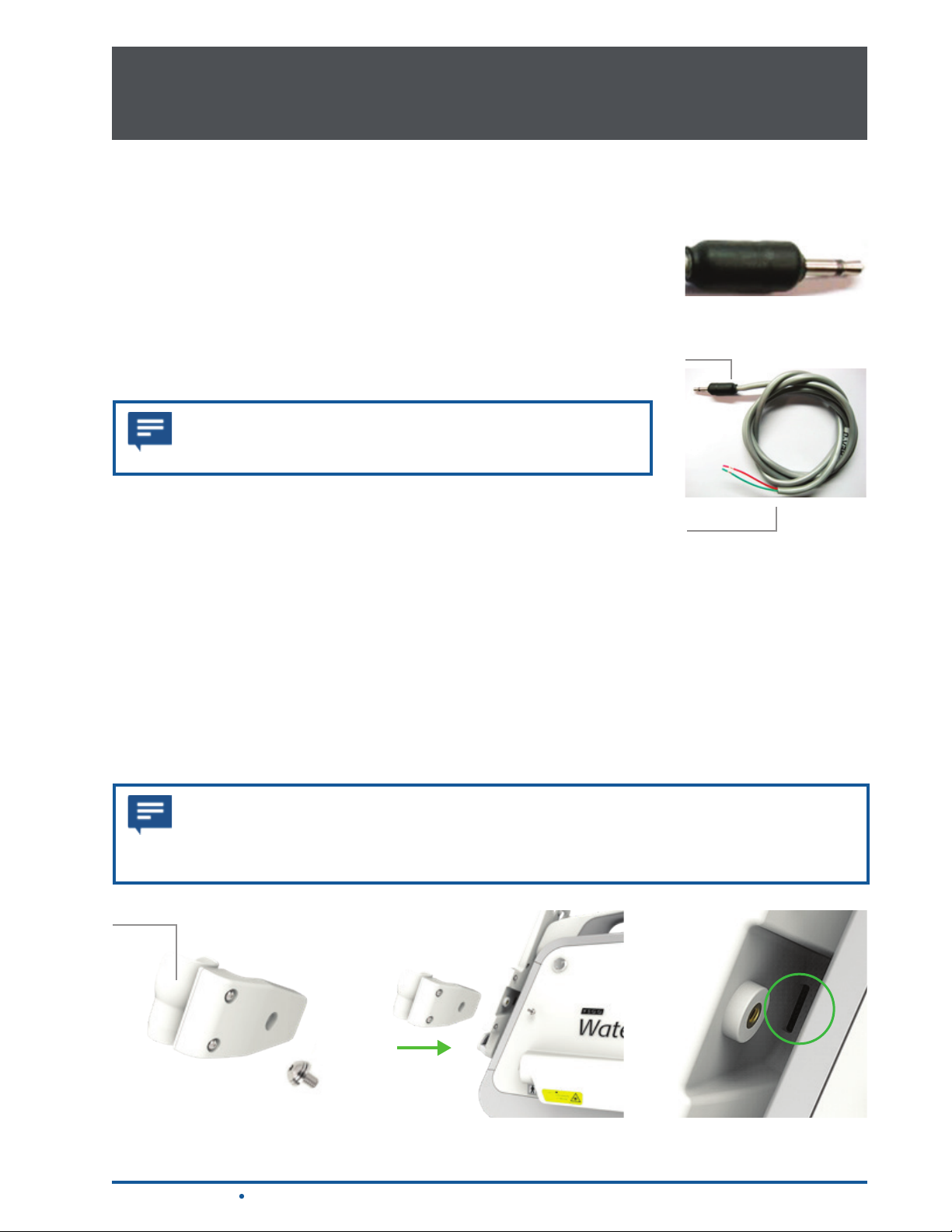
7.3.2 USING THE REMOTE INTERLOCK
The remote interlock is a safeguard designed to protect anyone who might
enter the operatory while the laser is ring without wearing appropriate laser
protection eyewear. To utilize this safety feature, the remote interlock plug
(a) must be wired to a multi-conductor wire and inserted into the rear of the
laser console. The other end of the wire (b) is attached to a door switch/
sensor; if the door is opened, the connection to the switch is deactivated,
immediately stopping the laser from ring. Contact BIOLASE or your
authorized BIOLASE representative with any questions on how to install this
feature.
NOTE: The plug must be installed into the console in order for
the laser to work, whether or not the remote interlock function
is used (Figure 7.1). Cable is not included.
7.3.3 INSTALLING THE HANDPIECE HOLDER
The Handpiece Holder is packaged as a separate item in the system
packaging. Attach it to the Tablet Holder utilizing the smaller of the two
screws and Allen wrenches provided (Figure 7.2):
1. Grip the Handpiece Holder with the cradle facing the same direction as
the Tablet Holder (Figure 7.3).
(a)
(a)
(b)
Figure 7.1
2. Slide the Handpiece Holder into the slot at the back of the Tablet
Holder (Figure 7.4) until the holes in both pieces are aligned.
3. Insert the smaller of the two screws provided into the hole and tighten
with the smaller Allen wrench.
NOTE: The Handpiece Holder can be installed on the left side of the Tablet Holder, if
preferred. To do so, the cradle must be rotated; remove the two screws holding the cradle to
the at surface of the Handpiece Holder, rotate it 180 degrees, then reattach it, again using
Cradle
the two screws.
Figure 7.2
Waterlase Express User Manual
Figure 7.3 Figure 7.4
27

7 Installation and Set-Up7 Installation and Set-Up
7.3.4 INSTALLING THE TABLET
The Tablet is attached to the console by a USB connector incorporated inside the bottom of the control
panel. Holding it parallel to the Tablet Holder, slide the Tablet downward into the Holder/control panel so
that it makes contact with the USB connector, and lock into place by ipping the upper Latch over the
Tablet; tighten the thumbscrew on the back of the Tablet Latch to prevent the Tablet's removal. Once the
Tablet is properly connected and active, the LED indicator on the front of the Tablet Holder/Control Panel
will light up.
The Tablet battery is fully charged prior to shipment. However, if it does not turn on when the power
button on the side of the Tablet is pressed, take the following steps:
1. Remove the Tablet from the Tablet Holder by either pulling up on the upper two corners or pushing
up from the bottom two corners.
2. After connecting the USB cable to the charging adapter, insert it into the Tablet’s USB/accessory
port at the bottom of the Tablet and plug the charging adapter into a standard AC power outlet. It
should take at least 15 minutes to charge the tablet for use on the console. The Tablet will continue
to charge when the console is on. International power adapters are provided for the charging
adapter
3. Remove the USB cable from the Tablet and replace the Tablet in the Tablet Holder.
Tablet Latch
Tablet Holder/
Control Panel
USB Connector
(Inside Holder)
USB/Accessory Port
Power Button
Volume
Figure 7.5
28
NOTE: When installed, the Tablet will charge only when the system is plugged in and ON. If
the system is OFF, the Tablet will not charge.
Waterlase Express User Manual

7 Installation and Set-Up7 Installation and Set-Up
7.3.5 FILLING THE PATIENT WATER BOTTLE
The patient water bottle provides the water supply for the Handpiece spray.
An error message will appear on the screen if the built-in sensor detects the
water level is low, or the bottle empty; ll or replace the water in the patient
water bottle following the steps outlined below:
1. Make sure the system is in Standby mode for at least ve seconds;
this allows the bottle to depressurize.
2. Push the bottle release button on top of the bottle holder and pull the
bottle straight back.
3. Twist the bottle assembly so that the arrow on the cap aligns with
the circle on the base (Figure 7.6); lift the cap off the base.
4. Fill the bottle only with distilled or de-ionized water. DO NOT USE
TAP OR FILTERED WATER.
5. Replace the cap by matching the arrow on the cap to the circle
on the base (Figure 7.6). Twist the cap clockwise until the arrow on
the cap and the arrow on the base are aligned (Figure 7.7).
Figure 7.6
6. Attach the bottle back into its Holder; make sure the connector is
fully engaged.
WARNING: Be careful when handling the patient water bottle; do not drop or knock it against
a hard surface. Even a small crack may cause damage when the bottle is pressurized.
DO NOT USE IF DAMAGED.
NOTE: BIOLASE recommends replacing the patient water bottle every ve years. Refer to
the expiration date noted on the bottle label.
Figure 7.7
Waterlase Express User Manual
29

7 Installation and Set-Up7 Installation and Set-Up
7.3.6 INSTALLING THE FIBER OPTIC CABLE SUPPORT ARM
The Fiber Optic Cable support arm is packaged as a separate item
in the system packaging. If used, attach it to the laser console using
the larger of the two screws and Allen wrenches provided:
1. Remove the triangular plastic plug (Figure 7.8) located on the
console handle behind the Tablet Holder (Figure 7.9).
2. Install the Fiber support base; make sure the hole in the base
aligns with the hole in the console
(Figure 7.10).
3. Place the larger of the two screws supplied, with the lock
washer, into the hole and tighten with the Allen wrench.
4. Insert the ber support arm into the ber support base (Figure
7.11).
Figure 7.8
Figure 7.9
30
Figure 7.10
Figure 7.11
Waterlase Express User Manual

7 Installation and Set-Up7 Installation and Set-Up
7.3.7 CONNECTING THE FIBER OPTIC CABLE
The Fiber Optic Cable dispenses an air/water spray, along with laser radiation, through the Handpiece to
the target tissue.
NOTE: It may help to drape the Fiber Optic Cable around your neck for ease of handling as
you prepare it for installation.
WARNING: Always hold the Fiber Optic Cable by the xed collar connector (below the red
line). Holding and/or twisting the Fiber Optic Cable, or bending it to a diameter less than 4.0
inches can damage it, making it inoperable.
1. Remove the Fiber Optic Cable from its packaging.
2. Remove the protective silver cap from the proximal end of
the ber; this is the connector that attaches to the Waterlase
Express console.
3. Remove the protective cover of the ber shaft at the distal
end and hold the shaft towards any light source; look into
the proximal end of the ber; it should glow yellow, be at,
and clean. Replace the cover.
4. Remove the plastic cover from the laser aperture (do not
lose; save for future use).
5. There is a red dot over the two gold pins on the barrel
connector; keeping these pins oriented to the top of the
connector and slowly insert the long central pin into the laser
aperture so that the red dot above the pins aligns with the
red dot on the aperture (Figure 7.12). Push the connector in
until it is fully engaged by holding it by the collar; do not twist
or force it into place. Turn the locknut clockwise to x the
Fiber Optic Cable snugly in place (Figure 7.13).
WARNING: DO NOT APPLY FORCE when installing
the Fiber Optic Cable. Applying force may damage the
laser head components and Fiber Optic Cable.
6. Remove the protective cover from the distal end of the Fiber
Optic Cable once more and conrm there is no debris on the
window, it is clean and not damaged.
Figure 7.12
Fiber
Connector
Locknut
7. Carefully place the Fiber Optic Cable with its protective
cover, or with the Handpiece connected, in the Handpiece
Holder.
Waterlase Express User Manual
Collar
Figure 7.13
31

7 Installation and Set-Up
7.3.8 INSTALLING THE FIBER OPTIC CABLE RETAINER
The Fiber Optic Cable Retainer is designed to secure the excess length of the Fiber Optic Cable to keep
it clear of the Tablet (Figure 7.14).
1. After connecting the Fiber Optic Cable to the laser console, hold the length of the Fiber straight
out to remove any twisting, then loop it up towards the hook on the Fiber Support Arm; place
the Handpiece into the Handpiece holder and then insert the Fiber into the hook (keep the black
O-ring on the proximal side of the hook.
2. Place the looped portion of the Fiber between the two long tabs of the Cable Retainer (Figure
7.15). Adjust the ber by sliding it through the retainer to create a natural radius (>2.0 inches).
Carefully slide the Cable Retainer onto the space between the Tablet holder and the Handpiece
holder and snap it into place (Figure 7.16).
3. To remove, push the bottom ends of the tabs back to unsnap them from the Tablet holder; pull up
and over. If they do not move easily, press down on the top of the Cable Retainer while pushing
the tabs.
32
Figure 7.15
Figure 7.14
Figure 7.16
Waterlase Express User Manual

7 Installation and Set-Up
7.3.9 CONNECTING/DISCONNECTING THE HANDPIECE TO THE
FIBER OPTIC CABLE
CAUTION: Handpieces are not sterile when sold and MUST be sterilized prior to initial
use, and cleaned and sterilized between patients. Refer to Section 11 for
complete instructions on cleaning and sterilization.
1. Remove the rear plug and the Tip plug from the Handpiece. Be sure to save the plugs, as they will
always be required when preparing the Handpiece for cleaning and sterilization
Tip Plug
2. Hold the Fiber Optic Cable by the connector; remove the ber protective cover from the ber shaft
of the ber by gently, but rmly, pulling it; be sure to save the cover.
Protective Cover
3. Check the ber shaft for any moisture and wipe with a dry, lint free tissue if any is present.
4. Carefully insert the Handpiece onto the ber shaft until it sits rmly against the connector and clicks
into place (do not twist).
Rear Plug
Connector
ConnectorFiber Shaft
Figure 7.17
Fiber Optic Cable
Figure 7.18
Figure 7.19
Figure 7.20
5. To disconnect the Handpiece, hold the Fiber Optic Cable by the connector and gently, but rmly
pull on the Handpiece until it comes completely off the ber shaft. DO NOT apply excessive force.
Figure 7.21
Waterlase Express User Manual
33

7 Installation and Set-Up
7.3.10 INSTALLING AND CHANGING THE TIP IN THE HANDPIECE
A laser tip is installed in the Handpiece to direct the laser energy: based on its shape and length, a tip
will focus that energy differently onto the target tissue.
Tips may be installed using the Revolving Tip Holder, which safely holds/stores up to 6 tips at one time
(Figure 7.22), or the Tip Remover included with the Handpieces (Figures 7.23, 7.24, 7.25).
Always inspect the Tip prior to use as described in Section 12.
DO NOT use if damaged.
1. Place the system into Standby.
2. Remove the Tip Plug from the Handpiece head.
3. The Tip must be sterilized before initial use and between
patients as described in Section 11. If not sterilized in the Tip
Holder, remove the Tip from its sterilization pouch and insert it
into the Tip Holder or the Revolving Tip Holder by aligning the rst
groove of the Tip ferrule against the receiving edges of
the Holder, then sliding the Tip in; using tweezers facilitates
this process.
Figure 7.22
4. Align the Tip orice of the Handpiece over the input end of the Tip
placed in the Tip Holder or Revolving Tip Holder (Figure 7.23).
5. Carefully lower the Handpiece and insert a clean/inspected
Tip all the way until the shoulder of the Tip ferrule sits against
the Handpiece head (Figure 7.24).
6. Slide the Handpiece laterally through the slot, away from the
Tip Holder or Revolving Tip Holder (Figure 7. 25).
WARNING: Never touch the proximal (input) or distal
(output) end of the Tip. If the proximal surface is
contaminated, it may damage the Tip, Handpiece, and
Fiber Optic Cable. Hold the Tip only by the plastic ferrule.
WARNING: Be careful not to hit the proximal (input) end of
the Tip against the Handpiece head and not to break the
remaining ngers of the plastic ferrule.
To remove the Tip, repeat this process in reverse order:
1. Slide the Handpiece laterally through the slot toward the Tip Holder or Revolving Tip Holder.
Figure 7.24
Figure 7.23
Figure 7.25
2. Place your thumb against the selected tip slot to prevent the laser Tip from falling out of the Tip
Holder when disconnecting it from the Handpiece.
34
Waterlase Express User Manual

7 Installation and Set-Up
3. Carefully lift the Handpiece to disengage the tip ferrule from the
Handpiece head.
4. Use tweezers to slide the Tip out from the Tip Holder or
Revolving Tip Holder; discard the used Tip in a medical waste
sharps container.
7.3.11 FIRST TIME START-UP
First time start-up of the Waterlase Express requires the user to follow
a series of steps before initial use:
1. Insert the Tablet in the Tablet Holder: make sure it is turned ON.
2. Turn the power switch at the rear of the console and the
Keyswitch at the front of the console to the ON ( l ) position; the
BIOLASE logo screen will appear, and the system software will
begin to load (approximately 30 seconds).
3. If no communication with the laser is detected by the Tablet, a
screen will appear prompting the user to check that the console
is plugged in, the Keyswitch is turned to the ON ( l ) position, the
power switch is ON, and the Tablet is properly docked
(Figure 7.26).
4. A "Welcome" screen will display a message encouraging the user
to review the User manual for detailed instructions on how to set
up and start the laser. This screen will only appear at rst time
start-up as long as "Do not show this message again" is checked
at this time. Press "Continue" to proceed to the next step.
5. Tap on the blank box; a keyboard will appear. Enter the system
license code (issued at purchase), press continue (Figure 7.27).
6. Enter the doctor’s rst and last name, telephone number, email,
and create a password, as prompted (Figure 7.28).
7. (Optional) Press the Set-Up Wi-Fi button; the system will begin to
scan for Wi-Fi networks.
Figure 7.26
Figure 7.27
8. (Optional) Select a Wi-Fi network, enter the password for the
network selected (Figure 7.29), then press OK (Figure 7.30).
9. Initial set-up is now complete; the system will proceed to the
daily start-up menu prime screen (Figures 7.31, 7.32).
Waterlase Express User Manual
Figure 7.28
35

7 Installation and Set-Up
Figure 7.29
Figure 7.31 Figure 7.32
Figure 7.30
36
Waterlase Express User Manual

7 Installation and Set-Up
7.3.12 ENABLING BIOLASE CONNECT
NOTE: An active wireless connection is necessary to implement this feature on the
Waterlase Express. Wi-Fi may be enabled during rst-time start-up, or at any later time by
going to the main menu and selecting the Wi-Fi option. BIOLASE is not responsible for any
internet connectivity issues; these must be reported to the local internet service provider or
similar support personnel for resolution.
Waterlase Express includes a set of features which allow the user to interact with BIOLASE utilizing
Wi-Fi. These features provide direct contact with Customer Care for clinical and/or technical support,
automated software and content updates, remote access for diagnostic purposes, access to training
tools, courses, and study reports, and participation in an Online forum with other users. However,
no individually identiable patient data of any kind is accessed or stored on the Tablet itself.
BIOLASE Connect may be enabled during rst-time start-up, or at any later time by going to the main
menu and selecting the Wi-Fi option. An active wireless connection is necessary to implement this
feature on the Waterlase Express.
NOTE: To contact BIOLASE for technical or clinical assistance, simply press the Call
Customer Care button located on the bottom right of most screens. This will automatically
generate an email request to BIOLASE Customer Care; a representative will respond via
phone as soon as possible (within business hours).
Waterlase Express User Manual
37

8 Operating Instructions
WARNING: Post the laser warning sign provided with the laser system outside the operatory
when the laser is in use. Anyone entering the room must put on appropriate laser protection
eyewear before going in. Doctor, patient, assistant, and all others inside the operatory must
wear appropriate laser protection eyewear for the 2780 nm wavelength (OD 3 or greater) at all
times when the laser is active. Prior to use, always inspect eyewear for pitting and cracking.
Replace if damaged.
WARNING: Use of controls or adjustments, or performing procedures other than those
specied in this user manual may result in hazardous radiation exposure.
8.1 OVERVIEW
Before using the Waterlase Express be sure the laser has been installed properly, as described in
Section 7 of this user manual, to ensure safe and efcient functionality.
8.2 TABLET HOLDER - FUNCTION CONTROL BUTTON AND
LED INDICATORS
The function control button, located in the center of the Tablet Holder, activates the controls and display,
and is used to place the system into Ready (green), Standby (amber), or Sleep mode.
Status Indicator
Tablet Connectivity Indicator
There are two LED indicators on either side of the function control button to indicate the Tablet
is connected and to conrm the wireless connection to the Footswitch is active; the Footswitch
Connectivity Indicator will only light up when the Footswitch and Laser are actively communicating, i.e.,
the Footswitch is pressed.
NOTE: Ready (green) mode: The laser is active and prepared to re once the Footswitch is
pressed. The laser will only re while in Ready mode. Laser will revert to Standby (amber)
mode after 10 minutes of inactivity. When the green LED is ashing, the laser is ring.
Standby mode: The laser is powered but not operable. To operate (re), the laser must be in
Ready mode.
Wireless Footswitch
Connectivity Indicator
Function Control Button
Figure 8.1
38
Sleep mode: The laser will go to sleep after 10 minutes of inactivity while in Standby mode
to conserve energy, or by pressing the Function Control button for 3 seconds before releasing;
the light around the button will go off. To take the system from Sleep mode to
Standby mode, press and hold the Function Control button again for 3 seconds.
Waterlase Express User Manual

8 Operating Instructions
8.3 DAILY START-UP
1. Power up the Tablet. Verify that all connections have been properly secured; turn the main power
switch at the back of the console ON ( I ); insert the key into the Keyswitch and rotate it clockwise
to the ON ( I ) position. The LED light on the Tablet Holder lights up when the Tablet is properly
powered on and docked in the Tablet Holder, connected and active (if the power switch and
Keyswitch are not both ON, the LEDs will not light up.)
2. Make sure the air supply is connected and verify that the patient water bottle is no less than ⅓ full
with distilled or de-ionized water. It is suggested to completely ll the patient water bottle at the start
of the day.
8.3.1 INITIATING THE LASER FROM OFF STATUS
• Turn the main power switch at the back of the console ON ( I ) (when the power switch is OFF, LEDs
will not light up); insert the key into the Keyswitch and rotate it clockwise to the ON ( I ) position
• Press and hold the power switch on the right side of the Tablet to turn it on
• The startup screen will appear, and the system software will begin to load (approximately
30 seconds)
• Verify that the Footswitch and laser are paired (See Section 12.9)
• Attach the Handpiece to the Fiber Optic Cable (See Section 7.3.9)
• Ensure the tablet is properly docked in the Tablet Holder and secured with the Tablet Latch; if the
Tablet is not properly docked, the screen will stay xed and the tablet indicator light on the control
panel will not light up. However, if the Tablet is docked correctly but cannot communicate with the
laser, the error message "Tablet Communication Error" will appear on the tablet screen; restart both
the laser and the tablet.
• All users congured to the system listed on the User selection screen; select the proper account. If
the system is congured to only one user, this screen will not be displayed (Figure 8.2)
• A screen will appear giving
the user the option to prime
the Handpiece or skip this
step (if the Handpiece is
already primed). If "prime"
is chosen, a message will
appear conrming that
priming is taking place
(approximately 6 seconds)
(Figure 8.3)
Waterlase Express User Manual
Figure 8.2
Figure 8.3
39

8 Operating Instructions
NOTE: The Handpiece must be primed during setup; priming forces water from the patient
water bottle to the Handpiece. If priming does not take place, no water will spray from the
Handpiece during the procedure. Conversely, the Handpiece should be purged at the end of
the day.
To avoid damaging the laser console or Tablet, do not point the Handpiece towards either
one during priming, as water will come out of the Handpiece head.
After priming, set-up is complete; the system will now transition to the home (Procedure) screen in
Standby mode.
8.3.2 WAKING THE SYSTEM FROM SLEEP MODE
When the laser system is not shut OFF (O) at the power switch, the laser and Tablet will go into Sleep
mode (Tablet will be blank) after 10 minutes of inactivity when in Standby mode. The system can also
be placed into Sleep mode by pressing and holding the function control button for three seconds.
To “wake” the system:
• Press and hold the Function Control Button on the center of the control panel for three seconds
• Press the power button on the side of the Tablet
CAUTION: Make sure the Handpiece is stored in the Handpiece Holder whenever the laser
system is powering up or waking from Sleep state.
8.4 ACTIVATING THE WATERLASE EXPRESS
Place the system into Ready mode after selecting a procedure by pressing the Function Control Button
on the Tablet Holder; wait approximately 2 seconds, then press down on the Footswitch when ready to
re the laser.
NOTE: Approximately 2 seconds will elapse between the time the Footswitch is pressed and
the laser actually res. This delay is designed to help prevent the unintentional activation of
the laser.
40
Waterlase Express User Manual

8 Operating Instructions
8.5 TURNING THE WATERLASE EXPRESS OFF
While it is not necessary to turn the laser OFF at the end of the day, it is best practice to do so. If the
system is not turned OFF, the Tablet will go dark after a period of no activity.
1. Press the logout icon at the bottom of the home screen (Figure 8.4).
2. A screen will appear offering to Switch User or Turn Off/Purge; select "purge" and wait for the
process to complete (Figure 8.5).
3. Disconnect the Handpiece and Tip. Dispose of the Tip in a medical waste sharps container.
4. Turn the key counterclockwise to the OFF (O) position.
5. Turn the power switch to the OFF (O) position.
6. Turn the Tablet off by pressing the power button on the side of the Tablet (optional).
NOTE: When the system power is OFF, the Tablet battery will not charge; the Tablet battery
charges only when the system is ON. Always turn the Tablet off at the end of the day to
conserve its battery charge.
Waterlase Express User Manual
Figure 8.4 Figure 8.5
41

9 User Interface
The graphical user interface (GUI) is the main part of the system control. It communicates with the user
through the interactive Tablet screen display and is designed to provide easy and intuitive interaction
with the laser system while performing clinical procedures. Buttons on each screen allow easy
navigation of the GUI.
9.1 ICONS-DEFINITION
RESTORATIVE PROCEDURES
SOFT-TISSUE PROCEDURES ENDO PROCEDURES
PERIO PROCEDURES FAVORITES
MENU
System menu
ILLUMINATION
(White light)
LASER ENERGY AIR
HOME
Return to Procedures main menu
VIDEOS and ANIMATION
Access animation of procedure/step
TURN OFF/PURGE PRIME/PURGE
IMPLANT PROCEDURES
AIMING BEAM
(Red light)
WATER
LEARN
User Manual
CALL CUSTOMER CARE
Contact BIOLASE customer care
42
BACK
Back to previous screen
STEP UP
Increase settings for air/water/
illumination/aiming beam/laser power/pulse rate
FAVORITES
Save procedure/settings to favorites
DOCTOR CREDENTIALS
DEFAULT SETTINGS PULSE PER SECOND
FORWARD
Advance to next screen
STEP DOWN
Decrease settings for air/water/
illumination/aiming beam/laser power/pulse rate
HANDPIECE
Handpiece selection
TIP
Tip selection
Waterlase Express User Manual

9 User Interface
PULSE ENERGY
LOCKED
Modied settings are saved
PULL DOWN/UP
When pressed, displays/hides
additional controls
CLINICAL CALL
Identies the CALL as clinical and
directs it to BIOLASE customer care
REMOTE ACCESS SUPPORT
When pressed by the user, allows BIOLASE
Tech support to access the laser system for
problem diagnosis/resolution
SETTINGS RETURN TO PROCEDURE
BATTERY STATUS LOW BATTERY CHARGING
UNLOCKED
Settings are modied but not saved
LOGOUT
OR CHANGE USER
TAB FORWARD OR BACK
Allows going back one screen
or forward one screen
TECHNICIAN CALL
Identies the CALL as technical and
directs it to a BIOLASE service technician
SAVE
OFFLINE
Tablet is not connected to the laser system
WEB PORTAL LEARNING CENTER
SETTINGS SYSTEM INFORMATION
MAINTENANCE SESSION REVIEW
LASER STATUS INDICATOR
Bottom of screen –
Gray = Laser/Tablet not connected
LASER STATUS INDICATOR
Bottom of screen –
Amber = Laser in Standby
Place the Tablet
in the Tablet Holder
Turn the Keyswitch to the ON position Check the laser system is plugged in
Turn the power switch to the ON position (I)
STATUS CONNECTION
Tablet is connected to the laser system
LASER STATUS INDICATOR
Bottom of screen –
Green = Laser is Ready
LASER STATUS INDICATOR
Bottom of screen –
Red = Laser is ring
Check Tablet is properly coupled to
USB connector
Wi-Fi connected.
Wi-Fi is
not connected.
Waterlase Express
User Manual
43

9 User Interface
9.2 MAIN MENU
Press the MENU button at the bottom of any screen to access a number of key features included with
the Waterlase Express (Figure 9.1). To return to the menu at any time from any procedure screen, press
the MENU button.
9.2.1 LEARNING CENTER
Within this selection the user is offered six options (Figure 9.2):
• Best practices (grouped by procedure)
• News (current industry news, articles)
• Marketing help (current marketing articles and content)
• Training and education (opportunity for learning new procedures, online training, classroom
training schedules, short biographies of BIOLASE educators, and upcoming events)
• White papers (grouped by procedure, research, and clinical)
• Videos and animation (grouped by procedure)
Return to Procedure
Main Menu Button
44
Figure 9.1
Go Back Button
Figure 9.2
Waterlase Express User Manual

9 User Interface
9.2.2 SETTINGS
This category allows the user to personalize the laser system in the following areas (Figure 9.3):
• Initial Setup (rst-time start-up)
• Modes (choice of Basic or Advanced*)
• User (rename user, add user, clear user, delete user, or restore user data)
• Language
• Wi-Fi (enable Wi-Fi, change network, disable Wi-Fi)
• Footswitch Pairing
*Requires the completion of a BIOLASE-sponsored training course to access.
9.2.3 SYSTEM INFORMATION
System Information provides the user with the following data (Figure 9.4):
• Specications (system specications and icon glossary)
• Memory
• Software Versions
• Applications
• License Code
• Set Date and Time
Waterlase Express User Manual
Learn Button Call Customer Care Button
Figure 9.3
Figure 9.4
45

9 User Interface
9.2.4 MAINTENANCE
The Maintenance selection offers the user six options (Figure 9.5):
• Handpiece and Tips
• Purge/prime (starts the purge/prime process)
• Footswitch battery
• Daily
• Service
• System log
In addition, the Remote Access Button, when activated, allows BIOLASE Service to provide remote
access support in real time.
9.2.5 SESSION REVIEW
Waterlase Express stores all session information (Figure 9.6), including procedure settings and duration,
and allows the user to sort by:
• Date
• Procedure
• Doctor
Review
Categories
Remote Access
Button
46
Figure 9.5
Figure 9.6
Waterlase Express User Manual

9 User Interface
NOTE: No patient information is stored in the laser software.
9.2.6 WEB PORTAL
This selection offers the user four choices (Figure 9.7), each accessible only if Wi-Fi is enabled:
• Breaking news (displays a list of latest news items to choose from)
• Discussion forum
• BIOLASE Home
• BIOLASE Store
Return Home
(Procedures Main) Screen
Waterlase Express User Manual
Figure 9.7
47

9 User Interface
9.3 HOME (PROCEDURES MAIN) SCREEN
The Home screen displays 6 procedure categories (Figure 9.8):
• Restorative
• Perio
• Endo
• For each category, the screen will display a selection menu for that option, offering a choice of up
to six procedures (Figure 9.9)
• Once a procedure is selected, the procedure step screen is displayed (Figure 9.10). Choose the
desired step to begin the procedure
• A Tip Selection screen appears highlighting the Tip most appropriate for that step, as well as any
acceptable alternatives, if there are any (Figure 9.11). After changing the Tip, conrm by pressing the
image of the tip installed.
• If changing handpieces, press the Handpiece Selection icon at the bottom of the Tip Selection
screen. An image of the recommended Handpiece will appear. Press the image of the Handpiece
chosen; the system will purge. Change the Handpiece, then begin the priming process by pressing
the prime icon. Once completed, the Handpiece will be ready to use.
NOTE: The Tip selection screen may also be accessed by pressing the Tip selection icon
on the lower left of the screen. To exit the screen, a Tip must be selected. If the procedure
or step has been chosen in error, a tip must still be selected to exit the screen. After
exiting, choose the procedure or step desired. The previous choice of Tip, if different, will
automatically be superseded.
• Soft-tissue
• Implant
• Favorites
48
Figure 9.8
Figure 9.9
Figure 9.10
Waterlase Express User Manual

9 User Interface
• Settings have been pre-programmed at the factory for each step and are displayed in the center
of the screen. The user may modify these settings within a set minimum and maximum range, as
needed, by sliding the bar at the bottom of the page to the right or left (Figure 9.12)
NOTE: The bar will only move within a prescribed range regulated by the number of settings
pre-set for the procedure step. For example, if only one setting is designated for the step, the
bar will not move; if two settings are designated, the bar will only move from one to the other,
with no settings in-between the two.
• Pressing and holding a step allows the modied setting to be saved, cleared, or saved to favorites
(Figure 9.13)
• Save makes the modied setting the default for that step and displays a “lock” icon on the step
(Figure 9.15), replacing the “star” icon (Figure 9.14)
• Save to Favorites saves the “new” step values to the selected favorites slot
• Clear restores the factory default setting
• Press the control button on the Tablet control panel to transition from Standby to Ready mode,
then press the Footswitch to re the laser
• Continue through each step until the procedure is nished. Press the HOME icon return to the
Procedure screen to prepare for the next patient
NOTE: The Standby/Ready/Firing indicator at the bottom of the Tablet screen is not a button.
To change the status of the laser, use the control button on the control panel.
Figure 9.11
Waterlase Express User Manual
Figure 9.12
Figure 9.13
49

9 User Interface
9.4 FAVORITES
The Waterlase Express has the capacity to store up to 12 favorite procedure or step settings. To access
settings stored as Favorites, choose the Favorites category on the Procedures Home screen.
9.4.1 CREATE A FAVORITE
Anytime a preset is modied, the star symbol that appears in the step selection segment changes to an
unlocked lock. (Figure 9.14, 9.15)
Figure 9.14
To save the changed settings as a Favorite, press the Favorites (heart) icon on the bottom right of the
screen.
1. Choose any one of the slots available to save the modied settings as a Favorite (Figure 9.16)
2. Name the Favorite (Figure 9.17)
3. The name will appear in the chosen slot on the Favorites screen (Figure 9.18)
Figure 9.15
50
Figure 9.16
Figure 9.17
Figure 9.18
Waterlase Express User Manual

9 User Interface
9.4.2 RENAME OR DELETE A FAVORITE
• Select Favorites on the Home screen to access personalized settings (Figure 9.18)
• Press and hold the favorite chosen for approximately 2 seconds (Figure 9.16)
• Options to either “Rename” or “Delete” the favorite will be displayed (Figure 9.17)
• If “Rename” is pressed, a screen with a keyboard will appear; type in the new name for the favorite,
then press Enter
• The Favorites screen will reappear and the new name will be displayed
• If “Delete” is pressed, a message will appear conrming the selected favorite has been deleted
NOTE: The user may also just "lock" in a setting for a step by pressing the open lock on the
step selection segment (Figure 9.15) and then choosing Save (Figure 9.13); the open lock
will change to a locked lock. This new setting will become the standard setting for this step
unless/until the factory presets are re-established through the Factory Reset option in the
Main Menu (Settings).
9.4.3 ADJUSTING THE HANDPIECE, AIMING BEAM, AND ILLUMINATION
To change the brightness of the Handpiece illumination (white light) or aiming beam (red light):
• Touch the pull down icon at the top of the screen (Figure 9.19)
• Adjust each element to the desired level (Figure 9.20)
• Touch the pull up icon at the bottom of the screen to return to the Procedure screen (Figure 9.20)
Waterlase Express User Manual
Figure 9.19
Figure 9.20
51

9 User Interface
9.5 PRESETS
The settings chosen for a procedure will contribute to its overall success. Waterlase Express uses a
spray combining air and water to effectively cut tissue, in conjunction with pulse repetition rate and
mode, and must be balanced appropriately in order to obtain optimal clinical outcomes and positive
patient results.
As examples, a greater percentage of water is good for cooling targeted tissue, but too much water
will reduce the power delivered because the laser radiation is absorbed by water; more air in the mix
will generate a ner spray, making it easier for the water molecules to penetrate the tissue, facilitating
cutting; a higher pulse repetition rate will allow faster, smoother cutting of hard tissue, but could result in
a higher tissue temperature, possibly making the procedure more painful for the patient, while a longer
pulse (S mode) works well for soft tissue because it increases tissue temperature, reducing bleeding.
Recommended settings for each procedure/step have been pre-programmed into the Waterlase
Express at the factory. These may be modied within a limited range by sliding the bar at the bottom
of the screen to the right or left. Always use clinical judgment when making adjustments to power,
water, air, pulse repetition rate, and mode as may be necessary to compensate for variations in tissue
composition, density and/or thickness.
NOTE: Any combination of customized values that prove particularly effective in a specic
procedure may be saved to favorites.
9.6 BASIC MODE
Basic is the default mode of the Waterlase Express. It provides access to most of the applications
within the main categories and utilizes a pre-dened range of parameters for each. These settings may
only be adjusted within a set minimum and maximum range.
9.7 ADVANCED MODE
Advanced mode allows the user to modify each of the settings (energy, pulse per second, air, and
water) individually for a procedure, within established parameters. The code that "unlocks" this mode is
only provided once the user has completed initial classroom and hands-on training. Contact BIOLASE
Customer Care for the individualized code, which is unique to a specic system and will not work with
any other Waterlase Express.
NOTE: Some procedures require at least minimal air or water. In these cases, although the
slider can be moved to lower the air or water settings to "0," thus effectively shutting off the
air/water spray, the procedure settings will never stay at "0," but will always revert to the
minimum air/water values appropriate for the procedure.
52
Waterlase Express User Manual

9 User Interface
9.7.1 ACCESSING ADVANCED MODE
To enter Advanced mode:
1. Go to the main menu.
2. Select Settings, then Modes.
3. Press Advanced.
4. Enter the customized code issued by BIOLASE Customer Care and press continue.
5. Return to the Procedure Home screen by pressing the home button.
6. Choose the desired procedure category and proceed as outlined in Section 9.3.
7. A Tip Selection screen appears highlighting the tip most appropriate for that step, as well as any
possible alternatives, if there are any (Figure 9.21). Conrm the tip selected before proceeding by
pressing the tip image chosen. Purge/prime as needed.
8. On the procedure screen, touch the pull down icon at the top of the screen to open the advanced
settings display (Figure 9.22).
9. Adjust the settings for the procedure as needed, then touch the pull up icon at the bottom of the
screen to return to the procedure (Figure 9.22). The modied settings will appear in the center of
the screen (Figure 9.23).
NOTE: To contact BIOLASE for technical or clinical assistance, simply press the call
customer care button located on the bottom right of most screens. This will automatically
generate an email request to BIOLASE Customer Care; a representative will respond via
phone as soon as possible (within business hours).
The Main menu may be accessed at any time from a procedure screen by pressing the System Menu
icon at the bottom left of the screen (Figure 9.24). To return to the procedure from the Main menu,
simply press the icon at the upper right hand corner of the screen (Figure 9.25).
Waterlase Express User Manual
Figure 9.21
Figure 9.22
53

9 User Interface
Pull Down Icon
Figure 9.23
Figure 9.25
Figure 9.23
Figure 9.23
Figure 9.24
9.7.2 SOFTWARE/FIRMWARE/CONTENT UPDATES
From time to time BIOLASE will update the Waterlase Express system Software and/or Firmware, or
refresh the content of the Learning Center, adding new videos, animations, white papers, etc.
All users will be notied of upcoming updates, along with a summary of the enhancements included with
each update.
Users who are utilizing BIOLASE Connect will be able to execute updates through their Wi-Fi
connection. The tablet screen will display easy-to-follow step-by-step instructions throughout the
implementation process.
For systems that have not enabled the Wi-Fi feature, one or more SD cards will be provided via mail,
along with detailed instructions.
NOTE: Software updates will take 30 seconds to one minute to upload, but Firmware
will take approximately 20-25 minutes. Contact BIOLASE or your authorized BIOLASE
representative directly for assistance, if needed.
54
Waterlase Express User Manual

9 User Interface
9.8 SYSTEM FLOW CHART
Best Practices
News
Learning
Center
Settings
System
Information
Marketing Help
Training & Education
White Papers
Video & Animation
Initial Setup
Basic
Modes
Advanced
User
Language
Wi-Fi
Footswitch Pairing
Specications
Memory
Software Versions
Applications
Main Menu
Maintenance
Session
Review
Web
Portal
License Code
Set date & Time
Purge/Prime
Service
Daily
System Log
Handpieces and Tips
Footswitch Battery
Select Session
Breaking News
Discussion Forum
BIOLASE Home
BIOLASE Store
Figure 9.26
Waterlase Express User Manual
55

10 Cutting Tissue
The Waterlase Express laser is designed to cut and remove hard- and soft-tissues. Cutting is achieved
in a contact or non-contact mode by application of direct laser energy either with water for cooling and
hydration, or without water for coagulation. It helps to understand the unique nature of the Waterlase
Express laser in order to efciently remove tissues. Waterlase Express operates unlike traditional
medical instruments or devices, and a proper technique must be practiced and perfected to ensure
efcient operation.
BIOLASE recommends anyone using Waterlase Express study this section carefully, practice on tissue
models, and attend a company-sponsored training seminar before using this laser in a clinical situation.
10.1 HARD-TISSUE CUTTING
Hard-tissue cutting is achieved through the removal of tissue with laser-energized water.
1. Select the desired procedure from the Home (Procedures Main) screen (Section 9).
2. Begin the procedure with Step 1; the optimum settings for each step of each procedure have been
preset at the factory.
3. Point the Tip away from the patient and laser system, and step on the Footswitch. You will see
water spray ow from the Handpiece and hear a gentle “popping” sound.
4. If the water ow and “popping” sound are both present, stop ring the laser and move the
Handpiece Tip to the targeted tissue site. Press on the Footswitch to re the laser and begin
cutting tissue.
CAUTION: If no water spray or distinct popping sound is present, stop the laser
immediately and prime the Handpiece. If priming does not result in water spray, refer to the
troubleshooting section of this manual for instructions, or call your authorized BIOLASE
representative for assistance.
5. Use high speed suction as necessary to keep the eld clear. There is a pronounced difference in
cutting techniques between a traditional dental drill and Waterlase Express; it is very important to
have the exact treatment location visually identied before and during the procedure.
6. Maintain a distance of 0.1 to 1.5 mm between the tip and the tissue being treated while moving the
Handpiece over the tissue surface as required.
7. Cutting speed is determined primarily by parameter settings and distance from tissue, not by rapid
hand movement as with the high-speed drill.
8. Gently and slowly move the Handpiece in a circular, brushing, or in-and-out motion, as required,
to remove desired tissues or materials. Do not leave the tip stationary over one spot as it may
cause the patient pain or discomfort. Unlike with traditional dental instruments, with the Waterlase
Express the slower you move the Handpiece Tip the quicker you will remove tissue.
9. Once treatment is completed, release the Footswitch and remove the Handpiece from the
patient’s mouth. Be careful not to hit the Handpiece Tip against teeth or other instruments, or
the tip may break.
56
Waterlase Express User Manual

10 Cutting Tissue
10. To remove the Tip from the Handpiece, use the Tip Holder; place a new Tip in the Handpiece as
described in Section 7. If it’s not immediately needed, use the Tip Plug to avoid contamination and
damage to the Handpiece until it can be cleaned and sterilized for the next patient.
11. Clean, disinfect, and then sterilize the Handpiece, as outlined in Section 11.
12. Disposable, single-use tips, i.e., quartz (glass), must be disposed of in a biohazard medical
waste sharps container. Single-use Tips should not be reused.
Cutting efciency will vary depending upon the power setting, tip diameter, and spray conguration. If
the system appears to be working slowly at the preset power setting, the air and water spray settings
can be adjusted; tap the pull down arrow at the top of the screen and then use the sliders to increase
or decrease the air and water values as needed. Note that clinical efciency depends on power as well
as spray; with experience, the user will be able to gauge spray and power efciency from the sound of
the popping water droplets. A sharper, more distinct popping sound represents a higher cutting rate.
Use your clinical judgment to adjust the air and water spray to compensate for variations in tissue
composition, density and/or thickness.
10.2 SOFT-TISSUE CUTTING
Soft-tissue procedures are performed with direct laser energy, either with or without water spray.
A. Select the desired procedure from the Home (Procedures Main) screen.
B. Begin the procedure with Step 1; the optimum settings for each step of each procedure have
been preset at the factory.
C. Carefully place the tip approximately 1-2 mm from the targeted tissue.
D. Step on the Footswitch and slowly move the tip along the tissue surface. The incision will be
noticed immediately after laser activation.
NOTE: Bleeding is controlled through a reduction in water. The most effective hemostasis is
achieved when the water spray is eliminated completely.
STEP 1—CLEANING PROCESS (HANDPIECE, TIPS)
The cleaning process is intended to remove blood, protein and other potential contaminants, as well as
to reduce the quantity of particles, microorganisms and pathogens present from the Handpiece, laser
Waterlase Express User Manual
57

11 Cleaning, Disinfection, and Sterilization
CAUTION: Handpieces and laser tips are not sterile when sold and must be sterilized prior
to initial use, and cleaned and sterilized between patients. Cleaning must be
performed within a maximum of 1 hour after the procedure and prior to sterilization.
Single-use tips, i.e., quartz (glass), as marked on the packaging, are intended for one-time
use only and must be discarded after use in a biohazard medical waste sharps container.
Use only the MANUAL cleaning process described below. Other cleaning methods should be
avoided since water may damage the ber optics inside the Handpiece.
CAUTION: The Fiber Optic Cable cannot be autoclaved; doing so will make it unusable.
However, the Fiber Optic Cable must always be disinfected between patients by following the
procedure outlined in Step 3 of this section.
Tip surfaces and crevices. Cleaning should be performed prior to sterilization and must be conducted
only by qualied personnel trained in the process who know how to handle the laser Handpiece. Wear
protective gloves when handling the contaminated delivery system.
1. After each clinical procedure, detach the Handpiece from the ber with the Tip still attached. Do
not remove the Tip.
2. Insert the rear plug into the Handpiece; during the cleaning procedure ensure the
cleaning solution and rinse water does not enter the interior of the Handpiece.
3. Rinse the Handpiece with the Tip still installed under lukewarm water (22 – 43°C) for 10 seconds
to remove gross soil.
4. Prepare a cleaning solution per the manufacturer’s instructions. Use a commercially available
surgical instrument detergent/enzymatic cleaning solution with a pH of 7.0, such as Enzol® or
similar enzymatic presoak and cleaner. Follow instructions for the disposal of used solution.
5. Soak a piece of gauze large enough to wrap the Handpiece in the cleaning solution. Squeeze
out the excess liquid and wrap the Handpiece with the Tip still installed and leave wrapped for a
minimum of 10 minutes.
6. Unwrap the Handpiece and Tip. Using a soft-bristled brush dipped in the cleaning solution, gently
brush around the Tip ferrule, crevices, and other hard-to-clean areas for 15 seconds. The brush
should be wet, but not dripping.
7. Rinse the Handpiece under lukewarm running tap water (22-43°C) for 10 seconds.
8. Dry the Handpiece with a lint-free cloth.
9. Visually inspect the Handpiece for any residual soil. If any is still present, repeat steps 5 through 8
until any residual soil is removed.
10. Using the Tip Holder or Revolving Tip Holder, remove the Tip from the Handpiece:
A. Slide the Handpiece laterally toward the Tip Holder or Revolving Tip Holder (Figure 11.1).
58
Waterlase Express User Manual

11 Cleaning, Disinfection, and Sterilization
B. Place your thumb against the selected Tip slot to prevent laser
Tip from falling out of the Tip Holder when disconnecting it from
the Handpiece.
C. Carefully lift the Handpiece to disengage the Tip ferrule from
the Handpiece head (Figure 11.2).
D. Use tweezers to slide the Tip out from the Tip Holder or
Revolving Tip Holder; dispose of the used Tip in a medical waste
sharps container.
11. Gently wipe the orice of the Handpiece head with a dry lint-free cloth,
making sure to remove any soil/debris that may have accumulated in
the crevice between the laser Tip and the Handpiece.
12. Once removed from the Handpiece, single-use Tips must be disposed
of in a biohazard medical waste sharps container; if the Tip is meant to
be reusable, rinse with distilled, or sterile water for 10 seconds and then
dry with a lint-free cloth. Sterilize per the procedure outlined below.
Figure 11.1
Figure 11.2
13. Visually inspect the Tip for any residual soil; if any is present, repeat
step 12 until all residual soil is removed.
STEP 2—STERILIZATION PROCESS
The steam sterilization process is intended to destroy infectious
microorganisms and pathogens.
NOTE: Always perform this procedure immediately after cleaning and prior to use; only use
FDA-cleared (USA) or CE-marked (Europe) sterilization accessories, i.e., sterilization pouch
and autoclave tray. The product packaging is NOT suitable for steam sterilization.
1. Prior to sterilization, remove the Rear and Tip Plugs, if installed. It is also recommended to remove
the mirror from the Handpiece before proceeding (See Section 12.6.1).
2. Place the Handpiece inside a single-wrap, self-sealed pouch.
3. Reusable tips may be autoclaved in the Tip Holder or Revolving Tip Holder. Place the individual
Tips, or the Tip Holder or Revolving Tip Holder loaded with Tips, inside a separate single-wrap
self-sealed pouch.
4. Place the pouches on an autoclave tray. Take care when handling the Handpiece and Tip(s).
5. Do not stack other instruments on top of the pouches.
6. Place the tray into the autoclave chamber and set appropriate cycle, as noted in (Figure 11.3).
7. Upon completion of the cycle, the Handpiece and tips must remain in the sterilization pouches until
used to ensure sterility.
Waterlase Express User Manual
59

11 Cleaning, Disinfection, and Sterilization
Type of Sterilizer Temperature Min Time Drying Time
Gravity Displacement 132°C (270°F) 15 minutes 15 - 30 minutes
132°C (270°F) 4 minutes 20 minutes
Dynamic-Air-Removal
(Pre-Vacuum)
134°C (273°F) 3 minutes 20 minutes
Figure 11.3
8. To reassemble the Handpiece, insert the ber shaft of the ber into the Handpiece until it “clicks”
into place and is secure. To insert a tip, remove the tip from the sterilization pouch with tweezers
and place it into the Tip Holder or Revolving Tip Holder (if not already in the Tip Holder), then
follow the instructions outlined in Section 7.
NOTE: When handling, always hold a tip by the plastic ferrule to avoid damaging the ber;
use of damaged or worn Tips may cause damage to the cable and will compromise the
clinical performance of the Waterlase Express laser system.
STEP 3—DISINFECTING THE FIBER
Always disinfect the Fiber Optic Cable between patients by wiping it completely with an appropriate
disinfecting solution such as Cavicide™ or a similar quaternary ammonium compound product
(containing 20% alcohol or less), and follow the manufacturer’s instructions. DO NOT AUTOCLAVE.
60
Waterlase Express User Manual

12 Maintenance
12.1 DAILY CARE OF THE TABLET AND CONSOLE
Use the adhesive-backed Tablet protective covers provided (p/n 7250003) to protect the Tablet. Be sure
to cover the Tablet, wrap the top of the protective cover around the Tablet Latch and drape the bottom
over the control panel. If necessary, use a lightly pre-moistened lens cleaning wipe or equivalent to
clean any residue or dirt from the Tablet. DO NOT use soap, water, chemicals containing
ammonia, bleach, alcohol, or abrasive cleaners.
A standard disinfectant, such as Cavicide, can be used to wipe down the laser console; however,
DO NOT use bleach or abrasive cleaners.
12.2 ANNUAL MAINTENANCE
The Waterlase Express should be serviced annually only by a qualied, trained, and certied BIOLASE
technician to keep the product in compliance with its specications. Any attempt to perform maintenance
by anyone other than an authorized BIOLASE technician may lead to exposure to laser radiation and
collateral radiation. During the service visit the eld service engineer will fully inspect the system and all
relevant electronic circuits will be calibrated, and lters and cooling uid will be changed. Please contact
your local representative to discuss extended service contracts and annual maintenance options.
12.3 SERVICE AND CALIBRATION
Calibration requires specialized equipment, and is to be performed only by a BIOLASE-trained
technician who is provided with the proper training, calibration procedure, and necessary circuit
diagrams, component parts list, descriptions, etc.
Power calibration is to be performed annually. A calibration log is maintained within the laser system
software, and may be accessed through the maintenance segment of the system menu.
12.4 TIP INSPECTION
CAUTION: Use of damaged or contaminated tips may damage the Fiber Optic Cable and
will compromise clinical performance of the laser. Tips can be inspected using magnifying
lenses, a microscope, the laser aiming beam, or the Tip inspection kit included with the
Waterlase Express Laser System.
Prior to each use always check both ends of the Tip for damage or contamination before
inserting it into the Handpiece.
Check that both ends of the Tip appear at and present a mirror-like reection of any light source. Look
for chips or nicks along the edges of the Tip (Figure 12.6).
Waterlase Express User Manual
6161

12 Maintenance
12.4.1 TIP INSPECTION INSTRUCTIONS
(USING THE TIP CLEANING AND INSPECTION KIT)
1. Remove the Tip from the Handpiece or its packaging and insert
it into the correct side of the Tip test holder using the Tip Holder
(Figure 12.1).
2. Insert the Tip test holder into the test adapter with the distal
(laser-emitting) end of the Tip toward the microscope (Figure
12.2).
3. Slide the adapter over the microscope to move the Tip surface
toward the focal point of the microscope. The focal point lies
in the plane at the end of the clear end tube of the microscope
(Figure 12.3).
4. Turn on the microscope’s built-in light by gently pulling apart the
upper and lower tubes, or hold it up to another light source, and
bring the surface of the Tip into focus using the thumb wheel.
Examine the Tip surface carefully for damage or contamination
(Figure 12.3).
5. To examine the proximal (Fiber) end of the Tip, remove the
adapter from the microscope and gently t the other side of the
test holder into the clear end tube of the microscope (Figure
12.4). Refocus the microscope.
Tip Holder
With Tip Inside
Figure 12.1
Figure 12.2
Focal Point
Thumb
Wheel
Tip Holder
With Tip Inside
Figure 12.3
Figure 12.4
Figure 12.5
62
62
Waterlase Express User Manual

12 Maintenance
6. Remove the tip from the test holder using the Tip Holder. If the tip is contaminated at either end,
try cleaning it as shown in Section 12.5. A damaged tip will continue to degrade and will increase
procedure time, as the laser will not cut efciently, and may cause patient discomfort.
Good
NOTE: To replace the batteries for the built-in microscope light, gently pull apart the upper
and lower tubes of the microscope. Locate the battery cover marked “OPEN,” slide the cover
in the direction of the arrow, remove the old batteries and replace them with two AA 1.5V
(Europe size M) batteries.
Burnt
Broken
Contaminated
Figure 12.6
12.4.2 INSPECTING THE PLASTIC FERRULE
Check the plastic ferrule to ensure it’s clean (Figure 12.7), isn’t broken
(Figure 12.8), and/or that no burn marks are visible (Figure 12.9). If the ferrule
is damaged, place the tip in a medical waste sharps container and replace it in
the Handpiece.
12.5 TIP CLEANING
1. Hold the tip by the ferrule with tweezers (Figure 12.7).
Figure 12.7
2. Moisten a cotton swab with isopropyl alcohol drops.
3. Push the ber (distal/output) end into the cotton swab.
4. Twirl the cotton swab while maintaining pressure on the tip.
5. Repeat on the ferrule (proximal/input) end of the tip.
Waterlase Express User Manual
Figure 12.8
Figure 12.9
6363

12 Maintenance
WARNING: Check the Handpiece for damage or wear prior to each
use. It should be free of nicks, distortion, corrosion, or other signs of
mechanical degradation. If damage or wear is observed, discard the
Handpiece as required by local recycle/waste disposal regulations.
12.6 HANDPIECE MIRROR INSPECTION
A damaged or contaminated mirror will damage the Fiber Optic Cable. If the
plastic ferrule on the Tip is repeatedly damaged at the input end, check the
alignment of the mirror in the Handpiece and clean or replace it as needed.
Point the Handpiece towards a white surface. The visible spot of the aiming
beam should be clear, uniform, and well-dened (Figure 12.10). If dark areas
and irregularities are present, inspect the mirror.
12.6.1 REMOVING THE HANDPIECE MIRROR
1. Insert the 3-pin side of the Handpiece mirror tool included in the
Waterlase Express Accessory Box into the 3 holes of the cap at the
Handpiece head. Make sure all the pins t snugly (Figure 12.11).
2. Turn counterclockwise approximately 3 turns to unscrew the cap;
remove the cap and store it in a safe place.
Figure 12.10
Figure 12.11
Figure 12.12
3. Before removing the mirror, note the orientation of the two dots visible
on its surface; when re-installing the mirror, these two dots must be
placed in their original position (Figure 12.12)
4. Insert the opposite side of the tool inside the opening perpendicular to
the plane of the backside of the mirror (Figure 12.13).
5. Screw the threaded side of the tool into the mirror by turning it 2 to 2½
full turns. Do not thread all the way into the mirror; it will make it easier
to release later.
6. Pull the mirror straight out from the opening (Figure 12.14). Wear gloves
to avoid damaging the mirror.
7. Unscrew the mirror from the tool with gloved hands or tweezers.
If there is any contact with the mirror surface, gently clear it with a
cotton swab moistened with alcohol.
8. The mirror is oval symmetrical; ensure it is properly oriented when
inserting it back into the opening of the Handpiece head.
CAUTION: If the mirror has burn marks, clean the internal surfaces of the Handpiece head
using a long, moistened cotton swab. Use only isopropyl alcohol to moisten the swab.
Figure 12.13
Figure 12.14
64
64
Waterlase Express User Manual

12 Maintenance
12.6.2 CHANGING THE HANDPIECE MIRROR
A mirror that is contaminated (Figure 12.15) can be cleaned using a
cotton swab moistened with optical grade acetone or alcohol.
1. Place the wet swab over the mirror surface (Figure 12.16);
wait for approximately 5 seconds for the solvent to soften the
contaminating material.
2. Wipe off the contaminant by a quick turn and removal of the
swab (Figure 12.16).
3. Repeat until the contaminant is removed.
4. Re-install the cleaned mirror and check for proper alignment.
If the mirror is damaged, i.e., it has burn marks or scratches
(Figure 12.15), it should be replaced. Install a new mirror and check
for proper alignment.
12.6.3 MIRROR ALIGNMENT CHECK
1. Point the Handpiece towards a white surface. The visible spot
of the aiming beam should be clear, uniform, and well-dened
(Figure 12.10). If dark areas and irregularities are present,
inspect the mirror.
2. If the spot is uneven on one side (Figure 12.17), the mirror may
not be aligned correctly.
3. To improve the alignment, remove the mirror, turn it 180°, and reinstall it.
Figure 12.15
Figure 12.16
Figure 12.17
4. If this does not correct the problem, replace the Handpiece; if the
visible spot is still uneven after replacing the Handpiece, replace
the Fiber Optic Cable.
Waterlase Express User Manual
6565

12 Maintenance
12.7 FIBER OPTIC CABLE CHECK
Regularly inspect the end of the Fiber Optic Cable shaft; always inspect and clean the protective window
at the end of the Fiber Optic Cable shaft after the input end of the Tip or Handpiece is damaged.
DANGER: Invisible and/or visible laser radiation-avoid eye or skin exposure to direct or
scattered radiation.
CAUTION: Using a contaminated or damaged protective window will damage the
Fiber Optic Cable.
1. Make sure the laser is in Standby mode (no laser emission is possible).
2. Purge the Handpiece and Fiber Optic Cable of any residual water.
3. Disconnect the Handpiece.
4. Check the surface of the window inside the red ring holder at the distal end
of the Fiber Optic Cable shaft (Figure 12.18).
5. If the surface is contaminated, clean the window with a cotton swab
dipped in isopropyl alcohol.
6. If a crater is visible in the middle of the window, it is damaged and must
be replaced.
Good / Standby Mode
Good / Ready Mode
Figure 12.18
66
66
Waterlase Express User Manual

12 Maintenance
12.7.1 REPLACING THE PROTECTIVE WINDOW
A protective window is used in conjunction with the Waterlase Express Fiber Optic Cable. A Fiber Optic
Cable ships with a preinstalled Protective Window. The Protective Window may become burned or
damaged during use, please follow the steps outlined below, should your Protective Window need to
be replaced.
PRELIMINARY STEPS:
1. Before replacing the Waterlase Express Fiber Optic Cable protective window, purge the
Handpiece and Fiber Optice Cable of any residual water.
2. Power off the laser system.
3. Remove the Handpiece from the Fiber Optic Cable. Never remove the Handpiece from
the Fiber Optic Cable without purging properly rst.
4. Locate the distal end of the Fiber Optic Cable.
PROTECTIVE WINDOW REPLACEMENT STEPS:
1. To remove the protective window from the Waterlase Express Fiber
Optic Cable, gently pull the protective window, while unscrewing the
protective window counter-clockwise until it is removed
(Figure 12.19).
2. Gently insert the replacement protective window by aligning it to the
circular opening and carefully screwing the replacement protective
window clockwise (Figure 12.20).
3. Discard the burned/damaged protective window into a normal waste
disposal bin.
4. Re-attach the Handpiece and prime before using the laser.
NOTE: The protective window will continue to rotate after
fully installed. There should be minimal to no gap between
the end of the Fiber Optic Cable and protective window. The
protective window kit is available for re-order (p/n 7240002).
Figure 12.19
Waterlase Express User Manual
Figure 12.20
6767

12 Maintenance
12.8 INSTALLING/REPLACING THE WIRELESS
FOOTSWITCH BATTERIES
The Wireless Footswitch is powered by two AAA batteries that are
not rechargeable. When the batteries are low, the green LED on the
Footswitch will blink rapidly and a warning message will appear on the
Tablet screen indicating that the batteries need to be replaced.
To replace the batteries:
1. Close the Footswitch cover (Figure 12.21).
2. The Footswitch battery compartment cover will be either a at cap
or a round button on the side of the Footswitch; remove by turning
it counter-clockwise (Figure 12.22).
3. Remove the depleted batteries from the compartment and insert
two new batteries (Figure 12.23).
Figure 12.21
Figure 12.22
4. Replace the battery compartment cover; turn clockwise to secure.
In most cases, replacing the batteries will not disrupt the pairing of the
laser console and Footswitch.
CAUTION: Do not press down on the Footswitch while
installing the batteries; keep the Footswitch cover
closed throughout the battery replacement process
to avoid disrupting the pairing of the Footswitch to the
laser console.
NOTE: Replace both batteries at the same time; do not mix old and new batteries. Dispose
of old batteries as regulated; do not throw them in a trash bin.
To ensure the longevity of the battery power, only use BIOLASE-supplied batteries as
replacements (p/n 6400463), which are industrial-grade and under normal use have a longer
life than conventional AAA batteries.
12.9 PAIRING THE FOOTSWITCH AND LASER
NOTE: Make sure two (2) new AAA batteries are installed in the Footswitch. If replacing the
existing Footswitch, rst insert two (2) new AAA batteries in the battery compartment, then
follow the instructions listed below.
Figure 12.23
68
68
Waterlase Express User Manual

12 Maintenance
NOTE: The Footswitch will go to sleep if not activated for some time. To wake the Footswitch,
press it briey. To conrm it is paired to the laser console, place the laser in Standby mode
and then press the Footswitch. If pairing is active, a message will appear on the tablet screen
indicating “Footswitch pressed in Standby mode.” If this message does not appear, pairing
may have failed and will need to be re-established following the procedure outlined below.
12.9.1 PAIRING THE FOOTSWITCH AND LASER
Waterlase Express ships with the laser and Wireless Footswitch already paired. However, should
the wireless connection fail at any time, or a new Footswitch incorporated into the system, pairing
will need to be re-established.
1. Go to the System Menu by pressing the Menu
button on the bottom left of the screen.
2. Select “Settings.” (Figure 12.24)
3. Select “Footswitch Pairing.” (Figure 12.25)
4. Select “Pair Footswitch.” (Figure 12.26)
5. Follow the step-by-step instructions illustrated
on the screens that follow.
If pairing is successful, the message “Pairing Success - Your laser device is ready for use” will appear.
on the tablet and the blue LED will stay on the Footswitch and the green LED will turn off.
If pairing is not successful, the message "Pairing Failed" will appear on the screen and both the green
and blue LEDs will stay on. Press the "Retry" icon to repeat the pairing process. If pairing has been
unsuccessful after two attempts, turn OFF and then restart both the laser and the Tablet, then repeat
steps 1-5 above.
NOTE: Make sure the blue and green
LEDs are on; if the LED lights are
not on, the Footswitch has gone to
sleep. Press on the Footswitch before
selecting the “Pair” command; the
blue and green LED lights will appear,
indicating the Footswitch is “awake”
and ready to pair.
Figure 12.24 Figure 12.25 Figure 12.26
Waterlase Express User Manual
6969

12 Maintenance
12.9.2 SELECTING THE FOOTSWITCH CHANNEL
It is possible that the wireless Footswitch could be subject to interference from other wireless electronic
devices if all are set on the same Wi-Fi channel. The default Footswitch channel has been chosen at
the factory to minimize the possibility of interference, however the Waterlase Express allows the user to
choose from a list of available alternate channels in the event that interference is present on the default
channel.
1. Go to System Menu by pressing the Menu button on the bottom left of the Tablet screen.
a. Select “Settings.”
b. Select “Footswitch Pairing.”
c. Select “Select Footswitch Channel.”
d. A screen will appear listing the Wi-Fi channels available to your location (Figure 12.28). Select
a new channel, then press "Set Channel."
2. Follow the directions that appear on the screen to lock the Footswitch into the new channel (Figure
12.29), then press "OK".
3. Press the Home button to return to the Procedure menu.
70
70
Figure 12.29Figure 12.28Figure 12.27
Waterlase Express User Manual

12 Maintenance
12.10 INTERNAL COOLING WATER RESERVOIR
12.10.1 FILLING THE INTERNAL COOLING WATER RESERVOIR
The Waterlase Express ships with the internal cooling water reservoir empty. Before rst-time use, ll
the reservoir with distilled or de-ionized water using the reservoir ll kit included with the laser
system. DO NOT USE TAP OR FILTERED WATER.
Normally, the reservoir will be lled at the time the system is
installed by an authorized BIOLASE representative; however, it
may need to be replenished after the laser has been in use for
an extended period. The water level is visible through a small
window on the side of the laser (Figure 12.30). A yellow oating
ring makes it easy to determine the water level.
To ll the internal cooling water reservoir, the laser system must
be turned ON and the user logged in.
Figure 12.30
1. Go to System Menu. Go by pressing the Menu button on the
bottom left of the Tablet screen and select “Maintenance.”
2. Select "Service"
3. Select “Fill Cooling Water Reservoir.” The water level in the
reservoir is visible through the viewing port on the side of
the console.
A series of prompts will appear on the screen; after following each
instruction, press "Continue".
4. Fill the cooling water syringe provided in the Reservoir Fill Kit
with distilled or de-ionized water.
5. Open the plug at the back of the console and attach one end
of the tubing (a) to the internal reservoir connector (b) at the
back of the laser console (Figure 12.31) by inserting and
then twisting until it clicks into place (about a ¼ turn), and
the other to the Tip of the full syringe. Gently tug on the
tubing to verify it is properly connected.
6. Push the plunger while viewing the water level on the side
of the laser console until the water level gauge indicates
the reservoir is full. This step may require lling the syringe
more than once.
(a)
(b)
7. Detach the tubing from the laser console.
8. Press the "OK".
Waterlase Express User Manual
Figure 12.31
7171

12 Maintenance
9. The pump will turn on for approximately 10 seconds; once it stops, view the water level. If the
reservoir is still low, reattach the ll kit and repeat step 5-8.
10. Place the system into Ready mode; allow the water pump to run for approximately 10 minutes;
if air bubbles are present in the reservoir, the laser console will emit a spluttering sound. Tilt the
console 45 degrees to the water level window side until the sound stops.
If the internal cooling reservoir level falls to below acceptable level while the laser system is in operation,
the error message “INTERNAL COOLING RESERVOIR WATER LEVEL LOW” will appear on
the screen and the laser will stop. Fill the reservoir following the instructions noted above.
CAUTION: DO NOT OVERFILL; excess water will drain out of the bottom of the console.
12.10.2 DRAINING THE INTERNAL COOLING WATER RESERVOIR
If the laser needs to be returned to BIOLASE for maintenance or repair, the water in the internal cooling
water reservoir should be drained prior to shipping. Although draining the reservoir can be done by the
user, it would be preferable to have an authorized eld service technician prepare the unit for shipment.
To drain the internal cooling water reservoir, the laser system must be turned OFF and the electrical
cable, and air tubing disconnected from the back of the console.
1. Remove the patient water bottle from the laser console.
2. Carefully place the rear portion of the laser console over the edge of a counter or sink; make sure
to support the laser console to prevent it from falling off the edge.
3. Rotate the drain connector on the bottom of the laser console and remove the plug by pushing in
the outer ring while pulling the plug out. Note that water may drain out immediately once the plug
is removed; if the laser console has been placed on a counter, make sure a suitable receptacle is
placed on the oor beneath it to contain the water pouring out.
4. Remove the rectangular plastic plug at the back of the console and attach one end of the tubing (a)
(Figure 12.26) to the internal reservoir connector at the back of the laser console, and the other to
the tip of the empty syringe without the plunger installed.
5. Insert the plunger into the syringe and push all the way in to force the water out of the reservoir;
repeat 5-10 times, then leave the tubing attached to the console without the syringe attached.
Allow the water in the console to drain, approximately 10-15 minutes.
6. Replace the green drain plug on the bottom of the laser console and rotate it back into place.
72
72
Waterlase Express User Manual

12 Maintenance
12.11 TRANSPORTATION
The Waterlase Express is susceptible to misalignment if not handled properly. The system and accessories
are shipped inside custom shipping boxes; please save and store the boxes in a cool, dry place until
needed.
The laser system should ALWAYS be packed inside its shipping box when transported from one facility to
another. Although the laser system is portable and may be carried or rolled on a cart from one operatory
to another inside the same facility, care should be taken when pushing the laser system on a cart over
doorway thresholds and other bumps or objects on the ground.
NOTE: The packaging materials used for Waterlase Express include paper products,
polypropelene, polystyrene, low density polyethylene, and polyethylene foam. Paper
products are recyclable. Dispose of all other materials in accordance with local waste
regulations.
12.12 STORAGE
The Waterlase Express and accessories should be stored in a cool dry place when not in use. Storage
temperature should be 5° to 45°C (41°F to 113°F), relative humidity 10% to 90%, non-condensing.
Cover the system when not in use for extended periods of time and store in a place where it will not be
accidentally bumped or banged.
NOTE: At end-of-life, nal disposition of the laser must be done as required by local waste
electrical and electronic equipment (WEEE) laws.
Waterlase Express User Manual
7373

13 Troubleshooting
13.1 TROUBLESHOOTING
The Waterlase Express constantly monitors its own performance and calibration and will alert the user
of a performance error.
13.1.1 ERROR MESSAGES
If a performance error occurs, the system will automatically go into Standby and the screen will display a
message indicating the cause of the error and the recommended action for resolution (Figures 13.1, 13.2).
If after following the directions on the screen the error or warning does not clear, please call your local
BIOLASE service representative for assistance.
Error / Warning Cause Action
01 Footswitch Not
Detected
02 Internal HV
System Error*
Footswitch batteries may be
low, or the footswitch my be out
of range or not paired.
Power accuracy above / below
acceptable levels.
Check the Footswitch battery and ensure
the Footswitch is within range, re-pair
the Footswitch with your laser system if
necessary.
Restart the system; contact your
authorized BIOLASE service provider for
further assistance if the problem persists.
03 Tablet
Communication
Error
04 Data Integrity
Error
06 Emergency Stop
Pressed
07 Fiber Not
Detected
The system has detected a
communication error.
The system has detected a data
integrity error.
The Emergency Stop button
was pressed.
The laser Fiber was not
detected.
Restart the system and the Tablet; contact
your authorized BIOLASE service provider
for further assistance if the problem
persists.
Restart the system and the Tablet; contact
your authorized BIOLASE service provider
for further assistance if the problem
persists.
Check and release by pressing the
Emergency Stop button again. If the
Emergency Stop button was not pressed
and this message appears, contact your
authorized BIOLASE service provider for
further assistance.
Fiber is not installed or not installed
correctly. Remove and reinstall the Fiber.
Contact your authorized BIOLASE service
provider for further assistance if the
problem persists.
* L = Low, H = High, C = Calibration data corrupt
74
74
Waterlase Express User Manual

13 Troubleshooting
Error / Warning Cause Action
08 Cooling Water
Flow Error
09 Patient Water
Bottle Sensor
Error
No cooling water ow was
detected.
The patient water bottle
sensor may be defective.
Re-press control button to set system to Ready
mode again. Contact your authorized BIOLASE
service provider for further assistance if the
problem persists.
Restart the system; contact your authorized
Biolase service provider for further assistance if
the problem persists.
10 Internal
HV System
Temperature
Error
11 Air Pressure
Error
12 Remote Interlock
Not Detected
13 Internal Shutter
Error
14 Internal
Cooling Water
Temperature
Error
Temperature levels above /
below acceptable levels.
No or low air pressure was
detected.
The Remote Interlock
is open.
The system has detected
an internal shutter error.
The internal water
reservoir temperature
exceeds operating limits.
Leave the system on for a few minutes then
restart the system; contact your authorized
Biolase service provider for further assistance if
the problem persists.
Verify that airline has sufcient pressure.
Release the air from the system and then reattach airline quick connector. Contact your
authorized BIOLASE service provider for further
assistance if the problem persists
Check the Remote Interlock connector on the
back panel; contact your authorized BIOLASE
service provider if the problem persists.
Restart the system; contact your
authorized BIOLASE service provider if the
problem persists.
Allow the system to cool off by placing the
laser in Standby mode for at least 10
minutes before using the laser; contact your
authorized BIOL ASE ser vice provider if the
problem persists.
15 Control Button
Error
16 Patient Water
Bottle Empty
or Missing
17 Fiber Not
Recognized
Waterlase Express User Manual
The system has detected
a problem with the front
control button.
The Patient Water Bottle is
empty or missing.
The system does not
recognize the ber that is
installed.
Press and release the Control Button,
then restart the system; contact your
authorized BI OLASE ser vice p rovider if th e
problem persists.
Insert, check and/or rell the patient water
bottle. If the bottle is full, do not use the laser
and contact your authorized BIOLASE service
provider for assistance.
Turn off the laser, disconnect and reconnect
the ber and turn the laser on. Contact your
authorized BIOLASE service provider for
assistance if the error persists.
7575

13 Troubleshooting
Error / Warning Cause Action
20 Unauthorized Tablet
Connected
21 Unrecognized
Command
22 Invalid Parameter The system received invalid
23 Incompatible
Software Version
24 Internal Simmer
Supply Error
25 Footswitch Error A Footswitch error has been
The tablet is not authorized
for this laser.
The system received an
unexpected command from
the Tablet.
data.
The system detected
incompatible software.
An internal simmer supply
or ash lamp error has been
detected.
detected.
Use the correct Tablet for the laser system.
If you are using the correct Tablet, contact
your authorized BIOLASE service provider
for assistance.
Restart the tablet and the laser; contact your
authorized BIOLASE service provider for
further assistance if the problem persists.
Restart the Tablet and the laser; contact
your authorized BIOLASE service provider
for further assistance if the problem persists.
Contact your authorized BIOLASE service
provider for assistance.
Restart the system; contact your authorized
BIOLASE service provider for further
assistance if the problem persists.
Press and release the Footswitch 4-5 times;
if this does not resolve the issue, remove the
batteries and install fresh batteries. Contact
your authorized BIOLASE service provider
for further assistance if the problem persists.
26 Thermistor Error A thermistor problem has
been detected.
28 Internal Cooling
Reservoir Water
Level Low
29 System Water
Spray Error
30 Internal LV System
Error
76
76
The internal cooling
reservoir water level is low.
The system has detected an
error in the spray system.
Internal system error. Restart the system; contact your authorized
Restart the system; contact your authorized
BIOLASE service provider for further
assistance if the problem persists.
Rell the cooling water reservoir; contact
your authorized Biolase service provider for
further assistance if the problem persists.
Restart the system; contact your authorized
BIOLASE service provider for further
assistance if the problem persists
BIOLASE service provider for further
assistance if the problem persists.
Figure 13.1
Waterlase Express User Manual

13 Troubleshooting
13.1.2 PROBLEM/WARNING MESSAGES
Problem / warning Reason(s) Fix
100 Patient Water Bottle
Level Low.
101 Internal Cooling
Temperature
Warning
103 Update Failed
Warning
104 Data Download
Failed Warning
105 Low Memory or
Resources
Approximately 5 minutes of
water remain in the Patient
Water Bottle.
The Internal water reservoir
temperature is elevated.
Software update has failed
to complete.
The system was unable to
download data and learning
center updates.
The system is low on free
memory or other resources.
Add distilled or de-ionized water to the
Patient Water Bottle.
Allow the laser to cool down by placing
the system in Standby mode for at least
5 minutes.
Press OK to return to the BIOLASE
software application; contact your
authorized BIOLASE service provider for
assistance if the problem persists.
Check network connection and contact
your authorized BIOLASE service provider
for assistance if the problem persists.
Restart the tablet and the laser; if the
problem persists contact your authorized
BIOLASE service provider for assistance.
106 Footswitch Battery
Low
107 Footswitch Pressed
in Standby.
CAUTION: There is one additional error that applies specically to the
Tablet: “The BIOLASE warning system has detected a condition which requires a
Tablet reset." This can be accomplished by pressing the OK button. The Tablet will restart
automatically. If the warning persists, please contact your authorized BIOLASE service
provider for assistance.
Waterlase Express User Manual
The Footswitch battery
is low.
The Footswitch was pressed
while in Standby mode.
Replace the Footswitch battery.
Release the Footswitch and place the
laser in Ready mode before pressing the
Footswitch again.
Figure 13.2
7777

Appendix A Labels
DATE
APPROVED
05.04.15
L. TRINH
Appendix C Labeling
PRODUCT IDENTIFICATION LABEL:
Identies product part number, serial number,
manufacturer, manufacturing date
LOCATION:
Rear of console
MANUFACTURER
CATALOG/PART NUMBER
PRODUCT SERIAL NUMBER
DATE OF MANUFACTURE
LASER HAZARD SYMBOL:
Indicates the system contains a laser
(01)00647529002339
(11) YYYY-MM
(21)XXXXXXXX
REF
LOCATION:
Laser aperture and internally on the laser head
TYPE BF APPLIED PART:
Side panel of laser console
LOCATION:
Adjacent to the Laser Cable Assembly
HIGH VOLTAGE HAZARD SYMBOL:
Warning – Dangerous voltage
LOCATION:
Inside console (only visible during service)
LASER APERTURE:
Indicates laser energy is emitted
from the Fiber Optic Cable end
LOCATION:
Side of console, near laser output
5201523 Rev. A
78
7878
Waterlase Express User Manual

Appendix A Labels
5201515 Rev. D
CERTIFICATION:
This device complies with FDA laser standards
LOCATION:
Bottom of console
LASER EXPLANATORY LABEL:
Lists laser specications
LOCATION:
Rear panel of console
SYSTEM GROUND CONNECTION
LOCATION:
Inside laser console (only visible during service)
ELECTRICAL SHOCK RATINGS, READ USER MANUAL
LOCATION:
Rear panel of console
REFER TO USER MANUAL
CAUTION - INVISIBLE AND VISIBLE LASER
RADIATION, AVOID EYE OR SKIN EXPOSURE TO
DIRECT OR SCATTERED INVISIBLE RADIATION.
CLASS 4 LASER PRODUCT.
Er, Cr: YSGG LASER
• WAVELENGTH: 2.78µm
• PULSE RATE: 5-50Hz
• AIMING: 1mW MAX. C.W.@625-670nm
RAYONNEMENT LASER VISIBLES ET INVISIBLES.
ÉVITER L ’EXPOSITION DES YEUX OU DE LA
PEAU POUR DIRIGER OU LA RADIO THÉRAPIE
ÉPARS PRODUIT LASER DE CLASSE 4.
IEC 60825-1: 2007 • IEC 60601-2-22: 2007
• PULSE ENERGY: 250mJ
• PULSE WIDTH: 60µs/700µs
AIR LABEL (INDICATES MINIMUM AND
MAXIMUM AIR PRESSURE)
LOCATION:
Rear panel of console
EMERGENCY STOP BUTTON
LOCATION:
Front panel, below Tablet Holder
PROTECTIVE EARTH GROUND
LOCATION:
Inside laser console (only visible during service)
Waterlase Express User Manual
827 kPa MAX. (120 psi)
420 kPa MIN. (60 psi)
AIR
5201517 Rev. B
7979

Appendix A Labels
5201626 Rev. A
9800165
CONFORMS TO AAMI STD ES60601-1
IEC STDS 60601-2-22, 80601-2-60, 60825-1
CERTIFIED TO CSA STD C22.2 No. 60601-1
ETL CLASSIFIED
Appendix C Labeling
ATTENTION/GENERAL WARNING
LOCATION:
Inside laser console (only visible during service)
KEY SWITCH:
Insert key to turn laser ON and OFF
LOCATION:
Front panel, below Tablet Holder
POTENTIAL EQUALIZATION TERMINAL (PEQ):
Potential equalization conductor used to connect the GND
LOCATION:
Rear panel
ETL LABEL: Conforms to ETL standards
LOCATION: Bottom of console
FCC COMPLIANCE NOTICE: The Footswitch and
laser console comply with Part 15 of FCC rules regarding
licensed transmissions.
LOCATION:
Bottom of console, bottom of Footswitch
5201487 Rev. A
NOTICE
This device complies with Part 15 of FCC
Rules. Operation is subject to the following
two conditions: (1) this device may not
cause harmful interference, and (2) this
device must accept any interference
received, including interference that may
cause undesired operation.
FCC AND IC LABEL:
Lists Federal Communications Commission
and industry Canada registration numbers.
LOCATION:
Bottom of console and of Wireless Footswitch
NON-IONIZING RADIATION:
Device includes an intentional radiator (Bluetooth)
80
8080
Waterlase Express User Manual

Appendix A Labels
WIRELESS FOOTSWITCH PRODUCT ID LABEL
LOCATION:
TABLET ID LABEL
LOCATION:
DO NOT USE TAP WATER, REFER TO USER MANUAL
LOCATION:
SINGLE USE ONLY – DO NOT REUSE
LOCATION:
Tips packaging
Bottom of Wireless Footswitch
Back of Tablet
Patient water bottle cap
REMOTE INTERLOCK
LOCATION:
SHIPPING LABEL – LASER SYSTEM
LOCATION:
EUROPEAN REPRESENTATIVE
Rear of console
Outer carton (shipping box)
Waterlase Express User Manual
8181

Appendix A Labels
Appendix C Labeling
SHIPPING LABEL – FIBER OPTIC CABLE
LOCATION:
WEEE (WASTE ELECTRICAL AND ELECTRONIC:
Do not throw in trash bin. Dispose of as regulated.)
LOCATION: Bottom of console
THIS END UP
LOCATION:
FRAGILE: HANDLE WITH CARE
LOCATION:
Fiber Optic Cable carton (shipping box)
Outer carton (shipping box)
Outer carton (shipping box)
KEEP DRY
LOCATION:
TEMPE R ATURE LIM ITATI ONS
LOCATION:
Outer carton (shipping box)
Outer carton (shipping box)
82
8282
Waterlase Express User Manual

Appendix A Labels
HUMIDITY LIMITATIONS
LOCATION:
Outer carton (shipping box)
ATMOSPHERIC PRESSURE LIMITATIONS
LOCATION:
Outer carton (shipping box)
LASER WARNING SIGN
Included in the welcome kit; must be placed outside
of the operatory whenever the laser system is in use.
DANGER
5201541 Rev. C
EYE PROTECTION REQUIRED CLASS IV LASER PRODUCT
VISIBLE AND/OR INVISIBLE LASER
RADIATION. AVOID EYE OR SKIN
EXPOSURE TO DIRECT AND/OR
SCATTERED RADIATION.
Er, Cr: YSGG, 2.78µm, 4W max
5-50Hz, 250mJ, 60µs/700µs Pulse
1mW max @ 625-670nm
Aiming Beam
Waterlase Express User Manual
8383

Appendix B Accessories / Spare parts
BIOLASE P/N DESCRIPTION
7220001 Handpiece
3200105 Mirror Removal Tool
7240001 Fiber Optic Cable
2201222 Protective eyewear
6201880 Wireless Footswitch
6400463 AAA Footswitch batteries (2-pack)
6201664 Tablet
2000605 Keys
6201812 Remote interlock plug
2201078 Power cord 120 VAC, 50/60 Hz (USA)
2200892 Power cord 220-230 VAC, 50/60 Hz (International)
2200893 Power cord 240 VAC, 50/60 Hz (UK)
6001029 Yellow air tube
7250002 Internal reservoir ll kit
7250003 Tablet protective covers (20/Pack)
7000414 Tip Holder/remover
7230001 Tip starter kit
7200104 Tip cleaning and inspection kit
5201541 Laser warning sign
7250001 Waterlase Express Premium Cart
7250004 Waterlase Express Economy Cart
6201658 Fiber Optical Cable support arm
6201102 Mirror Rell Kit, 1 pc
6201037 Mirror Rell Kit, 3 pcs
7240002 Fiber Optic Cable protective window rell
84
84
Waterlase Express User Manual
Epic X User Manual

Contents
Appendix C Tips
TIP TYPES FOLLOWING DENTAL STANDARD ISO SERIES
DIAMETER/COLOR CODES
Zip Tips
MZ5
RFT2
200µm*
20 1005025 5530 1206035 7040 8045 90
MZ3
RFT3
320µm*
RFPT5
500µm*
MZ6
600µm*
MZ8
800µm*
MZ10
1000µm*
MC3
300µm
TIP IDENTIFIERS TIP TYPES
Produ ct Typ e
M
(MD, iPlus,Express)
MT4
400µm
M Z 6
Tip Type
Z (Glass)
T (Sapphire)
Tip Diameter
MGG6
600µm
(x 100μm)
MC6
600µm
Sapphire Tips: C, G, GG, S, T
Cylindrical
MS75
750µm
Glass Tips: Z, RFT, RFPT
SFT8
800µm
Tapered
*Fiber Core Diameter
TIP SETTINGS, WATERLASE EXPRESS HANDPIECE
SINGLE-USE TIPS (GLASS)
Tip Type
Ferrule Color/
Diameter (µm)
Lengths (µm )
Calibration
RFT2 200 21, 25 0.55 4.0 Root Canal
MZ3
320
9, 14, 18, 20,
22, 25, 28
RFT3 17, 21 Root Canal
MZ5
RFPT5 10, 14 6.0 Bone, Soft-tissue
500
3, 6, 9, 14
MZ6 600 3, 6, 9, 14 1.00 No Limit
MZ8 800 3, 6, 9 1.00 No Limit
MZ10 1000 3, 6, 9 1.00 No Limit
Handpiece
Maximum
Factor*
Power (W)
0.85 4.0
.95
Tissue Types
Root Canal, Soft-tissue
4.0 All Types
Enamel, Bone, Dentin,
Soft-tissue
Enamel, Bone, Dentin,
Soft-tissue
Enamel, Bone, Dentin,
Soft-tissue
MC12
1200µm
Chisel
Waterlase Express User Manual
85
85

ContentsAppendix C Tips
RE-USABLE TIPS (SAPPHIRE)
Tip Type
MT4 400 6 1.00 2.5
MS75 750 6 1.00 No Limit
MC3 300 x 1200 9 1.00 No Limit
MC6 600 4, 6, 9 1.00 No Limit
MGG6 600 4, 6, 9 1.00 No Limit
SFT8 800 18 0.95 2.4 Bone, Soft-tissue
MC12 1200 9 1.00 No Limit
Ferrule Color/
Diameter (µm)
CAUTION: Tips are shipped non-sterile and require sterilization before use. If a reduction
in cutting efciency is observed, replace the Tip. Failure to replace the Tip correctly could
result in damage of the Tip or the Handpiece mirror. The Tips have a limited lifetime
therefore damage of the cable attributed to overuse of the Single-Use Tip may not be
covered by warranty.
Lengths (µm )
Calibration
Handpiece
Factor*
Maximum
Power (W)
Tissue Types
Enamel, Dentin,
Soft-tissue
Enamel, Bone, Dentin,
Soft-tissue
Enamel, Bone, Dentin,
Soft-tissue
Enamel, Bone, Dentin,
Soft-tissue
Enamel, Bone, Dentin,
Soft-tissue
Bone, Dentin,
Soft-tissue
86
86
Waterlase Express User Manual

Appendix D Electromagnetic Compatibility
CAUTION: Medical electrical equipment needs special precautions regarding
electromagnetic compatibility (EMC) and needs to be installed and put into service according
to the EMC information provided in the following tables.
Portable and mobile radio frequency (RF) communications equipment can affect medical
electrical equipment.
Portable and mobile radio frequency (RF) communications equipment can affect medical
electrical equipment.
Accessories: Medical grade power cord, maximum length 10 feet (2.44 meters); refer to Appendix B for
applicable part number.
Footswitch: Wireless, BIOLASE p/n 6201880.
WARNING: The use of accessories, other than those specied, except those supplied or
sold by BIOLASE as replacement parts for internal or external components, may result in
increased EMISSIONS or decreased IMMUNITY of the Waterlase Express.
GUIDANCE AND MANUFACTURER’S DECLARATION – ELECTROMAGNETIC EMISSIONS
The Waterlase Express is intended for use in the electromagnetic environment specied below.
The customer or the user of the Waterlase Express should assure it is used in such an environment.
Emissions Test Compliance Electromagnetic environment - guidance
RF emissions
CIS PR 11
RF emissions
CIS PR 11
Harmonic emissions
IEC 61000-3-2
Voltage uctuations/
icker emissions
Group 1
Class A
Class A
Class A
The Waterlase Express laser uses RF energy only for its
internal function. Therefore, its RF emissions are very
low and are not likely to cause any interference in nearby
electronic equipment.
The Waterlase Express laser is suitable for use in all
establishments other than domestic and those connected
to the public low-voltage power supply network that
supplies buildings used for domestic purposes.
IEC 61000-3-3
Waterlase Express User Manual
87

Appendix D Electromagnetic Compatibility
GUIDANCE AND MANUFACTURER’S DECLARATION – ELECTROMAGNETIC IMMUNITY
The Waterlase Express is intended for use in the electromagnetic environment specied below. The
customer or the user of the Waterlase Express should assure that it is used in such an environment.
Immunity test
Electrostatic
discharge (ESD)
IEC 61000-4-2
IEC 60601
test level
± 6 kV contact
± 8kV air
Continuous level Electromagnetic environment - guidance
± 6 kV contact
± 8kV air
Floors should be wood, concrete or
ceramic tile. If oors are covered with
synthetic material, relative humidity should
be at least 30%.
Electrical fast
transient/burst
IEC61000-4-4
Surge
IEC 61000-4-5
Voltage dips, short
interruptions and
voltage variations
on power supply
input lines
IEC 61000-4-11
± 2 kV for power
supply lines
± 1 kV for input/
output lines
± 1 kV differential
mode
± 2kV common
mode
<5% Ur (>95%
dip in UT) for 0.5
cycle
40% Ur (60%
dip in UT) for 5
cycles
70% Ur (30%
dip in Ur) for 25
cycles
± 2 kV for power
supply lines
N/A
± 1 kV differential
mode
± 2kV common
mode
<5% Ur (>95%
dip in UT) for 0.5
cycle
40% Ur (60%
dip in UT) for 5
cycles
70% Ur (30%
dip in Ur) for 25
cycles
Main power quality should be that
of a typical commercial or hospital
environment.
Input/output that does not apply because
the Footswitch cable length is less than
3 meters.
Mains power quality should be
that of a typical commercial or
hospital environment.
Mains power quality should be that
of a typical commercial or hospital
environment. If the user of the Waterlase
Express requires continued operation
during power mains interruptions, it
is recommended that the Waterlase
Express be powered from an
uninterrupted power supply.
<5% Ur (>95%
dip in Ur) for 5
seconds
Power frequency
(50-60 Hz)
magnetic eld
IEC 61000-4-8
NOTE: Ur is the A.C. main voltage prior to applications of the test level.
88
3 A/m 3 A/m Power frequency magnetic elds should
<5% Ur (>95%
dip in Ur) for 5
seconds
be at levels characteristic of a typical
location in a typical commercial or
hospital environment.
Waterlase Express User Manual

Appendix D Electromagnetic Compatibility
GUIDANCE AND MANUFACTURER’S DECLARATION – ELECTROMAGNETIC IMMUNITY
The Waterlase Express is intended for use in the electromagnetic environment specied below. The
customer or the user of the Waterlase Express should assure that it is used in such an environment.
Immunity test
Conducted RF
IEC 61000-4-6
Radiated RF
IEC61000-4-3
IEC 60601
test level
3 Vrms
150 kHz to 80
GHz
3V/m
80 MHz to 2.5
GHz
Continuous level Electromagnetic environment - guidance
3 V
3Vm
Portable and mobile RF communications
equipment should be used no closer to
any part of the Waterlase Express laser,
including cables, than the recommended
separation distance calculated from the
equation applicable to the frequency of
the transmitter.
Recommended separation distance:
d = 1.2√P
d = 1.2√P 80 MHz to 800 MHz
d = 2.3√P 800MHz to 2.5GHZ
Where P is the maxi mum output power
rating of the transmitter in watts (W)
according to the transmitter manufacturer
and d
is the recommended separation
distance in meters (m).
Field strengths from xed RF
transmitters, as determined by an
electromagnetic site survey,
less than the compliance level in each
frequency range.
Interference may occur in the vicinity
of equipment marked with the
following symbol:
b
a
should be
NOTE 1 - At 80 MHz and 800 MHz, the higher frequency range applies.
NOTE 2 – These guidelines may not apply in all situations. Electromagnetic propagation is af fected by
absorption and reection from structures, objects, and people.
Waterlase Express User Manual
89

Appendix D Electromagnetic Compatibility
GUIDANCE AND MANUFACTURER’S DECLARATION – ELECTROMAGNETIC IMMUNITY
The Waterlase Express is intended for use in the electromagnetic environment specied below. The
customer or the user of the Waterlase Express should assure that it is used in such an environment.
Immunity test
a. Field strengths from xed transmitters, such as base stations for radio (cellular/cordless) telephone
and land mobile radios, amateur radio, AM and FM radio broadcast and TV broadcast cannot be
predicted theoretically with accuracy. To assess the electromagnetic environment due to xed RF
transmitters, an electromagnetic site survey should be considered. If the measured eld strength in the
location in which the Waterlase Express diode laser is used exceeds the applicable RF compliance
level above, the Waterlase Express laser should be observed to verify normal operation. If abnormal
performance is observed, additional measures may be necessary, such as reorienting or relocating
the Waterlase Express laser.
b. Over the frequency range 150 kHz to 80 MHz, eld strengths should be less than [V1] V/m.
RECOMMENDED SEPARATION DISTANCES BETWEEN PORTABLE AND MOBILE
RF COMMUNICATIONS EQUIPMENT AND THE WATERLASE EXPRESS ALL-TISSUE
LASER SYSTEM
The Waterlase Express is intended for use in an electromagnetic environment in which radiated RF
disturbances are controlled. The customer or the user of the Waterlase Express can help prevent
electromagnetic interferences by maintaining a minimum distance between portable and mobile
RF communications equipment (transmitters) and the Waterlase Express as recommended below,
according to the maximum output power of the communications equipment.
Rated maximum output
power of transmitter W
0.01 0.12 0.12 0.23
0.1 0.38 0.38 0.73
1 1.2 1.2 2.3
10 3.8 3.8 7.3
100 12 12 23
For transmitters rated at a maximum output power not listed above, the recommended separation
distance d in meters (m) can be estimated using the equation applicable to the frequency of the
transmitter, where P is the maximum output power rating of the transmitter in watts (W) according to
the transmitter manufacturer.
NOTE 1 – At 80 MHz and 800 MHZ, the separation distance for the higher frequency range applies.
NOTE 2 – These guidelines may not apply in all situations. Electromagnetic propagation is affected by
absorption and reection from structures, objects, and people.
IEC 60601
test level
Separation distance according to frequency of transmitter M
150kHz to 80Mhz
d = 1.2√P
Continuous level Electromagnetic environment - guidance
80 MHz to 800 MHz
d = 1.2√P
800 MHz to 2.5
GHz
d = 2.3√P
90
Waterlase Express User Manual

Appendix E Wireless Equipment Compliance
FEDERAL COMMUNICATIONS COMMISSION (FCC)
COMPLIANCE STATEMENT
This equipment has been tested and found to comply with the limits for a Class B digital device,
pursuant to part 15 of the FCC Rules. These limits are designed to provide reasonable protection
against harmful interference in a residential installation. This equipment generates, uses, and can
radiate radio frequency energy and, if not installed and used in accordance with the instructions, may
cause harmful interference to radio communications. However, there is no guarantee that interference
will not occur in a particular installation. If this equipment does cause harmful interference to radio
or television reception, which can be determined by turning the equipment off and on, the user is
encouraged to try to correct the interference by one or more of the following measures:
• Reorient or relocate the receiving antenna
• Increase the separation between the equipment and receiver
• Connect the equipment into an outlet on a circuit different from that to which
the receiver is connected
• Consult the dealer or an experienced radio/TV technician for help
INDUSTRY CANADA (IC) COMPLIANCE STATEMENT
This device complies with Industry Canada license-exempt RSS standard(s). Operation is subject to the
following two conditions: (1) this device may not cause interference, and (2) this device must accept any
interference, including interference that may cause undesired operation of the device.
INDUSTRIE CANADA (IC) DÉCLARATION DE CONFORMITÉ
Le présent appareil est conforme aux CNR d'Industrie Canada applicables aux appareils radio exempts
de licence. L'exploitation est autorisée aux deux conditions suivantes: (1) l'appareil ne doit pas produire
de brouillage, et (2) l'utilisateur de l'appareil doit accepter tout brouillage radioélectrique subi, même si le
brouillage est susceptible d'en compromettre le fonctionnement.
CAUTION: Changes or modications not expressly approved by the manufacturer
responsible for compliance could void the user’s authority to operate the equipment.
To satisfy RF exposure requirements, this device and its antenna must operate with a separation
distance of at least 20 centimeters from all persons and must not be collocated or operating in
conjunction with any other antenna or transmitter.
Waterlase Express User Manual
91

Index
A
Accessories/Spare Parts, 84
Activating the Waterlase Express, 40
Advanced Mode, 52
Air and Water Spray, 12
Air Supply, 25
Atmospheric Pressure, 25
B
Basic Mode, 52
C
Calibration, 61
Cleaning Process (Handpiece, Tips), 58
Clinical Environment, 20
Connecting the Fiber Optic Cable, 31
Connecting the Laser System, 26
Connecting/Disconnecting the Handpiece, 33
Content Updates, 54
Contraindications, 19
D
F
Footswitch, 18
Footswitch Batteries, 68
H
Handpiece and Aiming Beam, 51
Handpiece Mirror Inspection, 64
Hard Tissue Cutting, 56
Home, 48
Humidity, 25
I
Icons, 42
Illumination, 51
Indications for Use, 9
Initiating the Laser from Off Status, 39
Installing and Changing the Tip, 34
Installing Fiber Optic Cable Support Arm, 30
Installing the Fiber Optic Cable Retainer, 32
Installing the Handpiece Holder, 27
Installing the Tablet, 28
Internal Cooling Water Reservoir, 71
Daily Care, 61
Daily Start-up, 39
Dimensions, 12
Disinfecting the Fiber, 60
E
Electrical, 12
Electromagnetic Compatibility, 87
Environmental Requirements, 25
Error Messages, 74
Eyewear, 19
F
Facility Requirements, 25
Favorites, 50
Fiber Delivery System, 17
Fiber Optic Cable Check, 66
Filling the Internal Cooling Water Reservoir, 71
Filling the Patient Water Bottle, 29
Firmware Updates, 54
First Time Start-up, 35
L
Laser console, 14
Learning Center, 44
M
Main Menu, 44
Maintenance Menu, 46
Mirror Alignment Check, 65
O
Optical Specications, 12
P
Pairing Footswitch, 68
Patient Water Bottle, 16
Plume Removal, 21
Precautions, 19
Presets, 52
92
Waterlase Express User Manual

Index
R
Ready Mode, 38
Remote Access, 46
Remote Interlock, 27
S
Safety Classication, 22
Safety Features, 24
Safety Instructions, 23
Safety Measures, 22
Service, 61
Session Review, 46
Settings, 45
Setup Requirements, 26
Sleep Mode, 38
Soft-tissue Cutting, 57
Standby, 38
Sterilization Process, 59
Storage, 73
System Components, 13
System Information, 45
System Maintenance, 61
T
Tablet, 17
Tablet Holder, 15
Temperature, 25
Tip Cleaning, 63
Tip Inspection, 62
Tips, 85
Training, 19
Turning the Waterlase Express Off, 41
W
Warnings, 19
Waking the System from Sleep Mode, 40
Web Portal, 47
Waterlase Express User Manual
93

PAGE IS LEFT BLANK INTENTIONALLY.

biolase.com
BIOLASE, INC.
4 Cromwell
Irvine, CA 92618 USA
Telephone: (888) 424-6527
Telephone: (949) 361-1200
Fax: (949) 273-6687
Service: (800) 321-6717
EU REPRESENTATIVE
MT Promedt Consulting GmbH
Altenhofstrasse 80
D-66386 St. Ingbert/Germany
+49 6894 581020
www.mt-procons.com
MADE IN THE USA
Copyright ©2018 BIOLASE, Inc. All rights reserved. #18-1257
Waterlase Express™ software copyright ©2017 BIOLASE, Inc.
WaterLase, WaterLase iPlus, and Waterlase Express are either trademarks or registered trademarks of BIOLASE, Incorporated in the
United States and/or other countries. All other trademarks are property of their registered owners. Subject to change without notice.
5200310 Rev. F
 Loading...