

Page 1
01
Operation Manual
Therapist, Therapist Pro, Home Unit
Page 2
THERAPIST
Therapist Operation
Manual
Safety, Installation and Operation
Instructions
Meditech International Inc.
Page 3

II
Meditech International Inc.
411 Horner Ave. Unit 1
Toronto, Ontario
Canada M8W4W3
Meditech’s EU Authorized Representative:
EMERGO EUROPE
Molenstraat 15
2513 BH, The Hague
The Netherlands
Phone: +31.70.345.8570
Fax: +31.70.346.7299
Disclaimer: Meditech International Inc. adheres to recommended
safety standards and proven treatment outcome methodologies. The
company has a comprehensive training program that health care
professionals must follow, in order to properly apply Low Intensity Laser
Therapy (LILT). Meditech International does not support the incorrect
application of LILT.
Copyright © 2014 Meditech International Inc. All rights reserved.
No part of this publication may be reproduced, translated into another
language, stored in a retrieval system, or transmitted, in any form
or by any means, electronic, mechanical, photocopying, recording, or
otherwise without the prior written consent of Meditech International
Inc.
Every precaution has been taken in the preparation of this publication.
Meditech assumes no responsibility for errors or omissions. Neither is
any liability assumed for damages resulting from the use of the
information contained herein.
All brand and product names mentioned are used for identification
purposes only and are trademarks or registered trademarks of their
respective holders.
Published:
1
st
Edition March 2013
2
nd
Edition April 2014
3
rd
Edition October 2014
4
th
Edition March 2015
5
th
Edition June 2015
Therapist Operation Manual DOC 100.652
Email: [email protected]
Web: www.biolexlaser.com
(416) 251-1055
(888) 557
-4004
(416) 251-2446
Tel:
Fax:
Page 4

III
Mission Statement
Meditech International Inc.
initiated research in
the
development of Low
Intensity
Laser Therapy
Systems in 1988.
The goal of the company has
been to engineer
devices
that are superior
to those in
existence and
scientifica
lly develop
accurate, effective
protocols
to treat a
variety
of medical
conditions in
the
musculo-
skeletal field.
These include sports injuries
repetitive motion syndrome
and the arthritides.
To date, we have surpassed our
initial goals and expectations
but each day advances our
horizons as the educational
process continues.
Our primary objectives are
to significantly improve/
cure the multiple pathologies
that we encounter in the
shortest possible period of
time. Guidelines to that end
consist of the elimination of
pharmaceuticals and pain and
the restoration of mobility
and quality of life.
Page 5

IV
Important Safety Instructions
The following safety guidelines protect your system from potential
damage and ensure personal safety:
• The system can be used in any location in the world which
provides the following AC power ratings:
1. 115 volts (V)/60 hertz (Hz) in most of North and South
America and some Far Eastern countries such as Korea
and Taiwan using the MPU30A-1-1 AC adapter, or
2. 100V/50Hz in eastern Japan and 100V/60Hz in
Western Japan using the MPU30A-1-1 AC adapter, or
3. 230V/50Hz in most of Europe, the Middle East, and
the Far East using the MPU30A-1-1 AC adapter.
• AC adapters are available by contacting Meditech or your
local distributor.
• To help prevent electric shock, plug the Controller Unit (CU)
into properly grounded power sources. For best grounding,
plug into a receptacle marked “Hospital Grade.”
• Using extension cords with the system might affect its
performance
• All system cables should be periodically inspected for signs
of deterioration. If damaged, contact Meditech’s authorized
service centers to repair or replace the cable(s).
• Do not pull, kink or pinch the cables. All cables should be
loosely wound in a loop and they should never be tightly
wrapped around the Treatment Array.
• Never remove the ground pin of the AC power cord.
Page 6

V
• Caution: Use of controls or adjustments or performance of
procedures other than those specified herein may result in
hazardous radiation exposure.
• Be sure nothing rests on your system’s cables and that the
cables are not located where they can be interfered with.
• Only properly trained personnel should use the system.
• Do not spill food or liquids on or in your system.
• Keep system away from radiators and other heat sources.
• If the system is not in use, you should protect it against
unqualified use by activating the key lock in the CU’s Main
Menu screen.
• To reduce the risk of electric shock, do not remove covers from
any part of the system. There are no serviceable parts inside.
Refer servicing to Meditech’s qualified service personnel.
• Wear safety glasses when using the LD-Series Treatment
Heads. Meditech recommends wearing safety glasses for all
Treatment Heads at all times.
• In case of emergency, press the RED “LASER STOP” button
• On the front of the CU to immediately stop the emission of
light radiation and to stop the treatment.
• The LD-Series Treatment Heads should only be used by
qualified personnel. The LD-Series Treatment Heads should
never be provided for patient use.
• The LD-Series Treatment Heads (lasers) should be protected
against unauthorized use by using the ‘System Lock’.
Page 7

VI
• Some Treatment Arrays require cooling after
use. See the section “Treatment Array Cooling” in
the “LS-Series Treatment Arrays and SLD-Series
Treatment Arrays” section under “System
Features, Indicators and Controls” for information
about Treatment Array cooling.
• Care should be taken when operating the system
as external surfaces of the treatment heads,
controller and power adapter may become hot.
• Before treating, always disconnect the system
from any connection to a computer.
• The system should be installed and operated
according to CAN/ CSA-Z386: 2001 “Laser Safety in
Health Care Facilities.”
• Equipment should not be used adjacent to or
stacked with other equipment and that if
adjacent or stacked use is necessary, the
equipment should be observed to verify normal
operation in the configuration in which it will be
used.
• Equipment must not be disposed of as unsorted
municipal waste, but must be disposed of and
collected separately.
• Although Meditech has taken all reasonable
precautions to ensure system safety, it is also
the responsibility of the therapist to ensure their
personal safety.
• For Contraindications, please refer to the
Clinical User’s Manual.
Page 8

VII
Rules on Laser Safety (LD-Series)
Lasers of the LD-Series Treatment Heads produce a very intense
beam of light that is potentially hazardous if the direct beam
or specular reflection is viewed by the unprotected eye. The
following precautions should be taken to avoid direct beam
viewing and diffraction. Read the provided “Laser Safety Guide”
from the Laser Institute of America prior to using the system.
• Make certain that your system is located and operated
in a controlled area when using the LD-Series Treatment
Heads. Remove all shiny objects from the area in which
you will be working. This includes rings, watches, metal
bands, tools, and glass. Reflections from the beam can
be nearly as intense as the beam itself.
• The entrances to the area should be posted with the
provided laser danger sign.
• Never look directly into the laser beam or stare
at its reflections. OCULAR DAMAGE CAN OCCUR.
• Never use magnifiers (such as binoculars or
telescopes) to look at the beam.
• Never point the laser at the eyes directly.
• If you are applying the laser to a region of the face,
please ensure that the patient is wearing the safety
eye shields which protect against possible exposure of
the eye to the laser beam.
• Never leave a laser unattended while it is turned on.
• Wear safety glasses! Every person within the enclosed
area must wear safety glasses or eye shields when using
the LD-Series Treatment Head.
• Specific labeling is required on all laser products. For
safety purposes, do not remove any of the labels.
Page 9
VIII
Important Notice for the LD-Series
Treatment Heads
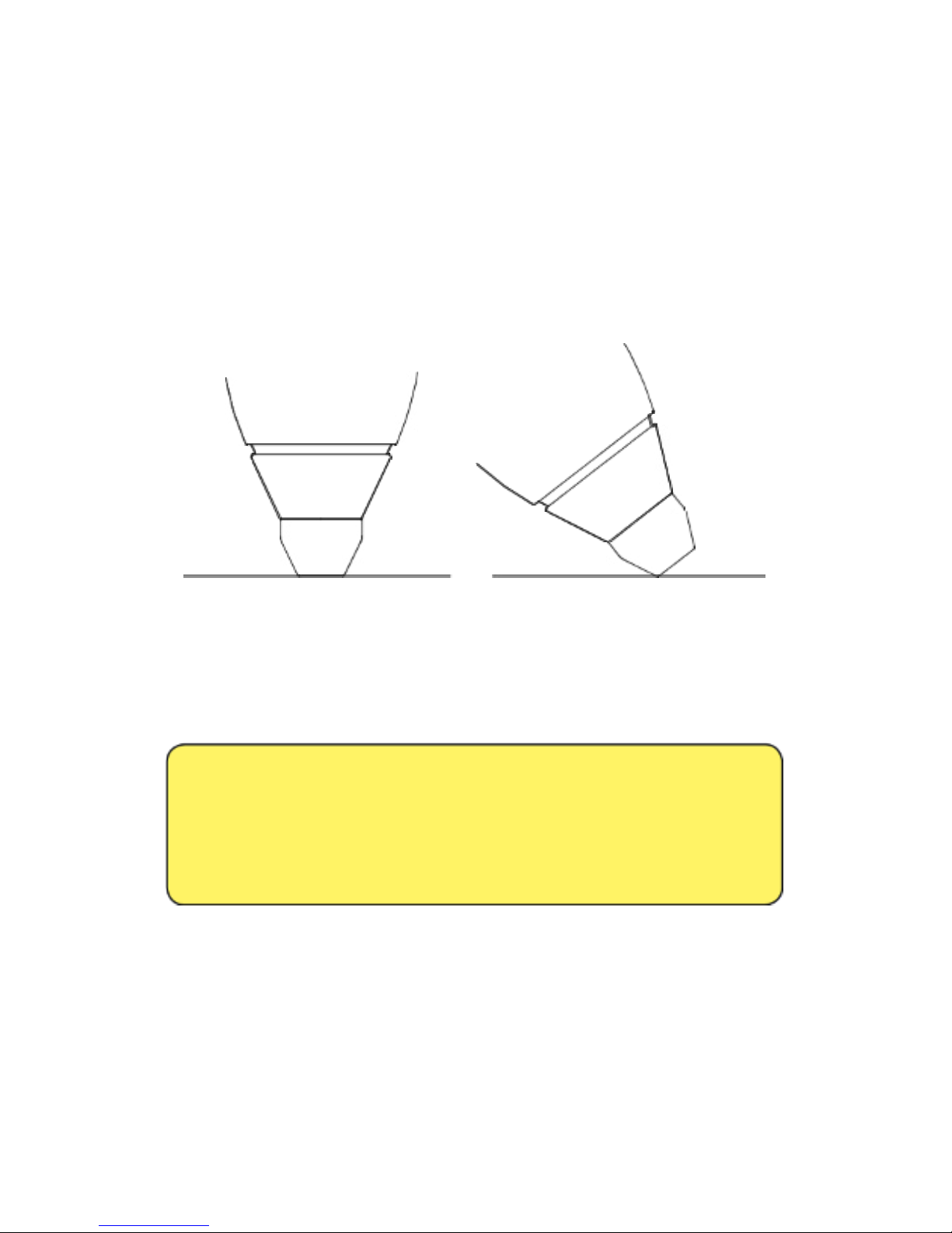
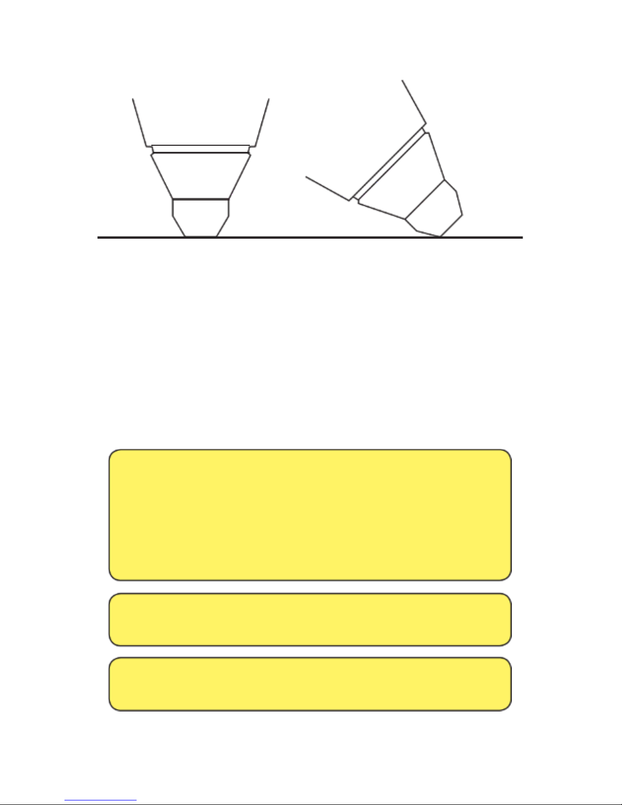
When applying the Treatment Head, ensure that the entire
nosecone tip (also called “body switch”) has complete contact
with the skin and is not applied at an angle. Failure to do so
will allow potentially harmful laser light to irradiate surrounding
areas.
Correct Application Incorrect Application
Figure 1 LD-Series Treatment Head Application
Safety Glasses Use
FAILURE TO FOLLOW THESE INSTRUCTION MAY
RESULT IN SERIOUS INJURY AND/OR BLINDNESS
READ ALL INSTRUCTIONS AND WARNINGS
BEFORE USING THE SYSTEM
• Never use the safety glasses (or eyewear) with other
manufacturer’s equipment.
• Never use other manufacturer’s safety glasses with the BioFlex
system.
Page 10
IX
• Always avoid direct eye exposure to direct or reflected
laser light.
• Ensure that the safety glasses it securely at all times.
• Always check safety glasses before use to assure that
they have not become damaged. Exposure to or
contact with chemical vapors or liquids may also cause
surface cracks or other damage. Do not use if you observe
any type of damage to your eyewear and replace your
eyewear immediately.
• Always keep your safety glasses in the Therapist
carrying case when not in use.
• Never use the safety glasses for any purpose other
than for eye protection while using the system.
Cleaning Instructions
Between patient therapy sessions as indicated
• Wash in mild soap and water.
• Rinse in clean water.
• Air dry or pat dry with a clean, soft tissue.
DO NOT USE AMMONIA, ALKALINE CLEANERS,
ABRASIVE CLEANING COMPOUNDS OR
SOLVENTS
WHEN CLEANING SAFETY GLASSES.
CERTAIN SOLVENTS MAY LOWER THE IMPACT
RESISTANCE OF THE LENSES.
Page 11

X
Safety Kit
The BioFlex Safety Kit consists of the following:
• Laser Safety Guide
• Laser Danger Sign
• Two pairs of safety glasses (one for the practitioner and one
for the patient)
Please read the Laser Safety Guide. Post the danger sign outside
the entrance to the room where the system is located. If
there is
more than one entrance into the room where the system is
located
, please contact Meditech to obtain additional signs
to
post in these areas.
Page 12
XI
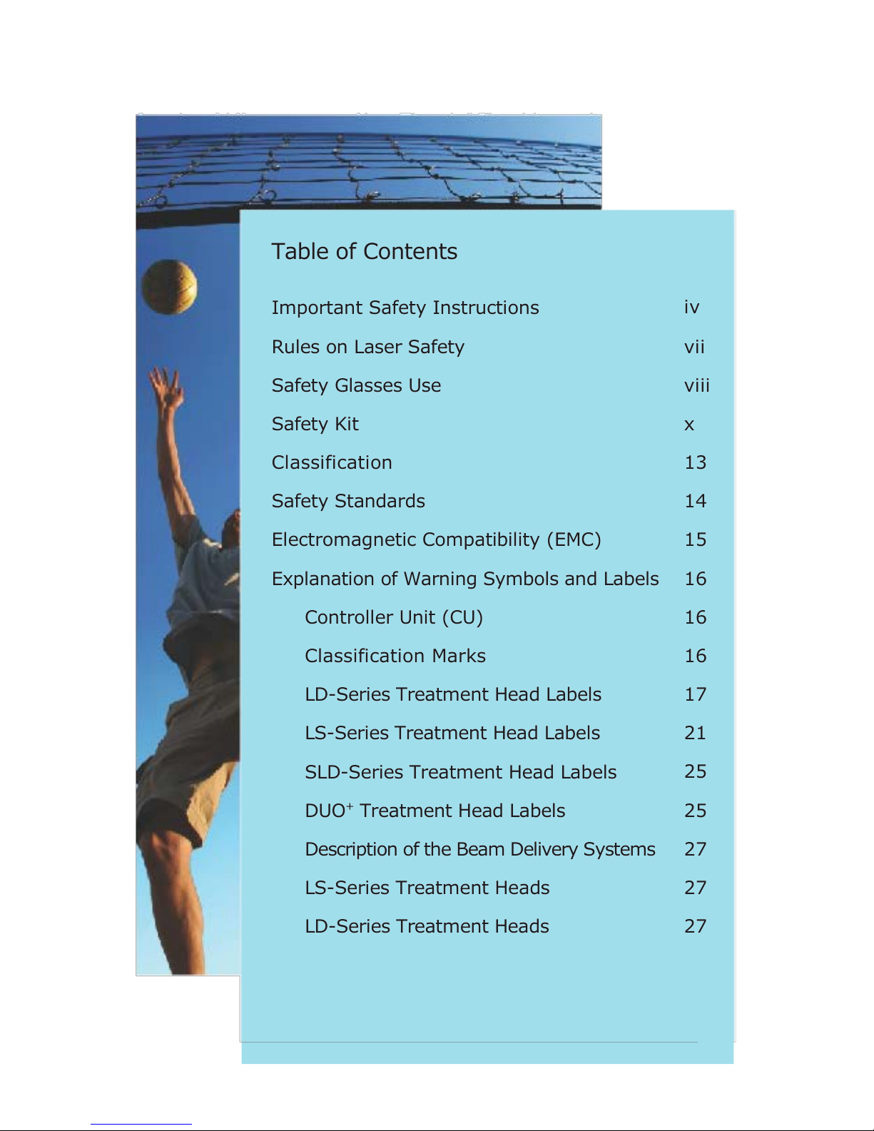
Table of Contents
Important Safety Instructions
Rules on Laser Safety
Safety Glasses Use
Safety Kit
Classification
Safety Standards
Electromagnetic Compatibility (EMC)
Explanation of Warning Symbols and Labels
Controller Unit (CU)
Classification Marks
LD-Series Treatment Head Labels
LS-Series Treatment Head Labels
SLD-Series Treatment Head Labels
DUO
+
Treatment Head Labels
Description of the Beam Delivery Systems
LS-Series Treatment Heads
LD-Series Treatment Heads
iv
vii
viii
x
13
14
15
16
16
16
17
21
25
25
27
27
27
XI
Page 13
XII
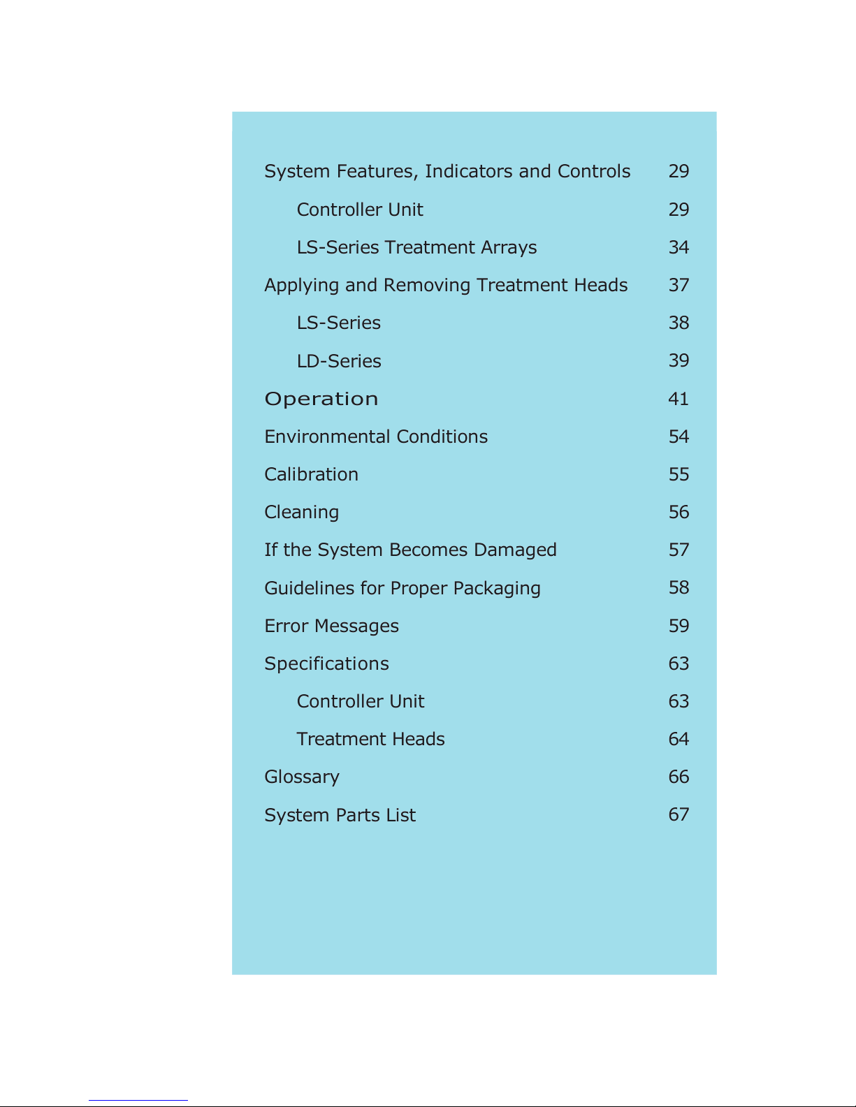
System Features, Indicators and Controls
Controller Unit
LS-Series Treatment Arrays
Applying and Removing Treatment Heads
LS-Series
LD-Series
Operation
Environmental Conditions
Calibration
Cleaning
If the System Becomes Damaged
Guidelines for Proper Packaging
Error Messages
Specifications
Controller Unit
Treatment Heads
Glossary
System Parts List
29
29
34
37
38
39
41
54
55
56
57
58
59
63
63
64
66
67
Page 14

13
Classification
The system is classified as a medical device. Furthermore, it is in
accordance to the Sub-clause 6 of IEC 60601-1 and Clause 6 of
IEC 60601-1:2005:
• CLASS I EQUIPMENT, according to the type of
protection against electric shock;
• TYPE B APPLIED PART, according to the degree of
protection against electric shock;
• NOT CLASSIFIED, according to the degree of
protection against harmful ingress of water;
• CONTINUOUS OPERATION, according to the mode
of operation;
• NONE OF THE PARTS OF THE SYSTEM ARE STERILIZED.
Page 15

14
Safety Standards
This product is classified as medical equipment and has been
tested to comply for the following standards:
Canadian standards
• CAN/CSA C22.2 No. 60601.1, Third ed. - Medical Electrical
Equipment - Part 1: General Requirements for Safety
• CAN/CSA C22.2 No. 601-1.M90 - Medical Electrical Equipment
– Part 1: General Requirements for Safety
• Canadian and United States of America standards
• UL 60601-1, First ed. - Medical Electrical Equipment - Part 1:
General Requirements for Safety
• 21 CFR 1040 - Performance Standards for Light-Emitting
Products
International standards
• IEC/EN 60601-1, Second ed. - Medical Electrical Equipment Part 1: General Requirements for Safety
• ANSI/AAMI ES60601-1:2005 - Medical electrical equipment
- Part 1: General requirements for basic safety and essential
performance
• IEC 60601-1-2 - Medical Electrical Equipment - Part 1:
General Requirements for Safety - 2. Collateral Standard:
Electromagnetic Compatibility - Requirements and Tests
• IEC 60601-2-22:2007 - Medical Electrical Equipment - Part
2: Particular Requirements for the Safety of Diagnostic and
Therapeutic Laser Equipment
• IEC 60825-1 - Safety of Laser Products - Part 1: Equipment
Classification, Requirements and User’s Guide
Page 16

15
Electromagnetic Compatibility (EMC)
This equipment complies with the European rules for EMC
according to the safety standard IEC 60601-1-2. This device
complies with EMC rules under test conditions that include use
of system cables and connectors between system components.
This Equipment requires special precaution regarding the EMC
and must be installed and put into service according to the
information provided in this manual.
The use of accessories and cables other than those specified and
sold by the manufacturer may result in increased emissions or
decreased immunity of the equipment and may cause the system
to be non-compliant with the requirements of IEC 60601-1-2
Replace cables and connectors between components only with
Meditech approved cables and connectors.
This system may cause radio interference or may disrupt the
operation of nearby equipment. It may be necessary to take
mitigation measures, such as reorienting or relocating the
equipment or shielding the location.
Page 17
16
Explanation of Warning Symbols and Labels
This section explains the warning symbols and labels on the
CU and the Treatment Heads. Each Treatment Head has labels
which are located on both sides (underside and topside) of the
Treatment Head.
“Grounding reliability can only be achieved when the
equipment is connected to an equivalent receptacle marked
‘Hospital Grade’.”
Controller Unit (CU)
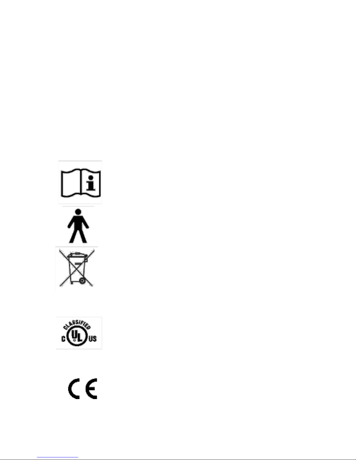
The CONSULT OPERATION MANUAL symbol.
Parts of the system are marked with this warning
symbol when it is necessary for the user to refer
to the instructions in the Operation Manual.
The TYPE B APPLIED PART symbol. This product
is classified as a Type B Applied Part, according to
the degree of protection against electric shock.
This symbol indicates that the waste of electrical
and electronic equipment must not be disposed
as unsorted municipal waste and must be
collected separately.
Classification Marks
The UL mark is a registered trademark of the
Underwriters Laboratories Inc. with respect
to electric shock, ire, mechanical and other
specified hazards only in accordance with CAN/
CSA C22.2 No. 601.1, CAN/CSA C22.2 No.
601.2.22 and UL 60601-1.
The CE mark is a registered trademark of the
European Community
Page 18
17
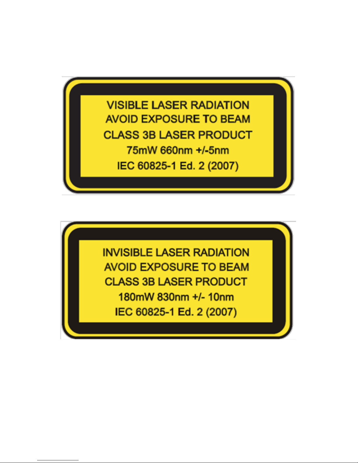
LD- Series Treatment Head Labels
Figure 2 LD-I 75 Treatment Head Explanatory Label
Figure 3 LD-I 200 Treatment Head Explanatory Label
Page 19
18
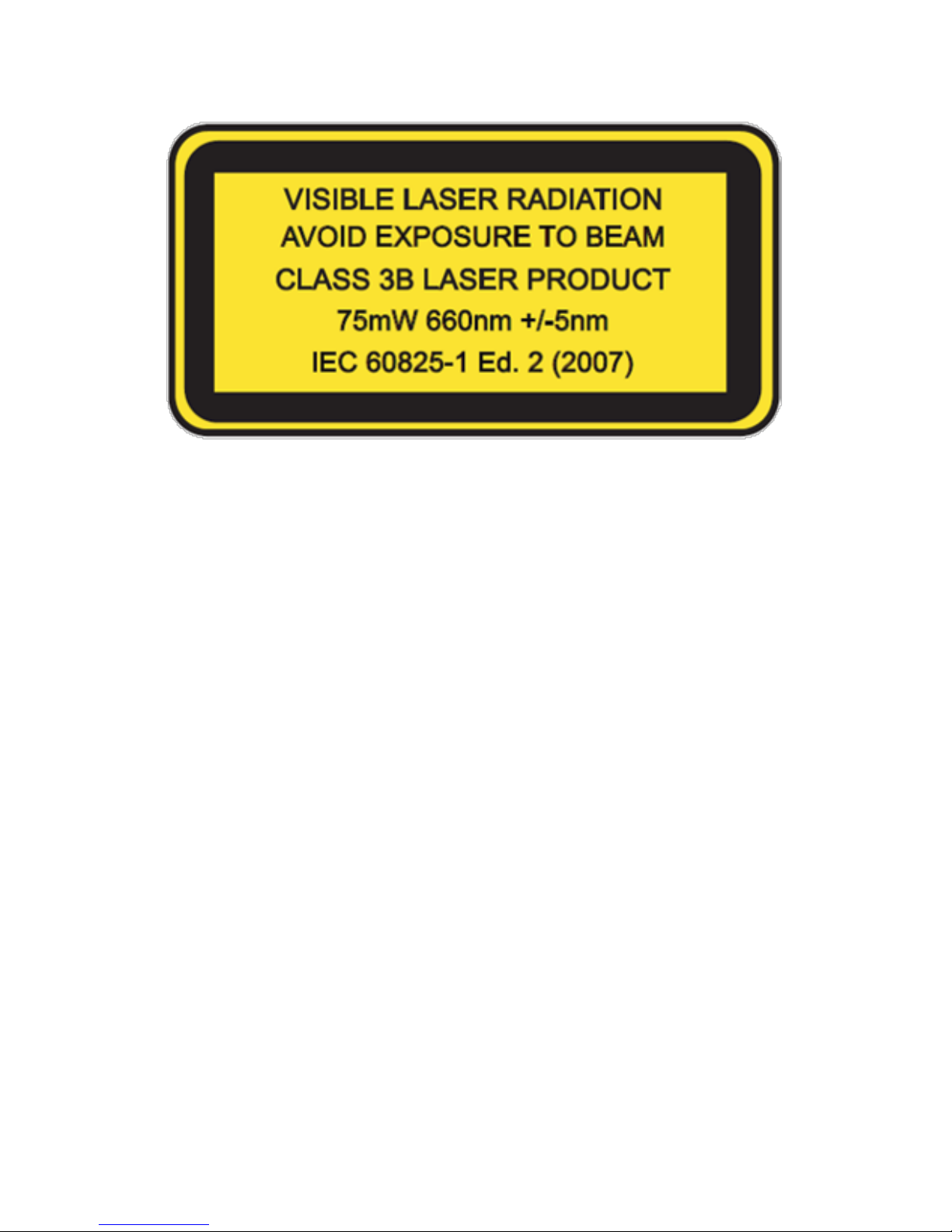
Figure 4 LD-R 100 Treatment Head Explanatory Label
“VISIBLE LASER RADIATION” or “INVISIBLE LASER RADIATION”
Laser (LIGHT AMPLIFICATION BY STIMULATED EMISSION OF
RADIATION) is a device which can be made to produce or amplify
electromagnetic radiation in the wavelength range from 180
nm to 1 mm primarily by the process of controlled stimulated
emission. For the LD-series Treatment Heads, the laser light is
radiated from the top of the Treatment Head nosecone tip (see
section “Description of the Beam Delivery System”).
“AVOID EXPOSURE TO BEAM”
Never look directly into the laser beam or stare at its bright
reflections which are radiated from the aperture of the
Treatment Head.
“CLASS 3B LASER PRODUCT”
This “CLASS 3B LASER PRODUCT” emits laser light at a wavelength
where direct beam viewing is hazardous. Avoid viewing diffuse
reflections.
Page 20
19
For this “CLASS 3B LASER PRODUCT” eye protection is required
and the system has to be operated in an enclosed area where the
entrance should be posted with the provided laser warning sign.
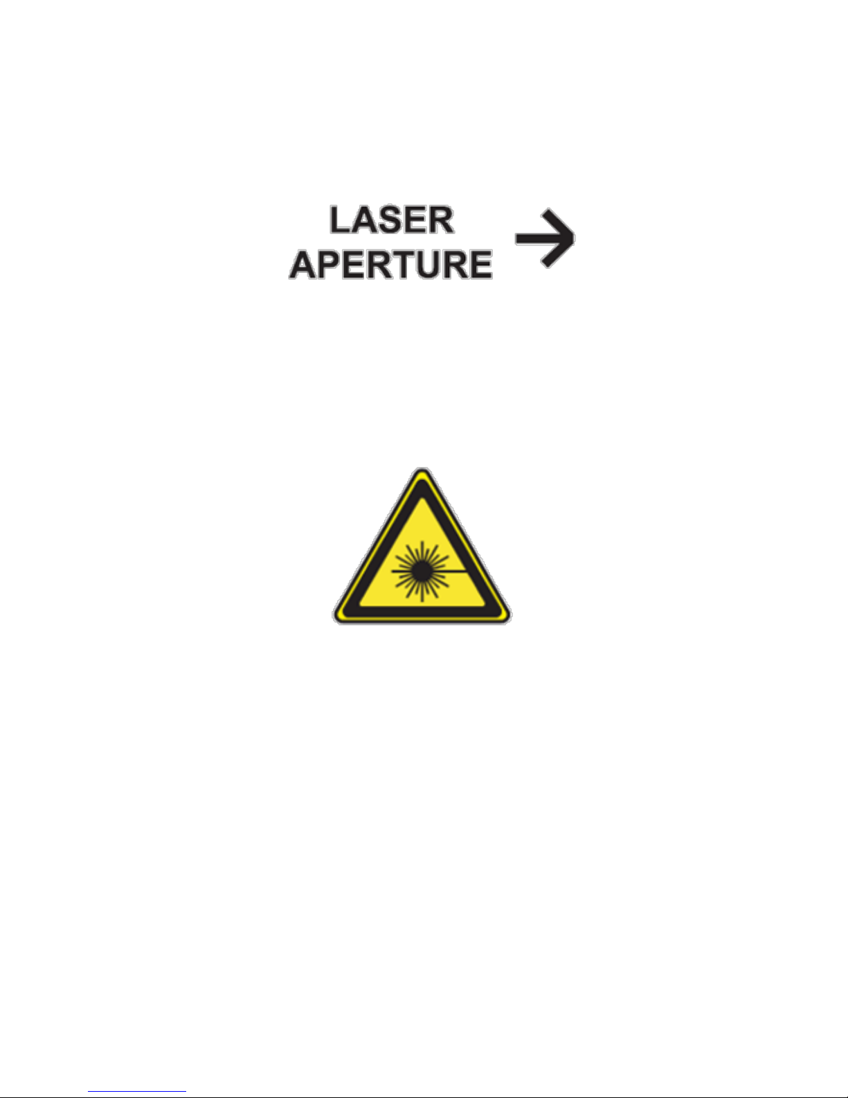
Figure 5 LD-Series Treatment Head Laser Aperture Label
“LASER APERTURE”
This label shows the location of the aperture (LD-series Treatment
Head tip) through which the laser radiation is emitted. Please see
“Description of the Beam Delivery System”.
Figure 6 LD-Series Treatment Head Hazard Symbol
“YELLOW TRIANGLE”
This is a hazard label warning that the system emits hazardous
light. See “CLASS 3B LASER PRODUCT.”
This declaration is required by the U.S. Food and Drug
Administration (FDA) in accordance with the standard 21 CFR
1040 - Performance Standards for Light-Emitting Products.
“This product is in conformity with performance standards for
laser products under 21 CFR 1040, except with respect to those
characteristics authorized by Variance Number 98V0816/7
effective October 7, 1998.”
Page 21
20
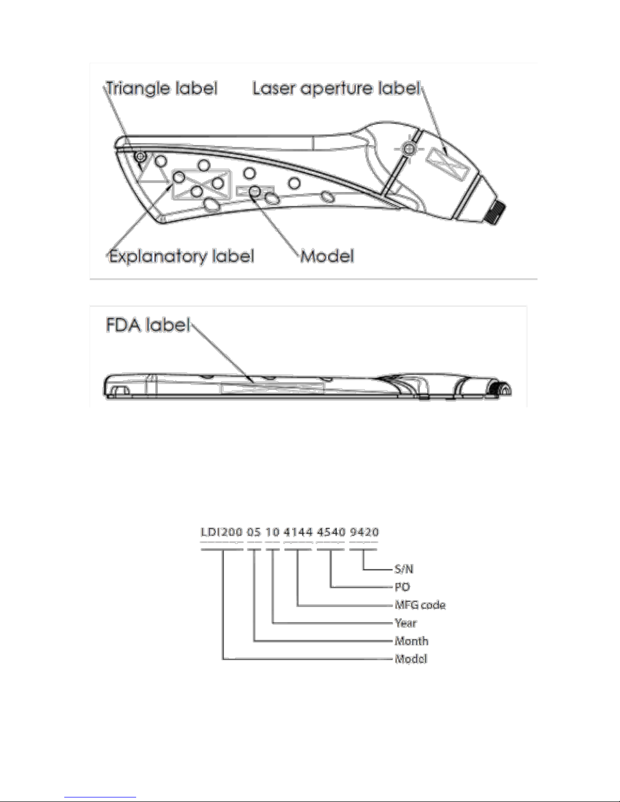
Figure 7 LD-Series Treatment Head Side Label Locations
Figure 8 LD-Series Treatment Head Bottom Label Locations
Date of Manufacture
Refer to the laser treatment head’s serial number label for the
date of manufacture. The format of the serial number is shown
below:
Figure 8a LD-Series Treatment Head Serial Number Format
Page 22
21
LS-Series Treatment Head Labels
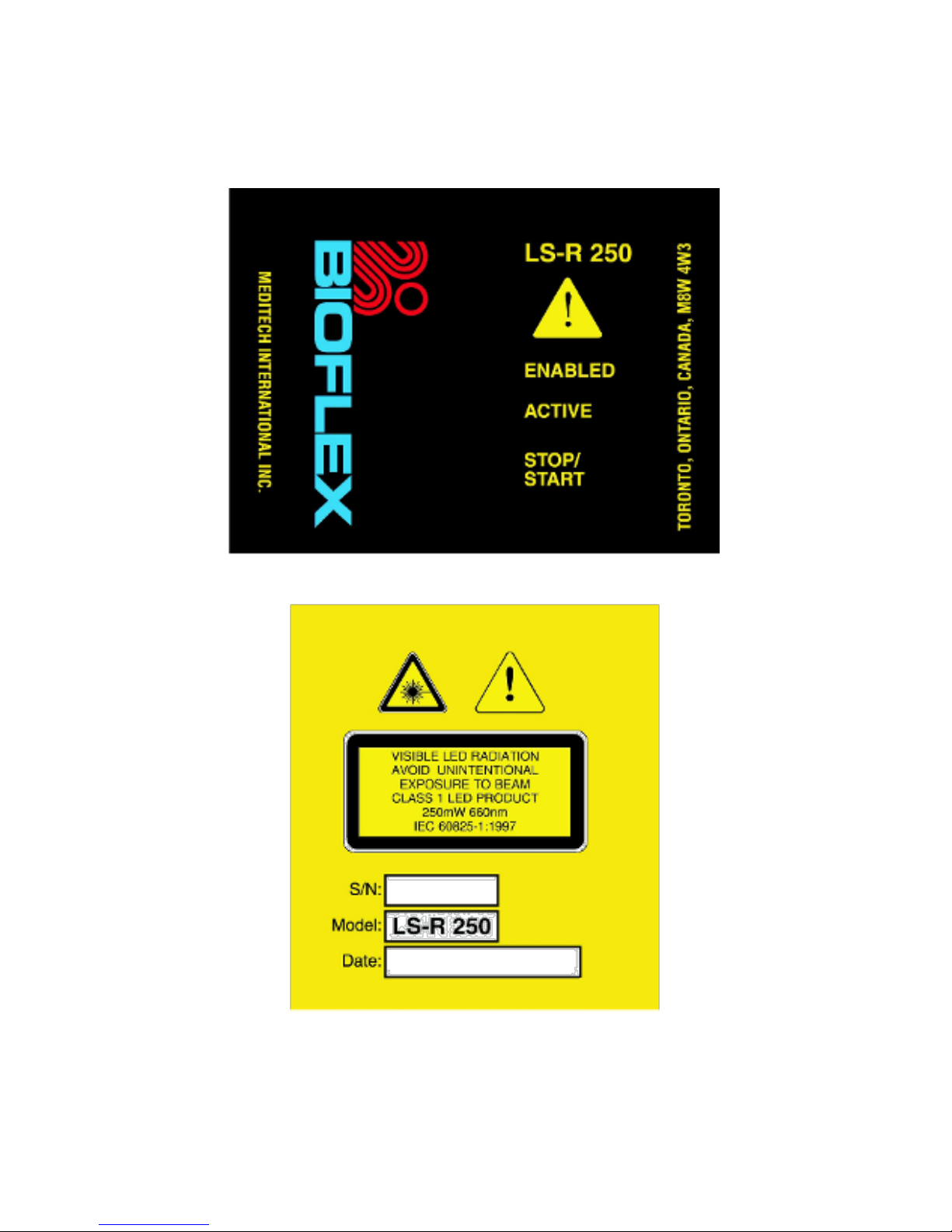
Figure 9 LS-R 250 Treatment Head top label
Figure 10 LS-R 250 Treatment Head bottom label
Page 23
22
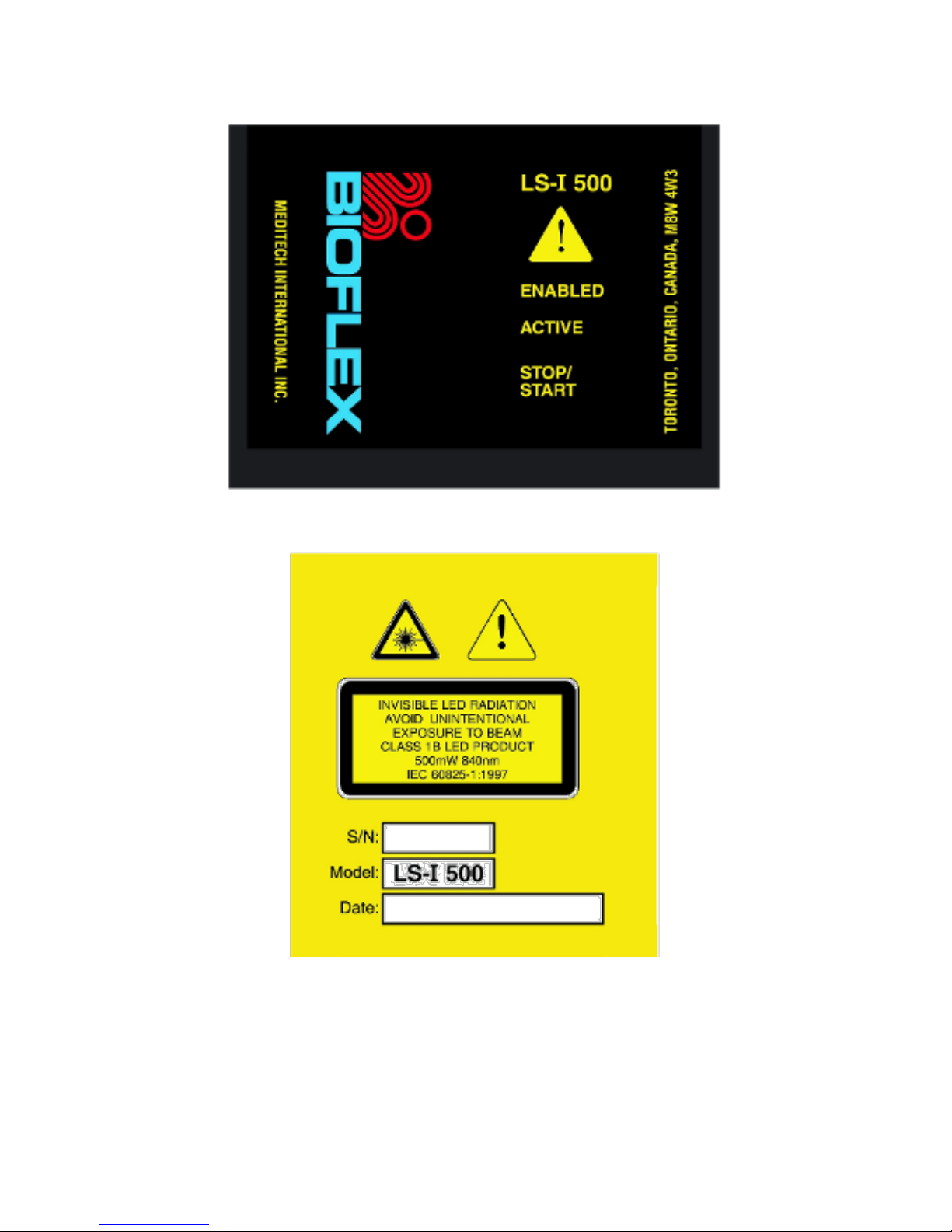
Figure 11 LS-I 500 Treatment Head top label
Figure 12 LS-I 500 Treatment Head bottom label
Page 24
23
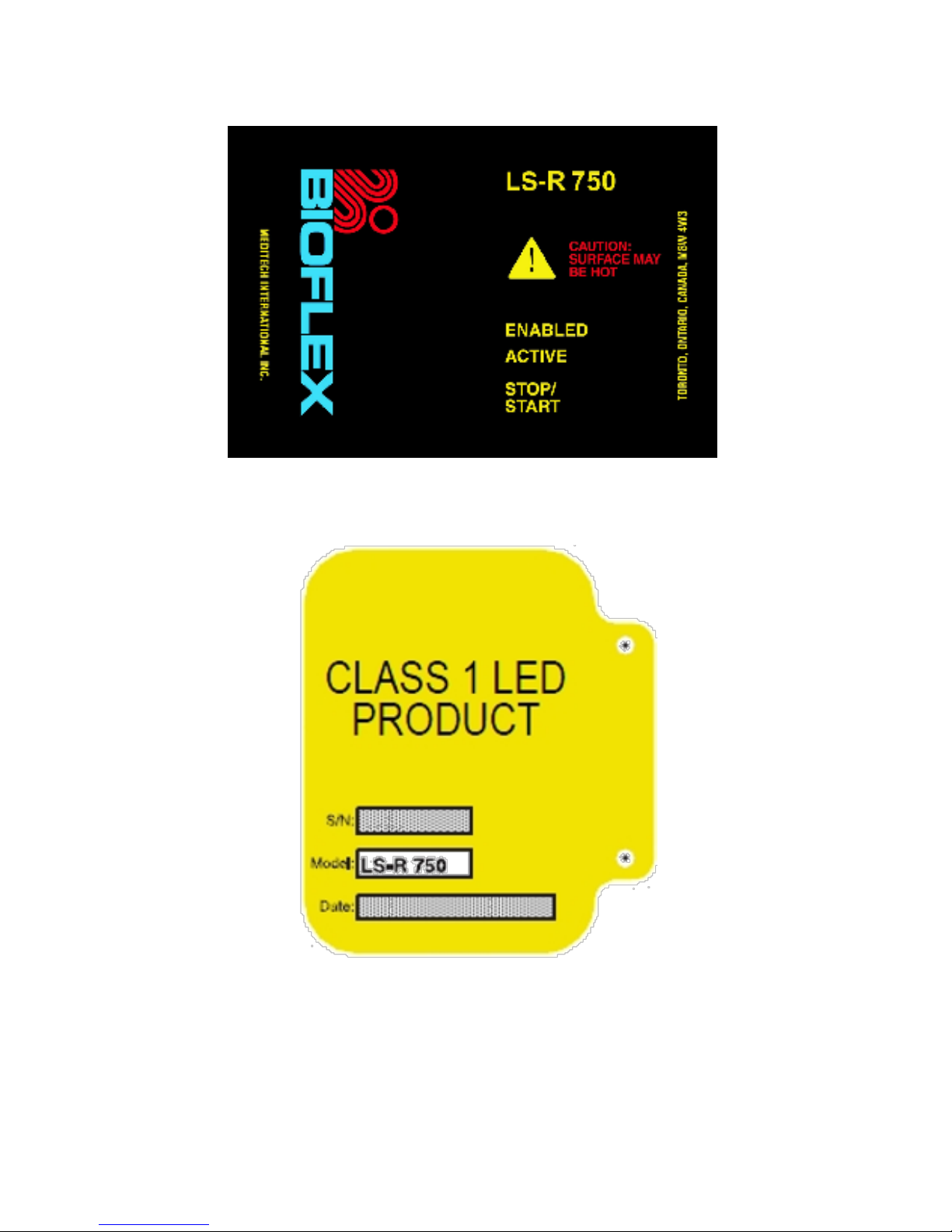
Figure 13 LS-R 750 Treatment Head top label
Figure 14 LS-R 750 Treatment Head bottom label
Page 25
24
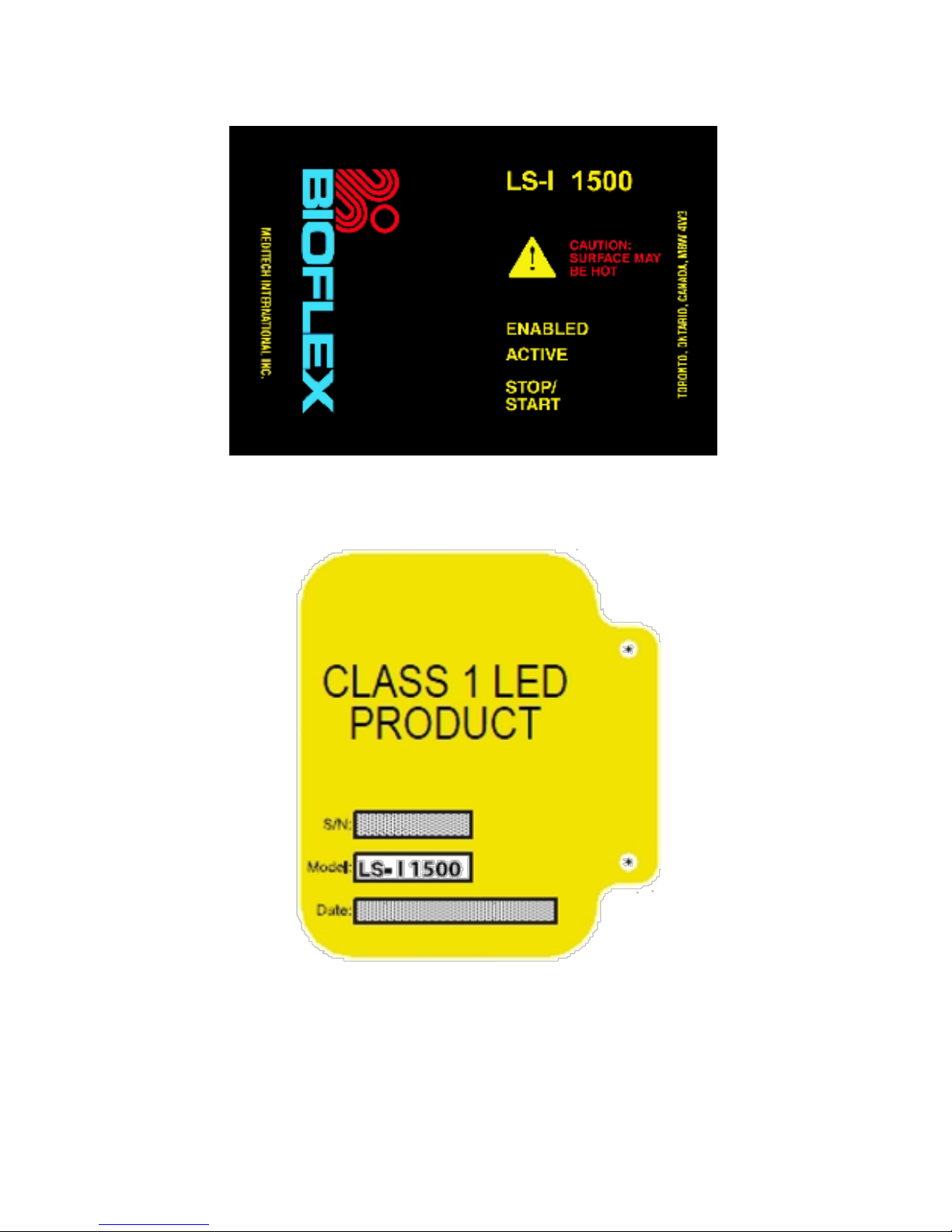
Figure 15 LS-I 1500 Treatment Head top label
Figure 16 LS-I 1500 Treatment Head bottom label
Page 26
25
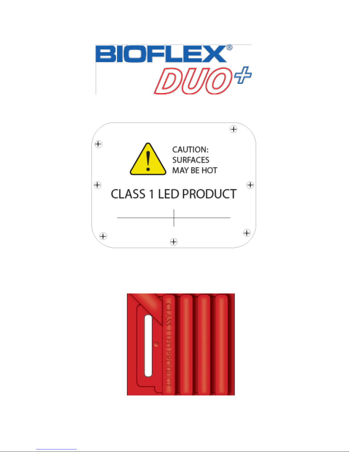
Figure 17a DUO+LS-B 3000 Treatment Head top label
Figure 17b DUO
+
LS-B 3000 Treatment Head bottom label. Refer to
Figure 6a for serial number format and date of manufacture
Figure 18 SLD Treatment Head Label
Page 27

26
“CAUTION: SURFACE MAY BE HOT”
Although Meditech has taken every reasonable precaution to
ensure that the treatment arrays do not become too hot or
uncomfortable for the patient, they still may.
It is the responsibility of the administering practitioner to ensure
the PATIENT’S SAFETY. Prior to starting each treatment, the
patient should be warned that the treatment arrays may become
uncomfortable and that they should notify the administering
practitioner, if they do.
To prevent the treatment array from becoming too warm or
uncomfortable to the patient, it is recommended that the operator
should cool them after 20 minutes of use (e.g. one patient treated
for 20 minutes or four patients treated for 5 minutes each etc.)
by using Meditech’s fan for 2 minutes or 6 minutes at ambient
temperature (without a cooling fan). The above mentioned cooling
procedure applies to protocols with continuous wave mode of
operation at 100% power. With protocols using modulation mode
of operation and/or less power, treatment times can be longer
between cooling periods.
Use caution if very young children or pets are in the patient
environment. It is recommended that the operator should
prevent children from unintentionally touching the treatment
array surfaces because they may not be aware of potential
surface temperatures.
DO NOT cover the treatment arrays during the treatment
because the top surface removes excess heat into the surrounding
environment.
Date of Manufacture
Refer to the “Date:” field on the bottom label of the LS Series
treatment head for the date of manufacture.
Page 28
27
Description of the Beam Delivery Systems
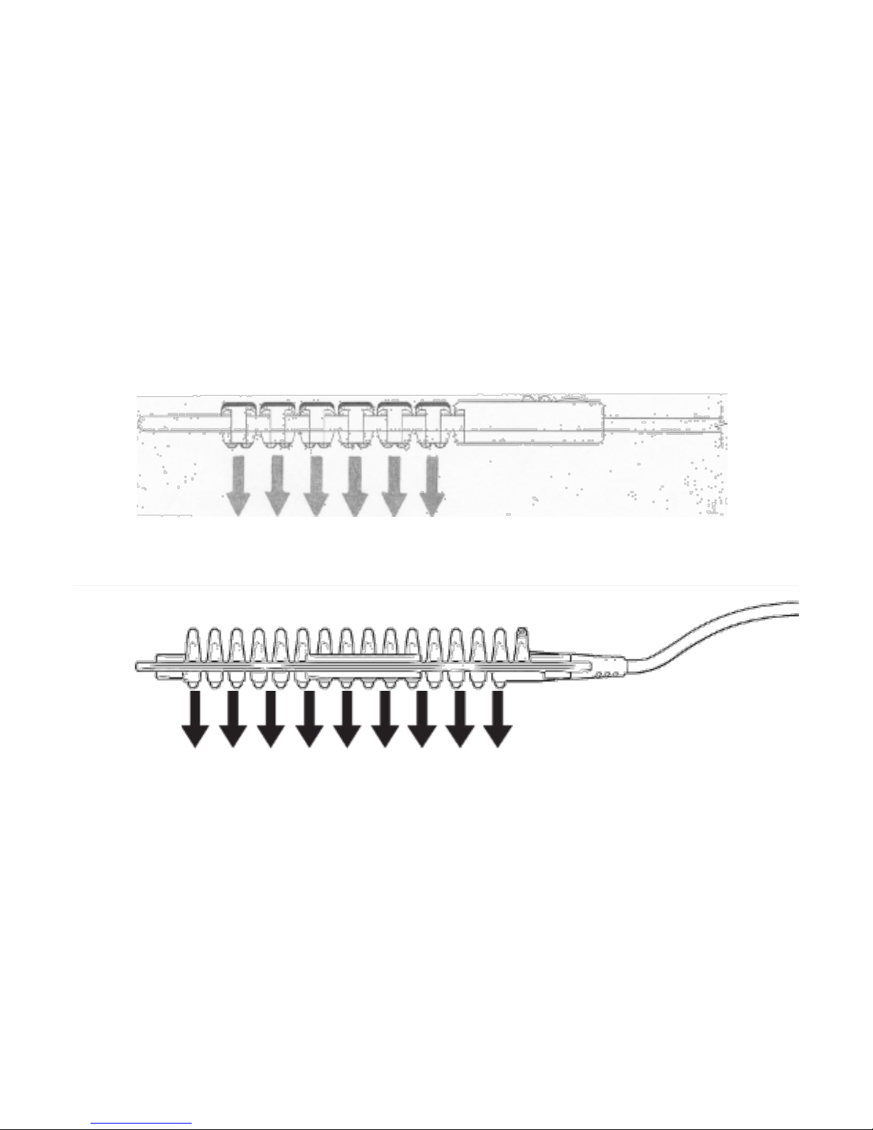
This section explains how the LS or laser light travels from its
origin to the environment for each Treatment Head.
LS-Series Treatment Heads
(Models: LS-R 250, LS-I 500, LS-R 750, LS-I 1500, SLD-R500,
SLD-I1000 and DUO
+
, DUO)
Light radiates from the LS-Series directly into the environment
(shown in figure below).
Figure 19 LS-Series Treatment Head Light Radiation
Figure 19a SLD-Series Treatment Head Light Radiation
Page 29
28
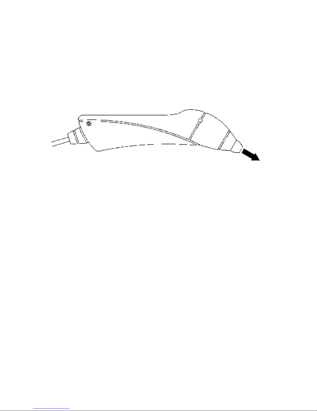
LD-Series Treatment Heads
(Models: LD-R 100, LD-I 75, LD-I 200)
Light radiated from the laser diode located inside the Treatment
Head nosecone passes through an air gap. Then, it goes through
a nosecone window (laser aperture) into the environment as
shown in the figure below.
Figure 20 LD-Series Treatment Head Light Radiation
Page 30
29
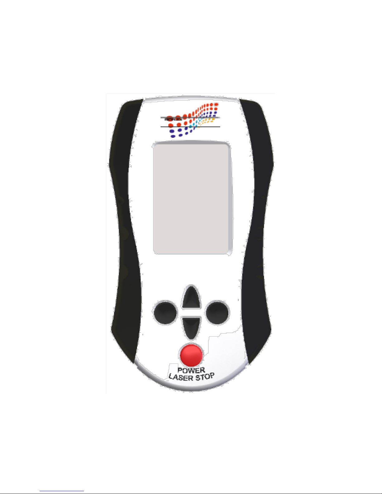
System Features, Indicators and Controls
Controller Unit
THERAPIST
EXIT
Figure 21 Front of CU
SELECT
Page 31

30
To help prevent electric shock, plug the Controller Unit (CU) into
properly grounded power sources. For best grounding, plug into
a
receptacle marked “Hospital Grade.”
Screen
A back-lit liquid crystal display (LCD) provides the user with
information and instructions.
POWER / LASER STOP
• The system is turned on and off by using the POWER / LASER
STOP button on the front of the CU.
• Press once to turn on the system.
• Press POWER / LASER STOP for approximately 1 second to
shut off the system.
• Pressing POWER / LASER STOP during treatment will
immediately stop the treatment and the emission of light.
SELECT and EXIT
Follow the instructions on the bottom of the CU’s screen for when
to use SELECT and EXIT.
UP and DOWN
(Unlabeled Arrow Buttons)
Generally, UP and DOWN allow scrolling through menu items or
selecting values on the CU’s screen. Follow the instructions on
the bottom of the CU’s screen how to use the UP and DOWN
buttons.
Page 32
31
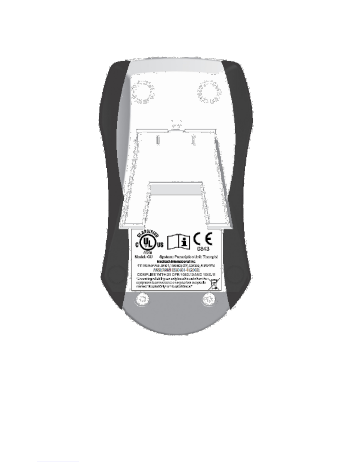
Figure 22 Back of the CU
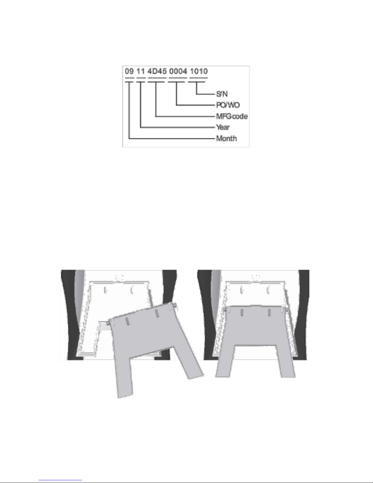
Date of Manufacture
Refer to the CU’s serial number label for the date of manufacture.
The format of the serial number is shown below:
Page 33
32
Figure 22a Serial number format for CU
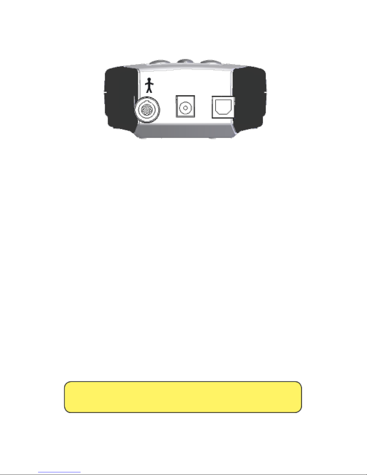
Stand
The stand can be pulled out to allow the CU to rest at an angle
for easy viewing of the screen.
If detached from the CU, the stand can be re-attached as shown
in the following figure.
Figure 23 Replacing the Stand
Page 34
33
POWER
INPUT
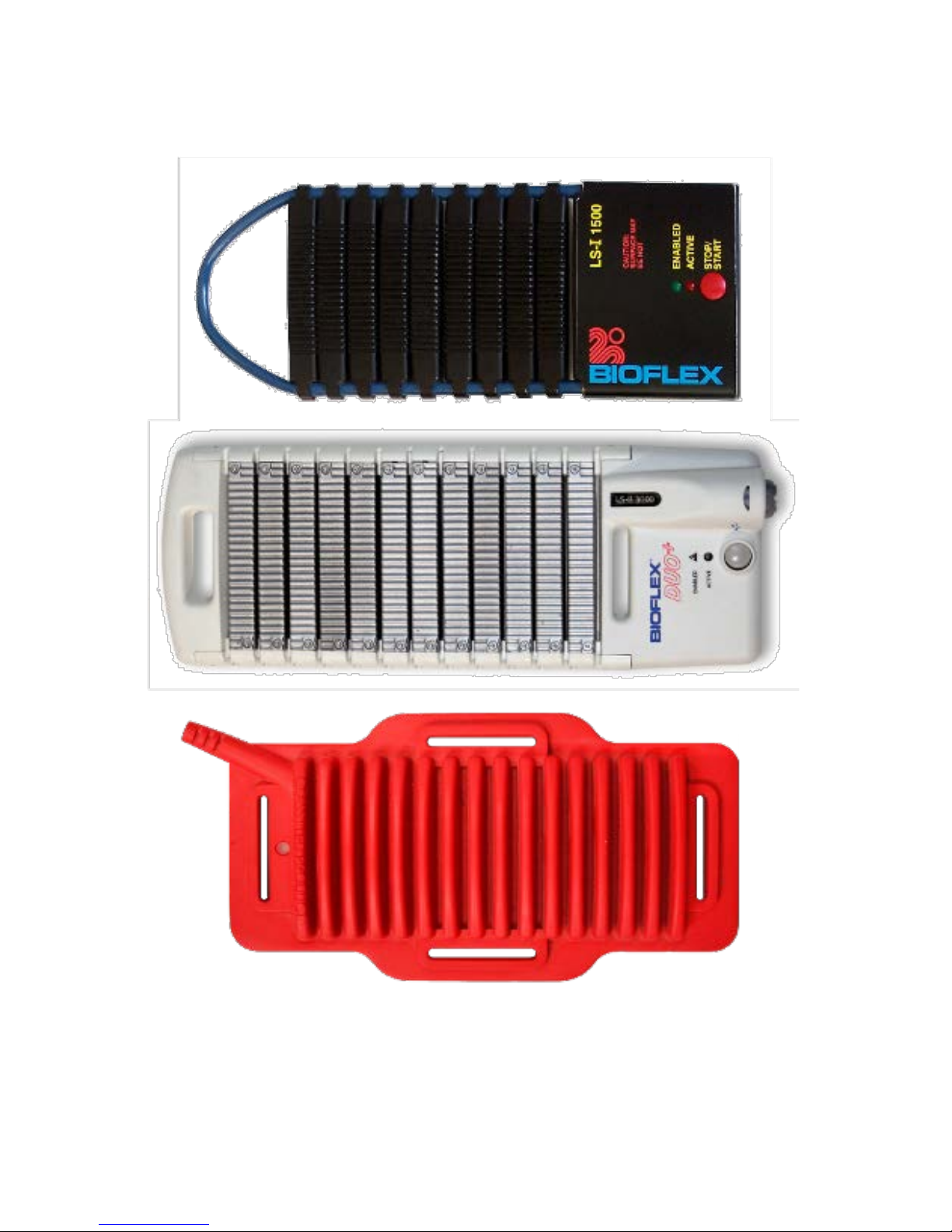
Figure 24 Top of the CU
Treatment Head Port
(Marked with man symbol)
Any Treatment Head may be plugged into port. Plugs and sockets
are polarized; therefore they must be correctly orientated before
they can lock. Align the mark on the plug with the mark on the
socket.
Power Input
Input for the power adapter. Do not use any other adapter except
the one provided by Meditech or your local distributor. Use of
any other power sources will damage this unit.
USB
This port is used when it is required that the system be connected
with a computer.
DO NOT OPERATE THE UNIT WHILE CONNECTED
TO A COMPUTER.
USB
Page 35
34
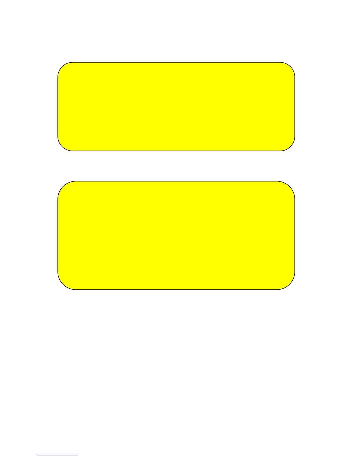
LS-Series & SLD-Series Treatment Arrays
Figure 25 LS Series
Figure 26 DUO Series
Figure 27 SLD Series
Page 36
35
Treatment Array Cooling
For Models LS-R 250, LS-I 500, LS-R 750, LS-I 1500,
SLD-R 500, SLD-I 1000:
Although Meditech has taken every reasonable
precaution to ensure that the Treatment Heads do not
become too hot or uncomfortable for the patient, they
still may. It is the responsibility of the administering
practitioner to ensure the PATIENT’S SAFETY. Prior to
starting each treatment, the patient should be warned
that the Treatment Heads may become uncomfortable
and that they should
notify the administering
practitioner if they do.
To prevent the treatment arrays from becoming
too warm or uncomfortable to the patient, it is
recommended that the operator should cool them
after 20 minutes of use (e.g. one patient treated for
20 minutes or four patients treated for 5 minutes
each etc.) by using Meditech’s fan for 2 minutes or 6
minutes at ambient temperature (without a cooling
fan). The above mentioned cooling procedure
applies to protocols with continuous wave mode of
operation at 100% power. With protocols using
modulation mode of operation and/or less power,
treatment times can be longer between cooling
periods.
Page 37
36
For Models DUO (LS-B 2250) and DUO+ (LS-B
3000):
Safety Features
(For Models LS-R 250, LS-R 750, LS-I 500, LS-I 1500)
The LS-Series Treatment Heads are equipped with an “ambient
light sensor” which will prevent the Head from starting if not
secured to the body. If the Treatment Head is not secure, an
error message (see section “Error Messages”) will be displayed
on the LCD. The operator may then proceed with discretion. The
ambient light sensor is designed to measure the amount of
ambient light present in the room prior to invoking a treatment.
If the Treatment Head is securely attached to the patient, the
amount of ambient light reaching the sensor will be minimal. If
the Treatment Head is not secure, the amount of ambient light
reaching the sensor will be significant. Therefore, the amount of
ambient light may vary in different locations.
To prevent the treatment arrays from becoming
too warm or uncomfortable to the patient, it is
recommended that
the operator should cool
them after 40 minutes o
f use (e.g. one
treatment that delivers 20 minutes of red light
followed by 20 minutes of infrared
light) by
using Meditech’s fan for 2 minutes or 6 minutes
at ambient temperature (without a cooling fan).
The above mentioned cooling procedure applies
to protocols with continuous wave mo
de of
operation at 100% power. With protocols using
modulation mode of operation
and/or less
power, treatment times can be longer between
cooling periods.
If the patient finds that Treatment Head is becoming too
warm or uncomfortable, STOP or PAUSE the
treatment, remove the Treatment Head and allow it to
cool until it is cool to the touch. Use CAUTION, if very
young children or pets are being treated. It is
recommended that the operator watch children for
unintentional contact of the Treatment Head surfaces
because they may not be aware of potential surface
temperatures.
Page 38
37
Applying and Removing Treatment Heads
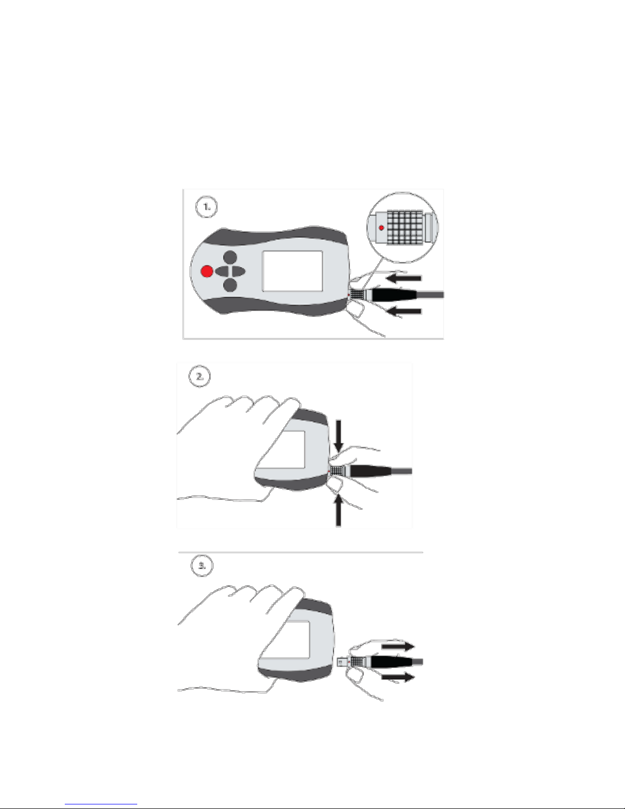
Method of Disconnecting the Treatment Head:
1. Place your thumb and forefinger around the ribbed connector
and exert moderate pressure of the digits against the CU.
2. At the same time, squeeze the connector.
3. Simultaneously, pull away from the CU to extract the cable.
Figure 28 Disconnecting Treatment Array
Page 39
38
LS-Series and SLD-Series
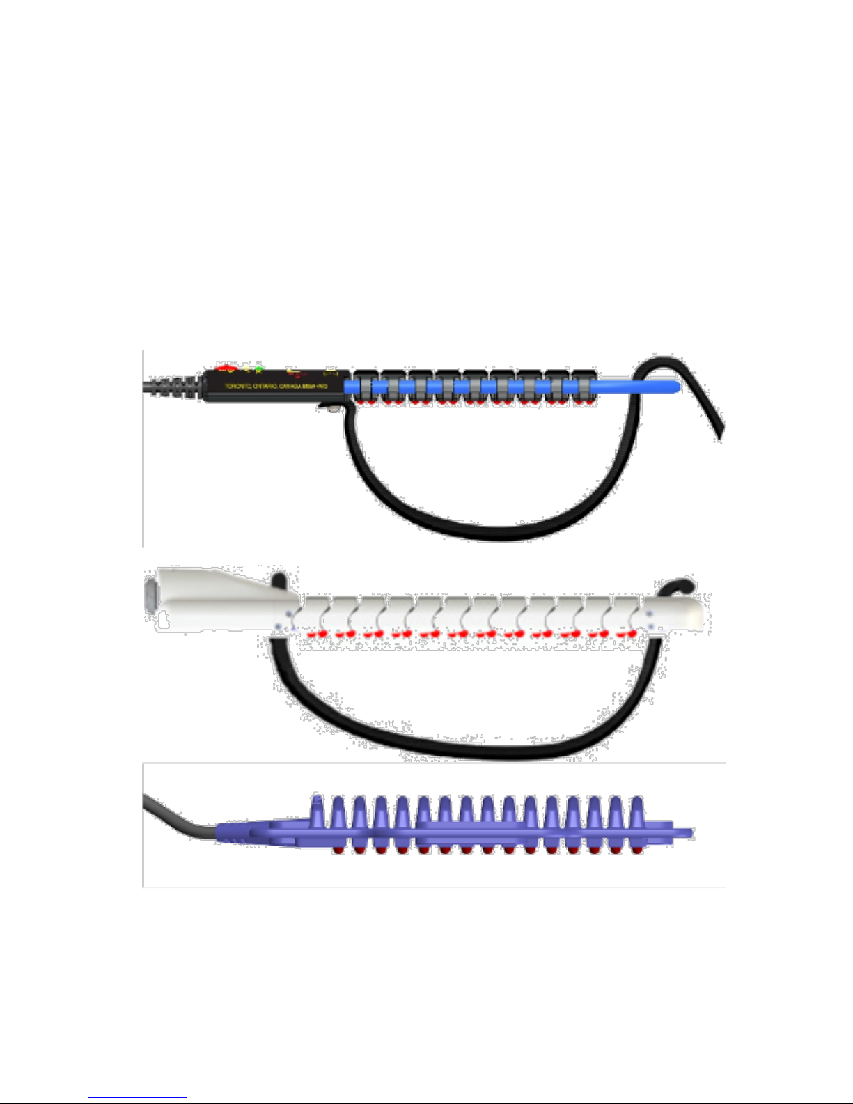
The LS-Series Treatment Arrays may be secured directly to the
body using the attached straps.
When applying, place the Treatment Array over the area to be
treated and wrap the straps around the body part. Place the
Velcro from one strap over the Velcro portion of the other strap.
To remove, unlock the Velcro and remove the Treatment Array.
Figure 29 Applying the Treatment Arrays
Page 40
39
Warnings for Using the Treatment Arrays:
• Do not twist
• Do not hyperextend
• Do not drop
• Do not tamper with diodes
Note: The Treatment Arrays must be secured to
allow air circulation around the top of the head. Do
not cover the heads while running treatments,
however you can use the Meditech approved
weight set.
LD-Series
Body Switch and Indicator
The LD-Series Treatment Heads are activated when the nosecone
tip contacts the skin. After selecting a treatment or continuing
to the next phase, wait until the indicators on the Treatment
Head turn green before applying the Head. Once the indicators
are green, apply the Treatment Head tip to the treatment area
and the treatment will begin (the indicators will turn amber).
Removal from the skin will cease treatment and the indicators
will return to green.
NOTE: When applying the Treatment Head, it is
important to ensure that the flat end makes full
contact with the skin.
Failure to do so might
expose bystanders to potentially dangerous laser
radiation. Refer to the pictures below for the
correct and incorrect application of the Treatment
Head.
A Treatment sleeve MUST always be used for
broken or compromised skin.
Page 41
40
Correct Application Incorrect Application
Radiation ceases immediately when:
• Contact with the skin ceases.
• Pressing the “UP”, DOWN” or “SELECT” buttons.
• Pressing “LASER STOP” button.
The system is a stand-alone unit.
NOTE: After selecting a treatment or continuing
to the next phase, do NOT touch the tip of the
Treatment Head until the indicators on the head
turn green; otherwise the Treatment Head will not
work. If you do touch the tip before the indicators
turn green, you will have to stop and restart the
treatment to re-activate the Treatment Head.
DO NOT UNPLUG THE TREATMENT HEAD WHILE IT
IS ACTIVE.
DO NOT OPERATE THE UNIT WHILE CONNECTED TO
A COMPUTER.
Page 42
41
Operation
The following pages show screen shots and describe how to use
the various functions of the BioFlex Therapist System:
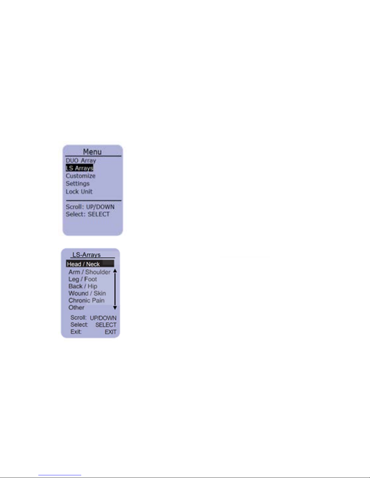
Main Screen Menu
From the MAIN MENU you can select to run a treatment, customize a
treatment, adjust the settings of the unit and also lock the unit
from unauthorized use.
This is the main menu when
the system is operating.
Select “Run Treatment” from the
main menu.
Use the
UP/DOWN buttons to scroll to
the Anatomy you are treating
and press
SELECT
Page 43
42
Scroll:
Select:
Exit:
Scroll:
Select:
Exit:
Scroll:
Select:
Exit:
UP/DOWN
SELECT
EXIT
UP/DOWN
SELECT
EXIT
1 of 9
LS-R750
6min
CW
N/A
N/A
100%
UP/DOWN
SELECT
EXIT
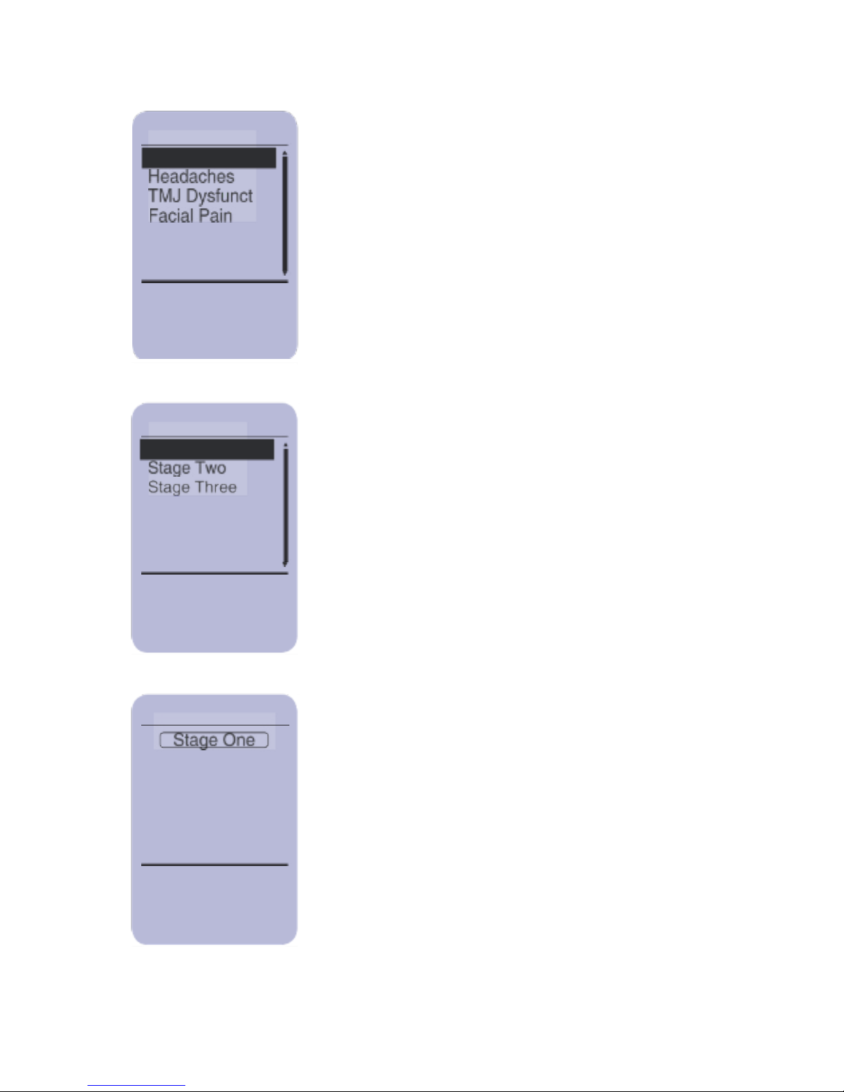
Use the UP/DOWN buttons to scroll to the
Pathology you want to treat and press
SELECT
Use the UP/DOWN buttons to scroll to
the Intensity you want to use and press
SELECT.
Press the
UP/DOWN buttons to view the
Treatment Information. Press the
UP/DOWN buttons to scroll through
the Stages of the Treatment.
Pathology
C-Spine
Intensity
Stage One
Run Treatment
Page 44
43
LS Arrays
View:
Start:
Exit:
LS Arrays
LS Arrays
DBL CLICK
EXIT
LASER STOP
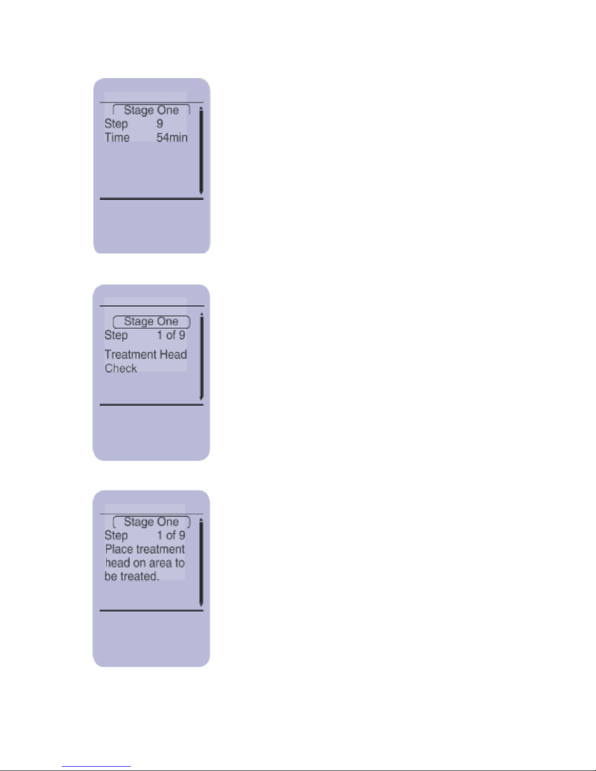
To start the treatment press SELECT
During this time the Controller performs a
treatment Head Check to test functionality of
the System.
The screen now asks you to place the
treatment head on the area to be treated.
Apply the Treatment Heads as described
in “Applying and Removing the Treatment
Heads” section. Put the safety glasses
provided with your system on and press
SELECT to start the treatment.
UP/DOWN
SELECT
EXIT
Run:
Cancel:
Stop
Page 45
44
LS Arrays
Pause:
Pause:
Pause:
LS Arrays
PAUSED
DBL CLICK
EXIT
LASER STOP
LS Arrays
SELECT
EXIT
LASER STOP
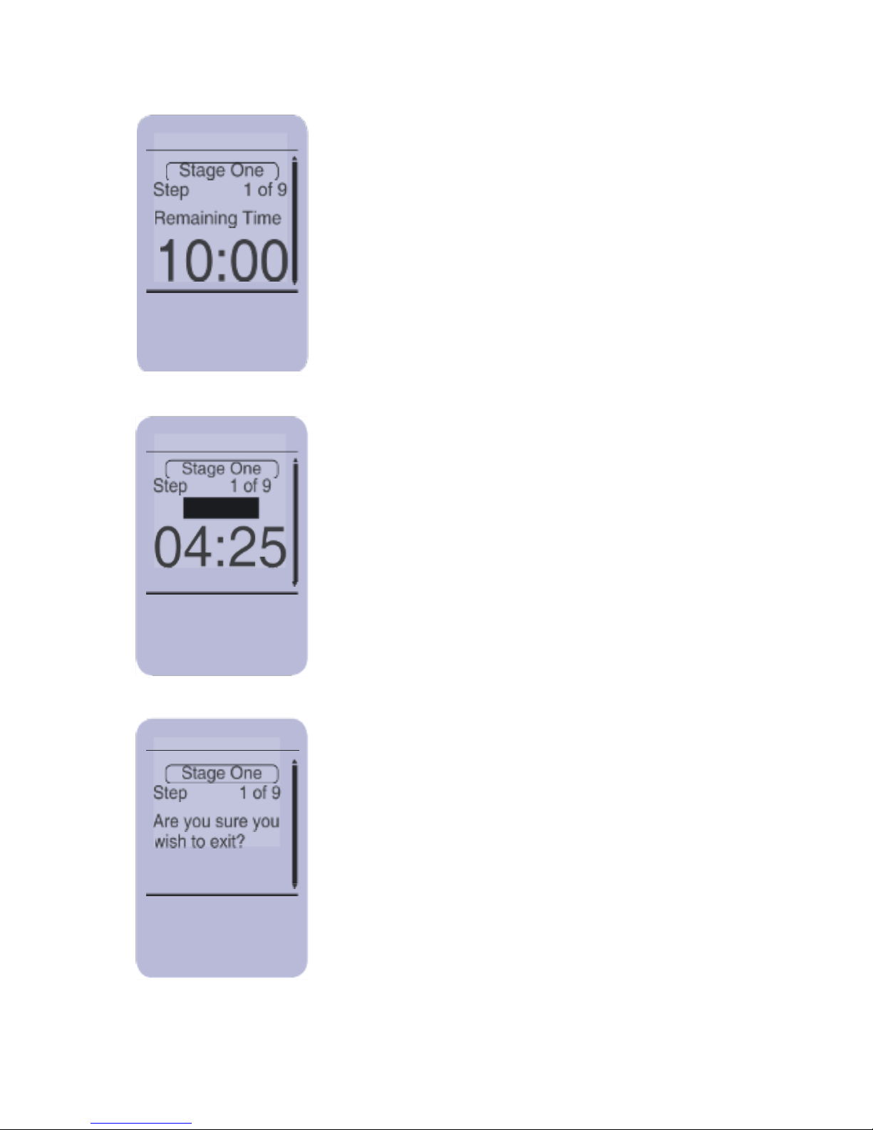
This screen informs you of the current phase
and time remaining for current phase of the
protocol. The
LASER STOP button can be
pressed at any time during the treatment to
immediately stop the emission of radiation
and cease treatment.
Pressing either of the
UP/DOWN, EXIT or
SELECT buttons will pause the treatment.
To continue the treatment press SELECT. To
cancel treatment, press
EXIT and follow the
on-screen menu. To stop the treatment
press
LASER STOP.
The exit screen.
UP/DOWN
SELECT
EXIT
Run:
Cancel:
Stop:
No:
Exit:
Stop:
Page 46
45
Step 1 of 3
TH
Time
WaveForm
Frequency
DutyCycle
Power
Run Treatment
Scroll:
Select:
Exit:
Step 1 of 3
TH50
Time
WaveForm
Frequency
DutyCycle
Power
Run Treatment
Scroll:
Select:
Exit:
Pressing SELECT while the step number is
highlighted allows scrolling through the
phases.
To set the Treatment Head (TH), Time,
Waveform, Frequency, Duty Cycle
and Power, highlight the parameter and
press SELECT. The highlighted area will
change (see below).
Customize a Treatment
This section instructs you on how to customize a protocol using
the Therapist CU.
UP/DOWN
SELECT
EXIT
UP/DOWN
SELECT
EXIT
6 min
Squa
5000
90%
100%
TH LS-R750
LS-R750
6 min
Squa
5000
90%
100%
Page 47
46
Step 1 of 3
LS-R750
Time
WaveForm
Frequency
DutyCycle
Power
Run Treatment
scroll:
select:
exit:
Step 1of 3
TH
Time
WaveForm
Frequency
DutyCycle
Power
Run Treatment
Scroll:
Select:
Exit:
Customize
Step One
Scroll:
Select:
Exit:
To set the specific parameter use the UP/
DOWN buttons to scroll through the options.
When you have found the option you want
to use, press SELECT to initiate change.
To Run the protocol just created plug in
the appropriate head, scroll to Run
Treatment from any phase and press
SELECT.
Treatment will always start from step 1.
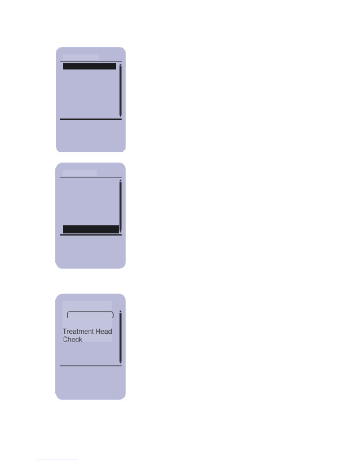
During this time the Controller performs a
Treatment Head Check to test functionality
of the System.
Run Treatment
UP/DOWN
SELECT
EXIT
LS-R750
6min
Squa
5000
90%
100%
UP/DOWN
SELECT
EXIT
UP/DOWN
SELECT
EXIT
6min
Squa
5000
90%
100%
TH
Page 48
47
Customize
Step One
Scroll:
Select:
Exit:
Customize
Step One
Scroll:
Select:
Exit:
Customize
Step One
PAUSED
Scroll:
Select:
Exit:
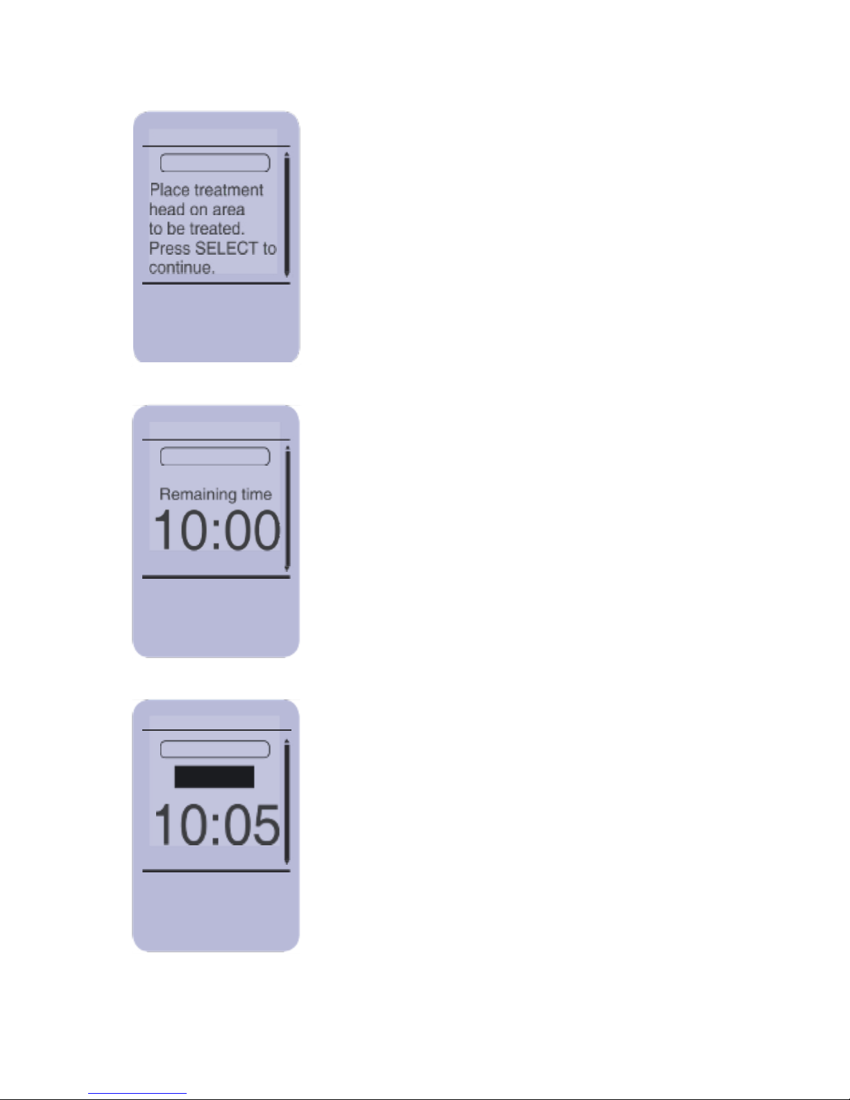
The screen now asks you to place the
Treatment Head on the area to be treated.
Apply the Treatment Heads as described
in “Applying and Removing the Treatment
Heads” section. Place the safety glasses
provided with your system on and press
SELECT to initiate treatment.
This screen informs you of the current phase
and time remaining for current phase of the
protocol. The LASER STOP button can be
pressed at any time during the treatment to
immediately stop the emission of radiation
and cease treatment.
Pressing either of the UP/DOWN, EXIT or
SELECT buttons will pause the treatment.
To continue the treatment press SELECT. To
cancel treatment, press EXIT and follow the
on-screen menu. To stop the treatment
press LASER STOP.
UP/DOWN
SELECT
EXIT
UP/DOWN
SELECT
EXIT
UP/DOWN
SELECT
EXIT
Page 49
48
Customize
Step One
SELECT
EXIT
LASER STOP
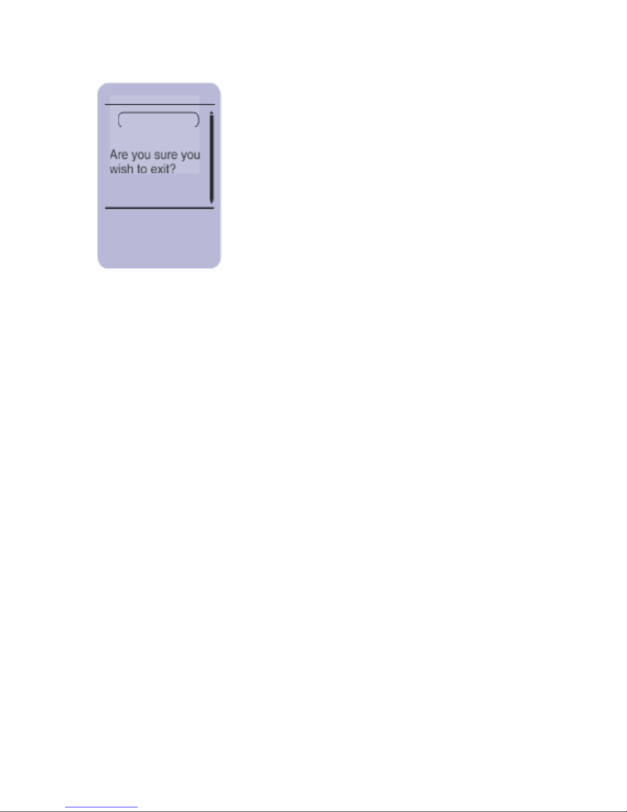
The exit screen.
No:
Exit:
Stop:
Page 50
49
Settings
This section describes how to change the various settings.
The settings will be discussed in more detail in the following
illustrations.
Settings
Default Array
Scroll:
Select:
Exit:
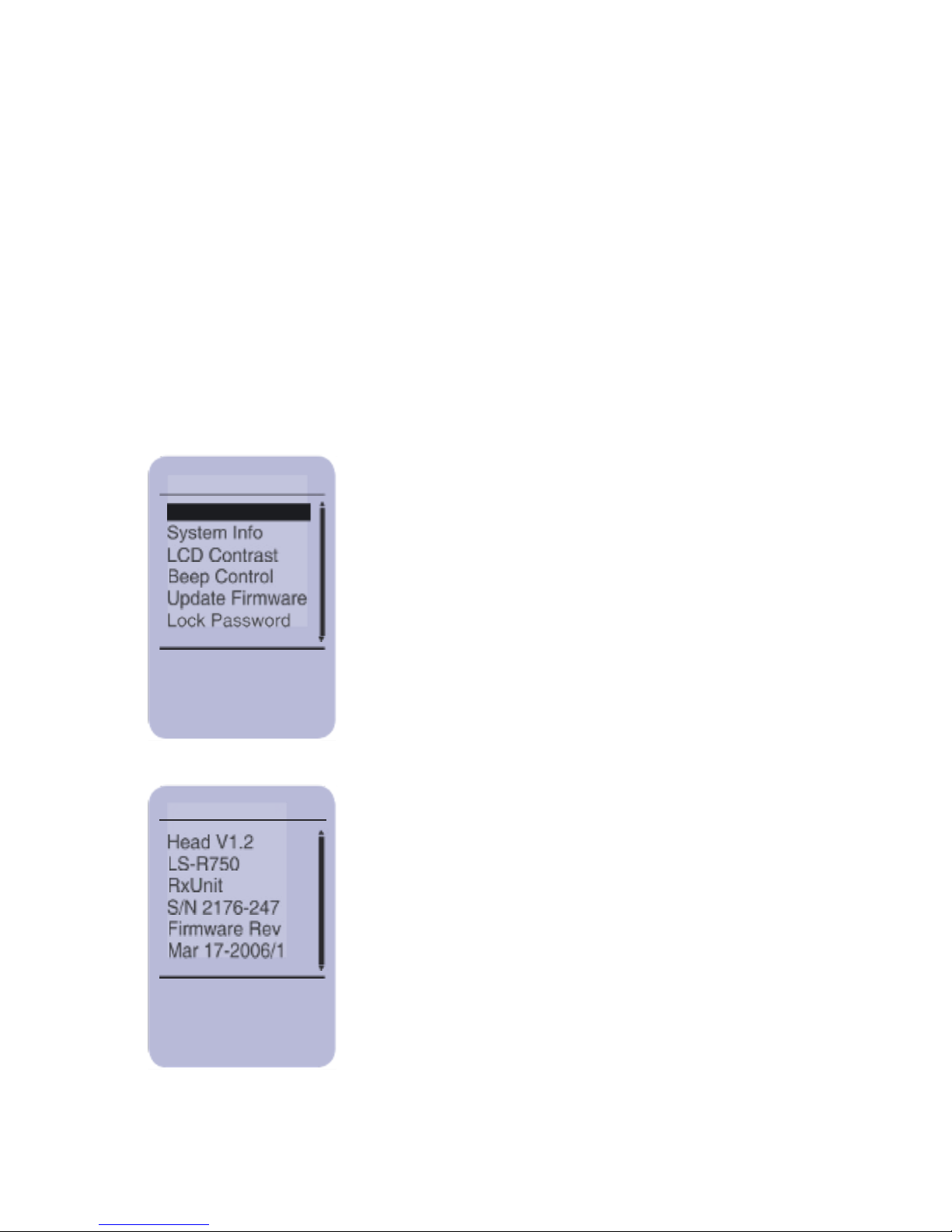
System Info
This screen provides the Treatment Head
serial number, firmware version and the
Controller serial number and firmware
version. Press EXIT to go back to the
Settings menu.
Exit:
UP/DOWN
SELECT
EXIT
EXIT
Settings Main Screen
To select an item from the menu, scroll
through the options until the item is
highlighted and press SELECT.
System Info
Page 51
50
Change:
Select:
Exit:
Adjust:
Select:
Exit:
Update:
Exit:
UP/DOWN
SELECT
EXIT
UP/DOWN
SELECT
EXIT
SELECT
EXIT
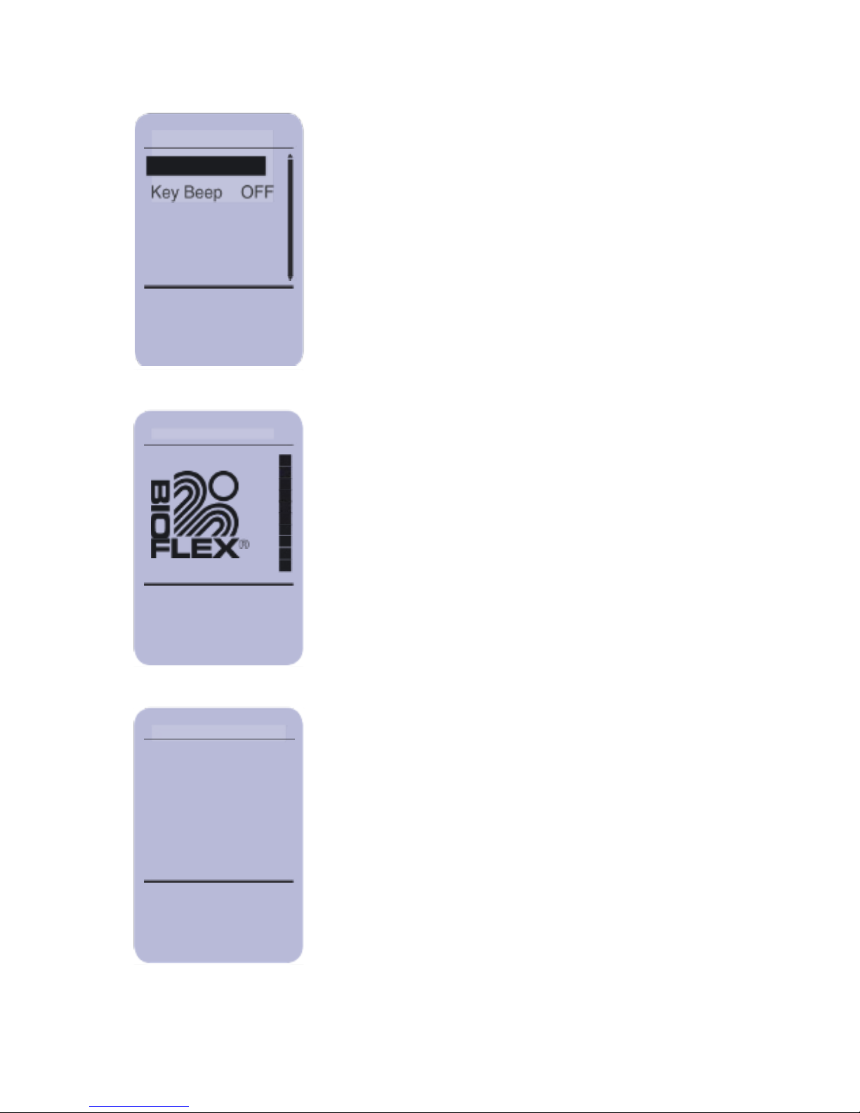
Beep Control
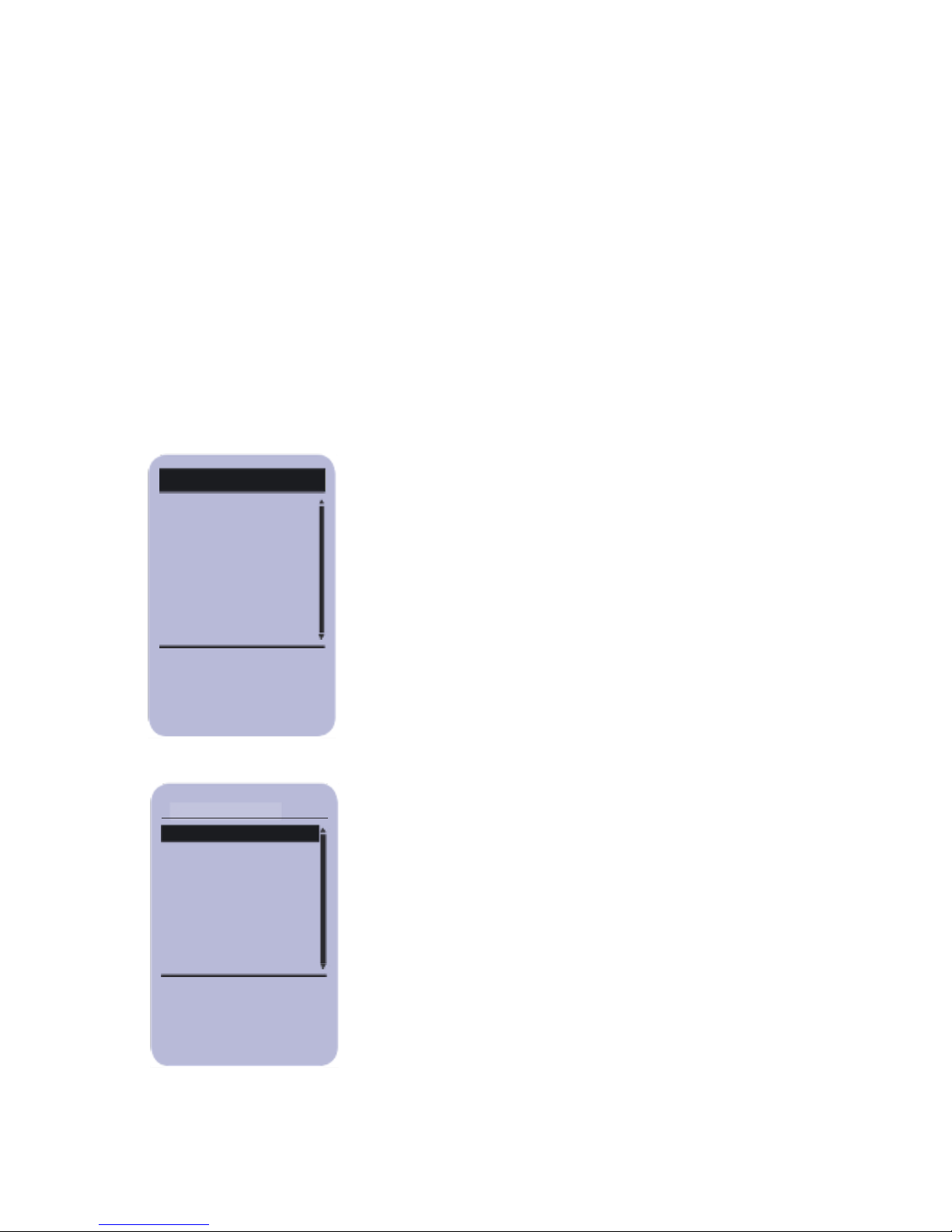
The Key Beep can be turned on or off. Key
Beep is the audible beep heard when a
button is pressed. This does not turn off the
beeps heard during treatment. Use the
UP/DOWN buttons to select either Key Beep
ON or Key Beep OFF and press
SELECT.
LCD Contrast
To adjust the contrast of the screen use the
UP/DOWN buttons to adjust the levels of
contrast to the desired level. Press
SELECT to accept or press EXIT to keep
current settings.
Update Firmware
This menu option is used to update the
Controller or Treatment Head firmware if a
new version has been released.
Beep Control
Key Beep ON
LCD Contrast
Update Firmware
Page 52
51
Scroll:
Select:
Exit:
UP/DOWN
SELECT
EXIT
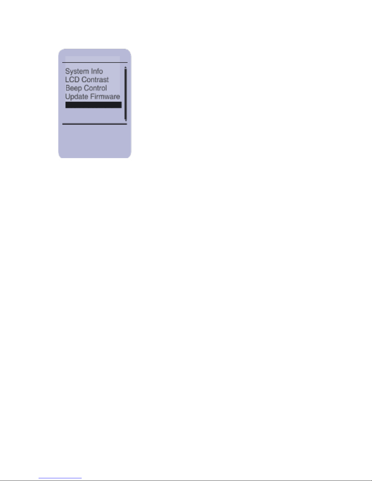
Lock Password
This option is used to change the Lock
Password. If you change the password write
it down and place it in a safe and secure
location.
Settings
Lock Password
Page 53
52
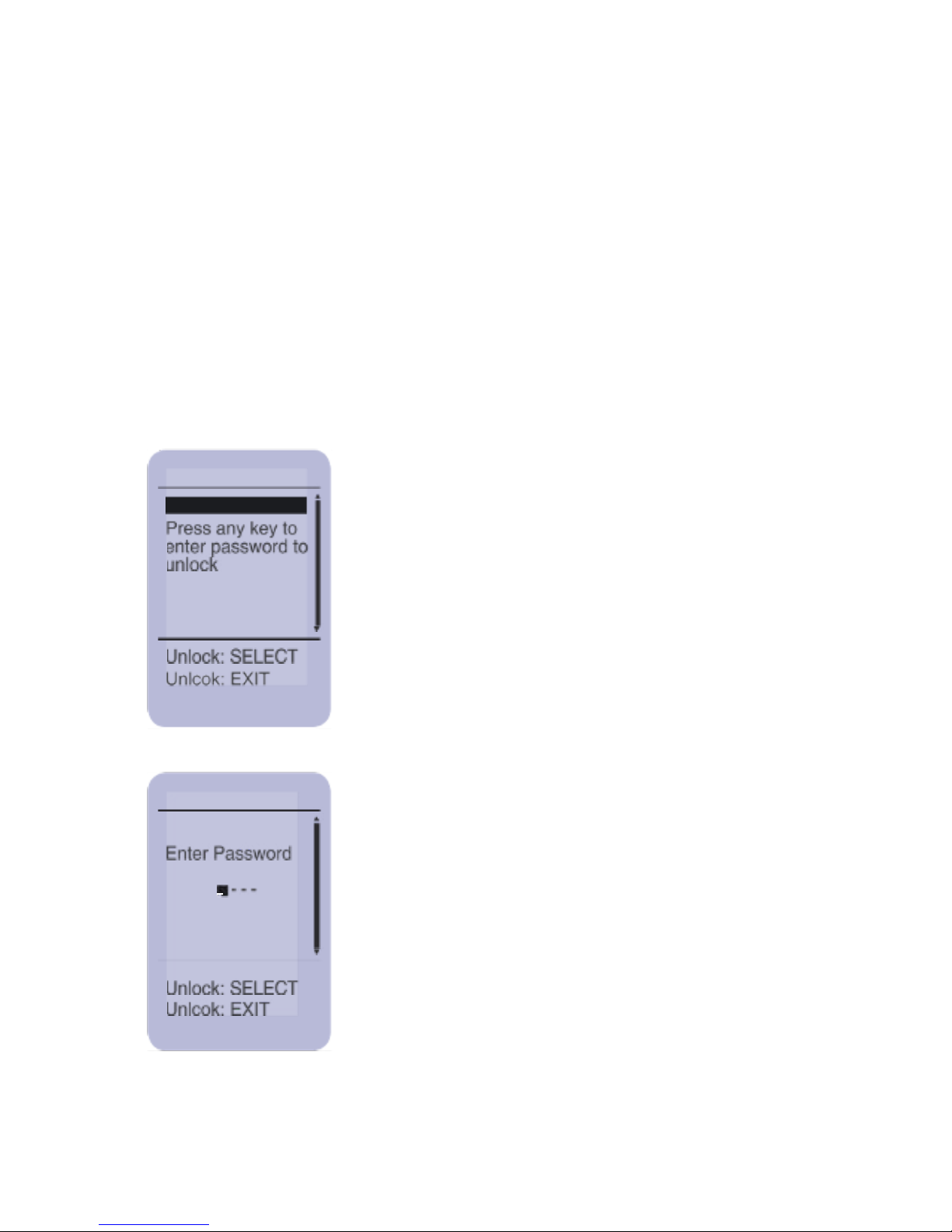
System Lock
Settings
Locked
Unlock Unit
-
This screen is displayed when the system is
locked. You must enter a password to unlock
the unit.
To enter the password, use the UP/DOWN
buttons to scroll through the numbers 0-9.
When you have entered the correct number,
press SELECT. The cursor will move to the
next digit. Repeat until you have entered the
password and
Press SELECT.
The system lock is a software lock that password protects the
system from unauthorized use. You should lock the system
when it is not in use. The default lock password is 0000. If you
change the password, write it down and keep it in a safe place.
If you have lost your password contact Meditech or a Meditech
authorized service center for further assistance.
Page 54
53
Other Screen Shots
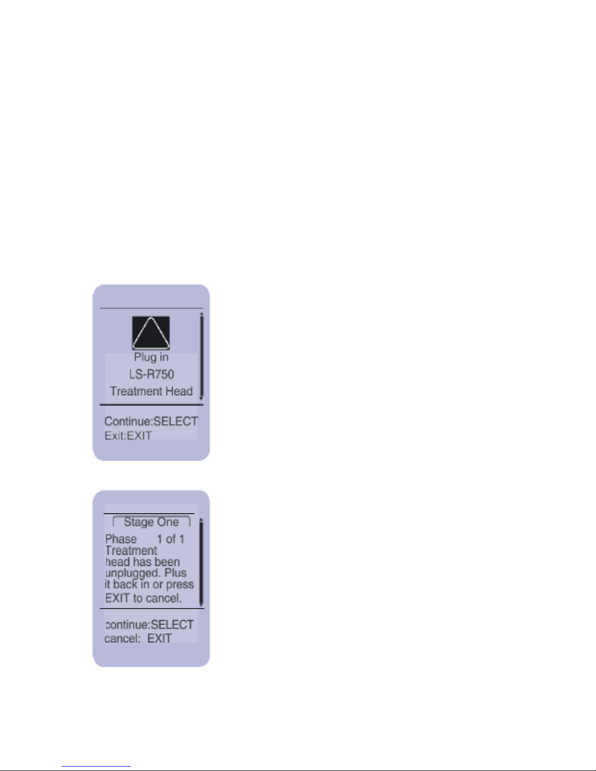
You will see the followings screens when the wrong Treatment
Head is plugged into the Controller or if the Treatment Head
becomes unplugged during a treatment.
This screen is displayed when the correct
Treatment Head in not plugged in.
!
Run Treatment
This screen is displayed when the treatment
head is unplugged.
Press SELECT
to
continue with the treatment. Press EXIT to
cancel.
Page 55

54
Environmental Conditions
The system is capable, while packed for transport or storage, of
being exposed for a period of up to 15 weeks within the following
ranges:
• An ambient temperature range of -20˚C to +70˚C (-4˚F to
+158˚F);
• A relative humidity range of 10% to 100% (non-condensing);
• An atmospheric pressure range of 500hPa to 1,060hPa.
• When the system is operated in accordance with the
instructions for use, the following conditions should not be
exceeded:
• An ambient temperature range of 0˚C to +40˚C (+32˚F to
+104˚F);
• A relative humidity range of 45% to 85% (non-condensing);
• An atmospheric pressure range of 700hPa to 1,060hPa.
Page 56
55
Calibration
• Calibration of the system and/or its components can only
be performed at Meditech or at an authorized service
center.
• If any LD-Series Treatment Head indicates repeat
errors, it may need calibration.
• To maintain your arrays and to keep them working at
optimal performance, they should be calibrated
periodically, depending on use.
• The Controller Unit (CU) does not require calibration.
Note: Only Meditech authorized service personnel are able
to calibrate the system properly. Unauthorized changes
to the system may be subject to termination of the warranty
at Meditech’s discretion.
WARNING: No modification of this equipment is
allowed. If this equipment is modified, appropriate
inspection and testing must be conducted by
Meditech’s service personnel to ensure continued
safe use of the equipment.
Page 57

56
Cleaning
• The CU may be cleaned using a damped soft cloth
or a soft disinfectant cloth.
• The arrays may be cleaned with alcohol wipes, a soft
disinfectant cloth, a soft damp cloth and/or alcohol/
cotton swab combinations.
• A soft bristle brush can be used to remove particles
from the LS Series Treatment Array.
• The LD Series Treatment heads may be cleaned with
alcohol wipes a soft disinfectant cloth, a soft damp
cloth and/or alcohol / cotton swab combinations.
• It is recommended that the treatment surface of the
Treatment Arrays be cleaned after each treatment.
• To keep the Treatment Arrays clean from
contaminates from open wounds, etc., use a clear
plastic bag (or plastic wrap) to prevent Treatment
Array contact with the disease area. Treatment
Array Sleeves (covers) can be purchased from
Meditech or a Meditech authorized distributor.
Page 58

57
If the System Becomes Damaged
If part or all of the system is dropped or damaged, check to
determine if it still functions properly. To troubleshoot a system,
perform the following steps:
1. Check all power connections. Make sure all cables are secure
and properly connected.
2. Turn on the CU. If the CU does not work, contact a Meditech
authorized service center for technical assistance.
Liquids from spills or excessive humidity can also damage your
system. If the system becomes wet, perform the following
steps:
1. Immediately unplug all system components from the electrical
outlet.
2. Contact a Meditech authorized service center for assistance.
Page 59

58
Guidelines for Proper Packaging
In order to ship the system, please follow the guidelines
below for proper packaging:
• Use the original packaging that your system arrived in.
• OR use a box with sufficient room for adequate
cushioning material for all sides of the container.
Never exceed the maximum gross weight for the box
(which is usually printed on the bottom lap).
• Properly cushion the contents of your package by wrapping
each item separately. To prevent damage to the
contents, ensure that they are separated from the corners
and sides of the box. Various materials can be used for
cushioning and protection: i.e. air-encapsulated plastic
(bubble wrap), foam-in-place and/or corrugated dividers.
Use enough cushioning material to ensure that the
contents won’t move easily if the box is handled
improperly.
• Make sure to properly close the box. For best results,
use either pressure-sensitive plastic or water
activated paper tape with at least two inches (5cm) width.
Do not use masking tape, cellophane tape, string or paper
to seal the box.
Page 60

59
Error Messages
An error message will be displayed on the CU’s screen whenever
there is a problem with the system. All Treatment Heads are
automatically tested prior to each use.
Error Messages
An error message will be displayed on the CU’s screen whenever
there is a problem with the system. All Treatment Heads are
automatically tested prior to each use.
• Should a fault occur within the Treatment Head, the user will be
informed with a “beep” and a message via the LCD.
• In some cases the operator may proceed with discretion.
• If your system requires service, please contact a Meditech
authorized service center.
Page 61
60
59
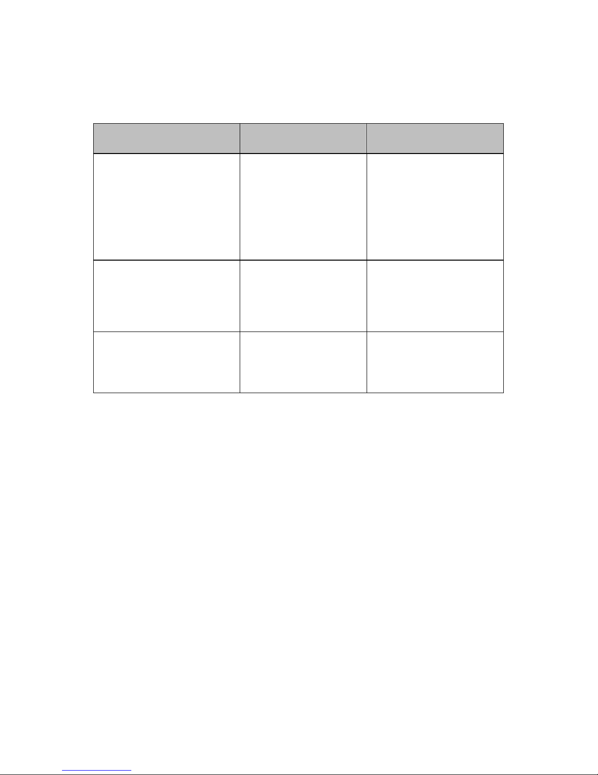
Trouble Shooting Guide
MESSAGES VIA LCD
POSSIBLE
CAUSE
SOLUTION
NO POWER or
DISPLAY IS BLANK
Power supply not
connected.
Power not turned on.
Plug power supply into
hospital grade outlet.
Ensure cable is plugged
into the Controller Unit.
Press POWER button.
LOCKED
Press any key to enter
password to unlock.
System is LOCKED to
avoid unauthorized use.
Each stage of a
treatment specifies a
specific Treatment Head.
Plug in Treatment Head
Incorrect or no
Treatment Head
plugged in.
Identify and plug in
specified Treatment
Head.
Page 62
61
MESSAGES VIA
LCD
POSSIBLE CAUSE
SOLUTION
Head warning
Refer to warning code
L07 in manual
Treatment Head may
be cold compared to
the room temperature
or needs calibration or
is malfunctioning.
All Treatment Heads are
tested prior to each use.
You can still continue to
treat using the Treatment
Head, but use caution.
If this error persists, stop
using the Treatment Head
and send in for service.
Head warning
Refer to warning code
L06, LD8 in manual
Treatment Head may
be hot or needs
calibration or is
malfunctioning.
All treatment heads are
tested prior to each use.
You can
still continue to
treat using the Treatment
Head,
but use extreme
caution.
Ensure that the Treatment
Head is cooled before
continuing in order to
prevent dermal skin
damage. Ask the patient to
inform you if the
Treatment Head
temperature becomes
uncomfor
table or too
warm.
If this error persists, stop
using the Treatment Head
and send in for service.
Page 63
62
MESSAGES VIA
LCD
POSSIBLE
CAUSE
SOLUTION
Head error
Refer to error code
### in manual
Error codes: L01,
D01, D02, D03, L02,
L03, L04, L09
Treatment Head
may need calibration
or is malfunctioning.
Stop treating with the
Treatment Head.
Contact a Meditech
authorized service center
for further assistance.
Provide error code to the
service center.
Send Treatment Head in
for service.
Head warning
Refer to warning
code ### in manual
Warning codes: L05
Treatment Head
may need calibration
or is malfunctioning.
You may continue
treating with the
Treatment Head
If the problem persists
contact a Meditech
authorized service center
for further assistance.
Provide warning code to
the service center.
System failure
Refer to error code
### in manual
Controller Unit (CU)
or Treatment Head
may need calibration
or is malfunctioning.
Stop treating with the
system.
Contact a Meditech
authorized service center
for further assistance.
Provide error code to the
service center.
Send system in for
service.
Unit failure
Refer to error code
### in manual
Error codes: E01,
E02, E03, E10, E11
and E12
Controller Unit (CU)
is malfunctioning.
Stop treating with the
system.
Contact a Meditech
authorized service center
for further assistance.
Provide error code to the
service center.
Send CU in for service.
Page 64
63
Specifications
Controller Unit
Function
Specifications
Mode of Operation
Waveform
Duration
Frequency Settings
Duty Cycle
Percent of Total Power
CW, Waveform
Sine, Square and Triangle
1-60 minutes (1 min resolution)
10-100Hz (10Hz resolution)
250, 500, 1000, 2500,
5000 & 10000Hz
10-90% (10% steps)
10-100% (10% steps)
Function
Specifications
Mode of Operation
Waveform
Duration
Frequency Settings
Duty Cycle
Percent of Total Power
CW, Waveform
Sine, Square and Triangle
0-3600 seconds (1 sec resolution)
10-10000Hz (1Hz resolution)
1-100% (1% steps)
1-100% (1% steps)
Table 1 Controller Unit (Customized Protocol)
Table 2 Controller Unit Specifications
Page 65
64
PARAMETER
UNITS
LD-I 75
LD-I 200
LD-R100
LS-R750
LS-I
1500
Effective laser- LED
class
3B
3B
3B 1 1
Total optical power
mW
75
180
100
750
1500
Effective surface area
cm2
0.10
0.10
0.10
75
75
Power density
mW/cm2
750
1800
750
10
20
Number of devices
1 1 1 179
179
Medium
GaAlAs
GaAlAs
AlGaInP
GaAlAs
GaAlAs
Type
LD
LD
LD
SLD
SLD
Coherence
mm 1 1
N/A 0 0
Wavelength
nm
830
830
660
660
840
Spectral Width
nm
3.0
3.0
N/A
25.0
50.0
Divergence
Deg
9,30
9,30
10,17
8,8
25,25
Device power
mW
75.0
180.0
75.0
4.2
8.5
MPE
18.19W/m2
18.19W/m2
6.36 J/m2 -
Optical density
2.18
2.48
2.03 -
NOHD
cm
0.0
34.3
49.3 -
Table 3 Treatment Head Specifications
Treatment Heads
Page 66
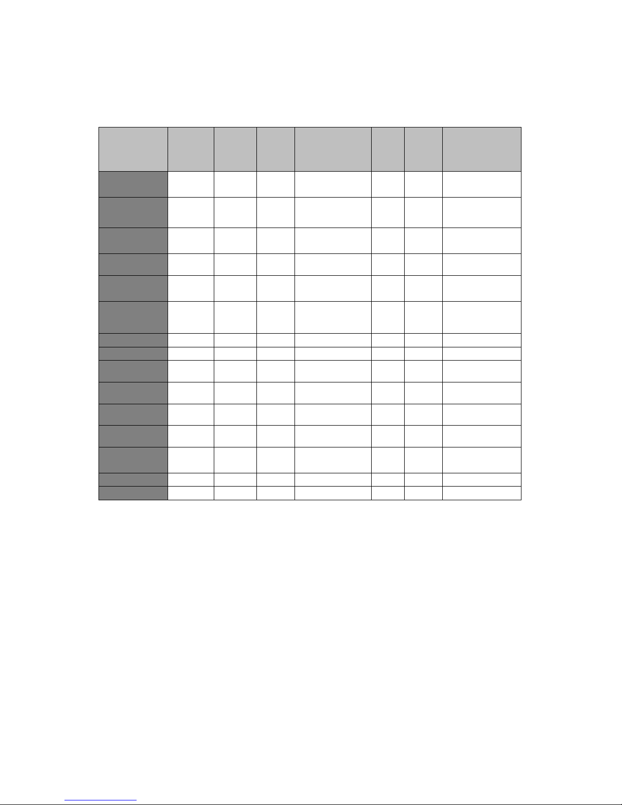
65
PARAMETER
UNITS
LS-R
250
LS-I
500
LS-B3000
SLD-
R50
0
SLD-
I-
1000
LS-B-2250
Effective laser-
LED class
1 1 1 1 1 1
Total optical
power
mW
250
500
1000(red)
2000(infrared)
500
1000
750(red)
1500 (infrared)
Effective
surface area
cm2
25
25
100
77
77
75
Power density
mW/cm2
10
20
10(red)
20 (infrared)
6.5
13.0
10(red)
20 (infrared)
Number of
devices
59
59
240
120
120
180
Medium
GaAlAs
GaAlAs
AlGaInP (red)
AlGaInP (infrared)
GaAl
As
GaAlAs
AlGaInP (red)
AlGaInP (infrared)
Type SLD
SLD
SLD
SLD
SLD
SLD
Coherence
mm 0 0 0 0 0 0
Wavelength
nm
660
840
660 (red)
840 (infrared)
660
840
660 (red)
840 (infrared)
Spectral Width
nm
25.0
50.0
36 (red)
80 (infrared)
25.0
50.0
36 (red)
80 (infrared)
Divergence
Deg
8,8
25,25
12,12 (red)
12,12 (infrared)
8,8
25,25
12,12 (red)
12,12 (infrared)
Device power
mW
4.2
8.5
4.2 (red)
8.5 (infrared)
4.2
8.5
4.2 (red)
8.5 (infrared)
MPE -
Optical density
W/cm2
-
NOHD
cm -
Page 67

66
Glossary
LED Light Emitting Diode
SLD Super Luminous Diode
LCD Liquid Crystal Display
LD Laser Diode
CU Controller Unit
EMC Electromagnetic Compatibility
MPE Maximum Permissible Exposure
NOHD Nominal Ocular Hazard Distance
Page 68
67
Material
Model
Controller Unit
CU
250 mW Red Large Surface Array Treatment Head
LS-R 250
500 mW Infrared Large Surface Array Treatment
Head
LS-I 500
750mW Red Large Surface Array Treatment Head
LS-R 750
1500mW Large Infrared Large Surface Array
Treatment Head
LS-I 1500
1000mW(red)/2000mW(infrared) Large Surface
Array
DUO+ (LS-B 3000)
750 mW(red)/1500mW(infrared) Large Surface
Array
DUO (LS-B 2250)
500mW Red Super Luminous Diode Array
SLD-R 500
1000mW Infrared Super Luminous Diode Array
SLD-I 1000
BioFlex Single Laser LD-I 200
LD-I 200
BioFlex Single Laser LD-I 75
LD-I 75
BioFlex Single Laser LD-R 100
LD-R 100
Carrying Case
BAGT
BioFlex Pro Operational Manual
DOC 100.683
Therapist Clinical Manual
DOC 100.853
Therapist Power supply adapter
CT 100.121
Therapist Power Cord
CT 100.649
Table Fan
CT 100.334
USB Cable
DW 100.650
Treatment Sleeves
CT 100.336
Safety Kit
CT 100.340
Laser safety Guide
Laser Danger Sign
Two Safety Glasses
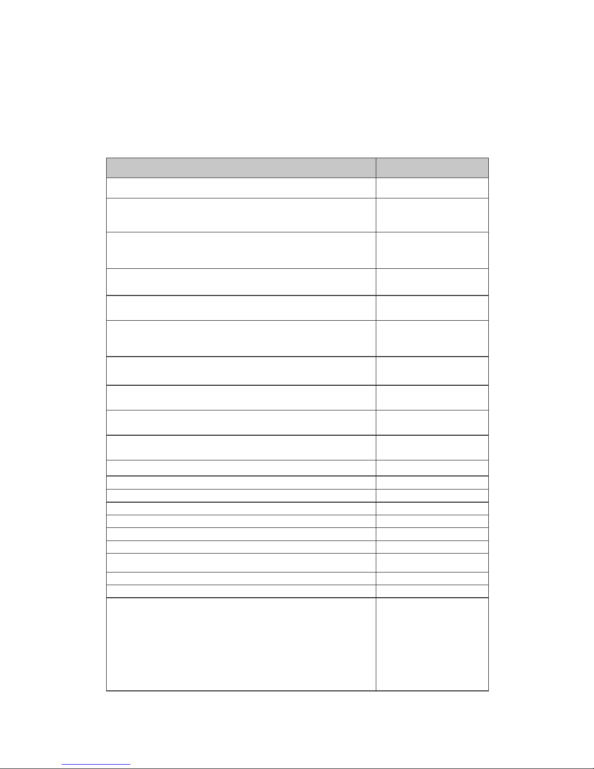
System Parts List:
The items below might not all be supplied with the
system.
Page 69

68
Page 70

69
Page 71

70
415 Horner Ave. Toronto Ontario, M8W 4W3
Phone:(416)251-1055 Fax:(416)251-2446 Toll Free:(888)557-4004
www.biofl exlaser.com info@biofl exlaser.com
copyright©2014 Meditech International Incorporated. ALL RIGHTS RESERVED
MT-ENG-MN-100652
 Loading...