

Page 1
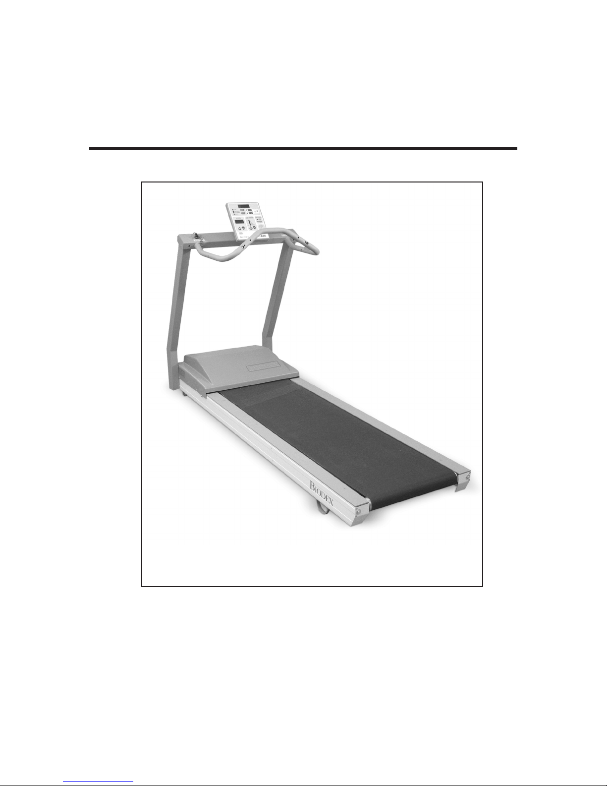
BIODEX RTM 400
REHABILITATION TREADMILL
INSTALLATION/ OPERATION MANUAL
950-275
950-273
950-274
20 Ramsay Road, Shirley, New York, 11967-4704, Tel: 800-224-6339 (Int’l 631-924-9000), Fax: 631-924-9338, Email: [email protected], www.biodex.com
FN: 06-172 Rev A 5/09
BIODEX
Biodex Medical Systems, Inc.
Page 2
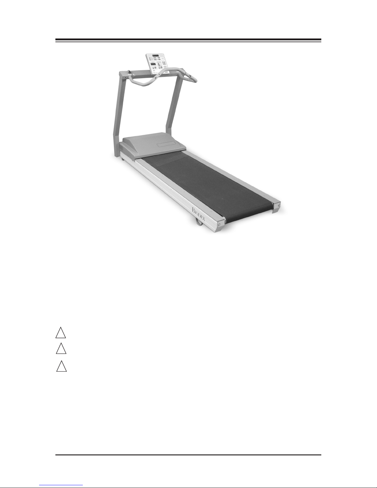
RTM 400 REHABILITATION TREADMILL
!!!
This manual contains installation and operation procedures for the following:
950-275 Treadmill, RTM 400, 115V (includes Support Bar)
950-273 Treadmill, RTM 400, 115V (includes Extended Handrails)
950-274 Treadmill, RTM 400, 115V (includes Pediatric Handrails)
NOTE: The following symbol on your Biodex RTM Treadmill corresponds to the RTM Operation
Manual:
Symbol Signification: Attention, se référer à la notice
Symbol Meaning: Attention, consult accompanying documents
CAUTION: Federal law restricts this device to sale by or on the order of a medical
practitioner. When prescribed for therapeutic purpose, a physician should clearly define the
parameters of use (i.e., total work, maximum heart rate, etc.) to reduce the
risk of patient injury.
CONTENTS — 2—
Page 3

TABLE OF CONTENTS
. INTRODUCTION..............................................................................................................................5
1
2. CLINICAL CONSIDERATIONS....................................................................................................7
3. THE NUMERIC DISPLAY/CONTROL PANEL ..................................................................................9
• Power Up ........................................................................................................................................9
• RTM 400 Numeric Display Control Keys and Functions ........................................................9
4. BASIC OPERATION OF THE RTM 400 ....................................................................................13
• Changing Measurement Units ..................................................................................................14
• Zero Balance Adjustment............................................................................................................14
• Using the RS-232 Computer Interface Port..............................................................................15
5. MAINTENANCE ............................................................................................................................19
• General Maintenance ..................................................................................................................19
• Maintenance Procedures ............................................................................................................20
6. TROUBLESHOOTING ..................................................................................................................23
7. SYSTEM DIAGNOSTICS..............................................................................................................25
• Button Test ....................................................................................................................................25
• Motor Current Test ......................................................................................................................25
8. OPTIONAL..........................................................................................................................................27
• Handrail Installation ..................................................................................................................27
9. CALIBRATION VERIFICATION ................................................................................................29
10. REPLACEMENT ..............................................................................................................................31
11. SPECIFICATIONS ..........................................................................................................................33
12. ASSEMBLY DIAGRAMS AND SCHEMATICS ......................................................................35
— 3— TABLE OF CONTENTS
Page 4

Page 5

1. INTRODUCTION
esigned specifically for rehabilitation purposes, the Biodex RTM 400 Rehabilitation Treadmill
D
provides unparalleled speed control and durability, incline and decline in both forward and
reverse directions, digital feedback, a neat, trim, low profile, a choice of handrail configurations.
An easy-to use numeric display allows the user to get the patient up and moving in a
matter of seconds.
The RTM 400 allows patients to walk, jog and run as they exercise every muscle targeted in their
personalized rehabilitation program. Optional handrail configurations allow clinicians to tailor
the treadmill for various applications including physical therapy/sports medicine, cardiac/pulmonary rehabilitation, geriatric and pediatric conditioning, and use with neurological
patients.
Additionally, 4Q Pulse Width Modulation motor control, the same motor control that helped
make the Biodex Dynamometer the worldwide choice for extremity testing and rehabilitation,
provides more consistent speed control than either AC or DC treadmill models can ever hope to
attain. With track speeds of 0-10 mph (16.9 Km/h) in forward and 0-3 mph (4.8 Km/h) in
reverse, a zero starting speed, the ability to change speeds in .1-mph (.2-Km/h) increments, easy
to read displays and touch-key operation, PWM motor control and a choice of handrail configurations, the RTM 400 is among the safest and most versatile treadmills available today.
— 5— INTRODUCTION
Page 6

Page 7
2. CLINICAL CONSIDERATIONS
!!!
. All patients should consult a physician before beginning any rehabilitation program.
1
Tous les patients doivent voir leur médecin responsable avant d'entreprendre la séance de
rééducation.
2. Instruct patient on proper use and all treadmill safety features before beginning exercise.
Expliquer au patient la bonne utilisation des systémes de sécurité du tapis avant de démarrer
la séance.
3. Always attach the Safety Lanyard to the patient's clothing before allowing
treadmill exercise to begin.
Connector toujours la sangle de sécurité aux vêtements du patient avant que
le patient ne commence à travailler.
4. Ensure patient has stretched and warmed up prior to starting treadmill exercise.
Vérifier que la patient s'est échauffé et a fait des étirements avant de commencer
l'entraînement sur le tapis.
5. Do not allow any patient to exercise unattended on the treadmill. Never leave the treadmill
running while unattended.
Ne pas laisser le patient seul sur le tapis pendant la séance. Ne jamais laisser le tapis tourner
sans patient et sans surveillance.
6. Periodically monitor the heart rate of any patient that is exercising on the treadmill.
Surveiller de temps à autre la fréquence cardiaque du patient pendant la séance.
7. Begin all treadmill exercise at slow pace, increasing speed gradually to patient tolerance or
exercise goal. Always inform the patient immediately prior to increasing or decreasing treadmill speed or elevation.
Démarrer les protocloes à une vitesse lente et augmenter progressivement la vitesse en fonction de la tolérance du patient et des objectifs de la séance. Signaler avant de l'appliquer tonte
augmentation ou diminution de vitesse ou d'inclinaison.
8. If reversing treadmill direction, bring the treadmill to a complete stop and inform patient that
the treadmill will begin moving in the opposite direction.
Avant de changer la direction de déplacement du tapis, arrêter le tapis complétement et expliquer au patient que le tapis va démarrer dans le sens opposé.
9. Immediately discontinue exercise if patient feels faint, dizzy or short of breath.
Arrêter la séance immédiatement en cas de dyspnée, d'étourdissements ou d'autres signes de
malaise
— 7— CLINICAL CONSIDERATIONS
Page 8

CONTENTS
0. Never allow anyone to step onto the treadmill while the treadbelt is in motion.
1
Always stop the treadmill prior to allowing the patient to step up onto the treadbelt.
Ne jamais faire monter personne sur le tapis pendant que le tapis est en marche. Arrêter to
jours le tapis avant que le patient ne s'y positionne.
11. Instruct patients to use the handrails when first learning to walk on the treadmill.
Donner la consigne au patient d'utiliser les barres horizontales lors de sa premiére
séance sur le tapis.
CLINICAL CONSIDERATIONS — 8—
Page 9

3. THE NUMERIC DISPLAY/CONTROL PANEL
he Biodex RTM 400 with Numeric Display provides a simple-to-use, easy-to-read, no-nonsense
T
approach to treadmill exercise. Real time readings are displayed for Time, Distance, Calories and
MET values. At the touch of a key, users can select speed, elevation and belt direction, or set an end
time for exercise duration.
POWER-UP
To provide power to the treadmill, ensure the power plug is connected to an appropriate socket.
Press the ON/OFF switch, located on the base of the treadmill in the left corner at the front end,
to the “l” (ON) position. All display windows should illuminate to indicate that power to the
treadmill is ON and the display is active.
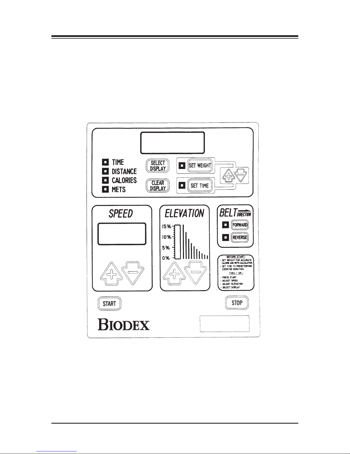
RTM 400 NUMERIC DISPLAY PANEL CONTROL KEYS AND FUNCTIONS (See Figure 1.)
<Start>: Pressing the <Start> key with the treadmill ON activates the treadbelt and clock, and
commands the system to begin gathering data with commencement of the exercise session.
Initial starting speed for treadbelt movement in either forward or reverse direction is 0 mph.
Speed can be increased or decreased in .1 mph increments.
<Stop>: Press <Stop> at any time to ramp the treadmill to a complete stop. All data on the
screen will be retained. At this point, you can press <Clear Display> to end the session and
immediately clear all data, or press <Stop> to end the session but retain all data for 90 seconds
before it is cleared.
<Speed>: Use the <Speed> <+> and <-> control keys on the left side of the display to adjust the
speed to the desired level. The speed will immediately respond to your input so be sure to
inform the patient that the treadbelt will begin to accelerate or decelerate. Gathering of data
begins immediately at the point from which the treadmill begins to move in either forward or
reverse direction.
<Elevation>: If incline or decline is desired, use the <Elevation> <+> and <-> control keys in the
middle of the display panel to set the appropriate grade. Incline and decline can range from 0 to
15% grade. Note that there is a slight delay between movement of the Elevation display bar and
the actual movement of the treadmill.
<Belt Direction>: Treadmill belt direction is selected via the <Forward> or <Reverse> keys. Belt
direction can be changed only when speed is set to 0 speed. If you try to change direction while
the treadbelt is moving, the system will automatically ramp down to 0 speed and wait for further input. For reverse direction, a minus (-) sign precedes the speed value. An orange LED
denotes the selected belt direction.
<Select Display>: The <Select Display> key, located at the center of the control panel’s top section, is
used to determine which parameter will be displayed as data is acquired. All parameters are listed
to the left of the <Select Display> key. An LED denotes the currently active parameter. Once you
press the <Start> key, the display will scroll through the parameters, showing each for a 15-second
interval before moving onto the next. An LED, to the left of the currently displayed parameter,
denotes the active selection. To constantly display a single parameter, use the <Select Display> to
rotate through the parameter list and make your selection after the treadbelt has begun to move.
— 9— NUMERIC DISPLAY/CONTROL PANEL
Page 10

CONTENTS
or all parameters, immediate biofeedback is provided in numeric format for the selected
F
parameter, as described below:
• Time: Cumulative time in minutes/seconds from the point at which the treadbelt begins to
move in either direction.
• Distance (Miles/Kilometers): The distance covered in miles or kilometers from the beginning
to the end of the current exercise session.
• Calories: Total calories burned by the user during the current exercise session. This value is
cumulative.
• METs: The METs value reflects the resting rate of Oxygen consumption with one MET equal to
the Oxygen consumption of a seated individual at rest. Thus, a seated individual in a resting
state is consuming 1 MET. A seated individual exercising at a rate of 2 METs is consuming
twice the Oxygen of a seated, resting individual. A person exercising at 10 METs is consuming
ten times the Oxygen of a seated, resting individual. To compute the METs of a person actively
exercising on the RTM 400 Treadmill, the system uses standard calculations based on
American College of Sports Medicine Guidelines for Testing and Exercise. On the RTM 400
Treadmill, the MET’s value is always displayed in real-time for current speed.
<Clear Display>: Pressing this key immediately clears the system of all acquired data and resets
all display parameters to their default settings.
<Set Weight>: Press the <Set Weight> key to display the default weight setting of 150 pounds. To
alter the default setting, use the <+> or <-> keys on the right side of the display. The set weight
parameter is used to calculate Calories.
<Set Time>: Press the <Set Time> key to display the default time setting of 15:00. To alter the
default setting, use the <+> or <-> keys on the right side of the display. Use the Set Time function to provide an end time for exercise duration. Once a time has been entered, the clock will
begin counting down from the point the treadbelt begins to move.
NUMERIC DISPLAY/CONTROL PANEL — 10 —
Page 11
CONTENTS
afety Lanyard and Safety Stop: Disconnecting the Safety Lanyard (to the left side of
S
Display/Control Panel) or pressing the red Safety Stop (to the right side of Display/Control
Panel on the upper frame) at any time will cause the treadbelt to immediately ramp down to a
full stop and reset to 0.0 mph. The Display will read <Safe> and the treadbelt will not restart
until the lanyard is once again in position or <Start> is pressed following use of the Safety Stop.
Display data is not lost in either case. Data accumulation will resume once the lanyard is reconnected or <Start> has been pressed. To fully abort an exercise session after pressing the Safety
Stop, press <Clear Display>.
Figure 1. The RTM 400 Numeric Display/Control Panel.
— 11 — NUMERIC DISPLAY/CONTROL PANEL
Page 12

Page 13

4. BASIC OPERATION OF THE RTM 400
!
!
t this point, the RTM 400 should be ready for operation. To get the treadmill up and running
A
simply follow the procedure below.
1. Ensure that the <ON/OFF< switch, located on the left side of the front base, is set to the “l”
(ON) position. The Numeric Display should be illuminated, indicating that power to the
treadmill is ON.
2. If desired, use the <Set Weight> keys to enter a weight to be used for calorie calculation.
Default value is 150 pounds (68 kg).
3. If desired, use the <Set Time> keys to predetermine exercise duration.
4. Position the patient on the treadmill and explain the exercise routine.
5. Tilt the display panel for patient viewing comfort.
6. Attach the Safety Lanyard at the left corner of the top cross bar which supports the Display
panel. The round end of the lanyard attaches to the unit via a Velcro®brand hook and loop
fastener. The clip end of the lanyard should be attached to the patient's clothing in a way
that does not interfere with the patient's exercise.
NOTA: La déconnexion de la sangle de sécurité (côté gauche du panneau d'affichage et de contrôle)
ou l'actionnement du bouton rouge d'arrêt d'urgence (côté droit du panneau d'affichage et de contrôle) entraîneront à tout. moment l'arrêt progressif du tapis et le réglage de la vitesse à 0.0 kn/heure.
L'afficage indiquera qu'il y a eu un probléme de sécurité et le tapis ne redémarrera pas tant que la
sangle ne sera pas bien positionnée. De la même façon, aprés l'arrêt par le bouton d'urgence, le tapis
ne démanera pas tant que le bouton de démarrage ne sera pas actionné. Les données affichées ne seront
perdues ni dans l'un ni dans l'autre cas. L'enregistrement des données reprendra une fois la sangle
sera reconnectée et que le bouton de démarrage aura été actionné. Pour arrêter complétement une
séance aprés un arrêt de sécurité, appuyer sur la touche commande d'effaçage.
NOTE: Disconnecting the Safety Lanyard (to the left side of Display/Control Panel) or pressing the
red safety Stop (to the right side of Display/Control Panel on the upper frame) at any time will cause
the treadbelt to immediately ramp down to a full stop and reset to 0.0 mph. The Display will read
<Safe> and the treadbelt will not restart until the lanyard is once again in position or <Start> is
pressed following use of the Safety Stop. Display data is not lost in either case. Data accumulation
will resume once the lanyard is reconnected or <Start> has been pressed. To fully abort an exercise
session after pressing the Safety Stop, press <Clear Display>.
7. Select treadbelt direction using the Treadbelt Direction <Forward> or <Reverse> keys.
8. Press <Start> to enable treadbelt movement.
9. Use the Speed <+> and <-> keys to adjust the speed to the desired level. The speed will
immediately respond to your input so be sure to inform the patient that the treadbelt will
begin to accelerate or decelerate. Gathering of data begins immediately at the point from
which the treadmill begins to move in either forward or reverse direction.
— 13 — BASIC OPERATION OF THE RTM 400
Page 14

CONTENTS
0. If incline or decline is desired, use the Elevation <+> or <-> keys to set the grade at which
1
you wish the exercise to begin.
11. Press <Stop> to stop the treadmill at any time while still retaining all current data on the
display screen.
AVERTISSEMENT: Appuyer toujours sur la touche ARRET pour interrompre un exercise en cours.
Ne pas appuy er sur la touche ATTENTE anant I'arrét complet du tapis. La touche ARRET antraíne
une décélération progressive et toutes les données sont sauvegaardées. Si on était à appuyer sur la
touche ATTENTE, non seulement on perdrait les données mais ela entraínerait aussi un arrét brutal
du tapis.
CAUTION: Always press <Stop> to stop the treadmill when patient exercise is in progress. Do not
press <On/Standby> to clear the system of data until the treadmill belt has completely stopped moving. The <Stop> key will cause the
treadmill to ramp smoothly to a stop, all display data will be retained. Pressing <On/Standby> will
clear all data from the display and stop the treadbelt more abruptly.
12. Press <Clear Display> to clear display data and reset settings to their default values.
13. At the end of the day, turn OFF power to the treadmill using the ON/OFF switch located
on the left side of the front base.
NOTE: BELT MOVEMENT WHILE AT ZERO SPEED
Inherent “belt creep” is common with Pulse Width Modulation Motor Control. Allow the treadmill sufficient time to “warm up” prior to making any adjustments for belt creep. See “Zero Balance Adjustment”
later in this chapter for instructions on this adjustment.
CHANGING MEASUREMENT UNITS
The Biodex RTM 400 can be configured to display either standard English or Euro (metric) measurements. To change measurement units:
1. Turn the treadmill OFF and then ON.
2. While the LED’s on the front panel are lit, press <Stop> and the <Elevation +> key
simultaneously.
3. Depress the <Set Time +> key and units will toggle from Euro (Metric) to English.
4. Once the desired units have been selected, press <Start> to save the new value.
ZERO BALANCE ADJUSTMENT
This option is used to correct treadbelt “creeping” which may occur at the zero speed setting
due to changes in temperature, heavy use, etc.
1. Turn the treadmill OFF and then ON.
2. While the LED’s on the front panel are lit, press <Stop> and <Forward> simultaneously. The
display window should now show a “Creep Adjust-ment Setting” of between 1 and 16.
The factory preset default value is 8.
3. Use the <Set Time> or <Set Weight> key to increase or decrease the Creep Adjustment
Value. Lower the value for reverse direction, raise the value for forward direction.
4. Once the treadbelt has stopped creeping, press <Start> to save the new value.
BASIC OPERATION OF THE RTM 400 — 14 —
Page 15

CONTENTS
SING THE RS-232 COMPUTER INTERFACE PORT
U
The RTM 400’s Remote RS-232 Serial Port can be configured through hardware jumpers on the
display circuit board as follows:
1. RS-232 for single treadmill with single host PC COM: Port
2. RS-422 for multiple treadmills attached to a single PC COM port.
• Treadmills are connected with a single “daisy chained” cable. A multi-drop protocol is used.
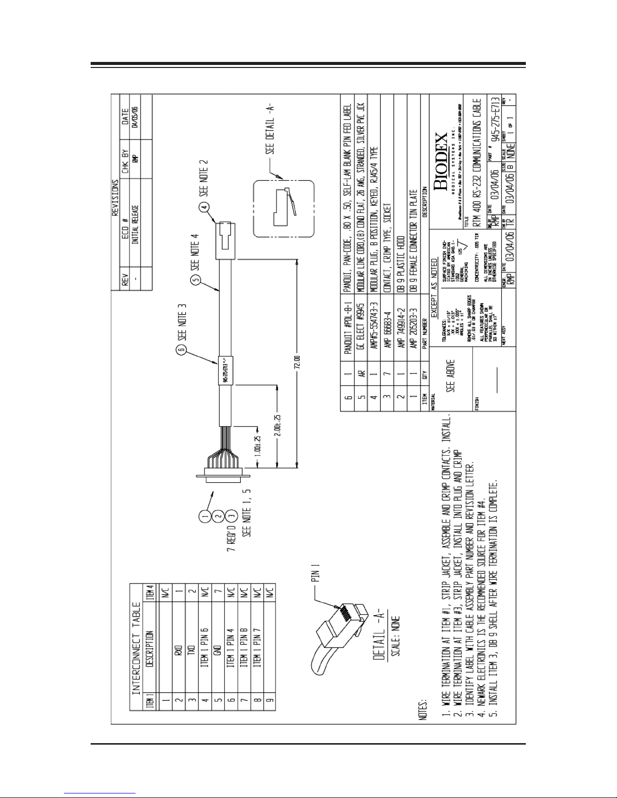
• 9 PIN D Connector: PIN 2 is XMIT, PIN 3 is RCV, PIN 5 is GND 9600 BAUD, no parity, 8 data
bits, full duplex (See Assembly & Schematic Section for RS-232 Communications Cable diagram)
Protocol
The host PC will be the master and initiate all commands. The RTM 400 should process and
acknowledge each command immediately.
— 15 — BASIC OPERATION OF THE RTM 400
Page 16

CONTENTS
ommand
C
(from host): Description Response (to remote host)
F0H to FFH Reserved for multi-drop
device addresses if selected
9FH Who are You 96H, ASCII 4
Single RTM3plus (RS-232)
96H, ASCII 5
Multiple RTM3plus (RS-422)
96H, ASCII 6, RTM3
9EH Firmware Version 9EH, ASCII II “VER_X.XX...”
terminate with NUll = 00H.
80H Start Treadmill 80H to acknowledge
81H Stop Treadmill 81H to acknowledge
82H,ASCII
3 digits Set Treadmill Speed 82H to acknowledge
83H,ASCII
2 digits Set Treadmill Elevation 83H to acknowledge
84H,ASCII
F or R Set Belt Direction 84H to acknowledge
85H,ASCII
3 digits Set Weight 85H to acknowledge
86H,ASCII
4 digits Set Time 86H to acknowledge
Request
RTM Status: Description Response (to remote host)
A0H Read Present Speed AOH, ASCII 3 digits
A1H Read Present Elevation AIH, ASCII 2 digits
A2H Read Present Belt Direction A2H, ASCII F or R
A3H Read Time A3H, ASCII 4 digits
A4H Read Distance A4H, ASCII 4 digits
A5H Read Calories A5H, ASCII 4 digits
A6H Read METs A6H, ASCII 4 digits
A7H Read System Status A7H, 3 hex bytes
Comm. Status Byte
System Status Byte 1
B0H Send one complete packet Send “A1H - AFH”
of status
BIH Send status continuously
B2H Read Set Time B5H,ASCII 3 digits
B3H Read Weight B7H,ASCII 3 digits
BASIC OPERATION OF THE RTM 400 — 16 —
Page 17

CONTENTS
f an invalid command is received from the HOST, the peripheral should respond with AFH for
I
NACK. Invalid commands are defined as:
• illegal command code
• unexpected data byte (not proceeded by appropriate command)
• new command received before previous data transmission completed
• data transmission not completed within specified time limit
• H/W ACIA error, i.e. overflow, frame error, etc.
Each peripheral should have a Communications Status Byte as follows:
Remote Communication Status:
(See diagram on page 41)
Bit 0 1 - ILLG illegal command code
0 - OK
Bit 1 1 - UNEXP unexpected data byte (not proceeded
by appropriate command)
0 - OK
Bit 2 1 - NEW new command received before
previous data transmission completed
0 - OK
Bit 3 1 - TIME data transmission not completed within
specified time limit
0 - OK
Bit 4 1 - COMERR H/W ACIA error, i.e., overflow, frame error, etc.
0 - OK
Bit 5 1 - HWFLT system hardware fault is disabling
function or system is in diagnostic
mode
Bit 6 1 - RANGE data out of range
0 - OK
Bit 7 0 data transmission, B7 MUST BE ZERO!
System Status Byte 1:
The lower control board error codes:
Bit 0 No Hall Effect Speed Signal
Bit 1 Hall Effect Overspeed Error
Bit 2 Tach Overspeed Error
Bit 3 No Speed From Tach
Bit 4 Grade Potentiometer Out of Range
Bit 5 Amplifier Fault Detect
Bit 6 Safety Lanyard Pulled Off
Bit 7 Communication Fault
— 17 — BASIC OPERATION OF THE RTM 400
Page 18

Page 19

5. MAINTENANCE
our Biodex RTM 400 should provide trouble-free operation as long as the following mainte-
Y
nance procedures are performed. Automatic prompts will appear when specific hours of usage
are reached (see chart below).
NOTE: Without proper maintenance, excessive wear to drive components will occur. To assure troublefree operation, scheduled maintenance must be performed. Failure to adhere to the scheduled maintenance
chart below will void your warranty.
INSTRUCTION HOURS OF USAGE LED DISPLAY CODE
Lubricate Deck 75 P1
Reverse Deck 1,000 P2
Belt Replacement 1,000 P3
Clean Motor and Amp 750 P4
Front Roller Cleaning 375 P5
NOTE: Once the required maintenance has been performed, the RTM 400 maintenance prompt can be cleared
by pressing <Select Display> twice, followed by <Clear Display> twice. The Maintenance Hour Log for the specific prompt displayed will reset to zero.
GENERAL MAINTENANCE
Daily Maintenance
As required, clean all exterior surfaces, upholstery and restraining straps. Specialized vinyl
cleaners or protectants are recommended for upholstery and cushions. Otherwise, use a solution
of warm water and mild detergent.
NOTE: DO NOT use solutions containing ammonia.
Hardware computer components should be wiped clean as needed using a soft rag dampened
with alcohol.
Quarterly: Lubricate Treadbelt and Slider Deck
The Biodex Lubricant Kit is designed to reduce friction between the treadbelt and the slider
deck. It is required for all institutional treadmills. Proper and timely application of the lubricate
will prevent premature failures due to excessive wear and load. Items affected by inadequate
lubrication are the treadbelt, slider deck, motor, and motor controller.
Annually or Every 1,000 Hours: Reverse Exact-Track Bed
Reverse the Exact-Track bed. The treadmill bed is double sided, allowing it to be reversed and used
over. Once both sides have been used, the bed must be replaced.
Annually or Every 1,000 Hours: Replace Treadbelt
Inspect treadmill for cracks or tears. If none are found, continue to use. If any cracks or tears are
apparent, replace treadbelt.
— 19 — MAINTENANCE
Page 20
CONTENTS
AINTENANCE PROCEDURES
M
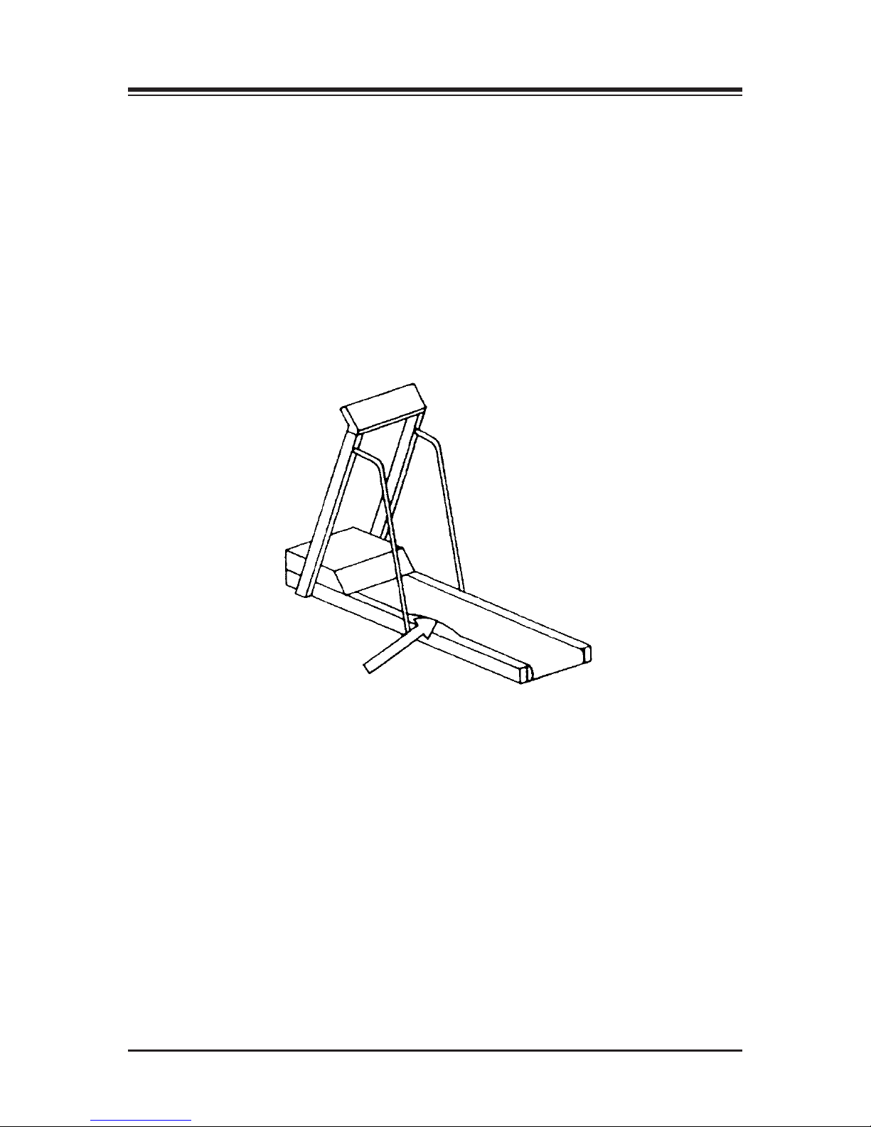
Treadmill Lubrication (See Figure 8.)
1. Squirt one full pipette of the lubricant underneath the center of the treadbelt.
2. Walk 10 steps on the treadmill at a speed of 1.0 mph. This will moisten an 8” track under-
neath the center of the entire treadbelt.
3. Allow the treadmill to dry for approximately 10 minutes.
NOTE: Use only the Biodex lubricant kit with your RTM 400. Most standard greases, waxes and silicon
sprays will build up on the rollers, causing belt slippage and affecting tracking.
To re-order lubricant kit, use Biodex part # 945-276. Each container provides 12 applications.
Figure 8. Squirt one full pipette of lubricant between the belt and deck.
Reverse or Replace Treadbelt and Deck
Tools Required: Phillips Screwdriver, 9/16 Socket, 3/16 and 5/32 Allen Wrenches
1. Elevate treadmill to 10 degrees, allowing access to the underside of the treadmill.
2. Remove power cord from wall outlet.
3. Remove motor cover secured by the six Phillips head screws. Once screws are removed, lift
and remove cover.
4. Remove motor tension lock nut, located on the underside of accessory pan. The nut is
attached to the motor bracket tensioning bolt. Once the tensioning bolt has been removed, lift
the motor up and remove motor drive belt.
5. Remove the two aluminum traction strips, located one on each side of running deck. These are
secured by four Allen screws located on top of traction strips.
MAINTENANCE — 20 —
Page 21
CONTENTS
!!!
!
. Remove rear treadbelt roller. The roller is secured by two treadbelt tensioning bolts. Once
6
bolts have been removed, lift out the roller assembly.
7. Remove the two Allen screws which secure the front treadbelt roller. The screws are located
on the side of the treadmill.
ATTENTION: Si les boutons de sécurité du rouleau sont retirés, le rouleau chutera. Ne oas
oublier que les rouleaux sont lourds.
CAUTION: When the bolts securing the roller are removed the roller will drop.
Be aware that the rollers are heavy.
8. Remove the running deck. This is done by lifting from the side of the deck and raising the
deck two inches before sliding it out. The running deck is two sided and can be flipped
over and reused once.
9. To remove the treadbelt seven support brackets must be removed. These are comprised of
three angle iron brackets attached by securing nuts, and four running deck support bars
secured by Allen screws. Once all support brackets are removed the treadbelt can be
removed.
10. Tension treadbelt and adjust tracking after you reassemble the treadmill. (See Treadbelt
Adjustment procedure.)
Treadbelt Adjustment
Although the RTM Treadmill incorporates the “Exact Track System,” occasional belt adjustments
are still necessary for correct tensioning and tracking.
Tension Adjustment
ATTENTION: Avant de tester la tension du tapis selon la procédure décrite ci-dessons, méttre le
tapis à l'arrêt et déconnecter le câble secteur. Certaines piéces du tapis peuvent entrainer des
blessures graves. Ne jamais essayer de déterminer la tension sur le tapis pendant que ce dernier est
en mouvement.
CAUTION: Before testing treadbelt tension as described below, turn the treadmill OFF and unplug
the system. Moving parts on the treadmill can cause serious injury. Do not attempt to determine
treadbelt tension while the belt is moving.
The need for tension adjustment is indicated by uneven belt speed or the belt stopping suddenly
upon foot impact. Properly tensioned, the treadbelt will allow the user to slip a hand snugly
under the center of the belt.
Treadbelt tension is adjusted by tightening or loosening the two hex-head, 9/16, bolts at the end
of the treadmill frame. The bolts should be adjusted in 1/4-turn increments, exactly the same
amount, in the same direction. Turn both bolts clockwise to tighten the belt. Turn both bolts counterclockwise to loosen the belt. Failure to turn both bolts equally may affect tracking. One quick
test is to apply hand heel strikes and observe if belt momentarily stops.
— 21 — MAINTENANCE
Page 22

CONTENTS
f belt speed remains constant, this indicates belt is tight. If belt hesitates during heel strikes,
I
additional tightening is required. To check over tightening, set treadmill .5 mph and, while holding rail, resist until belt stops. If drive roller continues to rotate with the belt stopped, further
adjustment is not necessary. If drive roller stops when belt is stopped, belt is too tight. Loosen
belt and recheck.
Tracking
Tracking adjustment is necessary when a pronounced bump appears toward the left side of the
belt, approximately two inches from the left edge. This occurs when the belt works its way out
of the Exact-Track grooves.
To Adjust Treadbelt Tracking:
Tighten the hex tensioning bolt on the side to which the treadbelt has migrated, turn bolt in 1/8
increments clockwise. The treadbelt should slowly move away from the tightened bolt. Once
belt migrates back into roller slot the bump will disappear. At this point, fine tracking adjustment is necessary.
Fine Tracking
Fine tracking adjustment prevents premature wear of the tacking belt rib which rides in the
Exact-Track groove. The belt rib should be centered in the tracking groove. If the rib rides
against the groove wall, a friction point forms causing excessive wear. This adjustment should
be made during preventative maintenance or during belt replacements.
To Adjust Fine Tracking:
Determine which side of the exact track groove the belt rib is riding on. Mark treadbelt tracking
position on deck.
Tighten the hex tensioning bolt on the side the belt is tracking against, belt should migrate to the
opposite side of the groove. Mark the treadbelt tracking position on the deck. You now have two
marks on the deck 1/4" apart. Mark the center position of the marks. This is where the belt
should track. Adjust 9/16 tensioning bolt so that the belt is centered on the mark. Remember the
belt will migrate away from the tension bolt that is adjusted last. Tracking adjustments are done
in forward direction only, at 8 mph.
Check tensioning after adjustment to insure proper belt performance and wear.
NOTE: Motor drive belt should never slip. Check this when you check for tread belt overtightening. If
tread belt drive roller is stopped, motor should also stall. If motor turns, but drive roller is stopped, tighten motor tension bracket located under the mill. Adjust until the motor belt stops slipping.
MAINTENANCE — 22 —
Page 23

6. TROUBLESHOOTING
YMPTOM
S
Treadmill is turned ON and speed control is inoperable (belt not moving).
1. Check for faults on display unit before moving onto step #2:
CODE DESCRIPTION
A1 Motor Amplifier Fault
A2 Upper Board NV Ram Failure
A3 Upper Board PROM
A4 Upper Board RAM
A5 Upper Board Communication Failure RS-232
A6 Upper Board Communication Failure RS-422
A7 Lower Board PROM
A8 Lower Board RAM
A9 Not Used
b1 Lower Board Watchdog Failure
b2 Lower Board Watchdog Disabled
b3 Lower Board Controller Fault
b4 Hall No Speed
b5 Hall Over Speed
b6 Lower Board Loopback Comm Failure
b7 Upper Board Failure
b8 Not Used
b9 Not Used
E1 Grade Failure
P1 Deck Lubrication Maintenance
P2 Reverse Deck Maintenance
P3 Belt Replacement Maintenance
P4 Motor & Amp Cleaning
S1 Tach Overspeed
S2 Tach No Speed
2. If no faults are displayed, check the following:
• Large blue capacitor should measure 170 VOL across terminals.
If OK, proceed to step 3.
— 23 — TROUBLE-SHOOTING
Page 24

CONTENTS
. Speed control signal on motor amplifier should measure .250 VDC per mill per hour E.G.
3
NOTE: Measurement taken at J1, PIN 1 to PIN 2 (ground)
1mph = .250 VDC
2mph = .500 VDC
4mph = 1.00 VDC
8mph = 2.00 VDC
If speed control signals are OK, proceed to step 4.
4. Check Amplifier Output. The Output Terminals are located on top of amplifier and are
designated “m+” and “m-”. The Output voltage should be:
1mph = 32 VAC, 2mph = 52 VAC
NOTE: Remember to use the volts A.C. selection on your meter. The Amplifier is pulse width
modulating, therefore, A.C. scale is required.
If amplifier output is OK, proceed to step 5.
5. Check Motor Resistance. The motor has a winding resistance of 1.3 to 3 Ohms. The
value is dependent on commutation position. If resistance reading is significantly higher
the windings or brush contacts are defective.
To measure resistance turn treadmill power OFF. Place meter lead across terminals
marked “m+” and “m-”. Set meter scale to the lowest resistance selection. Check resis
tance in several commutator positions by rotating motor shaft 9.0 degrees for every one
revolution.
TROUBLE-SHOOTING — 24 —
Page 25

7. SYSTEM DIAGNOSTICS
n the unlikely event of a system malfunction, the following tests may be helpful in pinpointing
I
the problem source.
BUTTON TEST
This will test the functionality of the 14 buttons on the display panel. Listed below is the button
designation and the display window codes displayed during key activation.
To activate the button test turn unit OFF then ON. While all LED’s are lit press <Stop> and the
<Elevation -> buttons simultaneously. All LED’s should go OFF. If an error code is displayed
note error and call Biodex Technical Support for assistance. To test individual buttons use chart
below.
Depress each button to ensure proper operation. As each button is depressed there should be a
corresponding beep.
BUTTON DESIGNATION DISPLAY WINDOW
Select display 1
Clear display 2
Set weight 3
Set time 4
Scroll up 5
Scroll down 6
Speed up 7
Speed down 8
Grade up 9
Grade down 10
Forward 11
Reverse 12
Stop 13
Start 14
MOTOR CURRENT TEST
The test verifies that the system is operating under normal motor current levels. A contributing
factor is excess motor current is proper maintenance. As the friction between the running deck
and belt increases so does motor current. Listed below are typical current levels at specific
speeds.
To activate motor current test turn system OFF and then ON. While all LED’S are lit depress
<Stop> and <Speed -> buttons simultaneously. Using the <Speed> buttons select speed as listed
below to verify motor current values. If motor current value varies by more than 20% refer to
the maintenance section of the manual. If after maintenance is performed motor current value
continues at 20% above listed value, contact Biodex Technical Support for assistance.
SPEED MOTOR CURRENT (AMPS)
8.0 2.0
5.0 1.4
0.0 0.4
-3.0 1.2
— 25 — SYSTEM DIAGNOSTICS
Page 26

Page 27
8. OPTIONAL
ANDRAIL INSTALLATION (OPTIONAL)
H
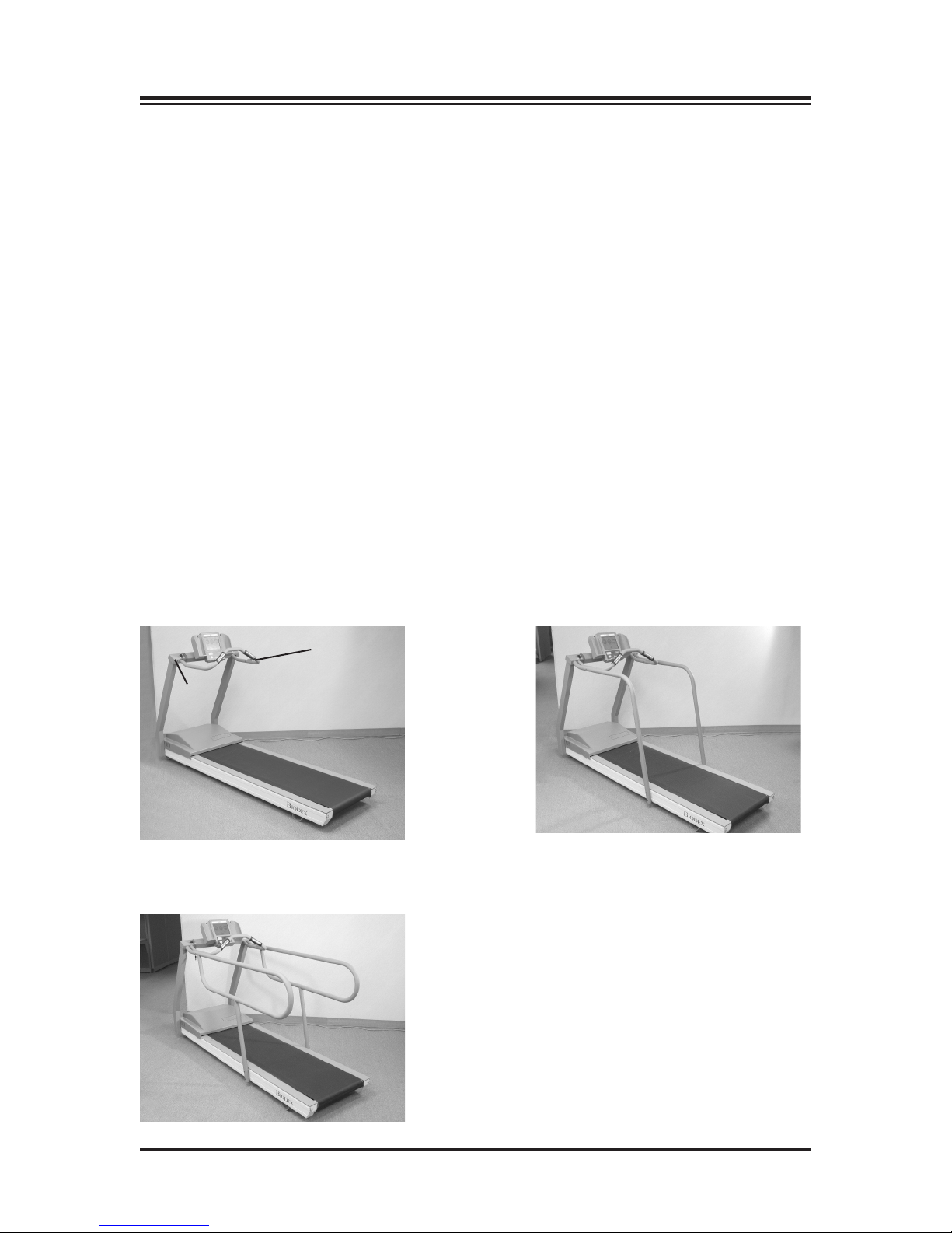
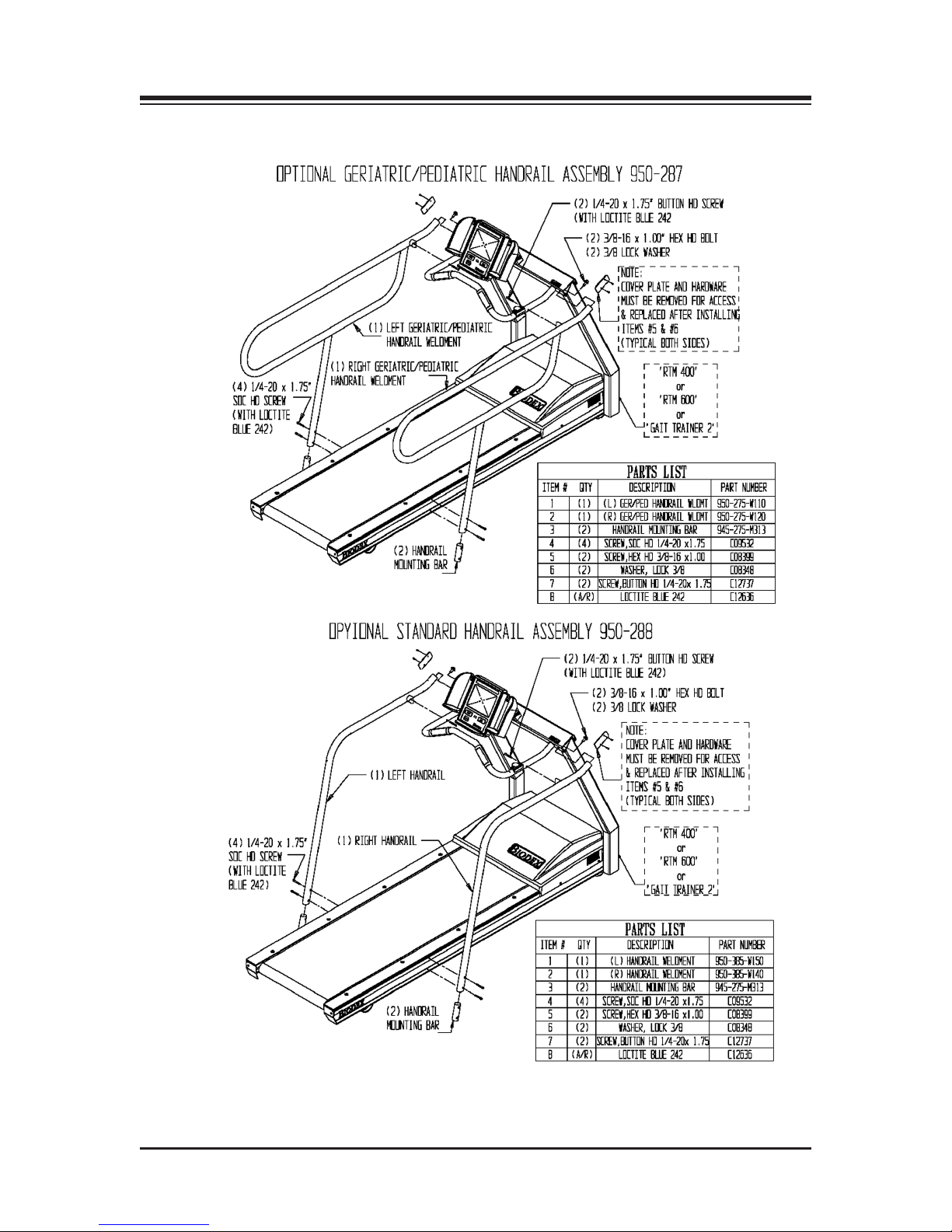
The Biodex RMT 400, RTM 600 and Gait Trainer 2 each come with a sturdy support bar
installed. If desired, customers can install optional Standard Handrails or Geriatric/Pediatric
Handrails. Both optional handrail sets are installed as follows:
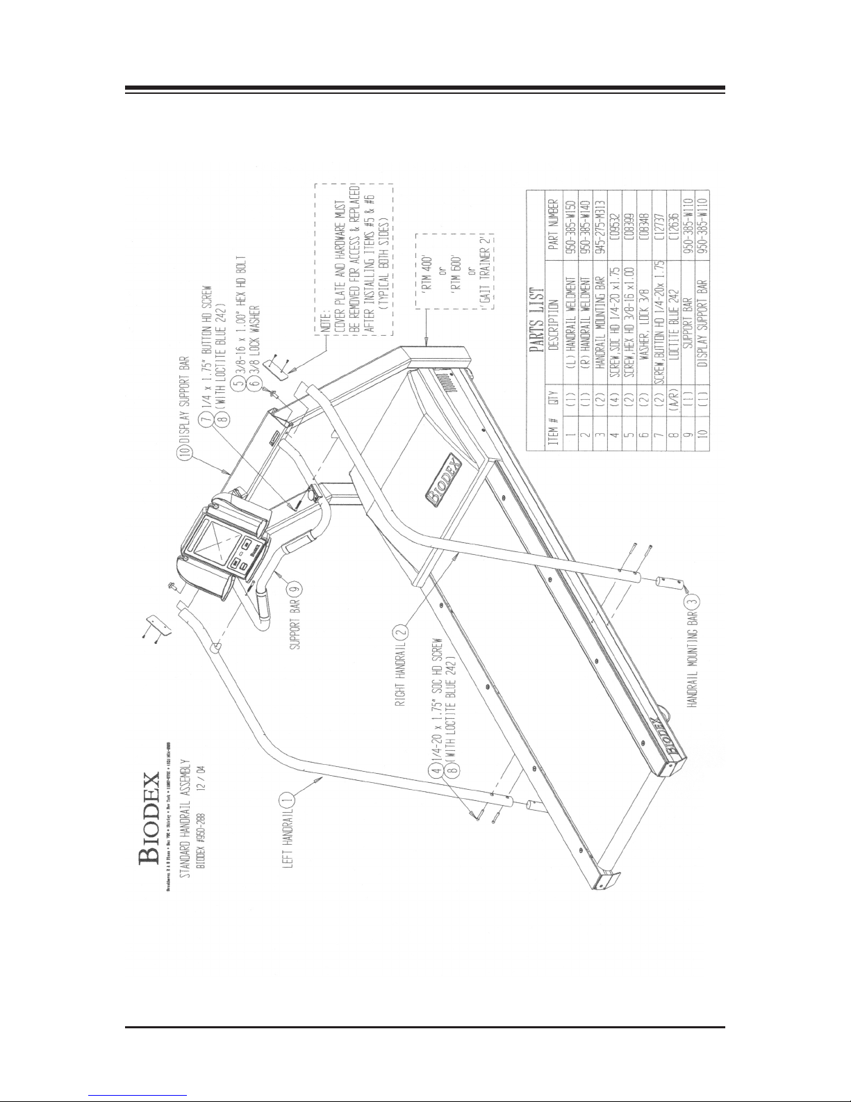
INSTALLATION PROCEDURE
(Refer to Figures 9- 12.)
1. Using a Phillips screwdriver, remove the two screws that attach the cover plate to side of the
display support bar. Set the screws and mounting plates aside.
2. Using a 9/16-inch box wrench, attach the optional handrail to the display support bar with a
3/8-inch lock washer and hex head bolt (leave loose).
3. Insert the handrail mounting bar through the bottom opening of the handrail. Rotate the
mounting bar so that it is aligned with the Allen screw holes and the counter sunk side is
facing out from the treadmill deck. This will prevent the 1/4-20 socket head Allen screw
from protruding outside of the handrail.
4. Attach the bottom of the handrail to the platform deck frame using two 1/4 - 20 x 1.75-inch
socket-head screws (leave loose).
5. Using one 1/4 - 20 x 1.75-inch button-head screw, secure the optional handrail to the support
bar. Pass the screw, threads to the outside of the deck, through the support bar first and into
the optional handrail.
6. Tighten all screws.
7. Using a Phillips screwdriver, replace the cover plate on the display support bar with the two
screws set aside in step #1.
8. Repeat the procedure to attach the opposite optional handrail.
Factory
installed
Support bar
cover plate
support bar
Figure 9. The RTM 400, RTM 600 and
Gait Trainer 2 all come with a factory
installed support bar.
Figure 10. Optional Standard Handrails installed.
Figure 11. Optional Geriatric/Pediatric Handrails installed.
— 27 — OPTIONAL
Page 28
CONTENTS
OPTIONAL — 28 —
Figure 12. Handrail installation.
Page 29

9. CALIBRATION VERIFICATION
his option allows you to verify and calibrate both speed and incline. To activate calibration ver-
T
ification turn unit OFF and then ON. While all LED’s are lit press <Stop> and <Speed +> simultaneously.
To verify speed press <Speed> buttons and select a range of speeds from 1 mph to 10 mph. The
speed display window and selectable display should correspond. If there is a difference, call
Biodex technical Support for assistance.
To verify elevation press <Elevation +> button until incline stops. The selectable display window
should read between 120-128. Press <Elevation -> button until decline stops. The selectable display
window should read between 11-15. If the values displayed are not within the ranges specified call
Biodex Technical Support.
To exit calibration verification depress <Start> for normal operation.
— 29 — CALIBRATION VERIFICATION
Page 30

Page 31

10. REPLACEMENT
tem Number Description
I
ELECTRICAL
945-200-E350 PWM Motor Controller (RTM)
945-250-E700 Treadmill Chassis Harness
945-275-E700 Display Cable Assembly
945-250-E702 115 Volt Actuator Assembly
945-250-E733 Power Cord, Euro
945-250-E703 Power Cord Assembly
945-250-E704 Hall Effects Cable Assembly
945-250-E708 Pulse Width Mod. Cable
945-250-E709 Lanyard Reed Switch Cable
945-250-E711 Position Potentiometer Assy
945-250-E712 Drive Motor with Tach (w/o flywheel)
945-275-E825 Hall Effects PC Board Assy
945-275-E101 Membrane Switch Overlay (LED)
MECHANICAL
C08304 Isolation Transformer
C09456 Relay, Solid State (IEC)
C09102 Circuit Breaker Assy
C09001 Magnetic Sensor
C08986 Poly-V Belt “Type J”
C08992 1 x 2” Dia. Wheels
C08983 Vibration Mounts
945-250-M041 Treadmill Belt
945-250-M036 Bed “Double Groove”
945-275-M314 Rear Foot Brackets
945-275-P058 Enclosure Housing RTM 400
ASSEMBLIES
945-275-A010 Front Roller Assembly
945-275-A020 Rear Roller Assembly
945-250-A090 Safety Lanyard Assembly
945-275-A320 Drive Motor/Flywheel Assembly
945-275-A700 Display, Assy, RTM 400
945-250-A720 Control PC Board Assembly
— 31 — REPLACEMENT
Page 32

Page 33

11. SPECIFICATIONS
imensions: 86" l x 27" w (218 x 69 cm)
D
Running Area: 64" l x 20" w (160 x 51 cm)
®
eck: 1" thick (2.5 cm) reversible Teflon
D
Motor: 2 HP with 4Q-Pulse Width Modulation Control
Speed Range: Forward: 0-10 mph (0-16.9 km/h)
Reverse: 0-3 mph (0-4.8 km/h) in .1 mph (.16 km/h) increments
Elevation: 0-15% grade
mpregnated high density composite fiber
i
Heart Rate
®
Monitoring: Polar
Telemetry (chest strap)
Power: 115 VAC, 50/60 Hz, 20 AMP dedicated line, or 230 VAC, 50/60 Hz, 20 AMP
dedicated line; includes hospital grade plug with 12' (3.7 m) power cord
Patient
Capacity: 400 lb (182 kg)
Weight: 310 lb (140 kg)
Certification: ETL and cETL listed to UL 2601-1, CAN/CSA C22.2 No.: 601-1-M90
Warranty: Two-years parts; one-year labor
— 33 — SPECIFICATIONS
Page 34

Page 35
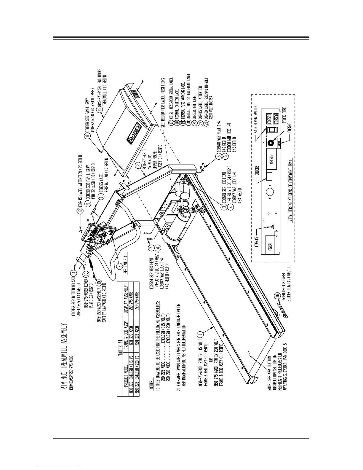
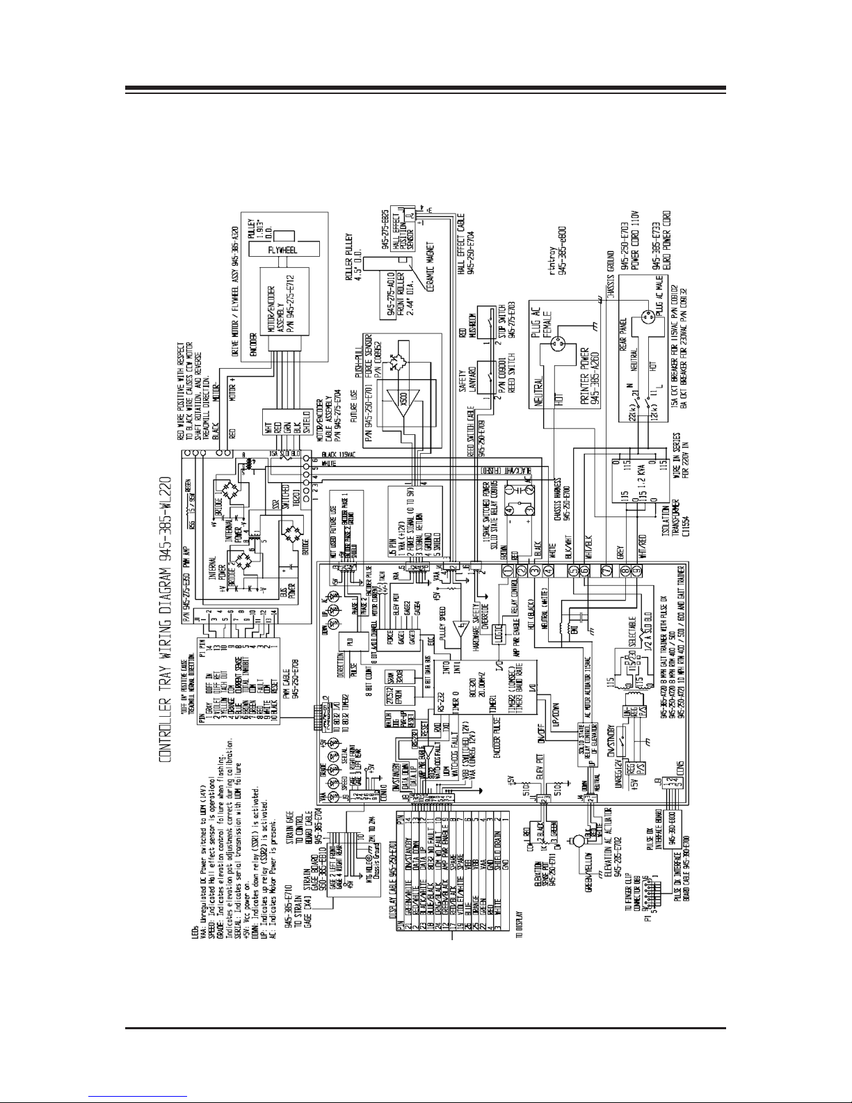
12. ASSEMBLY DRAWINGS/SCHEMATICS
— 35 — ASSEMBLY DIAGRAMS/SCHEMATICS
Page 36
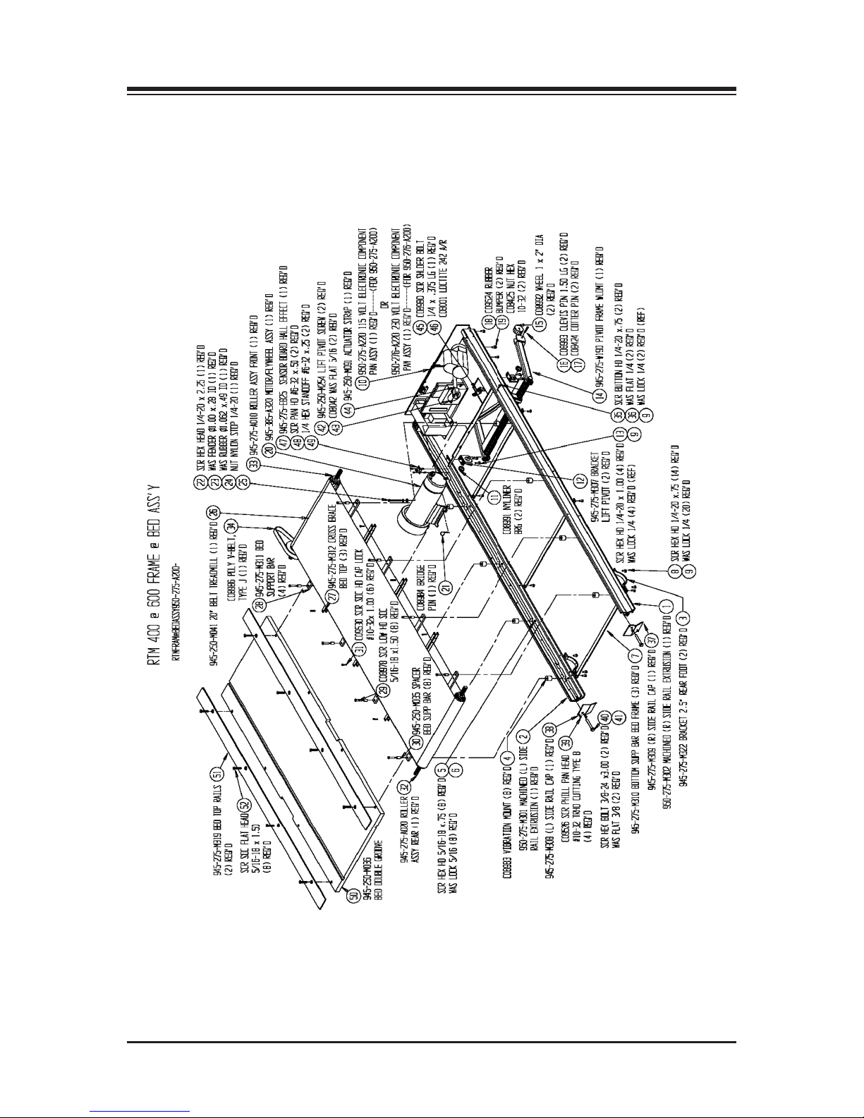
CONTENTS
ASSEMBLY DIAGRAMS/SCHEMATICS — 36 —
Page 37
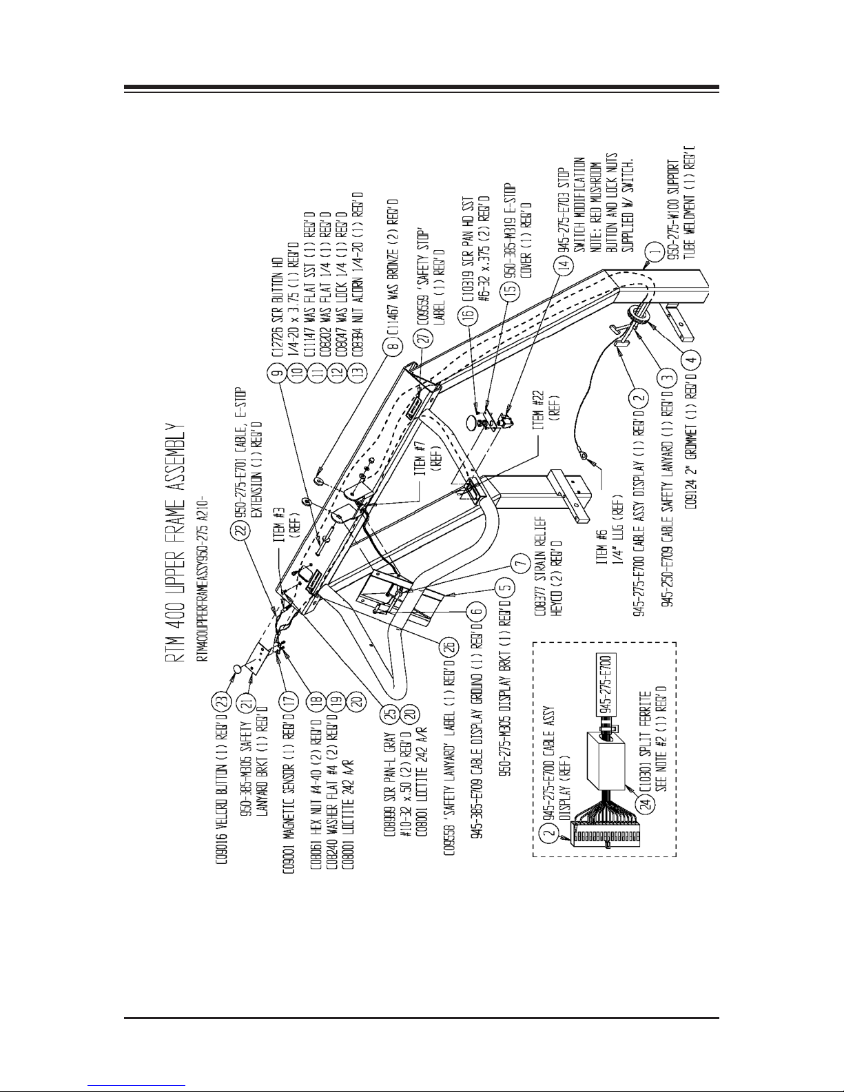
CONTENTS
— 37 — ASSEMBLY DIAGRAMS/SCHEMATICS
Page 38
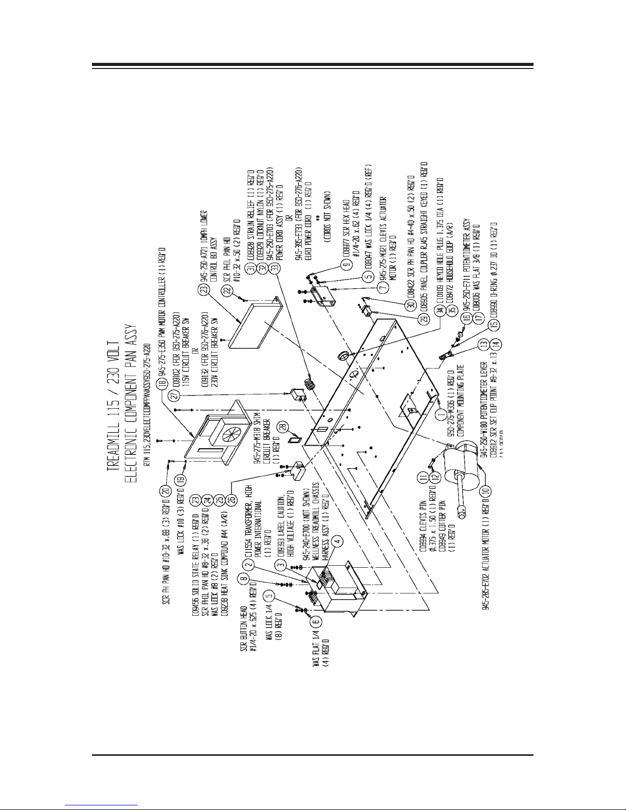
CONTENTS
ASSEMBLY DIAGRAMS/SCHEMATICS — 38 —
Page 39
CONTENTS
— 39 — ASSEMBLY DIAGRAMS/SCHEMATICS
Page 40
CONTENTS
ASSEMBLY DIAGRAMS/SCHEMATICS — 40 —
Page 41
CONTENTS
— 41 — ASSEMBLY DIAGRAMS/SCHEMATICS
Page 42

Page 43

Page 44

20 Ramsay Road, Shirley, New York, 11967-4704, Tel: 800-224-6339 (Int’l 631-924-9000), Fax: 631-924-9338, Email: [email protected], www.biodex.com
Certified Quality Management System
BIODEX
Biodex Medical Systems, Inc.
 Loading...