

Page 1
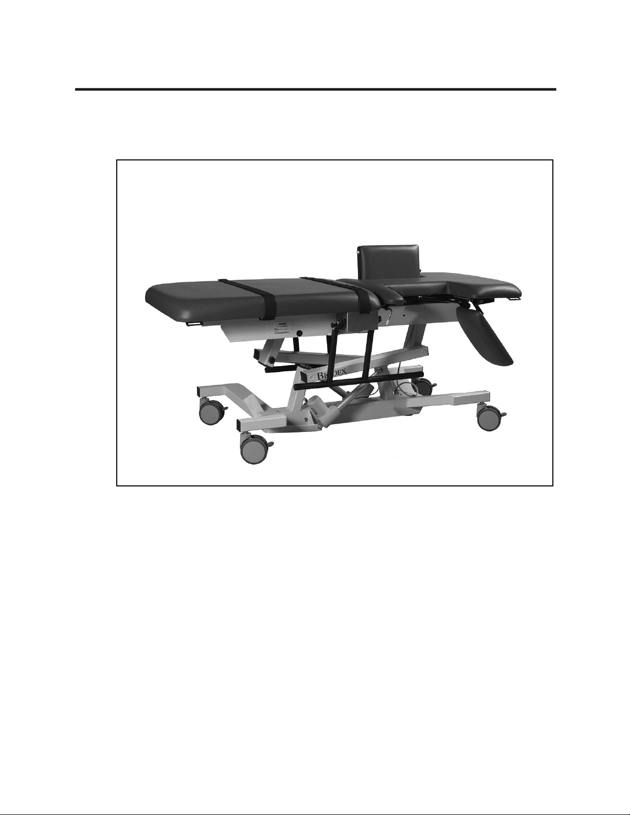
ECONO
ECHOCARDIOGRAPHY
TABLE
OPERATION MANUAL
058-701
058-706
FN: 09-181 Rev C 5/15
BIODEX
Biodex Medical Systems, Inc.
Page 2
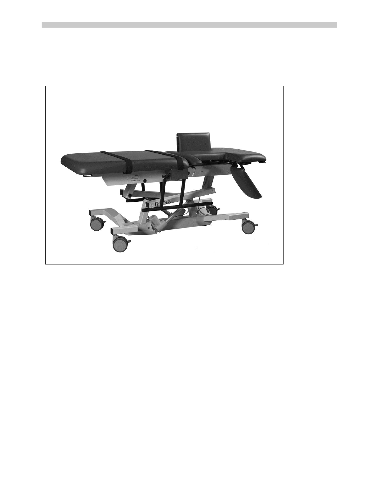
Econo Echocardiography Table
This manual covers operation procedures for the following products:
058-701 Table, Econo Echocardiography, 115 VAC
058-706 Table, Econo Echocardiography, 230 VAC
Page 3

III!
Table of Contents
Definition of Symbols ........................................................... .................................................. IV
Before Proceeding .................................................................................................................... V
Important Safety Information .................................................................................................. VII
Warranty .................................................................................................................................. IX
CHAPTER 1: INTRODUCTION ............................................................................................................................... 1
Intended Use ......................................................................................................................... 1
Indications for Use ................................................................................................................. 1
General Cleaning and Maintenance Instructions ..................................................................... 1
Table Parts and Adjustments .................................................................................................. 2
CHAPTER 2: ASSEMBLY AND TABLE OPERATION ..................................................................................... 3
Relocating the Table .............................................................................................................. 3
Height Adjustment ................................................................................................................. 3
Fowler Back Adjustment ......................................................................................................... 3
Leveling The Table ................................................................................................................. 3
Adjustable Sonographer Cutout Cushion ................................................................................ 4
Cardiac Scanning Cutout ........................................................................................................ 4
Installing and Using Optional Accessories .............................................................................. 5
Articulating Scanning Arm Board ......................................................................................... 5
Side Rails ............................................................................................................................ 6
Headrest Extension ............................................................................................................. 7
Paper Dispenser .................................................................................................................. 8
I.V. Pole ............................................................................................................................... 9
APPENDIX A – SPECIFICATIONS ...................................................................................................................... 10
APPENDIX B - CONFORMANCE TO STANDARDS ....................................................................................... 11
APPENDIX C – PARTS AND ASSEMBLY ILLUSTRATIONS ........................................................................ 15
Page 4

IV!
Definition of Symbols
The following symbols and their associated definitions
are used and implied throughout this manual.
Symbol Definition
Carefully read these instructions prior to use
Caution
General Warning
General Mandatory Action
Dangerous Voltage
“On” Power
“Off” Power
Earth (ground)
Alternating Current
Fuse
USB Connector/Cable
Waste in Electrical Equipment
Date of Manufacture
Type B Applied Part
CE Mark
CE Mark for products with EC Certificate
Certified for Safety by ETL Intertek
Page 5
V!
Before Proceeding
NOTE: The warnings, cautions and instructions provided in this manual must be read,
followed and kept available for consultation at all times. Observing the information,
instructions and procedures presented throughout this manual is essential for using this
product both properly and safely.
SPECIFIC CAUTIONS
• Allow only qualified, trained personnel to operate or service this product.
• If
the equipment is used in a manner other than specified in this operation
manual, the protection provided by the equipment may be impaired and results
could be compromised.
• Nev
er leave patient unattended on table.
EN GARDE SPÉCIFIQUES
• Permettez au personnel seulement autorisé, entraîné de faire marcher ou
assurer l'entretien de ce produit.
• Si l'équipement est utilisé dans une manière autr
e qu'indiqué dans ce manuel
d'opération, la protection fournie par l'équipement peut être diminuée et les
résultats pourraient être compromis.
• Ne
quittent Jamais le patient sans surveillance sur la table.
CAUTION: Unauthorized modifications to this product are not permitted and will void
the manufacturer’s warranty. Unauthorized modification of the product may result in a
hazard to the user and/or patient. Do not modify this equipment without authorization
from the manufacturer.
ATTENTION: Les modifications faites sans autorisation à ce produit ne sont pas
permises et va faire le vide la garantie du fabricant. La modification faite sans
autorisation du produit peut s'ensuivre dans un hasard à l'utilisateur et-ou le patient. Ne
modifiez pas cet équipement sans autorisation du fabricant.
CAUTION: Before moving the table with a patient, make sure side rails are in the up
position and body straps are in place to secure the patient.
ATTENTION: Avant le fait de déplacer la table avec un patient, assurez-vous que les
rails de côté sont dans en haut la position et les courroies de corps dans l'endroit pour
protéger le patient.
Page 6

VI!
Training
This operation manual includes assembly and operating instructions. Operating/assembly
questions can be directed to the service department during business hours.
User Profile
Patient
The product (without accessories) shall accommodate patients fitting the following profile:
Height: From infant to 74 inches (6ft - 2in)
Weight: Up to 500 lbs
Age: Infant to 65 years of age
Sonographer
The product shall accommodate sonographers fitting the following profile:
5th percentile female, 20-65 years of age
95th percentile male, 20-65 years of age
Product Certifications and Classifications
The Econo Echocardiography Table has received the following certifications, and falls within the
following classifications:
• ETL Listed Electrical Equipment, General Requirements for Safety conforms to EN 60601-1,
2nd ED, EN 60601-1:1998, EN 61000-6-1, EN 61000-6-2, EN 61000-6-3, EN 61000-6-4,
EN 60601-1-2, EN 1970, UL 60601-1, 1st ED, 4-25-2003 rev 2006/04/26 and
CAN/CSA C22.2 no.: 601.1M9.
• Type B Applied Part
• Electromagnetic Compatibility: This equipment complies with the medical equipment
IEC60601-1-2 EMC Standard.
Authorized European Community Representative:
EC REP
Emergo Europe
Molenstraat 15
2513 BH, The Hague
The Netherlands
Page 7
VII!
Important Safety Information
CAUTION: Federal Law restricts this device to sale by or on the order of a physician,
sonographer or other licensed professional.
ATTENTION: La Loi Fédérale restreint cet artifice à la vente par ou sur l'ordre d'un
docteur, sonographer ou d'autre professionnel agréé.
Follow the unpacking and assembly instructions document.
Before using this equipment, read the entire operation manual carefully. Failure to read
the manual may result in user error or injury. Be sure to save all provided documents for
future reference.
Make certain to understand all warning and caution labels as explained in the Before
Proceeding section of this manual.
This product should be used only as specified in the operation manual.
Biodex Imaging Tables are designed for use in a patient environment.
Tables Biodex imagerie sont conçus pour une utilisation dans un environnement du
patient.
For product specifications, refer to the Table of Contents.
This medical electrical equipment requires special precautions regarding EMC and must
be assembled and placed into service according to EMC information provided in this
manual. For electromagnetic compliance definition, refer to the Table of Contents.
Reference Cleaning and Maintenance instructions in Table of Contents.
CAUTION: Operation for 058-701: 120 VAC, 60 Hz; 058-706: 230 VAC, 50 Hz.
ATTENTION: Opération pour 058-701: 120 VAC, 60 Hz; 058-706: 230 VAC, 50 Hz.
WARNING: Only use approved power supplies.
AVERTISSEMENT: N'utiliser que les alimentations homologuées
Page 8

VIII!
CAUTION: To avoid risk of electric shock, this equipment must only be connected to
supply mains with protective earth.
ATTENTION: Pour éviter le risque de choc électrique, cet équipement doit uniquement
être connecté à un approvisionnement conduites avec la terre protectrice.
CAUTION: The plug is considered the method of disconnecting the product from main
power. Do not place the product in a position where the plug is not easily accessible.
ATTENTION: Le bouchon est considérée comme la méthode de déconnexion du produit
d'alimentation. Ne placez pas le produit dans une position où le bouchon n'est pas
facilement accessible.
CAUTION: This product is intended to remain in one location during operation. It is
provided with wheels for relocation which should be used when moving the table. Once
positioned, be sure to engage each of the four wheel lock levers to ensure table stability.
ATTENTION: Ce produit est destiné à rester à un endroit pendant le fonctionnement. Il
est muni de roues pour la réinstallation qui devraient être utilisés lors du déplacement
de la table. Une fois positionné, assurez-vous d'engager chacun des quatre leviers de
blocage des roues pour assurer la stabilité de la table.
Page 9

IX!
Biodex Medical Imaging Table Warranty
1. Product Warranty
A. This equipment and its accessories (excluding cushions), are warranted by BIODEX
MEDICAL SYSTEMS, INC. against defects in materials and workmanship for a period of
two years from the date of shipment from BIODEX MEDICAL SYSTEMS, INC. During the
warranty period, BIODEX MEDICAL SYSTEMS, INC. will in its sole discretion, repair
(on-site), send replacement parts or replace the equipment found to have such defects, at
no charge to the customer.
EXCEPT AS STATED ABOVE, THERE ARE NO WARRANTIES, EXPRESSED OR IMPLIED,
INCLUDING WITHOUT LIMITATION WARRANTIES OR MERCHANTABILITY OR
FITNESS FOR
USE. BIODEX DOES NOT ASSUME LIABILITY FOR INCIDENTAL,
CONSEQUENTIAL OR INDIRECT
DAMAGES INCLUDING LOSS OF USE, SALES, PROFITS
OR BUSINESS INTERRUPTION.
B. This warranty does not apply if the product, as determined by BIODEX MEDICAL
SYSTEMS, INC., is defective due to abuse, misuse, modification or service performed by
other than a BIODEX MEDICAL SYSTEMS, INC. authorized repair representative. Misuse
and abuse include, but are not limited to, subjecting limits and allowing the equipment to
become contaminated by fluid materials.
C. In order to obtain warranty repair service and to expedite repair process, please contact
BIODEX MEDICAL SYSTEMS, INC. Support Services Dept. at 800-224-6339, and select
product support as prompted.
2. Warranty is non-transferable.
3. Non-Wa
rranty Service
A. Repairs and/or replacements not covered by this warranty may be performed by
BIODEX MEDICAL SYSTEMS, INC. authorized service representatives.
B. The cost of transportation to and from the service location will be the
responsibility of the customer.
Page 10

X!
Service Procedure
If you think you have a service problem, take the following action:
1. Check to see that the problem occurs more than once.
2. Refer to the instruction manual and operations procedure.
If you still think you have a service problem, call BIODEX MEDICAL SYSTEMS, INC.,
Service Department at (800) 224-6339 and select product service as prompted.
Keep yourself and the phone next to the equipment.
1. Service will ask you for a brief description of the problem. We will ask specific questions about
the malfunction that occurred. This diagnostic process may take a few minutes, so call us when
you can set aside an
uninterrupted block of time.
2. After taking the information, we will advise on the action we will take.
3. Sometimes service personnel must consult with engineering and it may take time to get back
to you. Be sure to let the service representative know your schedule so that we can call at a
convenient time.
4. The
return call may be from a person other than whom you first reported the problem to.
5. After analyzing the problem, we will decide if the unit can be repaired on site, or replacement
parts will be sent.
6. If the unit must be returned, Biodex will provide a return materials authorization number
(R.M.A. #.) Pack the table in the carton that it was originally shipped in. It is the customer's
responsibility for any damage that occurs during shipping.
7. Non-warranty/non-service contract charges for repair are as follows:
a. Materials
+
b. Time
+
c. Travel Zone
Page 11

1!
1. INTRODUCTION
Intended Use
The Econo Echocardiography Table is designed to provide a safe ergonomic environment for the
sonographer and patient. The design features are intended to relieve musculoskeletal stress on
the sonographer while scanning, and to provide the utmost patient comfort.
Indications For Use
The Econo Echocardiography Table is typically used in radiology departments, cardiovascular
facilities, diagnostic imaging centers and private practice clinics to achieve quality images for a
variety of procedures and patient applications.
General Cleaning and Maintenance
1. As required, cleanse all exterior surfaces and tabletop pads with a mild detergent solution
such as Parker Laboratories Protex Disinfectant or any one-step disinfectant that does not
contain bleach.
2. Keep wheel assemblies free of foreign materials and dirt accumulation.
3. Periodically inspect all welds.
4. Periodically check bolts on table, tighten if necessary.
5. Periodically inspect all strap holders. Any holder that feels loose should be removed and
rea
ttached after adding a spot of Loctite® Threadlocker (Blue #242) to the bolt threads. This
should ensure that the bolt will not loosen again in the future.
Page 12
2!
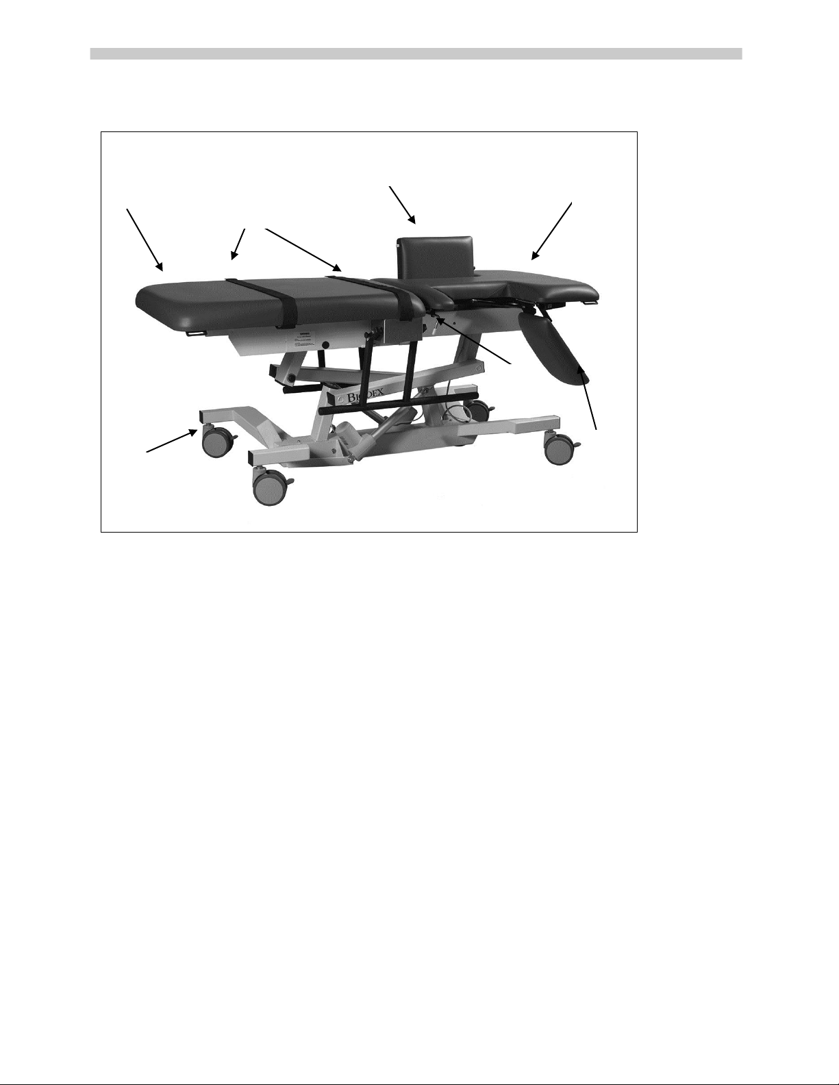
Table Parts and Adjustments
Figure 1. The Econo Echocardiog r aph y Table parts and adjustment include:
Standard Parts and Adjustments:
1. Extra-Wi de Tabletop With 500-lb Patient Capacit
y
2. Re
straining Straps
3. Adjustab l e So no gr ap he r Cut out Cush ion
4. Fowler Back
5. Ca
rdiac Scanning Cutout Cus hi on
6. Cardiac Sc ann ing Cu shi on Re le as e Lev er
7. 5" Locking Swivel Casters
8
. Hand Co
ntroller (Not Shown)
Optional:
058-633 Side Rails, Folding
058-736 Arm Board, Vascular Scanning
058-737 I.V. Pole
058-611 Dispenser, Paper, With Cut t e r S tr a p
058-738 Extension, Headrest
1 2 3 4 5 6 7
Page 13

3!
2. ASSEMBLY AND TABLE OPERATION
Relocating The Table
CAUTION: Before moving the table with a patient, make sure side rails are in the up
position and restraining straps are in place to secure the patient.
ATTENTION: Avant de déplacer la table avec un patient, assurez-vous que les rails
latéraux sont dans les courroies hautes de position et de corps en place pour fixer le
patient
This table can be easily moved across smooth surfaces.
To move the table, release each of the four individual wheel lock levers by lifting up on the end of
each lever with your foot.
Once positioned, depress the end of each individual wheel lock lever to lock the table in
position, ensuring stability.
Height Adjustment
Table height is conveniently adjusted with the hand-held controller. D-ring holders are provided
on the end of the straps at each side of the table frame to hold the hand-held
controller when it is not in use. The hand-held controller can be moved to either
side of the table. A power light on the controller indicates that power from the
control box is on.
• To raise the table: press and hold down the table UP bu
tton.
• To
lower the table: press and hold down the table DOWN button.
NOTE: The control box, located underneath the tabletop, is labeled with controller
specific information.
Fowler Back Adjustment
The motorized Fowler back is infinitely adjustable to 80° via the hand-held
controller.
Leveling The Table
The table has a self-leveling feature which can be used when the table is in a seated position.
• To level the table, press and hold both Fowler back buttons on the hand-held control.
Figure 2.
Hand-held
Controller
activates table
positions.
Page 14

4!
Adjustable Sonographer Cutout Cushion
To assure both patient and sonographer comfort, the adjustable sonographer cutout cushion
can be fully lowered or raised to either of two positions.
• To fully lower the cushion, reach under the cushion and squeeze together the two
sonographer cutout cushion release handles. This will release the cushion, which can now be
lo
wered. To return the cushion back to the level position, squeeze the handles together and
lift up on the cushion until it is higher than level and t
hen lower the cushion back down until it
locks in the level position.
• To raise the cushion, lift up on the cushion. There are two positions in which the raised
c
ushion can be set. To set the cushion in the first raised position, lift the cushion two-thirds of
the way to vertical and then allow it to slide back down slightly until you feel it lock into
position. To raise the cushion to the fully raised position, lift the cushion all the way up to
vertical and then allow it to move back slightly until it locks into place. To lower the cushion
from either raised position, lift up on the sonographer cutout cushion release lever (locate
d
along the head-e
nd of the cushion) and then lower the cushion.
Cardiac Scanning Cutout
The cardiac drop-down cushion can be released by pressing the yellow release handle which can
be found toward the lower end of the Fowler back section on each side of the table.
The cushion can be returned from either side of the table. From the right side you will find a
handle located toward the head end of the table. By pressing this handle down, the cardiac
cushion will return to level. From the left side of the table, simply push the cushion back up to
level
Page 15
5!
Installing And Using Optional Accessories
NOTE: The tools needed to install all table accessories are provided with the table. These include
a 7/16" wrench, a 9/16" wrench and a Phillips screwdriver.
Articulating Scanning Arm Board (058-736)
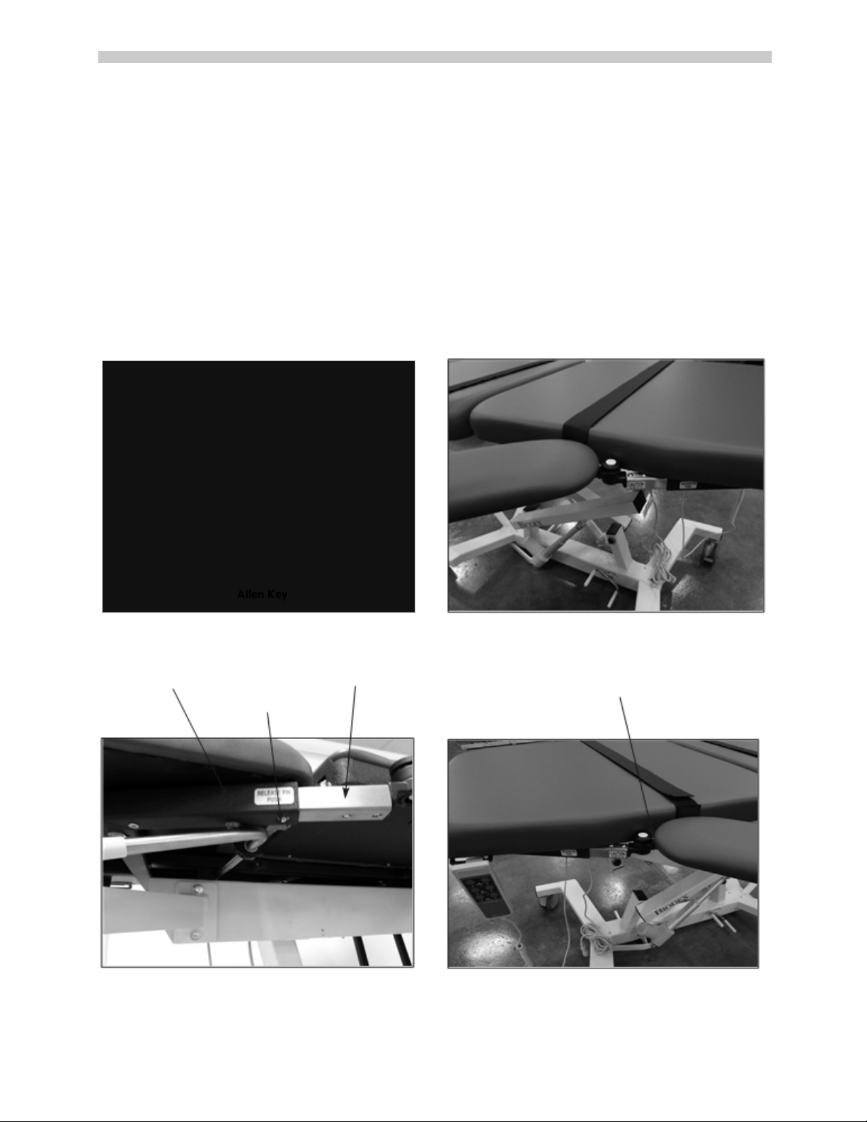
The optional Articulating Scanning Arm Board is installed by inserting the arm board tube into
the receiving tube located on each side of the table below the Fowler back section. The arm
board pivot is adjustable at any point along its 130° arc. To adjust, press the yellow button on
the arm board and move to the desired location; release yellow button. (See Figures 3 - 6.)
To remove the arm board, press the release button beneath the receiving tube and pull to remove.
Compensator
Allen Key
Receiving Tube
Arm Board Tube
Angle Adjustment Knob
Release Button
Figure'4."The"articulating"scanning"arm"board."
Figure'3.'
Figure'5.'
Figure'6.'
Adjustment Screw
Adjustment Screw
Page 16

6!
Side Rails (058-633)
The optional side rails can be installed on both sides of the table. Each rail pivots individually to
either the raised or lowered position. Two rails are supplied; one for each side of the table.
To install the side rails:
1. Using a 7/16" wrench, remove the four 1/4-20" hex head screws from under the abdominal
cushion (toward the rear of the cushion) on the side of the table to which the side rail will be
installed. Remove the strap bracket and save the screws to reinstall in step 3.
2. Position the side rail support bracket against the bottom of the cushion so the four pre-drilled
screw holes in the bracket align with the screw holes under the seat cushion.
3. U
sing a 7/16" wrench install the four screws removed in step 1 through the side rail support
bracket. Tighten securely.
4. Press the small piece of vinyl trim bumper onto the lower frame edge beneath the mid-point of
the seat.
5. Install the straps into the side rails strap brackets.
Using the side rails:
1. To raise either side rail, pull out the side rail pull pin and gently swing the rail upward so that it
locks fully into position.
2. To lower either side rail, pull out the side rail pull pin and, while supporting the side rail, allow
it to gently swing down and under the table until the rail locks in place.
Figure 7. Installing the side rails.
Page 17

7!
Headrest Extension (058-738)
The optional headrest is removable and adjustable. To install the headrest, simply slide it into the
receiving tube at the head end of the table until it clicks into place.
Figure'8."The"optional"headrest."
Figure'9."Headrest"adjustments."
Push to adjust angle.
Push to release.
Page 18

8!
Paper Dispenser (058-611)
Manufactured to accommodate a roll of hygienic table paper (sold separately,) the optional paper
dispenser is mounted to the head end of the table.
Installing the paper dispenser:
1. Raise the Fowler back section of the table completely.
2. Using a 7/16" wrench, remove the two 1/4-20" hex head screws from under one side of the
head end of the Fowler back cushion. (See Figure 10.)
3. Position the appropriate paper dispenser mounting bracket on the bottom of the Fowler back
cushion as shown below. Ensure the pre-drilled screw holes align with the screw holes from
step 2.
4. Using a 7/16" wrench, install the two 1/4-20" hex head screws removed in step 1 through the
dispenser mounting bracket and tighten to secure the paper dispenser bracket in place.
5. Repeat steps 1 - 4 for the opposite side.
6. Place a role of paper on the paper dispenser rod and install the rod between the brackets.
Press in on either spring-loaded end of the paper dispenser bar in order to slide it into the
brackets.
7. Pull the paper over the cushions.
8. Pull unused paper through the cutter strap which mounts at the foot end of the table.
9. After use, cut the paper and dispose of used portions.
Figure 10. Using a 7/16" wrench, insta ll the two1/4-20" hex
head screws removed in step 1 through the dispenser
mounting bracket an d tighten to secure the paper dispenser
bracket in place. Repeat steps 1 - 4 for t he opposi te s ide.
Figure 11. Place a rol l of paper on the paper dispenser rod
and install the rod between the brackets. Press in on ei t her
spring-loaded end of the paper dispenser bar in order to
slide it into the brackets.
Mounting Bracket
Mounting Bracket
Page 19

9!
I.V. Pole (058-737)
The optional I.V. pole must be installed on the patient's right side of the table.
Installing the I.V. pole:
1. Using a 7/16" wrench, remove the two 1/4-20" hex head screws from the end of the tabletop
frame on the side of the table to which the I.V. pole will be installed.
2. Position the I.V. pole support bracket against the side frame so the two pre-drilled screw holes
in the bracket align with the screw holes on the tabletop frame. The I.V. pole should face up
and toward the head end of the table.
3. Using a 7/16" wrench, install the two screws removed in step 1 through the I.V. pole mounting
bracket. Tighten the screws to secure.
4. Insert the I.V. pole into the I.V. pole mounting bracket. Ensure that the I.V. pole passes through
both the top and bottom holes in the mounting bracket to ensure I.V. pole stability.
Figure 12. Installing the I.V. pole.
Page 20

10!
APPENDIX A - SPECIFICATIONS
Dimensions: 73" l x 30" w (185.4 x 76.2 cm); 35" w (88.9 cm) with optional side rails
Height Adjustable: 23" to 39" (58.4 to 99 cm)
Tabletop: Two primary sections: torso section features sonographer and patient cutouts with
Fowler positioning; lower body section remains fixed
Cardiac Scanning Cutout: 15.75″ l x 9.5″ w (40 x 24.1 cm) drop-down cushion releases from
either side of the table
Sonographer Cutout: 8" w x 14.75" l (20.3 x 37.4 cm) adjustable sonographer cushion
drops down or folds up for maximum access to the patient.
Mattress: Torso section 2" (5 cm) thick, lower body section 3" (7.6 cm) thick; foam rubber pad
covered with seamless, durable Naugahyde
®
Upholstery Color: Graphite
Motions:
Height Adjustable: 23" to 39" (58.4 to 99 cm)
Fowler Back: 0° to 80° infinitely adjustable
Controls:
Hand Control: Activates height, F
owler positioning and auto level motions
Wheels: 5" (12.7 cm) individual locking swivel casters
Patient Restraints: Two body straps
Finish: Powder coat
Patient Capacity: 500 lb (227 kg); Weight tested to four times the patient load rating
Weight: 335 lb (152 kg)
Power: 115 VAC or 230 VAC
Warranty: Two years parts and labor
Certifications: ETL and CETL listed to UL60601-1and CAN/CSA C22.2 No. 601.1-M90 and
EN60601-1 standards
Authorized European Community Representative:
EC REP
Emergo Europe
Molenstraat 15
2513 BH, The Hague
The Netherlands
Page 21

11!
APP
ENDIX B –
CONFORMANCE TO STANDARDS
This equipment conforms to the f ollowing safety standards:
Standard Edition and/or date
IEC60601-1-2 First edition, 2007
Table 1.1 Safety standards
Accompanying EMC Documents
This medical electrical eq uipment needs speci al precaut ions regar ding EMC and nee ds to be i nsta lled and p ut into service
according to the EMC information provided in this manual.
• Portable an
d mobile RF communications equipment can affect medical electrical equipment.
• Use of accessories, transducers and cables other than those specified with the exception of
accessories, transducers and cables sold by the manufacturer of this equipment, as replacement parts
for internal and external components, may result in increased emissions or decreased immunity of
the equipment.
• The Ultrasound Table shoul
d not be used adjacent to or stacked with other equipment. If the
Ultrasound Table is used while positioned adjacent to other equipment, it should be observed to verify normal
operation in the configuration in which it will be used.
List of Cable Ac ce ss or i es
The list in Table 1.2 includes all accessory cables supplied with the Ultrasound Table for which the
manufacturer of this equipment claims compliance to EN 60601-1-2 when used with the Ultrasound Table.
Cable description Part no. Cable length
N/A
Table 1.2 Ultrasound Table cables
Page 22

12!
Declaration o f Con f or mi t y
Emissions
Manufacturer’s declaration on electromagnetic emissions
The Ultrasound Table is intended for use in the electromagnetic environment specified below. The customer or the user of the
Ultrasound Table shou ld assure that it is used in such an envi ronment
Emission test Compliance Electromagnetic environment
RF emissions Group 1
The Ultrasound Table generates RF energy onl y f or i t s i nt e rna l fun c -
CISPR 11
tions. Therefore, its RF emission is very low and is not likely to cause
any interference in nearby electronic equipment
RF emissions Class BB
The Ultrasound Table is suitable for us e i n al l est a bl i shment s
CISPR 11
including domestic establishments and those directly connected to the
public low-voltage power supply network supplying buildings used for
domestic purposes.
Immunity
Manufacturer’s declaration on electromagnetic immunity
The Ultrasound Table is intended for use in the electromagnetic environment specified below. The customer or the user of the
Ultrasound Table shou ld assure that it is used in such an envi ronment.
Immunity test
IEC 60601-1-2
IEC 60601-1-2
Test level
Compliance level
Electrostatic discharge ± 4 kV contact
Contact±4
(ESD) ± 8 kV air
kV Air ± 8 kV
IEC 61000-4-2
Electromagnetic environment – guidance
Floor should be wood, concrete or ceramic
tiles. If floor is covered with synthetic
material, the relative humidity should be at
least 30%
Page 23

13!
Immunity test
IEC 60601-1-2 IEC 60601-1-2
Electromagnetic environment – guidance
Test level Compliance level
Conducted RF
3 Vrms,
IEC 61000-4-6
150 KHz to 80 MHz
Radiated RF 3 V/m,
IEC 61000-4-3
80 MHz to2.5 GHz
3 Vrms,
150KHz to 80 MHz
3 V/m,
80 MHz to 2.5 GHz
Portable and mobile RF communications
equipment should be used no closer to any part
of the Ultrasound Table, including cables, than
the recommended separation distance calculated
from the equation applicable to the frequency of
the transmitter.
Recommended separation distance:
d = 1.2! P 150 KHz to 80 MHz
d = 1.2! P 80 MHz to 800 MHz
d = 2.3! P 800 MHz to 2.5 GHz
where P is the maximum output power rating of
the tran smitter in watt (W) according to the
transmitter manufacturer, and d is the
recommended separation distance in meters
(m).
Field strengths from fixed RF transmitters, as
determined by an electromagnetic site survey,
a
should be less than the compliance level in each
frequency range.
b
Interference may occur in the vicinity of
equipment marked with the f ol lo win g symbol:
Note 1. UT is the a.c. mains voltage prior to application of the test level.
Note 2. At 80 MHz and 800 MHz, the higher frequency range applies.
Note 3. These guidelines may not apply in all situations. Electromagnetic propagation is affected by absorption and reflections from
structures, objects and people.
a
Field strength from mixed transmitters, such as base stations for radio telephones and land mobile radios, amateur radio, AM
or FM broadcast and TV broadcast cannot be predicted theoretically with accuracy. To assess the electromagnetic environment due
to fixed RF transmitters, an electromagnetic site survey should be considered. If the measured field strength in the location in
which the Ultrasound Table is used exceeds the applicable RF compliance levels above, the Ultrasound Table should be observed
to verify normal operation. If abnormal performance is observed, additional measures may be necessary, such as reorienting or
relocating the Ultrasound Table.
b
Over the frequency range 150 KHz to 80 MHz, field strengths should be less than 3 V/m.
Page 24

14!
Recommended Separation Dis t anc es
Recommended separation distances between portable and mobile RF communications equipment and the Ultrasound
Table.
The Ultrasound Table is intended for us e i n t he e le ct r omagne t ic envi r onmen t i n which radiated RF disturbance are controlled.
The customer or the user of the Ult ra sou nd Tabl e c an h el p pr eve nt el ec t romag net i c i nt er f er enc e by maintaining a minimum
distance between portable and mobile RF communication equipment (transmitters) and the Ult rasound Table as
recommended below, according to the maximum output power of the communication equipment.
Rated maximum output
power of transmitter [W]
Separation distance according to frequency of t ransmitt er [ m]
150 kHz to 80 MHz 80 MHz to 800 MHz 800 MHz to 2.5 GHz
d = 1.2! P d = 1.2! P d = 2.3! P
0.01 0.12 0.12 0.23
0.1 0.38 0.38 0.73
1 1.2 1.2 2.3
10 3.8 3.8 7.3
100 12 12 23
For transmitters rated at a maximum o ut put power n ot l i st ed a bove , t he rec ommended s epa ra t io n di st anc e i n mete rs (m) c an be
estimated using the equation applicable to the frequency of the transmitter, where P is the maximum output power
rating of the transmitter in watts (W) according to the transmitter manufacturer.
Note 1. At 80 MHz and 800 MHz, the separation distance for the higher frequency range applies.
Note 2. These guidelines may not apply in all situations. Electromagnetic propagation is affected by absorption and reflection from
structures, objects and people.
Operating Temperature
Do not expose the equipment to a temperature change of more than 5° F (3° C) per hour.
Limits of low and high operat i n g temperature ranges are 59° to 86 ° F (15° C to 30° C).
Page 25

15!
APPENDIX C –
PARTS AND ASSEMBLY ILLUSTRATIONS
Page 26

16!
Page 27

17!
Page 28

18!
Page 29

19!
Page 30

20!
Page 31

21!
Page 32

22!
Page 33

BIODEX
Biodex Medical Systems, Inc.
20 Ramsey Road, Shirley, New York, 11967-4704, Tel: 800-224-6339 (Int’l 631-924-9000), Fax: 631-924-9241, Email: [email protected], www.biodex.com
 Loading...