

Page 1
FN: 06-326 10/06
BIODEX
Biodex Medical Systems, Inc.
20 Ramsay Road, Shirley, New York, 11967-4704
Tel: 800-224-6339 (In NY and Int’l. call 631-924-9000),
Fax: 631-924-9241 Email: [email protected], www.biodex.com
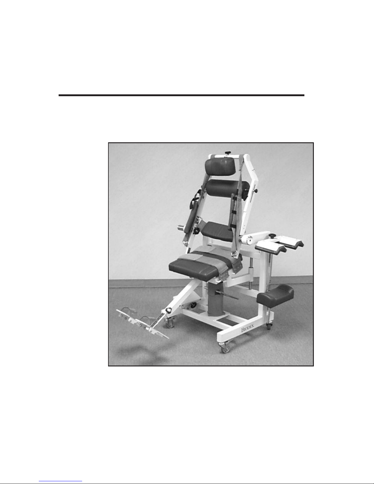
DUAL POSITION BACK EX/FLEX
ATTACHMENT
OPERATION MANUAL
830-450
Page 2

10. HANGER FOR ACCESSORY CART
This manual contains instructions for the following
Biodex product:
#830-450 Dual Position Back Ex/Flex Attachment
Page 3
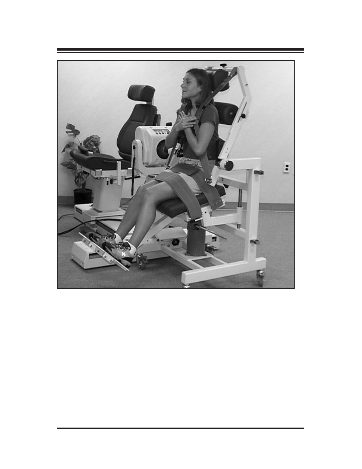
Figure 1: The Biodex Multi-Joint System 3 with Dual Position Back Ex/Flex
Attachment. The patient is exercising in the semi-standing (functional) position. For exercise or testing in the seated-compressed position, remove the lumbar pad, raise the seat to the inclined position, and insert both the sacral pad
and lower extremity compression device.
The Dual Position Back Ex/Flex Attachment was created to provide clinicians with greater versatility in back testing and rehabilitation. With this
system, patients can perform both semi-standing and seated-compressed
lumbar back extension/flexion. This allows the clinician to objectively
measure muscle performance in both functional and isolated capacities.
The attachment is easily connected or disconnected from the dynamometer and conveniently rolled aside for storage when not in use.
INTRODUCTION
— 3— INTRODUCTION
Page 4

The ability to test or exercise in a functional pattern is important because,
in real life activities, musculature other than the abdominals and erector
spinae are used to perform such tasks as lifting. The semi-standing position, in which the seat is slightly reclined from horizontal, allows for hip
involvement and a range of motion comprising both lumbar and sacral
movement. This position simulates an upright standing position with
respect to the musculature that contributes to this posture but reduces
some of the compressive forces acting at the low back. Past history has
demonstrated that this position is comfortable for the patient and results
in greater compliance to the rehabilitation program. Many clinicians consider the semi-standing position effective for functional assessment of
lower back extension/flexion motion. A necessary degree of stabilization
is achieved through the use of a cervical support, thoracic support, chest
harness, scapula pad, pelvic support, thigh strap, and foot cuffs.
Effective lumbar isolation, on the other hand, is achieved by placing the
patient in the "seated compressed" position and using the femurs to
immobilize the pelvis. This fixation is accomplished by positioning the
patient in the seat against a specially designed sacral pad and securing
him/her into this surface with the lower extremity compression pad.
Laterally, the patient is secured by the contour of the pad. Of course, all
the stabilization features noted for the semi-standing position are also
incorporated to ensure maximal stabilization. Range of motion should
be limited to that which is produced from the lumbar area.
When placed in the seated-compressed position with the seat slightly
inclined from horizontal, the patient maintains some degree of lordosis,
resulting in less deformation of the discs and reduced loads on the lumbar region. The sacral pad also helps to maintain this lordotic position
and reduced compression. Because of these factors, isolated lumbar testing is very safe — especially when performed isometrically.
Numerous reasons for isolated lumbar testing have been recognized.
One important factor stems from a research standpoint. As with joint
testing, the more isolated the motion and the better the stabilization, the
more reproducible the task. Because the movement is isolated the clinician may be sure that the abdominals and erector spinae are being exercised to full capacity with minimal contributions of hip, gluteal, and
other lower extremity musculature.
1. PARTS AND COMPONENTS
INTRODUCTION — 4—
Page 5
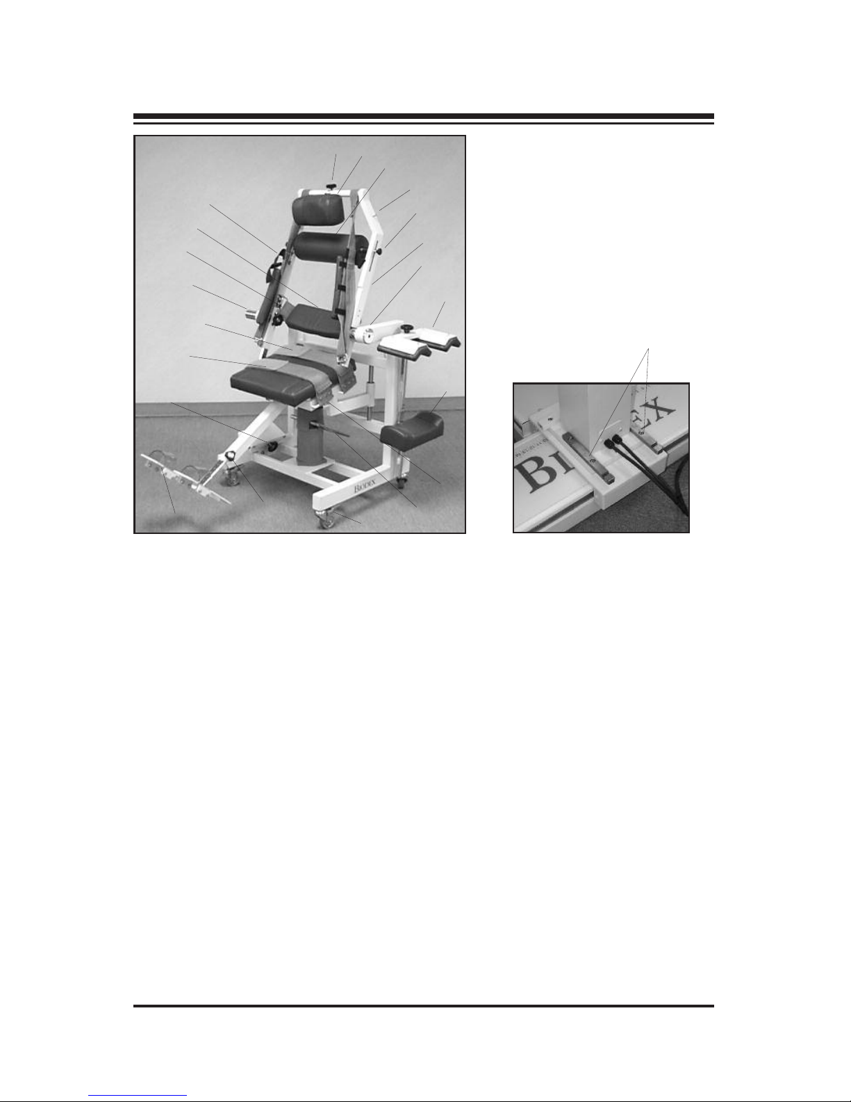
Figure 2: The Biodex Dual Position Back Ex/Flex Attachment major
components and adjustment mechanisms.
1. Headrest Adjust Lock Knob
2. Cervical Headrest
3. Scapula Roll
4. Back Attachment Support Arm
5. Scapula Roll Adjustment Knob
6. Torso Straps with Clavicle Pads
7. Goniometer
8. Lower Extremity Compression Device
9. Sacral Pad
10. Seat Tilt Lever
11. Height Foot Pedal
12. Positive-Lock Casters (all four wheels)
13. Footrest Adjust Lock Knob
14. Footrest
15. Docking Clamp with Lock Knob
16. Femur Strap
17. Pelvic Strap
18. Connecting Hub
19. Connecting Hub Lock Knob
20. Lumbar Pad
21. Torso Strap Buckles
22. Ex/Flex Mounting Bars (inset)
PARTS AND ADJUSTMENTS
— 5— PARTS AND ADJUSTMENTS
1
2
3
4
5
6
7
8
9
10
11
12
13
14
15
16
17
18
19
20
21
22
Page 6
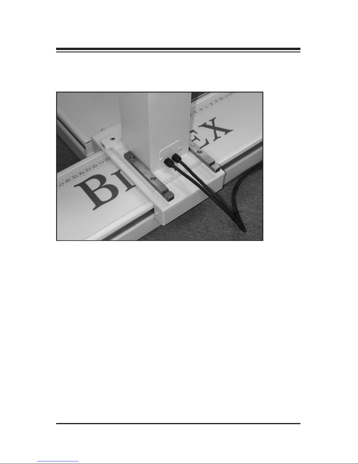
Attaching the Ex/Flex Mounting Bars
(See Figure 3.)
Figure 3. The Ex/Flex Mounting Bars installed on the dynamometer base.
1. Using a 5/16" Allen wrench, remove the three bolts each on the left
and right side of the dynamometer pedestal base that secure the
base to the dynamometer travel. Discard the bolts.
2. Position the ex/flex mounting bars over the dynamometer pedestal
base and install with the two new bolts supplied.
SETUP AND INSTALLATION
SETUP AND INSTALLATIONS — 6—
Page 7

Connecting the Back Attachment to the Biodex System 3
(See Figures 4 - 8.)
Figure 4. The Biodex Dual Position Back Ex/Flex Attachment secured to the
Biodex Multi-Joint System.
1. Position the dynamometer facing out from the chair at the center of
the top of the T-base (0-degrees rotation).
2. Loosen the dynamometer height, tilt and rotation locking knobs.
3. Set the controller to Set-Up mode.
4. Rotate the dynamometer shaft so that the red dot is up.
5. Lift up on the back attachment support arm to align the red dot on
the connecting hub with the red dot on the dynamometer shaft.
6. Push the back attachment connecting hub onto the dynamometer
shaft until it is fully seated, adjust the dynamometer height, tilt and
rotation as required for a proper fit.
7. Fully tighten the back attachment connecting hub lock knob.
8. Secure the docking clamp at the base of the back attachment to the
ex/flex mounting bars at the base of the dynamometer. Push the
bracket down as you tighten the knob. The lip of the bracket will be
drawn into the grooves on the bars. Fully tighten the knob to draw
the back attachment against the bars.
3. SETUP PROCEDURE
— 7— SETUP AND INSTALLATIONS
Page 8
9. Lock all four casters on the back attachment.
10. Tighten the dynamometer height, tilt and rotation locking knobs.
The system is now ready for use.
3. SETUP PROCEDURE
SETUP AND INSTALLATIONS — 8—
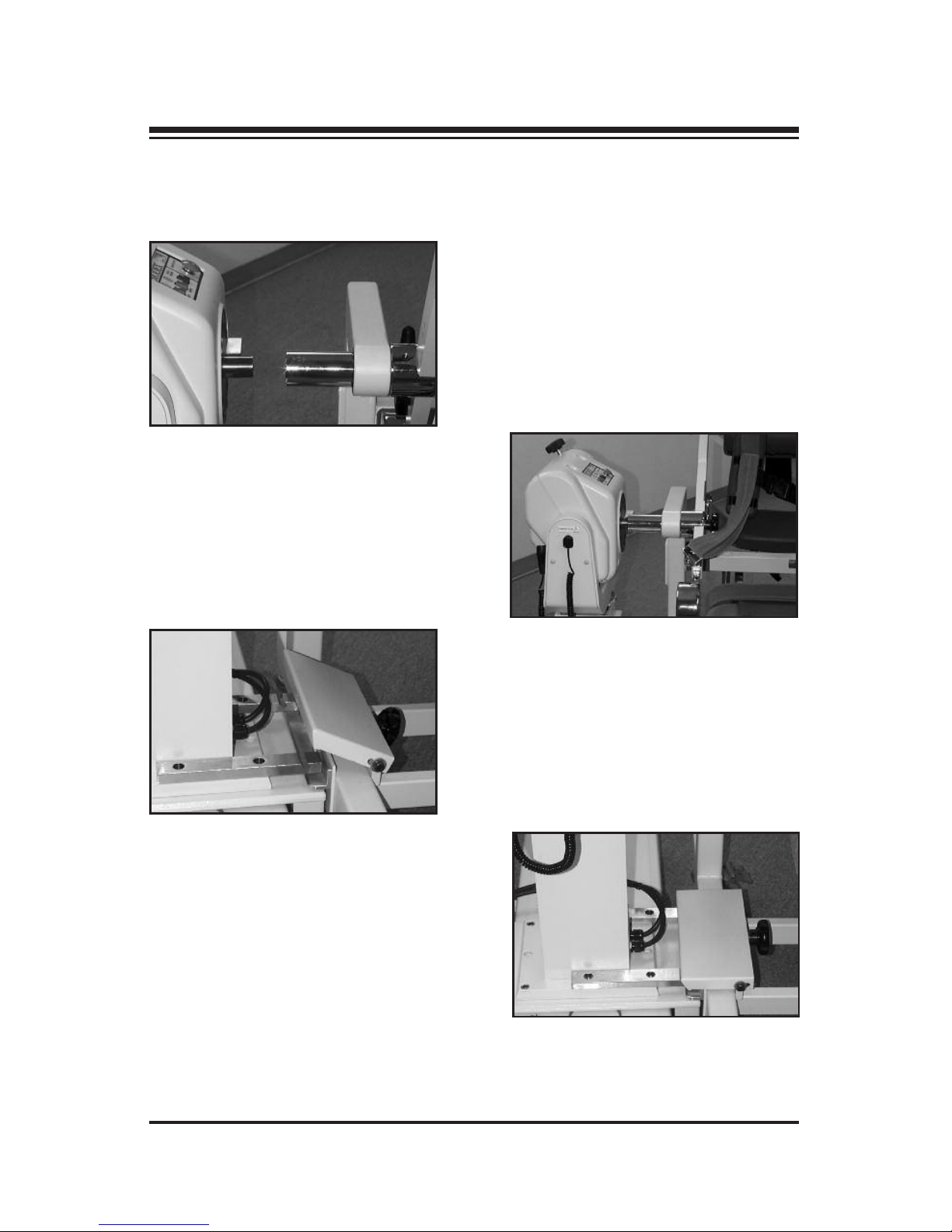
Figure 5. Align the connecting
hub red dot with the dynamometer
shaft red dot.
Figure 6. Tighten the connecting
hub lock knob to draw the back
attachment securely to the
dynamometer.
Figure 7. Secure the docking
clamp at the base of the back
attachment to the bars at the base
of the dynamometer. Push the
bracket down as you tighten the
knob.
Figure 8. The docking clamp fully
secured to the dynamometer base.
Page 9

Releasing The Back Attachment From the Dynamometer
1. Loosen the back attachment docking clamp knob until the bracket
pops out of the grooves in the dynamometer bars.
2. Unlock all four back attachment locking casters.
3. Loosen dynamometer height, tilt and rotation locking knobs.
4. Fully loosen the back attachment hub locking knob and pull the
back attachment off the dynamometer.
4. UPPER EXTREMITY EXERCISE
— 9— SETUP AND INSTALLATIONS
Page 10
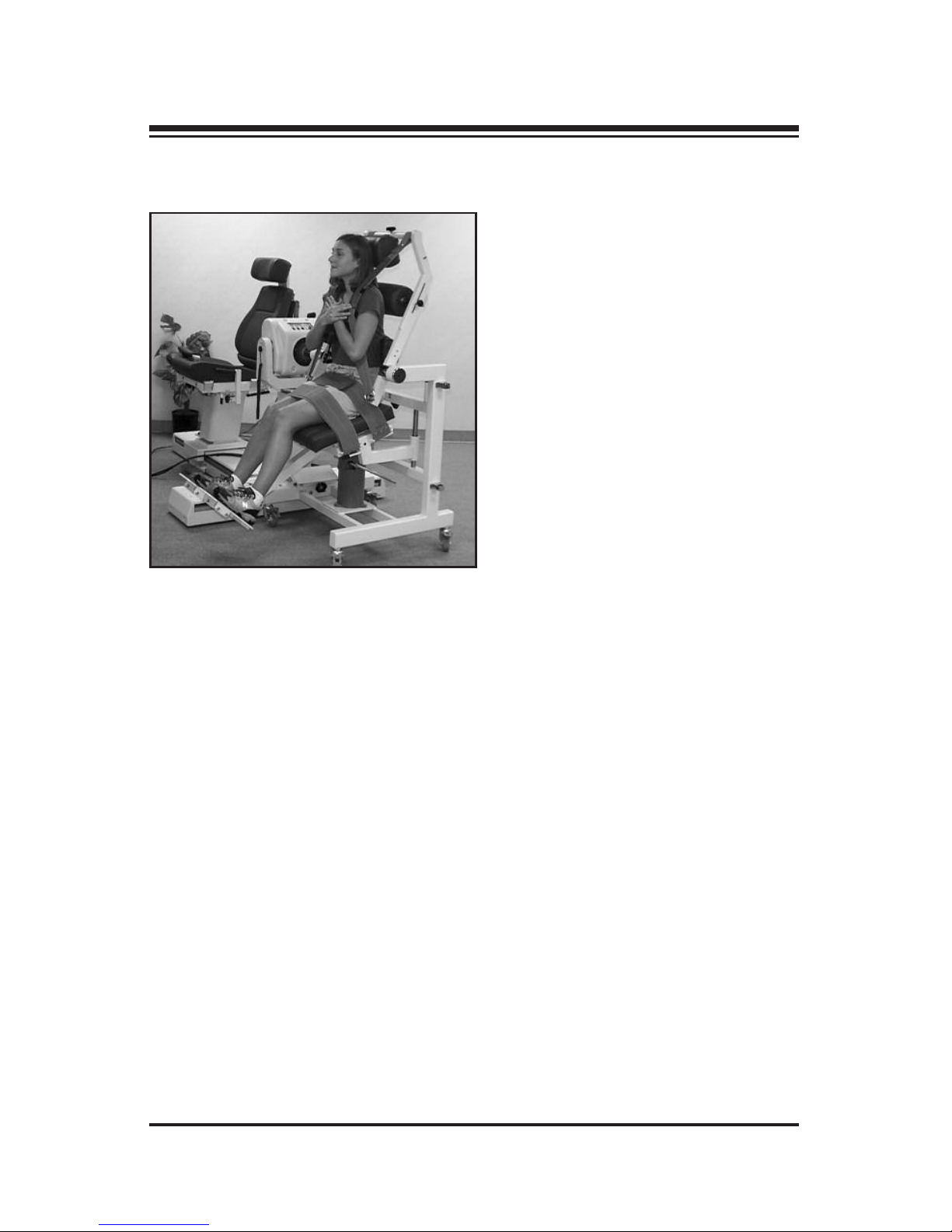
Semi-Standing (Functional Position)
(See Figure 9.)
Figure 9. The Biodex Dual Position Back Ex/Flex
Attachment and Biodex Multi-Joint System with a
patient in the semi-standing (functional) position.
NOTE: It is recommended that patients remove their glasses during testing or
exercise with this attachment.
1. Place controller in Setup mode and press Standby.
2. Holding back attachment support arm firmly with one hand, press
ON, then Start to allow rotation of the dynamometer shaft. Use the
dynamometer Balance Adjustment dial to balance the attachment in
the vertical position. Move the support arm to 50 degrees on attachment goniometer. Press Stop on controller or dynamometer to lock
the support arm in place.
3. Ensure seat is in down position (front of seat tilted down approximately 15°. If not, lift up on seat, flip up seat adjustment lever and
lower seat appropriately.
4. Ensure that lumbar pad is installed and that both the sacral pad and
lower extremity compression device are removed and stored in their
respective holders.
PATIENT POSITIONING & STABILIZATION
PATIENT POSITIONING & STABILIZATION — 10 —
Page 11

5. Seat patient. Move patient anteriorly or posteriorly to approximate
longitudinal spinal axis with the fixed axis of the Back Ex/Flex
Attachment.
6. Position footrest so that femur is nearly parallel to seat. Knee angle
will be approximately 15 degrees. Note the value indicated on the
footrest position scale so that it may be entered under subject setting.
7. Adjust patient axis height by pumping seat up or down using Seat
Height Foot Pedal located at back of chair base. Align the fixed axis of
the machine with the subject’s anterior superior ileac spines (ASIS).
Half-strokes move seat up. Full strokes held down lower seat.
8. Stabilize lower extremity firmly with pelvic and femur straps. With
the lower torso properly stabilized the patient assumes a posterior
pelvic tilt with a slight degree of knee flexion. Maintenance of posterior pelvic tilt throughout the range of motion places the extensor
muscles in an elongated position which, when moving into a flexion
posture, allows exercise of a broader range of extensors.
9. Adjust Lumbar Pad to provide desired firmness or maximum
patient comfort. To do this, tighten or loosen the Lumbar Pad’s
Velcro® strap.
10. Adjust Scapula Roll to rest between the level of the scapular spines
and inferior angles. To do this, press in simultaneously on the
Scapular Pad Adjustment Knobs and slide the pad up or down into
any of the notches provided. Affirm that this is a comfortable position for the patient.
11. If necessary, loosen the Headrest Adjusting Knobs and adjust
Cervical Headrest to below the occipital protuberance, or to patient
comfort.
12. Apply torso straps firmly and adjust clavicle pads on straps for maximum patient restraint and comfort. Secure tethering strap across the
patient’s chest.
5. LOWER EXTREMITY EXERCISE
— 11 — PATIENT POSITIONING & STABILIZATION
Page 12

The torso straps can also be crisscrossed over the chest by sliding
one strap through the slot of the cervical pad on the second strap.
This is generally the most comfortable strap arrangement for most
patients. The torso straps can also be used independently on each
side. In either case, each strap is guided through the D-Ring on the
appropriate side near the base of the back attachment frame and
doubled back to be secured via the Velcro® patches. Slide the shoulder pads up or down the strap to position for patient comfort.
NOTE: Because different body types require different torso strap angles for
maximal patient comfort, the straps may be positioned above or below the
strap peg located where the straps are secured to the back attachment frame.
It is also acceptable to wrap the strap around the frame itself in order to
accommodate large body types.
13. Provide speed to the dynamometer. Manually assist patient through
range of motion while still in Setup mode to determine if axis of
rotation is properly set.
NOTE: Instruct patient to maintain proper posture, or support patient
manually, while in Setup mode or during mode changes. When changing
modes, place patient in flexion with manual assist (if necessary) to reduce
possibility of undesired movement into extension from gravitational effects.
Always secure the support arm when turning mode switch on controller
past Setup mode.
14. Set ROM Limits 1 and 2 in Setup mode. Set Percent Range dials 1
and 2 if required by patient protocol.
15. Proceed to the desired test/exercise mode. Select "Lumbar" as the
joint to be tested and "semi-standing" as the test pattern (refer to
your Advantage Software Operations Manual.) The system is now
ready for patient testing or exercise.
NOTE: Use the Back Ex/Flex goniometer to establish anatomical reference.
Flexion is "towards," extension is "away." Begin the test/exercise with the
patient in the flexed position. The initial movement is extension (away.)
6. APPLICATIONS
PATIENT POSITIONING & STABILIZATION — 12 —
Page 13
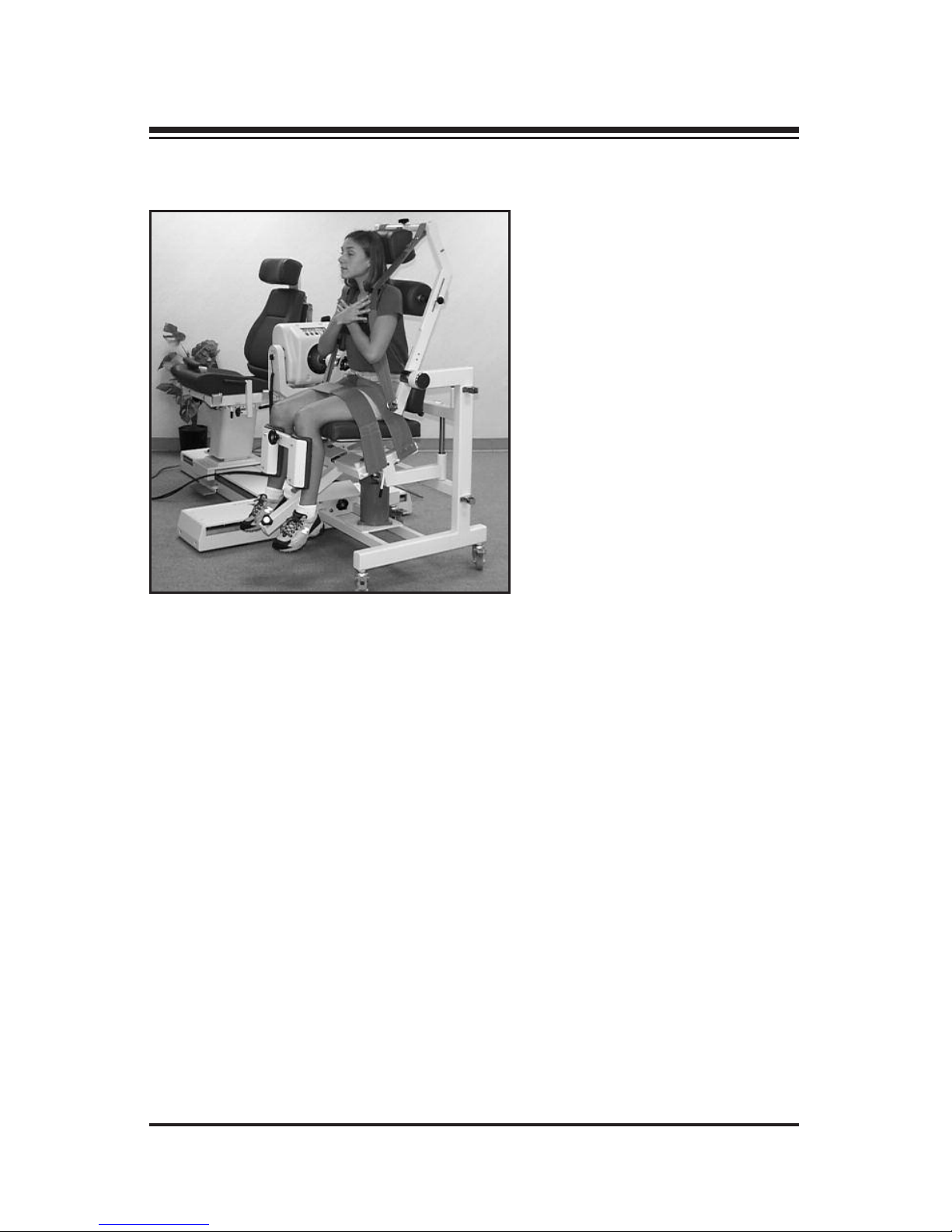
Seated-Compressed (Isolated Lumbar Position)
(See Figure 10.)
Figure 10. The Biodex Dual Position Back
Ex/Flex Attachment and Biodex Multi-Joint
System with the patient in the seatedcompressed (isolated lumbar) position.
NOTE: It is recommended that patients remove their glasses during testing or
exercise with this attachment.
1. Place controller in Setup mode and press Standby.
2. Holding back attachment support arm firmly with one hand, press
ON, then Start to allow rotation of the dynamometer shaft. Use the
dynamometer Balance Adjustment Dial to balance the attachment in
the vertical position. Move the support arm to about 50 degrees on
attachment goniometer. Press Stop on the controller or dynamometer
to lock the support arm in place.
3. Remove Lumbar Pad and insert Sacral Pad, with scale facing up,
into Sacral Pad Receiving Tube.
6. APPLICATIONS
— 13 — PATIENT POSITIONING & STABILIZATION
Page 14

4. Ensure seat is in inclined position (front of seat tilted upward
approximately 15°). If not, lift up on seat until it locks into the proper position.
5. Seat patient. Move patient anteriorly or posteriorly to approximate
longitudinal spinal axis with the fixed axis of the Back Ex/Flex
Attachment.
6. Position footrest so that it will not interfere with patient positioning.
7. Adjust patient axis height by pumping seat up or down using Seat
Height Foot Pedal. Align the fixed axis of the machine with the subject’s anterior superior ileac spines (ASIS’s). Half-strokes move seat
up. Full strokes held down lower seat. Note the value indicated on
the seat height scale so that it may be entered under subject settings.
8. Adjust Sacral Pad to provide desired firmness or maximum patient
comfort. To do this, loosen the Sacral Pad locking knob and slide the
pad to that it is flush against the patient’s sacrum.
9. Insert the Lower Extremity Compression Device into the receiving tube
directly beneath the center of the seat. The Compression Device Locking
Knob should be on bottom with the pads pointing up. Place the patient’s
legs between the anterior and posterior pads and slide the device in
toward the chair until there is firm contact with the femur and the lower
leg is perpendicular to the supporting surface. Tighten the locking knob
for the compression device. Secure pelvic and femur straps.
10. Adjust Scapula Roll to rest between the level of the scapular spines
and inferior angles. To do this, press in simultaneously on the scapular pad adjustment knobs and slide the pad up or down. Affirm that
this is a comfortable position for the patient.
With the lower torso properly stabilized the patient assumes a
posterior pelvic tilt with a slight degree of knee flexion. Maintenance
of posterior pelvic tilt throughout the range of motion places the
extensor muscles in an elongated position which, when moving into
a flexion posture, allows exercise of a broader range of extensors.
11. If necessary, loosen the Headrest Adjustment Knobs and adjust
Cervical Headrest to below the occipital protuberance, or to patient
comfort.
12. Apply torso straps firmly and adjust clavicle pads on straps for maximum patient restraint and comfort. Secure tethering strap across the
patient’s chest.
6. APPLICATIONS
PATIENT POSITIONING & STABILIZATION — 14 —
Page 15

The torso straps can also be crisscrossed over the chest by sliding
one strap through the slot on the cervical pad of the second strap.
This is generally the most comfortable strap arrangement for most
patients. The torso straps can also be used independently on each
side. In either case, each strap is guided through the D-Ring on the
appropriate side near the base of the back attachment frame and
doubled back to be secured via the Velcro® patches. Slide the shoulder pads up or down the strap to position for patient comfort.
NOTE: Because different body types require different torso strap angles for
maximal patient comfort, the straps may be positioned above or below the
strap peg located where the straps are secured to the back attachment frame.
It is also acceptable to wrap the strap around the frame itself in order to
accommodate large body types.
13. Provide speed to the dynamometer and manually assist patient
through range of motion while still in Setup mode to determine if
axis of rotation is properly set.
NOTE: Instruct patient to maintain posture, or support patient manually,
while in Setup mode or during mode changes. When changing modes, place
patient in flexion with manual assist (if necessary) to reduce possibility of
undesired movement into extension from gravitational effects. Always secure
the support arm when turning mode switch on controller past Setup mode.
14. Set ROM Limits 1 and 2 in Setup mode. Set Percent Range dials 1
and 2 if required by patient protocol.
15. Proceed to the desired test/exercise mode. Select "Back Velocity
Spectrum" from the Advantage Software "Operations/Test" menu
(refer to Advantage Software Operations Manual.) The system is
now ready for patient testing or exercise.
NOTE: Use the Back Ex/Flex goniometer to establish anatomical reference.
Flexion is "towards," extension is "away." Begin the test/exercise with the
patient in the flexed position. The initial movement is extension (away.)
6. APPLICATIONS
— 15 — PATIENT POSITIONING & STABILIZATION
Page 16

PASSIVE MODE
1. The passive mode may be used to assist patients through a range
that they cannot actively move through, thereby helping to
increase range of motion.
2. Non-reciprocal contraction types (Concentric/Eccentric,
Eccentric/Concentric) or eccentric contractions types may be
performed in a passive mode. Although research on eccentrics
involving the back is scarce, the functional importance is well
known. Submaximal eccentrics are commonly performed during
activities of daily living.
3. Placing the patient in the Passive mode may help overcome the
apprehension some patients experience when using isokinetic
equipment. Patients may feel more comfortable knowing that they
do not have to move the equipment, but that the equipment will
assist them.
4. Using the Percent Range dials, a patient may be worked through a
limited portion of the range of motion to limit apprehension or
work in an area where a deficit has been detected.
5. In patients who are experiencing pain and/or weakness at specific
positions, the passive motion can aid them through these points
while they are able to relax the involved muscles.
ISOKINETIC MODE
1. Loading is concentric/concentric.
2. Recommended for:
• Healthy athletes
• End-stage rehabilitation
• Pre-employment screening
• High-speed testing
3. Not recommended for acute mechanical pain. Patients with acute
inflammation may first be rehabilitated in the passive or isometric
mode.
CLINICAL APPLICATIONS
CLINICAL APPLICATIONS — 16 —
Page 17

ECCENTRIC MODE
1. Eccentrics emphasize the elastic nature of muscle and therefore a
patient can work eccentrically at a greater physiological efficiency.
This translates to greater patient compliance in many cases since
the exercises are subjectively not as hard to perform.
2. There is evidence that eccentric contractions can result in similar
strength gains as concentric contractions. In early stages of rehab
this may be attractive to the clinician and patient.
3. Mark Rowinski, PhD, PT, (Biodex Clinical Protocol Manual, 1988)
states:
"The therapist must focus on the motor control mechanism, and since
bending is assisted by gravity, the eccentric activity of the trunk
extensors should be the prime focus early in the rehabilitation process.
Therapy should progress slowly from eccentrics of the trunk extensors
to concentrics of the flexors and, finally, to concentrics of the trunk
extensors.
This progression makes sense in relation to the sensitivity of the structures involved and the capabilities of the muscles, since the extensors
are about two to three times stronger than the trunk flexors."
ISOMETRIC MODE
1. Since no movement is involved, patients can safely exercise muscle
flexors or extensors at specific angles while placing only minimal
stress on the trunk and back.
2. In the acute stages of rehab, submaximal exercise can be utilized to
maintain or increase strength at specific ranges in the ROM.
8. MAINTENANCE
— 17 — CLINICAL APPLICATIONS
Page 18

BIODEX
Biodex Medical Systems, Inc.
20 Ramsay Road, Shirley, New York, 11967-4704
Tel: 800-224-6339 (In NY and Int’l. call 631-924-9000),
Fax: 631-924-9241 Email: [email protected], www.biodex.com
Certified Quality Management System
 Loading...