

Page 1
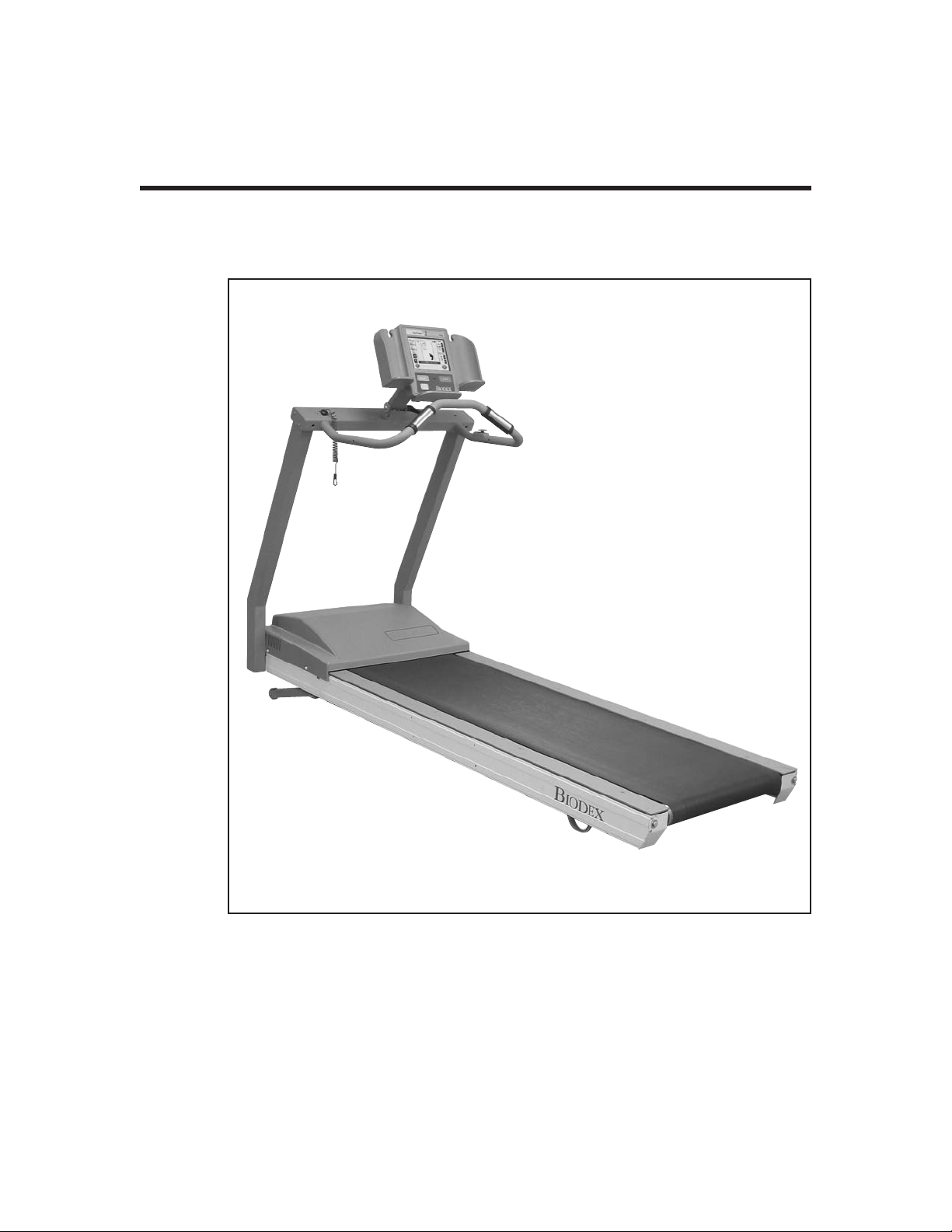
GAIT TRAINER 2
APPLICATION/OPERATION MANUAL
950-385
950-386
950-387
950-395
950-396
950-397
950-398
FN: 05-159 5/05
BIODEX
Biodex Medical Systems, Inc.
20 Ramsay Road, Shirley, New York, 11967-4704, Tel: 800-224-6339 (In NY and Int’l, call 631-924-9000), Fax: 631-924-9338, Email: [email protected], www.biodex.com
Page 2
GAIT TRAINER 2
0413
!
!
This manual covers installation and operation procedures
for the following products:
#950-385 Gait Trainer 2, 115 VAC
#950-386 Gait Trainer 2, 230 VAC
#950-387 Gait Trainer 2, 100 VAC (Japan)
#950-395 Gait Trainer 2, 230 VAC (German)
#950-396 Gait Trainer 2, 230 VAC (Italian)
#950-397 Gait Trainer 2, 230 VAC (French)
#950-398 Gait Trainer 2, 230 VAC (Spanish)
NOTE: All or some of the following symbols, cautions, warnings and notes may apply to your Gait Trainer 2 and
correspond to this operation manual:
Symbol
CAUTION: Federal law restricts this device to sale by or on the order of a medical practitioner. When prescribed for therapeutic purpose, a physician should clearly define the parameters of use (i.e., total work, maxi
mum heart rate, etc.) to reduce the risk of patient injury.
Meaning
Attention, consult accompanying documents.
Symbol signification: Attention, se référer à la notice.
-
— II —
Page 3

TABLE OF CONTENTS
1. INTRODUCTION ..........................................................................................................................1-1
2. CLINICAL CONSIDERATIONS FOR GENERAL USE ..........................................................2-1
3. SETUP ................................................................................................................................................3-1
• Connecting the Printer ................................................................................................................3-1
• Connecting the Safety Lanyard ..................................................................................................3-2
• Handrail Installation (Optional) ................................................................................................3-2
4. GAIT TRAINING MODE..............................................................................................................4-1
• The Gait Training Mode ..............................................................................................................4-1
• Power Up........................................................................................................................................4-1
• The Gait Trainer User Set-up Information Screen....................................................................4-2
• The Audio/Visual Biofeedback Screen......................................................................................4-3
• The Footfalls/Histogram Screen ................................................................................................4-4
5. NORMATIVE DATA ......................................................................................................................5-1
6. GAIT TRAINING OPERATION..................................................................................................6-1
• Gait Trainer 2 Theory of Operation............................................................................................6-1
• Gait Trainer 2 Operation ..............................................................................................................6-1
7. EXERCISE RESULTS ......................................................................................................................7-1
• Exercise Results Parameters ........................................................................................................7-1
• Exercise Results Screen Functions ..............................................................................................7-2
8. TREADMILL OPERATION ..........................................................................................................8-1
• Quick Start Operation ..................................................................................................................8-1
• Quick Start Track/Numeric Display Parameters ....................................................................8-2
• Manual Treadmill Operation ......................................................................................................8-3
• Manual Mode Exercise Track and Numeric Display Parameters ..........................................8-4
9. TREADMILL PROFILES................................................................................................................9-1
• Choosing a Pre-defined Exercise Profile....................................................................................9-1
• Designing a Custon Exercise Profile ..........................................................................................9-3
10. GAIT TRAINER 2 UTILITIES ....................................................................................................10-1
• Configuration ..............................................................................................................................10-1
• Patient Management ..................................................................................................................10-3
• System Maintenance ..................................................................................................................10-5
11. MAINTENANCE ..........................................................................................................................11-1
• Daily Maintenance ......................................................................................................................11-1
• Quarterly Maintenance ..............................................................................................................11-1
Annually or Every 1,000 Hours ................................................................................................1
•
• Maintenance Pr
12. TROUBLE-SHOOTING ................................................................................................................12-1
13. OPTIONAL ......................................................................................................................................13-1
• Installing the Elevation Rockers ..............................................................................................13-1
14. ELECTROMAGNETIC COMPATIBILITY ................................................................................14-1
15. SPECIFICATIONS..........................................................................................................................15-1
ocedures ............................................................................................................11-2
1-1
16. REFERENCES AND BIBLIOGRAPHY ......................................................................................16-1
17. ASSEMBLY DRAWINGS AND SCHEMATICS ......................................................................17-1
— III — CONTENTS
Page 4

1. INTRODUCTION
Designed specifically for rehabilitation and retraining of gait for patients with neurologic and
orthopedic gait dysfunctions, the Biodex Gait Trainer 2 provides both the audio and visual feed-
ack needed to progress patients quickly and safely to normal ambulation.
b
The Gait Trainer 2 is easy to use. The clinician need only select the patient’s age and height for the
treadmill to automatically calculate the exact speed needed to achieve desired step cycle. The
rhythmic movement and the audio feedback provide patients with added stimulus for retraining
of neural pathways to improve gait pattern.
The Gait Trainer 2 promotes correct stride length for early phase patients. By starting out slowly
(with the zero starting speed and small .1 step cycle speed increments) it is possible to manually
position the patient’s lower extremities in the desired patterns for gait, thus reinforcing the proper techniques early in the rehabilitation process. As the patient progresses, correct stride length is
coupled to the correct step cycle. When belt speed is increased, the patient must either take longer
strides or more strides to stay on target. Normative data allows clinicians to compare patient
progress to baseline norms.
Of course, the Gait Trainer 2 can also be used for many other rehabilitation treadmill applications.
In treadmill mode, its unparalleled speed control, durability, incline and decline in both forward
and reverse directions, digital feedback, low profile, and choice of handrail configurations make
it the ideal choice for virtually any patient young or old.
The Biodex Gait Trainer 2 comes with a printer which is easy to install and resides on the printer
stand. Options include -3 to 12% incline/decline (ideal for work with back, posture, lumbar spine
and patella patients,) and a choice of handrails.
— 1-1 — INTRODUCTION
Page 5

!
2. CLINICAL CONSIDERATIONS FOR GENERAL USE
The following clinical considerations should be observed for all patients who exercise on the
Biodex Gait Trainer 2. Additional clinical considerations, specific to gait training, are provided in
he chapter titled: Clinical Applications and References.
t
1. All patients should consult a physician before beginning any rehabilitation program.
2. Instruct patient on proper use and all Gait Trainer 2 safety features before beginning exercise.
3. Always attach the Safety Lanyard to the patient’s clothing or wrist before allowing exercise to begin.
4. Ensure patient has stretched and warmed-up prior to starting exercise.
5. Do not allow any patient to exercise unattended on the Gait Trainer 2. Never leave the Gait Trainer 2
running unattended.
6. Periodically monitor the heart rate of patients exercising on the Gait Trainer 2.
7. Begin all exercise at a slow pace, increasing speed gradually to patient tolerance and progressing toward
exercise goals. Always inform the patient immediately prior to increasing or decreasing speed or elevation.
8. If reversing belt direction, bring the Gait Trainer 2 to a complete stop and inform patient that the belt
will begin moving in the opposite direction.
9. Immediately discontinue exercise if patient feels faint, dizzy or short of breath.
10. Never allow anyone to step onto the Gait Trainer 2 while the treadbelt is in motion. Always stop the
Gait Trainer 2 prior to allowing the patient to step up onto the treadbelt.
11. Instruct patients to use the handrails when first learning to walk on the Gait Trainer 2.
1. Tous les patients doivent voir leur médecin responsable avant d’entreprendre la séance de rééducation.
2. Expliquer au patient la bonne utilisation des systémes de sécurité du tapis avant de démarrer la séance.
3. Connector toujours la sangle de sécurité aux vêtements du patient ou poignet avant que le patient ne
commence à travailler.
4. Vérifier que la patient s’est échauffé et a fait des étirements avant de commencer l’entraînement sur le
tapis.
5. Ne pas laisser le patient seul sur le tapis pendant la séance. Ne jamais laisser le tapis tourner sans
patient et sans surveillance.
6. Surveiller de temps à autre la fréquence cardiaque du patient pendant la séance.
7. Démarrer les protocloes à une vitesse lente et augmenter progressivement la vitesse en fonction de la
tolérance du patient et progres uers les objectifs de la séance. Signaler avant de l’appliquer tonte augmentation ou diminution de vitesse ou d’inclinaison.
8. Avant de changer la direction de déplacement du tapis, arrêter le tapis complétement et expliquer au
patient que le tapis va démarrer dans le sens opposé.
9. Arrêter la séance immédiatement en cas de dyspnée, d’étourdissements ou d’autres signes de malaise.
10.
Ne jamais faire monter personne sur le tapis pendant que le tapis est en marche. Arrêter toujours le
tapis avant que le patient ne s’y positionne.
11. Donner la consigne au patient d’utiliser les barres horizontales lors de sa premiére séance sur le tapis.
— 2-1 — CLINICAL CONSIDERATIONS FOR GENERAL USE
Page 6
3. SET-UP
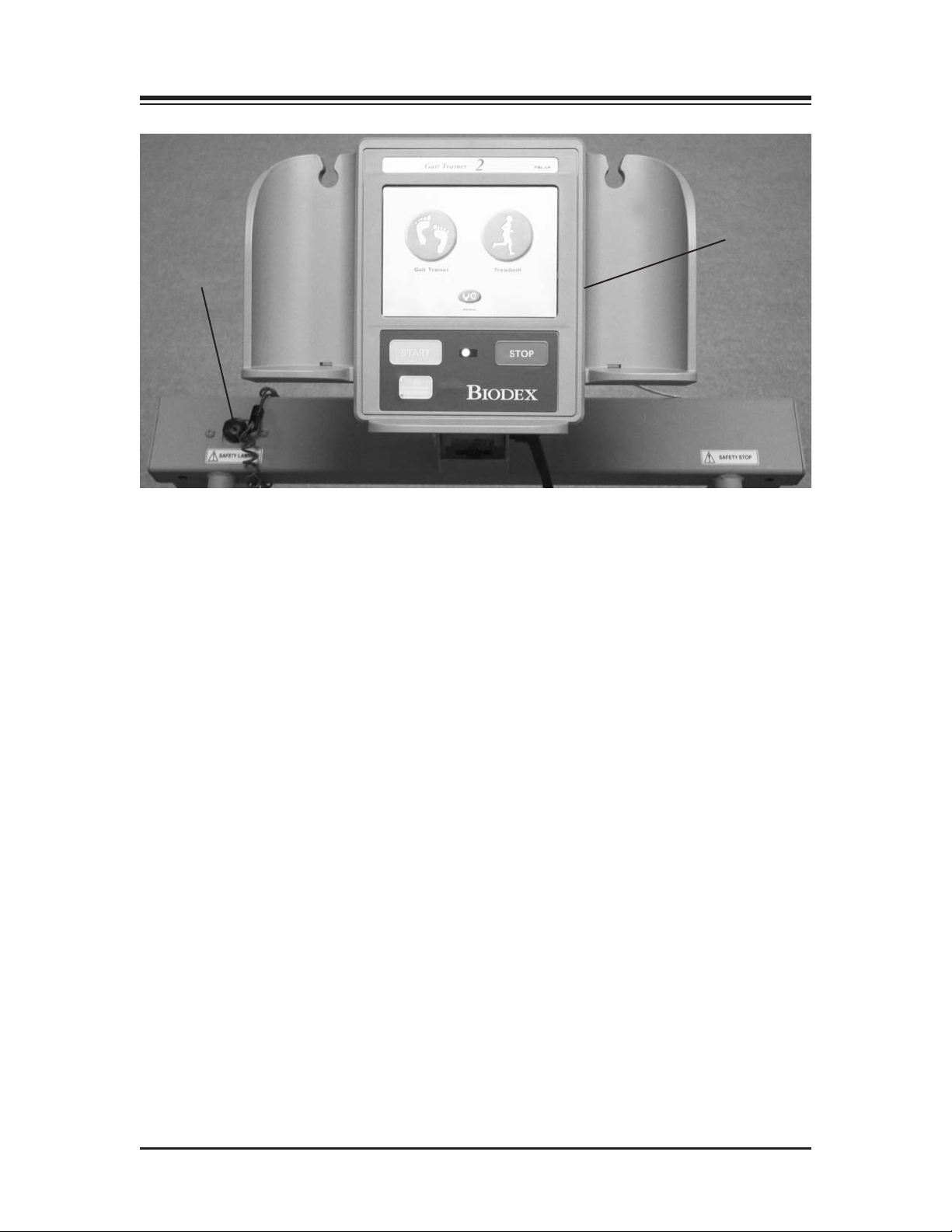
Attach Safety Lanyard
Figure 3.1. Attaching the Safety Lanyard, printer cable and printer.
Attach Printer Cable
(behind display)
Included with the Gait Trainer 2 are a printer, printer stand and Safety Lanyard. These should all
be attached/installed prior to operation of the Gait Trainer 2.
CONNECTING THE PRINTER
(See Figure 3.1.)
The printer cable should be connected to the printer receptacle at the back of the display with the
USB cable end. Attach the opposite end of the cable to the back of the printer. The cord should run
down the back of the display and over the motor cover so as not to be in contact with the moving
belt. Place the printer on the printer stand. Ensure that the printer stand is positioned next to the Gait
Trainer 2 but far enough away so as not to come in contact with the Gait Trainer 2’s moving parts.
Note: The printer receptacle is for the printer only. Do not plug anything else in this receptacle.
Nota: La prose pour imprimante est destinée à la seule imprimante. Ne brancher rien d’autre dans cette prise.
CONNECTING THE SAFETY LANY
(See Figure 3.1.)
A Safety Lanyard is provided. The Gait Trainer 2 will not operate unless the lanyard is attached.
Attach the Safety Lanyar
round end of the Safety Lanyard attaches to the unit via a Velcro® brand hook and loop fastener.
The clip end of the lanyard should be attached to the patient’s clothing or wrist in a way that does
not interfere with the patient’s exercise.
NOTE: Disconnecting the Safety Lanyard (left side of Display/Control Panel) or pressing the red Safety
Stop (atop the right side of the Support Bar) at any time will cause the treadbelt to immediately ramp down
to a full stop and reset to 0.0 mph. The Display will read <Safety Lanyard Removed> and the treadbelt will
not restart until the Safety Lanyard is once again in position and/or <Start> is pressed following use of the
Safety Stop. Display data is not lost in either case. Data accumulation will resume once the lanyard is reconnected and <Start> has been pressed.
d at the left corner of the top cross bar supporting the Display panel. The
ARD
— 3-1 — SET-UP
Page 7
CONTENTS
HANDRAIL INSTALLATION (OPTIONAL)
(See Figures 3.2 – 3.4.)
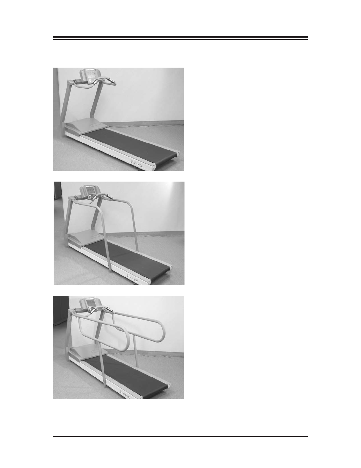
Figure 3.2.
e 3.3.
Figur
Figure 3.4. The Biodex Gait Trainer 2 comes with a sturdy support bar installed (Figure 3.2).
Optional Standard (Figure 3.3) and Geriatric/Pediatric handrails (Figure 3.4) are also available.
SET-UP — 3-2 —
Page 8

CONTENTS
The Biodex Gait Trainer 2 comes with a sturdy support bar, but optional Standard Rehab and
Geriatric/Pediatric handrails are also available. Both optional handrails are installed as follows:
NOTE: Do not fully tighten any screws until all the screws and hardware have been positioned and partially secured.
1. Using a Phillips screwdriver, remove the two screws that attach the cover plate to side of the
display support bar. Set the screws and mounting plates aside.
2. Using a 9/16-inch box wrench, attach the optional handrail to the display support bar with a
3/8-inch lock washer and hex head bolt.
3. Slide the handrail mounting bar into the bottom of the optional handrail so that the screw
holes align.
4. Attach the bottom of the handrail to the platform deck frame using two 1/4 - 20 x 1.75-inch
socket-head screws.
5. Using one 1/4 - 20 x 1.75-inch button-head screw, secure the optional handrail to the support
bar. Pass the screw, threads to the outside of the deck, through the support bar first and into
the optional handrail.
6. Tighten all screws.
7. Using a Phillips screwdriver, replace the cover plate on the display support bar with the two
screws set aside in step #1.
8. Repeat the procedure to attach the opposite optional handrail.
NOTE: Assembly drawings for the procedure, if needed, are provided on pg. 17-2.
— 3-3 — SET-UP
Page 9
4. GAIT TRAINING MODE
The Biodex Gait Trainer 2 can be used for gait training applications, or as a rehabilitation treadmill. The following section describes use in the Gait Training Mode. Rehabilitation treadmill oper-
tion is described later in this manual.
a
THE GAIT TRAINING MODE
The Gait Training Mode is useful for the rehabilitation and retraining of gait for patients with neuralgic and orthopedic gait dysfunctions. It provides both audio and visual feedback for patient
compliance. The rhythmic movement of the treadbelt along with the audio and visual biofeedback, provides the necessary stimulus for retraining neural pathways, thus improving the gait pattern of the patient.
NOTE: It is recommended that the Biodex Unweighing System be used in conjunction with the Gait Trainer
2 to provide a safe environment for the patient and clinician, and also to allow for proper patient positioning for weight distribution and coordination of balance.
POWER-UP
(See Figure 4.1)
To provide power to the Gait Trainer 2, ensure the power plug is connected to an appropriate socket. Press the ON/OFF switch, located on the base of the Gait Trainer 2 in the left corner at the front
end, to the “l” (ON) position. The orange LED on the <On/Standby> key, located at the bottom
left of the display panel, should illuminate to indicate that power to the Gait Trainer 2 is ON. You
can now press the <ON/Standby> key to activate the display panel and bring up the Opening
Menu touch screen.
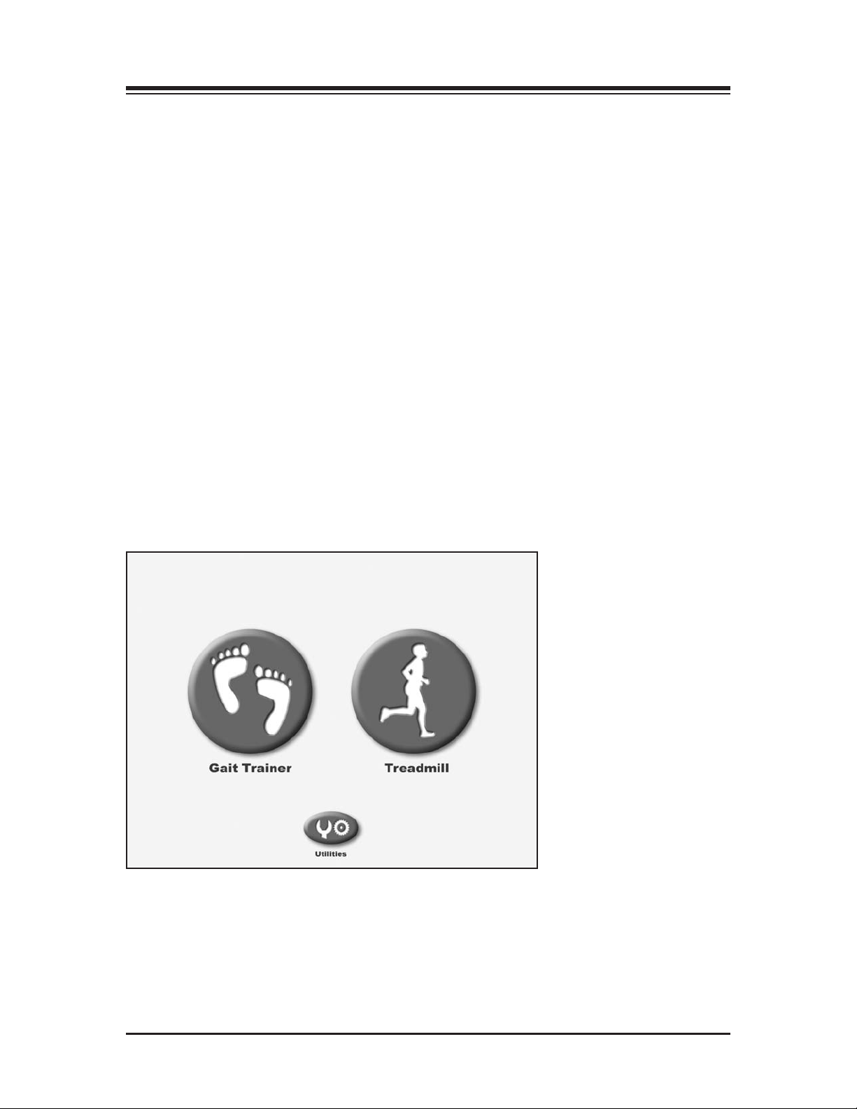
Figure 4.1. The Gait Trainer 2 Opening Menu.
— 4-1 — GAIT TRAINING MODE
Page 10
CONTENTS
THE GAIT TRAINER USER SETUP INFORMATION SCREEN
(See Figure 4.2)
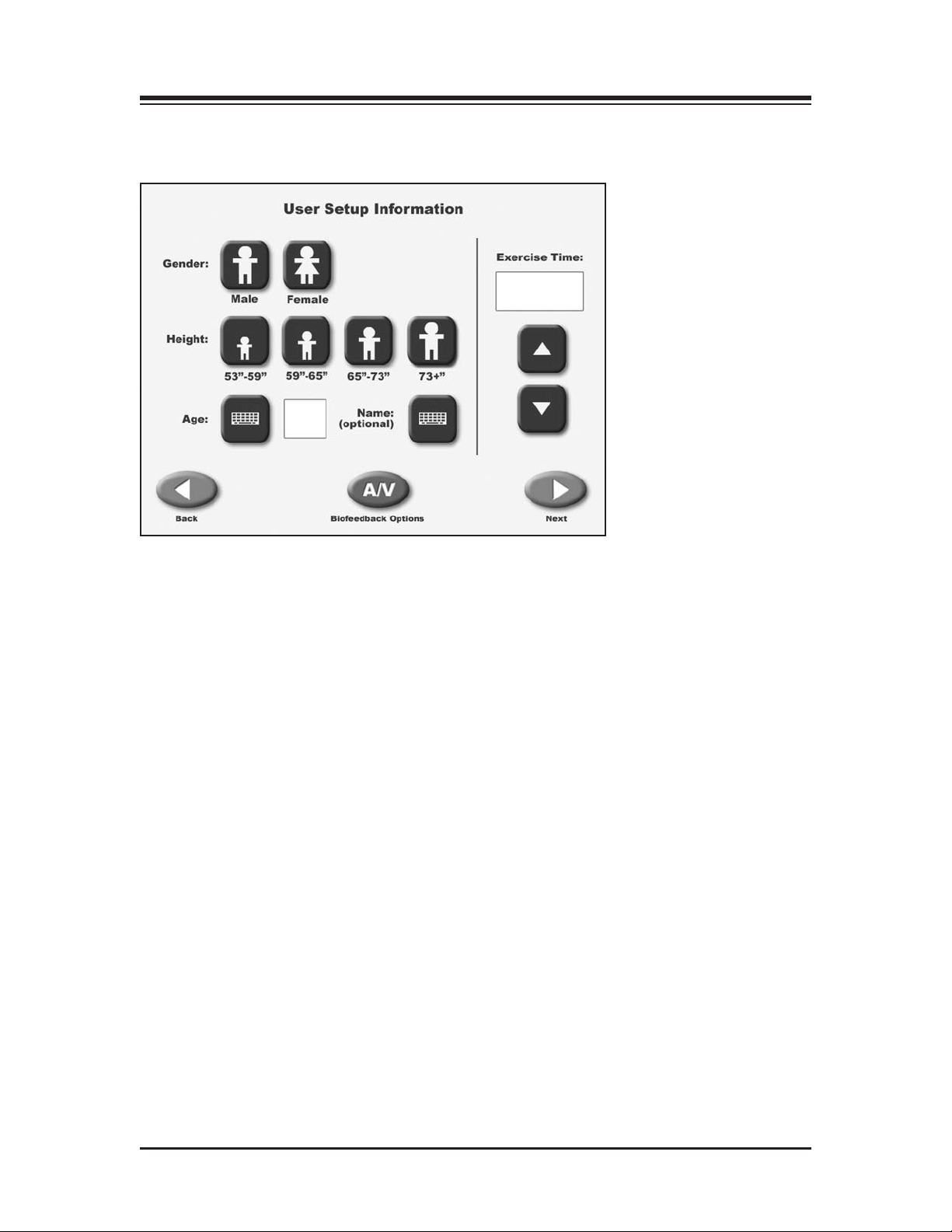
Figure 4.2. The Gait Trainer User Setup Information screen.
The Opening Menu displays three icons: Gait Trainer, Treadmill and Utilities. Touch <Gait
Trainer> to advance to the User Setup Information screen. This screen allows entry of patient
information and parameters used for gait training.
At the User Setup Information screen, simply touch the appropriate icon to begin entering information. A pop-up keypad is used to enter some parameters such as Name and Age. Once the desired
information is entered/selected, touch <Next> to advance to the Footfalls/Historgram screen or
touch <A/V> to advance to the Biofeedback Options Screen. A brief explanation of each parameter
and function on the Gait Training User Setup Information Screen follows.
NOTE: For all screens, <Next> advances to the next screen, <Back> returns the user to the previous screen.
Gait T
raining User Setup Information Screen Parameters
NOTE: The first three parameters, Gender, Height and Age, are mandatory fields and must be completed
befor
e gait training can begin.
• Gender: Touch the appropriate icon to choose <Male> or <Female>.
• Height: This setting is used to determine leg length. Touch the appropriate <Height> icon
to select the desired range.
• Age: Range is from 10 to 80 years old. Touch the <Age> keypad and then use the pop-up
keypad to change the value. Touch <OK> to continue.
• Gait Training Time: Default value is 6:00 minutes. Use the ▲ or ▼ arrows to change the value.
GAIT TRAINING MODE — 4-2 —
Page 11
CONTENTS
• Name: Optional, touch the pop-up <Keypad> to enter the name. Touch <OK> to continue.
A/V Biofeedback Options:Touch <A/V Biofeedback> to enter biofeedback options from
•
the Audio/Visual Biofeedback Options screen.
• <Back>: Go back one screen.
• <Next>: Advance to the next screen.
The AUDIO/VISUAL BIOFEEDBACK SCREEN
(See Figure 4.3.)
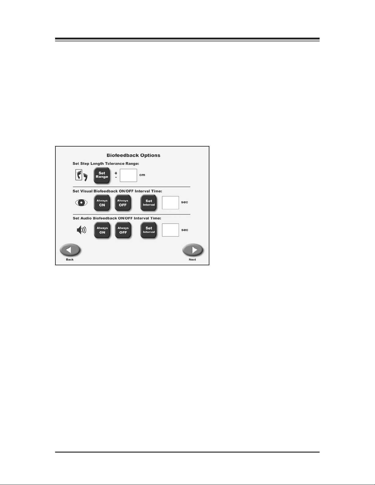
Figure 4.3. The Audio/Visual Biofeedback screen.
The Audio/Visual Biofeedback screen (A/V) is accessed from the Gait Training User Information
screen by touching the <A/V> icon. At this screen, biofeedback parameters can be entered or set.
A brief explanation of each parameter and function follows.
Audio/Visual Biofeedback Screen Parameters and Functions
•
Set Step Length Tolerance Range: Touch <Set Range> and then use the pop-up keypad to change
the value.
•
Set Visual Biofeedback ON/OFF Interval Time:Touch <ON>, <OFF> or <Interval> and enter the
desired feedback time via the pop-up keyboard.
• Set Audio Biofeedback ON/OFF Interval Time: Touch <ON>, <OFF> or <Interval> and enter the
desired feedback time via the pop-up keyboard. The audio tone is not a metronome tempo. The
audio tone is timed to be in sync with when the target box is to appear. Tone is also based on
your last footfall. You can get a tone without a footfall. After a while due to the rhythmic nature
of walking, the tone falls into a seemingly real-time tempo.
Once you have set/entered the desired parameters on the A/V screen, touch <Next> to return to
the Patient Setup Information Screen.
— 4-3 — GAIT TRAINING MODE
Page 12
CONTENTS
THE FOOTFALLS/HISTOGRAM SCREEN
(See Figure 4.4 – 4.5.)
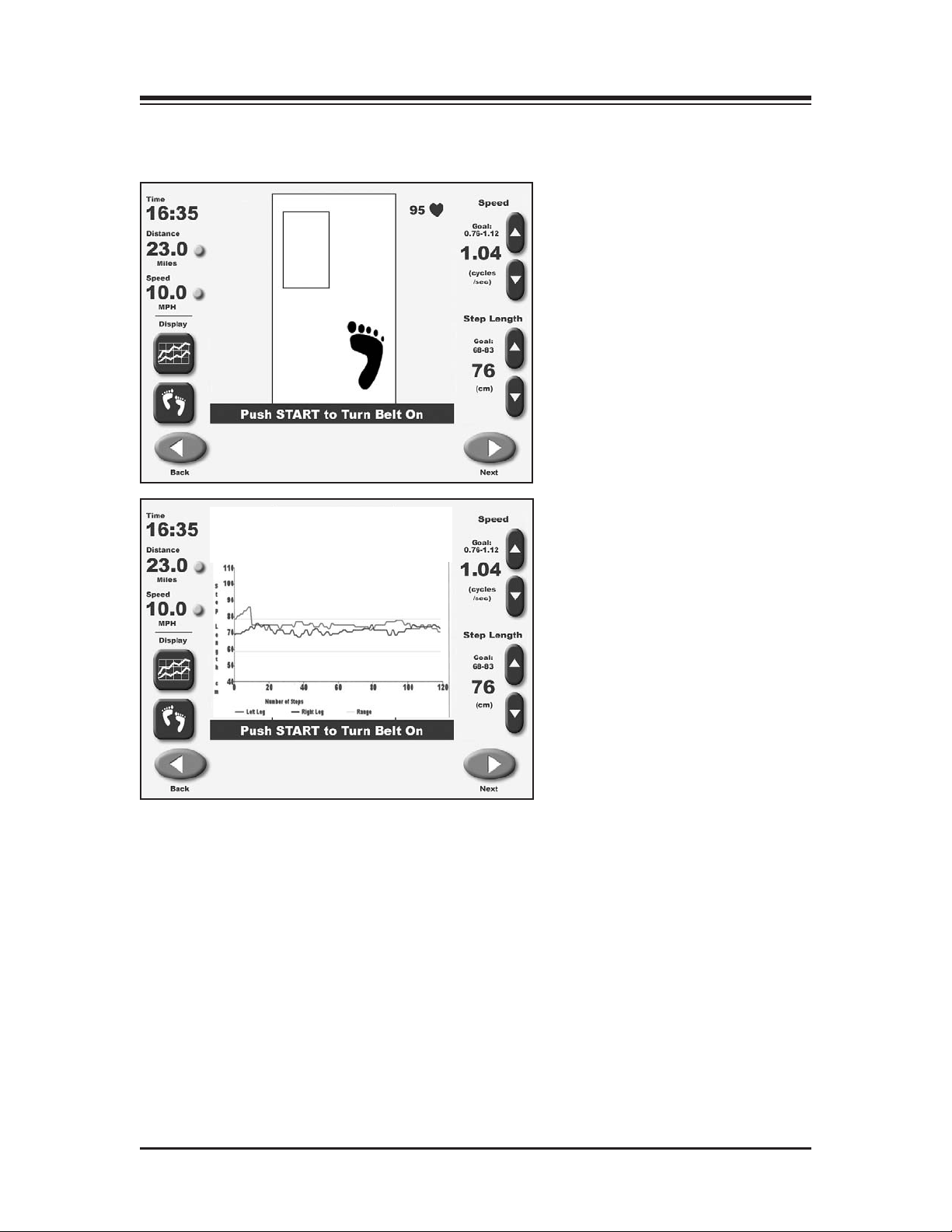
Figures 4.4. and 4.5. Patients can view the Footfalls/Histogram screen with either Footfalls or Histograms
displayed. In the Footfalls scr
for the next foot placement. If a step down does not go in front of the opposite step, the target box will not
appear.
Footfalls/Histogram Screen Parameters
Touch <Next> at the Patient Setup Information screen to advance to the Footfalls/Histogram
screen. At this screen, users can view patient progress via either a footfall or histogram display.
Just touch the appropriate icon at the bottom of the left to toggle between display formats. With
either display, the following parameters can be adjusted at any time as follows:
GAIT TRAINING MODE — 4-4 —
een, the solid foot marks the user's last foot placement while the box is a target
Page 13

CONTENTS
• Speed (Cycles/Second): Located at the top right of the screen. Use the associated ▲ and ▼ icons
to set this goal to match the desired cycles per second.
The step cycle default is 0.10 cycles/sec and the range is 0.1 to 5 cycles/sec. This parameter, in
conjunction with the patient’s height, is used to determine belt speed (since walking speed is
determined by step length and step cycle) and is important for developing proper gait patterns.
Changing either the step cycle or target step length will cause the speed of the belt to increase
or decrease. The initial starting speed of 0.1 cycles/sec can easily be adjusted during the exercise session by using the
NOTE: For visual and audio biofeedback, the treadbelt speed must be greater than 0.8 mph (0.9 kmh, or
0.34 meters/second).
The cycle/sec speed and/or step length regulate the treadbelt speed. If treadbelt speed is below 0.8 mph
(0.9 kmh, or 0.34 meters/second) a message will display noting that the treadbelt is moving too slowly
for biofeedback.
▲ or ▼ arrows.
• Step Length:
right side of the screen to increase or decrease goal value.
• Distance: Located at the top left of the screen, touch <o> to toggle units of measure between
miles, meters and kilometers.
• Speed (Treadbelt Speed): Located at the top left of the screen, touch the solid yellow dot <o>, to
toggle units of measure between KMH, MPH and meters/second.
• Heart Rate: Heart rate monitoring is accomplished by having the subject hold onto both heart
rate handgrips on the front handrail. The heart rate value will be displayed at the top left of the
screen when the handgrips are held.
• Histogram or Footfall: Located at the bottom left of the screen, touch the desired icon to toggle
between these two choices.
Footfalls: Displays alternating right and left targets in the shape of feet. When the patient’s
actual footfalls are detected they are displayed with respect to the target. When the patient falls
within the set standard deviation the footfalls are synchronized with the targets and are told
“good job” by the display. Should they fall outside of the SD the footfalls and targets are out
of synch the display will tell the patient which footfall is outside of the standard deviation by
pr
ompting them to go longer or shorter on the respected foot.
NOTE: Because footfalls are projected based on the subject's last step the screen is always one step
behind. This should not be appar
not go in front of the opposite step, the target box will not appear.
Located at the bottom right of the screen. Use the associated ▲ and ▼ icons on the
ent once the subject falls into a rythmic walking pattern. If a step does
Histogram: Displays footfalls as a 2-pixel wide dot. The X-axis shows distance traveled in
meters and the Y-axis shows the deviation, where 1 pixel is equal to 1cm of deviation. If the
patient goes beyond the SD, the histogram will deviate from straight path.
NOTE: On the histogram graph, the upper and lower lines are the target step lengths plus/minus the
standard deviation. You will notice that the upper line and lower line are equal to the range of the average step length.
— 4-5 — GAIT TRAINING MODE
Page 14
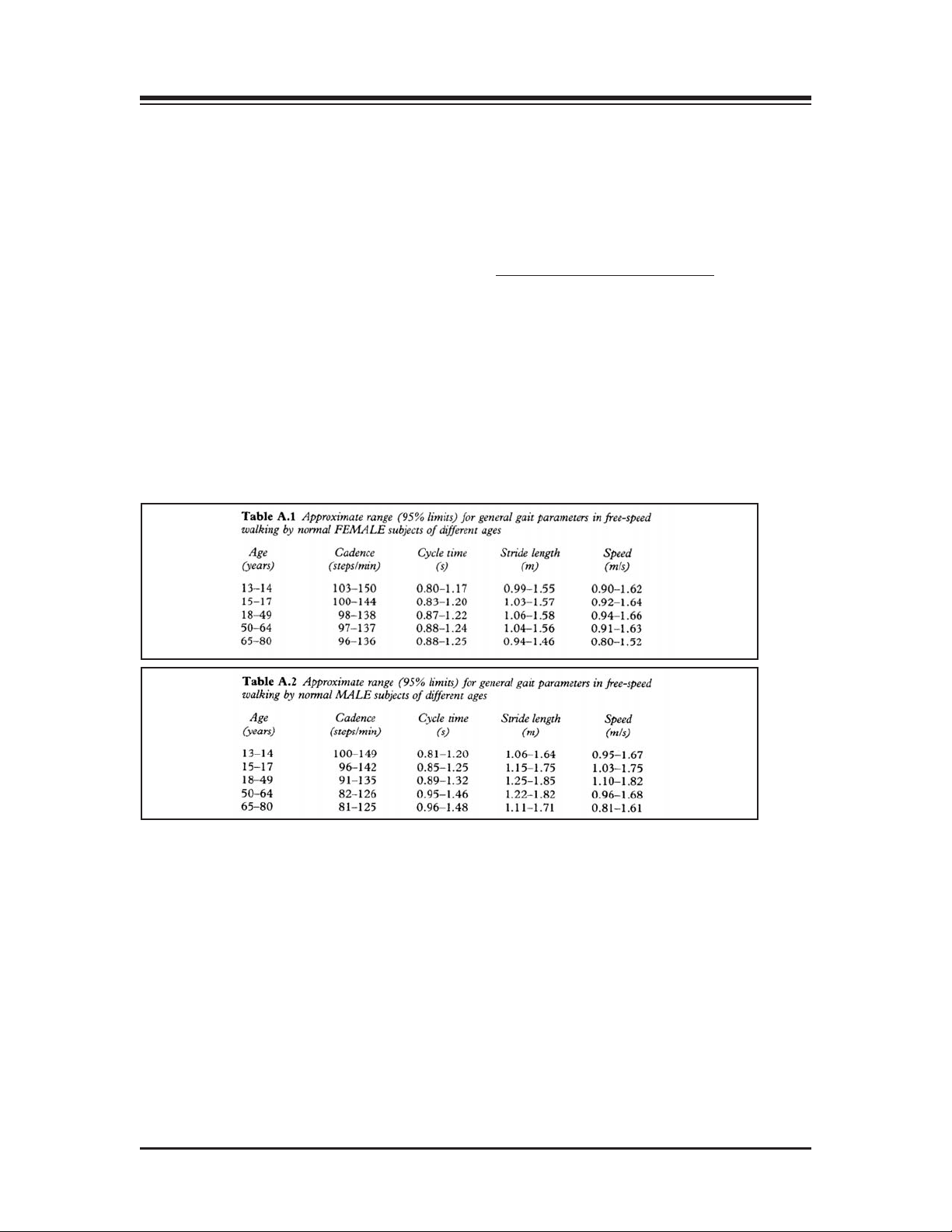
5. NORMATIVE DATA
(Refer to Tables A1 and A2.)
he normative data charts provided in this manual can be used to develop rehabilitation pro-
T
grams and discharge criteria for your patients. The normative values are based on age and gender so comparisons can be easily made.
NOTE: Clarification of Normative Data for the Gait Trainer 2: The normative data presented in the Biodex
Gait Trainer 2 id derived from the reference tables in
Michael W. Whittle, 1997, pgs. 218-219.
Cycle time in Whittle is seconds, whereas the Gait Trainer uses cycles/second. Therefore, data is presented
as the inverse function of the cycle time:
Gait Analysis, An Introduction, 2nd. Edition,
Cycles per second = Cycles
Whittle also presents normative data for stride length. The Gait Trainer 2 uses step length. A stride equals
two steps, therefore, these tables represent stride length divided by two.
-1
— 5-1 — NORMATIVE DATA
Page 15

6. GAIT TRAINER OPERATION
GAIT TRAINER 2 THEORY OF OPERATION
1. Walking (gait) speed can be increased two ways: Increase step frequency (step cycle) or
increase step length.
2. Step cycle: A successive heel strike for the same foot, i.e. Right step, left step, right step. Can
be used to set belt speed based on how many complete successive heel strikes occur within a
econd. .1 cycle per second is very slow, 3 cycles per second is fast. Normal walking step cycle
s
approximates 1 cycle per second.
3. Step Target: A theoretical footfall area based on calculated step length. When step target distance is increased, belt moves faster as steps need to become longer. If target distance is
decreased, belt speed decreases, as steps need to become shorter.
4. Step Length : Is a range [Leg length (cm) x .69] to [Leg length (cm) x .86]. Step Target is placed
within this range plus or minus the entered standard deviation.
5. In Footfall display: Standard deviation is used to prompt walker if they need to go faster on
either right or left side, or both sides. If footfalls occur within standard deviation they are told
good job.
6. In Histogram display: Standard deviation is bandwidth of where step footfalls should occur.
Normal healthy walking at a comfortable pace exhibits step lengths within 3 cm.
GAIT TRAINER 2 OPERATION
At this point, you should be ready to begin gait training using the following procedure:
1. Press the ON/OFF switch, located on the base of the Gait Trainer 2 in the left corner at the
front end, to the “l” (ON) position. The orange LED on the <ON/STANDBY> key, located at
the bottom left of the display panel, should illuminate to indicate that power to the Gait
Trainer 2 is ON.
2. Press the <ON/STANDBY> key to activate the display panel and bring up the Opening Menu
touch screen. Touch <Gait Trainer> to advance to the User Set-Up Information screen.
3. Enter/select the required values on the User Set-Up Information screen. Touch <A/V> to
advance to the Audio/Visual Biofeedback screen.
4. Enter/select the desired values on the Audio/Visual Biofeedback screen. Touch <Next> to
advance to the Footfalls/Histogram screen.
5. Push <Start> to activate the treadbelt. The treadbelt will ramp up slowly to 0.3 mph.
6. Adjust the cycles per second <Speed> setting to a comfortable pace for the user. Once the user
is comfortable, touch <Begin Gait Training> to begin the gait training session and record data.
NOTE: Treadbelt speed must be greater than .8 mph for biofeedback.
uct the subject to follow the prompts on the screen while attempting to place each foot in
Instr
7.
the target area displayed. The system will prompt for each foot (or both feet) to “go longer,”
“go shorter,” or to continue on pace with “good job.”
NOTE: For histogram display
get range is bracketed by two yellow horizontal lines acr
tar
icon to enlarge the histogram viewing area at any time.
8. To pause the gait training session at any time, press <Pause>. The treadbelt speed will decelerate slowly until stopping. To resume, touch <Resume> and then press the <▲> Speed icon
to bring the speed back up to the desired level. Touch <Resume Gait Training> to begin gathering data again.
9. When the gait training session is finished, touch <End>. The treadbelt will slow gradually
until it stops.
ouch <Results> to display exer
T
10.
(all data will be lost).
, the red line denotes the left leg, the blue line denotes the right leg. The
oss the graph. T
cise results or touch <Re-Start> to repeat the training session
ouch the magnifying glass
— 6-1 — GAIT TRAINER OPERATION
Page 16
7. EXERCISE RESULTS
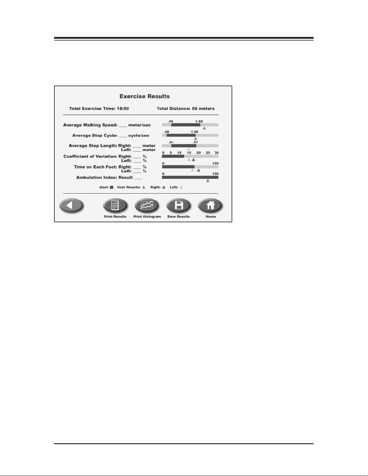
(See Figures 7.1, 7.2 and 7.3.)
xercise results can be reviewed from the Exercise Results screen only after touching <End> to
E
end the exercise session and then touching <Results>.
Figure 7.1. The Exercise Results screen. Note the Exercise Results functions available at the bottom of the
screen.
EXERCISE RESULTS PARAMETERS
Total Exercise Time: This displays the total elapsed time from the start of the exercise until either
the end of the exercise bout or when the <STOP> button is pushed.
Total Distance: This is the total distance traveled by the belt, which is in essence the distance traveled by the patient.
Average Walking Speed: Normative values have been established and are dependent on age and sex.
The norms ar
Average Step Cycle: This is calculated by taking an average for the step cycles during the exercise
bout.
Step Length Target = (leg length *0.69 + (leg length *0.86)/2
Average Step Length: This number is calculated by taking an average for all of the step lengths .
Coefficient of Variance: This is calculated as the amount of variation occurring between footfalls.
e expressed next to the real time value.
— 7-1 — EXERCISE RESULTS
Page 17

CONTENTS
RT/LT time distribution: This is the actual time spent on the mentioned limb. The time spent on each
limb should be equally distributed between right and left. Should they be different, the patient is
pending more time on one leg than the other.
s
Ambulation Index: This is a composite score relative to 100 based on foot-to-foot time distribution
ratio and average step cycle. The goal is 100.
EXERCISE RESULTS SCREEN FUNCTIONS
From the Exercise Results screen the user can perform the following functions:
Back: Return to the Footfalls/Histogram screen by touching < >. All current exercise data will be
lost if you touch <OK> to proceed. To cancel and return to the Exercise Results screen, touch
<Cancel>.
Print Results: Touch the <Print Results> icon to print out a Biodex Gait Training Exercise Summary.
Print Histogram: Touch <Histogram> to print a histogram for this exercise session.
Save Results: This option allows the user to save exercise results for later reporting or export as fol-
lows:
▼
1. At the Save Exercise Results screen, touch the <Save Results> icon to save the results of the
latest gait training session.
NOTE: If no patient name has been entered, you will be prompted that the “Patient Name Must Be
Defined To Save.” Touch <OK> and enter the patient name via the pop-up keyboard. Touch <OK>
again to save the exercise results.
If the user tries to continue without entering a patient name, a prompt will appear advising that all
exercise results data will be lost. Press <OK> to return to the Patient Information Set-Up screen, or
<Cancel> to return to the Patient Name is Undefined screen.
If the patient name has already been entered, touch <OK> on the Exercise Results screen to
2.
save the results for later reporting or export.
EXERCISE RESULTS — 7-2 —
Page 18
CONTENTS
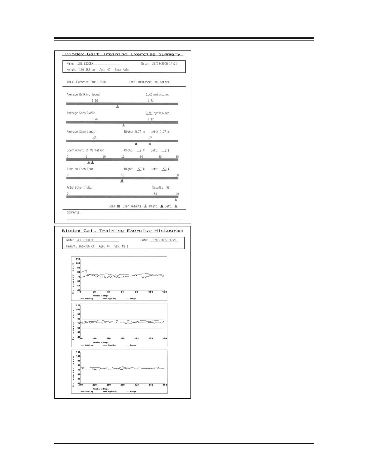
Figures 7.2 and 7.3: Gait Trainer 2 printouts include a Biodex Gait Training Exercise Summary and Biodex
Gait Training Exercise Histogram.
— 7-3 — EXERCISE RESULTS
Page 19
8. TREADMILL OPERATION
(See Figure 8.1.)
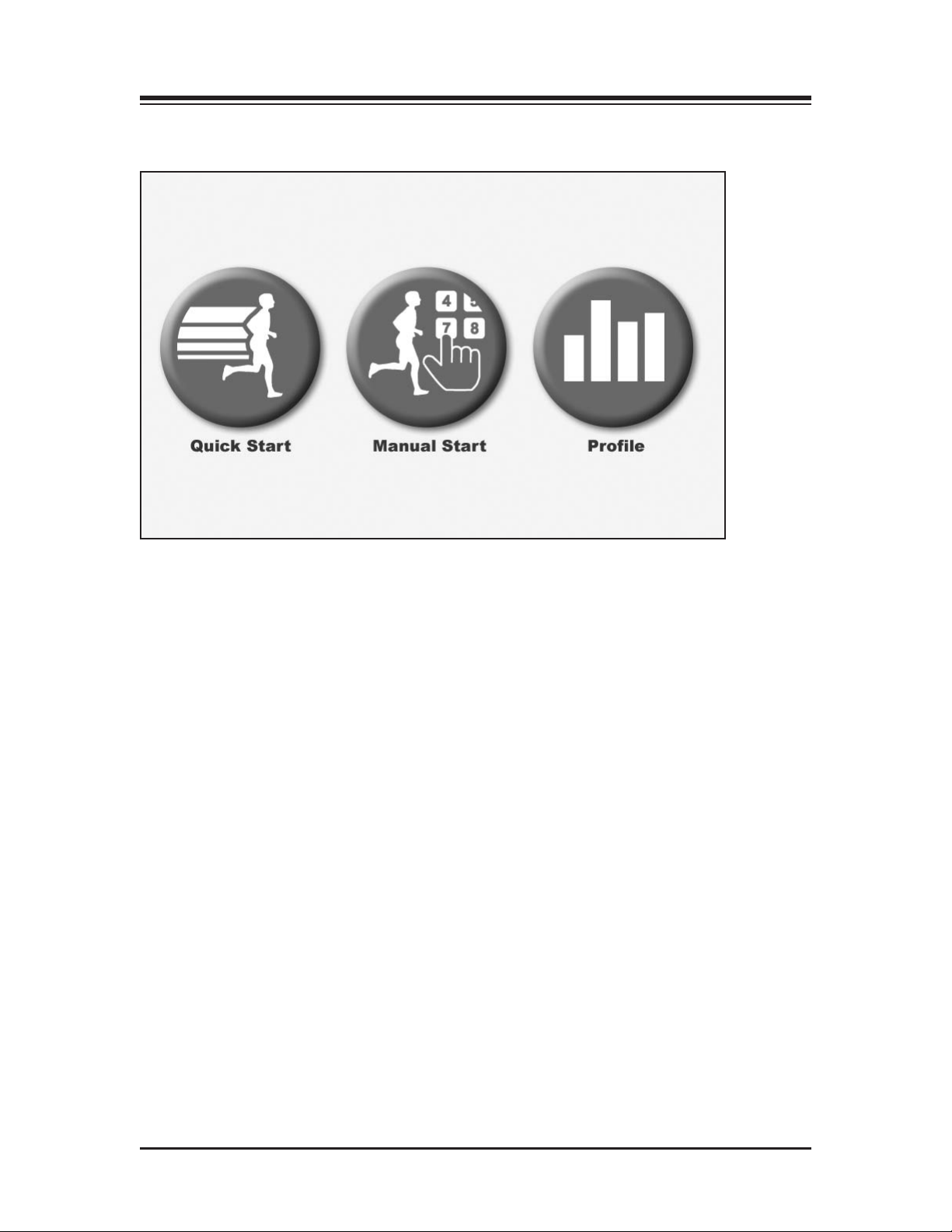
Figure 8.1. The Quick Start feature allows the user to begin the exercise session with minimal input.
QUICK START OPERATION
Although the Gait Trainer 2 offers advanced programming capability, it also features a "Quick
Start" function that allows the user to immediately begin exercise on the system with 1/4-mile
scaled track views.
Quick-Start operation is simple. With the system turned ON, position the user on the treadbelt and
proceed as follows:
1. Press the On/Standby button on the display. The Opening Menu should now be displayed.
2. Touch <Treadmill> on the Opening Menu. The Treadmill Opening Menu should now be
displayed.
3.
Press <Start> on the display to activate the treadbelt. The treadbelt will ramp up to .01 mph.
4. Touch the <
5. Touch the display icons at the bottom left of the screen to toggle between the Quick Start
Exercise Track display and a Numeric display.
6. Touch <Pause> to pause the exercise session at any time. Touch <Resume> to resume the
exercise session.
▲> and <▼> arrows on the screen to adjust <Speed> and <Elevation> as desired.
7. Touch <End> to end the exercise session at any time.
8. Touch <Reset> to return to the Opening screen.
— 8-1 — TREADMILL OPERATION
Page 20

CONTENTS
QUICK START TRACK / NUMERIC DISPLAY PARAMETERS
sers can choose from a Quick Start Exercise Track or Numeric display during Quick Start exer-
U
cise sessions. The following parameters are displayed for both choices.
NOTE: To toggle between displayed parameters (i.e., to change measurement units for calories, pace or distance) touch the yellow dot next to each parameter heading.
Cumulative time in minutes/seconds from the point at which the treadbelt begins to move
Time:
in either direction.
Distance: The distance covered in miles or KM from the beginning to the end of the current exercise session.
Calories: Toggle between:
• Calories: Total calories burned by the user during the current exercise session. This value is dis-
played in real-time.
• Calories/Hr: Total calories that will be burned in one hour if exercise continues at the current
rate. This parameter is dependent upon a default weight of 150 pounds.
• METs: This value reflects the resting rate of Oxygen consumption with one MET equal to the
Oxygen consumption of a seated individual at rest. Thus, a seated individual in a resting state is
consuming one MET. A seated individual exercising at a rate of two METs is consuming twice the
Oxygen of a seated, resting individual. A person exercising at 10 METs is consuming ten times the
Oxygen of a seated, resting individual. To compute the METs of a person actively exercising on
the Gait Trainer 2, the system uses standard calculations based on American College of Sports
Medicine Guidelines for Testing and Exercise. The METs value is always displayed in real/time
for current speed.
Pace: The amount of time it will take the user to move one mile or KM at the current treadbelt
speed.
Heart Rate: This is the real-time heart rate of the user during the exercise session measured using
the contact handgrips.
TREADMILL OPERATION — 8-2 —
Page 21
5. MANUAL OPERATION
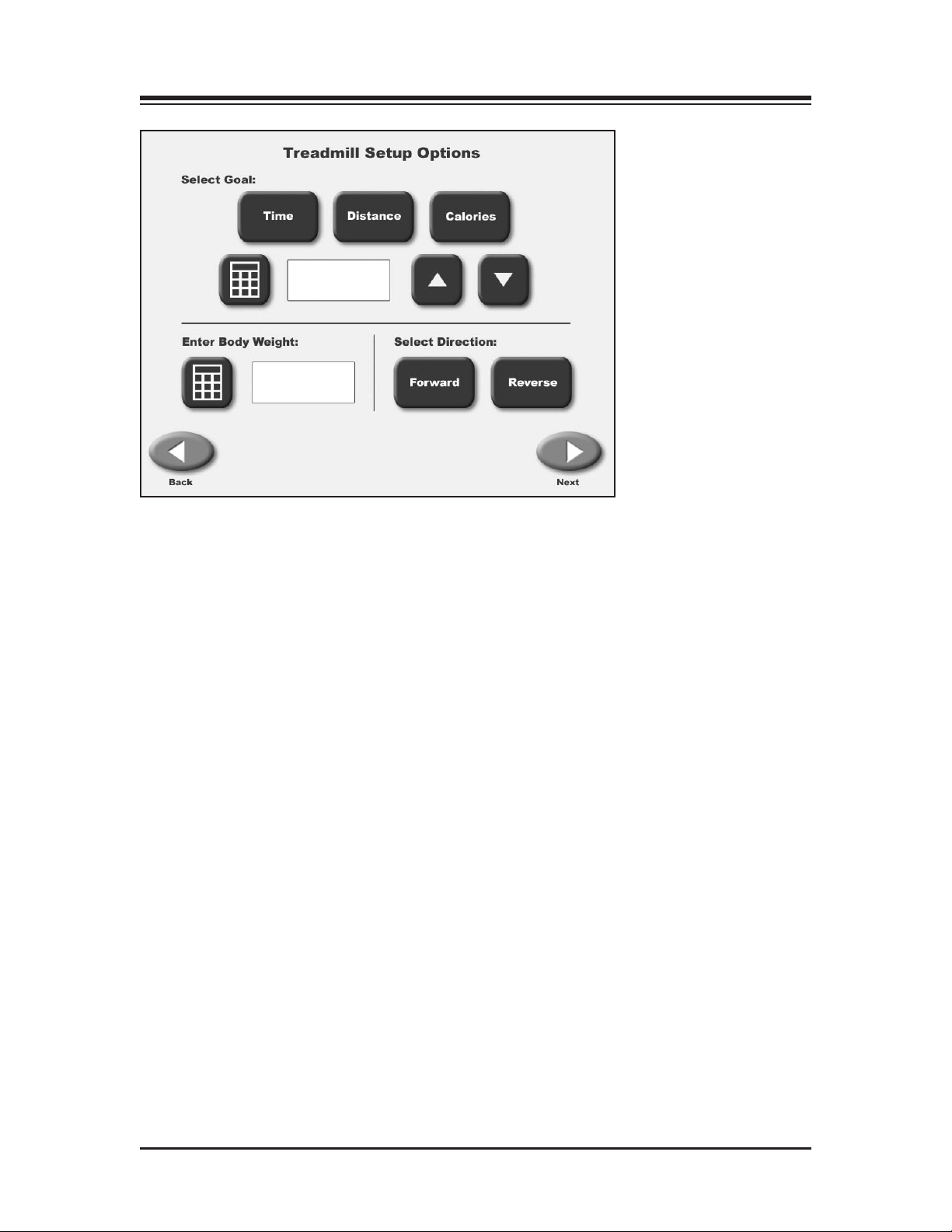
Figure 8.2. The RTM 600 Setup Options screen allows entry of patient-specific information and parameters.
MANUAL TREADMILL OPERATION
(See Figure 8.2.)
Manual treadmill operation is easy. Like the Quick Start function, Manual Start allows the user to
begin exercising quickly. Rather than use default settings, however, this mode of operation
prompts the clinician to enter the patient’s body weight, select the treadbelt direction, and enter
values for Time, Distance and Calories. During the exercise, the user can choose between Exercise
Track or Numeric displays.
Manual Operation Procedure
NOTE: For all screens, <Next> advances to the next screen, <Back> returns the user to the previous screen.
1. At the treadmill Opening Menu select <Manual Start>. The Setup Options screen should now
be displayed.
2. At the Setup Options screen, touch the appropriate icons to enter information and select treadbelt direction. In addition to the <
values for Distance, Calories and Body W
entered/selected, touch <Next> to advance to the Exercise Track display.
3. At this point, you can touch the Display icons at the lower left of the screen to toggle between
the Exercise Track display and a Numeric display.
4. With the Exercise Track or Numeric Display on the screen, simply touch the yellow dot next
to any heading or icon if you want to change the value. To toggle between value settings (i.e.,
miles/KM) touch the displayed parameter.
▲> and <▼> arrows, a pop-up keypad can be used to enter
eight. Once the desired information is
— 8-3 — TREADMILL OPERATION
Page 22

CONTENTS
5. When all parameters are entered/selected, press <Start> on the display to activate the treadbelt and begin the exercise session. The treadbelt will ramp up to .1 mph.
6. Use the <▲> and <▼> arrows on the Exercise Track or Numeric Display to adjust the speed
setting to the desired value. Both speed and elevation can be adjusted at any time during the
exercise session.
7. Touch <Pause> to pause the exercise session at any time. Press <Resume> to resume the exercise session.
8. Touch <End> to end the exercise session at any time.
9. Touch <Reset> to return to the Opening screen.
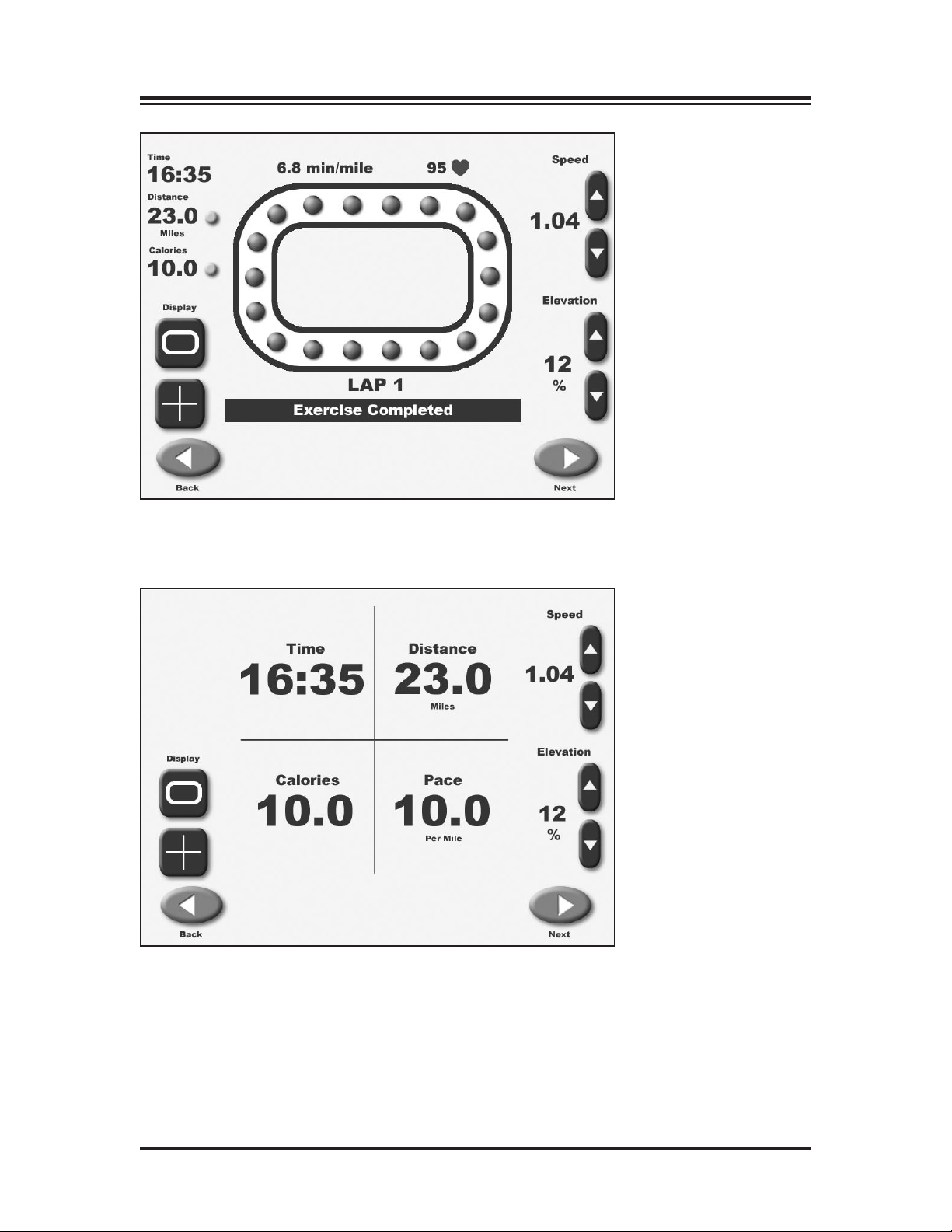
MANUAL MODE EXERCISE TRACK AND NUMERIC DISPLAY PARAMETERS
(See Figures 8.3 and 8.4.)
The same parameters are displayed on both the Exercise Track and Numeric displays. A brief
explanation of these parameters follows.
Time: Counts down in minutes and seconds the total time entered for the exercise on the Setup
Options screen.
Distance: Displays the distance in miles or kilometers that the patient is expected to complete in
the exercise session.
Calories: Toggle between:
• Calories: Total calories burned by the user during the exercise session.
• Calories/Hr: Calories that will be burned per hour at the current pace.
• MET
Oxygen consumption of a seated individual at rest. Thus, a seated individual in a resting state is
consuming one MET. A seated individual exercising at a rate of two METs is consuming twice the
Oxygen of a seated, resting individual. A person exercising at 10 METs is consuming ten times the
Oxygen of a seated, resting individual. To compute the METs of a person actively exercising on
the Gait T
Medicine Guidelines for Testing and Exercise. The METs value is always displayed in real/time
for current speed.
Select Direction: Use the <Forward> and <Reverse> icons to select the desired treadbelt direction.
Pace: The amount of time it will take the user to move one mile or KM at the current treadbelt
speed.
s: This value reflects the resting rate of Oxygen consumption with one MET equal to the
rainer 2, the system uses standard calculations based on American College of Sports
TREADMILL OPERATION — 8-4 —
Page 23
CONTENTS
Figure 8.3. The Exercise Track display.
Figure 8.4. The Numeric display.
— 8-5 — TREADMILL OPERATION
Page 24

9. TREADMILL PROFILES
The Biodex Gait Trainer treadmill mode features five pre-loaded exercise profiles and the ability
to create and select up to 12 custom exercise profiles. These programs allow the clinician to select
re-determined exercise format routines. Exercise profiles are divided into as many as ten
p
segments each. Users can select any of the pre-defined exercise profiles, review or edit any exercise profile, or delete an existing exercise profile.
The pre-defined exercise profiles include:
• Anerobic
• Aerobic
• Pyrimiding
• Surge
• Random
CHOOSING A PRE-DEFINED EXERCISE PROFILE
(See Figures 9.1, 9.2 and 9.3.)
To choose a pre-defined exercise profile:
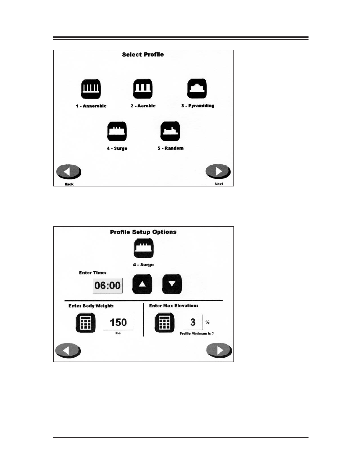
1. At the treadmill Opening Menu touch <Profile>. The Select Profile screen should now be displayed
2. Touch to select the desired pre-defined exercise profile. The Profile Setup Options screen
should now be displayed.
3. At the Profile Setup Options screen, enter the Time duration, user’s body weight, and the
maximum elevation for the exercise profile. Touch <Next> to advance to the Profile Exercise
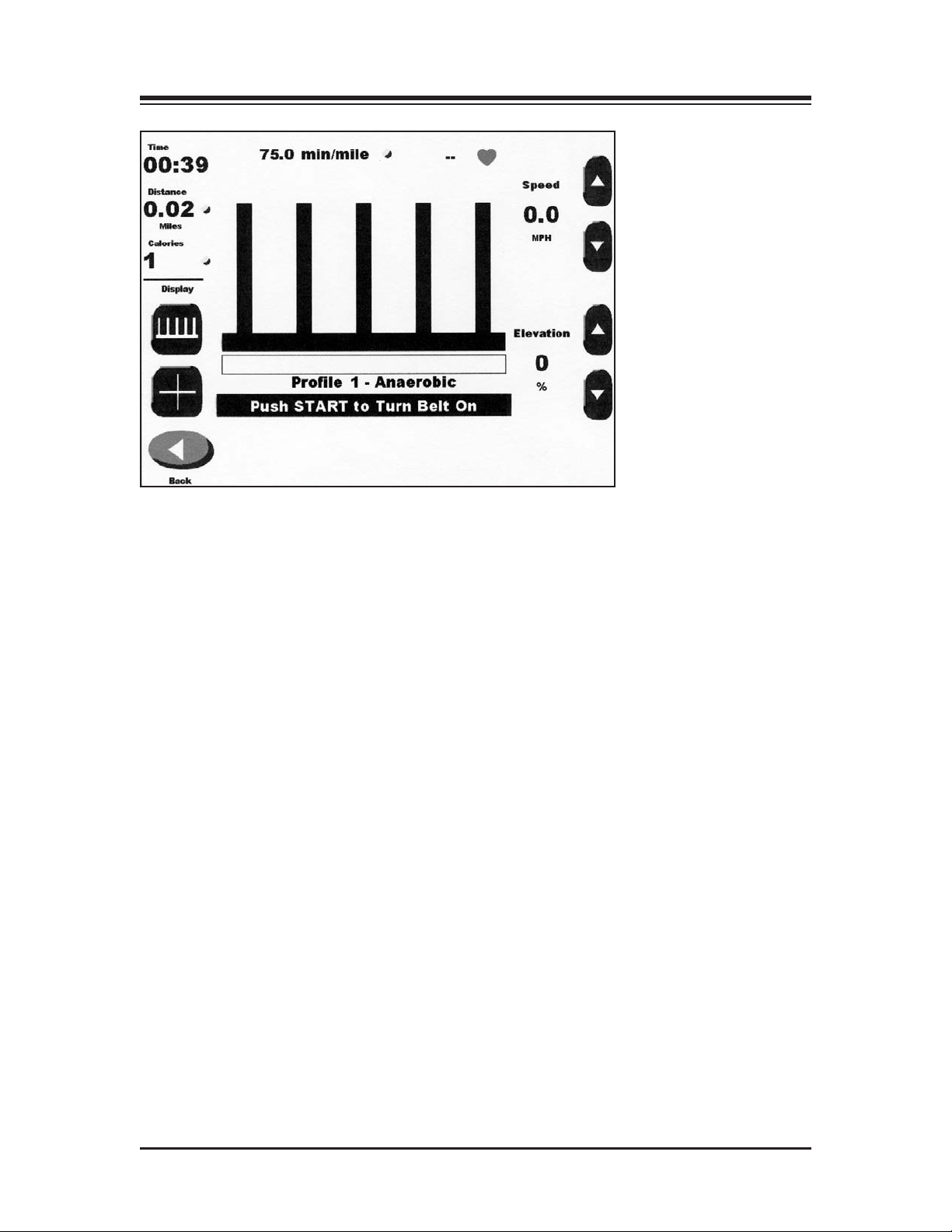
screen.
4. At the Profile Exercise screen, push <Start> on the display to activate the treadbelt and begin
the exercise session. The treadbelt will automatically ramp up to the speed required by the
first segment of the desired protocol. The treadmill will also automatically rise or lower to the
required elevation.
5. The treadmill will automatically beep to signal the end of each profile segment and then proceed to match the required speed and elevation for the next segment. If necessary, the <
and <▼> arrows on the Exercise Track or Numeric Display can be used to adjust the speed
and elevation setting at any time.
6. Touch <Pause> to pause the exercise session at any time. Press <Resume> to resume the exercise session.
7. Touch <End> to end the exercise session at any time.
8. Touch <Reset> to return to the Opening screen.
9. Touch <Reset> to return to the Opening screen.
▲>
— 9-1 — TREADMILL PROFILES
Page 25
CONTENTS
Figure 9.1. The Select Profile screen allows the user to choose from five
pre-defined profiles.
Figure 9.2. At the Profile Setup Options screen, users can enter values for
time, body weight and maximum elevation.
TREADMILL PROFILES — 9-2 —
Page 26
CONTENTS
Figure 9.3. Ready to begin an exercise session with Profile 1, Anaerobic, selected.
DESIGNING A CUSTOM EXERCISE PROFILE
(See Figure 9.4.)
To design a custom exercise profile:
1. At the treadmill Opening Menu touch <Profile>. The Select Profile Menu should now be displayed
2. Touch option six, <Custom>. The Custom Profiles screen should now be displayed.
3. Touch <Edit Profile> and then enter the number (1 – 12) of the profile you would like to
design. Touch <OK>. The Editing Profile screen should now be displayed with the number
of the profile you have decided to design.
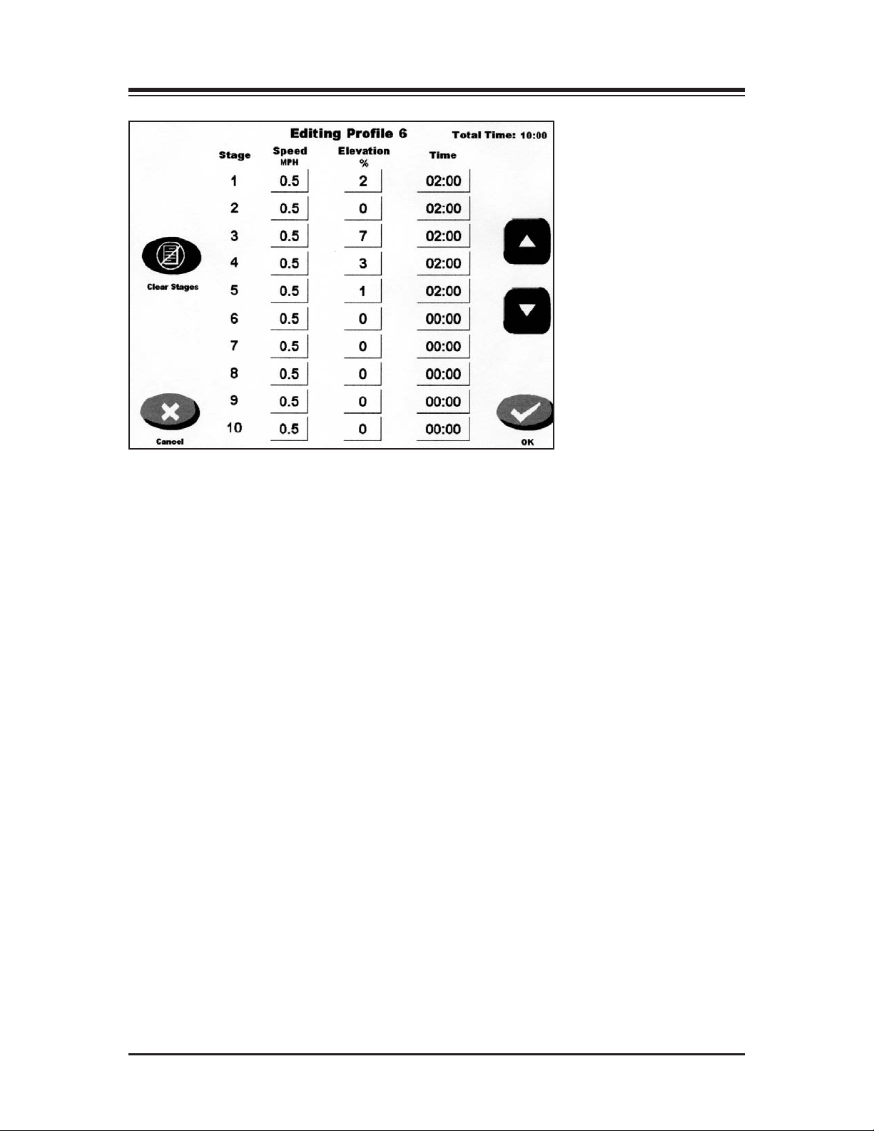
Each exercise profile can be divided into as many as ten separate stages. Enter the speed, ele-
4.
vation and time duration for each stage. If you make a mistake and need to clear the stages,
touch <Clear Stages>. Touch <OK> to return to the Custom Profile menu.
5. At this point, you can touch to select any of the custom profiles designed. The Custom Profile
Setup Options screen should now be displayed. Proceed as if using a pre-defined profile.
— 9-3 — TREADMILL PROFILES
Page 27
CONTENTS
Figure 9.4. At the Editing Profile screen, clinicians enter values for speed,
elevation and time for each of up to ten stages for any profile.
TREADMILL PROFILES — 9-4 —
Page 28
10. GAIT TRAINER 2 UTILITIES
(See Figure 10.1)
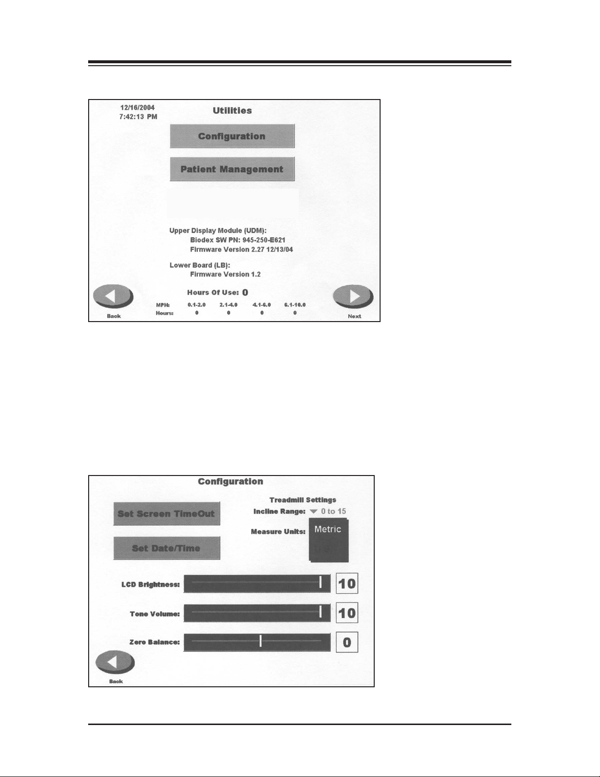
Figure 10.1. The Utilities Menu allows access to the Configuration and Patient Management screens. The
System Maintenance screen, not displayed, is also accessed through the Utilities Menu.
The Utilities Menu allows users to access the Configuration, Patient Management and System
Maintenance (not shown) screens. The Utilities Menu also displays technical information about
the Gait Trainer 2, firmware version, and cumulative hours of use.
To access the Utilities Menu, touch <Utilities> on the Main. The Utilities Menu should now be displayed.
CONFIGURATION
(See Figures 10.2 and 10.3.)
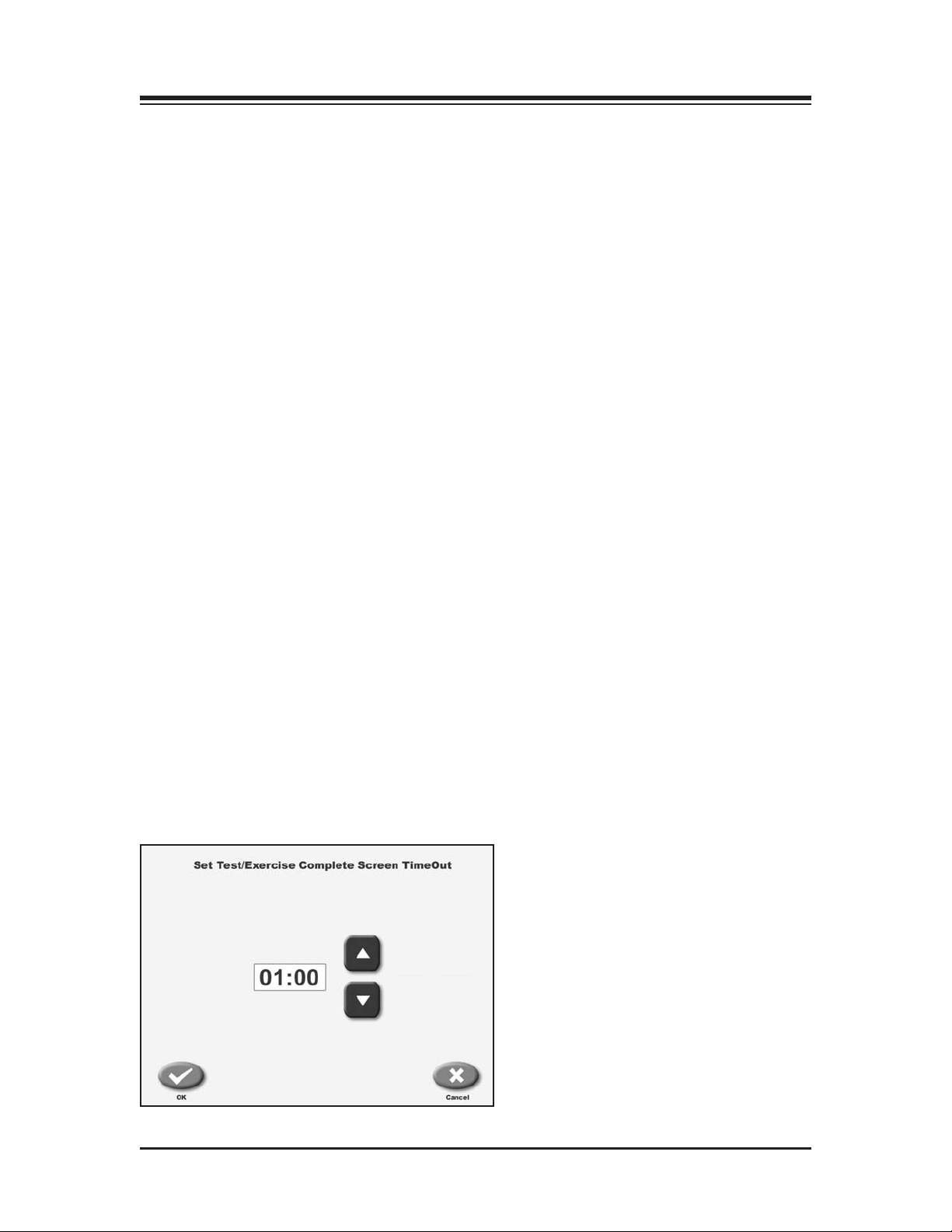
Figure 10.2. The Configuration screen.
— 10-1 — GAIT TRAINER 2 UTILITIES
Page 29
CONTENTS
To advance to the Configuration screen from the Utilities Menu, touch <Configuration>. Enter 781
at the “Access ID Code” prompt and touch <OK>. The Configuration screen should now be displayed. This screen allows the user to choose between various display options and to set specific
parameters for a variety of treadmill functions.
Following is a description of Configuration screen options. Once all parameters and values are set
as desired, touch <Back> to exit and return to the Utilities Menu. Touch <Back> again to return to
the Main Menu.
Configuration Screen Parameters
Set Screen Time Out: Touch this option to advance to the Set Test/Exercise Complete Time Out
Screen. This setting determines how long the Exercise Results screen will be displayed before the
screen saver kicks in following completion the exercise session. Default is 1:00 minute but the
range can be adjusted from 0:00 to 30:00 minutes. Touch the <▲>or <▼> icons to increase or
decrease the value. Touch <OK> to continue and return to the Configuration screen.
Set Date/Time: Touch <Set Date/Time> to change the system time or date. Touch to highlight the
value to change, then use the <
<OK> to return continue and return to the Configuration screen.
LCD Brightness: Touch any section of the horizontal bar to select a new brightness setting. Selecting
low numbers along the bar will result in a darker screen while selecting high numbers makes the
screen appear brighter. Brightness levels range from 1 to 15.
▲>or <▲> icons to increase or decrease the value as desired. Touch
Tone Volume: Touch any section of the horizontal bar to select a new tone volume setting. Selecting
low numbers along the bar will result in lower volume while selecting high numbers makes the
louder. Tone volume settings range from 0 to 10.
Zero Balance: This feature is used to eliminate treadbelt “creep” (slow movement of the treadbelt
while the speed is set to zero.) Select negative values to zero out forward treadbelt creep and positive values to zero out reverse belt creep.
Note: Belt Movement While at Zero Speed
Inherent "belt creep" is common with Pulse Width Modulation Motor Control. Allow the treadmill sufficient time to "warm up" prior to making any adjustments for belt creep.
Incline Range:
ouch the displayed value to show both options and then touch the desired setting to select.
T
Measure Units: The Biodex Gait Trainer 2 can be configured to display either U.S. or metric mea-
ements. To change units, touch the displayed units and then touch the desired setting to select.
sur
The Biodex Gait Trainer 2 comes with a choice of 0 to 15 or –3 to 12 degrees of incline.
Access Pr
protection requires entry of an I.D. code (781)
to access custom profiles. Touch the displayed
value to show both options, then touch the
desir
otection for Custom Pr
ed setting to select.
ofiles:
Access
Figure 10.3. The Set Test/Exercise Complete Screen Time Out screen.
GAIT TRAINER 2 UTILITIES — 10-2 —
Page 30
CONTENTS
PATIENT MANAGEMENT
(See Figurs 10.4 and 10.5.)
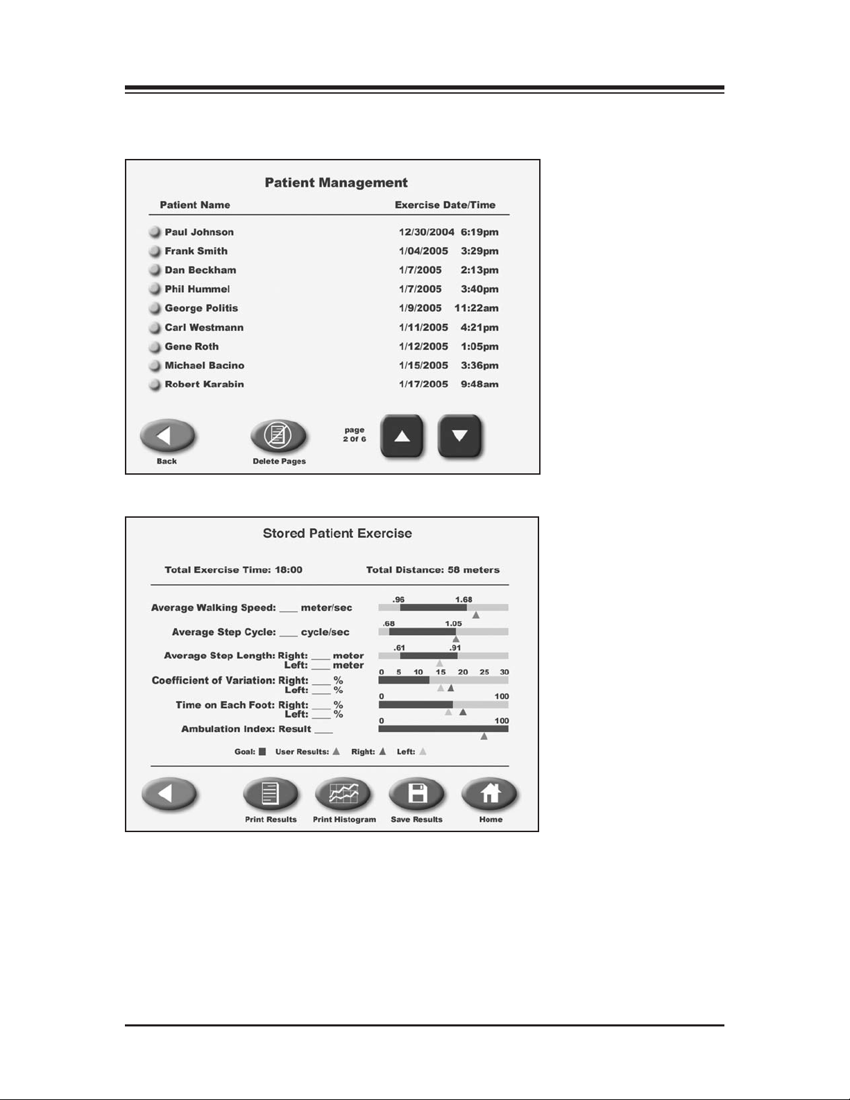
Figure 10.4. The Patient Management screen.
Figure 10.5. The Stored Patient Exercise screen.
To advance to the Patient Management screen from the Utilities Menu, touch <Patient
Management>. Enter 781 at the “Access ID Code” prompt and touch <OK>. The Patient
Management screen should now be displayed.
— 10-3 — GAIT TRAINER 2 UTILITIES
Page 31

CONTENTS
Patient Management functions include the ability to delete an individual patient file, multiple
patient files, print a stored exercise report, print a stored patient histogram and export patient
ata. A description of each feature follows.
d
Deleting Patient Files
To Delete An Entire Page of Patient Files:
1. Touch the <Delete Page> icon. The system will ask if you are sure you want to delete the
selected files. Touch <Yes>. The selected files are deleted and the system returns to the Patient
Management screen.
To Delete A Single Patient File:
1. Touch to highlight the patient file to delete. The Stored Patient Exercise screen should now be
displayed showing the selected patient file.
2. Touch <Delete> to delete the selected patient file. The system will ask if you are sure you want
to delete the selected file.
3. Touch <Yes>. The selected file is deleted and the system returns to the Patient Management
screen.
Printing Stored Patient Files and Histograms
1. To Print a Stored Patient File or Histogram:
2. Touch to highlight the patient file to print. The Stored Patient Exercise screen should now be
displayed showing the selected patient file.
3. Touch <Print Record> to print out the patient file, or touch <Print Histogram> to print out a
patient histogram. After printing, the system returns to the Stored Patient Exercise screen.
Exporting Patient Footfall Data
The Export Patient Data function allows patient footfall data from a stored test to be exported in
CSV format.
To Export A Patient Data File:
1. Connect a RS-232 cable to the Auxiliary Com Port on the back of the display panel, and to
your computer or laptop.
NOTE: You will need to use a Terminal Emulation Program, such as Windows Hyperterminal, to
export the data. Set your program to accommodate the follwing:
• Baud Rate: 19,200
• Data Bits: 8
• Parity: 0
• Stop Bits: 1
• Flow Contr
• Com Port: 1, 2, etc.
2. Touch to highlight the patient file to export. The Stored Patient Exercise screen should now be
displayed showing the selected patient file.
3. Touch <Export> to export the patient footfall data. After completing the export procedure, the
system returns to the Stored Patient Exercise screen.
ol: 0
GAIT TRAINER 2 UTILITIES — 10-4 —
Page 32

CONTENTS
SYSTEM MAINTENANCE
he System Maintenance screen is hidden from normal view. This screen, when active, allows the
T
user to select the treadmill type (Gait Trainer or RTM 600), perform speed and elevation calibration, and perform strain gauge calibration.
To access the System Maintenance screen:
1. Press the ON/STANDBY button on the treadmill display.
2. Touch <Utilities>.
NOTE: The next step requires pressing the hidden keypads in the upper right and left corners of the
displays touch screen.
3. Touch the top right corner of the Utilities screen, the top left corner, and the top right corner
successively to access the <System Maintenance> prompt on the display.
4. Touch <System Maintenance>. The System Maintenance screen should now be displayed.
Speed and Elevation Calibration
Speed Calibration
1. From the System Maintenance screen, touch <Treadmill Diagnostic Display>.
2. Adjust the balance (BAL) Pot on the PWM (945-275-E350) board for no belt movement at
0 mph.
3. Set the speed to 10 mph and adjust the Gain Pot on the PWM (945-275-E350) for a reported
speed of 10 mph.
4. Touch <Back> to return to the System Maintenance screen.
Elevation Calibration
1. From the System Maintenance screen, touch <Treadmill Diagnostic Display>.
2. Touch ▼ for the elevation until the elevation motor stops.
The reported elevation counts should be between 12-15. If not, loosen the
nut on the elevation pot and adjust the pot for a count between 12-15.
3. Touch
4.
Strain Guage Calibration Procedure
NOTE: This procedure should be used only when a problem exists and the user has been advised by the
Biodex Service Department.
Power Up
1. Plug in the power cord of the treadmill.
2.
3. Verify that LED D5 on the strain gauge board blinks. Ignore all other LED’s at this point.
Zero Mode Programming/Calibration
4. Press the following switches in sequence: S4, S2, S3, S1. Note that the corresponding LED’s
5. Press any one of the S1 - S4 switches to turn off D1 - D4, then verify that LED’s D1 – D4 each
6. Verify that LED’s D2 and D4 turn on again denoting "underweight" and "no weight."
▲ until the treadmill is fully elevated. The counts should be between 121-125.
Touch <Back> to return to the System Maintenance screen.
Turn on the power switch at the bottom of the treadmill near the power cord.
NOTE: Do not touch or stand on the treadmill belt while the auto-zero calibration is being performed.
D4, D2, D3, D1, will light and stay on with each switch press.
turn on sequentially as each strain gage is auto-zeroed, then LED’s D1 – D4 all turn off when
auto-zero calibration is completed.
— 10-5 — GAIT TRAINER 2 UTILITIES
Page 33

CONTENTS
Enter Strain Guage Calibration Screen
7. Press the ON/STBY button on the treadmill display.
. Press "Utilities."
8
Note: The next step requires pressing the hidden keypads in the upper right and left corners of the
displays touch screen.
9. Touch the top-right corner, top-left corner and then top-right corner successively to access
the "System Maintenance" menu on the display.
10. Press "System Maintenance."
11. Select "Treadmill Diagnostic Display."
Zero Setting
12. The strain gauge calibration screen shows the A/D counts for each gage located in each corner of the treadmill deck simultaneously. Verify that the calibration screen shows each gage
output to be between 0 and 10 counts when no one is standing on the treadmill.
Gain Mode Programming
13. Press the following switches in sequence: S2, S4, S1, S3. Note that the corresponding LED
will light and stay on with each switch press.
Gain Setting
Note: You must complete steps 14 through 26 in order to see the correct number of counts on the display for
each placement of the weight.
14. Place the 100-lb weight next to the right front side plate screw. The weight should be on the
belt and centered over the screw.
15. Press switch "S1." On the strain gauge board.
16. Verify that LED D1 turns on signifying successful calibration.
17. Place the 100 lbs next to the left front side plate screw. The weight should be on the belt and
centered over the screw.
18. Press switch "S2."
19. Verify that LED D2 turns on signifying successful calibration.
20. Place the 100 lbs next to the left rear side plate screw. The weight should be on the belt and
centered over the screw.
21. Press switch "S3."
22. Verify that LED D3 turns on signifying successful calibration.
23. Place the 100 lbs next to the right rear side plate screw. The weight should be on the belt and
center
ed over the screw.
24. Press switch "S4."
25. Verify that LED D4 turns on signifying successful calibration, then all LED’s should turn off.
26.
Place the weight in each corner and verify a count of approximately 200 for each strain gauge.
27. Touch "Back" on the display 3 times to return to the main screen.
GAIT TRAINER 2 UTILITIES — 10-6 —
Page 34
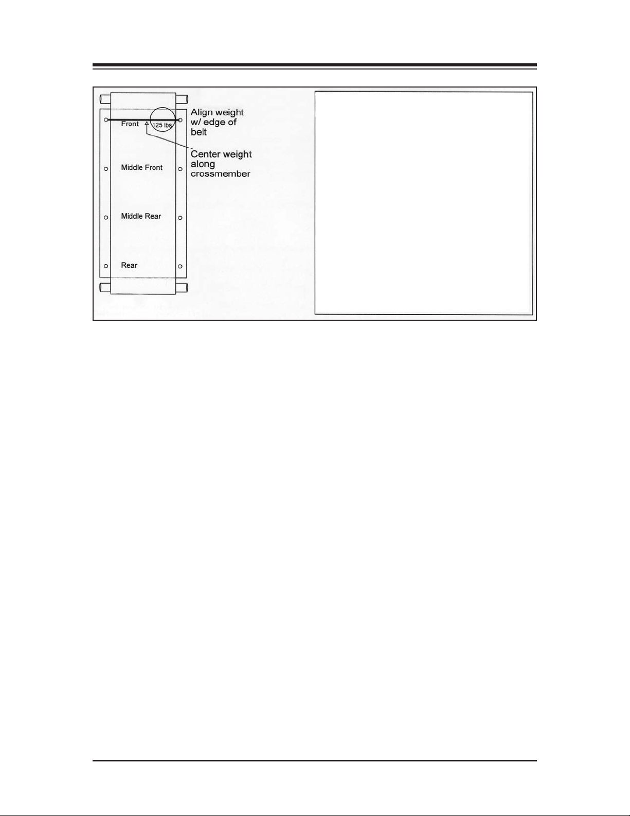
CONTENTS
Figure 10-6.
Strain Gauge Board LED Codes
D5 Should always be flashing. This means
the Microprocessor on the board is
working.
D4 Indicates no weight is on the Treadmill
when this LED is on.
D3 LED on = auto calibrate is in progress.
D2 LED on = Underweight.
D1 LED on = Overweight.
— 10-7 — GAIT TRAINER 2 UTILITIES
Page 35

11. MAINTENANCE
Your Biodex Gait Trainer 2 should provide trouble-free operation as long as the following
aintenance procedures are performed. Be sure to adhere to the hours of usage guidelines in the
m
chart below.
OTE: Without proper maintenance, excessive wear to drive components will occur. To assure trouble-free
N
operation, scheduled maintenance must be performed. Failure to adhere to the scheduled maintenance chart
below will void your warranty.
Instruction Hours of Usage
Lubricate Deck 75
Reverse Deck 1,000
Belt Replacement 1,000
Clean Motor and Amp 750
Front Roller Cleaning 375
DAILY MAINTENANCE
As required, clean all exterior surfaces, upholstery and restraining straps. Specialized vinyl cleaners or protectants are recommended for upholstery and cushions. Otherwise, use a solution of
warm water and mild detergent.
NOTE: DO NOT use solutions containing ammonia.
Hardware computer components should be wiped clean as needed using a soft rag dampened
with alcohol.
QUARTERLY MAINTENANCE
Lubricate Treadbelt and Slider Deck
The Biodex Lubricant Kit is designed to reduce friction between the treadbelt and the slider deck.
It is required for all institutional treadmills. Proper and timely application of the lubricant will
prevent premature failures due to excessive wear and load. Items affected by inadequate lubrication are the treadbelt, slider deck, motor, and motor controller.
ANNUALL
Reverse Exact-Track Bed
Reverse the Exact-T
used over. Once both sides have been used, the bed must be replaced.
Replace Treadbelt
Inspect Treadmill for cracks or tears. If none are found, continue to use. If any cracks or tears are
apparent, replace treadbelt.
Y OR EVER
Y 1,000 HOURS
rack bed. The Gait Trainer bed is double-sided, allowing it to be reversed and
— 11-1 — MAINTENANCE
Page 36
CONTENTS
MAINTENANCE PROCEDURES
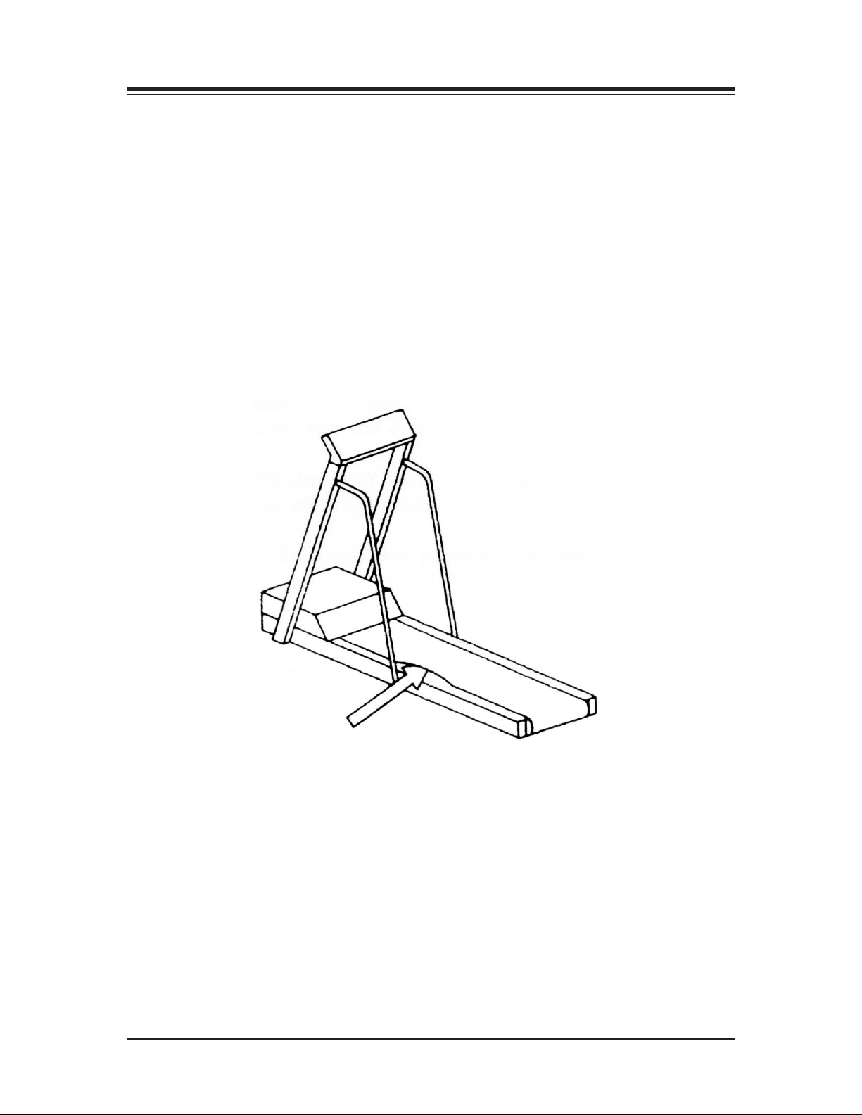
elt/Deck Lubrication
B
(See Figure 11.1.)
. Using the large syringe provided, squirt one-half tube of the lubricant underneath the center
1
of the treadbelt.
2. Walk 10 steps on the Gait Trainer at a speed of 1.0 mph. This will moisten an 8” track underneath the center of the entire treadbelt.
3. Allow the Gait Trainer to dry for approximately 10 minutes.
NOTE: Use only the Biodex lubricant kit with your Gait Trainer. Most standard greases, waxes and silicon
sprays will build up on the rollers, causing belt slippage and affecting tracking.
To re-order lubricant kit, use Biodex part # 945-276. Each container provides 12 applications.
Figure 1
Reverse or Replace Treadbelt and Deck
Tools Required: Phillips Screwdriver, 9/16 Socket, 3/16 and 5/32 Allen Wrench
1. Elevate treadmill to 10 degrees, allowing access to the underside of the Gait Trainer.
2. Remove power cord from wall outlet.
3. Remove motor cover secured by the six Phillips head screws. Once screws are removed, lift
4. Remove motor tension lock nut, located on the underside of accessory pan. The nut is attached
MAINTENANCE — 11-2 —
1.1. Squirt one-half tube of lubricant between the belt and deck.
emove cover.
and r
to the motor bracket tensioning bolt. Once the tensioning bolt has been r
up and remove motor drive belt.
emoved, lift the motor
Page 37
CONTENTS
!
!
!
!
5. Remove the two aluminum traction strips, located one on each side of running deck. These
re secured by four Allen screws located on top of traction strips.
a
6. Remove rear treadbelt roller. The roller is secured by two treadbelt tensioning bolts. Once
olts have been removed, lift out the roller assembly.
b
. Remove the two Allen screws which secure the front treadbelt roller. The screws are located
7
on the side of the Gait Trainer.
CAUTION: When the bolts securing the roller are removed the roller will drop. Be aware that the
rollers are heavy.
ATTENTION: Si les boutons de sécurité du rouleau sont retirés, le rouleau chutera. Ne oas oubli-
er que les rouleaux sont lourds.
8. Remove the running deck. This is done by lifting from the side of the deck and raising the
deck two inches before sliding it out. The running deck is two-sided and can be flipped over
and reused once.
9. To remove the treadbelt seven support brackets must be removed. These are comprised of three
angle iron brackets attached by securing nuts, and four running deck support bars secured by
Allen screws. Once all support brackets are removed the treadbelt can be removed.
10. Tension treadbelt and adjust tracking after you reassemble the Gait Trainer. (See Treadbelt
Adjustment procedure.)
Treadbelt Adjustment
Although the Gait Trainer incorporates the “Exact Track System,” occasional belt adjustments are
still necessary for correct tensioning and tracking.
Tension Adjustment
CAUTION: Before testing treadbelt tension as described below, turn the Gait Trainer OFF and
unplug the system. Moving parts on the Gait Trainer can cause serious injury. Do not attempt to
determine treadbelt tension while the belt is moving.
ATTENTION: Avant de tester la tension du tapis selon la procédure décrite ci-dessons, méttre le
tapis à l’arrêt et déconnecter le câble secteur
blessures graves. Ne jamais essayer de déterminer la tension sur le tapis pendant que ce dernier est
en mouvement.
The need for tension adjustment is indicated by uneven belt speed or the belt stopping suddenly
upon foot impact. Properly tensioned, the treadbelt will allow the user to slip a hand snugly under
the center of the belt.
Treadbelt tension is adjusted by tightening or loosening the two hex-head, 9/16, bolts at the end of
the Gait T
amount, in the same direction. Turn both bolts clockwise to tighten the belt. Turn both bolts counterclockwise to loosen the belt. Failure to turn both bolts equally may affect tracking. One quick test
is to apply hand heel strikes and observe if belt momentarily stops. If belt speed remains constant,
this indicates belt is tight. If belt hesitates during heel strikes, additional tightening is required. To
check over tightening, set Gait Trainer to .5 mph and, while holding rail, resist until belt stops. If
drive r
roller stops when belt is stopped, belt is too tight. Loosen belt and recheck.
rainer frame. The bolts should be adjusted in 1/4-turn increments, exactly the same
oller continues to rotate with the belt stopped, further adjustment is not necessary. If drive
. Certaines piéces du tapis peuvent entrainer des
— 11-3 — MAINTENANCE
Page 38

CONTENTS
Tracking
racking adjustment is necessary when a pronounced bump appears toward the left side of the
T
belt, approximately two inches from the left edge. This occurs when the belt works its way out of
he Exact-Track grooves.
t
To Adjust Treadbelt Tracking:
Tighten the hex tensioning bolt on the side to which the treadbelt has migrated, turn bolt in 1/8
increments clockwise. The tread belt should slowly move away from the tightened bolt. Once belt
migrates back into roller slot the bump will disappear. At this point, fine tracking adjustment is
necessary.
Fine Tracking
Fine tracking adjustment prevents premature wear of the tacking belt rib which rides in the ExactTrack groove. The belt rib should be centered in the tracking groove. If the rib rides against the
groove wall, a friction point forms causing excessive wear. This adjustment should be made during preventative maintenance or during belt replacements.
To Adjust Fine Tracking:
Determine which side of the exact track groove the belt rib is riding on. Mark treadbelt tracking
position on deck.
Tighten the hex tensioning bolt on the side the belt is tracking against, belt should migrate to the
opposite side of the groove. Mark the treadbelt tracking position on the deck. You now have two
marks on the deck 1/4” apart. Mark the center position of the marks. This is where the belt should
track. Adjust 9/16 tensioning bolt so that the belt is centered on the mark. Remember the belt will
migrate away from the tension bolt that is adjusted last. Tracking adjustments are done in forward
direction only, at 8 mph.
Check tensioning after adjustment to ensure proper belt performance and wear.
NOTE: Motor drive belt should never slip. Check this when you check for treadbelt overtightening. If treadbelt drive roller is stopped, motor should also stall. If motor turns, but drive roller is stopped, tighten motor
tension bracket located under the mill. Adjust until the motor belt stops slipping.
MAINTENANCE — 11-4 —
Page 39

12. TROUBLE-SHOOTING
SYMPTOM
ait Trainer is turned ON and speed control is inoperable (belt not moving).
G
. Check for faults on display unit before moving onto step #2. The following diagnostic
1
rror codes apply:
e
CODE DESCRIPTION
128 Communication between upper/lower board inop
64 Safety Lanyard Removed
32 Control fault (no amplifier)
16 Grade Error
8 Motor Tach Output Exceeds Selected Speed
4 Motor Tach Output is Below Selected Speed
1 Hall Sensor Output is Below Selected Speed
2. If no faults are displayed check the following:
• Large blue capacitor should measure 170 VOL across terminals. If OK, proceed to step 3.
• Speed control signal on motor amplifier should measure .250 VDC per mill per hour E.G.
NOTE: Measurement taken at J1 Pin 1 PIN 2
1mph = .250 VDC
2mph = .500 VDC
4mph = 1.00 VDC
8mph = 2.00 VDC
If speed control signals are OK, proceed to step 3.
3. Check Amplifier Output. The Output Terminals are located on top of amplifier and are
designated “m+” and “m-”. The Output voltage should be: 1mph = 32 VAC, 2mph = 52 VAC
NOTE: Remember to use the volts A.C. selection on your meter
modulating, therefore A.C. scale is required.
If amplifier output is OK, proceed to step 4.
Check Motor Resistance. The motor has a winding r
4.
value is dependent on commutation position. If resistance reading is significantly higher
the windings or brush contacts are defective.
To measure resistance turn Gait Trainer power OFF. Place meter lead across terminals
marked “m+” and “m-”. Set meter scale to the lowest resistance selection. Check resistance
in several commutator positions by rotating motor shaft 9.0 degrees for every one revolution.
. The Amplifier is pulse width
esistance of 1.3 to 3 Ohms. The
— 12-1 — TROUBLE-SHOOTING
Page 40
13. OPTIONAL
!
!
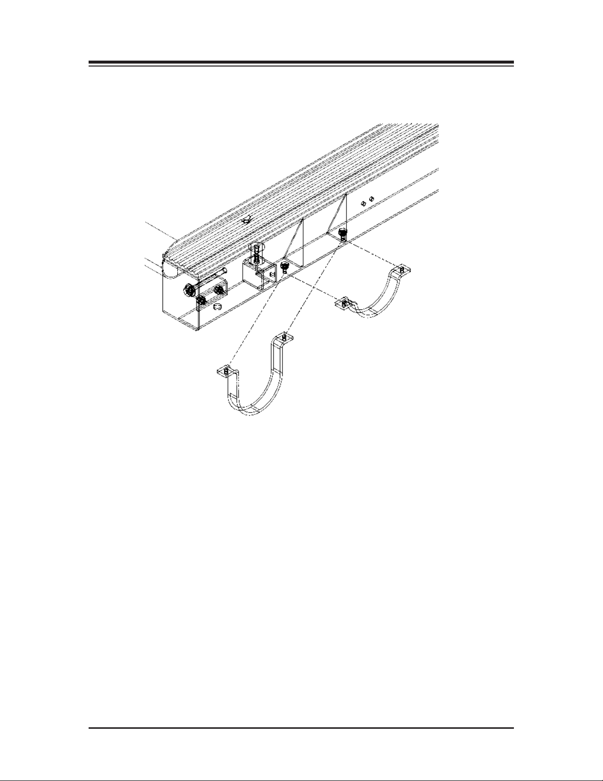
INSTALLING THE ELEVATION ROCKERS
See Figure 13.1.)
(
he Gait Trainer is available with Incline/Decline of either standard 0 to 15 degrees or optional -3 to
T
2 degrees (Part# 945-275-M315). This setting is preset at the factory prior to shipping.
1
CAUTION: This procedure requires the efforts of at least two strong individuals.
ATTENTION: Cette installation nécessite au moins deux personnes en bonne santé.
1. Press <STANDBY> to turn the Gait Trainer to the Standby mode. Turn the Power Switch,
located at the base of the Gait Trainer in the left corner at the display end, to the “0” (OFF)
position. Unplug the Gait Trainer.
2. With the aid of a second person, gently tip the Gait Trainer over on one side.
3. Using a 7/16” wrench, remove the two bolts that secure each rocker to the Gait Trainer frame.
4. Replace the existing rockers with the new rockers, replace the bolts and tighten until fully
secure.
5. With the aid of a second person, rotate the Gait Trainer back to the upright position.
6. Plug in the Gait Trainer 2 power cord.
7. Press <On/Standby> to turn ON the Gait Trainer 2.
8. From the Gait Trainer 2 Opening Menu, touch <Utilities> to display the Utilities Menu.
9. Touch <Configuration> and then enter 781as the access I.D. code. Touch <OK> to display the
Configuration Menu.
10. Under treadmill settings in the top right corner of the Configuration screen, 0 to 15 should be
displayed as the Incline Range.
10. Touch the displayed <Incline Range> value to toggle to -3 to 12.
1. Touch <Back> to return to the Utilities Menu.
1
ouch <Back> again to return to the Opening Menu. The Gait Trainer 2 should now be con-
T
12.
figured for -3 to 12 degrees elevation.
— 13-1 — OPTIONAL
Page 41
CONTENTS
Figure 13.1. Installing the optional Elevation Rockers.
OPTIONAL — 13-2 —
Page 42

14. ELECTROMAGNETIC COMPATABILITY
NOTE: This MEDICAL ELECTRICAL EQUIPMENT needs special precautions regarding EMC and
eeds to be installed and put into service according to the EMC information provided in the
n
ACCOMPANYING DOCUMENTS.
OTE: Portable and mobile RF communications equipment can affect MEDICAL
N
ELECTRICAL EQUIPMENT.
NOTE: Contact Biodex Medical Systems for additional EMC information.
ELECTROMAGNETIC COMPATIBILITY FOR GAIT TRAINER 2
Standard Test Method Range Limits Result
IEC 61000-3-2 Harmonics 100 Hz to 2KHz Class A THD = 57.54%
IEC 61000-3-3 Flicker observation time (TP) 10 min - -
IEC 61000-4-2 Electrostatic
Discharge Contact: 4 & 6Kv pos/neg 1pps no degradation complied
IEC 61000-4-3 Radiated
IEC 61000-4-4 Electrical Fast PWR Input leads .5, 1, & 2 no degradation complied
IEC 61000-4-6 Conducted 150 KHz to 80 MHz /3Vrms no degradation complied
IEC 61000-4-8 Magnetic 3A/M RMS @ 50/60 Hz no degradation complied
IEC 61000-4-11 Voltage Dips
CISPR 11 Conducted 150 KHz - 500 KHz /5 MHz - 30 MHz, 79/73 dbuV QP complied
CISPR 11 Radiated 30 MHz – 230 MHz /230MHz - 1GHz, 40/47 dbuVm complied
IEC 61000-4-5
Immunity 80 MHz to 2500 MHz / 3v/m Horiz no degradation complied
Transient/Burst, Kv / pos & neg / 5KHz of performance
Power Leads Rep Rate
Immunity, of performance
Power Leads
Immunity of performance
and Interrupts Int Pause % no degradation complied
Emission Class A, Group 1 66/60 dbuV AV
Emissions Class A, Group 1 @ 10 m
ge
Sur
Immunity, 1ppm 5 Pos, of performance
Power Leads 5 Neg for total of 10
max voltage change (dmax) 4% .45%
max Rel steady state voltage 3% .14%
change (dc) duration of d(t)>3%(t) .2 sec 0.00 sec
short term flicker Sev (PST) 1.00 .24
long term flicker Sev (PLT) .65 .23
for 10 sec of performance
Air: 2, 4, & 8Kv pos/neg 1pps
for 10 sec
& Vertical @ 1M of performance
eduction of performance
Duration between
Int 20msec pause 10 sec >95% no degradation complied
Int 100msec
Int 500msec pause 10 sec 30% no degradation complied
Int 5000msec pause 10 sec >95% no degradation complied
1 Kv, differential, 2 Kv Commons, no degradation complied
pause 10 sec
r
of performance
60% no degradation
of performance
of performance
of performance
complied
— 14-1 — ELECTROMAGNETIC COMPATIBILITY
Page 43

15. SPECIFICATIONS
Dimensions: 86" l x 27" w (218 x 69 cm)
Walking Area: 64" l x 20" w (160 x 51 cm)
rinter Stand: 24" l x 24" w (61 x 61 cm)
P
Motor: 2 HP with 4Q-Pulse Width Modulation Control
Speed Range:
Forward: 0-10 mph (0-16.9 km/h)
Reverse: 0-3 mph (0-4.8 km/h) in
0.1 mph (.16 km/h) increments
Elevation: 0-15% Grade or -3 to 12% Grade
Heart Rate Monitoring: Polar
Deck: 1" thick (2.5 cm) Reversible Teflon™Impregnated High Density Composite Fiber
Power: 115 VAC, 50/60 Hz, 20 AMP dedicated line, or 230 VAC, 50/60 Hz, 20 AMP
dedicated line. Includes hospital grade plug with 12' (3.7 m) power cord.
User Capacity: Tested to 400 lb (182 kg)
Weight: 310 lb (140 kg)
Certification: ETL listed to UL 2601-1. ETL
conformity to M.D.D. 93/42/EEC specifications to meet all hospital requirements.
Warranty: 2-year parts, 1-year labor
®
Telemetry (Chest Strap) and contact handgrip
©
listed to CAN/CSA c22.2 No. 601-1-M90 CE
— 15-1 — SPECIFICATIONS
Page 44

16. REFERENCES AND BIBLOGRAPHY
REFERENCES:
1. Burchfeild, JB. Reading the Body’s Gas Guage. Advance for Providers of Post-Acute Care: April,
999, pp: 57-72.
1
2. Whittle, MW. Gait Analysis: An Introduction. Butterworth - Heinemann, Second Edition, 1997.
3. Sekiya, N., et al. Optimal Walking in Terms of Variablity in Step Length. JOSPT, Vol 26 (5): 266272, Nov. 1997.
BIBLIOGRAPHY:
BARBEAU, H, et al.
WALKING AFTER SPINAL CORD INJURY: EVALUATION, TREATMENT, AND FUNCTIONAL
RECOVERY Arch Phys Med Rehabili (80) 225-235, February 1999
Biodex #91-132
BEHRMAN, AL, et al.
LOCOMOTOR TRAINING AFTER HUMAN SPINAL CORD INJURY: A SERIES OF CASE
STUDIES Physical Therapy / Vol. 80 (7):688-700 / July 2000
Biodex #91-174
BOND, JM, et al.
GOAL-DIRECTED SECONDARY MOTOR TASKS: THEIR EFFECTS ON GAIT IN SUBJECTS
WITH PARKINSON DISEASE Arch Phys Med Rehabil, Vol. 81, January 2000
Biodex #91-149
BROUWER, B
STROKE SURVIVORS BENEFIT FROM STRENGTH TRAINING Biomechanics, Jan 2000
Biodex #91-147
CHIU, CC, et al.
ORTS AND AMBULATION OUTCOME IN PATIENTS WITH DUAL DIS-
INFLUENCING F
ABILITIES OF HEMIPLEGIA AND AMPUTA
Biodex #91-144
DEAN, CM, et al.
TASK-RELATED TRAINING IMPROVES PERFORMANCE OF SEATED REACHING TASKS
AFTER STROKE STROKE, Vol. 28(4):722-728
Biodex #91-155
FRIEDMAN, PJ
GAIT RECOVER
Biodex #91-158
GARDNER, M, et al.
PARTIAL BODY WEIGHT SUPPORT WITH TREADMILL LOCOMOTION TO IMPROVE GAIT
AFTER INCOMPLETE SPINAL CORD INJURY: A SINGLE SUBJECT EXPERIMENTAL DESIGN
, 78: 361-374, April 1998
PT
Biodex #91-122
ACT
ch Phys Med Rehabil, Vol. 81, Jan 2000
Ar
TION
Y AFTER HEMIPLEGIC STROKE Int Disabil Stud 12(3):119-22, Jul-Sept 1990
— 16-1 — REFERENCES AND BIBLOGRAPHY
Page 45

CONTENTS
GOLDIE, PA, et al.
DEFICT AND CHANGE IN GAIT VELOCITY DURING REHABILITATION AFTER STROKE
rch Phys Med Rehabil, Vol. 77:1074-1082 / Oct 1996
A
Biodex #91-142
PREDICTION OF GAIT VELOCITY IN AMBULATORY STROKE PATIENTS DURING REHABILITATION Arch Phys Med Rehabil, Vol. 80:415-420 / April 1999
Biodex #92-215
HESSE, S, et al.
RESTORATION OF GAIT BY COMBINED TREADMILL TRAINING AND MULTICHANNEL
ELECTRICAL STIMULATION IN NON-AMBULATORY HEMIPARETIC PATIENTS
Scand J Rehabil Med 27(4): 119-204 / Dec 1995
Biodex #91-159
RESTORATION OF GAIT IN NONAMBULATORY HEMIPARETIC PATIENTS BY TREADMILL
TRAINING WITH PARTIAL BODY-WEIGHT SUPPORT
Arch Phys Med Rehab 75(10):1087-93 / Oct 1994
Biodex #91-177
ASYMMETRY OF GAIT INITIATION IN HEMIPARETIC STROKE SUBJECTS
Arch Phys Med Rehabil, Vol. 78:719-724 / July 1997
Biodex #91-156
KUAN, TS, et al.
HEMIPLEGIC GAIT OF STROKE PATIENTS: THE EFFECT OF USING A CANE
Arch Phys Med Rehabil, Vol. 80 / July 1999
Biodex #91-145
LAUFER, Y, et al.
THE EFFECT OF TREADMILL TRAINING ON THE AMBULATION OF STROKE SURVIVORS
IN THE ARLY STAGES OF REHABILITATION Journal of Rehabilitation Research and
Development, Vol. 38, No. 1 / January/February 2001
Biodex #93-190
MACKO, RF, et al.
TREADMILL AEROBIC EXERCISE TRAINING REDUCES THE ENERGY EXPENDITURE AND
CARDIOVASCULAR DEMANDS OF HEMIPARETIC GAIT IN CHRONIC STROKE PATIENTS
Str
oke Vol. 28(2):326-330 / February 1997
Biodex #91-153
MALOUIN, F
USE OF AN INTENSIVE TASK-ORIENTED GAIT TRAINING PROGRAM IN A SERIES OF
PATIENTS WITH ACUTE CEREBROVASCULAR ACCIDENTS
Phys Therapy / Vol. 72(11): 781-793 / November 1992
Biodex #91-157
MORRIS, ME, et al.
STRIDE LENGTH REGULATION IN PARKINSON’S DISEASE NORMALIZATION STRATEGIES
AND UNDERLYING MECHANISMS Oxford Univ Press ./ Brain 119: 551-568 / 1996
Biodex #91-150
, et al.
REFERENCES AND BIBLOGRAPHY — 16-2 —
Page 46

CONTENTS
MULCARE, JA, et al.
PHYSIOLOGICAL RESPONSES DURING UNWEIGHTED AMBULATION: A PILOT STUDY
bstract PT – 78(5) / May 1988
A
Biodex #91-126
NADEAU, S, et al.
ANALYSIS OF THE CLINICAL FACTORS DETERMINING NATURAL AND MAXIMAL GAIT
SPEEDS IN ADULTS WITH A STROKE
Am J of Phys Med & Rehabil, Vol. 78(2): 123-130 / March-April 1999
Biodex #91-154
NELSON, AJ
DO WE NEED QUANTIFIED GAIT ANALYSIS IN THE CLINIC?….OR? WHAT’S THE SCORE?
Rehab & Therapy Products Review: 66-70, May/June 1998
Biodex #91-136
FUNCTIONAL AMUBLATION PROFILE Physical Therapy – 54 (10):1059-65, Oct 1974
Biodex #91-134
STRATEGIES FOR IMPROVING MOTOR CONTROL
Rehabilitation of the Head-Injured Adult – Chpt. 22: 313-334
Biodex #91-135
USING THE BIODEX UNWEIGHING SYSTEM, BALANCE SYSTEM AND GAIT TRAINER IN
AN INTEGRATED REHABILITATION PROGRAM Abstract, May 2001
Biodex #92-217
NIAM, S, et al.
BALANCE AND PHYSICAL IMPAIRMENTS AFTER STROKE
Arch Phys Med Rehabil, Vol. 8 / Oct 1999
Biodex #91-143
REYNOLDS, NC, et al.
ANALYSIS OF GAIT ABNORMALTIES IN HUNTINGTON DISEASE
Arch Phys Med Rehabil – Vol. 80: 59-65, Jan 1999
Biodex #91-137
ROTH, EJ, et al.
HEMIPLEGIC GAIT – RELA
RAL PARAMETERS CME Article – No. 6: 128-133
Biodex #91-152
SCHINDL, MR, et al.
TREADMILL TRAINING WITH PARTIAL BODY WEIGHT SUPPORT IN NONAMBULATORY
PATIENTS WITH CEREBRAL PALSY Arch Phys Med Rehabil, Vol 81:301-306, March 2000
Biodex #91-181
SEKIYA, N, et al.
OPTIMAL WALKING INT ERMS OF VARIABILITY IN STEP LENGTH
JOSPT, Vol (26) 5:266-272 / Nov 1997
Biodex #92-208
TIONSHIPS BETWEEN WALKING SPEED AND OTHER TEMPO-
— 16-3 — REFERENCES AND BIBLOGRAPHY
Page 47

CONTENTS
SHARP, SA, et al.
ISOKINETIC STRENGTH TRAINING OF THE HEMIPARETIC KNEE: EFFECTS ON FUNC-
ION AND SPASTICITY Arch Phys Med Rehabil, Vol 78 / Nov 1997
T
Biodex #91-148
STAMER, MH
TREATING GAIT DYSFUNCTION IN KIDS WITH CP
Advance for Directors in Rehabilitaton: 59-62 / June 1997
Biodex #91-133
SUZUKI, K, et al.
DETERMINANTS OF MAXIMUM WALKING SPEED IN HEMIPARETIC STROKE PATIENTS
Tohoku J Exp Med – 162(4): 337-344 / Dec 1990
Biodex #91-161
DETERMINANTS AND PREDICTORS OF THE MAXIMUM WALKING SPEED DURING COMPUTER-ASSISTED GAIT TRAINING IN HEMIPARETIC STROKE PATIENTS
Arch Phys Med Rehabil, Vol. 80: 179-182 / Feb 1999
Biodex #91-139
RELATIONSHIP BETWEEN STRIDE LENGTH AND WALKING RATE IN GAIT TRAINING FOR
HEMIPARETIC STROKE PATIENTS CME Article / No. 6: 147-152
Biodex #91-151
TEIXEIRA-SALMELA, LF, et al.
MUSCLE STRENGTHENING AND PHYSICAL CONDITIONING TO REDUCE IMPAIRMENT
AND DISABILITY IN CHRONIC STROKE SURVIVORS
Arch Phys Med Rehabil, Vol 80 / October 1999
Biodex #91-146
U.S. DEPT. OF HEALTH & HUMAN SERVICES
POST-STROKE REHABILITATION: ASSESSMENT, REFERRAL AND PATIENT MANAGEMENT Quick Reference Guide for Clinicians: No. 16
Biodex #91-141
VISINTIN, M, et al.
A NEW APPROACH TO RETAIN GAIT IN STROKE PATIENTS THROUGH BODY WEIGHT
SUPPORT AND TREADMILL STIMULATION Stroke – 29: 1122-1128 / 1998
Biodex #91-130
WAAGFJORD, J, et al.
EFFECTS OF TREADMILL
Phys Ther 70(9): 549-558, discussion 558-560 / Sept 1990
Biodex #91-160
WHITTLE, MW
GAIT ANALYSIS – AN INTRODUCTION (SECOND EDITION)
ISBN 0 7506 2222 9 Butterworth-Heineann / Linacre House / Jordan Hill, Oxford OX2 8DP
div. of Reed Educational & Professional Ppublishing Ltd.
Biodex #92-233
TRAINING ON GAIT IN A HEMIPARETIC PATIENT
REFERENCES AND BIBLOGRAPHY — 16-4 —
Page 48

CONTENTS
WOLFF, M, et al.
BEYOND STRIDE – OTHER CONSIDERATIONS WHEN DECIPHERING GAIT OF PEOPLE
ITH AMPUTATION Advance for Physical Therapists: 28-32 / March 9, 1998
W
Biodex #91-140
— 16-5 — REFERENCES AND BIBLOGRAPHY
Page 49
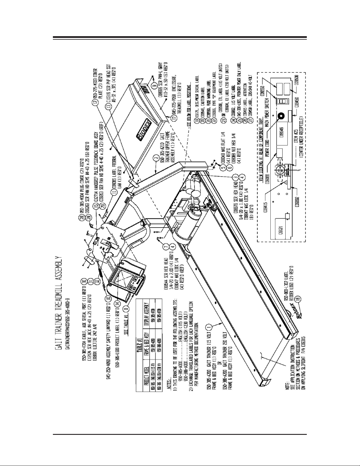
17. ASSEMBLY DRAWINGS AND SCHEMATICS
— 17-1 — ASSEMBLY DRAWINGS AND SCHEMATICS
Page 50
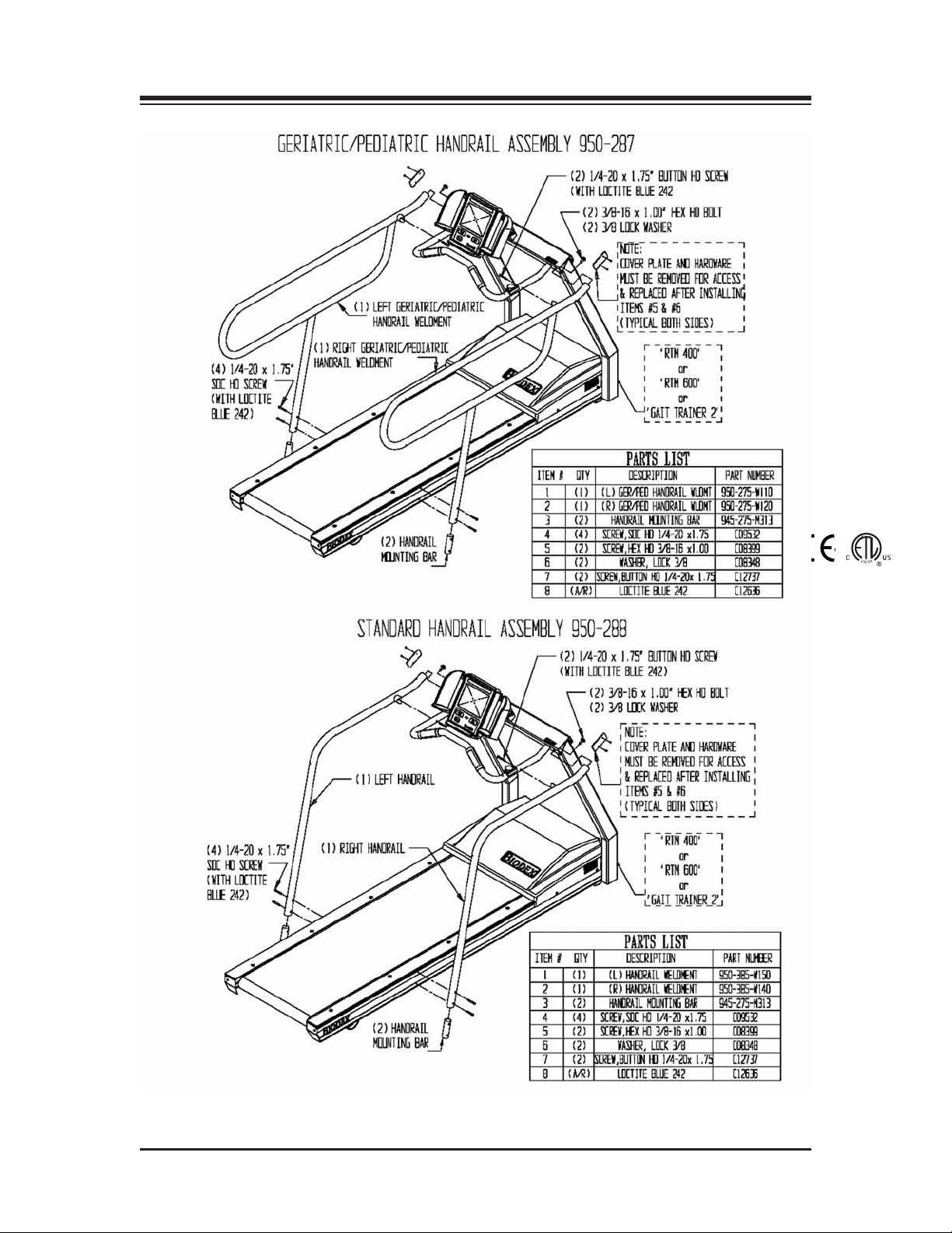
0413
CONTENTS
ASSEMBLY DRAWINGS AND SCHEMATICS — 17-2 —
Page 51
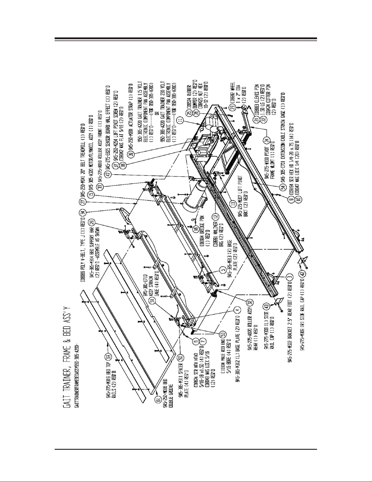
CONTENTS
— 17-3 — ASSEMBLY DRAWINGS AND SCHEMATICS
Page 52
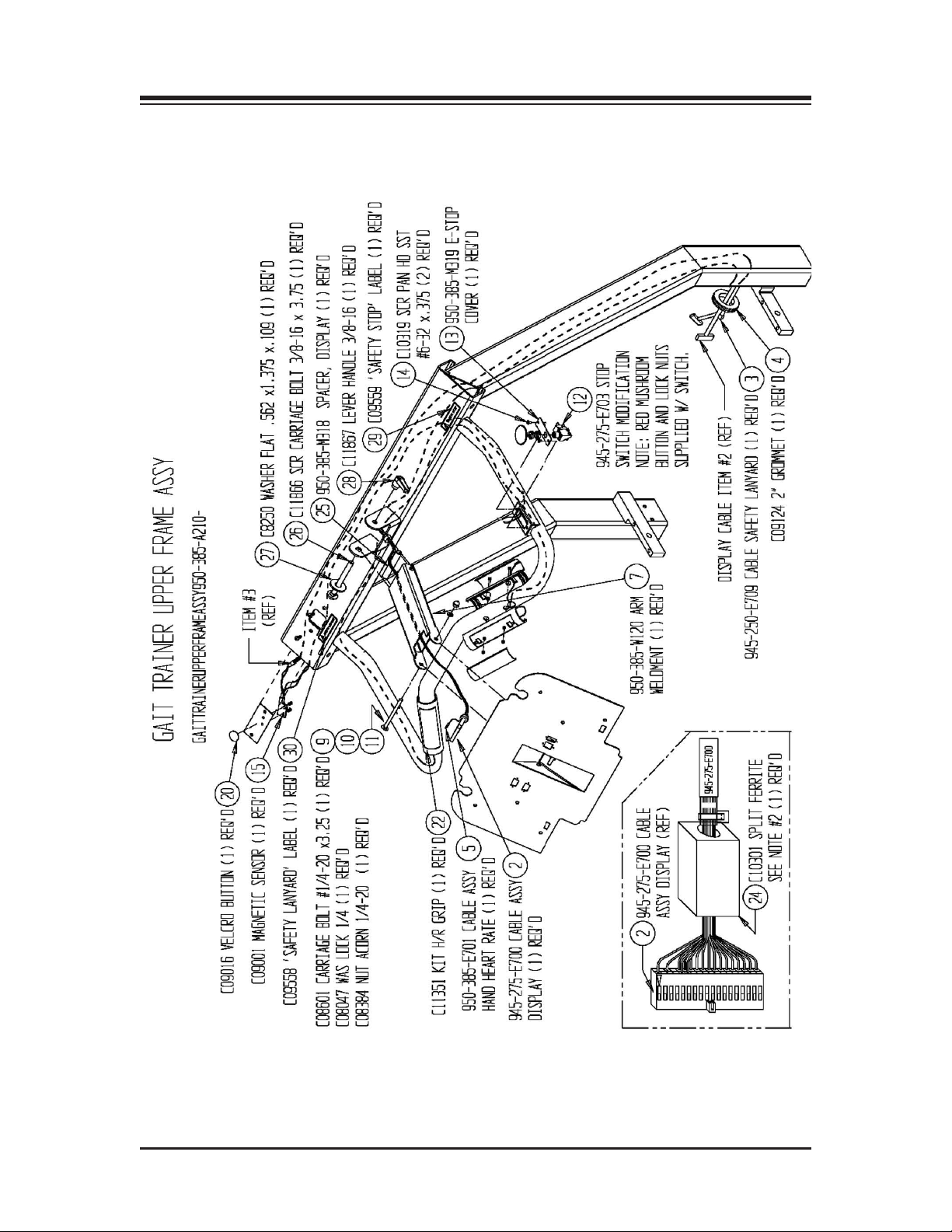
CONTENTS
ASSEMBLY DRAWINGS AND SCHEMATICS — 17-4 —
Page 53
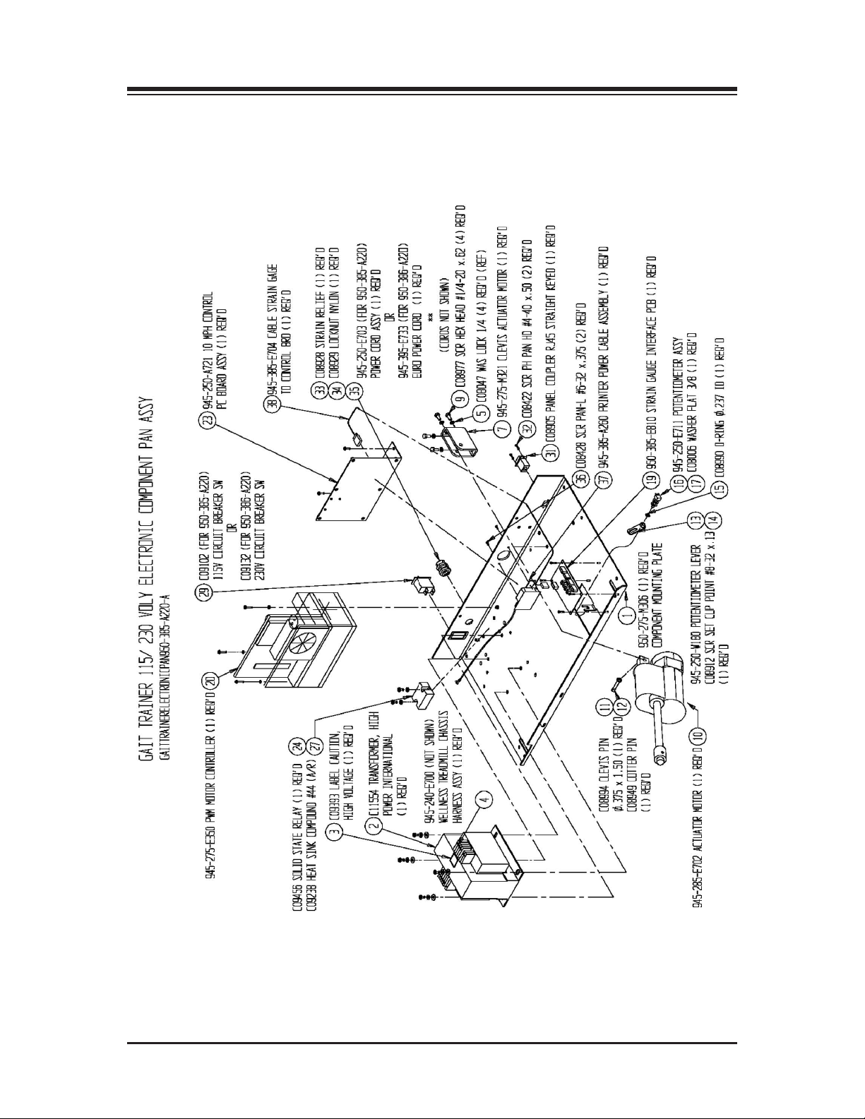
CONTENTS
— 17-5 — ASSEMBLY DRAWINGS AND SCHEMATICS
Page 54
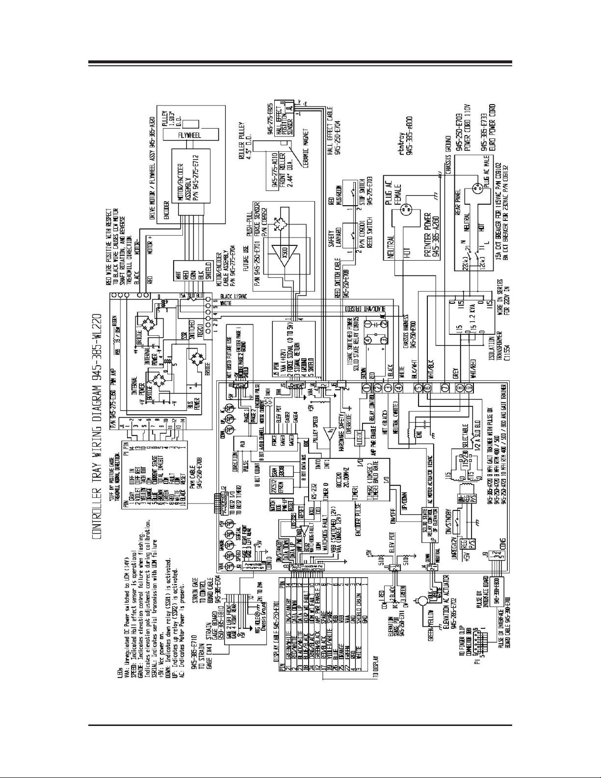
CONTENTS
ASSEMBLY DRAWINGS AND SCHEMATICS — 17-6 —
Page 55

BIODEX
20 Ramsay Road, Shirley, New York, 11967-4704, Tel: 800-224-6339 (In NY and Int’l, call 631-924-9000), Fax: 631-924-9338, Email: [email protected], www.biodex.com
Biodex Medical Systems, Inc.
 Loading...